EP4449907A1 - Flavour inhaler, and smoking system - Google Patents
Flavour inhaler, and smoking system Download PDFInfo
- Publication number
- EP4449907A1 EP4449907A1 EP21968102.0A EP21968102A EP4449907A1 EP 4449907 A1 EP4449907 A1 EP 4449907A1 EP 21968102 A EP21968102 A EP 21968102A EP 4449907 A1 EP4449907 A1 EP 4449907A1
- Authority
- EP
- European Patent Office
- Prior art keywords
- protrusions
- consumable product
- accommodating part
- longitudinal direction
- opening
- Prior art date
- Legal status (The legal status is an assumption and is not a legal conclusion. Google has not performed a legal analysis and makes no representation as to the accuracy of the status listed.)
- Pending
Links
Images






Classifications
-
- A—HUMAN NECESSITIES
- A24—TOBACCO; CIGARS; CIGARETTES; SIMULATED SMOKING DEVICES; SMOKERS' REQUISITES
- A24F—SMOKERS' REQUISITES; MATCH BOXES; SIMULATED SMOKING DEVICES
- A24F40/00—Electrically operated smoking devices; Component parts thereof; Manufacture thereof; Maintenance or testing thereof; Charging means specially adapted therefor
- A24F40/40—Constructional details, e.g. connection of cartridges and battery parts
-
- A—HUMAN NECESSITIES
- A24—TOBACCO; CIGARS; CIGARETTES; SIMULATED SMOKING DEVICES; SMOKERS' REQUISITES
- A24F—SMOKERS' REQUISITES; MATCH BOXES; SIMULATED SMOKING DEVICES
- A24F40/00—Electrically operated smoking devices; Component parts thereof; Manufacture thereof; Maintenance or testing thereof; Charging means specially adapted therefor
- A24F40/40—Constructional details, e.g. connection of cartridges and battery parts
- A24F40/42—Cartridges or containers for inhalable precursors
-
- A—HUMAN NECESSITIES
- A24—TOBACCO; CIGARS; CIGARETTES; SIMULATED SMOKING DEVICES; SMOKERS' REQUISITES
- A24F—SMOKERS' REQUISITES; MATCH BOXES; SIMULATED SMOKING DEVICES
- A24F40/00—Electrically operated smoking devices; Component parts thereof; Manufacture thereof; Maintenance or testing thereof; Charging means specially adapted therefor
- A24F40/40—Constructional details, e.g. connection of cartridges and battery parts
- A24F40/46—Shape or structure of electric heating means
-
- A—HUMAN NECESSITIES
- A24—TOBACCO; CIGARS; CIGARETTES; SIMULATED SMOKING DEVICES; SMOKERS' REQUISITES
- A24D—CIGARS; CIGARETTES; TOBACCO SMOKE FILTERS; MOUTHPIECES OF CIGARS OR CIGARETTES; MANUFACTURE OF TOBACCO SMOKE FILTERS OR MOUTHPIECES
- A24D1/00—Cigars; Cigarettes
- A24D1/20—Cigarettes specially adapted for simulated smoking devices
-
- A—HUMAN NECESSITIES
- A24—TOBACCO; CIGARS; CIGARETTES; SIMULATED SMOKING DEVICES; SMOKERS' REQUISITES
- A24F—SMOKERS' REQUISITES; MATCH BOXES; SIMULATED SMOKING DEVICES
- A24F40/00—Electrically operated smoking devices; Component parts thereof; Manufacture thereof; Maintenance or testing thereof; Charging means specially adapted therefor
- A24F40/20—Devices using solid inhalable precursors
Definitions
- the present disclosure relates to a flavour inhaler and a smoking system.
- a guide has been provided in an accommodating part of a known flavour inhaler so as to appropriately accommodate a consumable product including a smokable product in the accommodating part.
- Document 1 discloses techniques in which an opening part, through which a consumable product is inserted, is provided, and a plurality of raised parts are provided in a collar provided inside a housing of a flavour inhaler so as to hold the consumable product accommodated in the housing.
- flavour inhaler when the consumable product is inserted into the accommodating part, it is desired that the consumable product be smoothly inserted with low resistance. Meanwhile, after smoking has started, it is desired that the consumable product be sufficiently supported in the accommodating part so as not to allow dropping of the consumable product from the flavour inhaler during the smoking.
- flavour inhaler and a smoking system that facilitate insertion of a consumable product into an accommodating part and that can appropriately hold the consumable product in the accommodating part are provided.
- a first embodiment of the present disclosure is a flavour inhaler that includes an accommodating part configured to accommodate consumable product including a smokable product.
- the accommodating part has an opening configured to allow insertion of the consumable product therein, a first space formation part that is connected to the opening and forms a space throughout a periphery between the first space formation part and an outer peripheral surface of the accommodated consumable product, a second space formation part that is positioned at a farther side from the opening than the first space formation part and forms a space throughout the periphery between the second space formation part and the outer peripheral surface of the accommodated consumable product, a first support part that is positioned between the first space formation part and the second space formation part in a longitudinal direction of the accommodating part and presses the outer peripheral surface of the consumable product to support the consumable product, and a second support part that is positioned at a farther side from the opening than the second space formation part in the longitudinal direction of the accommodating part and presses the outer peripheral surface of the consumable product to support the consumable product.
- the first space formation part connected to the opening, the first support part, the second space formation part, and the second support part are disposed in this order from the opening through which the consumable product is inserted.
- the consumable product having passed through the opening is easily inserted due to the first space formation part, and the consumable product can be appropriately supported by the first support part and the second support part.
- the consumable product pressed by the first support part and the second support part bulges at a portion corresponding to the second space formation part positioned between the first support part and the second support part and is engaged with the second space formation part.
- dropping of the consumable product can be suppressed.
- a second embodiment of the present disclosure is the flavour inhaler according to the above-described first embodiment in which the accommodating part has a chamber having a heating region configured to heat the consumable product and a guide part configured to guide, to the chamber, the consumable product having been inserted from the opening.
- the second space formation part and the second support part are provided at the chamber.
- the first space formation part and the first support part are provided at the guide part.
- the second space formation part and the second support part are provided in the chamber configured to heat the consumable product
- the first space formation part and the first support part are provided in the guide part configured to guide the consumable product having been inserted from the opening to the chamber.
- the consumable product can be appropriately supported on one side and the other side of a border of the heating region by using the first support part disposed in a non-heating region and the second support part disposed in the heating region.
- a third embodiment of the present disclosure is the flavour inhaler according to the above-described first and second embodiments in which the second support part has a set of contact parts that are configured to be in contact with the outer peripheral surface of the accommodated consumable product and disposed so as to be substantially equally spaced apart from each other in a peripheral direction of the accommodating part, and a set of connecting parts connecting the set of contact parts to each other.
- the contact parts to be in contact with the outer peripheral surface of the accommodated consumable product and the connecting parts not to be in contact with the outer peripheral surface of the consumable product are provided.
- clearances are formed between the consumable product and the connecting parts, and air having flowed from the opening passes through these clearances and flows into the flavour inhaler. Accordingly, airflow paths appropriate for smoking can be formed.
- a fourth embodiment of the present disclosure is the flavour inhaler according to the above-described third embodiment in which the first support part has a set of first protrusions that protrude from an inner wall surface of the first support part and are disposed so as to be substantially equally spaced apart from each other in the peripheral direction of the accommodating part.
- Each of the set of first protrusions is provided at a position that overlaps with a corresponding one of the set of contact parts when seen in the longitudinal direction of the accommodating part.
- the first protrusions protrude from the inner wall surface of the first support part at the positions, when seen in the longitudinal direction of the accommodating part, overlapped with the contact parts to be in contact with the outer peripheral surface of the consumable product.
- the consumable product can be supported at two portions in the longitudinal direction of the accommodating part at the same positions in the peripheral direction of the accommodating part.
- the consumable product deformed by the first protrusions is retained in the accommodating part. Thus, dropping of the consumable product is suppressed.
- a fifth embodiment of the present disclosure is the flavour inhaler according to the above-described fourth embodiment in which, when the consumable product is inserted into the opening and accommodated in the accommodating part in a direction substantially parallel to the longitudinal direction of the accommodating part, in a section perpendicular to the longitudinal direction of the accommodating part, each of the set of first protrusions protrudes to an inside of a virtual external shape indicating the outer peripheral surface of the consumable product that has not been deformed.
- each of the set of first protrusions protrudes to the inside of a virtual external shape indicating the outer peripheral surface of the undeformed consumable product.
- the consumable product can be grasped by the set of first protrusions.
- a sixth embodiment of the present disclosure is the flavour inhaler according to the above-described fourth and fifth embodiments in which the set of first protrusions extend in the longitudinal direction of the accommodating part.
- the set of first protrusions have inclined parts such that, when a section in the longitudinal direction of the accommodating part is seen, a distance between the inclined parts and a center in a radial direction of the accommodating part reduces as a distance between the inclined parts and the opening increases.
- the first protrusions of the first support part that support the consumable product inserted through the opening first have the inclined parts.
- the distance between the inclined parts and the center in the radial direction of the accommodating part reduces as the distance between the inclined parts and the opening increases.
- a seventh embodiment of the present disclosure is the flavour inhaler according to the above-described fourth to sixth embodiments in which, when a section perpendicular to the longitudinal direction of the accommodating part is seen, each of the set of first protrusions has a first side, a second side, and a vertex connecting the first side and the second side to each other. An angle formed between the first side and the second side is an obtuse angle.
- the first protrusions of the first support part protrude from the inner wall surface of the first support part to form an obtuse triangular shape.
- the first protrusions have no sharp vertices. Accordingly, damage to the consumable product can be suppressed.
- contact surfaces where the first protrusions and the consumable product are to be in contact with each other can be increased, and accordingly, dropping of the consumable product can be more effectively suppressed.
- An eighth embodiment of the present disclosure is the flavour inhaler according to the above-described seventh embodiment in which the set of first protrusions include a pair of first protrusions facing each other in the peripheral direction of the accommodating part.
- the pair of first protrusions facing each other each have a first surface that has the first side and extends in the longitudinal direction of the accommodating part, a second surface that has the second side and extends in the longitudinal direction, and a ridge that connects the first surface and the second surface to each other, has the vertex, and extends in the longitudinal direction. None of two ridges of the pair of protrusions facing each other is in parallel with the longitudinal direction.
- the two ridges are inclined in directions opposite to each other with reference to a straight line connecting end parts of the two ridges positioned at an opposite side from the opening in the longitudinal direction or a straight line connecting end parts of the two ridges positioned at an opening side in the longitudinal direction.
- two ridges each of which connects the first surface and the second surface to each other, includes the vertex, and extends in the longitudinal direction in a corresponding one of the pair of the first protrusions, are inclined in the directions opposite to each other with reference to the straight line connecting the end parts positioned at the opposite side from the opening in the longitudinal direction of the accommodating part or the straight line connecting the end parts on the opening side in the longitudinal direction.
- clockwise or counterclockwise uniform torque is produced around the insertion direction of the consumable product.
- the consumable product can be smoothly inserted during the insertion, and dropping of the consumable product can be reliably suppressed after the insertion.
- a ninth embodiment of the present disclosure is the flavour inhaler according to the above-described fourth to eighth embodiments in which the first support part has a set of second protrusions that protrude from the inner wall surface of the first support part and are provided so as to be substantially equally spaced apart from each other in the peripheral direction of the accommodating part.
- the set of second protrusions are provided at positions that overlap with the set of connecting parts when seen in the longitudinal direction of the accommodating part.
- the set of second protrusions are additionally provided at the positions, when seen in the longitudinal direction of the accommodating part, overlapped with the connecting parts that are not to be in contact with the consumable product.
- the consumable product can be reliably supported at the first support part and the second support part. Specifically, the consumable product pressed by the contact parts in the second support part bulges toward the connecting parts, and the bulged parts are retained at the second protrusions. Thus, dropping of the consumable product can be suppressed.
- the consumable product pressed by the first protrusions and deformed is retained at the second protrusions. Thus, dropping of the consumable product can be suppressed.
- a tenth embodiment of the present disclosure is the flavour inhaler according to the above-described ninth embodiment in which, when the consumable product is inserted into the opening and accommodated in the accommodating part in the direction substantially parallel to the longitudinal direction of the accommodating part, in a section perpendicular to the longitudinal direction of the accommodating part, the set of second protrusions are positioned outside a virtual external shape indicating the outer peripheral surface of the consumable product that has not been deformed.
- each of the set of first protrusions protrudes to the inside of the virtual external shape indicating the outer peripheral surface of the undeformed consumable product while each of the set of second protrusions is positioned outside the virtual external shape.
- the consumable product is grasped by the first protrusions while the consumable product is not firmly grasped by the second protrusions.
- the second protrusions can support the consumable product.
- An eleventh embodiment of the present disclosure is the flavour inhaler according to the above-described tenth embodiment in which each of the set of second protrusions has a curved part curved along the virtual external shape.
- each of the second protrusions provided in the first support part has the curved part curved along the virtual external shape indicating the outer peripheral surface of the accommodated consumable product.
- the consumable product can be appropriately supported when the consumable product wobbles.
- a twelfth embodiment of the present disclosure is the flavour inhaler according to the above-described ninth to eleventh embodiments in which third end parts of the set of second protrusions positioned at the opposite side from the opening in the longitudinal direction of the accommodating part are connected to the second space formation part.
- the third end parts of the second protrusions positioned at the opposite side from the opening are positioned at a border between the first support part and the second space formation part.
- the consumable product bulged in the second space formation part is retained at the second protrusions having the third end parts facing the second space formation part.
- dropping of the consumable product can be further suppressed.
- a thirteenth embodiment of the present disclosure is the flavour inhaler according to the above-described ninth to twelfth embodiments in which a shape of the set of first protrusions and a shape of the set of second protrusions are different from each other.
- the shape of the first protrusions and the shape of the second protrusions provided in the first support part are different from each other.
- the first protrusions and the second protrusions having different functions can have different shapes appropriate for the different functions.
- a fourteenth embodiment of the present disclosure is the flavour inhaler according to the above-described ninth to thirteenth embodiments in which the set of first protrusions and the set of second protrusions are disposed such that the set of first protrusions and the set of second protrusions overlap at least partially with each other in the longitudinal direction of the accommodating part.
- the first protrusions and the second protrusions provided in the first support part are disposed so as to be overlapped with each other in the longitudinal direction of the accommodating part.
- the length of the first support part in the longitudinal direction can be reduced. This can contribute to size reduction of the accommodating part of the flavour inhaler.
- a fifteenth embodiment of the present disclosure is the flavour inhaler according to the above-described thirteenth and fourteenth embodiments in which the set of first protrusions and the set of second protrusions extend in the longitudinal direction of the accommodating part.
- Each of the set of first protrusions has a first inclined surface that, when a section in the longitudinal direction is seen, extends from a first end part of the first protrusion positioned at the opposite side from the opening in the longitudinal direction and that is inclined such that a distance between the first inclined surface and the center of the accommodating part in the radial direction reduces as a distance between the first inclined surface and the opening reduces.
- Each of the set of second protrusions has a second inclined surface that, when a section in the longitudinal direction is seen, extends from a second end part of the second protrusion positioned at the opening side in the longitudinal direction and that is inclined such that a distance between the second inclined surface and the center of the accommodating part in the radial direction reduces as a distance between the second inclined surface and the opening increases.
- the first inclined surface of each of the set of first protrusions and the second inclined surface of each of the set of second protrusions are disposed such that the first inclined surface and the second incline surface overlap at least partially with each other in the longitudinal direction of the accommodating part.
- An inclination angle or a radius of curvature of the first inclined surface is substantially equal to an inclination angle or a radius of curvature of the second inclined surface.
- the first inclined surfaces extending from the first end parts on the opposite side from the opening are provided in the first protrusions
- the second inclined surfaces extending from the second end parts on the opening side are provided in the second protrusions
- the first inclined surfaces and the second inclined surfaces are disposed so as to overlap with each other in the longitudinal direction of the accommodating part
- the first inclined surfaces and the second inclined surfaces have substantially the same inclination angle or radius of curvature.
- the consumable product when the consumable product is inserted from the opening, the consumable product is grasped by the set of first protrusions first, and then, part of the deformed consumable product is retained at the pair of second protrusions. At this time, the degree of strength of grasping by the first protrusions is reduced while the degree of strength of grasping by the second protrusions is increased. This enables gradual grasping. Thus, resistance in insertion of the consumable product can be reduced, and dropping of the consumable product can be suppressed.
- a sixteenth embodiment of the present disclosure is the flavour inhaler according to the above-described third embodiment in which the set of contact parts include a pair of contact parts facing each other in the peripheral direction of the accommodating part and the set of connecting parts include a pair of connecting parts facing each other in the peripheral direction of the accommodating part.
- the first support part has a plurality of first protrusions that protrude from an inner wall surface of the first support part.
- the plurality of first protrusions are disposed such that none of the plurality of first protrusions intersects the first virtual line or the second virtual line.
- none of the plurality of first protrusions protruding from the inner wall surface of the first support part intersects the first virtual line or the second virtual line.
- the first virtual line connects the centers of the pair of contact parts provided in the second support part of the accommodating part and to be in contact with the outer peripheral surface of the accommodated consumable product.
- the second virtual line connects the centers of the pair of connecting parts not to be in contact with the outer peripheral surface of the consumable product.
- the first protrusions further press portions of the consumable product that overlap with the contact parts in the peripheral direction of the accommodating part; and the first protrusions block the airflow paths formed between the consumable product and the connecting parts.
- a seventeenth embodiment of the present disclosure is the flavour inhaler according to the above-described third to sixteenth embodiments in which the chamber includes a heat source configured to supply heat to the heating region.
- the heat source is disposed such that the heat source and the second support part overlap with each other in the longitudinal direction of the accommodating part.
- the heat source configured to supply heat to the heating region of the chamber to heat the consumable product is disposed such that the heat source and the second support part overlap with each other.
- the second support part has the pair of contact parts in contact with the outer peripheral surface of the accommodated consumable product.
- An eighteenth embodiment of the present disclosure is the flavour inhaler according to the above-described seventeenth embodiment in which the heat source is a film heater.
- the film heater is wound around an outer periphery of the chamber.
- the heat source configured to supply heat to the heating region of the chamber to heat the consumable product is the film heater wound around the outer periphery of the chamber.
- the consumable product can be heated with a simple configuration.
- a nineteenth embodiment of the present disclosure is the flavour inhaler according to the above-described second to eighteenth embodiments in which an expression 1 below is satisfied: L 2 ⁇ L 1 / 2
- the first space formation part in the guide part in which the first space formation part connected to the opening and the first support part supporting the consumable product are provided, the first space formation part has the length equal to or greater than 1/2 of the entire length of the guide part in the longitudinal direction.
- the first space formation part having a sufficient length is formed at a position connected to the opening of the accommodating part, the consumable product can be smoothly inserted.
- a twentieth embodiment of the present disclosure is a smoking system that includes the flavour inhaler according to the above-described first to nineteenth embodiments and the consumable product.
- the smoking system that facilitates insertion of the consumable product into the accommodating part of the flavour inhaler and that can appropriately hold the consumable product in the accommodating part can be provided.
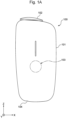
- Fig. 1A is a schematic front view of a flavour inhaler 100 according to the first embodiment of the present disclosure.
- Fig. 1B is a schematic top view of the flavour inhaler 100.
- Fig. 1C is a schematic bottom view of the flavour inhaler 100.
- the X-Y-Z orthogonal coordinate system may be indicated for convenience of description. In this coordinate system, the Z axis is directed upward in the vertical direction, the X-Y plane is placed so as to cut the flavour inhaler 100 in the horizontal direction, and the Y axis is placed so as to extend from a front surface to a rear surface of the flavour inhaler 100.
- the Z axis can be referred to as an insertion direction of a consumable product to be accommodated in a chamber 50 of an atomizing part 30, which will be described later, or an axial direction of the chamber 50.
- the X axis is perpendicular to the Y axis and the Z axis.
- the flavour inhaler 100 generates an aerosol containing a flavour by, for example, heating a stick-shaped consumable product having a flavour source containing an aerosol source.
- the flavour inhaler 100 includes an outer housing 101, a slide cover 102, a switch part 103, and terminals 104.
- the outer housing 101 serves as an outermost housing of the flavour inhaler 100 and has such a size that the flavour inhaler 100 can be held within the hand of a user. When the user uses the flavour inhaler 100, the user can hold the flavour inhaler 100 with the hand and inhale the aerosol.
- the outer housing 101 may be formed by assembling a plurality of members.
- the outer housing 101 may be formed of, for example, metal such as aluminum.
- the material of the outer housing 101 may include a member formed of resin, for example, polycarbonate (PC), acrylonitrile-butadiene-styrene (ABS) resin, polyetherether ketone (PEEK), a polymer alloy containing a plurality of types of polymers, or the like.
- resin for example, polycarbonate (PC), acrylonitrile-butadiene-styrene (ABS) resin, polyetherether ketone (PEEK), a polymer alloy containing a plurality of types of polymers, or the like.
- the outer housing 101 has an opening 101a for receiving the consumable product, and the slide cover 102 is slidably attached to the outer housing 101 so as to close the opening 101a.
- the slide cover 102 is movable along an outer front surface of the outer housing 101 between a closing position (the position indicated in Figs. 1A and 1B ) where the opening 101a of the outer housing 101 is closed by the slide cover 102 and an open position where the opening 101a is open.
- a closing position the position indicated in Figs. 1A and 1B
- the opening 101a of the outer housing 101 is closed by the slide cover 102
- an open position where the opening 101a is open.
- the opening 101a of the outer housing 101 is open outward corresponding to a first opening 70a of an insertion guide member 70 and a second opening 52 of the chamber 50.
- the switch part 103 is used to switch on or off operation of the flavour inhaler 100.
- the switch part 103 may be a switch provided outside the outer housing 101 or a switch positioned inside the outer housing 101.
- the switch is indirectly pressed down when the switch part 103 in a front surface of the outer housing 101 is pressed down.
- the switch of the switch part 103 is positioned inside the outer housing 101 is described.
- the terminals 104 are an interface such as a universal serial bus (USB) to connect the flavour inhaler 100 to, for example, an external power supply.
- USB universal serial bus
- the power supply included in the flavour inhaler 100 is a rechargeable battery
- the external power supply causes an electric current to flow to the power supply to allow recharging of the power supply.
- the flavour inhaler 100 can be configured so that the flavour inhaler 100 can transmit data related to the operation of the flavour inhaler 100 to an external device when a data transmission cable is connected to the terminals 104.
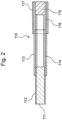
- Fig. 2 is a schematic side sectional view of a consumable product 110.
- a smoking system can be configured with the flavour inhaler 100 and the consumable product 110.
- the consumable product 110 includes a smokable product 111, a tubular member 114, a hollow filter part 116, and a filter part 115.
- the smokable product 111 is wrapped with first wrapping paper 112.
- the tubular member 114, the hollow filter part 116, and the filter part 115 are wrapped with second wrapping paper 113 different from the first wrapping paper 112.
- the second wrapping paper 113 is also wrapped around part of the first wrapping paper 112 wrapped around the smokable product 111.
- the tubular member 114, the hollow filter part 116, the filter part 115 are connected to the smokable product 111.
- the second wrapping paper 113 may be omitted. In this case, the tubular member 114, the hollow filter part 116, and the filter part 115 are connected to the smokable product 111 by using the first wrapping paper 112.
- a lip release agent 117 for facilitating release of the lip of the user from the second wrapping paper 113 is applied near an end part on the filter part 115 side.
- the part of the consumable product 110 to which the lip release agent 117 is applied functions as an inhalation port of the consumable product 110.
- a perforation may be provided in the hollow filter part 116 so as to be concentric with a peripheral direction of the hollow filter part 116. The perforation facilitates flowing of the air from the outside due to inhalation by the user, and the air flowing through the perforation can reduce the temperature of a component and the air flowing from the consumable product 110.
- the smokable product 111 can include, for example, a flavour source such as tobacco and an aerosol source. Furthermore, the first wrapping paper 112 wrapped around the smokable product 111 can be a sheet member having a permeability.
- the tubular member 114 can be a paper tube or a hollow filter.
- the consumable product 110 includes the smokable product 111, the tubular member 114, the hollow filter part 116, and the filter part 115 in the example illustrated in Fig. 2 , the configuration of the consumable product 110 is not limited to this.
- the hollow filter part 116 may be omitted to allow the tubular member 114 and the filter part 115 to be arranged adjacent to each other.
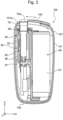
- Fig. 3 is a sectional view of the flavour inhaler 100 seen in an arrow 3-3 direction illustrated in Fig. 1B .
- a placement part 10 is provided inside the outer housing 101 of the flavour inhaler 100.
- the placement part 10 can be formed of, for example, resin, in particular, formed of PC, ABS resin, PEEK, a polymer alloy containing a plurality of types of polymers, or the like.
- the placement part 10 may include a part formed of metal such as, for example, aluminum.
- the placement part 10 is preferably formed of PC.
- the power supply part 20 and the atomizing part 30 are provided in the internal space of the placement part 10.
- the power supply part 20 or the atomizing part 30 is not replaceable after the flavour inhaler 100 has been assembled.
- the outer housing 101 and the placement part 10 may be collectively referred to as a housing.
- the power supply part 20 includes the power supply 21.
- the power supply 21 can be, for example, a rechargeable battery or a non-rechargeable battery.
- the power supply 21 is electrically connected to the atomizing part 30.
- the power supply 21 can supply electric power to the atomizing part 30 so as to appropriately heat the consumable product 110.
- the atomizing part 30 includes the chamber 50 extending in the insertion direction of the consumable product 110 (Z axis direction), the heating part 40 covering part of the chamber 50, a thermal insulation part 32, and the insertion guide member 70 having a substantially tubular shape.
- the chamber 50 accommodates the consumable product 110.
- the heating part 40 is in contact with an outer peripheral surface of the chamber 50 and heats the consumable product 110 accommodated in the chamber 50.
- a bottom member 36 may be provided at a bottom part of the chamber 50. The bottom member 36 can function as a stopper with which the consumable product 110 inserted into the chamber 50 is positioned.
- the bottom member 36 has projections and depressions in a surface to be in contact with the consumable product 110, and a space through which air can be supplied to the surface to be in contact with the consumable product 110 can be defined.
- the bottom member 36 can be formed of, for example, resin, in particular, formed of PC, ABS resin, PEEK, a polymer alloy containing a plurality of types of polymers, or the like, or formed of metal such as aluminum.
- the bottom member 36 is preferably formed of a raw material having a low thermal conductivity.
- a combination of the insertion guide member 70 and the chamber 50 is an example of an accommodating part of the present disclosure.
- the insertion guide member 70 is an example of a guide part of the present disclosure.
- the heating part 40 is an example of a heat source of the present disclosure.
- the thermal insulation part 32 generally has a substantially tubular shape and is disposed so as to cover the chamber 50.
- the thermal insulation part 32 can include, for example, an aerogel sheet.
- the insertion guide member 70 is provided between the outer housing 101 and the chamber 50. When the insertion guide member 70 is inserted into the housing from the opening 101a of the outer housing 101, a nail is brought into engagement with the housing, and the insertion guide member 70 is unable to be moved to the outside of the housing.
- the insertion guide member 70 can be formed of, for example, resin, in particular, formed of PC, ABS resin, PEEK, polyetherimide (PEI) a polymer alloy containing a plurality of types of polymers, or the like.
- the insertion guide member 70 may be formed of metal, glass, ceramic, or the like. From the viewpoint of thermal resistance, the insertion guide member 70 is preferably formed of PEEK.
- the insertion guide member 70 communicates with the outside of the flavour inhaler 100.
- the insertion guide member 70 guides insertion of the consumable product 110 into the chamber 50.
- the slide cover 102 exists at the open position, the slide cover 102 allows the first opening 70a of the insertion guide member 70 to be exposed to the outside and covers at least part of the insertion guide member 70 in the axial direction of the chamber 50.
- the first opening 70a is provided so as to correspond to the second opening 52 of the chamber 50, which will be described later.
- a two-dot chain line indicates a state of the slide cover 102 that is closed so as to cover the entirety of the first opening 70a of the insertion guide member 70.
- the first opening 70a is an example of an opening of the accommodating part of the present disclosure.
- the flavour inhaler 100 further includes a first holding part 37 and a second holding part 38 that support both ends of the chamber 50 and both ends of the thermal insulation part 32.
- the first holding part 37 is disposed so as to hold an end part of the chamber 50 and an end part of the thermal insulation part 32 on the negative side in the Z axis direction.
- the second holding part 38 is disposed so as to hold an end part of the chamber 50 and an end part of the thermal insulation part 32 on the slide cover 102 side (the positive side in the Z axis direction).
- Fig. 4A is a perspective view of the chamber 50.
- Fig. 4B is a sectional view of the chamber 50 seen in an arrow 4B-4B direction illustrated in Fig. 4A .
- Fig. 5A is a sectional view of the chamber 50 seen in an arrow 5A-5A direction illustrated in Fig. 4B .
- Fig. 5B is a sectional view of the chamber 50 seen in an arrow 5B-5B direction illustrated in Fig. 4B .
- Fig. 6 is a perspective view illustrating the chamber 50 and the heating part 40.
- the chamber 50 can have a tubular shape including the second opening 52 into which the consumable product 110 is to be inserted and a tubular side wall part 60 that is to accommodate the consumable product 110.
- a flange part 52A is formed at the end part of the chamber 50 that defines the second opening 52.
- the flange part 52A of the chamber 50 is connected to an end part of the insertion guide member 70 on the negative side in the Z axis direction.
- the chamber 50 is preferably formed of a material having thermal resistance and a small thermal expansion coefficient.
- the chamber 50 can be formed of stainless steel or the like.
- the chamber 50 may be formed of resin such as PEEK, glass, ceramic, or the like. This allows effective heating of the consumable product 110 from the chamber 50.
- the shape of the chamber 50 is not limited to the tubular shape, and the chamber 50 may have a cup shape.
- the side wall part 60 is an example of a second support part of the present disclosure.
- the side wall part 60 includes contact parts 62 and separated parts 66.
- the contact parts 62 are in contact with or press parts of the consumable product 110 in the axial direction of the chamber 50, and the separated parts 66 are kept separated from the consumable product 110. That is, the chamber 50 compresses the inserted consumable product 110 to hold the consumable product 110.
- the “desired position in the chamber 50” refers to a position where the consumable product 110 is appropriately heated or a position of the consumable product 110 to be smoked by the user.
- the contact parts 62 have respective inner surfaces 62a and respective outer surfaces 62b.
- the separated parts 66 have respective inner surfaces 66a and respective outer surfaces 66b.
- the heating part 40 is disposed on the outer surfaces 62b of the contact parts 62.
- the heating part 40 is preferably disposed on the outer surfaces 62b of the contact parts 62 without a gap between the heating part 40 and the outer surfaces 62b.
- the heating part 40 may include an adhesive layer.
- the heating part 40 including the adhesive layer is preferably disposed on the outer surfaces 62b of the contact parts 62 without a gap between the heating part 40 and the outer surfaces 62b.
- the contact parts 62 are an example of a set of contact parts of the present disclosure.
- the separated parts 66 are an example of a set of connecting parts of the present disclosure.
- the shape of the side wall part 60 of the chamber 50 is not limited to the shape including a pair of contact parts 62 and a pair of separated parts 66.
- An appropriate number of contact parts can be provided as long as the contact parts are disposed so as to be substantially equally spaced apart from each other in the peripheral direction of the chamber 50. Separated parts can be provided so as to connect these contact parts to each other.
- the outer surfaces 62b of the contact parts 62 are flat surfaces.
- the outer surfaces 62b of the contact parts 62 are flat surfaces, in the case where a strip-shaped electrode 48 is connected to the heating part 40 disposed on the outer surfaces 62b of the contact parts 62 as illustrated Fig. 6 , bending of the strip-shaped electrode 48 can be suppressed.
- the inner surfaces 62a of the contact parts 62 are flat surfaces.
- the thickness of the contact parts 62 is uniform.
- the chamber 50 has two contact parts 62 in the peripheral direction of the chamber 50, and two contact parts 62 face each other so as to be parallel to each other.
- the distance between the inner surfaces 62a of two contact parts 62 is at least partially smaller than the width of a portion of the consumable product 110 to be inserted into the chamber 50, the portion being disposed between the contact parts 62.
- the inner surfaces 66a of the separated parts 66 can have a generally arc-shaped section in a plane perpendicular to the longitudinal direction of the chamber 50 (Z axis direction). Furthermore, the separated parts 66 are disposed so as to be adjacent to the contact parts 62 in the peripheral direction. That is, the contact parts 62 and the separated parts 66 form a noncircular inner peripheral surface in a section perpendicular to the longitudinal direction of the chamber 50 (Z axis direction).
- the chamber 50 can have a hole 56a in a bottom part 56 of the chamber 50 so that the bottom member 36 illustrated in Fig. 3 extends through the bottom member 36 and is disposed inside the chamber 50.
- the bottom member 36 can be fixed inside the bottom part 56 of the chamber 50 with an adhesive or the like.
- the adhesive interposed between the bottom member 36 and the bottom part 56 can include a resin material such as epoxy resin.
- an inorganic adhesive such as cement or a weld can be used.
- the bottom member 36 provided in the bottom part 56 can support part of the consumable product 110 inserted into the chamber 50 so that at least part of an end surface of the consumable product 110 is exposed.
- the bottom part 56 can support part of the consumable product 110 so that the exposed end surface of the consumable product 110 communicates with clearances 67 (see Fig. 7 ), which will be described later.
- the chamber 50 preferably has a tubular non-holding part 54 between the second opening 52 and the side wall part 60.
- a gap can be formed between the non-holding part 54 and the consumable product 110.
- the width of the gap formed between the non-holding part 54 and the consumable product 110 may be substantially uniform throughout a periphery in the peripheral direction of the chamber 50 or varied in the peripheral direction of the chamber 50. For example, when seen in the longitudinal direction, the width of the gap at positions overlapping with the contact parts 62 may be greater than the width of the gap at positions overlapping with the separated parts 66.
- the width of the gap at the positions overlapping with the contact parts 62 may be smaller than the width of the gap at the positions overlapping with the separated parts 66.
- the chamber 50 preferably has first guide parts 58 that have tapered surfaces 58a connecting an inner surface of the non-holding part 54 and the inner surfaces 62a of the contact parts 62 to each other.
- the non-holding part 54 is an example of a second space formation part of the present disclosure.
- the heating part 40 includes a heating element 42.
- the heating element 42 may be, for example, a heating track or a film heater.
- the heating element 42 is disposed such that the heating element heats the contact parts 62 of the chamber 50 and is not in contact with the separated parts 66 of the chamber 50.
- the heating element 42 is preferably disposed only on the outer surfaces of the contact parts 62.
- Part of the heating element 42 to heat the separated parts 66 of the chamber 50 and part of the heating element 42 to heat the contact parts 62 may have different heating abilities.
- the heating element 42 may heat the contact parts 62 to a higher temperature than the temperature to which the heating element 42 heats the separated parts 66.
- the heating part 40 preferably includes an electrical insulation member 44 that covers at least one of surfaces of the heating element 42.
- the electrical insulation member 44 is disposed so as to cover both the surfaces of the heating element 42.
- Fig. 7 is a sectional view illustrated in Fig. 5B when the consumable product 110 is disposed at the desired position in the chamber 50.
- the consumable product 110 can be brought into contact with and pressed by the contact parts 62 of the chamber 50.
- the clearances 67 are formed between the consumable product 110 and the separated parts 66.
- the clearances 67 can communicate with the second opening 52 of the chamber 50 and the end surface of the consumable product 110 positioned in the chamber 50.
- airflow paths are formed between the consumable product 110 and the separated parts 66.
- Fig. 8 is an exploded perspective view illustrating an internal structure of the accommodating part including the insertion guide member 70 and the chamber 50.
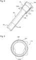
- Fig. 9 is a sectional view of the insertion guide member 70 taken along a section perpendicular to the axial direction of the chamber 50 illustrating arrangement of a pair of first protrusions 214A in the peripheral direction.
- the section perpendicular to the axial direction of the chamber 50 is the X-Y plane, and the axial direction of the chamber 50 is the insertion direction of the consumable product 110 and the Z axis direction.
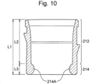
- FIG. 10 is a sectional view of the insertion guide member 70 taken along the axial direction of the chamber 50 illustrating arrangement of the pair of first protrusions 214A in the longitudinal direction.
- Fig. 11 is a sectional view taken along the axial direction of the chamber 50 illustrating main portions the insertion guide member 70 and the chamber 50 in which the consumable product 110 is accommodated.
- the axial direction of the insertion guide member 70 and the axial direction of the chamber 50 are examples of the longitudinal direction of the accommodating part of the present disclosure.
- the pair of first protrusions 214A are provided on an inner wall surface of the insertion guide member 70.
- the pair of first protrusions 214A protrude toward the center in a radial direction of the insertion guide member 70 and face each other in a peripheral direction of the insertion guide member 70.
- a part in the axial direction of the insertion guide member 70 where the first protrusions 214A are provided is referred to as a non-protruding part 212 and a part in the axial direction of the insertion guide member 70 where the first protrusions 214A are provided is referred to as a protruding part 214.
- the width of a gap formed between the non-protruding part 212 of the insertion guide member 70 and the consumable product 110 may be substantially uniform throughout the periphery in the peripheral direction of the insertion guide member 70 or varied in the peripheral direction of the insertion guide member 70.
- the width of the gap at positions overlapping with the contact parts 62 may be greater than the width of the gap at positions overlapping with the separated parts 66.
- the width of the gap at the positions overlapping with the contact parts 62 may be smaller than the width of the gap at the positions overlapping with the separated parts 66.
- the non-protruding part 212 of the insertion guide member 70 is an example of a first space formation part of the present disclosure.
- the protruding part 214 of the insertion guide member 70 is an example of a first support part of the present disclosure.
- the first protrusions 214A provided on the inner wall surface of the insertion guide member 70 are not limited to two first protrusions 214A facing each other in the peripheral direction of the insertion guide member 70. As long as the first protrusions 214A are disposed so as to be substantially equally spaced apart from each other in the peripheral direction of the insertion guide member 70, the number of the first protrusions 214A can be appropriately changed.
- a one-dot chain line illustrated in Fig. 9 is a virtual circle 226 indicating an outer peripheral surface of an undeformed consumable product 110 when the consumable product 110 is inserted into the first opening 70a and accommodated in the accommodating part at an appropriate angle.
- the pair of first protrusions 214A protrude to the inside of the virtual circle 226.
- the shape of the outer peripheral surface of the undeformed consumable product 110 is not limited to the circular shape. There can be various cases in which the undeformed consumable product 110 has a substantially rectangular shape and a substantially triangular shape.
- the virtual circle 226 is an example of a virtual external shape of the present disclosure.
- the end part of the insertion guide member 70 on the negative side in the Z axis direction is connected to the flange part 52A of the chamber 50.
- the non-holding part 54 defined between the flange part 52A of the chamber 50 and the side wall part 60 illustrated in Fig. 4A is connected to the protruding part 214 of the insertion guide member 70 with the flange part 52A interposed therebetween.
- the non-holding part 54 of the chamber 50 is connected to the side wall part 60 including the contact parts 62 and the separated parts 66. Furthermore, as described above and illustrated in Figs.
- the contact parts 62 are members to be in contact with or press part of the consumable product 110 when the consumable product 110 is disposed at the desired position in the chamber 50, and the separated parts 66 are members separated from the consumable product 110 in this case.
- the accommodating part including the insertion guide member 70 and the chamber 50 includes the non-protruding part 212 of the insertion guide member 70, the protruding part 214 of the insertion guide member 70, the non-holding part 54 of the chamber 50, and the contact parts 62 of the side wall part 60 of the chamber 50 in this order in a direction separating from the first opening 70a of the insertion guide member 70 in the axial direction of the insertion guide member 70 and the chamber 50 (that is, in the negative Z direction).
- Fig. 11 illustrates, together with the inserted consumable product 110, mutual arrangement of the non-protruding part 212 of the insertion guide member 70, the protruding part 214 of the insertion guide member 70, the non-holding part 54 of the chamber 50, and the contact parts 62 of the side wall part 60 of the chamber 50.
- the pair of first protrusions 214A provided on the inner wall surface of the insertion guide member 70 are disposed so as to correspond to the contact parts 62 of the side wall part 60 of the chamber 50 in the peripheral direction. That is, when seen from the first opening 70a of the insertion guide member 70, the first protrusions 214A of the insertion guide member 70 and the contact parts 62 of the chamber 50 are disposed such that the first protrusions 214A of the insertion guide member 70 and the contact parts 62 of the chamber 50 appear to be superposed on each other in the peripheral direction.
- Additional first protrusions disposed so as to be superposed on the connecting parts 66 may be provided on the inner wall surface of the insertion guide member 70 in addition to the first protrusions 214A illustrated in Fig. 8 .
- the first protrusions 214A disposed so as to be superposed on the contact parts 62 protrude more toward the center in a radial direction of the chamber 50 than the additional first protrusions 214A disposed so as to be superposed on the connecting parts 66.
- the pair of first protrusions 214A provided on the inner wall surface of the insertion guide member 70 have shapes congruent with each other, specifically, sagittal shapes or hemispherical shapes.
- the shape of the first protrusions 214A is not limited to these and may be, for example, a bow shape or a rectangular shape.
- a length L2 of the non-protruding part 212 and a length L1 of the entirety of the insertion guide member 70 satisfy an expression 1 below: L 2 ⁇ L 1 / 2
- the length L2 of the non-protruding part 212 and a length L3 of the protruding part 214 satisfy an expression 2 below: L 2 ⁇ L 3
- the smoking system can be configured with a combination of the flavour inhaler 100 according to the first embodiment and the consumable product 110.
- the protruding part 214 of the insertion guide member 70 has been described as a part having the pair of first protrusions 214A.
- the configuration of the protruding part 214 of the insertion guide member 70 is not limited to this. It is sufficient that the protruding part 214 include a plurality of first protrusions 214A that are spaced apart from each other in the peripheral direction of the insertion guide member 70 and that protrude from the inner wall surface of the protruding part 214 toward the center of the insertion guide member 70 in the radial direction.
- a region between an end part on the first opening 70a side included in a first protrusion 214A closest to the first opening 70a, and an end part on the opposite side from the first opening 70a included in a first protrusion 214A farthest from the first opening 70a forms the protruding part 214 of the insertion guide member 70.
- the plurality of first protrusions 214A may be disposed so as to be point-symmetrically with respect to the central axis of the insertion guide member 70.
- the non-protruding part 212 connected to the first opening 70a, the protruding part 214 where the first protrusions 214A are provided, the non-holding part 54 of the chamber 50, and the contact parts 62 of the side wall part 60 of the chamber 50 are arranged in this order from the first opening 70a through which the consumable product 110 is inserted.
- the consumable product 110 having passed through the first opening 70a is easily inserted due to provision of the non-protruding part 212, and the consumable product 110 can be appropriately supported by the protruding part 214 and the contact parts 62. Furthermore, with the accommodating part according to the first embodiment, the consumable product 110 pressed by the protruding part 214 and the contact parts 62 bulges at a portion corresponding to the non-holding part 54 of the chamber 50 positioned between the protruding part 214 and the contact parts 62 and is engaged with the non-holding part 54. Thus, dropping of the consumable product 110 can be suppressed.
- the non-holding part 54 and the contact parts 62 are provided in the chamber 50 that heats the consumable product 110
- the non-protruding part 212 and the protruding part 214 are provided in the insertion guide member 70 that guides the consumable product 110 having been inserted from the first opening 70a to the chamber 50. Accordingly, with the accommodating part according to the first embodiment, the consumable product 110 can be appropriately supported on one side and the other side of the flange part 52A and the second opening 52 of the chamber 50 that serve as a border of a heating region by using the protruding part 214 disposed in a non-heating region and the contact parts 62 disposed in the heating region.
- the contact parts 62 to be in contact with the outer peripheral surface of the accommodated consumable product 110 and the separated parts 66 not to be in contact with the outer peripheral surface of the consumable product 110 are provided in the side wall part 60 of the chamber 50. Accordingly, with the accommodating part according to the first embodiment, the clearances 67 are formed between the consumable product 110 and the separated parts 66, and the air having flowed from the first opening 70a passes through the clearances 67 and flows into the flavour inhaler. Thus, the airflow paths appropriate for smoking can be formed.
- the first protrusions 214A protrude from the protruding part 214 at the positions that overlap with the contact parts 62 to be in contact with the outer peripheral surface of the consumable product 110. Accordingly, with the accommodating part according to the first embodiment, the consumable product can be supported at two portions in the axial direction of the chamber 50 at the same positions in the peripheral direction of the chamber 50. Furthermore, the consumable product 110 deformed by the first protrusions 214A is retained in the chamber 50. Thus, dropping of the consumable product 110 is suppressed.
- the pair of first protrusions 214A each protrude to the inside of the virtual circle 226 indicating the outer peripheral surface of the undeformed consumable product 110. Accordingly, with the accommodating part according to the first embodiment, when the consumable product 110 is appropriately accommodated, the consumable product 110 can be grasped by the pair of first protrusions 214A.
- the heating part 40 that supplies heat to the heating region of the chamber 50 to heat the consumable product 110 is disposed such that the heating part 40 and the side wall part 60 of the chamber 50 overlap with each other.
- the side wall part 60 has the pair of contact parts 62 in contact with the outer peripheral surface of the accommodated consumable product 110. Accordingly, with the accommodating part according to the first embodiment, the consumable product 110 can be heated with the heating part 40 positioned near the contact parts 62 to be in contact with the outer peripheral surface of the consumable product 110.
- the heating part 40 may include the heating element 42 as the film heater wound around the outer periphery of the chamber 50. Accordingly, with the accommodating part according to the first embodiment, the consumable product 110 can be heated with a simple configuration.
- the non-protruding part 212 in the insertion guide member 70 in which the non-protruding part 212 connected to the first opening 70a and the protruding part 214 supporting the consumable product 110 are provided, the non-protruding part 212 has the length equal to or greater than 1/2 of the entire length of the insertion guide member 70 in the longitudinal direction. Accordingly, with the accommodating part according to the first embodiment, since the non-protruding part 212 having a sufficient length is formed at a position connected to the first opening 70a, the consumable product 110 can be smoothly inserted.
- the non-protruding part 212 has a greater length than the length of the protruding part 214 in the longitudinal direction. Accordingly, with the accommodating part according to the first embodiment, since a space longer than the protruding part 214 that supports the consumable product 110 is formed with the consumable product 110, the consumable product 110 can be smoothly inserted.
- the smoking system obtained by combining the flavour inhaler 100 according to the first embodiment and the consumable product 110 with each other, the smoking system can be provided with which the consumable product 110 is easily inserted into the accommodating part of the flavour inhaler 100 and the consumable product 110 can be appropriately held in the accommodating part.
- the configuration of the side wall part 60 of the chamber 50 is not limited to that illustrated in Figs. 4A to 7 .
- the first protrusions provided in the insertion guide member 70 are not limited to the pair of first protrusions 214A facing each other in the peripheral direction of the insertion guide member 70.
- a modification of the first embodiment is illustrated in Fig. 11B.
- Fig. 11B corresponds to Fig. 9 according to the first embodiment and illustrates the first protrusions superposed on the external shape of the chamber 50 positioned at the lower side in the axial direction (the negative side in the Z axis direction).
- the shape of the chamber 50 is changed so as to have a substantially triangular section when seen in the axial direction, and three 214A corresponding to the shape of the chamber 50 are provided in the protruding part 214 of the insertion guide member 70.
- the side wall part 60 of the chamber 50 includes contact parts 62A at three sides and three separated parts 66A positioned near the vertices of the triangular shape.
- the contact parts 62A are in contact with or press part of the consumable product 110 in the axial direction of the chamber, and the separated parts 66A are separated from the consumable product 110.
- the pair of first protrusions 214A provided on the inner wall surface of the insertion guide member 70 according to the modification of the first embodiment are disposed so as to correspond to the contact parts 62A of the side wall part 60 of the chamber 50 in the peripheral direction. That is, when seen from the first opening 70a of the insertion guide member 70, the first protrusions 214A of the insertion guide member 70 and the contact parts 62A of the chamber 50 are disposed such that the first protrusions 214A of the insertion guide member 70 and the contact parts 62A of the chamber 50 appear to be superposed on each other in the peripheral direction.
- Fig. 12 is an exploded perspective view illustrating an internal structure of a combination of an insertion guide member 270 and the chamber 50 according to the second embodiment.
- Fig. 13 is a sectional view of the insertion guide member 270 taken along a section perpendicular to the axial direction illustrating arrangement of the pair of first protrusions 214A and a pair of second protrusions 224B in the peripheral direction.
- Fig. 14 is a sectional view of the insertion guide member 270 taken along the axial direction illustrating arrangement of the first protrusions 214A and the second protrusions 224B in the longitudinal direction.
- Elements that are the same as or equivalent to the elements of the first embodiment are denoted by the same reference numerals, and thereby duplicate description thereof is omitted.
- the configuration of the insertion guide member 270 is different compared to that of the flavour inhaler 100 according to the first embodiment. That is, as illustrated in Figs. 12 to 14 , in the insertion guide member 270 according to the second embodiment, the pair of second protrusions 224B are provided in addition to the pair of first protrusions 214A in the protruding part 214.
- the pair of second protrusions 224B provided on the inner wall surface of the insertion guide member 270 are disposed so as to correspond to the separated parts 66 of the side wall part 60 of the chamber 50 in the peripheral direction. That is, when seen from the first opening 70a of the insertion guide member 270, the second protrusions 224B of the insertion guide member 270 and the separated parts 66 of the chamber 50 are disposed such that the second protrusions 224B of the insertion guide member 270 and the separated parts 66 of the chamber 50 appear to be superposed on each other in the peripheral direction.
- the pair of first protrusions 214A are disposed so as to face each other in the peripheral direction of the insertion guide member 270.
- the pair of second protrusions 224B are disposed so as to face each other in the peripheral direction of the insertion guide member 270.
- the first protrusions 214A according to the second embodiment protrude to the inside of the virtual circle 226 similarly to the first embodiment.
- the pair of second protrusions 224B are positioned outside the virtual circle 226.
- the second protrusions 224B provided on the inner wall surface of the insertion guide member 270 are not limited to two second protrusions 224B facing each other in the peripheral direction of the insertion guide member 270. As long as the second protrusions 224B are disposed so as to be substantially equally spaced apart from each other in the peripheral direction of the insertion guide member 270, the number of the second protrusions 224B can be appropriately changed.
- the pair of second protrusions 224B provided on the inner wall surface of the insertion guide member 270 have shapes congruent with each other, specifically, sagittal shapes or hemispherical shapes.
- the pair of first protrusions 214A and the pair of second protrusions 224B are disposed on the inner wall surface of the protruding part 214 of the insertion guide member 270 such that the pair of first protrusions 214A and the pair of second protrusions 224B overlap at least partially with each other in the longitudinal direction of the accommodating part.
- the pair of second protrusions 224B are provided in addition to the first protrusions 214A at positions where the second protrusions 224B and the separated parts 66, which are not in contact with the consumable product 110, of the side wall part 60 of the chamber 50 overlap with each other when seen in the longitudinal direction of the accommodating part. Accordingly, with the accommodating part according to the second embodiment, the consumable product 110 can be reliably supported at the contact parts 62 and the protruding part 214.
- the consumable product 110 pressed by the contact parts 62 at the side wall part 60 of the chamber 50 bulges toward the separated parts 66, and the bulged parts are retained at the second protrusions 224B.
- dropping of the consumable product 110 can be suppressed.
- the consumable product 110 pressed by the first protrusions 214A and deformed is retained at the second protrusions 224B.
- dropping of the consumable product 110 can be suppressed.
- the first protrusions 214A protrude to the inside of the virtual circle 226 indicating the outer peripheral surface of the undeformed consumable product 110 while the pair of second protrusions 224B are positioned outside the virtual circle 226. Accordingly, with the accommodating part according to the second embodiment, when the consumable product 110 is appropriately accommodated, the consumable product 110 is grasped by the first protrusions 214A while the consumable product 110 is not firmly grasped by the second protrusions 224B. However, when the consumable product 110 wobbles, the second protrusions 224B can support the consumable product 110.
- the pair of second protrusions 224B that face each other and are provided in the protruding part 214 supporting the consumable product 110 have shapes congruent with each other. Accordingly, with the accommodating part according to the second embodiment, by using symmetrical positions and forms in the peripheral direction of the accommodating part, the consumable product 110 can be supported when the consumable product 110 wobbles.
- the first protrusions 214A and the second protrusions 224B provided in the protruding part 214 are disposed so as to overlap with each other in the longitudinal direction of the accommodating part. Accordingly, with the accommodating part according to the second embodiment, the length of the protruding part 214 in the longitudinal direction can be reduced. This can contribute to size reduction of the accommodating part of the flavour inhaler.
- Fig. 15 is a sectional view of an insertion guide member 370 taken along a section perpendicular to the axial direction illustrating arrangement of a pair of first protrusions 234A and a pair of second protrusions 234B in the peripheral direction.
- Fig. 16 is a sectional view of the insertion guide member 370 taken along the axial direction illustrating arrangement of the first protrusions 234A and the second protrusions 234B in the longitudinal direction.
- Elements that are the same as or equivalent to the elements of the first embodiment or the second embodiment are denoted by the same reference numerals, and thereby duplicate description thereof is omitted.
- the configuration of the insertion guide member 370 is different compared to that of the flavour inhaler 100 according to the first embodiment and that of the flavour inhaler according to the second embodiment. That is, as illustrated in Figs. 15 to 16 , in the insertion guide member 370 according to the third embodiment, the first protrusions 234A and the second protrusions 234B provided in a protruding part 234 have different shapes.
- the insertion guide member 370 according to the third embodiment includes a non-protruding part 232 and the protruding part 234 in the axial direction.
- the pair of first protrusions 234A extend in the axial direction of the insertion guide member 370 and have respective inclined parts 236.
- the distance between the inclined parts 236 and the center in the radial direction of the insertion guide member 370 reduces as the distance between the inclined parts 236 and the first opening 70a increases.
- the inclination angle of the inclined parts 236 is preferably from 0.5 to 30°.
- the inclined parts may have an arc shape instead of a substantially linear shape.
- the radius of curvature of the arc shape is preferably R0.5 to R10.
- the pair of second protrusions 234B have curved parts 238 curved along the virtual circle 226 indicating the outer peripheral surface of the undeformed consumable product 110.
- third end parts 240 of the second protrusions 234B positioned at the opposite side from the first opening 70a in the axial direction of the insertion guide member 370 are connected to the non-holding part 54 of the chamber 50.
- the shape of the first protrusions 234A and the shape of the second protrusions 234B are different from each other.
- the first protrusions 234A of the protruding part 214 that support the consumable product 110 inserted through the first opening 70a first have the inclined parts 236.
- the distance between the inclined parts 236 and the center in the radial direction of the accommodating part reduces as the distance between the inclined parts 236 and the first opening 70a increases. Accordingly, with the accommodating part according to the third embodiment, resistance generated when the consumable product 110 is inserted into the flavour inhaler is low. This can suppress generation of uncomfortable feeling experienced by the user during the insertion.
- the second protrusions 234B provided in the protruding part 234 have the curved parts 238 curved along the virtual circle 226 indicating the outer peripheral surface of the undeformed consumable product 110. Accordingly, with the accommodating part according to the third embodiment, by using the curved parts 238 curved along the external shape of the consumable product 110, the consumable product 110 can be appropriately supported when the consumable product 110 wobbles.
- the third end parts 240 of the second protrusions 234B positioned at the opposite side from the first opening 70a are positioned at a border between the protruding part 234 and the non-holding part 54 of the chamber 50. Accordingly, with the accommodating part according to the third embodiment, the consumable product 110 bulged in the non-holding part 54 of the chamber 50 is retained at the second protrusions 234B having the third end parts 240 facing the non-holding part 54. Thus, dropping of the consumable product 110 can be further suppressed.
- the shape of the first protrusions 234A and the shape of the second protrusions 234B provided in the protruding part 234 are different from each other. Accordingly, with the accommodating part according to the third embodiment, the first protrusions 234A and the second protrusions 234B having different functions can have different shapes appropriate for the different functions.
- Figs. 17 and 18 respectively correspond to Figs. 15 and 16 according to the third embodiment.
- the insertion guide member according to the third embodiment is changed such that the pair of second protrusions 234B are removed from the insertion guide member.
- Fig. 19 is an exploded perspective view illustrating an internal structure of a combination of an insertion guide member 470 and the chamber 50 according to the fourth embodiment.
- Fig. 20 is a sectional view of the insertion guide member 470 taken along a section perpendicular to the axial direction illustrating arrangement of a pair of first protrusions 244A and the pair of second protrusions 234B in the peripheral direction.
- Fig. 21 is a sectional view of the insertion guide member 470 taken along the axial direction illustrating arrangement of the first protrusions 244A and the second protrusions 234B in the longitudinal direction.
- Fig. 19 is an exploded perspective view illustrating an internal structure of a combination of an insertion guide member 470 and the chamber 50 according to the fourth embodiment.
- Fig. 20 is a sectional view of the insertion guide member 470 taken along a section perpendicular to the axial direction illustrating arrangement of a pair of first protrusions 244A and the pair of second protru
- FIG. 22 is a diagram in which, in the sectional view illustrated in Fig. 20 , only the first protrusions 244A are displaced to a top view.
- Fig. 23 is an enlarged perspective view of the first protrusion 244A.
- Fig. 24 is an enlarged top view of the first protrusions 244A illustrating an inclination direction of ridges 246C of the first protrusions 244A.
- the configuration of the insertion guide member 470 is different compared to that of the flavour inhaler 100 according to the first embodiment and that of the flavour inhaler according to the second and third embodiments. That is, as illustrated in Figs. 19 to 23 , in the insertion guide member 370 according to the fourth embodiment, the first protrusions 244A provided in a protruding part 244 have different shape from the shape of the first protrusions of the first to third embodiments. In contrast, the second protrusions 234B similar to or the same as those of the third embodiment are provided in the protruding part 244.
- the insertion guide member 470 according to the fourth embodiment has a non-protruding part 242 and the protruding part 244 in the axial direction.
- the pair of first protrusions 244A each have a first side 246a, a second side 246b, a vertex 246c connecting the first side 246a and the second side 246b.
- An angle formed between the first side 246a and the second side 246b is an obtuse angle.
- the obtuse angle formed between the first side 246a and the second side 246b is preferably smaller than or equal to 160°.
- the first protrusion 244A extends in the axial direction of the insertion guide member (Z axis direction).
- a surface that includes the first side 246a illustrated in Fig. 21 and extends in the axial direction is a first surface 246A.
- a surface that includes the second side 246b illustrated in Fig. 21 and extends in the axial direction is a second surface 246B.
- a substantially straight line that connects the first surface 246A and the second surface 246B to each other, includes the vertex 246c illustrated in Fig. 21 , and extends in the axial direction is the ridge 246C.
- first surfaces 246A, the second surfaces 246B, and the ridges 246C of the first protrusions 244A are illustrated.
- the ridges 246C of the first protrusions 244A are not parallel to the axial direction (can be indicated as a dot in Figs. 22 and 24 ).
- two ridges 246C are inclined in directions opposite to each other with reference to a straight line (a broken line illustrated in Fig. 24 ) that connects end parts 246D positioned at the opposite side from the first opening 70a in the axial direction of the ridges 246C.
- two ridges 246C are also inclined in directions opposite to each other with reference to a straight line that connects end parts 246E positioned at the first opening 70a side in the axial direction of the ridges 246C illustrated in Fig. 23 .
- the first protrusions 244A of the protruding part 244 protrude from the inner wall surface of the protruding part 244 to form an obtuse triangular shape. Accordingly, with the accommodating part according to the fourth embodiment, the first protrusions 244A have no sharp vertices. Thus, damage to the consumable product 110 can be suppressed. In the accommodating part according to the fourth embodiment, contact surfaces where the first protrusions 244A and the consumable product 110 are to be in contact with each other can be increased, and accordingly, dropping of the consumable product 110 can be more effectively suppressed.
- the obtuse angle formed between the first side 246a and the second side 246b is smaller than or equal to 160°, damage to the consumable product is prevented and the consumable product can be grasped such that the outer peripheral surface of the consumable product is hooked onto the vertex.
- two ridges 246C each of which connects the first surface 246A and the second surface 246B to each other, includes the vertex 246c, and extends in the axial direction in a corresponding one of the pair of the first protrusions 244A, are inclined in directions opposite to each other with reference to the straight line connecting 246D positioned at the opposite side from the first opening 70a in the axial direction of the accommodating part. Accordingly, with the accommodating part according to the fourth embodiment, by using the pair of first protrusions 244A that face each other and have the respective ridges inclined in the directions opposite to each other, clockwise or counterclockwise uniform torque is produced around the insertion direction of the consumable product. Thus, the consumable product can be smoothly inserted during the insertion, and dropping of the consumable product can be reliably suppressed after the insertion.
- the first protrusions 244A according to the fourth embodiment have been described as protrusions that, in the peripheral direction, face each other and are paired with each other.
- the number of the first protrusions 244A is not limited to two.
- three or four first protrusions 244A can be provided.
- the inclination direction of the ridges 246C of the first protrusions 244A is appropriately changed so as to perform the operation of the above-described production of torque.
- Fig. 25 is an exploded perspective view illustrating an internal structure of a combination of an insertion guide member 570 and the chamber 50 according to the fifth embodiment.
- Fig. 26 is a sectional view of the insertion guide member 570 taken along a section perpendicular to the axial direction illustrating arrangement of a pair of first protrusions 254A and a pair of second protrusions 254B in the peripheral direction.
- Fig. 27 is a sectional view of the insertion guide member 570 taken along the axial direction illustrating arrangement of the first protrusions 254A and the second protrusions 254B in the longitudinal direction.
- Fig. 25 is an exploded perspective view illustrating an internal structure of a combination of an insertion guide member 570 and the chamber 50 according to the fifth embodiment.
- Fig. 26 is a sectional view of the insertion guide member 570 taken along a section perpendicular to the axial direction illustrating arrangement of a pair of first protrusions 254A and a pair of second
- FIG. 28 is a sectional view seen in an arrow 28-28 direction illustrated in Fig. 27 .
- Elements that are the same as or equivalent to the elements of the first to fourth embodiments are denoted by the same reference numerals, and thereby duplicate description thereof is omitted.
- the configuration of the insertion guide member 570 is different compared to that of the flavour inhaler 100 according to the first embodiment and that of the flavour inhaler according to the second to fourth embodiments. That is, as illustrated in Figs. 25 to 28 , in the insertion guide member 570 according to the fifth embodiment, the first protrusions 254A and the second protrusions 254B provided in a protruding part 254 have different shapes from the shapes of the first protrusions and the second protrusions of the first to fourth embodiments.
- the insertion guide member 570 according to the fifth embodiment has a non-protruding part 252 and the protruding part 254 in the axial direction.
- each of the pair of first protrusions 254A has a first inclined surface 256A extending from a first end part 258A of the first protrusion 254A positioned at the opposite side from the first opening 70a in the axial direction.
- the first inclined surface 256A is inclined such that the distance between the first inclined surface 256A and the center in a radial direction of the insertion guide member 570 reduces as the distance between the first inclined surface 256A and the first opening 70a reduces. Furthermore, as illustrated in Fig. 28 , when a section in the axial direction of the insertion guide member 570 is seen, each of the pair of second protrusions 254B has a second inclined surface 256B extending from a second end part 258B of the second protrusion 254B positioned at the first opening 70a side in the axial direction of the insertion guide member 570.
- the second inclined surface 256B is inclined such that the distance between the second inclined surface 256B and the center in the radial direction of the insertion guide member 570 reduces as the distance between the second inclined surface 256B and the first opening 70a increases. Furthermore, as illustrated in Fig. 27 , the first inclined surface 256A of the first protrusion 254A and the second inclined surface 256B of the second protrusion 254B are disposed so as to overlap at least partially with each other in the axial direction of the insertion guide member 570.
- the inclination angle or the radius of curvature of the first inclined surface 256A is substantially the same as the inclination angle or the radius of curvature of the second inclined surface 256B.
- the inclination angle and the radius of curvature of the first inclined surface 256A can be different from the inclination angle and the radius of curvature of the second inclined surface 256B.
- the first inclined surfaces 256A extending from the first end parts 258A on the opposite side from the first opening 70a are provided in the first protrusions 254A
- the second inclined surfaces 256B extending from the second end parts 258B on the first opening 70a side are provided in the second protrusions 254B
- the first inclined surfaces 256A and the second inclined surfaces 256B are disposed so as to overlap with each other in the axial direction of the insertion guide member 570
- the first inclined surfaces 256A and the second inclined surfaces 256B have substantially the same inclination angle or radius of curvature.
- the accommodating part according to the fifth embodiment ease of the insertion of the consumable product 110 can be more effectively increased and dropping of the consumable product 110 can be more effectively suppressed.
- the consumable product 110 is grasped by the pair of first protrusions 254A first, and then, part of the deformed consumable product 110 is retained at the pair of second protrusions 254B.
- the degree of strength of grasping by the first protrusions 254A is reduced while the degree of strength of grasping by the second protrusions 254B is increased. This enables gradual grasping.
- resistance in insertion of the consumable product 110 can be reduced, and dropping of the consumable product 110 can be suppressed.
- Fig. 29 is an exploded perspective view illustrating an internal structure of a combination of an insertion guide member 670 and the chamber 50 according to the sixth embodiment.
- Fig. 30 is a sectional view of the insertion guide member 670 taken along a section perpendicular to the axial direction illustrating arrangement of four first protrusions 264A in the peripheral direction.
- Fig. 31 is a sectional view of the insertion guide member 670 taken along the axial direction illustrating arrangement of the first protrusions 264A in the longitudinal direction.
- Elements that are the same as or equivalent to the elements of the first to fifth embodiments are denoted by the same reference numerals, and thereby duplicate description thereof is omitted.
- the configuration of the insertion guide member 670 is different compared to that of the flavour inhaler 100 according to the first embodiment and that of the flavour inhaler according to the second to fifth embodiments. That is, as illustrated in Fig. 30 , the insertion guide member 670 according to the sixth embodiment is different from the insertion guide member according to the first to fifth embodiment in that the insertion guide member 670 according to the sixth embodiment has four first protrusions 264A provided in a protruding part 264. As illustrated in Fig. 30 , the first protrusions 264A protrude to the inside of the virtual circle 226 indicating the outer peripheral surface of the undeformed consumable product 110.
- the insertion guide member 670 according to the sixth embodiment has a non-protruding part 262 and the protruding part 264 in the axial direction.
- Fig. 30 is a diagram in which the sectional view of the side wall part 60 of the chamber 50 (see Figs. 5A and 5B ) is superposed on the sectional view of the insertion guide member 670.
- a first virtual line 162 is a straight line connecting the centers of the pair of contact parts 62 of the side wall part 60 to each other.
- a second virtual line 166 is a straight line connecting the centers of the pair of separated parts 66 of the side wall part 60 to each other.
- none of a plurality of first protrusions 264A provided in the protruding part 264 is disposed so as to intersect the first virtual line 162 or the second virtual line 166 in the peripheral direction of the insertion guide member 670.
- first protrusions 264A are provided in the protruding part 264 of the insertion guide member 670.
- the accommodating part in the section perpendicular to the axial direction of the accommodating part, none of the plurality of first protrusions 264A protruding from the inner wall surface of the protruding part 264 of the insertion guide member 670 intersects the first virtual line 162 or the second virtual line 166.
- the first virtual line 162 connects the centers of the pair of contact parts 62 provided in the side wall part 60 of the chamber 50 and to be in contact with the outer peripheral surface of the accommodated consumable product 110.
- the second virtual line 166 connects the centers of the pair of separated parts 66 not to be in contact with the outer peripheral surface of the consumable product 110.
- the first protrusions 264A further press portions of the consumable product 110 that overlap with the contact parts 62 in the peripheral direction of the accommodating part; and the first protrusions 264A block the airflow paths (the clearances 67) formed between the consumable product 110 and the separated parts 66.
- the present disclosure is not limited to the above-described embodiments.
- Various changes are possible within the scope of the claims and the technical concept described herein and the drawings. Specifically, within a range in which the features of the embodiments are not interfere with each other, the features of the examples can be appropriately combined with each other.
- Any shapes or materials not described herein or the drawings are within the technical concept of the present disclosure as long as those shapes or materials perform the operation of the present disclosure.
- the flavour inhaler 100 of the present disclosure has the airflow paths of a so-called counterflow type in which the air flowing in from the second opening 52 of the chamber 50 is supplied to the end surface of the consumable product 110.
- the flavour inhaler 100 may have airflow paths of a so-called bottom flow type in which the air is supplied from the bottom part 56 of the chamber 50 to the inside of the chamber 50.
- the heating element 42 is not limited to a heating element of a resistance heating type but may be a heating element of an induction heating type. In this case, the heating element 42 can heat the chamber 50 by using the induction heating. Furthermore, when the consumable product 110 has a susceptor, the heating element 42 can heat the susceptor of the consumable product 110 by using the induction heating.
Landscapes
- Packaging Of Annular Or Rod-Shaped Articles, Wearing Apparel, Cassettes, Or The Like (AREA)
- Containers And Packaging Bodies Having A Special Means To Remove Contents (AREA)
- Disinfection, Sterilisation Or Deodorisation Of Air (AREA)
Abstract
Description
- The present disclosure relates to a flavour inhaler and a smoking system.
- In the field of flavour inhalers, a guide has been provided in an accommodating part of a known flavour inhaler so as to appropriately accommodate a consumable product including a smokable product in the accommodating part. For example, Document 1 discloses techniques in which an opening part, through which a consumable product is inserted, is provided, and a plurality of raised parts are provided in a collar provided inside a housing of a flavour inhaler so as to hold the consumable product accommodated in the housing.
- In the flavour inhaler, when the consumable product is inserted into the accommodating part, it is desired that the consumable product be smoothly inserted with low resistance. Meanwhile, after smoking has started, it is desired that the consumable product be sufficiently supported in the accommodating part so as not to allow dropping of the consumable product from the flavour inhaler during the smoking. Although these needs are in a trade-off relationship with each other, it is desired that both the needs be satisfied.
- PTL 1: International Publication No.
2017/194763 - According to the present disclosure, a flavour inhaler and a smoking system that facilitate insertion of a consumable product into an accommodating part and that can appropriately hold the consumable product in the accommodating part are provided.
- A first embodiment of the present disclosure is a flavour inhaler that includes an accommodating part configured to accommodate consumable product including a smokable product. The accommodating part has an opening configured to allow insertion of the consumable product therein, a first space formation part that is connected to the opening and forms a space throughout a periphery between the first space formation part and an outer peripheral surface of the accommodated consumable product, a second space formation part that is positioned at a farther side from the opening than the first space formation part and forms a space throughout the periphery between the second space formation part and the outer peripheral surface of the accommodated consumable product, a first support part that is positioned between the first space formation part and the second space formation part in a longitudinal direction of the accommodating part and presses the outer peripheral surface of the consumable product to support the consumable product, and a second support part that is positioned at a farther side from the opening than the second space formation part in the longitudinal direction of the accommodating part and presses the outer peripheral surface of the consumable product to support the consumable product.
- According to the above-described first embodiment, in the accommodating part to accommodate the consumable product, the first space formation part connected to the opening, the first support part, the second space formation part, and the second support part are disposed in this order from the opening through which the consumable product is inserted. Thus, according to the first embodiment, the consumable product having passed through the opening is easily inserted due to the first space formation part, and the consumable product can be appropriately supported by the first support part and the second support part. Furthermore, according to the first embodiment, the consumable product pressed by the first support part and the second support part bulges at a portion corresponding to the second space formation part positioned between the first support part and the second support part and is engaged with the second space formation part. Thus, dropping of the consumable product can be suppressed.
- A second embodiment of the present disclosure is the flavour inhaler according to the above-described first embodiment in which the accommodating part has a chamber having a heating region configured to heat the consumable product and a guide part configured to guide, to the chamber, the consumable product having been inserted from the opening. The second space formation part and the second support part are provided at the chamber. The first space formation part and the first support part are provided at the guide part.
- According to the above-described second embodiment, the second space formation part and the second support part are provided in the chamber configured to heat the consumable product, and the first space formation part and the first support part are provided in the guide part configured to guide the consumable product having been inserted from the opening to the chamber. Thus, according to the second embodiment, the consumable product can be appropriately supported on one side and the other side of a border of the heating region by using the first support part disposed in a non-heating region and the second support part disposed in the heating region.
- A third embodiment of the present disclosure is the flavour inhaler according to the above-described first and second embodiments in which the second support part has a set of contact parts that are configured to be in contact with the outer peripheral surface of the accommodated consumable product and disposed so as to be substantially equally spaced apart from each other in a peripheral direction of the accommodating part, and a set of connecting parts connecting the set of contact parts to each other.
- According to the above-described third embodiment, in the second support part of the accommodating part, the contact parts to be in contact with the outer peripheral surface of the accommodated consumable product and the connecting parts not to be in contact with the outer peripheral surface of the consumable product are provided. Thus, according to the third embodiment, clearances are formed between the consumable product and the connecting parts, and air having flowed from the opening passes through these clearances and flows into the flavour inhaler. Accordingly, airflow paths appropriate for smoking can be formed.
- A fourth embodiment of the present disclosure is the flavour inhaler according to the above-described third embodiment in which the first support part has a set of first protrusions that protrude from an inner wall surface of the first support part and are disposed so as to be substantially equally spaced apart from each other in the peripheral direction of the accommodating part. Each of the set of first protrusions is provided at a position that overlaps with a corresponding one of the set of contact parts when seen in the longitudinal direction of the accommodating part.
- According to the above-described fourth embodiment, the first protrusions protrude from the inner wall surface of the first support part at the positions, when seen in the longitudinal direction of the accommodating part, overlapped with the contact parts to be in contact with the outer peripheral surface of the consumable product. Thus, according to the fourth embodiment, the consumable product can be supported at two portions in the longitudinal direction of the accommodating part at the same positions in the peripheral direction of the accommodating part. Furthermore, according to the fourth embodiment, the consumable product deformed by the first protrusions is retained in the accommodating part. Thus, dropping of the consumable product is suppressed.
- A fifth embodiment of the present disclosure is the flavour inhaler according to the above-described fourth embodiment in which, when the consumable product is inserted into the opening and accommodated in the accommodating part in a direction substantially parallel to the longitudinal direction of the accommodating part, in a section perpendicular to the longitudinal direction of the accommodating part, each of the set of first protrusions protrudes to an inside of a virtual external shape indicating the outer peripheral surface of the consumable product that has not been deformed.
- According to the above-described fifth embodiment, when the consumable product is inserted into the opening and accommodated in the accommodating part at an appropriate angle, each of the set of first protrusions protrudes to the inside of a virtual external shape indicating the outer peripheral surface of the undeformed consumable product. Thus, according to the fifth embodiment, when the consumable product is appropriately accommodated, the consumable product can be grasped by the set of first protrusions.
- A sixth embodiment of the present disclosure is the flavour inhaler according to the above-described fourth and fifth embodiments in which the set of first protrusions extend in the longitudinal direction of the accommodating part. The set of first protrusions have inclined parts such that, when a section in the longitudinal direction of the accommodating part is seen, a distance between the inclined parts and a center in a radial direction of the accommodating part reduces as a distance between the inclined parts and the opening increases.
- According to the above-described sixth embodiment, the first protrusions of the first support part that support the consumable product inserted through the opening first have the inclined parts. When the section in the longitudinal direction of the accommodating part is seen, the distance between the inclined parts and the center in the radial direction of the accommodating part reduces as the distance between the inclined parts and the opening increases. Thus, according to the sixth embodiment, resistance generated when the consumable product is inserted into the flavour inhaler is low. This can suppress generation of uncomfortable feeling experienced by the user during the insertion.
- A seventh embodiment of the present disclosure is the flavour inhaler according to the above-described fourth to sixth embodiments in which, when a section perpendicular to the longitudinal direction of the accommodating part is seen, each of the set of first protrusions has a first side, a second side, and a vertex connecting the first side and the second side to each other. An angle formed between the first side and the second side is an obtuse angle.
- According to the above-described seventh embodiment, when the section perpendicular to the longitudinal direction of the accommodating part is seen, the first protrusions of the first support part protrude from the inner wall surface of the first support part to form an obtuse triangular shape. Thus, according to the seventh embodiment, the first protrusions have no sharp vertices. Accordingly, damage to the consumable product can be suppressed. Furthermore, according to the seventh embodiment, contact surfaces where the first protrusions and the consumable product are to be in contact with each other can be increased, and accordingly, dropping of the consumable product can be more effectively suppressed.
- An eighth embodiment of the present disclosure is the flavour inhaler according to the above-described seventh embodiment in which the set of first protrusions include a pair of first protrusions facing each other in the peripheral direction of the accommodating part. The pair of first protrusions facing each other each have a first surface that has the first side and extends in the longitudinal direction of the accommodating part, a second surface that has the second side and extends in the longitudinal direction, and a ridge that connects the first surface and the second surface to each other, has the vertex, and extends in the longitudinal direction. None of two ridges of the pair of protrusions facing each other is in parallel with the longitudinal direction. In a top view of the accommodating part seen from an opening side, the two ridges are inclined in directions opposite to each other with reference to a straight line connecting end parts of the two ridges positioned at an opposite side from the opening in the longitudinal direction or a straight line connecting end parts of the two ridges positioned at an opening side in the longitudinal direction.
- According to the above-described eighth embodiment, two ridges, each of which connects the first surface and the second surface to each other, includes the vertex, and extends in the longitudinal direction in a corresponding one of the pair of the first protrusions, are inclined in the directions opposite to each other with reference to the straight line connecting the end parts positioned at the opposite side from the opening in the longitudinal direction of the accommodating part or the straight line connecting the end parts on the opening side in the longitudinal direction. Thus, according to the eighth embodiment, by using the pair of first protrusions that face each other and have the respective ridges inclined in the directions opposite to each other, clockwise or counterclockwise uniform torque is produced around the insertion direction of the consumable product. Thus, the consumable product can be smoothly inserted during the insertion, and dropping of the consumable product can be reliably suppressed after the insertion.
- A ninth embodiment of the present disclosure is the flavour inhaler according to the above-described fourth to eighth embodiments in which the first support part has a set of second protrusions that protrude from the inner wall surface of the first support part and are provided so as to be substantially equally spaced apart from each other in the peripheral direction of the accommodating part. The set of second protrusions are provided at positions that overlap with the set of connecting parts when seen in the longitudinal direction of the accommodating part.
- According to the ninth embodiment of the present disclosure, in the first support part of the accommodating part in which the first protrusions protruding from the inner wall surface are provided, the set of second protrusions are additionally provided at the positions, when seen in the longitudinal direction of the accommodating part, overlapped with the connecting parts that are not to be in contact with the consumable product. Thus, according to the ninth embodiment, the consumable product can be reliably supported at the first support part and the second support part. Specifically, the consumable product pressed by the contact parts in the second support part bulges toward the connecting parts, and the bulged parts are retained at the second protrusions. Thus, dropping of the consumable product can be suppressed. Furthermore, in the first support part, the consumable product pressed by the first protrusions and deformed is retained at the second protrusions. Thus, dropping of the consumable product can be suppressed.
- A tenth embodiment of the present disclosure is the flavour inhaler according to the above-described ninth embodiment in which, when the consumable product is inserted into the opening and accommodated in the accommodating part in the direction substantially parallel to the longitudinal direction of the accommodating part, in a section perpendicular to the longitudinal direction of the accommodating part, the set of second protrusions are positioned outside a virtual external shape indicating the outer peripheral surface of the consumable product that has not been deformed.
- According to the above-described tenth embodiment, when the consumable product is inserted into the opening and accommodated in the accommodating part at an appropriate angle, each of the set of first protrusions protrudes to the inside of the virtual external shape indicating the outer peripheral surface of the undeformed consumable product while each of the set of second protrusions is positioned outside the virtual external shape. Thus, according to the tenth embodiment, when the consumable product is appropriately accommodated, the consumable product is grasped by the first protrusions while the consumable product is not firmly grasped by the second protrusions. However, when the consumable product wobbles, the second protrusions can support the consumable product.
- An eleventh embodiment of the present disclosure is the flavour inhaler according to the above-described tenth embodiment in which each of the set of second protrusions has a curved part curved along the virtual external shape.
- According to the above-described eleventh embodiment, each of the second protrusions provided in the first support part has the curved part curved along the virtual external shape indicating the outer peripheral surface of the accommodated consumable product. Thus, according to the eleventh embodiment, by using the curved parts curved along the external shape of the consumable product, the consumable product can be appropriately supported when the consumable product wobbles.
- A twelfth embodiment of the present disclosure is the flavour inhaler according to the above-described ninth to eleventh embodiments in which third end parts of the set of second protrusions positioned at the opposite side from the opening in the longitudinal direction of the accommodating part are connected to the second space formation part.
- According to the above-described twelfth embodiment, the third end parts of the second protrusions positioned at the opposite side from the opening are positioned at a border between the first support part and the second space formation part. Thus, according to the twelfth embodiment, the consumable product bulged in the second space formation part is retained at the second protrusions having the third end parts facing the second space formation part. Thus, dropping of the consumable product can be further suppressed.
- A thirteenth embodiment of the present disclosure is the flavour inhaler according to the above-described ninth to twelfth embodiments in which a shape of the set of first protrusions and a shape of the set of second protrusions are different from each other.
- According to the above-described thirteenth embodiment, the shape of the first protrusions and the shape of the second protrusions provided in the first support part are different from each other. Thus, according to the thirteenth embodiment, the first protrusions and the second protrusions having different functions can have different shapes appropriate for the different functions.
- A fourteenth embodiment of the present disclosure is the flavour inhaler according to the above-described ninth to thirteenth embodiments in which the set of first protrusions and the set of second protrusions are disposed such that the set of first protrusions and the set of second protrusions overlap at least partially with each other in the longitudinal direction of the accommodating part.
- According to the above-described fourteenth embodiment, the first protrusions and the second protrusions provided in the first support part are disposed so as to be overlapped with each other in the longitudinal direction of the accommodating part. Thus, according to the fourteenth embodiment, the length of the first support part in the longitudinal direction can be reduced. This can contribute to size reduction of the accommodating part of the flavour inhaler.
- A fifteenth embodiment of the present disclosure is the flavour inhaler according to the above-described thirteenth and fourteenth embodiments in which the set of first protrusions and the set of second protrusions extend in the longitudinal direction of the accommodating part. Each of the set of first protrusions has a first inclined surface that, when a section in the longitudinal direction is seen, extends from a first end part of the first protrusion positioned at the opposite side from the opening in the longitudinal direction and that is inclined such that a distance between the first inclined surface and the center of the accommodating part in the radial direction reduces as a distance between the first inclined surface and the opening reduces. Each of the set of second protrusions has a second inclined surface that, when a section in the longitudinal direction is seen, extends from a second end part of the second protrusion positioned at the opening side in the longitudinal direction and that is inclined such that a distance between the second inclined surface and the center of the accommodating part in the radial direction reduces as a distance between the second inclined surface and the opening increases. The first inclined surface of each of the set of first protrusions and the second inclined surface of each of the set of second protrusions are disposed such that the first inclined surface and the second incline surface overlap at least partially with each other in the longitudinal direction of the accommodating part. An inclination angle or a radius of curvature of the first inclined surface is substantially equal to an inclination angle or a radius of curvature of the second inclined surface.
- According to the above-described fifteenth embodiment, the first inclined surfaces extending from the first end parts on the opposite side from the opening are provided in the first protrusions, the second inclined surfaces extending from the second end parts on the opening side are provided in the second protrusions, the first inclined surfaces and the second inclined surfaces are disposed so as to overlap with each other in the longitudinal direction of the accommodating part, and the first inclined surfaces and the second inclined surfaces have substantially the same inclination angle or radius of curvature. Thus, according to the fifteenth embodiment, ease of the insertion of the consumable product can be more effectively increased and dropping of the consumable product can be more effectively suppressed. Specifically, when the consumable product is inserted from the opening, the consumable product is grasped by the set of first protrusions first, and then, part of the deformed consumable product is retained at the pair of second protrusions. At this time, the degree of strength of grasping by the first protrusions is reduced while the degree of strength of grasping by the second protrusions is increased. This enables gradual grasping. Thus, resistance in insertion of the consumable product can be reduced, and dropping of the consumable product can be suppressed.
- A sixteenth embodiment of the present disclosure is the flavour inhaler according to the above-described third embodiment in which the set of contact parts include a pair of contact parts facing each other in the peripheral direction of the accommodating part and the set of connecting parts include a pair of connecting parts facing each other in the peripheral direction of the accommodating part. The first support part has a plurality of first protrusions that protrude from an inner wall surface of the first support part. When a section perpendicular to the longitudinal direction of the accommodating part is seen, in a case where a first virtual line connecting centers of the pair of contact parts facing each other and a second virtual line connecting centers of the pair of connecting parts facing each other are drawn, the plurality of first protrusions are disposed such that none of the plurality of first protrusions intersects the first virtual line or the second virtual line.
- According to the above-described sixteenth embodiment, in the section perpendicular to the longitudinal direction of the accommodating part, none of the plurality of first protrusions protruding from the inner wall surface of the first support part intersects the first virtual line or the second virtual line. The first virtual line connects the centers of the pair of contact parts provided in the second support part of the accommodating part and to be in contact with the outer peripheral surface of the accommodated consumable product. The second virtual line connects the centers of the pair of connecting parts not to be in contact with the outer peripheral surface of the consumable product. Thus, according to the sixteenth embodiment, in the first support part, the following situations are suppressed: the first protrusions further press portions of the consumable product that overlap with the contact parts in the peripheral direction of the accommodating part; and the first protrusions block the airflow paths formed between the consumable product and the connecting parts.
- A seventeenth embodiment of the present disclosure is the flavour inhaler according to the above-described third to sixteenth embodiments in which the chamber includes a heat source configured to supply heat to the heating region. The heat source is disposed such that the heat source and the second support part overlap with each other in the longitudinal direction of the accommodating part.
- According to the above-described seventeenth embodiment, in the longitudinal direction of the accommodating part, the heat source configured to supply heat to the heating region of the chamber to heat the consumable product is disposed such that the heat source and the second support part overlap with each other. The second support part has the pair of contact parts in contact with the outer peripheral surface of the accommodated consumable product. Thus, according to the seventeenth embodiment, the consumable product can be heated with the heat source positioned near the contact parts to be in contact with the outer peripheral surface of the consumable product.
- An eighteenth embodiment of the present disclosure is the flavour inhaler according to the above-described seventeenth embodiment in which the heat source is a film heater. The film heater is wound around an outer periphery of the chamber.
- According to the above-described eighteenth embodiment, the heat source configured to supply heat to the heating region of the chamber to heat the consumable product is the film heater wound around the outer periphery of the chamber. Thus, according to the eighteenth embodiment, the consumable product can be heated with a simple configuration.
- A nineteenth embodiment of the present disclosure is the flavour inhaler according to the above-described second to eighteenth embodiments in which an expression 1 below is satisfied:

- where L1 is a length of the guide part in the longitudinal direction of the accommodating part, and
- L2 is a length of the first space formation part in the longitudinal direction.
- According to the above-described nineteenth embodiment, in the guide part in which the first space formation part connected to the opening and the first support part supporting the consumable product are provided, the first space formation part has the length equal to or greater than 1/2 of the entire length of the guide part in the longitudinal direction. Thus, according to the nineteenth embodiment, since the first space formation part having a sufficient length is formed at a position connected to the opening of the accommodating part, the consumable product can be smoothly inserted.
- A twentieth embodiment of the present disclosure is a smoking system that includes the flavour inhaler according to the above-described first to nineteenth embodiments and the consumable product.
- According to the twentieth embodiment of the present disclosure, the smoking system that facilitates insertion of the consumable product into the accommodating part of the flavour inhaler and that can appropriately hold the consumable product in the accommodating part can be provided.
-
- [
Fig. 1A] Fig. 1A is a schematic front view of a flavour inhaler according to a first embodiment of the present disclosure. - [
Fig. 1B] Fig. 1B is a schematic top view of the flavour inhaler. - [
Fig. 1C] Fig. 1C is a schematic bottom view of the flavour inhaler. - [
Fig. 2] Fig. 2 is a schematic side sectional view of a consumable product. - [
Fig. 3] Fig. 3 is a sectional view of the flavour inhaler seen in an arrow 3-3 direction illustrated inFig. 1B . - [
Fig. 4A] Fig. 4A is a perspective view of a chamber. - [
Fig. 4B] Fig. 4B is a sectional view of the chamber seen in anarrow 4B-4B direction illustrated inFig. 4A . - [
Fig. 5A] Fig. 5A is a sectional view of the chamber seen in anarrow 5A-5A direction illustrated inFig. 4B . - [
Fig. 5B] Fig. 5B is a sectional view of the chamber seen in anarrow 5B-5B direction illustrated inFig. 4B . - [
Fig. 6] Fig. 6 is a perspective view illustrating the chamber and a heating part. - [
Fig. 7] Fig. 7 is a sectional view illustrated inFig. 5B when a consumable product is disposed at a desired position in the chamber. - [
Fig. 8] Fig. 8 is an exploded perspective view illustrating an internal structure of an accommodating part including an insertion guide member and the chamber. - [
Fig. 9] Fig. 9 is a sectional view of the insertion guide member taken along a section perpendicular to the axial direction of the chamber illustrating arrangement of a pair of first protrusions in a peripheral direction. - [
Fig. 10] Fig. 10 is a sectional view of the insertion guide member taken along the axial direction illustrating arrangement of the pair of first protrusions in the longitudinal direction. - [
Fig. 11A] Fig. 11A is a sectional view taken along an axial direction illustrating main portions the insertion guide member and the chamber in which the consumable product is accommodated. - [
Fig. 11B] Fig. 11B illustrates mutual arrangement of a first protrusions and the chamber according to a modification of the first embodiment. - [
Fig. 12] Fig. 12 is an exploded perspective view illustrating an internal structure of the accommodating part according to a second embodiment. - [
Fig. 13] Fig. 13 is a sectional view of an insertion guide taken along a section perpendicular to the axial direction illustrating arrangement of the first protrusions and second protrusions in the peripheral direction. - [
Fig. 14] Fig. 14 is a sectional view of the insertion guide member taken along the axial direction illustrating arrangement of the first protrusions and the second protrusions in the longitudinal direction. - [
Fig. 15] Fig. 15 is a sectional view of an insertion guide member taken along a section perpendicular to the axial direction illustrating arrangement of first protrusions and second protrusions in the peripheral direction according to a third embodiment. - [
Fig. 16] Fig. 16 is a sectional view of the insertion guide member taken along the axial direction illustrating arrangement of the first protrusions and the second protrusions in the longitudinal direction. - [
Fig. 17] Fig. 17 is a sectional view of the insertion guide member taken along a section perpendicular to the axial direction illustrating arrangement of the first protrusions in the peripheral direction according to a modification of the third embodiment. - [
Fig. 18] Fig. 18 is a sectional view of the insertion guide member taken along the axial direction illustrating arrangement of the first protrusions in the longitudinal direction. - [
Fig. 19] Fig. 19 is an exploded perspective view illustrating an internal structure of the accommodating part according to a fourth embodiment. - [
Fig. 20] Fig. 20 is a sectional view of an insertion guide member taken along a section perpendicular to the axial direction illustrating arrangement of first protrusions and the second protrusions in the peripheral direction. - [
Fig. 21] Fig. 21 is a sectional view of the insertion guide member taken along the axial direction illustrating arrangement of the first protrusions and the second protrusions in the longitudinal direction. - [
Fig. 22] Fig. 22 is a diagram in which, in the sectional view illustrated inFig. 20 , only the first protrusions are displaced to a top view - [
Fig. 23] Fig. 23 is an enlarged perspective view of the first protrusion. - [
Fig. 24] Fig. 24 is an enlarged top view of the first protrusions illustrating an inclination direction of ridges of the first protrusions. - [
Fig. 25] Fig. 25 is an exploded perspective view illustrating an internal structure of the accommodating part according to a fifth embodiment. - [
Fig. 26] Fig. 26 is a sectional view of an insertion guide taken along a section perpendicular to the axial direction illustrating arrangement of the first protrusions and second protrusions in the peripheral direction. - [
Fig. 27] Fig. 27 is a sectional view of the insertion guide member taken along the axial direction illustrating arrangement of the first protrusions and the second protrusions in the longitudinal direction. - [
Fig. 28] Fig. 28 is a sectional view seen in an arrow 28-28 direction illustrated inFig. 27 . - [
Fig. 29] Fig. 29 is an exploded perspective view illustrating an internal structure of the accommodating part according to a sixth embodiment. - [
Fig. 30] Fig. 30 is a sectional view of an insertion guide member taken along a section perpendicular to the axial direction illustrating arrangement of first protrusions in the peripheral direction. - [
Fig. 31] Fig. 31 is a sectional view of the insertion guide member taken along the axial direction illustrating arrangement of the first protrusions in the axial direction. - Hereinafter, a first embodiment of the present disclosure will be described with reference to
Figs. 1 to 11 . In the drawings described below, the same or equivalent elements are denoted by the same reference numerals, and thereby duplicate description thereof is omitted. -
Fig. 1A is a schematic front view of aflavour inhaler 100 according to the first embodiment of the present disclosure.Fig. 1B is a schematic top view of theflavour inhaler 100.Fig. 1C is a schematic bottom view of theflavour inhaler 100. In the drawings described herein, the X-Y-Z orthogonal coordinate system may be indicated for convenience of description. In this coordinate system, the Z axis is directed upward in the vertical direction, the X-Y plane is placed so as to cut theflavour inhaler 100 in the horizontal direction, and the Y axis is placed so as to extend from a front surface to a rear surface of theflavour inhaler 100. The Z axis can be referred to as an insertion direction of a consumable product to be accommodated in achamber 50 of anatomizing part 30, which will be described later, or an axial direction of thechamber 50. The X axis is perpendicular to the Y axis and the Z axis. - The
flavour inhaler 100 according to the first embodiment generates an aerosol containing a flavour by, for example, heating a stick-shaped consumable product having a flavour source containing an aerosol source. - As illustrated in
Figs. 1A to 1C , theflavour inhaler 100 includes anouter housing 101, aslide cover 102, aswitch part 103, andterminals 104. Theouter housing 101 serves as an outermost housing of theflavour inhaler 100 and has such a size that theflavour inhaler 100 can be held within the hand of a user. When the user uses theflavour inhaler 100, the user can hold theflavour inhaler 100 with the hand and inhale the aerosol. Theouter housing 101 may be formed by assembling a plurality of members. Theouter housing 101 may be formed of, for example, metal such as aluminum. The material of theouter housing 101 may include a member formed of resin, for example, polycarbonate (PC), acrylonitrile-butadiene-styrene (ABS) resin, polyetherether ketone (PEEK), a polymer alloy containing a plurality of types of polymers, or the like. - The
outer housing 101 has anopening 101a for receiving the consumable product, and theslide cover 102 is slidably attached to theouter housing 101 so as to close theopening 101a. Specifically, theslide cover 102 is movable along an outer front surface of theouter housing 101 between a closing position (the position indicated inFigs. 1A and1B ) where theopening 101a of theouter housing 101 is closed by theslide cover 102 and an open position where theopening 101a is open. For example, when theslide cover 102 is manually operated by the user, the user can move theslide cover 102 to the closed position or the open position. Thus, access by the consumable product to inside theslide cover 102 orflavour inhaler 100 can be permitted or restricted. Theopening 101a of theouter housing 101 is open outward corresponding to afirst opening 70a of aninsertion guide member 70 and asecond opening 52 of thechamber 50. - The
switch part 103 is used to switch on or off operation of theflavour inhaler 100. For example, when theswitch part 103 is operated by the user while the consumable product is inserted in theflavour inhaler 100, electric power is supplied from apower supply 21 to aheating part 40, which will be described later, to heat the consumable product without burning the consumable product. Theswitch part 103 may be a switch provided outside theouter housing 101 or a switch positioned inside theouter housing 101. When the switch is positioned inside theouter housing 101, the switch is indirectly pressed down when theswitch part 103 in a front surface of theouter housing 101 is pressed down. In the first embodiment, an example in which the switch of theswitch part 103 is positioned inside theouter housing 101 is described. - The
terminals 104 are an interface such as a universal serial bus (USB) to connect theflavour inhaler 100 to, for example, an external power supply. In the case where the power supply included in theflavour inhaler 100 is a rechargeable battery, when the external power supply is connected to theterminals 104, the external power supply causes an electric current to flow to the power supply to allow recharging of the power supply. Furthermore, theflavour inhaler 100 can be configured so that theflavour inhaler 100 can transmit data related to the operation of theflavour inhaler 100 to an external device when a data transmission cable is connected to theterminals 104. - Next, the consumable product used in the
flavour inhaler 100 according to the first embodiment is described.Fig. 2 is a schematic side sectional view of aconsumable product 110. According to the first embodiment, a smoking system can be configured with theflavour inhaler 100 and theconsumable product 110. In an example illustrated inFig. 2 , theconsumable product 110 includes asmokable product 111, atubular member 114, ahollow filter part 116, and afilter part 115. - The
smokable product 111 is wrapped withfirst wrapping paper 112. Thetubular member 114, thehollow filter part 116, and thefilter part 115 are wrapped withsecond wrapping paper 113 different from thefirst wrapping paper 112. Thesecond wrapping paper 113 is also wrapped around part of thefirst wrapping paper 112 wrapped around thesmokable product 111. Thus, thetubular member 114, thehollow filter part 116, thefilter part 115 are connected to thesmokable product 111. However, thesecond wrapping paper 113 may be omitted. In this case, thetubular member 114, thehollow filter part 116, and thefilter part 115 are connected to thesmokable product 111 by using thefirst wrapping paper 112. To an outer surface of thesecond wrapping paper 113, alip release agent 117 for facilitating release of the lip of the user from thesecond wrapping paper 113 is applied near an end part on thefilter part 115 side. The part of theconsumable product 110 to which thelip release agent 117 is applied functions as an inhalation port of theconsumable product 110. A perforation may be provided in thehollow filter part 116 so as to be concentric with a peripheral direction of thehollow filter part 116. The perforation facilitates flowing of the air from the outside due to inhalation by the user, and the air flowing through the perforation can reduce the temperature of a component and the air flowing from theconsumable product 110. - The
smokable product 111 can include, for example, a flavour source such as tobacco and an aerosol source. Furthermore, thefirst wrapping paper 112 wrapped around thesmokable product 111 can be a sheet member having a permeability. Thetubular member 114 can be a paper tube or a hollow filter. Although theconsumable product 110 includes thesmokable product 111, thetubular member 114, thehollow filter part 116, and thefilter part 115 in the example illustrated inFig. 2 , the configuration of theconsumable product 110 is not limited to this. For example, thehollow filter part 116 may be omitted to allow thetubular member 114 and thefilter part 115 to be arranged adjacent to each other. - Next, internal structure of the
flavour inhaler 100 is described.Fig. 3 is a sectional view of theflavour inhaler 100 seen in an arrow 3-3 direction illustrated inFig. 1B . As illustrated inFig. 3 , aplacement part 10 is provided inside theouter housing 101 of theflavour inhaler 100. In theplacement part 10, accommodated items such as the atomizingpart 30 and apower supply part 20, which will be described later, are placed. Theplacement part 10 can be formed of, for example, resin, in particular, formed of PC, ABS resin, PEEK, a polymer alloy containing a plurality of types of polymers, or the like. Theplacement part 10 may include a part formed of metal such as, for example, aluminum. Herein, from the viewpoints of thermal resistance, the workability, and the strength, theplacement part 10 is preferably formed of PC. Thepower supply part 20 and theatomizing part 30 are provided in the internal space of theplacement part 10. Thepower supply part 20 or theatomizing part 30 is not replaceable after theflavour inhaler 100 has been assembled. Theouter housing 101 and theplacement part 10 may be collectively referred to as a housing. - The
power supply part 20 includes thepower supply 21. Thepower supply 21 can be, for example, a rechargeable battery or a non-rechargeable battery. Thepower supply 21 is electrically connected to theatomizing part 30. Thus, thepower supply 21 can supply electric power to theatomizing part 30 so as to appropriately heat theconsumable product 110. - As illustrated in
Fig. 3 , the atomizingpart 30 includes thechamber 50 extending in the insertion direction of the consumable product 110 (Z axis direction), theheating part 40 covering part of thechamber 50, athermal insulation part 32, and theinsertion guide member 70 having a substantially tubular shape. Thechamber 50 accommodates theconsumable product 110. Theheating part 40 is in contact with an outer peripheral surface of thechamber 50 and heats theconsumable product 110 accommodated in thechamber 50. As illustrated inFig. 3 , abottom member 36 may be provided at a bottom part of thechamber 50. Thebottom member 36 can function as a stopper with which theconsumable product 110 inserted into thechamber 50 is positioned. Thebottom member 36 has projections and depressions in a surface to be in contact with theconsumable product 110, and a space through which air can be supplied to the surface to be in contact with theconsumable product 110 can be defined. Thebottom member 36 can be formed of, for example, resin, in particular, formed of PC, ABS resin, PEEK, a polymer alloy containing a plurality of types of polymers, or the like, or formed of metal such as aluminum. In order to suppress transfer of heat to thethermal insulation part 32 or the like, thebottom member 36 is preferably formed of a raw material having a low thermal conductivity. A combination of theinsertion guide member 70 and thechamber 50 is an example of an accommodating part of the present disclosure. Theinsertion guide member 70 is an example of a guide part of the present disclosure. Theheating part 40 is an example of a heat source of the present disclosure. - The
thermal insulation part 32 generally has a substantially tubular shape and is disposed so as to cover thechamber 50. Thethermal insulation part 32 can include, for example, an aerogel sheet. Theinsertion guide member 70 is provided between theouter housing 101 and thechamber 50. When theinsertion guide member 70 is inserted into the housing from theopening 101a of theouter housing 101, a nail is brought into engagement with the housing, and theinsertion guide member 70 is unable to be moved to the outside of the housing. Theinsertion guide member 70 can be formed of, for example, resin, in particular, formed of PC, ABS resin, PEEK, polyetherimide (PEI) a polymer alloy containing a plurality of types of polymers, or the like. Alternatively, theinsertion guide member 70 may be formed of metal, glass, ceramic, or the like. From the viewpoint of thermal resistance, theinsertion guide member 70 is preferably formed of PEEK. When theslide cover 102 exists at the open position, theinsertion guide member 70 communicates with the outside of theflavour inhaler 100. When theconsumable product 110 is inserted into thefirst opening 70a of theinsertion guide member 70, theinsertion guide member 70 guides insertion of theconsumable product 110 into thechamber 50. When theslide cover 102 exists at the open position, theslide cover 102 allows thefirst opening 70a of theinsertion guide member 70 to be exposed to the outside and covers at least part of theinsertion guide member 70 in the axial direction of thechamber 50. Thefirst opening 70a is provided so as to correspond to thesecond opening 52 of thechamber 50, which will be described later. Referring toFig. 3 , a two-dot chain line indicates a state of theslide cover 102 that is closed so as to cover the entirety of thefirst opening 70a of theinsertion guide member 70. Thefirst opening 70a is an example of an opening of the accommodating part of the present disclosure. - The
flavour inhaler 100 further includes a first holdingpart 37 and a second holdingpart 38 that support both ends of thechamber 50 and both ends of thethermal insulation part 32. The first holdingpart 37 is disposed so as to hold an end part of thechamber 50 and an end part of thethermal insulation part 32 on the negative side in the Z axis direction. Thesecond holding part 38 is disposed so as to hold an end part of thechamber 50 and an end part of thethermal insulation part 32 on theslide cover 102 side (the positive side in the Z axis direction). - Next, the details of the
chamber 50 and theheating part 40 are described.Fig. 4A is a perspective view of thechamber 50.Fig. 4B is a sectional view of thechamber 50 seen in anarrow 4B-4B direction illustrated inFig. 4A .Fig. 5A is a sectional view of thechamber 50 seen in anarrow 5A-5A direction illustrated inFig. 4B .Fig. 5B is a sectional view of thechamber 50 seen in anarrow 5B-5B direction illustrated inFig. 4B .Fig. 6 is a perspective view illustrating thechamber 50 and theheating part 40. - As illustrated in
Figs. 4A and4B , thechamber 50 can have a tubular shape including thesecond opening 52 into which theconsumable product 110 is to be inserted and a tubularside wall part 60 that is to accommodate theconsumable product 110. Aflange part 52A is formed at the end part of thechamber 50 that defines thesecond opening 52. As illustrated inFig. 3 , theflange part 52A of thechamber 50 is connected to an end part of theinsertion guide member 70 on the negative side in the Z axis direction. Thechamber 50 is preferably formed of a material having thermal resistance and a small thermal expansion coefficient. For example, thechamber 50 can be formed of stainless steel or the like. Other than metal, thechamber 50 may be formed of resin such as PEEK, glass, ceramic, or the like. This allows effective heating of theconsumable product 110 from thechamber 50. The shape of thechamber 50 is not limited to the tubular shape, and thechamber 50 may have a cup shape. Theside wall part 60 is an example of a second support part of the present disclosure. - As illustrated in
Figs. 4B and5B , theside wall part 60 includescontact parts 62 and separatedparts 66. When theconsumable product 110 is disposed at a desired position in thechamber 50, thecontact parts 62 are in contact with or press parts of theconsumable product 110 in the axial direction of thechamber 50, and the separatedparts 66 are kept separated from theconsumable product 110. That is, thechamber 50 compresses the insertedconsumable product 110 to hold theconsumable product 110. Herein, the "desired position in thechamber 50" refers to a position where theconsumable product 110 is appropriately heated or a position of theconsumable product 110 to be smoked by the user. Thecontact parts 62 have respectiveinner surfaces 62a and respectiveouter surfaces 62b. The separatedparts 66 have respectiveinner surfaces 66a and respectiveouter surfaces 66b. As illustrated inFig. 6 , theheating part 40 is disposed on theouter surfaces 62b of thecontact parts 62. Theheating part 40 is preferably disposed on theouter surfaces 62b of thecontact parts 62 without a gap between theheating part 40 and theouter surfaces 62b. Theheating part 40 may include an adhesive layer. In this case, theheating part 40 including the adhesive layer is preferably disposed on theouter surfaces 62b of thecontact parts 62 without a gap between theheating part 40 and theouter surfaces 62b. Thecontact parts 62 are an example of a set of contact parts of the present disclosure. The separatedparts 66 are an example of a set of connecting parts of the present disclosure. The shape of theside wall part 60 of thechamber 50 is not limited to the shape including a pair ofcontact parts 62 and a pair of separatedparts 66. An appropriate number of contact parts can be provided as long as the contact parts are disposed so as to be substantially equally spaced apart from each other in the peripheral direction of thechamber 50. Separated parts can be provided so as to connect these contact parts to each other. - As illustrated in
Figs. 4A and5B , theouter surfaces 62b of thecontact parts 62 are flat surfaces. When theouter surfaces 62b of thecontact parts 62 are flat surfaces, in the case where a strip-shapedelectrode 48 is connected to theheating part 40 disposed on theouter surfaces 62b of thecontact parts 62 as illustratedFig. 6 , bending of the strip-shapedelectrode 48 can be suppressed. As illustrated inFigs. 4B and5B , theinner surfaces 62a of thecontact parts 62 are flat surfaces. Furthermore, as illustrated inFigs. 4B and5B , the thickness of thecontact parts 62 is uniform. - As illustrated in
Figs. 4A ,4B , and5B , thechamber 50 has twocontact parts 62 in the peripheral direction of thechamber 50, and twocontact parts 62 face each other so as to be parallel to each other. Preferably, the distance between theinner surfaces 62a of twocontact parts 62 is at least partially smaller than the width of a portion of theconsumable product 110 to be inserted into thechamber 50, the portion being disposed between thecontact parts 62. - As illustrated in
Fig. 5B , theinner surfaces 66a of the separatedparts 66 can have a generally arc-shaped section in a plane perpendicular to the longitudinal direction of the chamber 50 (Z axis direction). Furthermore, the separatedparts 66 are disposed so as to be adjacent to thecontact parts 62 in the peripheral direction. That is, thecontact parts 62 and the separatedparts 66 form a noncircular inner peripheral surface in a section perpendicular to the longitudinal direction of the chamber 50 (Z axis direction). - As illustrated in
Fig. 4B , thechamber 50 can have ahole 56a in abottom part 56 of thechamber 50 so that thebottom member 36 illustrated inFig. 3 extends through thebottom member 36 and is disposed inside thechamber 50. Thebottom member 36 can be fixed inside thebottom part 56 of thechamber 50 with an adhesive or the like. The adhesive interposed between thebottom member 36 and thebottom part 56 can include a resin material such as epoxy resin. Alternatively, instead of the above-described adhesive, an inorganic adhesive such as cement or a weld can be used. Thebottom member 36 provided in thebottom part 56 can support part of theconsumable product 110 inserted into thechamber 50 so that at least part of an end surface of theconsumable product 110 is exposed. Furthermore, thebottom part 56 can support part of theconsumable product 110 so that the exposed end surface of theconsumable product 110 communicates with clearances 67 (seeFig. 7 ), which will be described later. - As illustrated in
Figs. 4A ,4B , and5A , thechamber 50 preferably has a tubularnon-holding part 54 between thesecond opening 52 and theside wall part 60. When theconsumable product 110 is positioned at a desired position in thechamber 50, a gap can be formed between thenon-holding part 54 and theconsumable product 110. The width of the gap formed between thenon-holding part 54 and theconsumable product 110 may be substantially uniform throughout a periphery in the peripheral direction of thechamber 50 or varied in the peripheral direction of thechamber 50. For example, when seen in the longitudinal direction, the width of the gap at positions overlapping with thecontact parts 62 may be greater than the width of the gap at positions overlapping with the separatedparts 66. In contrast, when seen in the longitudinal direction, the width of the gap at the positions overlapping with thecontact parts 62 may be smaller than the width of the gap at the positions overlapping with the separatedparts 66. Furthermore, as illustrated inFigs. 4A and4B , thechamber 50 preferably hasfirst guide parts 58 that have taperedsurfaces 58a connecting an inner surface of thenon-holding part 54 and theinner surfaces 62a of thecontact parts 62 to each other. Thenon-holding part 54 is an example of a second space formation part of the present disclosure. - As illustrated in
Fig. 6 , theheating part 40 includes aheating element 42. Theheating element 42 may be, for example, a heating track or a film heater. Preferably, theheating element 42 is disposed such that the heating element heats thecontact parts 62 of thechamber 50 and is not in contact with the separatedparts 66 of thechamber 50. In other words, theheating element 42 is preferably disposed only on the outer surfaces of thecontact parts 62. Part of theheating element 42 to heat the separatedparts 66 of thechamber 50 and part of theheating element 42 to heat thecontact parts 62 may have different heating abilities. Specifically, theheating element 42 may heat thecontact parts 62 to a higher temperature than the temperature to which theheating element 42 heats the separatedparts 66. For example, disposition density of the heating track of theheating element 42 at thecontact parts 62 and the separatedparts 66 can be adjusted. Alternatively, theheating element 42 with a substantially uniform heating ability throughout the periphery of thechamber 50 may be wound around an outer periphery of thechamber 50. As illustrated inFig. 6 , in addition to theheating element 42, theheating part 40 preferably includes anelectrical insulation member 44 that covers at least one of surfaces of theheating element 42. According to the first embodiment, theelectrical insulation member 44 is disposed so as to cover both the surfaces of theheating element 42. -
Fig. 7 is a sectional view illustrated inFig. 5B when theconsumable product 110 is disposed at the desired position in thechamber 50. As illustrated inFig. 7 , when theconsumable product 110 is disposed at the desired position in thechamber 50, theconsumable product 110 can be brought into contact with and pressed by thecontact parts 62 of thechamber 50. Meanwhile, theclearances 67 are formed between theconsumable product 110 and the separatedparts 66. Theclearances 67 can communicate with thesecond opening 52 of thechamber 50 and the end surface of theconsumable product 110 positioned in thechamber 50. Thus, air having flowed from thesecond opening 52 of thechamber 50 can pass through theclearances 67 and flow into theconsumable product 110. In other words, airflow paths (clearances 67) are formed between theconsumable product 110 and the separatedparts 66. - Hereinafter, in view of the relationship between the
chamber 50 and the insertedconsumable product 110, an internal structure of theinsertion guide member 70 is described in detail.Fig. 8 is an exploded perspective view illustrating an internal structure of the accommodating part including theinsertion guide member 70 and thechamber 50.Fig. 9 is a sectional view of theinsertion guide member 70 taken along a section perpendicular to the axial direction of thechamber 50 illustrating arrangement of a pair offirst protrusions 214A in the peripheral direction. The section perpendicular to the axial direction of thechamber 50 is the X-Y plane, and the axial direction of thechamber 50 is the insertion direction of theconsumable product 110 and the Z axis direction.Fig. 10 is a sectional view of theinsertion guide member 70 taken along the axial direction of thechamber 50 illustrating arrangement of the pair offirst protrusions 214A in the longitudinal direction.Fig. 11 is a sectional view taken along the axial direction of thechamber 50 illustrating main portions theinsertion guide member 70 and thechamber 50 in which theconsumable product 110 is accommodated. The axial direction of theinsertion guide member 70 and the axial direction of thechamber 50 are examples of the longitudinal direction of the accommodating part of the present disclosure. - As illustrated in
Figs. 8 and 9 , the pair offirst protrusions 214A are provided on an inner wall surface of theinsertion guide member 70. The pair offirst protrusions 214A protrude toward the center in a radial direction of theinsertion guide member 70 and face each other in a peripheral direction of theinsertion guide member 70. As illustrated inFigs. 8 and10 , in theinsertion guide member 70, a part in the axial direction of theinsertion guide member 70 where thefirst protrusions 214A are provided is referred to as anon-protruding part 212 and a part in the axial direction of theinsertion guide member 70 where thefirst protrusions 214A are provided is referred to as aprotruding part 214. Here, the width of a gap formed between thenon-protruding part 212 of theinsertion guide member 70 and theconsumable product 110 may be substantially uniform throughout the periphery in the peripheral direction of theinsertion guide member 70 or varied in the peripheral direction of theinsertion guide member 70. For example, when seen in the longitudinal direction, the width of the gap at positions overlapping with thecontact parts 62 may be greater than the width of the gap at positions overlapping with the separatedparts 66. In contrast, when seen in the longitudinal direction, the width of the gap at the positions overlapping with thecontact parts 62 may be smaller than the width of the gap at the positions overlapping with the separatedparts 66. Thenon-protruding part 212 of theinsertion guide member 70 is an example of a first space formation part of the present disclosure. The protrudingpart 214 of theinsertion guide member 70 is an example of a first support part of the present disclosure. Thefirst protrusions 214A provided on the inner wall surface of theinsertion guide member 70 are not limited to twofirst protrusions 214A facing each other in the peripheral direction of theinsertion guide member 70. As long as thefirst protrusions 214A are disposed so as to be substantially equally spaced apart from each other in the peripheral direction of theinsertion guide member 70, the number of thefirst protrusions 214A can be appropriately changed. - A one-dot chain line illustrated in
Fig. 9 is avirtual circle 226 indicating an outer peripheral surface of an undeformedconsumable product 110 when theconsumable product 110 is inserted into thefirst opening 70a and accommodated in the accommodating part at an appropriate angle. As illustrated inFig. 9 , the pair offirst protrusions 214A protrude to the inside of thevirtual circle 226. The shape of the outer peripheral surface of the undeformedconsumable product 110 is not limited to the circular shape. There can be various cases in which the undeformedconsumable product 110 has a substantially rectangular shape and a substantially triangular shape. Thevirtual circle 226 is an example of a virtual external shape of the present disclosure. - As described above, the end part of the
insertion guide member 70 on the negative side in the Z axis direction is connected to theflange part 52A of thechamber 50. As illustrated inFig. 8 , thenon-holding part 54 defined between theflange part 52A of thechamber 50 and theside wall part 60 illustrated inFig. 4A is connected to theprotruding part 214 of theinsertion guide member 70 with theflange part 52A interposed therebetween. Furthermore, as described above and illustrated inFigs. 4A and4B , thenon-holding part 54 of thechamber 50 is connected to theside wall part 60 including thecontact parts 62 and the separatedparts 66. Furthermore, as described above and illustrated inFigs. 5A and 5B , thecontact parts 62 are members to be in contact with or press part of theconsumable product 110 when theconsumable product 110 is disposed at the desired position in thechamber 50, and the separatedparts 66 are members separated from theconsumable product 110 in this case. Thus, as illustrated inFig. 8 , the accommodating part including theinsertion guide member 70 and thechamber 50 includes thenon-protruding part 212 of theinsertion guide member 70, the protrudingpart 214 of theinsertion guide member 70, thenon-holding part 54 of thechamber 50, and thecontact parts 62 of theside wall part 60 of thechamber 50 in this order in a direction separating from thefirst opening 70a of theinsertion guide member 70 in the axial direction of theinsertion guide member 70 and the chamber 50 (that is, in the negative Z direction). -
Fig. 11 illustrates, together with the insertedconsumable product 110, mutual arrangement of thenon-protruding part 212 of theinsertion guide member 70, the protrudingpart 214 of theinsertion guide member 70, thenon-holding part 54 of thechamber 50, and thecontact parts 62 of theside wall part 60 of thechamber 50. - As illustrated in
Fig. 8 , the pair offirst protrusions 214A provided on the inner wall surface of theinsertion guide member 70 are disposed so as to correspond to thecontact parts 62 of theside wall part 60 of thechamber 50 in the peripheral direction. That is, when seen from thefirst opening 70a of theinsertion guide member 70, thefirst protrusions 214A of theinsertion guide member 70 and thecontact parts 62 of thechamber 50 are disposed such that thefirst protrusions 214A of theinsertion guide member 70 and thecontact parts 62 of thechamber 50 appear to be superposed on each other in the peripheral direction. Additional first protrusions disposed so as to be superposed on the connectingparts 66 may be provided on the inner wall surface of theinsertion guide member 70 in addition to thefirst protrusions 214A illustrated inFig. 8 . In this case, thefirst protrusions 214A disposed so as to be superposed on thecontact parts 62 protrude more toward the center in a radial direction of thechamber 50 than the additionalfirst protrusions 214A disposed so as to be superposed on the connectingparts 66. - Furthermore, as illustrated in
Figs. 8 to 10 , the pair offirst protrusions 214A provided on the inner wall surface of theinsertion guide member 70 have shapes congruent with each other, specifically, sagittal shapes or hemispherical shapes. The shape of thefirst protrusions 214A is not limited to these and may be, for example, a bow shape or a rectangular shape. - Furthermore, as illustrated in
Fig. 10 , in the axial direction of theinsertion guide member 70, a length L2 of thenon-protruding part 212 and a length L1 of the entirety of theinsertion guide member 70 satisfy an expression 1 below:
- Furthermore, in the axial direction of the
insertion guide member 70, the length L2 of thenon-protruding part 212 and a length L3 of theprotruding part 214 satisfy an expression 2 below:
- Furthermore, the smoking system can be configured with a combination of the
flavour inhaler 100 according to the first embodiment and theconsumable product 110. - According to the first embodiment, the protruding
part 214 of theinsertion guide member 70 has been described as a part having the pair offirst protrusions 214A. However, the configuration of theprotruding part 214 of theinsertion guide member 70 is not limited to this. It is sufficient that theprotruding part 214 include a plurality offirst protrusions 214A that are spaced apart from each other in the peripheral direction of theinsertion guide member 70 and that protrude from the inner wall surface of theprotruding part 214 toward the center of theinsertion guide member 70 in the radial direction. When the plurality offirst protrusions 214A are disposed at positions deviated from each other in the axial direction, a region between an end part on thefirst opening 70a side included in afirst protrusion 214A closest to thefirst opening 70a, and an end part on the opposite side from thefirst opening 70a included in afirst protrusion 214A farthest from thefirst opening 70a forms the protrudingpart 214 of theinsertion guide member 70. - Furthermore, when a section perpendicular to the axial direction of the
insertion guide member 70 is seen, the plurality offirst protrusions 214A may be disposed so as to be point-symmetrically with respect to the central axis of theinsertion guide member 70. - In the accommodating part including the combination of the
insertion guide member 70 and thechamber 50 in theflavour inhaler 100 according to the first embodiment of the present disclosure, thenon-protruding part 212 connected to thefirst opening 70a, the protrudingpart 214 where thefirst protrusions 214A are provided, thenon-holding part 54 of thechamber 50, and thecontact parts 62 of theside wall part 60 of thechamber 50 are arranged in this order from thefirst opening 70a through which theconsumable product 110 is inserted. Accordingly, with the accommodating part according to the first embodiment, theconsumable product 110 having passed through thefirst opening 70a is easily inserted due to provision of thenon-protruding part 212, and theconsumable product 110 can be appropriately supported by the protrudingpart 214 and thecontact parts 62. Furthermore, with the accommodating part according to the first embodiment, theconsumable product 110 pressed by the protrudingpart 214 and thecontact parts 62 bulges at a portion corresponding to thenon-holding part 54 of thechamber 50 positioned between theprotruding part 214 and thecontact parts 62 and is engaged with thenon-holding part 54. Thus, dropping of theconsumable product 110 can be suppressed. - Furthermore, in the accommodating part according to the first embodiment, the
non-holding part 54 and thecontact parts 62 are provided in thechamber 50 that heats theconsumable product 110, and thenon-protruding part 212 and theprotruding part 214 are provided in theinsertion guide member 70 that guides theconsumable product 110 having been inserted from thefirst opening 70a to thechamber 50. Accordingly, with the accommodating part according to the first embodiment, theconsumable product 110 can be appropriately supported on one side and the other side of theflange part 52A and thesecond opening 52 of thechamber 50 that serve as a border of a heating region by using theprotruding part 214 disposed in a non-heating region and thecontact parts 62 disposed in the heating region. - Furthermore, in the accommodating part according to the first embodiment, the
contact parts 62 to be in contact with the outer peripheral surface of the accommodatedconsumable product 110 and the separatedparts 66 not to be in contact with the outer peripheral surface of theconsumable product 110 are provided in theside wall part 60 of thechamber 50. Accordingly, with the accommodating part according to the first embodiment, theclearances 67 are formed between theconsumable product 110 and the separatedparts 66, and the air having flowed from thefirst opening 70a passes through theclearances 67 and flows into the flavour inhaler. Thus, the airflow paths appropriate for smoking can be formed. - Furthermore, in the accommodating part according to the first embodiment, when seen in the axial direction of the
chamber 50, thefirst protrusions 214A protrude from the protrudingpart 214 at the positions that overlap with thecontact parts 62 to be in contact with the outer peripheral surface of theconsumable product 110. Accordingly, with the accommodating part according to the first embodiment, the consumable product can be supported at two portions in the axial direction of thechamber 50 at the same positions in the peripheral direction of thechamber 50. Furthermore, theconsumable product 110 deformed by thefirst protrusions 214A is retained in thechamber 50. Thus, dropping of theconsumable product 110 is suppressed. - Furthermore, in the accommodating part according to the first embodiment, when the
consumable product 110 is inserted into thefirst opening 70a and accommodated in the accommodating part at an appropriate angle, the pair offirst protrusions 214A each protrude to the inside of thevirtual circle 226 indicating the outer peripheral surface of the undeformedconsumable product 110. Accordingly, with the accommodating part according to the first embodiment, when theconsumable product 110 is appropriately accommodated, theconsumable product 110 can be grasped by the pair offirst protrusions 214A. - Furthermore, in the
flavour inhaler 100 according to the first embodiment, in the axial direction of thechamber 50, theheating part 40 that supplies heat to the heating region of thechamber 50 to heat theconsumable product 110 is disposed such that theheating part 40 and theside wall part 60 of thechamber 50 overlap with each other. Theside wall part 60 has the pair ofcontact parts 62 in contact with the outer peripheral surface of the accommodatedconsumable product 110. Accordingly, with the accommodating part according to the first embodiment, theconsumable product 110 can be heated with theheating part 40 positioned near thecontact parts 62 to be in contact with the outer peripheral surface of theconsumable product 110. - Furthermore, in the
flavour inhaler 100 according to the first embodiment, theheating part 40 may include theheating element 42 as the film heater wound around the outer periphery of thechamber 50. Accordingly, with the accommodating part according to the first embodiment, theconsumable product 110 can be heated with a simple configuration. - Furthermore, in the accommodating part according to the first embodiment, in the
insertion guide member 70 in which thenon-protruding part 212 connected to thefirst opening 70a and theprotruding part 214 supporting theconsumable product 110 are provided, thenon-protruding part 212 has the length equal to or greater than 1/2 of the entire length of theinsertion guide member 70 in the longitudinal direction. Accordingly, with the accommodating part according to the first embodiment, since thenon-protruding part 212 having a sufficient length is formed at a position connected to thefirst opening 70a, theconsumable product 110 can be smoothly inserted. - Furthermore, in the accommodating part according to the first embodiment, in the
insertion guide member 70, thenon-protruding part 212 has a greater length than the length of theprotruding part 214 in the longitudinal direction. Accordingly, with the accommodating part according to the first embodiment, since a space longer than theprotruding part 214 that supports theconsumable product 110 is formed with theconsumable product 110, theconsumable product 110 can be smoothly inserted. - With the smoking system obtained by combining the
flavour inhaler 100 according to the first embodiment and theconsumable product 110 with each other, the smoking system can be provided with which theconsumable product 110 is easily inserted into the accommodating part of theflavour inhaler 100 and theconsumable product 110 can be appropriately held in the accommodating part. - As described above, the configuration of the
side wall part 60 of thechamber 50 is not limited to that illustrated inFigs. 4A to 7 . As described above, the first protrusions provided in theinsertion guide member 70 are not limited to the pair offirst protrusions 214A facing each other in the peripheral direction of theinsertion guide member 70. As an example of the first protrusions, a modification of the first embodiment is illustrated inFig. 11B. Fig. 11B corresponds toFig. 9 according to the first embodiment and illustrates the first protrusions superposed on the external shape of thechamber 50 positioned at the lower side in the axial direction (the negative side in the Z axis direction). - In the modification of the first embodiment, the shape of the
chamber 50 is changed so as to have a substantially triangular section when seen in the axial direction, and three 214A corresponding to the shape of thechamber 50 are provided in theprotruding part 214 of theinsertion guide member 70. - As illustrated in
Fig. 11B , theside wall part 60 of thechamber 50 according to the modification of the first embodiment includescontact parts 62A at three sides and three separatedparts 66A positioned near the vertices of the triangular shape. When theconsumable product 110 is disposed at the desired position in thechamber 50, thecontact parts 62A are in contact with or press part of theconsumable product 110 in the axial direction of the chamber, and the separatedparts 66A are separated from theconsumable product 110. - As illustrated in
Fig. 11B , the pair offirst protrusions 214A provided on the inner wall surface of theinsertion guide member 70 according to the modification of the first embodiment are disposed so as to correspond to thecontact parts 62A of theside wall part 60 of thechamber 50 in the peripheral direction. That is, when seen from thefirst opening 70a of theinsertion guide member 70, thefirst protrusions 214A of theinsertion guide member 70 and thecontact parts 62A of thechamber 50 are disposed such that thefirst protrusions 214A of theinsertion guide member 70 and thecontact parts 62A of thechamber 50 appear to be superposed on each other in the peripheral direction. - Hereinafter, a second embodiment according to the present disclosure will be described with reference to
Figs. 12 to 14 .Fig. 12 is an exploded perspective view illustrating an internal structure of a combination of aninsertion guide member 270 and thechamber 50 according to the second embodiment.Fig. 13 is a sectional view of theinsertion guide member 270 taken along a section perpendicular to the axial direction illustrating arrangement of the pair offirst protrusions 214A and a pair ofsecond protrusions 224B in the peripheral direction.Fig. 14 is a sectional view of theinsertion guide member 270 taken along the axial direction illustrating arrangement of thefirst protrusions 214A and thesecond protrusions 224B in the longitudinal direction. Elements that are the same as or equivalent to the elements of the first embodiment are denoted by the same reference numerals, and thereby duplicate description thereof is omitted. - In a flavour inhaler according to the second embodiment, the configuration of the
insertion guide member 270 is different compared to that of theflavour inhaler 100 according to the first embodiment. That is, as illustrated inFigs. 12 to 14 , in theinsertion guide member 270 according to the second embodiment, the pair ofsecond protrusions 224B are provided in addition to the pair offirst protrusions 214A in theprotruding part 214. - As illustrated in
Fig. 12 , the pair ofsecond protrusions 224B provided on the inner wall surface of theinsertion guide member 270 are disposed so as to correspond to the separatedparts 66 of theside wall part 60 of thechamber 50 in the peripheral direction. That is, when seen from thefirst opening 70a of theinsertion guide member 270, thesecond protrusions 224B of theinsertion guide member 270 and the separatedparts 66 of thechamber 50 are disposed such that thesecond protrusions 224B of theinsertion guide member 270 and the separatedparts 66 of thechamber 50 appear to be superposed on each other in the peripheral direction. - As illustrated in
Fig. 13 , the pair offirst protrusions 214A are disposed so as to face each other in the peripheral direction of theinsertion guide member 270. Likewise, the pair ofsecond protrusions 224B are disposed so as to face each other in the peripheral direction of theinsertion guide member 270. - As illustrated in
Fig. 13 , thefirst protrusions 214A according to the second embodiment protrude to the inside of thevirtual circle 226 similarly to the first embodiment. In contrast, as illustrated inFig. 13 , the pair ofsecond protrusions 224B are positioned outside thevirtual circle 226. - The
second protrusions 224B provided on the inner wall surface of theinsertion guide member 270 are not limited to twosecond protrusions 224B facing each other in the peripheral direction of theinsertion guide member 270. As long as thesecond protrusions 224B are disposed so as to be substantially equally spaced apart from each other in the peripheral direction of theinsertion guide member 270, the number of thesecond protrusions 224B can be appropriately changed. - Furthermore, as illustrated in
Figs. 12 to 14 , the pair ofsecond protrusions 224B provided on the inner wall surface of theinsertion guide member 270 have shapes congruent with each other, specifically, sagittal shapes or hemispherical shapes. - Furthermore, as illustrated in
Figs. 12 to 14 , the pair offirst protrusions 214A and the pair ofsecond protrusions 224B are disposed on the inner wall surface of theprotruding part 214 of theinsertion guide member 270 such that the pair offirst protrusions 214A and the pair ofsecond protrusions 224B overlap at least partially with each other in the longitudinal direction of the accommodating part. - In the accommodating part including a combination of the
insertion guide member 270 and thechamber 50 according to the second embodiment, in theprotruding part 214 that supports theconsumable product 110, the pair ofsecond protrusions 224B are provided in addition to thefirst protrusions 214A at positions where thesecond protrusions 224B and the separatedparts 66, which are not in contact with theconsumable product 110, of theside wall part 60 of thechamber 50 overlap with each other when seen in the longitudinal direction of the accommodating part. Accordingly, with the accommodating part according to the second embodiment, theconsumable product 110 can be reliably supported at thecontact parts 62 and theprotruding part 214. Specifically, theconsumable product 110 pressed by thecontact parts 62 at theside wall part 60 of thechamber 50 bulges toward the separatedparts 66, and the bulged parts are retained at thesecond protrusions 224B. Thus, dropping of theconsumable product 110 can be suppressed. Furthermore, in theinsertion guide member 270, theconsumable product 110 pressed by thefirst protrusions 214A and deformed is retained at thesecond protrusions 224B. Thus, dropping of theconsumable product 110 can be suppressed. - Furthermore, in the accommodating part according to the second embodiment, when the
consumable product 110 is inserted into thefirst opening 70a and accommodated in the accommodating part at an appropriate angle, thefirst protrusions 214A protrude to the inside of thevirtual circle 226 indicating the outer peripheral surface of the undeformedconsumable product 110 while the pair ofsecond protrusions 224B are positioned outside thevirtual circle 226. Accordingly, with the accommodating part according to the second embodiment, when theconsumable product 110 is appropriately accommodated, theconsumable product 110 is grasped by thefirst protrusions 214A while theconsumable product 110 is not firmly grasped by thesecond protrusions 224B. However, when theconsumable product 110 wobbles, thesecond protrusions 224B can support theconsumable product 110. - Furthermore, in the accommodating part according to the second embodiment, the pair of
second protrusions 224B that face each other and are provided in theprotruding part 214 supporting theconsumable product 110 have shapes congruent with each other. Accordingly, with the accommodating part according to the second embodiment, by using symmetrical positions and forms in the peripheral direction of the accommodating part, theconsumable product 110 can be supported when theconsumable product 110 wobbles. - Furthermore, in the accommodating part according to the second embodiment, the
first protrusions 214A and thesecond protrusions 224B provided in theprotruding part 214 are disposed so as to overlap with each other in the longitudinal direction of the accommodating part. Accordingly, with the accommodating part according to the second embodiment, the length of theprotruding part 214 in the longitudinal direction can be reduced. This can contribute to size reduction of the accommodating part of the flavour inhaler. - Hereinafter, a third embodiment of the present disclosure will be described with reference to
Figs. 15 and 16. Fig. 15 is a sectional view of aninsertion guide member 370 taken along a section perpendicular to the axial direction illustrating arrangement of a pair offirst protrusions 234A and a pair ofsecond protrusions 234B in the peripheral direction.Fig. 16 is a sectional view of theinsertion guide member 370 taken along the axial direction illustrating arrangement of thefirst protrusions 234A and thesecond protrusions 234B in the longitudinal direction. Elements that are the same as or equivalent to the elements of the first embodiment or the second embodiment are denoted by the same reference numerals, and thereby duplicate description thereof is omitted. - In a flavour inhaler according to the third embodiment, the configuration of the
insertion guide member 370 is different compared to that of theflavour inhaler 100 according to the first embodiment and that of the flavour inhaler according to the second embodiment. That is, as illustrated inFigs. 15 to 16 , in theinsertion guide member 370 according to the third embodiment, thefirst protrusions 234A and thesecond protrusions 234B provided in aprotruding part 234 have different shapes. Theinsertion guide member 370 according to the third embodiment includes anon-protruding part 232 and theprotruding part 234 in the axial direction. - Specifically, as illustrated in
Fig. 16 , the pair offirst protrusions 234A extend in the axial direction of theinsertion guide member 370 and have respectiveinclined parts 236. When a section in the axial direction of theinsertion guide member 370 is seen, the distance between theinclined parts 236 and the center in the radial direction of theinsertion guide member 370 reduces as the distance between theinclined parts 236 and thefirst opening 70a increases. - The inclination angle of the
inclined parts 236 is preferably from 0.5 to 30°. Alternatively, the inclined parts may have an arc shape instead of a substantially linear shape. In this case, the radius of curvature of the arc shape is preferably R0.5 to R10. - Furthermore, as illustrated in
Fig. 15 , the pair ofsecond protrusions 234B havecurved parts 238 curved along thevirtual circle 226 indicating the outer peripheral surface of the undeformedconsumable product 110. - Furthermore, as illustrated in
Fig. 16 ,third end parts 240 of thesecond protrusions 234B positioned at the opposite side from thefirst opening 70a in the axial direction of theinsertion guide member 370 are connected to thenon-holding part 54 of thechamber 50. - Furthermore, as illustrated in
Figs. 15 to 16 , the shape of thefirst protrusions 234A and the shape of thesecond protrusions 234B are different from each other. - In the accommodating part according to the third embodiment, the
first protrusions 234A of theprotruding part 214 that support theconsumable product 110 inserted through thefirst opening 70a first have theinclined parts 236. When a section in the longitudinal direction of the accommodating part is seen, the distance between theinclined parts 236 and the center in the radial direction of the accommodating part reduces as the distance between theinclined parts 236 and thefirst opening 70a increases. Accordingly, with the accommodating part according to the third embodiment, resistance generated when theconsumable product 110 is inserted into the flavour inhaler is low. This can suppress generation of uncomfortable feeling experienced by the user during the insertion. - Furthermore, in the accommodating part according to the third embodiment, the
second protrusions 234B provided in theprotruding part 234 have thecurved parts 238 curved along thevirtual circle 226 indicating the outer peripheral surface of the undeformedconsumable product 110. Accordingly, with the accommodating part according to the third embodiment, by using thecurved parts 238 curved along the external shape of theconsumable product 110, theconsumable product 110 can be appropriately supported when theconsumable product 110 wobbles. - Furthermore, in the accommodating part according to the third embodiment, the
third end parts 240 of thesecond protrusions 234B positioned at the opposite side from thefirst opening 70a are positioned at a border between theprotruding part 234 and thenon-holding part 54 of thechamber 50. Accordingly, with the accommodating part according to the third embodiment, theconsumable product 110 bulged in thenon-holding part 54 of thechamber 50 is retained at thesecond protrusions 234B having thethird end parts 240 facing thenon-holding part 54. Thus, dropping of theconsumable product 110 can be further suppressed. - Furthermore, in the accommodating part according to the third embodiment, the shape of the
first protrusions 234A and the shape of thesecond protrusions 234B provided in theprotruding part 234 are different from each other. Accordingly, with the accommodating part according to the third embodiment, thefirst protrusions 234A and thesecond protrusions 234B having different functions can have different shapes appropriate for the different functions. - As will be described at the last part of the present description, regarding the embodiments of the present disclosure, the elements can be appropriately deformed or combined with each other as long as there is no interference with each other. As an example, a modification of the third embodiment is illustrated in
Figs. 17 and 18. Figs. 17 and 18 respectively correspond toFigs. 15 and 16 according to the third embodiment. According to the modification of the third embodiment, the insertion guide member according to the third embodiment is changed such that the pair ofsecond protrusions 234B are removed from the insertion guide member. - Hereinafter, a fourth embodiment of the present disclosure will be described with reference to
Figs. 19 to 24 .Fig. 19 is an exploded perspective view illustrating an internal structure of a combination of aninsertion guide member 470 and thechamber 50 according to the fourth embodiment.Fig. 20 is a sectional view of theinsertion guide member 470 taken along a section perpendicular to the axial direction illustrating arrangement of a pair offirst protrusions 244A and the pair ofsecond protrusions 234B in the peripheral direction.Fig. 21 is a sectional view of theinsertion guide member 470 taken along the axial direction illustrating arrangement of thefirst protrusions 244A and thesecond protrusions 234B in the longitudinal direction.Fig. 22 is a diagram in which, in the sectional view illustrated inFig. 20 , only thefirst protrusions 244A are displaced to a top view.Fig. 23 is an enlarged perspective view of thefirst protrusion 244A.Fig. 24 is an enlarged top view of thefirst protrusions 244A illustrating an inclination direction ofridges 246C of thefirst protrusions 244A. Elements that are the same as or equivalent to the elements of the first to third embodiments are denoted by the same reference numerals, and thereby duplicate description thereof is omitted. - In a flavour inhaler according to the fourth embodiment, the configuration of the
insertion guide member 470 is different compared to that of theflavour inhaler 100 according to the first embodiment and that of the flavour inhaler according to the second and third embodiments. That is, as illustrated inFigs. 19 to 23 , in theinsertion guide member 370 according to the fourth embodiment, thefirst protrusions 244A provided in aprotruding part 244 have different shape from the shape of the first protrusions of the first to third embodiments. In contrast, thesecond protrusions 234B similar to or the same as those of the third embodiment are provided in theprotruding part 244. Theinsertion guide member 470 according to the fourth embodiment has anon-protruding part 242 and theprotruding part 244 in the axial direction. - Specifically, as illustrated in
Fig. 20 , when a section perpendicular to the axial direction of theinsertion guide member 470 is seen, the pair offirst protrusions 244A each have afirst side 246a, asecond side 246b, avertex 246c connecting thefirst side 246a and thesecond side 246b. An angle formed between thefirst side 246a and thesecond side 246b is an obtuse angle. - In particular, the obtuse angle formed between the
first side 246a and thesecond side 246b is preferably smaller than or equal to 160°. - As illustrated in
Figs. 19 and21 to 23 , thefirst protrusion 244A extends in the axial direction of the insertion guide member (Z axis direction). A surface that includes thefirst side 246a illustrated inFig. 21 and extends in the axial direction is afirst surface 246A. A surface that includes thesecond side 246b illustrated inFig. 21 and extends in the axial direction is asecond surface 246B. A substantially straight line that connects thefirst surface 246A and thesecond surface 246B to each other, includes thevertex 246c illustrated inFig. 21 , and extends in the axial direction is theridge 246C. InFigs. 22 and 23 , thefirst surfaces 246A, thesecond surfaces 246B, and theridges 246C of thefirst protrusions 244A are illustrated. Theridges 246C of thefirst protrusions 244A are not parallel to the axial direction (can be indicated as a dot inFigs. 22 and24 ). In particular, as illustrated inFig. 24 , in top view, tworidges 246C are inclined in directions opposite to each other with reference to a straight line (a broken line illustrated inFig. 24 ) that connectsend parts 246D positioned at the opposite side from thefirst opening 70a in the axial direction of theridges 246C. - In the above description, the inclination of two
ridges 246C has been described with reference to the straight line connecting theend parts 246D. However, tworidges 246C are also inclined in directions opposite to each other with reference to a straight line that connectsend parts 246E positioned at thefirst opening 70a side in the axial direction of theridges 246C illustrated inFig. 23 . - In the accommodating part according to the fourth embodiment, when a section perpendicular to the axial direction of the accommodating part is seen, the
first protrusions 244A of theprotruding part 244 protrude from the inner wall surface of theprotruding part 244 to form an obtuse triangular shape. Accordingly, with the accommodating part according to the fourth embodiment, thefirst protrusions 244A have no sharp vertices. Thus, damage to theconsumable product 110 can be suppressed. In the accommodating part according to the fourth embodiment, contact surfaces where thefirst protrusions 244A and theconsumable product 110 are to be in contact with each other can be increased, and accordingly, dropping of theconsumable product 110 can be more effectively suppressed. - In particular, since the obtuse angle formed between the
first side 246a and thesecond side 246b is smaller than or equal to 160°, damage to the consumable product is prevented and the consumable product can be grasped such that the outer peripheral surface of the consumable product is hooked onto the vertex. - Furthermore, in the accommodating part according to the fourth embodiment, two
ridges 246C, each of which connects thefirst surface 246A and thesecond surface 246B to each other, includes thevertex 246c, and extends in the axial direction in a corresponding one of the pair of thefirst protrusions 244A, are inclined in directions opposite to each other with reference to the straight line connecting 246D positioned at the opposite side from thefirst opening 70a in the axial direction of the accommodating part. Accordingly, with the accommodating part according to the fourth embodiment, by using the pair offirst protrusions 244A that face each other and have the respective ridges inclined in the directions opposite to each other, clockwise or counterclockwise uniform torque is produced around the insertion direction of the consumable product. Thus, the consumable product can be smoothly inserted during the insertion, and dropping of the consumable product can be reliably suppressed after the insertion. - The
first protrusions 244A according to the fourth embodiment have been described as protrusions that, in the peripheral direction, face each other and are paired with each other. However, the number of thefirst protrusions 244A is not limited to two. For example, three or fourfirst protrusions 244A can be provided. In this case, the inclination direction of theridges 246C of thefirst protrusions 244A is appropriately changed so as to perform the operation of the above-described production of torque. - Hereinafter, a fifth embodiment of the present disclosure will be described with reference to
Figs. 25 to 28 .Fig. 25 is an exploded perspective view illustrating an internal structure of a combination of aninsertion guide member 570 and thechamber 50 according to the fifth embodiment.Fig. 26 is a sectional view of theinsertion guide member 570 taken along a section perpendicular to the axial direction illustrating arrangement of a pair offirst protrusions 254A and a pair ofsecond protrusions 254B in the peripheral direction.Fig. 27 is a sectional view of theinsertion guide member 570 taken along the axial direction illustrating arrangement of thefirst protrusions 254A and thesecond protrusions 254B in the longitudinal direction.Fig. 28 is a sectional view seen in an arrow 28-28 direction illustrated inFig. 27 . Elements that are the same as or equivalent to the elements of the first to fourth embodiments are denoted by the same reference numerals, and thereby duplicate description thereof is omitted. - In a flavour inhaler according to the fifth embodiment, the configuration of the
insertion guide member 570 is different compared to that of theflavour inhaler 100 according to the first embodiment and that of the flavour inhaler according to the second to fourth embodiments. That is, as illustrated inFigs. 25 to 28 , in theinsertion guide member 570 according to the fifth embodiment, thefirst protrusions 254A and thesecond protrusions 254B provided in aprotruding part 254 have different shapes from the shapes of the first protrusions and the second protrusions of the first to fourth embodiments. Theinsertion guide member 570 according to the fifth embodiment has anon-protruding part 252 and theprotruding part 254 in the axial direction. - As illustrated in
Figs. 25 and27 , thefirst protrusions 254A extend in the axial direction of theinsertion guide member 570 and thesecond protrusions 254B extend in the axial direction of theinsertion guide member 570. As illustrated inFig. 27 , when a section in the axial direction of theinsertion guide member 570 is seen, each of the pair offirst protrusions 254A has a firstinclined surface 256A extending from afirst end part 258A of thefirst protrusion 254A positioned at the opposite side from thefirst opening 70a in the axial direction. The firstinclined surface 256A is inclined such that the distance between the firstinclined surface 256A and the center in a radial direction of theinsertion guide member 570 reduces as the distance between the firstinclined surface 256A and thefirst opening 70a reduces. Furthermore, as illustrated inFig. 28 , when a section in the axial direction of theinsertion guide member 570 is seen, each of the pair ofsecond protrusions 254B has a secondinclined surface 256B extending from asecond end part 258B of thesecond protrusion 254B positioned at thefirst opening 70a side in the axial direction of theinsertion guide member 570. The secondinclined surface 256B is inclined such that the distance between the secondinclined surface 256B and the center in the radial direction of theinsertion guide member 570 reduces as the distance between the secondinclined surface 256B and thefirst opening 70a increases. Furthermore, as illustrated inFig. 27 , the firstinclined surface 256A of thefirst protrusion 254A and the secondinclined surface 256B of thesecond protrusion 254B are disposed so as to overlap at least partially with each other in the axial direction of theinsertion guide member 570. Here, with reference to the axial direction of theinsertion guide member 570, the inclination angle or the radius of curvature of the firstinclined surface 256A is substantially the same as the inclination angle or the radius of curvature of the secondinclined surface 256B. However, the inclination angle and the radius of curvature of the firstinclined surface 256A can be different from the inclination angle and the radius of curvature of the secondinclined surface 256B. - In the accommodating part according to the fifth embodiment, the first
inclined surfaces 256A extending from thefirst end parts 258A on the opposite side from thefirst opening 70a are provided in thefirst protrusions 254A, the secondinclined surfaces 256B extending from thesecond end parts 258B on thefirst opening 70a side are provided in thesecond protrusions 254B, the firstinclined surfaces 256A and the secondinclined surfaces 256B are disposed so as to overlap with each other in the axial direction of theinsertion guide member 570, and the firstinclined surfaces 256A and the secondinclined surfaces 256B have substantially the same inclination angle or radius of curvature. Accordingly, with the accommodating part according to the fifth embodiment, ease of the insertion of theconsumable product 110 can be more effectively increased and dropping of theconsumable product 110 can be more effectively suppressed. Specifically, when theconsumable product 110 is inserted from thefirst opening 70a, theconsumable product 110 is grasped by the pair offirst protrusions 254A first, and then, part of the deformedconsumable product 110 is retained at the pair ofsecond protrusions 254B. At this time, the degree of strength of grasping by thefirst protrusions 254A is reduced while the degree of strength of grasping by thesecond protrusions 254B is increased. This enables gradual grasping. Thus, resistance in insertion of theconsumable product 110 can be reduced, and dropping of theconsumable product 110 can be suppressed. - Hereinafter, a sixth embodiment of the present disclosure will be described with reference to
Figs. 29 to 31 .Fig. 29 is an exploded perspective view illustrating an internal structure of a combination of aninsertion guide member 670 and thechamber 50 according to the sixth embodiment.Fig. 30 is a sectional view of theinsertion guide member 670 taken along a section perpendicular to the axial direction illustrating arrangement of fourfirst protrusions 264A in the peripheral direction.Fig. 31 is a sectional view of theinsertion guide member 670 taken along the axial direction illustrating arrangement of thefirst protrusions 264A in the longitudinal direction. Elements that are the same as or equivalent to the elements of the first to fifth embodiments are denoted by the same reference numerals, and thereby duplicate description thereof is omitted. - In a flavour inhaler according to the sixth embodiment, the configuration of the
insertion guide member 670 is different compared to that of theflavour inhaler 100 according to the first embodiment and that of the flavour inhaler according to the second to fifth embodiments. That is, as illustrated inFig. 30 , theinsertion guide member 670 according to the sixth embodiment is different from the insertion guide member according to the first to fifth embodiment in that theinsertion guide member 670 according to the sixth embodiment has fourfirst protrusions 264A provided in aprotruding part 264. As illustrated inFig. 30 , thefirst protrusions 264A protrude to the inside of thevirtual circle 226 indicating the outer peripheral surface of the undeformedconsumable product 110. Theinsertion guide member 670 according to the sixth embodiment has anon-protruding part 262 and theprotruding part 264 in the axial direction. -
Fig. 30 is a diagram in which the sectional view of theside wall part 60 of the chamber 50 (seeFigs. 5A and 5B ) is superposed on the sectional view of theinsertion guide member 670. A firstvirtual line 162 is a straight line connecting the centers of the pair ofcontact parts 62 of theside wall part 60 to each other. A secondvirtual line 166 is a straight line connecting the centers of the pair of separatedparts 66 of theside wall part 60 to each other. As illustrated inFig. 30 , none of a plurality offirst protrusions 264A provided in theprotruding part 264 is disposed so as to intersect the firstvirtual line 162 or the secondvirtual line 166 in the peripheral direction of theinsertion guide member 670. - Furthermore, as illustrated in
Fig. 30 , fourfirst protrusions 264A are provided in theprotruding part 264 of theinsertion guide member 670. - In the accommodating part according to the sixth embodiment, in the section perpendicular to the axial direction of the accommodating part, none of the plurality of
first protrusions 264A protruding from the inner wall surface of theprotruding part 264 of theinsertion guide member 670 intersects the firstvirtual line 162 or the secondvirtual line 166. The firstvirtual line 162 connects the centers of the pair ofcontact parts 62 provided in theside wall part 60 of thechamber 50 and to be in contact with the outer peripheral surface of the accommodatedconsumable product 110. The secondvirtual line 166 connects the centers of the pair of separatedparts 66 not to be in contact with the outer peripheral surface of theconsumable product 110. Accordingly, with the accommodating part according to the sixth embodiment, in theprotruding part 264 of theinsertion guide member 670, the following situations are suppressed: thefirst protrusions 264A further press portions of theconsumable product 110 that overlap with thecontact parts 62 in the peripheral direction of the accommodating part; and thefirst protrusions 264A block the airflow paths (the clearances 67) formed between theconsumable product 110 and the separatedparts 66. - In particular, when four
first protrusions 264A are provided, preferable airflow paths can be ensured. - Although the first to sixth embodiments of the present disclosure have been described above, the present disclosure is not limited to the above-described embodiments. Various changes are possible within the scope of the claims and the technical concept described herein and the drawings. Specifically, within a range in which the features of the embodiments are not interfere with each other, the features of the examples can be appropriately combined with each other. Any shapes or materials not described herein or the drawings are within the technical concept of the present disclosure as long as those shapes or materials perform the operation of the present disclosure. For example, the
flavour inhaler 100 of the present disclosure has the airflow paths of a so-called counterflow type in which the air flowing in from thesecond opening 52 of thechamber 50 is supplied to the end surface of theconsumable product 110. However, this is not limiting, and theflavour inhaler 100 may have airflow paths of a so-called bottom flow type in which the air is supplied from thebottom part 56 of thechamber 50 to the inside of thechamber 50. Theheating element 42 is not limited to a heating element of a resistance heating type but may be a heating element of an induction heating type. In this case, theheating element 42 can heat thechamber 50 by using the induction heating. Furthermore, when theconsumable product 110 has a susceptor, theheating element 42 can heat the susceptor of theconsumable product 110 by using the induction heating. -
- 20
- power supply part
- 21
- power supply
- 30
- atomizing part
- 32
- thermal insulation part
- 36
- bottom member
- 37
- first holding part
- 38
- second holding part
- 40
- heating part
- 42
- heating element
- 44
- electrical insulation member
- 48
- electrode
- 50
- chamber
- 52
- second opening
- 52A
- flange part
- 54
- non-holding part
- 56
- bottom part
- 56a
- hole
- 58
- first guide part
- 58a
- tapered surface
- 60
- side wall part
- 62
- contact part
- 62A
- contact part
- 62a
- inner surface
- 62b
- outer surface
- 66
- separated part
- 66A
- separated part
- 66a
- inner surface
- 66b
- outer surface
- 67
- clearance
- 70
- insertion guide member
- 70a
- first opening
- 100
- flavour inhaler
- 101
- outer housing
- 101a
- opening
- 102
- slide cover
- 103
- switch part
- 104
- terminal
- 110
- consumable product
- 111
- smokable product
- 112
- first wrapping paper
- 113
- second wrapping paper
- 114
- tubular member
- 115
- filter part
- 116
- hollow filter part
- 117
- lip release agent
- 162
- first virtual line
- 166
- second virtual line
- 212
- non-protruding part
- 214
- protruding part
- 214A
- first protrusion
- 224B
- second protrusion
- 226
- virtual circle
- 232
- non-protruding part
- 234
- protruding part
- 234A
- first protrusion
- 234B
- second protrusion
- 236
- inclined part
- 238
- curved part
- 240
- third end part
- 242
- non-protruding part
- 244
- protruding part
- 244A
- first protrusion
- 246a
- first side
- 246A
- first surface
- 246b
- second side
- 246B
- second surface
- 246c
- vertex
- 246C
- ridge
- 246D
- end part
- 252
- non-protruding part
- 254
- protruding part
- 254A
- first protrusion
- 254B
- second protrusion
- 256A
- first inclined surface
- 256B
- second inclined surface
- 258A
- first end part
- 258B
- second end part
- 262
- non-protruding part
- 264
- protruding part
- 264A
- first protrusion
- 270
- insertion guide member
- 370
- insertion guide member
- 470
- insertion guide member
- 570
- insertion guide member
- 670
- insertion guide member
Claims (20)
- A flavour inhaler comprising:an accommodating part configured to accommodate a consumable product including a smokable product,wherein the accommodating part hasan opening configured to allow insertion of the consumable product therein,a first space formation part that is connected to the opening and forms a space throughout a periphery between the first space formation part and an outer peripheral surface of the accommodated consumable product,a second space formation part that is positioned at a farther side from the opening than the first space formation part and forms a space throughout the periphery between the second space formation part and the outer peripheral surface of the accommodated consumable product,a first support part that is positioned between the first space formation part and the second space formation part in a longitudinal direction of the accommodating part and presses the outer peripheral surface of the consumable product to support the consumable product, anda second support part that is positioned at a farther side from the opening than the second space formation part in the longitudinal direction of the accommodating part and presses the outer peripheral surface of the consumable product to support the consumable product.
- The flavour inhaler according to claim 1,wherein the accommodating part hasa chamber having a heating region configured to heat the consumable product, anda guide part configured to guide, to the chamber, the consumable product having been inserted from the opening, andwherein the second space formation part and the second support part are provided at the chamber, andthe first space formation part and the first support part are provided at the guide part.
- The flavour inhaler according to claim 1 or 2,
wherein the second support part hasa set of contact parts that are configured to be in contact with the outer peripheral surface of the accommodated consumable product and disposed so as to be substantially equally spaced apart from each other in a peripheral direction of the accommodating part, anda set of connecting parts connecting the set of contact parts to each other. - The flavour inhaler according to claim 3,wherein the first support part has a set of first protrusions that protrude from an inner wall surface of the first support part and are disposed so as to be substantially equally spaced apart from each other in the peripheral direction of the accommodating part, andwherein each of the set of first protrusions is provided at a position that overlaps with a corresponding one of the set of contact parts when seen in the longitudinal direction of the accommodating part.
- The flavour inhaler according to claim 4,
wherein, when the consumable product is inserted into the opening and accommodated in the accommodating part in a direction substantially parallel to the longitudinal direction of the accommodating part, in a section perpendicular to the longitudinal direction of the accommodating part, each of the set of first protrusions protrudes to an inside of a virtual external shape indicating the outer peripheral surface of the consumable product that has not been deformed. - The flavour inhaler according to claim 4 or 5,wherein the set of first protrusions extend in the longitudinal direction of the accommodating part, andwherein the set of first protrusions have inclined parts such that, when a section in the longitudinal direction of the accommodating part is seen, a distance between the inclined parts and a center in a radial direction of the accommodating part reduces as a distance between the inclined parts and the opening increases.
- The flavour inhaler according to any one of claims 4 to 6,wherein, when a section perpendicular to the longitudinal direction of the accommodating part is seen, each of the set of first protrusions hasa first side,a second side, anda vertex connecting the first side and the second side to each other, andwherein an angle formed between the first side and the second side is an obtuse angle.
- The flavour inhaler according to claim 7,wherein the set of first protrusions include a pair of first protrusions facing each other in the peripheral direction of the accommodating part,wherein the pair of first protrusions facing each other each havea first surface that has the first side and extends in the longitudinal direction of the accommodating part,a second surface that has the second side and extends in the longitudinal direction, anda ridge that connects the first surface and the second surface to each other, has the vertex, and extends in the longitudinal direction,wherein none of two ridges of the pair of protrusions facing each other is in parallel with the longitudinal direction, andwherein, in a top view of the accommodating part seen from an opening side, the two ridges are inclined in directions opposite to each other with reference to a straight line connecting end parts of the two ridges positioned at an opposite side from the opening in the longitudinal direction or a straight line connecting end parts of the two ridges positioned at an opening side in the longitudinal direction.
- The flavour inhaler according to any one of claims 4 to 8,wherein the first support part has a set of second protrusions that protrude from the inner wall surface of the first support part and are provided so as to be substantially equally spaced apart from each other in the peripheral direction of the accommodating part, andwherein the set of second protrusions are provided at positions that overlap with the set of connecting parts when seen in the longitudinal direction of the accommodating part.
- The flavour inhaler according to claim 9,
wherein, when the consumable product is inserted into the opening and accommodated in the accommodating part in the direction substantially parallel to the longitudinal direction of the accommodating part, in a section perpendicular to the longitudinal direction of the accommodating part, each of the set of second protrusions is positioned outside a virtual external shape indicating the outer peripheral surface of the consumable product that has not been deformed. - The flavour inhaler according to claim 10,
wherein each of the set of second protrusions has a curved part curved along the virtual external shape. - The flavour inhaler according to any one of claims 9 to 11,
wherein third end parts of the set of second protrusions positioned at the opposite side from the opening in the longitudinal direction of the accommodating part are connected to the second space formation part. - The flavour inhaler according to any one of claims 9 to 12,
wherein a shape of the set of first protrusions and a shape of the set of second protrusions are different from each other. - The flavour inhaler according to any one of claims 9 to 13,
wherein the set of first protrusions and the set of second protrusions are disposed such that the set of first protrusions and the set of second protrusions overlap at least partially with each other in the longitudinal direction of the accommodating part. - The flavour inhaler according to claim 13 or 14,wherein the set of first protrusions and the set of second protrusions extend in the longitudinal direction of the accommodating part,wherein each of the set of first protrusions has a first inclined surface that, when a section in the longitudinal direction is seen, extends from a first end part of the first protrusion positioned at the opposite side from the opening in the longitudinal direction and that is inclined such that a distance between the first inclined surface and the center of the accommodating part in the radial direction reduces as a distance between the first inclined surface and the opening reduces,wherein each of the set of second protrusions has a second inclined surface that, when a section in the longitudinal direction is seen, extends from a second end part of the second protrusion positioned at the opening side in the longitudinal direction and that is inclined such that a distance between the second inclined surface and the center of the accommodating part in the radial direction reduces as a distance between the second inclined surface and the opening increases,wherein the first inclined surface of each of the set of first protrusions and the second inclined surface of each of the set of second protrusions are disposed such that the first inclined surface and the second incline surface overlap at least partially with each other in the longitudinal direction of the accommodating part, andwherein an inclination angle or a radius of curvature of the first inclined surface is substantially equal to an inclination angle or a radius of curvature of the second inclined surface.
- The flavour inhaler according to claim 3,wherein the set of contact parts include a pair of contact parts facing each other in the peripheral direction of the accommodating part,wherein the set of connecting parts include a pair of connecting parts facing each other in the peripheral direction of the accommodating part,wherein the first support part has a plurality of first protrusions that protrude from an inner wall surface of the first support part, andwherein, when a section perpendicular to the longitudinal direction of the accommodating part is seen, in a case where a first virtual line connecting centers of the pair of contact parts facing each other and a second virtual line connecting centers of the pair of connecting parts facing each other are drawn, the plurality of first protrusions are disposed such that none of the plurality of first protrusions intersects the first virtual line or the second virtual line.
- The flavour inhaler according to any one of claims 3 to 16,wherein the chamber includes a heat source configured to supply heat to the heating region, andwherein the heat source is disposed such that the heat source and the second support part overlap with each other in the longitudinal direction of the accommodating part.
- The flavour inhaler according to claim 17,wherein the heat source is a film heater, andwherein the film heater is wound around an outer periphery of the chamber.
- The flavour inhaler according to any one of claims 2 to 18,wherein an expression 1 below is satisfied:
 where L1 is a length of the guide part in the longitudinal direction of the accommodating part, andL2 is a length of the first space formation part in the longitudinal direction.
 - A smoking system comprising:the flavour inhaler according to any one of claims 1 to 19; andthe consumable product.
Applications Claiming Priority (1)
| Application Number | Priority Date | Filing Date | Title |
|---|---|---|---|
| PCT/JP2021/046190 WO2023112185A1 (en) | 2021-12-15 | 2021-12-15 | Flavour inhaler, and smoking system |
Publications (2)
| Publication Number | Publication Date |
|---|---|
| EP4449907A1 true EP4449907A1 (en) | 2024-10-23 |
| EP4449907A4 EP4449907A4 (en) | 2025-11-12 |
Family
ID=86773801
Family Applications (1)
| Application Number | Title | Priority Date | Filing Date |
|---|---|---|---|
| EP21968102.0A Pending EP4449907A4 (en) | 2021-12-15 | 2021-12-15 | FLAVOR INHALER AND SMOKE SYSTEM |
Country Status (6)
| Country | Link |
|---|---|
| US (1) | US20240324665A1 (en) |
| EP (1) | EP4449907A4 (en) |
| JP (1) | JP7714051B2 (en) |
| KR (1) | KR20240117627A (en) |
| CN (1) | CN118401129A (en) |
| WO (1) | WO2023112185A1 (en) |
Family Cites Families (6)
| Publication number | Priority date | Publication date | Assignee | Title |
|---|---|---|---|---|
| TW201742555A (en) * | 2016-05-13 | 2017-12-16 | 英美煙草(投資)有限公司 | Device for heating smoking materials (2) |
| US11197497B2 (en) * | 2017-04-11 | 2021-12-14 | Kt&G Corporation | Aerosol generating device |
| EP4501147A3 (en) * | 2018-10-12 | 2025-04-30 | JT International SA | Aerosol generation device, and heating chamber therefor |
| WO2021110778A1 (en) * | 2019-12-03 | 2021-06-10 | Jt International Sa | Aerosol generation device having a baffle |
| WO2021171459A1 (en) * | 2020-02-27 | 2021-09-02 | 日本たばこ産業株式会社 | Smoking system, device, and consumable |
| CN212414720U (en) * | 2020-07-30 | 2021-01-29 | 湖南中烟工业有限责任公司 | Low temperature smoking set with automatic cigarette holder |
-
2021
- 2021-12-15 KR KR1020247023324A patent/KR20240117627A/en active Pending
- 2021-12-15 WO PCT/JP2021/046190 patent/WO2023112185A1/en not_active Ceased
- 2021-12-15 JP JP2023567370A patent/JP7714051B2/en active Active
- 2021-12-15 CN CN202180105011.4A patent/CN118401129A/en active Pending
- 2021-12-15 EP EP21968102.0A patent/EP4449907A4/en active Pending
-
2024
- 2024-06-14 US US18/743,139 patent/US20240324665A1/en active Pending
Also Published As
| Publication number | Publication date |
|---|---|
| WO2023112185A1 (en) | 2023-06-22 |
| JPWO2023112185A1 (en) | 2023-06-22 |
| CN118401129A (en) | 2024-07-26 |
| KR20240117627A (en) | 2024-08-01 |
| JP7714051B2 (en) | 2025-07-28 |
| US20240324665A1 (en) | 2024-10-03 |
| EP4449907A4 (en) | 2025-11-12 |
Similar Documents
| Publication | Publication Date | Title |
|---|---|---|
| JP7656633B2 (en) | Flavor inhaler and method for manufacturing flavor inhaler | |
| JP7652957B2 (en) | Flavor inhaler | |
| JP7204918B2 (en) | heating assembly and flavor aspirator | |
| EP3991586A1 (en) | Flavor inhalation system, mouthpiece, and cartridge | |
| JP7463556B2 (en) | Flavor inhaler | |
| CN110267554A (en) | Cartridges and Inhalers | |
| US20240324665A1 (en) | Flavour inhaler, and smoking system | |
| TWI851928B (en) | Scent inhaler and manufacturing method thereof | |
| JP2024161589A (en) | Flavor inhaler | |
| JP7588159B2 (en) | Flavor inhaler | |
| TW202222186A (en) | Scent inhaler | |
| EP4331397A1 (en) | Flavor inhaler | |
| US20240041107A1 (en) | Flavor inhaler | |
| EP4721593A1 (en) | Flavor inhaler | |
| JP7495997B2 (en) | Flavor inhaler | |
| JP7828477B2 (en) | flavor aspirator | |
| EP4616732A1 (en) | Flavor inhaler and flavor inhalation system | |
| WO2025126355A1 (en) | Flavor inhaler | |
| WO2022230087A1 (en) | Flavor inhaler and smoking system | |
| WO2024127613A1 (en) | Flavor inhaler |
Legal Events
| Date | Code | Title | Description |
|---|---|---|---|
| STAA | Information on the status of an ep patent application or granted ep patent |
Free format text: STATUS: THE INTERNATIONAL PUBLICATION HAS BEEN MADE |
|
| PUAI | Public reference made under article 153(3) epc to a published international application that has entered the european phase |
Free format text: ORIGINAL CODE: 0009012 |
|
| STAA | Information on the status of an ep patent application or granted ep patent |
Free format text: STATUS: REQUEST FOR EXAMINATION WAS MADE |
|
| 17P | Request for examination filed |
Effective date: 20240702 |
|
| AK | Designated contracting states |
Kind code of ref document: A1 Designated state(s): AL AT BE BG CH CY CZ DE DK EE ES FI FR GB GR HR HU IE IS IT LI LT LU LV MC MK MT NL NO PL PT RO RS SE SI SK SM TR |
|
| DAV | Request for validation of the european patent (deleted) | ||
| DAX | Request for extension of the european patent (deleted) | ||
| REG | Reference to a national code |
Ref country code: DE Ref legal event code: R079 Free format text: PREVIOUS MAIN CLASS: A24F0040200000 Ipc: A24F0040400000 |
|
| A4 | Supplementary search report drawn up and despatched |
Effective date: 20251015 |
|
| RIC1 | Information provided on ipc code assigned before grant |
Ipc: A24F 40/40 20200101AFI20251009BHEP Ipc: A24F 40/46 20200101ALI20251009BHEP Ipc: A24F 40/20 20200101ALN20251009BHEP Ipc: A24D 1/20 20200101ALN20251009BHEP |