EP4449904A1 - Aerosol supply system and atomizer thereof - Google Patents
Aerosol supply system and atomizer thereof Download PDFInfo
- Publication number
- EP4449904A1 EP4449904A1 EP22914966.1A EP22914966A EP4449904A1 EP 4449904 A1 EP4449904 A1 EP 4449904A1 EP 22914966 A EP22914966 A EP 22914966A EP 4449904 A1 EP4449904 A1 EP 4449904A1
- Authority
- EP
- European Patent Office
- Prior art keywords
- heating body
- induction heating
- supply system
- capillary element
- aerosol supply
- Prior art date
- Legal status (The legal status is an assumption and is not a legal conclusion. Google has not performed a legal analysis and makes no representation as to the accuracy of the status listed.)
- Pending
Links
Images






Classifications
-
- A—HUMAN NECESSITIES
- A24—TOBACCO; CIGARS; CIGARETTES; SIMULATED SMOKING DEVICES; SMOKERS' REQUISITES
- A24F—SMOKERS' REQUISITES; MATCH BOXES; SIMULATED SMOKING DEVICES
- A24F40/00—Electrically operated smoking devices; Component parts thereof; Manufacture thereof; Maintenance or testing thereof; Charging means specially adapted therefor
- A24F40/40—Constructional details, e.g. connection of cartridges and battery parts
- A24F40/44—Wicks
-
- A—HUMAN NECESSITIES
- A24—TOBACCO; CIGARS; CIGARETTES; SIMULATED SMOKING DEVICES; SMOKERS' REQUISITES
- A24F—SMOKERS' REQUISITES; MATCH BOXES; SIMULATED SMOKING DEVICES
- A24F40/00—Electrically operated smoking devices; Component parts thereof; Manufacture thereof; Maintenance or testing thereof; Charging means specially adapted therefor
- A24F40/10—Devices using liquid inhalable precursors
-
- A—HUMAN NECESSITIES
- A24—TOBACCO; CIGARS; CIGARETTES; SIMULATED SMOKING DEVICES; SMOKERS' REQUISITES
- A24F—SMOKERS' REQUISITES; MATCH BOXES; SIMULATED SMOKING DEVICES
- A24F40/00—Electrically operated smoking devices; Component parts thereof; Manufacture thereof; Maintenance or testing thereof; Charging means specially adapted therefor
- A24F40/40—Constructional details, e.g. connection of cartridges and battery parts
-
- A—HUMAN NECESSITIES
- A24—TOBACCO; CIGARS; CIGARETTES; SIMULATED SMOKING DEVICES; SMOKERS' REQUISITES
- A24F—SMOKERS' REQUISITES; MATCH BOXES; SIMULATED SMOKING DEVICES
- A24F40/00—Electrically operated smoking devices; Component parts thereof; Manufacture thereof; Maintenance or testing thereof; Charging means specially adapted therefor
- A24F40/40—Constructional details, e.g. connection of cartridges and battery parts
- A24F40/42—Cartridges or containers for inhalable precursors
-
- A—HUMAN NECESSITIES
- A24—TOBACCO; CIGARS; CIGARETTES; SIMULATED SMOKING DEVICES; SMOKERS' REQUISITES
- A24F—SMOKERS' REQUISITES; MATCH BOXES; SIMULATED SMOKING DEVICES
- A24F40/00—Electrically operated smoking devices; Component parts thereof; Manufacture thereof; Maintenance or testing thereof; Charging means specially adapted therefor
- A24F40/40—Constructional details, e.g. connection of cartridges and battery parts
- A24F40/46—Shape or structure of electric heating means
- A24F40/465—Shape or structure of electric heating means specially adapted for induction heating
-
- A—HUMAN NECESSITIES
- A24—TOBACCO; CIGARS; CIGARETTES; SIMULATED SMOKING DEVICES; SMOKERS' REQUISITES
- A24F—SMOKERS' REQUISITES; MATCH BOXES; SIMULATED SMOKING DEVICES
- A24F40/00—Electrically operated smoking devices; Component parts thereof; Manufacture thereof; Maintenance or testing thereof; Charging means specially adapted therefor
- A24F40/40—Constructional details, e.g. connection of cartridges and battery parts
- A24F40/48—Fluid transfer means, e.g. pumps
-
- A—HUMAN NECESSITIES
- A24—TOBACCO; CIGARS; CIGARETTES; SIMULATED SMOKING DEVICES; SMOKERS' REQUISITES
- A24F—SMOKERS' REQUISITES; MATCH BOXES; SIMULATED SMOKING DEVICES
- A24F40/00—Electrically operated smoking devices; Component parts thereof; Manufacture thereof; Maintenance or testing thereof; Charging means specially adapted therefor
- A24F40/40—Constructional details, e.g. connection of cartridges and battery parts
- A24F40/48—Fluid transfer means, e.g. pumps
- A24F40/485—Valves; Apertures
-
- A—HUMAN NECESSITIES
- A24—TOBACCO; CIGARS; CIGARETTES; SIMULATED SMOKING DEVICES; SMOKERS' REQUISITES
- A24F—SMOKERS' REQUISITES; MATCH BOXES; SIMULATED SMOKING DEVICES
- A24F40/00—Electrically operated smoking devices; Component parts thereof; Manufacture thereof; Maintenance or testing thereof; Charging means specially adapted therefor
- A24F40/50—Control or monitoring
-
- A—HUMAN NECESSITIES
- A24—TOBACCO; CIGARS; CIGARETTES; SIMULATED SMOKING DEVICES; SMOKERS' REQUISITES
- A24F—SMOKERS' REQUISITES; MATCH BOXES; SIMULATED SMOKING DEVICES
- A24F40/00—Electrically operated smoking devices; Component parts thereof; Manufacture thereof; Maintenance or testing thereof; Charging means specially adapted therefor
- A24F40/50—Control or monitoring
- A24F40/51—Arrangement of sensors
-
- A—HUMAN NECESSITIES
- A24—TOBACCO; CIGARS; CIGARETTES; SIMULATED SMOKING DEVICES; SMOKERS' REQUISITES
- A24F—SMOKERS' REQUISITES; MATCH BOXES; SIMULATED SMOKING DEVICES
- A24F40/00—Electrically operated smoking devices; Component parts thereof; Manufacture thereof; Maintenance or testing thereof; Charging means specially adapted therefor
- A24F40/90—Arrangements or methods specially adapted for charging batteries thereof
-
- H—ELECTRICITY
- H05—ELECTRIC TECHNIQUES NOT OTHERWISE PROVIDED FOR
- H05B—ELECTRIC HEATING; ELECTRIC LIGHT SOURCES NOT OTHERWISE PROVIDED FOR; CIRCUIT ARRANGEMENTS FOR ELECTRIC LIGHT SOURCES, IN GENERAL
- H05B6/00—Heating by electric, magnetic or electromagnetic fields
- H05B6/02—Induction heating
- H05B6/10—Induction heating apparatus, other than furnaces, for specific applications
- H05B6/105—Induction heating apparatus, other than furnaces, for specific applications using a susceptor
- H05B6/108—Induction heating apparatus, other than furnaces, for specific applications using a susceptor for heating a fluid
-
- A—HUMAN NECESSITIES
- A61—MEDICAL OR VETERINARY SCIENCE; HYGIENE
- A61M—DEVICES FOR INTRODUCING MEDIA INTO, OR ONTO, THE BODY; DEVICES FOR TRANSDUCING BODY MEDIA OR FOR TAKING MEDIA FROM THE BODY; DEVICES FOR PRODUCING OR ENDING SLEEP OR STUPOR
- A61M11/00—Sprayers or atomisers specially adapted for therapeutic purposes
- A61M11/04—Sprayers or atomisers specially adapted for therapeutic purposes operated by the vapour pressure of the liquid to be sprayed or atomised
- A61M11/041—Sprayers or atomisers specially adapted for therapeutic purposes operated by the vapour pressure of the liquid to be sprayed or atomised using heaters
- A61M11/042—Sprayers or atomisers specially adapted for therapeutic purposes operated by the vapour pressure of the liquid to be sprayed or atomised using heaters electrical
Definitions
- This application relates to the field of electronic atomization technologies, and in particular, to an aerosol supply system and an atomizer of the aerosol supply system.
- An aerosol supply system is an electronic product that heats and atomizes a liquid substrate such as e-liquid or liquid medicine into an aerosol for inhalation.
- the aerosol supply system may include an atomizer and a power supply assembly, where the power supply assembly is configured to supply power to the atomizer; and the atomizer may include an atomization core assembly and an atomization chamber, where the atomization core assembly is configured to generate heat when powered on to atomize the liquid substrate, and the atomization chamber is for supplying a liquid substrate to be heated and atomized to the atomization core assembly.
- the aerosol supply system usually uses a porous ceramic body as a capillary liquid guiding element for absorbing the liquid substrate, and uses a heating element arranged on an atomization surface of the porous ceramic body to heat at least a part of the liquid substrate in the porous ceramic body to generate an aerosol.
- a ceramic heating surface is provided upward. In other words, the heating surface is toward a mouthpiece of an atomization device. This needs an electrode pin to be bent at an angle, so that the electrode pin is connected to an electrode of a heating element.
- a ceramic core needs to be sealed with silica gel, so that the ceramic core is sealed and assembled in an atomization seat.
- This application aims to provide an aerosol supply system and an atomizer thereof, to resolve a technical problem that an existing aerosol supply system and an atomizer thereof are not easy to assemble.
- An aerosol supply system configured to atomize a liquid substrate to generate an aerosol
- the aerosol supply system includes: a liquid storage cavity, an electromagnetic induction coil, an induction heating body, and a capillary element.
- the liquid storage cavity is for storing the liquid substrate.
- the electromagnetic induction coil is configured to generate a variable magnetic field.
- the induction heating body is configured to induce heating in the variable magnetic field.
- the capillary element is arranged in contact with the induction heating body, and configured to receive and store the liquid substrate from the liquid storage cavity and convey the liquid substrate to vicinity of the induction heating body.
- the capillary element is positioned between the electromagnetic induction coil and the induction heating body.
- the induction heating body is a flat extended heating sheet with holes; and/or the electromagnetic induction coil is a coil extending in a plane.
- the aerosol supply system includes an airflow channel, and a part of the airflow channel guides airflow to bypass or penetrate the capillary element and reach an atomization space above the induction heating body.
- the capillary element is positioned further away from the liquid storage cavity than the induction heating body.
- the induction heating body is stacked on an upper surface of the capillary element, and is pressed and fixed on the capillary element through a support.
- the aerosol supply system includes a housing assembly, the housing assembly defines the liquid storage cavity and includes a mouthpiece portion, a bottom end portion, and a smoke exhaust pipe, the bottom end portion is arranged opposite to the mouthpiece portion, and the smoke exhaust pipe extends from the mouthpiece portion toward the bottom end portion in the housing assembly; and the capillary element is located in the housing assembly and arranged on the bottom end portion, and the induction heating body is positioned closer to the smoke exhaust pipe than the capillary element.
- the aerosol supply system further includes a support located in the housing assembly, the support defines a first channel in communication with the liquid storage cavity to guide the liquid substrate to the capillary element and a second channel in communication with the smoke exhaust pipe, and at least a part of the second channel is used as an atomization space above the induction heating body.
- the support includes an elastic pressing member and a supporting component configured to support the elastic pressing member; and the elastic pressing member is configured to press and fix the induction heating body on a surface of the capillary element.
- an air inlet hole is provided on the bottom end portion of the housing assembly, and the air inlet hole extends in a longitudinal direction, so that a port of the air inlet hole is higher than an upper surface of the capillary element; and a notch is provided on the support, so that airflow output through the air inlet hole reaches the atomization space above the induction heating body via the notch.
- the bottom end portion of the housing assembly includes an air inlet post extending through the capillary element, and the interior of the air inlet post is hollow, and a tail end of the air inlet post is higher than an upper surface of the capillary element.
- the induction heating body is pressed and fixed on the capillary element through a support;
- the housing assembly includes an upper housing and a base, the base includes the bottom end portion, the support is mounted on the base and is used as a second sealing member, and at least a part of the second sealing member is constructed to provide sealing between the base and the upper housing; and the second sealing member and the base enclose a third channel, the third channel is in communication with the liquid storage cavity to guide the liquid substrate to the capillary element, the second sealing member further includes a second channel in communication with the smoke exhaust pipe, and at least a part of the second channel is constructed as an atomization space above the induction heating body.
- the aerosol supply system includes a power supply assembly
- the power supply assembly includes a battery housing, a battery, and the electromagnetic induction coil
- the battery housing accommodates the battery and the electromagnetic induction coil
- the electromagnetic induction coil is electrically connected to the battery.
- the electromagnetic induction coil and the induction heating body are arranged in parallel.
- An atomizer of an aerosol supply system includes: a housing assembly, defining a liquid storage cavity for storing a liquid substrate, and including a mouthpiece portion, a bottom end portion, and a smoke exhaust pipe, where the bottom end portion is arranged opposite to the mouthpiece portion, and the smoke exhaust pipe extends from the mouthpiece portion toward the bottom end portion in the housing assembly; an induction heating body, configured to be capable of inducing heating in a varying magnetic field, to heat a part of the liquid substrate to generate an aerosol; and a capillary element, arranged in contact with the induction heating body, and configured to receive and store the liquid substrate from the liquid storage cavity and convey the liquid substrate to vicinity of the induction heating body, where the induction heating body is positioned closer to the smoke exhaust pipe than the capillary element.
- the capillary element is located between the induction heating body and the bottom end portion of the housing assembly.
- the induction heating body is stacked on an upper surface of the capillary element, and is pressed and fixed on the capillary element through a support.
- the capillary element is arranged in a flat plate shape, and a thickness of the capillary element ranges from 1 mm to 1.5 mm.
- an air inlet channel is provided on the housing assembly, and the air inlet channel bypasses or penetrates the capillary element, to guide airflow to vicinity of the induction heating body.
- an electromagnetic induction coil is used to generate a variable magnetic field to perform induction heating on an induction heating body, so that a conductive structure, for example, an electrode pin, does not need to be arranged for conductive connection to the heating body.
- a conductive structure for example, an electrode pin
- the induction heating body does not need to be connected to a wire, the induction heating body can be arranged further away from the electromagnetic induction coil than the capillary element.
- FIG. 1 is a schematic three-dimensional assembly view of an aerosol supply system 100 according to an embodiment of this application.
- the aerosol supply system 100 is configured to atomize a liquid substrate to generate an aerosol, where the aerosol supply system 100 may include: an atomizer 100A storing and atomizing the liquid substrate to generate the aerosol; and a power supply assembly 100B supplying heating energy to the atomizer 100A.
- the liquid substrate may be liquid such as e-liquid or liquid medicine.
- the liquid substrate may also be referred to as liquid
- atomization may also be referred to as vaporization
- the aerosol may also be referred to as flue gas, aerial fog, or atomized gas.
- FIG. 2 and FIG. 4 are two schematic sectional views of the aerosol supply system 100 shown in FIG. 1
- FIG. 3 is a schematic enlarged view of Part I in FIG. 2
- the aerosol supply system 100 may include a liquid storage cavity 10A, an induction heating body 20, a capillary element 30, and an electromagnetic induction coil 60.
- the liquid storage cavity 10A is an accommodation space defined in the aerosol supply system 100, for storing the liquid substrate and supplying the liquid substrate to the capillary element 30.
- the electromagnetic induction coil 60 may be arranged by using a wire, and is configured to generate a variable magnetic field when the electromagnetic induction coil 60 is powered on.
- the induction heating body 20 may be arranged in the variable magnetic field generated by the electromagnetic induction coil 60, so that the induction heating body 20 can be penetrated by the varying magnetic field to generate heat, to heat the liquid substrate.
- the capillary element 30 is arranged in contact with the induction heating body 20, and is configured to receive and store the liquid substrate from the liquid storage cavity 10A via a capillary space of the capillary element 30, and convey the liquid substrate to vicinity of the induction heating body 20 through capillary action, so that the capillary element 30 can continuously supply the liquid substrate toward the induction heating body 20 as the induction heating body 20 heats up the liquid substrate close to the induction heating body 20 in the capillary element 30.
- the capillary element 30 is positioned between the electromagnetic induction coil 60 and the induction heating body 20.
- the capillary element 30 may be prepared by a material having a capillary channel or pores, for example, a hard or rigid capillary structure such as fibrous cotton, a porous ceramic body, a glass fiber rope, porous glass ceramic, or porous glass.
- the capillary element 30 is in fluid communication with the liquid storage cavity 10A, to absorb the liquid substrate conveyed from the liquid storage cavity 10A.
- oil guiding cotton may be used as the capillary element 30 for oil guiding. Because the oil guiding cotton may have a sealing and oil locking capability, the induction heating body 20 may be placed on the capillary element 30, so that an atomization area is increased, and an atomization effect is better.
- an electromagnetic induction coil 60 is used to generate a variable magnetic field to perform induction heating on an induction heating body 20, so that a conductive structure, for example, an electrode pin, does not need to be arranged for conductive connection to the heating body.
- a conductive structure for example, an electrode pin
- the induction heating body 20 does not need to be connected to a wire, the induction heating body can be arranged further away from the electromagnetic induction coil 60 than the capillary element 30.
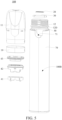
- FIG. 5 and FIG. 6 are respectively a schematic three-dimensional exploded view of the aerosol supply system 100 shown in FIG. 1 and a schematic three-dimensional view of the induction heating body 20 of the aerosol supply system 100.
- the induction heating body 20 is a flat extended heating sheet with holes.
- the induction heating body 20 may be in a flat plate shape as a whole, and is provided with a plurality of through holes 21 in a thickness direction of the induction heating body 20, so that the aerosol generated through atomization can penetrate the through holes 21 and diverge in a direction away from the capillary element 30.
- the induction heating body 20 may be made by opening holes in a sheet material, or may use a heating mesh structure having meshes.
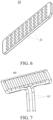
- FIG. 7 is a schematic three-dimensional view of the electromagnetic induction coil 60 of the aerosol supply system 100.
- the electromagnetic induction coil 60 is a coil extending in a plane.
- the electromagnetic induction coil 60 may be bent to form a substantially square structure, and is in a flat plate shape as a whole.
- two ends of the electromagnetic induction coil 60 may be connected to a wire pin 61, to be conductively connected to a battery 80 in the power supply assembly 100B.
- the electromagnetic induction coil 60 is arranged in a plane extending shape, to facilitate placement and positioning of the electromagnetic induction coil 60.
- the aerosol supply system 100 includes an airflow channel, and a part of the airflow channel guides airflow to bypass or penetrate the capillary element 30 and reach an atomization space 45A above the induction heating body 20.
- the airflow channel as a whole may start at an air inlet end 72 of the aerosol supply system 100, and end at an air outlet end 18 of the aerosol supply system 100.
- the air inlet end 72 may be a through hole provided on a battery housing 70.
- the air outlet end 18 may be located at a mouthpiece portion 14 of a housing assembly 10.
- the airflow channel may be arranged so that after the airflow enters the aerosol supply system 100 through the air inlet end 72, the airflow is conveyed through a channel next to the capillary element 30, and then conveyed to the atomization space 45A above the induction heating body 20 through a channel higher than the capillary element 30.
- the airflow channel may be arranged so that after the airflow enters the aerosol supply system 100 through the air inlet end 72, the airflow is conveyed to the atomization space 45A above the induction heating body 20 through a channel located in the capillary element 30, which can shorten an airflow stroke. In this way, after the airflow enters the atomization space 45A, an aerosol generated through atomization in the atomization space 45A can be carried out of the air outlet end 18.
- the capillary element 30 is positioned further away from the liquid storage cavity 10A than the induction heating body 20.
- the liquid storage cavity 10 A may be defined through the housing assembly 10, the capillary element 30 is arranged at the bottom of the housing assembly 10, and the induction heating body 20 is arranged on a side of the capillary element 30 close to the liquid storage cavity 10A.
- the induction heating body 20 is stacked on an upper surface of the capillary element 30, and is pressed and fixed on the capillary element 30 through a support 40.
- both the induction heating body 20 and the capillary element 30 may be arranged in a flat plate shape, so that the induction heating body 20 can be stacked on the upper surface of the capillary element 30.
- the support 40 may be mounted in the aerosol supply system 100, and press and fix the induction heating body 20 on the capillary element 30, to achieve a fixing effect on the induction heating body 20 and the capillary element 30.
- the induction heating body 20 does not need to completely cover the upper surface of the capillary element 30, so that an exposed part of the surface of the capillary element 30 can release the aerosol. In this way, assembly of the induction heating body 20 and the capillary element 30 is also simple.
- the atomizer 100A of the aerosol supply system 100 includes the induction heating body 20 and the capillary element 30, and may further include a housing assembly 10.
- the housing assembly 10 defines the liquid storage cavity 10A, and includes a mouthpiece portion 14, a bottom end portion 15, and a smoke exhaust pipe 13.
- the bottom end portion 15 is arranged opposite to the mouthpiece portion 14, and the smoke exhaust pipe 13 extends from the mouthpiece portion 14 toward the bottom end portion 15 in the housing assembly 10.
- the capillary element 30 is located in the housing assembly 10 and arranged on the bottom end portion 15, and the induction heating body 20 is positioned closer to the smoke exhaust pipe 13 than the capillary element 30. In this way, the aerosol generated through atomization can directly enter the smoke exhaust pipe 13.
- an air inlet channel is provided on the housing assembly 10, and the air inlet channel bypasses or penetrates the capillary element 30, to guide the airflow to vicinity of the induction heating body 20.
- the air inlet channel may be the foregoing airflow channel, or may be a part of the airflow channel.
- the capillary element 30 is located between the induction heating body 20 and the bottom end portion 15 of the housing assembly 10.
- the capillary element 30 may be arranged at the bottom of the housing assembly 10, and the induction heating body 20 may be arranged on a side of the capillary element 30 close to the liquid storage cavity 10A. In this way, it is convenient to orient a heating surface of the capillary element 30 toward or close to a smoke exhaust pipe 13 of the aerosol supply system 100, so that the aerosol generated through atomization does not need to bypass the capillary element 30, but directly enters the smoke exhaust pipe 13.
- the induction heating body 20 is pressed and fixed on the capillary element 30 through a support 40.
- the support 40 is located in the housing assembly 10, and defines a first channel 44 in communication with the liquid storage cavity 10A to guide the liquid substrate to the capillary element 30 and a second channel 45 in communication with the smoke exhaust pipe 13, and at least a part of the second channel 45 is used as an atomization space 45A above the induction heating body 20.
- pressing and fixing of the induction heating body 20 and the capillary element 30 by the support 40 can be implemented, and the first channel 44 and the second channel 45 for liquid and gas communication through the support 40 can also be provided.
- an end portion of the capillary element 30 may be located below the first channel 44, so that the capillary element 30 can absorb the liquid substrate in the first channel 44.
- the support 40 includes an elastic pressing member 41 and a supporting component 42 configured to support the elastic pressing member 41.
- the elastic pressing member 41 is configured to press and fix the induction heating body 20 on a surface of the capillary element 30.
- the support 40 may further include a first sealing member 43.
- the first sealing member 43 is connected to an upper end of the supporting component 42, and the elastic pressing member 41 is connected to a lower end of the supporting component 42.
- FIG. 8 and FIG, 9 are respectively two schematic three-dimensional views of the elastic pressing member 41.
- a top end of the elastic pressing member 41 may include a clamping groove 41B, for clamping and matching with the supporting component 42; and a bottom end of the elastic pressing member 41 may include an abutting surface 41C and positioning posts 41D extending downward from the abutting surface 41C.
- the elastic pressing member 41 may press and fix the induction heating body 20 on the capillary element 30 through the abutting surface 41C.
- the elastic pressing member 41 may be made of silica gel.
- FIG. 10 is a schematic three-dimensional view of the capillary element 30.
- Positioning holes 31 may be provided at two ends of the capillary element 30, so that the positioning posts 41D of the elastic pressing member 41 can be inserted into the positioning holes 31 of the capillary element 30, to implement mounting and positioning of the capillary element 30.
- FIG. 11 and FIG. 12 are respectively two schematic three-dimensional views of the supporting component 42.
- the supporting component 42 may be made of a hard material, to provide structural support, where the lower end of the supporting component 42 may include an insertion plate 42A, for matching with the clamping groove 41B of the elastic pressing member 41; and the upper end of the supporting component 42 may include an annular wall 42B, for sleeving the first sealing member 43 thereon.
- a clamping block 42C may further be provided on a side wall of the supporting component 42, for buckling and matching with the housing assembly 10.
- FIG. 13 and FIG. 14 are respectively two three-dimensional views of the first sealing member 43.
- the first sealing member 43 may include an annular insertion groove 43A, the annular wall 42B is accommodated by the annular insertion groove 43A to mount the first sealing member 43 on the supporting component 42, and form sealing between the supporting component 42 and the housing assembly 10.
- the support 40 is arranged to include the elastic pressing member 41, the supporting component 42, and the first sealing member 43, so that elastic pressing of the induction heating body 20, necessary sealing of the liquid storage cavity 10A of the housing assembly 10, and overall structural strength of the support 40 can be implemented.
- an insertion hole 43B may be provided in the middle of the first sealing member 43, for insertion and matching of a lower end of the smoke exhaust pipe 13.
- the first sealing member 43 may be made of silica gel.
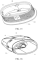
- FIG. 15 is a schematic three-dimensional view of a base 12 of the aerosol supply system 100 shown in FIG. 5 .
- An air inlet hole 16 is provided on the bottom end portion 15 of the housing assembly 10, and the air inlet hole 16 extends in a longitudinal direction, so that a port of the air inlet hole 16 is higher than an upper surface of the capillary element 30.
- a notch 41A is provided on the support 40, so that airflow output through the air inlet hole 16 reaches the atomization space 45A above the induction heating body 20 via the notch 41A.
- the housing assembly 10 may include an upper housing 11 and a base 12, and the base 12 includes the bottom end portion 15.
- the air inlet hole 16 may be provided on the base 12 of the housing assembly 10, where an upper end opening of the air inlet hole 16 is provided higher than the capillary element 30, and may further be higher than the induction heating body 20.
- the notch 41A may be provided on the elastic pressing member 41 of the support 40.
- a clamping groove 12A may be provided on a side wall of the base 12, for buckling and matching with the clamping block 42C on the side wall of the supporting component 42. Because there is no need to provide a channel of a wire or an electrode sheet, the base 12 may be directly provided with an upper opening accommodation groove for accommodating the capillary element 30, so that liquid leakage can be prevented.
- a plurality of liquid leakage storage grooves 12C may further be formed on an outer side surface of the base 12.
- the liquid leakage storage grooves 12C may be provided concave from the outer side surface of the base 12, or may be defined by a plurality of convex strips provided on the outer side surface of the base 12.
- an annular groove 12D may further be formed on the outer side surface of the base 12, and a sealing ring 50 may be embedded in the annular groove 12D, to form sealing with the upper housing 11.
- FIG. 16 is a schematic three-dimensional view of an upper housing 11 of the aerosol supply system 100 shown in FIG. 5 .
- the upper housing 11 is generally constructed into a hollow cylindrical shape, where the upper housing 11 has a mouthpiece portion 14 located at a near end and an opening at a far end, to facilitate assembly of various functional components in the upper housing 11 through the opening.
- a cross section of the far end may be a racetrack shape, an oval shape, or the like that is close to a flat shape.
- the liquid storage cavity 10A is mainly defined by the upper housing 11, and the smoke exhaust pipe 13 extends from the mouthpiece portion 14 toward the far end in the housing assembly 10.
- a clamping block 11A may be provided on an outer side of the upper housing 11 close to the far end.
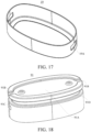
- FIG. 17 is a schematic three-dimensional view of a bottom cover 19 of the aerosol supply system 100 shown in FIG. 5 .
- the bottom cover 19 may be made of metal, and a clamping hole 19A may be provided on a side wall of the bottom cover, for buckling and matching with the clamping block 11A of the upper housing 11, to keep the base 12 in combination with the upper housing 11.
- the aerosol supply system 100 includes the power supply assembly 100B.
- the power supply assembly 100B includes a battery housing 70, a battery 80, and the electromagnetic induction coil 60, where the battery housing 70 accommodates the battery 80 and the electromagnetic induction coil 60, and the electromagnetic induction coil 60 is electrically connected to the battery 80.
- the electromagnetic induction coil 60 may be, for example, located above the battery 80.
- the battery 80 is configured to provide a current to the electromagnetic induction coil 60, so that the electromagnetic induction coil 60 generates the variable magnetic field.
- the electromagnetic induction coil 60 should be arranged as close as possible to the induction heating body 20 in the atomizer 100A, so that the induction heating body 20 is located in the electromagnetic field generated by the electromagnetic induction coil 60.
- the electromagnetic induction coil 60 and the induction heating body 20 are arranged in parallel.
- the induction heating body 20 and the electromagnetic induction coil 60 are arranged in plane extending shapes, so that the induction heating body 20 and the electromagnetic induction coil 60 can be arranged in parallel, to facilitate placement and positioning of the induction heating body 20 and the electromagnetic induction coil 60.
- the electromagnetic induction coil 60 may have another structure and arrangement.
- the electromagnetic induction coil may be constructed into a three-dimensional cylindrical spiral coil, and the electromagnetic induction coil is arranged in a circumferential direction of an accommodation cavity of the power supply assembly 100B.
- the induction heating body 20 is exactly surrounded by the cylindrical spiral coil, so that the induction heating body 20 can be located in magnetic field space.
- the battery housing 70 further defines an insertion cavity 71, and a part of the atomizer 100A may be inserted into the insertion cavity 71.
- an effective distance between the induction heating body 20 and the electromagnetic induction coil 60 may range from 2 mm to 4 mm, and is preferably about 3 mm, and a thickness of the capillary element 30 may be controlled to range from 1 mm to 1.5 mm.
- FIG. 18 is a schematic three-dimensional view of an insulation member 91 of the aerosol supply system 100 shown in FIG. 5 .
- the insulation member 91 is arranged in the battery housing 70, configured to cover the electromagnetic induction coil 60.
- a concave portion 91A may be formed on a top end of the insulation member 91, and the concave portion 91A may be used as a part of the airflow channel in the aerosol supply system 100.
- Two sides of the concave portion 91A are in communication with grooves 91B, and the grooves 91B correspond to and are in communication with the air inlet end 72 provided on the battery housing 70.
- a clamping groove 91C and an annular groove 91D may further be arranged on a side wall of the insulation member 91.
- a sealing ring 94 may be embedded in the annular groove 91D, to form sealing with the battery housing 70, thereby preventing a liquid substrate seeping from the atomizer 100A to the insertion cavity 71 from flowing to a controller 95, a sensor 96, and other components in the power supply assembly 100B.
- the sensor 96 may be configured to sense inhalation airflow generated by the atomizer 100A during inhalation, so that the controller 95 controls, based on a detection signal of the sensor 96, the battery 80 to output a current to the electromagnetic induction coil 60.
- FIG. 19 is a schematic three-dimensional view of a coil support 92 of the aerosol supply system 100.
- An accommodation groove 92A may be formed on a top end of the coil support 92, for placing the electromagnetic induction coil 60 therein.
- the power supply assembly 100B may further include a mounting support 93, where the mounting support 93 may accommodate and hold the battery 80, and may hold the coil support 92 and the electromagnetic induction coil 60 on the mounting support 93 through buckling and matching between a buckle and the clamping groove 91C of the insulation member 91.
- FIG. 20 and FIG. 21 are respectively a schematic sectional view and a schematic partial enlarged view of an aerosol supply system 100 according to another embodiment of this application.
- the aerosol supply system 100 in this embodiment is substantially the same as the foregoing aerosol supply system, and also includes an atomizer 100A and a power supply assembly 100B.
- the atomizer 100A further includes a housing assembly 10, an induction heating body 20, a capillary element 30, and a support 40.
- the power supply assembly 100B further includes an electromagnetic induction coil 60, a battery housing 70, and a battery (where this is not shown in the figure, and may refer to the battery 80 in FIG. 2 ).
- a difference between the aerosol supply system 100 in this embodiment and the foregoing aerosol supply system is that: in the aerosol supply system 100 in the embodiment shown in FIG. 20 , a bottom end portion 15 of the housing assembly 10 includes an air inlet post 17 extending through the capillary element 30, and a tail end of the air inlet post 17 is higher than an upper surface of the capillary element 30.
- the interior of the air inlet post 17 is hollow, to provide a vertical air guiding channel 17A.
- An end surface of the end of the air inlet post 17 is higher than an atomization surface of the capillary element 30, so that e-liquid can be prevented from leaking.
- a quantity of air inlet posts 17 may be one or more, for example, may be two.
- An axis of the air inlet post 17 and an axis of a smoke exhaust pipe 13 of the housing assembly 10 may be arranged to be staggered, to prevent condensate in the smoke exhaust pipe 13 from falling down on the air inlet post 17 and causing blockage.
- an end surface of the air inlet post 17 may be designed to be closed, and an air outlet hole in a radial direction may be provided on a side portion of the air inlet post 17 to be in communication with the vertical air guiding channel 17A.
- the air outlet hole is provided to be not covered by the capillary element 30, for example, oil guiding cotton, and the induction heating body 20, for example, a heating sheet, and may be close to a surface of the induction heating body 20.
- the support 40 may define a second channel 45 in communication with the smoke exhaust pipe 13, where an inner surface of the second channel 45 close to the air inlet post 17 may have an inclined surface for guiding the airflow from two sides of the atomization space 45A to the smoke exhaust pipe 13 in the middle.
- FIG. 22 and FIG. 23 are respectively two schematic three-dimensional views of the support 40 of the aerosol supply system 100 shown in FIG. 20 .
- the support 40 may include an abutting surface 41C. Therefore, the induction heating body 20 can be pressed and fixed on the capillary element 30 through the abutting surface 41C of the support 40.
- the support 40 is a second sealing member, for example, the support 40 may be made of silica gel, to have supporting and sealing properties.
- the housing assembly 10 may include an upper housing 11 and a base 12.
- FIG. 24 and FIG. 25 are respectively two three-dimensional views of the base 12 of the aerosol supply system 100 shown in FIG. 20 .
- the base 12 includes the bottom end portion 15.
- the support 40 used as the second sealing member is mounted on the base 12; and the base 12 may be inserted into a lower end opening of the upper housing 11. At least a part of the support 40 used as the second sealing member is constructed to provide sealing between the base 12 and the upper housing 11.
- a side wall 40A of the second sealing member and a side wall 12B of the base 12 enclose a third channel 46, the third channel 46 is in communication with a liquid storage cavity 10A to guide a liquid substrate to the capillary element 30, the second sealing member further includes a second channel 45, and at least a part of the second channel 45 is constructed as the atomization space 45A above the induction heating body 20.
- a clamping block 12E may further be provided on the side wall of the base 12, for buckling and matching with the upper housing 11.
- FIG. 26 is a schematic three-dimensional view of the electromagnetic induction coil 60 of the aerosol supply system 100 shown in FIG. 20 .
- the electromagnetic induction coil 60 is a spiral coil extending in a plane.
- the electromagnetic induction coil 60 may be wound or spiraled to form a substantially circular or oval structure, and is in a flat plate shape as a whole.
- two ends of the electromagnetic induction coil 60 may be connected to a wire pin 61, to be conductively connected to the battery in the power supply assembly 100B.
- the electromagnetic induction coil 60 is arranged in a plane extending shape, to facilitate placement and positioning of the electromagnetic induction coil 60.
- an aerosol supply system 100 When an aerosol supply system 100 needs to be used for inhalation, first, a power switch of a power supply assembly 100B may be turned on, so that a battery 80 supplies power to an electromagnetic induction coil 60; and then, when a user performs inhalation on a mouthpiece portion 14 of an atomizer 100A, a controller 95 of the aerosol supply system 100 may start the power supply assembly 100B and the atomizer 100 A to operate based on an inhalation action, to generate an aerosol for the user to inhale at last.
- a liquid substrate from a liquid storage cavity 10A is heated and atomized through an induction heating body 20 to form the aerosol, external air may sequentially flow through an air inlet end 72, a groove 91B, a concave portion 91A, an air inlet hole 16, and a notch 41A (or an air guiding channel 17A), to be conveyed above an atomization surface of a capillary element 30, and the formed aerosol is carried out of a smoke exhaust pipe 13 through a second channel 45.
Landscapes
- Physics & Mathematics (AREA)
- Electromagnetism (AREA)
- Special Spraying Apparatus (AREA)
Abstract
Description
- This application claims priority to
Chinese Patent Application No. 202111654469.3, filed with the China National Intellectual Property Administration on December 30, 2021 - This application relates to the field of electronic atomization technologies, and in particular, to an aerosol supply system and an atomizer of the aerosol supply system.
- An aerosol supply system is an electronic product that heats and atomizes a liquid substrate such as e-liquid or liquid medicine into an aerosol for inhalation.
- The aerosol supply system may include an atomizer and a power supply assembly, where the power supply assembly is configured to supply power to the atomizer; and the atomizer may include an atomization core assembly and an atomization chamber, where the atomization core assembly is configured to generate heat when powered on to atomize the liquid substrate, and the atomization chamber is for supplying a liquid substrate to be heated and atomized to the atomization core assembly.
- The aerosol supply system usually uses a porous ceramic body as a capillary liquid guiding element for absorbing the liquid substrate, and uses a heating element arranged on an atomization surface of the porous ceramic body to heat at least a part of the liquid substrate in the porous ceramic body to generate an aerosol.
- Currently, in an e-liquid atomization technology, ceramic is mostly used to generate heat. In some solutions, a ceramic heating surface is provided upward. In other words, the heating surface is toward a mouthpiece of an atomization device. This needs an electrode pin to be bent at an angle, so that the electrode pin is connected to an electrode of a heating element. However, it is difficult to control the bending angle and elastic force of the electrode pin, making electrode assembly inconvenient, and it is also difficult to control elastic force of the electrode when the electrode is in contact with a ceramic surface. In addition, a ceramic core needs to be sealed with silica gel, so that the ceramic core is sealed and assembled in an atomization seat. However, this makes assembly inconvenient, and a sealing effect is not good, which may result in liquid leakage. In addition, costs of using the ceramic core to generate heat are high. Further, inlet air needs to bypass two side walls of a fixed seat of the ceramic core, making an airflow stroke long.
- This application aims to provide an aerosol supply system and an atomizer thereof, to resolve a technical problem that an existing aerosol supply system and an atomizer thereof are not easy to assemble.
- The following technical solution is used to resolve the technical problem in this application: An aerosol supply system is provided, configured to atomize a liquid substrate to generate an aerosol, where the aerosol supply system includes: a liquid storage cavity, an electromagnetic induction coil, an induction heating body, and a capillary element. The liquid storage cavity is for storing the liquid substrate. The electromagnetic induction coil is configured to generate a variable magnetic field. The induction heating body is configured to induce heating in the variable magnetic field. The capillary element is arranged in contact with the induction heating body, and configured to receive and store the liquid substrate from the liquid storage cavity and convey the liquid substrate to vicinity of the induction heating body. The capillary element is positioned between the electromagnetic induction coil and the induction heating body.
- In a preferred embodiment, the induction heating body is a flat extended heating sheet with holes; and/or the electromagnetic induction coil is a coil extending in a plane.
- In a preferred embodiment, the aerosol supply system includes an airflow channel, and a part of the airflow channel guides airflow to bypass or penetrate the capillary element and reach an atomization space above the induction heating body.
- In a preferred embodiment, the capillary element is positioned further away from the liquid storage cavity than the induction heating body.
- In a preferred embodiment, the induction heating body is stacked on an upper surface of the capillary element, and is pressed and fixed on the capillary element through a support.
- In a preferred embodiment, the aerosol supply system includes a housing assembly, the housing assembly defines the liquid storage cavity and includes a mouthpiece portion, a bottom end portion, and a smoke exhaust pipe, the bottom end portion is arranged opposite to the mouthpiece portion, and the smoke exhaust pipe extends from the mouthpiece portion toward the bottom end portion in the housing assembly; and the capillary element is located in the housing assembly and arranged on the bottom end portion, and the induction heating body is positioned closer to the smoke exhaust pipe than the capillary element.
- In a preferred embodiment, the aerosol supply system further includes a support located in the housing assembly, the support defines a first channel in communication with the liquid storage cavity to guide the liquid substrate to the capillary element and a second channel in communication with the smoke exhaust pipe, and at least a part of the second channel is used as an atomization space above the induction heating body.
- In a preferred embodiment, the support includes an elastic pressing member and a supporting component configured to support the elastic pressing member; and the elastic pressing member is configured to press and fix the induction heating body on a surface of the capillary element.
- In a preferred embodiment, an air inlet hole is provided on the bottom end portion of the housing assembly, and the air inlet hole extends in a longitudinal direction, so that a port of the air inlet hole is higher than an upper surface of the capillary element; and a notch is provided on the support, so that airflow output through the air inlet hole reaches the atomization space above the induction heating body via the notch.
- In a preferred embodiment, the bottom end portion of the housing assembly includes an air inlet post extending through the capillary element, and the interior of the air inlet post is hollow, and a tail end of the air inlet post is higher than an upper surface of the capillary element.
- In a preferred embodiment, the induction heating body is pressed and fixed on the capillary element through a support; the housing assembly includes an upper housing and a base, the base includes the bottom end portion, the support is mounted on the base and is used as a second sealing member, and at least a part of the second sealing member is constructed to provide sealing between the base and the upper housing; and the second sealing member and the base enclose a third channel, the third channel is in communication with the liquid storage cavity to guide the liquid substrate to the capillary element, the second sealing member further includes a second channel in communication with the smoke exhaust pipe, and at least a part of the second channel is constructed as an atomization space above the induction heating body.
- In a preferred embodiment, the aerosol supply system includes a power supply assembly, the power supply assembly includes a battery housing, a battery, and the electromagnetic induction coil, the battery housing accommodates the battery and the electromagnetic induction coil, and the electromagnetic induction coil is electrically connected to the battery.
- In a preferred embodiment, the electromagnetic induction coil and the induction heating body are arranged in parallel.
- The following technical solution is used to resolve the technical problem in this application: An atomizer of an aerosol supply system is provided, where the atomizer includes: a housing assembly, defining a liquid storage cavity for storing a liquid substrate, and including a mouthpiece portion, a bottom end portion, and a smoke exhaust pipe, where the bottom end portion is arranged opposite to the mouthpiece portion, and the smoke exhaust pipe extends from the mouthpiece portion toward the bottom end portion in the housing assembly; an induction heating body, configured to be capable of inducing heating in a varying magnetic field, to heat a part of the liquid substrate to generate an aerosol; and a capillary element, arranged in contact with the induction heating body, and configured to receive and store the liquid substrate from the liquid storage cavity and convey the liquid substrate to vicinity of the induction heating body, where the induction heating body is positioned closer to the smoke exhaust pipe than the capillary element.
- In a preferred embodiment, the capillary element is located between the induction heating body and the bottom end portion of the housing assembly.
- In a preferred embodiment, the induction heating body is stacked on an upper surface of the capillary element, and is pressed and fixed on the capillary element through a support.
- In a preferred embodiment, the capillary element is arranged in a flat plate shape, and a thickness of the capillary element ranges from 1 mm to 1.5 mm.
- In a preferred embodiment, an air inlet channel is provided on the housing assembly, and the air inlet channel bypasses or penetrates the capillary element, to guide airflow to vicinity of the induction heating body.
- Beneficial effects of this application are as follows: In the aerosol supply system and the atomizer in embodiments, an electromagnetic induction coil is used to generate a variable magnetic field to perform induction heating on an induction heating body, so that a conductive structure, for example, an electrode pin, does not need to be arranged for conductive connection to the heating body. This makes it easy and convenient to assemble an atomizer including the induction heating body and a capillary element in the aerosol supply system, and avoids difficulty in bending and assembling an electrode elastic sheet. In addition, because the induction heating body does not need to be connected to a wire, the induction heating body can be arranged further away from the electromagnetic induction coil than the capillary element. In this way, it is convenient to orient a heating surface of the capillary element toward or close to a smoke exhaust pipe of the aerosol supply system, so that an aerosol generated through atomization does not need to bypass the capillary element, but directly enters the smoke exhaust pipe, and is inhaled by a user.
- One or more embodiments are exemplarily described with reference to corresponding figures in the accompanying drawings, and the exemplary descriptions do not constitute a limitation on the embodiments. Elements in the accompanying drawings that have same reference numerals are represented as similar elements, and unless otherwise particularly stated, the figures in the accompanying drawings are not drawn to scale.
-
FIG. 1 is a schematic three-dimensional assembly view of an aerosol supply system according to an embodiment of this application; -
FIG. 2 is a schematic sectional view of the aerosol supply system shown inFIG. 1 ; -
FIG. 3 is a schematic enlarged view of Part I inFIG. 2 ; -
FIG. 4 is another schematic sectional view of the aerosol supply system shown inFIG. 1 ; -
FIG. 5 is a schematic three-dimensional exploded view of the aerosol supply system shown inFIG. 1 ; -
FIG. 6 is a schematic three-dimensional view of an induction heating body of the aerosol supply system shown inFIG. 5 ; -
FIG. 7 is a schematic three-dimensional view of an electromagnetic induction coil of the aerosol supply system shown inFIG. 5 ; -
FIG. 8 is a schematic three-dimensional view an elastic pressing member of the aerosol supply system shown inFIG. 5 ; -
FIG. 9 is another schematic three-dimensional view of the elastic pressing member shown inFIG. 8 ; -
FIG. 10 is a schematic three-dimensional view of a capillary element of the aerosol supply system shown inFIG. 5 ; -
FIG. 11 is a schematic three-dimensional view of a supporting component of the aerosol supply system shown inFIG. 5 ; -
FIG. 12 is another schematic three-dimensional view of a supporting component shown inFIG. 9 ; -
FIG. 13 is a schematic sectional view of a first sealing member of the aerosol supply system shown inFIG. 5 ; -
FIG. 14 is another schematic three-dimensional view of the first sealing member shown inFIG. 13 ; -
FIG. 15 is a schematic three-dimensional view of a base of the aerosol supply system shown inFIG. 5 ; -
FIG. 16 is a schematic three-dimensional view of an upper housing of the aerosol supply system shown inFIG. 5 ; -
FIG. 17 is a schematic three-dimensional view of a bottom cover of the aerosol supply system shown inFIG. 5 ; -
FIG. 18 is a schematic three-dimensional view of an insulation member of the aerosol supply system shown inFIG. 5 ; -
FIG. 19 is a schematic three-dimensional view of a coil support of the aerosol supply system shown inFIG. 5 ; -
FIG. 20 is a schematic sectional view of an aerosol supply system according to another embodiment of this application; -
FIG. 21 is a schematic enlarged view of Part II inFIG. 20 ; -
FIG. 22 is a schematic three-dimensional view of a support of the aerosol supply system shown inFIG. 20 ; -
FIG. 23 is another schematic three-dimensional view of the support shown inFIG. 22 ; -
FIG. 24 is a schematic three-dimensional view of a base of the aerosol supply system shown inFIG. 20 ; -
FIG. 25 is another schematic three-dimensional view of a base shown inFIG. 22 ; and -
FIG. 26 is a schematic three-dimensional view of an electromagnetic induction coil of the aerosol supply system shown inFIG. 20 . - For ease of understanding of this application, this application is described below in more detail with reference to the accompanying drawings and specific embodiments. It should be noted that, when an element is expressed as "being fixed to" another element, the element may be directly on the another element, or one or more intermediate elements may exist between the element and the another element. When an element is expressed as "being connected to" another element, the element may be directly connected to the another element, or one or more intermediate elements may exist between the element and the another element. Terms "vertical", "horizontal", "left", "right", "inner", "outside", and similar expressions used in this specification are merely used for an illustrative purpose.
- Unless otherwise defined, meanings of all technical and scientific terms used in this specification are the same as that usually understood by a person skilled in the technical field to which this application belongs. Terms used in the specification of this application are merely intended to describe objectives of the specific embodiments, but are not intended to limit this application. A term "and/or" used in this specification includes any or all combinations of one or more related listed items.
- In addition, technical features involved in different embodiments of this application described below may be combined together if there is no conflict.
-
FIG. 1 is a schematic three-dimensional assembly view of anaerosol supply system 100 according to an embodiment of this application. Theaerosol supply system 100 is configured to atomize a liquid substrate to generate an aerosol, where theaerosol supply system 100 may include: anatomizer 100A storing and atomizing the liquid substrate to generate the aerosol; and apower supply assembly 100B supplying heating energy to theatomizer 100A. The liquid substrate may be liquid such as e-liquid or liquid medicine. The liquid substrate may also be referred to as liquid, atomization may also be referred to as vaporization, and the aerosol may also be referred to as flue gas, aerial fog, or atomized gas. -
FIG. 2 andFIG. 4 are two schematic sectional views of theaerosol supply system 100 shown inFIG. 1 , andFIG. 3 is a schematic enlarged view of Part I inFIG. 2 . As shown in the figures, in an embodiment, theaerosol supply system 100 may include aliquid storage cavity 10A, aninduction heating body 20, acapillary element 30, and anelectromagnetic induction coil 60. Theliquid storage cavity 10A is an accommodation space defined in theaerosol supply system 100, for storing the liquid substrate and supplying the liquid substrate to thecapillary element 30. Theelectromagnetic induction coil 60 may be arranged by using a wire, and is configured to generate a variable magnetic field when theelectromagnetic induction coil 60 is powered on. Theinduction heating body 20 may be arranged in the variable magnetic field generated by theelectromagnetic induction coil 60, so that theinduction heating body 20 can be penetrated by the varying magnetic field to generate heat, to heat the liquid substrate. Thecapillary element 30 is arranged in contact with theinduction heating body 20, and is configured to receive and store the liquid substrate from theliquid storage cavity 10A via a capillary space of thecapillary element 30, and convey the liquid substrate to vicinity of theinduction heating body 20 through capillary action, so that thecapillary element 30 can continuously supply the liquid substrate toward theinduction heating body 20 as theinduction heating body 20 heats up the liquid substrate close to theinduction heating body 20 in thecapillary element 30. Thecapillary element 30 is positioned between theelectromagnetic induction coil 60 and theinduction heating body 20. For example, thecapillary element 30 may be prepared by a material having a capillary channel or pores, for example, a hard or rigid capillary structure such as fibrous cotton, a porous ceramic body, a glass fiber rope, porous glass ceramic, or porous glass. Thecapillary element 30 is in fluid communication with theliquid storage cavity 10A, to absorb the liquid substrate conveyed from theliquid storage cavity 10A. For example, oil guiding cotton may be used as thecapillary element 30 for oil guiding. Because the oil guiding cotton may have a sealing and oil locking capability, theinduction heating body 20 may be placed on thecapillary element 30, so that an atomization area is increased, and an atomization effect is better. - In the
aerosol supply system 100 in this embodiment, anelectromagnetic induction coil 60 is used to generate a variable magnetic field to perform induction heating on aninduction heating body 20, so that a conductive structure, for example, an electrode pin, does not need to be arranged for conductive connection to the heating body. This makes it easy and convenient to assemble an atomizer including theinduction heating body 20 and acapillary element 30 in the aerosol supply system, and avoids difficulty in bending and assembling an electrode elastic sheet. In addition, because theinduction heating body 20 does not need to be connected to a wire, the induction heating body can be arranged further away from theelectromagnetic induction coil 60 than thecapillary element 30. In this way, it is convenient to orient a heating surface of thecapillary element 30 toward or close to asmoke exhaust pipe 13 of theaerosol supply system 100, so that an aerosol generated through atomization does not need to bypass thecapillary element 30, but directly enters thesmoke exhaust pipe 13, and is inhaled by a user. -
FIG. 5 andFIG. 6 are respectively a schematic three-dimensional exploded view of theaerosol supply system 100 shown inFIG. 1 and a schematic three-dimensional view of theinduction heating body 20 of theaerosol supply system 100. As shown in the figures, in an optional embodiment, theinduction heating body 20 is a flat extended heating sheet with holes. For example, theinduction heating body 20 may be in a flat plate shape as a whole, and is provided with a plurality of throughholes 21 in a thickness direction of theinduction heating body 20, so that the aerosol generated through atomization can penetrate the throughholes 21 and diverge in a direction away from thecapillary element 30. Theinduction heating body 20 may be made by opening holes in a sheet material, or may use a heating mesh structure having meshes. -
FIG. 7 is a schematic three-dimensional view of theelectromagnetic induction coil 60 of theaerosol supply system 100. As shown inFIG. 7 , in an optional embodiment, theelectromagnetic induction coil 60 is a coil extending in a plane. Theelectromagnetic induction coil 60 may be bent to form a substantially square structure, and is in a flat plate shape as a whole. In addition, two ends of theelectromagnetic induction coil 60 may be connected to awire pin 61, to be conductively connected to abattery 80 in thepower supply assembly 100B. Theelectromagnetic induction coil 60 is arranged in a plane extending shape, to facilitate placement and positioning of theelectromagnetic induction coil 60. - In an optional embodiment, as shown in
FIG. 2 to FIG. 4 , theaerosol supply system 100 includes an airflow channel, and a part of the airflow channel guides airflow to bypass or penetrate thecapillary element 30 and reach anatomization space 45A above theinduction heating body 20. For example, the airflow channel as a whole may start at anair inlet end 72 of theaerosol supply system 100, and end at an air outlet end 18 of theaerosol supply system 100. Theair inlet end 72 may be a through hole provided on abattery housing 70. Theair outlet end 18 may be located at amouthpiece portion 14 of ahousing assembly 10. The airflow channel may be arranged so that after the airflow enters theaerosol supply system 100 through theair inlet end 72, the airflow is conveyed through a channel next to thecapillary element 30, and then conveyed to theatomization space 45A above theinduction heating body 20 through a channel higher than thecapillary element 30. Alternatively, the airflow channel may be arranged so that after the airflow enters theaerosol supply system 100 through theair inlet end 72, the airflow is conveyed to theatomization space 45A above theinduction heating body 20 through a channel located in thecapillary element 30, which can shorten an airflow stroke. In this way, after the airflow enters theatomization space 45A, an aerosol generated through atomization in theatomization space 45A can be carried out of theair outlet end 18. - In an optional embodiment, as shown in
FIG. 2 to FIG. 4 , thecapillary element 30 is positioned further away from theliquid storage cavity 10A than theinduction heating body 20. For example, theliquid storage cavity 10 A may be defined through thehousing assembly 10, thecapillary element 30 is arranged at the bottom of thehousing assembly 10, and theinduction heating body 20 is arranged on a side of thecapillary element 30 close to theliquid storage cavity 10A. In this way, it is still convenient to orient a heating surface of thecapillary element 30 toward or close to asmoke exhaust pipe 13 of theaerosol supply system 100, so that the aerosol generated through atomization does not need to bypass thecapillary element 30, but directly enters thesmoke exhaust pipe 13. - In an optional embodiment, as shown in
FIG. 2 to FIG. 4 , theinduction heating body 20 is stacked on an upper surface of thecapillary element 30, and is pressed and fixed on thecapillary element 30 through asupport 40. For example, both theinduction heating body 20 and thecapillary element 30 may be arranged in a flat plate shape, so that theinduction heating body 20 can be stacked on the upper surface of thecapillary element 30. Thesupport 40 may be mounted in theaerosol supply system 100, and press and fix theinduction heating body 20 on thecapillary element 30, to achieve a fixing effect on theinduction heating body 20 and thecapillary element 30. Theinduction heating body 20 does not need to completely cover the upper surface of thecapillary element 30, so that an exposed part of the surface of thecapillary element 30 can release the aerosol. In this way, assembly of theinduction heating body 20 and thecapillary element 30 is also simple. - In an optional embodiment, as shown in
FIG. 2 ,FIG. 3 , andFIG. 5 , theatomizer 100A of theaerosol supply system 100 includes theinduction heating body 20 and thecapillary element 30, and may further include ahousing assembly 10. Thehousing assembly 10 defines theliquid storage cavity 10A, and includes amouthpiece portion 14, abottom end portion 15, and asmoke exhaust pipe 13. Thebottom end portion 15 is arranged opposite to themouthpiece portion 14, and thesmoke exhaust pipe 13 extends from themouthpiece portion 14 toward thebottom end portion 15 in thehousing assembly 10. Thecapillary element 30 is located in thehousing assembly 10 and arranged on thebottom end portion 15, and theinduction heating body 20 is positioned closer to thesmoke exhaust pipe 13 than thecapillary element 30. In this way, the aerosol generated through atomization can directly enter thesmoke exhaust pipe 13. - In an optional embodiment, as shown in
FIG. 2 ,FIG. 3 ,FIG. 4 , andFIG. 5 , an air inlet channel is provided on thehousing assembly 10, and the air inlet channel bypasses or penetrates thecapillary element 30, to guide the airflow to vicinity of theinduction heating body 20. The air inlet channel may be the foregoing airflow channel, or may be a part of the airflow channel. - In an optional embodiment, as shown in
FIG. 2 to FIG. 4 , thecapillary element 30 is located between theinduction heating body 20 and thebottom end portion 15 of thehousing assembly 10. For example, thecapillary element 30 may be arranged at the bottom of thehousing assembly 10, and theinduction heating body 20 may be arranged on a side of thecapillary element 30 close to theliquid storage cavity 10A. In this way, it is convenient to orient a heating surface of thecapillary element 30 toward or close to asmoke exhaust pipe 13 of theaerosol supply system 100, so that the aerosol generated through atomization does not need to bypass thecapillary element 30, but directly enters thesmoke exhaust pipe 13. - In an optional embodiment, as shown in
FIG. 2 to FIG. 4 , theinduction heating body 20 is pressed and fixed on thecapillary element 30 through asupport 40. Thesupport 40 is located in thehousing assembly 10, and defines afirst channel 44 in communication with theliquid storage cavity 10A to guide the liquid substrate to thecapillary element 30 and asecond channel 45 in communication with thesmoke exhaust pipe 13, and at least a part of thesecond channel 45 is used as anatomization space 45A above theinduction heating body 20. In this way, pressing and fixing of theinduction heating body 20 and thecapillary element 30 by thesupport 40 can be implemented, and thefirst channel 44 and thesecond channel 45 for liquid and gas communication through thesupport 40 can also be provided. In addition, an end portion of thecapillary element 30 may be located below thefirst channel 44, so that thecapillary element 30 can absorb the liquid substrate in thefirst channel 44. - In an optional embodiment, as shown in
FIG. 3 andFIG. 5 , thesupport 40 includes an elastic pressingmember 41 and a supportingcomponent 42 configured to support the elastic pressingmember 41. The elastic pressingmember 41 is configured to press and fix theinduction heating body 20 on a surface of thecapillary element 30. In addition, thesupport 40 may further include a first sealingmember 43. Thefirst sealing member 43 is connected to an upper end of the supportingcomponent 42, and the elastic pressingmember 41 is connected to a lower end of the supportingcomponent 42. - For example,
FIG. 8 and FIG, 9 are respectively two schematic three-dimensional views of the elastic pressingmember 41. A top end of the elastic pressingmember 41 may include a clampinggroove 41B, for clamping and matching with the supportingcomponent 42; and a bottom end of the elastic pressingmember 41 may include anabutting surface 41C andpositioning posts 41D extending downward from the abuttingsurface 41C. The elastic pressingmember 41 may press and fix theinduction heating body 20 on thecapillary element 30 through theabutting surface 41C. For example, the elastic pressingmember 41 may be made of silica gel. - In addition,
FIG. 10 is a schematic three-dimensional view of thecapillary element 30. Positioning holes 31 may be provided at two ends of thecapillary element 30, so that the positioning posts 41D of the elastic pressingmember 41 can be inserted into the positioning holes 31 of thecapillary element 30, to implement mounting and positioning of thecapillary element 30. - For example,
FIG. 11 and FIG. 12 are respectively two schematic three-dimensional views of the supportingcomponent 42. The supportingcomponent 42 may be made of a hard material, to provide structural support, where the lower end of the supportingcomponent 42 may include aninsertion plate 42A, for matching with the clampinggroove 41B of the elastic pressingmember 41; and the upper end of the supportingcomponent 42 may include anannular wall 42B, for sleeving the first sealingmember 43 thereon. Aclamping block 42C may further be provided on a side wall of the supportingcomponent 42, for buckling and matching with thehousing assembly 10. - For example,
FIG. 13 and FIG. 14 are respectively two three-dimensional views of the first sealingmember 43. Thefirst sealing member 43 may include anannular insertion groove 43A, theannular wall 42B is accommodated by theannular insertion groove 43A to mount the first sealingmember 43 on the supportingcomponent 42, and form sealing between the supportingcomponent 42 and thehousing assembly 10. Thesupport 40 is arranged to include the elastic pressingmember 41, the supportingcomponent 42, and the first sealingmember 43, so that elastic pressing of theinduction heating body 20, necessary sealing of theliquid storage cavity 10A of thehousing assembly 10, and overall structural strength of thesupport 40 can be implemented. In addition, aninsertion hole 43B may be provided in the middle of the first sealingmember 43, for insertion and matching of a lower end of thesmoke exhaust pipe 13. For example, the first sealingmember 43 may be made of silica gel. - In an optional embodiment, as shown in
FIG. 2 ,FIG. 3 ,FIG. 5 , andFIG. 15, FIG. 15 is a schematic three-dimensional view of abase 12 of theaerosol supply system 100 shown inFIG. 5 . Anair inlet hole 16 is provided on thebottom end portion 15 of thehousing assembly 10, and theair inlet hole 16 extends in a longitudinal direction, so that a port of theair inlet hole 16 is higher than an upper surface of thecapillary element 30. Anotch 41A is provided on thesupport 40, so that airflow output through theair inlet hole 16 reaches theatomization space 45A above theinduction heating body 20 via thenotch 41A. For example, thehousing assembly 10 may include anupper housing 11 and abase 12, and thebase 12 includes thebottom end portion 15. Theair inlet hole 16 may be provided on thebase 12 of thehousing assembly 10, where an upper end opening of theair inlet hole 16 is provided higher than thecapillary element 30, and may further be higher than theinduction heating body 20. Thenotch 41A may be provided on the elastic pressingmember 41 of thesupport 40. In addition, a clampinggroove 12A may be provided on a side wall of thebase 12, for buckling and matching with theclamping block 42C on the side wall of the supportingcomponent 42. Because there is no need to provide a channel of a wire or an electrode sheet, thebase 12 may be directly provided with an upper opening accommodation groove for accommodating thecapillary element 30, so that liquid leakage can be prevented. - In addition, as shown in
FIG. 15 , a plurality of liquidleakage storage grooves 12C may further be formed on an outer side surface of thebase 12. The liquidleakage storage grooves 12C may be provided concave from the outer side surface of thebase 12, or may be defined by a plurality of convex strips provided on the outer side surface of thebase 12. Through forming of the liquidleakage storage grooves 12C, liquid leaking to the outer side surface of the base 12 can be absorbed and stored through the liquidleakage storage grooves 12C, for example, through capillary action, to limit flow of the leaked liquid. As shown inFIG. 5 , anannular groove 12D may further be formed on the outer side surface of thebase 12, and a sealingring 50 may be embedded in theannular groove 12D, to form sealing with theupper housing 11. - In an optional embodiment, as shown in
FIG. 2 ,FIG. 3 ,FIG. 4 ,FIG. 5 , andFIG. 16, FIG. 16 is a schematic three-dimensional view of anupper housing 11 of theaerosol supply system 100 shown inFIG. 5 . Theupper housing 11 is generally constructed into a hollow cylindrical shape, where theupper housing 11 has amouthpiece portion 14 located at a near end and an opening at a far end, to facilitate assembly of various functional components in theupper housing 11 through the opening. A cross section of the far end may be a racetrack shape, an oval shape, or the like that is close to a flat shape. Theliquid storage cavity 10A is mainly defined by theupper housing 11, and thesmoke exhaust pipe 13 extends from themouthpiece portion 14 toward the far end in thehousing assembly 10. Aclamping block 11A may be provided on an outer side of theupper housing 11 close to the far end. - In an optional embodiment, as shown in
FIG. 3 ,FIG. 4 ,FIG. 5 ,FIG. 16 , andFIG. 17, FIG. 17 is a schematic three-dimensional view of abottom cover 19 of theaerosol supply system 100 shown inFIG. 5 . Thebottom cover 19 may be made of metal, and aclamping hole 19A may be provided on a side wall of the bottom cover, for buckling and matching with theclamping block 11A of theupper housing 11, to keep the base 12 in combination with theupper housing 11. - In an optional embodiment, as shown in
FIG. 1 andFIG. 2 , theaerosol supply system 100 includes thepower supply assembly 100B. Thepower supply assembly 100B includes abattery housing 70, abattery 80, and theelectromagnetic induction coil 60, where thebattery housing 70 accommodates thebattery 80 and theelectromagnetic induction coil 60, and theelectromagnetic induction coil 60 is electrically connected to thebattery 80. Theelectromagnetic induction coil 60 may be, for example, located above thebattery 80. Thebattery 80 is configured to provide a current to theelectromagnetic induction coil 60, so that theelectromagnetic induction coil 60 generates the variable magnetic field. Theelectromagnetic induction coil 60 should be arranged as close as possible to theinduction heating body 20 in theatomizer 100A, so that theinduction heating body 20 is located in the electromagnetic field generated by theelectromagnetic induction coil 60. - In an optional embodiment, as shown in
FIG. 3 , theelectromagnetic induction coil 60 and theinduction heating body 20 are arranged in parallel. Theinduction heating body 20 and theelectromagnetic induction coil 60 are arranged in plane extending shapes, so that theinduction heating body 20 and theelectromagnetic induction coil 60 can be arranged in parallel, to facilitate placement and positioning of theinduction heating body 20 and theelectromagnetic induction coil 60. - In some other embodiments, the
electromagnetic induction coil 60 may have another structure and arrangement. For example, the electromagnetic induction coil may be constructed into a three-dimensional cylindrical spiral coil, and the electromagnetic induction coil is arranged in a circumferential direction of an accommodation cavity of thepower supply assembly 100B. When a cartridge is inserted into the accommodation cavity, theinduction heating body 20 is exactly surrounded by the cylindrical spiral coil, so that theinduction heating body 20 can be located in magnetic field space. - In an optional embodiment, as shown in
FIG. 2 andFIG. 5 , thebattery housing 70 further defines aninsertion cavity 71, and a part of theatomizer 100A may be inserted into theinsertion cavity 71. - Further, to ensure induction heating generation efficiency, when the
atomizer 100A in a form of the cartridge is placed into theinsertion cavity 71, a distance between the flatinduction heating body 20 and theelectromagnetic induction coil 60 extending in a plane should be as small as possible, and considering that thecapillary element 30 in the middle needs to have an oil storage capacity and an oil locking capability, thecapillary element 30 cannot be too thin. For example, to ensure high heating efficiency, an effective distance between theinduction heating body 20 and theelectromagnetic induction coil 60 may range from 2 mm to 4 mm, and is preferably about 3 mm, and a thickness of thecapillary element 30 may be controlled to range from 1 mm to 1.5 mm. - In an optional embodiment, as shown in
FIG. 2 ,FIG. 3 ,FIG. 4 , andFIG. 18, FIG. 18 is a schematic three-dimensional view of aninsulation member 91 of theaerosol supply system 100 shown inFIG. 5 . Theinsulation member 91 is arranged in thebattery housing 70, configured to cover theelectromagnetic induction coil 60. Aconcave portion 91A may be formed on a top end of theinsulation member 91, and theconcave portion 91A may be used as a part of the airflow channel in theaerosol supply system 100. Two sides of theconcave portion 91A are in communication withgrooves 91B, and thegrooves 91B correspond to and are in communication with theair inlet end 72 provided on thebattery housing 70. A clampinggroove 91C and anannular groove 91D may further be arranged on a side wall of theinsulation member 91. A sealingring 94 may be embedded in theannular groove 91D, to form sealing with thebattery housing 70, thereby preventing a liquid substrate seeping from theatomizer 100A to theinsertion cavity 71 from flowing to acontroller 95, asensor 96, and other components in thepower supply assembly 100B. Thesensor 96 may be configured to sense inhalation airflow generated by theatomizer 100A during inhalation, so that thecontroller 95 controls, based on a detection signal of thesensor 96, thebattery 80 to output a current to theelectromagnetic induction coil 60. - In an optional embodiment, as shown in
FIG. 2 ,FIG. 3 , andFIG. 19, FIG. 19 is a schematic three-dimensional view of acoil support 92 of theaerosol supply system 100. Anaccommodation groove 92A may be formed on a top end of thecoil support 92, for placing theelectromagnetic induction coil 60 therein. Again, as shown inFIG. 2 , thepower supply assembly 100B may further include a mountingsupport 93, where the mountingsupport 93 may accommodate and hold thebattery 80, and may hold thecoil support 92 and theelectromagnetic induction coil 60 on the mountingsupport 93 through buckling and matching between a buckle and the clampinggroove 91C of theinsulation member 91. -
FIG. 20 andFIG. 21 are respectively a schematic sectional view and a schematic partial enlarged view of anaerosol supply system 100 according to another embodiment of this application. Theaerosol supply system 100 in this embodiment is substantially the same as the foregoing aerosol supply system, and also includes anatomizer 100A and apower supply assembly 100B. Theatomizer 100A further includes ahousing assembly 10, aninduction heating body 20, acapillary element 30, and asupport 40. Thepower supply assembly 100B further includes anelectromagnetic induction coil 60, abattery housing 70, and a battery (where this is not shown in the figure, and may refer to thebattery 80 inFIG. 2 ). - A difference between the
aerosol supply system 100 in this embodiment and the foregoing aerosol supply system is that: in theaerosol supply system 100 in the embodiment shown inFIG. 20 , abottom end portion 15 of thehousing assembly 10 includes anair inlet post 17 extending through thecapillary element 30, and a tail end of theair inlet post 17 is higher than an upper surface of thecapillary element 30. The interior of theair inlet post 17 is hollow, to provide a verticalair guiding channel 17A. Through arrangement of theair inlet post 17 in this way, airflow can be directly conveyed upward and enter anatomization space 45A above theinduction heating body 20, which can shorten an airflow stroke. An end surface of the end of theair inlet post 17 is higher than an atomization surface of thecapillary element 30, so that e-liquid can be prevented from leaking. - In some embodiments, a quantity of air inlet posts 17 may be one or more, for example, may be two. An axis of the
air inlet post 17 and an axis of asmoke exhaust pipe 13 of thehousing assembly 10 may be arranged to be staggered, to prevent condensate in thesmoke exhaust pipe 13 from falling down on theair inlet post 17 and causing blockage. - In some other embodiments, an end surface of the
air inlet post 17 may be designed to be closed, and an air outlet hole in a radial direction may be provided on a side portion of theair inlet post 17 to be in communication with the verticalair guiding channel 17A. The air outlet hole is provided to be not covered by thecapillary element 30, for example, oil guiding cotton, and theinduction heating body 20, for example, a heating sheet, and may be close to a surface of theinduction heating body 20. - In some other embodiments, the
support 40 may define asecond channel 45 in communication with thesmoke exhaust pipe 13, where an inner surface of thesecond channel 45 close to theair inlet post 17 may have an inclined surface for guiding the airflow from two sides of theatomization space 45A to thesmoke exhaust pipe 13 in the middle. - In some embodiments, as shown in
FIG. 20 ,FIG. 22 , andFIG. 23 ,FIG. 22 andFIG. 23 are respectively two schematic three-dimensional views of thesupport 40 of theaerosol supply system 100 shown inFIG. 20 . Thesupport 40 may include anabutting surface 41C. Therefore, theinduction heating body 20 can be pressed and fixed on thecapillary element 30 through theabutting surface 41C of thesupport 40. Thesupport 40 is a second sealing member, for example, thesupport 40 may be made of silica gel, to have supporting and sealing properties. - The
housing assembly 10 may include anupper housing 11 and abase 12.FIG. 24 andFIG. 25 are respectively two three-dimensional views of thebase 12 of theaerosol supply system 100 shown inFIG. 20 . Thebase 12 includes thebottom end portion 15. Thesupport 40 used as the second sealing member is mounted on thebase 12; and the base 12 may be inserted into a lower end opening of theupper housing 11. At least a part of thesupport 40 used as the second sealing member is constructed to provide sealing between the base 12 and theupper housing 11. Aside wall 40A of the second sealing member and aside wall 12B of the base 12 enclose athird channel 46, thethird channel 46 is in communication with aliquid storage cavity 10A to guide a liquid substrate to thecapillary element 30, the second sealing member further includes asecond channel 45, and at least a part of thesecond channel 45 is constructed as theatomization space 45A above theinduction heating body 20. By using anintegrated support 40, a quantity of components can be reduced, thereby facilitating assembly. In addition, aclamping block 12E may further be provided on the side wall of thebase 12, for buckling and matching with theupper housing 11. -
FIG. 26 is a schematic three-dimensional view of theelectromagnetic induction coil 60 of theaerosol supply system 100 shown inFIG. 20 . As shown in the figure, in an optional embodiment, theelectromagnetic induction coil 60 is a spiral coil extending in a plane. Theelectromagnetic induction coil 60 may be wound or spiraled to form a substantially circular or oval structure, and is in a flat plate shape as a whole. In addition, two ends of theelectromagnetic induction coil 60 may be connected to awire pin 61, to be conductively connected to the battery in thepower supply assembly 100B. Theelectromagnetic induction coil 60 is arranged in a plane extending shape, to facilitate placement and positioning of theelectromagnetic induction coil 60. - Various components of an
aerosol supply system 100 and anatomizer 100A thereof in this application are described above. When anaerosol supply system 100 needs to be used for inhalation, first, a power switch of apower supply assembly 100B may be turned on, so that abattery 80 supplies power to anelectromagnetic induction coil 60; and then, when a user performs inhalation on amouthpiece portion 14 of anatomizer 100A, acontroller 95 of theaerosol supply system 100 may start thepower supply assembly 100B and theatomizer 100 A to operate based on an inhalation action, to generate an aerosol for the user to inhale at last. A liquid substrate from aliquid storage cavity 10A is heated and atomized through aninduction heating body 20 to form the aerosol, external air may sequentially flow through anair inlet end 72, agroove 91B, aconcave portion 91A, anair inlet hole 16, and anotch 41A (or anair guiding channel 17A), to be conveyed above an atomization surface of acapillary element 30, and the formed aerosol is carried out of asmoke exhaust pipe 13 through asecond channel 45. - Finally, it should be noted that, the foregoing embodiments are merely used for describing the technical solutions of this application, but are not intended to limit this application. Under the concept of this application, technical features in the foregoing embodiments or different embodiments may be combined, steps may be implemented in any sequence, and there may be many other changes in different aspects of this application as described above. For brevity, those are not provided in detail. Although this application is described in detail with reference to the foregoing embodiments, a person of ordinary skill in the art should understand that, they may still make modifications to the technical solutions described in the foregoing embodiments or make equivalent substitutions to some technical features thereof, and the modifications or substitutions do not make the nature of corresponding technical solutions depart from the scope of the technical solutions in the embodiments of this application.
Claims (18)
- An aerosol supply system, configured to atomize a liquid substrate to generate an aerosol, wherein the aerosol supply system comprises:a liquid storage cavity, for storing the liquid substrate;an electromagnetic induction coil, configured to generate a variable magnetic field;an induction heating body, configured to induce heating in the variable magnetic field; anda capillary element, arranged in contact with the induction heating body, and configured to receive and store the liquid substrate from the liquid storage cavity and convey the liquid substrate to vicinity of the induction heating body, wherein the capillary element is positioned between the electromagnetic induction coil and the induction heating body.
- The aerosol supply system according to claim 1, whereinthe induction heating body is a flat extended heating sheet with holes; and/orthe electromagnetic induction coil is a coil extending in a plane.
- The aerosol supply system according to claim 1, wherein
the aerosol supply system comprises an airflow channel, and a part of the airflow channel guides airflow to bypass or penetrate the capillary element and reach an atomization space above the induction heating body. - The aerosol supply system according to claim 1, wherein
the capillary element is positioned further away from the liquid storage cavity than the induction heating body. - The aerosol supply system according to claim 1, wherein
the induction heating body is stacked on an upper surface of the capillary element, and is pressed and fixed on the capillary element through a support. - The aerosol supply system according to claim 1, whereinthe aerosol supply system comprises a housing assembly, the housing assembly defines the liquid storage cavity and comprises a mouthpiece portion, a bottom end portion, and a smoke exhaust pipe, the bottom end portion is arranged opposite to the mouthpiece portion, and the smoke exhaust pipe extends from the mouthpiece portion toward the bottom end portion in the housing assembly; andthe capillary element is located in the housing assembly and arranged on the bottom end portion, and the induction heating body is positioned closer to the smoke exhaust pipe than the capillary element.
- The aerosol supply system according to claim 6, wherein
the aerosol supply system further comprises a support located in the housing assembly, the support defines a first channel in communication with the liquid storage cavity to guide the liquid substrate to the capillary element and a second channel in communication with the smoke exhaust pipe, and at least a part of the second channel is used as an atomization space above the induction heating body. - The aerosol supply system according to claim 7, whereinthe support comprises an elastic pressing member and a supporting component configured to support the elastic pressing member; andthe elastic pressing member is configured to press and fix the induction heating body on a surface of the capillary element.
- The aerosol supply system according to claim 7, whereinan air inlet hole is provided on the bottom end portion of the housing assembly, and the air inlet hole extends in a longitudinal direction, so that a port of the air inlet hole is higher than an upper surface of the capillary element; anda notch is provided on the support, so that airflow output through the air inlet hole reaches the atomization space above the induction heating body via the notch.
- The aerosol supply system according to claim 6, wherein
the bottom end portion of the housing assembly comprises an air inlet post extending through the capillary element, and the interior of the air inlet post is hollow, and a tail end of the air inlet post is higher than an upper surface of the capillary element. - The aerosol supply system according to claim 6, whereinthe induction heating body is pressed and fixed on the capillary element through a support;the housing assembly comprises an upper housing and a base, the base comprises the bottom end portion, the support is mounted on the base and is used as a second sealing member, and at least a part of the second sealing member is constructed to provide sealing between the base and the upper housing; andthe second sealing member and the base enclose a third channel, the third channel is in communication with the liquid storage cavity to guide the liquid substrate to the capillary element, the second sealing member further comprises a second channel in communication with the smoke exhaust pipe, and at least a part of the second channel is constructed as an atomization space above the induction heating body.
- The aerosol supply system according to any one of claims 1 to 11, wherein
the aerosol supply system comprises a power supply assembly, the power supply assembly comprises a battery housing, a battery, and the electromagnetic induction coil, the battery housing accommodates the battery and the electromagnetic induction coil, and the electromagnetic induction coil is electrically connected to the battery. - The aerosol supply system according to claim 12, wherein
the electromagnetic induction coil and the induction heating body are arranged in parallel. - An atomizer of an aerosol supply system, wherein the atomizer comprises:a housing assembly, defining a liquid storage cavity for storing a liquid substrate, and comprising a mouthpiece portion, a bottom end portion, and a smoke exhaust pipe, wherein the bottom end portion is arranged opposite to the mouthpiece portion, and the smoke exhaust pipe extends from the mouthpiece portion toward the bottom end portion in the housing assembly;an induction heating body, configured to be capable of inducing heating in a variable magnetic field, to heat a part of the liquid substrate to generate an aerosol; anda capillary element, arranged in contact with the induction heating body, and configured to receive and store the liquid substrate from the liquid storage cavity and convey the liquid substrate to vicinity of the induction heating body, wherein the induction heating body is positioned closer to the smoke exhaust pipe than the capillary element.
- The atomizer according to claim 14, wherein
the capillary element is located between the induction heating body and the bottom end portion of the housing assembly. - The atomizer according to claim 14, wherein
the induction heating body is stacked on an upper surface of the capillary element, and is pressed and fixed on the capillary element through a support. - The atomizer according to claim 14, wherein
the capillary element is arranged in a flat plate shape, and a thickness of the capillary element ranges from 1 mm to 1.5 mm. - The atomizer according to any one of claims 14 to 17, wherein
an air inlet channel is provided on the housing assembly, and the air inlet channel bypasses or penetrates the capillary element, to guide airflow to vicinity of the induction heating body.
Applications Claiming Priority (2)
| Application Number | Priority Date | Filing Date | Title |
|---|---|---|---|
| CN202111654469.3A CN116406823A (en) | 2021-12-30 | 2021-12-30 | Aerosol delivery system and its nebulizer |
| PCT/CN2022/142986 WO2023125715A1 (en) | 2021-12-30 | 2022-12-28 | Aerosol supply system and atomizer thereof |
Publications (2)
| Publication Number | Publication Date |
|---|---|
| EP4449904A1 true EP4449904A1 (en) | 2024-10-23 |
| EP4449904A4 EP4449904A4 (en) | 2025-06-04 |
Family
ID=86998097
Family Applications (1)
| Application Number | Title | Priority Date | Filing Date |
|---|---|---|---|
| EP22914966.1A Pending EP4449904A4 (en) | 2021-12-30 | 2022-12-28 | AEROSOL DELIVERY SYSTEM AND NATATOR THEREFOR |
Country Status (4)
| Country | Link |
|---|---|
| US (1) | US20250169536A1 (en) |
| EP (1) | EP4449904A4 (en) |
| CN (1) | CN116406823A (en) |
| WO (1) | WO2023125715A1 (en) |
Families Citing this family (3)
| Publication number | Priority date | Publication date | Assignee | Title |
|---|---|---|---|---|
| CN114794583A (en) * | 2022-06-02 | 2022-07-29 | 深圳麦克韦尔科技有限公司 | Heating module, atomizing component and electronic atomizer |
| CN116268615A (en) * | 2023-04-12 | 2023-06-23 | 深圳市吉迩科技有限公司 | Air intake channel structure and aerosol generating device |
| CN116831329A (en) * | 2023-08-21 | 2023-10-03 | 深圳市智涌智能科技有限公司 | An electronic cigarette atomizer |
Family Cites Families (8)
| Publication number | Priority date | Publication date | Assignee | Title |
|---|---|---|---|---|
| WO2015131058A1 (en) * | 2014-02-28 | 2015-09-03 | Altria Client Services Inc. | Electronic vaping device and components thereof |
| GB201607839D0 (en) * | 2016-05-05 | 2016-06-22 | Relco Induction Developments Ltd | Aerosol generating systems |
| WO2019206900A1 (en) * | 2018-04-24 | 2019-10-31 | Philip Morris Products S.A. | Inductive heating assembly for aerosol generation comprising a susceptor element and a liquid retention element |
| US20210186110A9 (en) * | 2019-04-10 | 2021-06-24 | Iconic Ventures, Inc. | Vaporizer |
| US20230210172A1 (en) * | 2020-06-10 | 2023-07-06 | Jt International Sa | A Cartridge for a Vapour Generating Device |
| CN215013602U (en) * | 2020-08-31 | 2021-12-07 | 常州市派腾电子技术服务有限公司 | Smoke cartridge and aerosol generating device |
| CN216674684U (en) * | 2021-12-30 | 2022-06-07 | 深圳市合元科技有限公司 | Aerosol providing system and atomizer thereof |
| CN216853795U (en) * | 2021-12-30 | 2022-07-01 | 深圳市合元科技有限公司 | Aerosol generating device and aerosol provision system |
-
2021
- 2021-12-30 CN CN202111654469.3A patent/CN116406823A/en active Pending
-
2022
- 2022-12-28 US US18/725,501 patent/US20250169536A1/en active Pending
- 2022-12-28 WO PCT/CN2022/142986 patent/WO2023125715A1/en not_active Ceased
- 2022-12-28 EP EP22914966.1A patent/EP4449904A4/en active Pending
Also Published As
| Publication number | Publication date |
|---|---|
| WO2023125715A1 (en) | 2023-07-06 |
| US20250169536A1 (en) | 2025-05-29 |
| EP4449904A4 (en) | 2025-06-04 |
| CN116406823A (en) | 2023-07-11 |
Similar Documents
| Publication | Publication Date | Title |
|---|---|---|
| US20250169536A1 (en) | Aerosol supply system and atomizer thereof | |
| US20250234928A1 (en) | Atomizer and electronic cigarette | |
| EP4285753A1 (en) | Atomization core assembly, atomizer and electronic atomization device | |
| CN216315620U (en) | Heating assembly, atomizer and electronic atomization device | |
| CN216674684U (en) | Aerosol providing system and atomizer thereof | |
| US20240099385A1 (en) | Vaporizer and electronic vaporization device | |
| EP4285755A1 (en) | Atomizer and electronic atomization device | |
| WO2022161255A1 (en) | Atomization core assembly, atomizer, and electronic atomization device | |
| CN217012763U (en) | Atomizer of electronic cigarette and electronic cigarette | |
| CN218354588U (en) | Power supply module and electronic atomization device | |
| WO2023019797A1 (en) | Electronic atomization device | |
| WO2022161257A1 (en) | Atomization core assembly, atomizer, and electronic atomization device | |
| CN216853795U (en) | Aerosol generating device and aerosol provision system | |
| EP4285756A1 (en) | Atomization core supporting assembly, atomizer, and electronic atomization device | |
| CN217065393U (en) | Atomizer and heating piece thereof | |
| CN116473283A (en) | Atomizer and its heating element | |
| CN114886162A (en) | Aerosol generator | |
| CN220274946U (en) | Atomizers and electronic atomization devices | |
| CN116406822A (en) | Aerosol generating device and aerosol delivery system | |
| CN219741840U (en) | Atomizer and electronic atomization device | |
| CN218790580U (en) | Liquid guide assembly, heating assembly, atomizer and electronic atomization device | |
| CN216059195U (en) | Electronic atomizer | |
| CN215531649U (en) | Heating structure, atomizer and electronic atomization device | |
| CN117100002A (en) | Atomizers and electronic atomization devices | |
| CN116058548A (en) | a nebulizer |
Legal Events
| Date | Code | Title | Description |
|---|---|---|---|
| STAA | Information on the status of an ep patent application or granted ep patent |
Free format text: STATUS: THE INTERNATIONAL PUBLICATION HAS BEEN MADE |
|
| PUAI | Public reference made under article 153(3) epc to a published international application that has entered the european phase |
Free format text: ORIGINAL CODE: 0009012 |
|
| STAA | Information on the status of an ep patent application or granted ep patent |
Free format text: STATUS: REQUEST FOR EXAMINATION WAS MADE |
|
| 17P | Request for examination filed |
Effective date: 20240716 |
|
| AK | Designated contracting states |
Kind code of ref document: A1 Designated state(s): AL AT BE BG CH CY CZ DE DK EE ES FI FR GB GR HR HU IE IS IT LI LT LU LV MC ME MK MT NL NO PL PT RO RS SE SI SK SM TR |
|
| DAV | Request for validation of the european patent (deleted) | ||
| DAX | Request for extension of the european patent (deleted) | ||
| REG | Reference to a national code |
Ref country code: DE Ref legal event code: R079 Free format text: PREVIOUS MAIN CLASS: A24F0040100000 Ipc: A24F0040465000 |
|
| A4 | Supplementary search report drawn up and despatched |
Effective date: 20250507 |
|
| RIC1 | Information provided on ipc code assigned before grant |
Ipc: A24F 40/10 20200101ALN20250429BHEP Ipc: A24F 40/485 20200101ALI20250429BHEP Ipc: A24F 40/465 20200101AFI20250429BHEP |