EP4449898A1 - Filler element, filler element manufacturing method, and filler element manufacturing device - Google Patents
Filler element, filler element manufacturing method, and filler element manufacturing device Download PDFInfo
- Publication number
- EP4449898A1 EP4449898A1 EP21968169.9A EP21968169A EP4449898A1 EP 4449898 A1 EP4449898 A1 EP 4449898A1 EP 21968169 A EP21968169 A EP 21968169A EP 4449898 A1 EP4449898 A1 EP 4449898A1
- Authority
- EP
- European Patent Office
- Prior art keywords
- sheet
- filler element
- folded
- transport
- filler
- Prior art date
- Legal status (The legal status is an assumption and is not a legal conclusion. Google has not performed a legal analysis and makes no representation as to the accuracy of the status listed.)
- Pending
Links
Images






Classifications
-
- A—HUMAN NECESSITIES
- A24—TOBACCO; CIGARS; CIGARETTES; SIMULATED SMOKING DEVICES; SMOKERS' REQUISITES
- A24D—CIGARS; CIGARETTES; TOBACCO SMOKE FILTERS; MOUTHPIECES OF CIGARS OR CIGARETTES; MANUFACTURE OF TOBACCO SMOKE FILTERS OR MOUTHPIECES
- A24D3/00—Tobacco smoke filters, e.g. filter tips or filtering inserts; Filters specially adapted for simulated smoking devices; Mouthpieces of cigars or cigarettes
- A24D3/02—Manufacture of tobacco smoke filters
- A24D3/0204—Preliminary operations before the filter rod forming process, e.g. crimping, blooming
-
- A—HUMAN NECESSITIES
- A24—TOBACCO; CIGARS; CIGARETTES; SIMULATED SMOKING DEVICES; SMOKERS' REQUISITES
- A24B—MANUFACTURE OR PREPARATION OF TOBACCO FOR SMOKING OR CHEWING; TOBACCO; SNUFF
- A24B3/00—Preparing tobacco in the factory
- A24B3/14—Forming reconstituted tobacco products, e.g. wrapper materials, sheets, imitation leaves, rods, cakes; Forms of such products
-
- A—HUMAN NECESSITIES
- A24—TOBACCO; CIGARS; CIGARETTES; SIMULATED SMOKING DEVICES; SMOKERS' REQUISITES
- A24C—MACHINES FOR MAKING CIGARS OR CIGARETTES
- A24C5/00—Making cigarettes; Making tipping materials for, or attaching filters or mouthpieces to, cigars or cigarettes
- A24C5/01—Making cigarettes for simulated smoking devices
-
- A—HUMAN NECESSITIES
- A24—TOBACCO; CIGARS; CIGARETTES; SIMULATED SMOKING DEVICES; SMOKERS' REQUISITES
- A24D—CIGARS; CIGARETTES; TOBACCO SMOKE FILTERS; MOUTHPIECES OF CIGARS OR CIGARETTES; MANUFACTURE OF TOBACCO SMOKE FILTERS OR MOUTHPIECES
- A24D1/00—Cigars; Cigarettes
- A24D1/20—Cigarettes specially adapted for simulated smoking devices
-
- A—HUMAN NECESSITIES
- A24—TOBACCO; CIGARS; CIGARETTES; SIMULATED SMOKING DEVICES; SMOKERS' REQUISITES
- A24D—CIGARS; CIGARETTES; TOBACCO SMOKE FILTERS; MOUTHPIECES OF CIGARS OR CIGARETTES; MANUFACTURE OF TOBACCO SMOKE FILTERS OR MOUTHPIECES
- A24D3/00—Tobacco smoke filters, e.g. filter tips or filtering inserts; Filters specially adapted for simulated smoking devices; Mouthpieces of cigars or cigarettes
- A24D3/02—Manufacture of tobacco smoke filters
- A24D3/0229—Filter rod forming processes
-
- A—HUMAN NECESSITIES
- A24—TOBACCO; CIGARS; CIGARETTES; SIMULATED SMOKING DEVICES; SMOKERS' REQUISITES
- A24D—CIGARS; CIGARETTES; TOBACCO SMOKE FILTERS; MOUTHPIECES OF CIGARS OR CIGARETTES; MANUFACTURE OF TOBACCO SMOKE FILTERS OR MOUTHPIECES
- A24D3/00—Tobacco smoke filters, e.g. filter tips or filtering inserts; Filters specially adapted for simulated smoking devices; Mouthpieces of cigars or cigarettes
- A24D3/02—Manufacture of tobacco smoke filters
- A24D3/025—Final operations, i.e. after the filter rod forming process
- A24D3/0254—Cutting means
-
- A—HUMAN NECESSITIES
- A24—TOBACCO; CIGARS; CIGARETTES; SIMULATED SMOKING DEVICES; SMOKERS' REQUISITES
- A24D—CIGARS; CIGARETTES; TOBACCO SMOKE FILTERS; MOUTHPIECES OF CIGARS OR CIGARETTES; MANUFACTURE OF TOBACCO SMOKE FILTERS OR MOUTHPIECES
- A24D3/00—Tobacco smoke filters, e.g. filter tips or filtering inserts; Filters specially adapted for simulated smoking devices; Mouthpieces of cigars or cigarettes
- A24D3/02—Manufacture of tobacco smoke filters
- A24D3/025—Final operations, i.e. after the filter rod forming process
- A24D3/0266—Rolling means
-
- A—HUMAN NECESSITIES
- A24—TOBACCO; CIGARS; CIGARETTES; SIMULATED SMOKING DEVICES; SMOKERS' REQUISITES
- A24D—CIGARS; CIGARETTES; TOBACCO SMOKE FILTERS; MOUTHPIECES OF CIGARS OR CIGARETTES; MANUFACTURE OF TOBACCO SMOKE FILTERS OR MOUTHPIECES
- A24D3/00—Tobacco smoke filters, e.g. filter tips or filtering inserts; Filters specially adapted for simulated smoking devices; Mouthpieces of cigars or cigarettes
- A24D3/02—Manufacture of tobacco smoke filters
- A24D3/0295—Process control means
-
- A—HUMAN NECESSITIES
- A24—TOBACCO; CIGARS; CIGARETTES; SIMULATED SMOKING DEVICES; SMOKERS' REQUISITES
- A24D—CIGARS; CIGARETTES; TOBACCO SMOKE FILTERS; MOUTHPIECES OF CIGARS OR CIGARETTES; MANUFACTURE OF TOBACCO SMOKE FILTERS OR MOUTHPIECES
- A24D3/00—Tobacco smoke filters, e.g. filter tips or filtering inserts; Filters specially adapted for simulated smoking devices; Mouthpieces of cigars or cigarettes
- A24D3/04—Tobacco smoke filters characterised by their shape or structure
-
- A—HUMAN NECESSITIES
- A24—TOBACCO; CIGARS; CIGARETTES; SIMULATED SMOKING DEVICES; SMOKERS' REQUISITES
- A24D—CIGARS; CIGARETTES; TOBACCO SMOKE FILTERS; MOUTHPIECES OF CIGARS OR CIGARETTES; MANUFACTURE OF TOBACCO SMOKE FILTERS OR MOUTHPIECES
- A24D3/00—Tobacco smoke filters, e.g. filter tips or filtering inserts; Filters specially adapted for simulated smoking devices; Mouthpieces of cigars or cigarettes
- A24D3/06—Use of materials for tobacco smoke filters
- A24D3/062—Use of materials for tobacco smoke filters characterised by structural features
- A24D3/063—Use of materials for tobacco smoke filters characterised by structural features of the fibers
-
- A—HUMAN NECESSITIES
- A24—TOBACCO; CIGARS; CIGARETTES; SIMULATED SMOKING DEVICES; SMOKERS' REQUISITES
- A24D—CIGARS; CIGARETTES; TOBACCO SMOKE FILTERS; MOUTHPIECES OF CIGARS OR CIGARETTES; MANUFACTURE OF TOBACCO SMOKE FILTERS OR MOUTHPIECES
- A24D3/00—Tobacco smoke filters, e.g. filter tips or filtering inserts; Filters specially adapted for simulated smoking devices; Mouthpieces of cigars or cigarettes
- A24D3/17—Filters specially adapted for simulated smoking devices
Definitions
- the present invention relates to a filler element, a filler element manufacturing method, and a filler element manufacturing device.
- a manufacturing method for manufacturing a filter element used in a cigarette is disclosed in PTL 1.
- This filter element is formed by causing two or more sheets having a filtering function as a filter material to overlap each other while being shifted from each other by a certain width, folding the overlapping sheets into an S shape or a Z shape, and then, drawing and wrapping the sheets into a circular pillar shape.
- the filter element can be used in a non-burning heating-type flavor inhaler.
- a filling density of the filter material filled into the filter element exerts a significant influence on an airflow resistance generated when a user inhales a flavor inhaler, and further, on a smoke taste that can be obtained by the user.
- the filling density of the filter element reduces, gaps or cavities are generated in the filter element. This significantly impairs the smoke taste and the appearance of the flavor inhaler. That is, the filling density of the filter element is an important factor for ensuring the quality of the flavor inhaler.
- the following operation is required to adjust the filling density of the filter element: preparing a plurality of sheets and varying the number of the sheets; adjusting a shifting width of the overlapping sheets, or changing the specifications of the sheet itself.
- the present invention is made in view of such a problem, and an object of the present invention is to provide a filler element, a filler element manufacturing device, and a filler element manufacturing method with which the filling density can be easily and highly accurately controlled.
- a filler element is used in a flavor inhaler and includes a folded part formed by folding a single sheet formed of a nonwoven fabric in a width direction intersecting a longitudinal direction of the sheet such that the folded part has a diameter reduced to a value smaller than or equal to a diameter of the filler element and wrapping paper wrapped around the folded part.
- a drawing process is performed on the sheet in the longitudinal direction.
- a filler element manufacturing device is a manufacturing device for manufacturing a filler element used in a flavor inhaler.
- the filler element manufacturing device includes a sheet processing section configured to process a single sheet formed of a nonwoven fabric while transporting the sheet through a transport path, a folding section configured to fold, in a transport process of the sheet through the transport path, the sheet in a width direction intersecting a longitudinal direction of the sheet, the sheet having been processed in the sheet processing section, thereby to form a folded rod such that the folded rod has a diameter reduced to a value smaller than or equal to a diameter of the filler element, a wrapping section configured to wrap, with wrapping paper, the folded rod having been formed in the folding section, thereby to form a filler rod, and a cutting section configured to cut, into the filler element, the filler rod having been formed in the wrapping section.
- the sheet processing section includes a plurality of roller sets, the roller sets each including a pair of rollers and each configured to pinch and transport the sheet through the transport path with the pair of rollers, and a control unit configured to perform a drawing process in which the sheet is drawn in the longitudinal direction by adjusting a difference in transport speed of the sheet between the roller sets.
- a filler element manufacturing method is a manufacturing method for manufacturing a filler element used in a flavor inhaler.
- the filler element manufacturing method includes the steps of processing a single sheet formed of a nonwoven fabric while transporting the sheet, folding, in a transport process of the sheet, the sheet in a width direction intersecting a longitudinal direction of the sheet, the sheet having been processed in the processing of the sheet, thereby to form a folded rod such that the folded rod has a diameter reduced to a value smaller than or equal to a diameter of the filler element, wrapping, with wrapping paper, the folded rod having been formed in the folding, thereby to form a filler rod, and cutting, into the filler element, the filler rod having been formed in the wrapping.
- drawing processing in which the sheet is drawn in the longitudinal direction is performed in the transport process of the sheet.
- the filling density of the filler element can be easily and highly accurately controlled.
- Fig. 1 illustrates a cross-sectional view of a non-burning heating-type flavor inhaler 1 (hereinafter, also referred to as an inhaler).
- the inhaler 1 includes a flavor element 2, a tubular element 4, and a filler element 6 in order from the left side (a distal end side of the inhaler 1) of the page of Fig. 1 .
- the flavor element 2 is formed by filling a flavor material 8.
- the device (flavor inhaler) used to heat the flavor element 2 includes a heater 10 having, for example, a needle shape. Only the heater 10 of the device is illustrated in Fig. 1 . Heating is performed by setting the inhaler 1 in the device and inserting the flavor element 2 into the heater 10. Thus, a flavor component of the flavor material 8 is volatilized and dispersed.
- a conductive member such as a metal plate or a metal particle may be mixed in the flavor material 8 filled in the flavor element 2.
- the conductive member is heated by an induced current when a magnetic field is generated by the device, and the heated conductive member heats the flavor element 2 so as to volatilize and disperse the flavor component of the flavor material 8.
- the flavor material 8 is, for example, shredded tobacco, a cut cigarette sheet, or a cigarette sheet folded into a gathered shape.
- the flavor material 8 may be a sheet which is formed from pulp not containing tobacco and to which a flavor is added, a sheet which is formed of a non-tobacco plant and cut, or one of these sheets folded into a gathered shape.
- a circumferential surface of the flavor material 8 is wrapped with wrapping paper 12.
- the tubular element 4 defines an airflow channel in the inhaler 1 and is formed from a paper tube 14 having, for example, a cylindrical shape.
- the paper tube 14 is formed of a single or double paper web.
- the filler element 6 is a filtering body filled with a filler material 16.
- the filler material 16 is formed by folding a single sheet 34 made of a nonwoven fabric. A circumferential surface of the filler element 6 is wrapped with wrapping paper 18.
- the elements 2, 4, and 6 are coaxially arranged so as to butt against each other in an axial direction X to form a continuous body.
- the elements 2, 4, and 6 are connected to each other when tipping paper 20 is wrapped around a circumferential surface of the continuous body.
- Air holes 22 are formed in the tubular element 4 and the tipping paper 20 to bring air into the inhaler 1 during inhalation using the inhaler 1.
- the flavor component of the flavor element 2 and a volatilized component of an addition agent, which will be described later, are cooled by the air brought into the inhaler 1 from outside through the air holes 22, and thereby, aerosolization of these components is promoted.
- Fig. 2 illustrates a cross-sectional view of a non-burning heating-type inhaler 1 according to a variant.
- the inhaler 1 includes the filler element 6 at a position the same as or similar to that illustrated in Fig. 1 .
- the inhaler 1 includes another filler element 6 at a position adjacent to the flavor element 2 on the opposite side of the flavor element 2 from the tubular element 4, that is, at a distal end of the inhaler 1.
- the filler element 6 at the distal end is connected to the flavor element 2 with wrapping paper 24.
- the heater 10 penetrates the filler element 6 at the distal end and is inserted into the flavor element 2.
- the filler element 6 at the distal end suppresses spilling of the flavor material 8 from the flavor element 2 to a base portion of the heater 10. That is, in the inhaler 1, the filler element 6 at the distal end functions as a supporting segment that supports so that the flavor material 8 filled in the flavor element 2 does not spill toward the heater 10. This suppresses contamination, with the spilled flavor material 8, of a portion at or around the base portion of the heater 10 of the device.
- Fig. 3 illustrates a cross-sectional view of a burning heating type inhaler 1.
- the inhaler 1 includes the flavor element 2 and the filler element 6 in order from the distal end side.
- Fig. 4 illustrates a cross-sectional view of a burning heating-type inhaler 1 according to a variant.
- the inhaler 1 includes the flavor element 2, a filter element 26, and the filler element 6 in order from the distal end side.
- the filter element 26 is formed by wrapping paper 30 around a filter material 28 different from the filler material 16 of the filler element 6, for example, acetate tow.
- the filter element 26 is connected to the filler element 6 by using wrapping paper 32.
- Fig. 5 illustrates a cross-sectional view of a burning heating-type inhaler 1 according to another variant.
- This inhaler 1 includes the flavor element 2, the filler element 6, and the filter element 26 in order from the distal end side.
- This is a pattern in which the arrangement of the filter element 26 and the filler element 6 is changed from that of the inhaler 1 illustrated in Fig. 4 , and the other configurations are the same as or similar to those of the inhaler 1 illustrated in Fig. 4 .
- Fig. 6 illustrates an end surface of the filler element 6.
- the filler material 16 of the filler element 6 is the single sheet 34 that is mainly formed of a dry-type nonwoven fabric formed by bonding pieces of plant pulp to each other with a watersoluble binder.
- the plant pulp may be wood pulp that is a non-tobacco plant.
- the sheet 34 may be formed by adding a ground tobacco plant or an extract of a tobacco plant to the nonwoven fabric.
- the flavor component derived from the tobacco plant can be volatilized and dispersed not only from the flavor element 2 but also from the filler element 6. That is, the filler element 6 using the sheet 34 formed of the nonwoven fabric containing ground tobacco or the extract of tobacco has not only the function of a filtering element serving as a filtering body but also the function of the flavor element 2.
- the width direction Z is a direction intersecting a longitudinal direction X of the sheet 34 (coincident with the axial direction X).
- the filler element 6 is formed by wrapping a circumferential surface of the folded part 36 with the wrapping paper 18, and both ends of the wrapping paper 18 is wrapped by using glue.
- the filler element 6 are formed by folding the single sheet 34, unlike the related art, none of the following operations for adjusting a filling density of the filler element 6 is required: preparing a plurality of sheets 34 and varying the number of the sheets 34; adjusting a shifting width of the overlapping sheets 34; and changing the specifications of the sheet 34 itself.
- the filling density of the filler element 6 can be easily and highly accurately controlled. Furthermore, for the folded part 36, the filling density of the sheet 34 as the filler material 16 can be further optimized by performing a process described below on the sheet 34. Thus, generation of gaps or cavities in the filler element 6 can be more effectively prevented.
- Fig. 7 illustrates a perspective view of the sheet 34 on which the process has not been performed. Since the sheet 34 is formed of a nonwoven fabric that has not been woven but intertwined, the sheet 34 has a substantially irreversible drawing property in the longitudinal direction X and has a rising parts 38 at front and rear surfaces thereof. The sheet 34 has a thickness t including the rising parts 38.
- Fig. 8 illustrates a perspective view of the sheet 34 on which a drawing process has been performed.
- the length of the sheet 34 increases in the longitudinal direction X and the thickness t of the sheet 34 reduces to t1 representing a smaller thickness than the thickness t.
- the density of the rising parts 38 (rising density) on the front and rear surfaces of the sheet 34 reduces.
- the degree of drawing of the sheet 34 is adjusted, the thickness and the rising density of the entirety of the sheet 34 can be controlled. Accordingly, the folded part 36, and further, the filler element 6 having a plurality of filling densities can be formed by using the single sheet 34 of a single type.
- Fig. 9 illustrates a perspective view of the sheet 34 on which a compression process has been performed.
- Fig. 10 illustrates an enlarged view of part of an end surface of the sheet 34 illustrated in Fig. 9 .
- the compression process in which at least parts of the sheet 34 in the width direction Z are compressed is performed on the sheet 34.
- the sheet 34 illustrated in Fig. 9 serving as an example of a compressed form, as illustrated in Fig. 10 , many compressed regions A1 having a width D1 in the width direction Z and many non-compressed regions A2 having a width D2 in the width direction Z are formed in the longitudinal direction X.
- the non-compressed regions A2 are regions other than the compressed regions A1 in the sheet 34 and each of the non-compressed regions A2 has incompletely compressed inclined surfaces and a flat surface that has not been compressed at all.
- the sum of widths D1 of the compressed regions A1 in the width direction Z where the sheet 34 is compressed is defined as a total compressed width Dt1 of the sheet 34
- the percentage of the total compressed width Dt1 with respect to the width of the sheet 34 in the width direction Z, that is, a sheet width Ds is a predetermined percentage. This predetermined percentage is set to be smaller than or equal to 50%.
- the thickness t1 reduces to a smaller thickness t2 due to compression.
- the rising density in the compressed regions A1 of the front and rear surfaces of the sheet 34 reduces significantly. Meanwhile, the thickness t1 and the rising density after the drawing process has been performed are substantially maintained in the non-compressed regions A2 of the sheet.
- the thickness and the rising density of the entirety of the sheet 34 can be controlled. Accordingly, the folded part 36, and further, the filler element 6 having a plurality of filling densities can be easily formed by using the single sheet 34 of a single type.
- Fig. 11 illustrates a perspective view of the folded part 36.
- Fig. 12 illustrates a perspective view of the filler element 6 formed to have the diameter reduced from the state illustrated in Fig. 11 .
- the folded part 36 has an opening 40 formed in the axial direction X at part of the folded part 36 in a circumferential direction.
- the opening 40 is closed and the filler element 6 illustrated in Fig. 12 is formed.
- the filling density of the filler element 6 can be easily and highly accurately controlled. Furthermore, when the number of times of folding the single sheet 34, the form of folding, or the degree of reduction of the diameter of the folded part 36 is adjusted, the filling density of the filler element 6 can be optimized. Accordingly, since generation of gaps or cavities in the filler element 6 can be prevented, the quality of the inhaler 1 can be ensured.
- parameters for controlling the filling density of the filler element 6 are only settings of the degrees of drawing and compressing performed on the single sheet 34.
- the filling density of the filler element 6 can be more easily and highly accurately controlled.
- the filling density of the filler element 6 is further optimized by the drawing process and the compression process of the sheet 34, the generation of gaps or cavities in the filler element 6 can be more effectively prevented, and accordingly, the reliability in ensuring the quality of the inhaler 1 is improved.
- the predetermined percentage of the total compressed width Dt1 with respect to the sheet width Ds is set to be smaller than or equal to 50%.
- the rising parts 38 can remain in the sheet 34 in a range more than 50% of the sheet width Ds. Accordingly, a significant reduction of the rising density of the sheet 34 is suppressed, and the generation of gaps or cavities in the filler element 6 can be still more reliably prevented.
- Fig. 13 illustrates a perspective view of the folded part 36 in which an additive 42 is placed.
- the folded part 36 has the opening 40 open in the axial direction X of the folded part 36 at part in the circumferential direction of the folded part 36.
- the additive 42 is placed inside the folded part 36 through the opening 40.
- the additive 42 can be placed in an appropriate position in the filler element 6 while the filling density of the filler element 6 is optimized.
- a linear recess 44 having a U-shaped section is formed in the folded part 36.
- the linear recess 44 is continuous with the opening 40 and recessed to the center of the folded part 36 in a radial direction Y
- the additive 42 is placed in the axial direction X of the linear recess 44 through the opening 40.
- the additive 42 can be reliably placed in the center of the folded part 36 in the radial direction Y
- Fig. 14 illustrates a perspective view of the filler element 6 formed to have the diameter reduced from the state illustrated in Fig. 13 .
- the opening 40 is closed. Accordingly, the additive 42 does not extend off the folded part 36, and the filler element 6 in which the additive 42 is placed inside the folded part 36 can be easily and reliably formed. Furthermore, when the diameter of the folded part 36 is reduced, the linear recess 44 in which the additive 42 is placed is filled with the sheet 34.
- the additive 42 is reliably positioned in the center of the folded part 36 in the radial direction Y Furthermore, a component of the additive 42 can be uniformly volatilized and dispersed in the radial direction Y from the center of the filler element 6 in the radial direction Y Accordingly, the reliability of ensuring the quality of the filler element 6, and further, the inhaler 1 is improved.
- the additive 42 may be an addition agent including a liquid subjected to sorption to the linear recess 44 or a thread placed in the linear recess 44. When the thread is placed, the thread is impregnated with an addition agent including a liquid.
- the additive 42 may be a conductive member having a thread shape or an elongated flat plate shape.
- the filler element 6 using the sheet 34 formed of the nonwoven fabric containing ground tobacco or the extract of tobacco has the function of the flavor element 2.
- the conductive member is heated by the induced current when the magnetic field is generated by the device, and the heated conductive member heats the filler element 6 so as to volatilize and disperse the flavor component derived from the tobacco plant included in the filler element 6.
- Fig. 15 illustrates a perspective view of the folded part 36 in which a capsule 46 is placed.
- An outer shell of the capsule 46 is formed of an easily destructive material, and the addition agent is encapsulated in the outer shell.
- the capsule 46 can be placed at a predetermined position inside the folded part 36 through the opening 40.
- the capsule 46 is placed at, for example, a central position in the folded part 36 in the axial direction X.
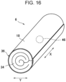
- Fig. 16 illustrates a perspective view of the filler element 6 formed to have the diameter reduced from the state illustrated in Fig. 15 .
- the opening 40 is closed. Accordingly, the capsule 46 does not extend off the folded part 36, and the filler element 6 in which the capsule 46 is placed inside the folded part 36 can be easily and reliably formed.
- the linear recess 44 is filled with the sheet 34, and the sheet 34 is brought into close contact with a circumference of the capsule 46.
- the capsule 46 is reliably fixed at a predetermined position in the axial direction X in the center of the folded part 36 in the radial direction Y Furthermore, a component of the addition agent released from the capsule 46 can be uniformly volatilized and dispersed in the radial direction Y from the center of the filler element 6 in the radial direction Y Accordingly, the quality of the filler element 6, and further, the inhaler 1 can be ensured.
- the capsule 46 is fixed and in close contact with the sheet 34 in the center of the folded part 36 in the radial direction Y, an operation performed when a user crushes the capsule 46 with the fingers to release the addition agent becomes easy, and accordingly, convenience of the user is improved.
- the above-described addition agent included in the additive 42 subjected to sorption to the linear recess 44, the above-described addition agent with which the thread is impregnated, and the above-described addition agent encapsulated in the capsule 46 are, for example, a flavor agent such as menthol, and further, may include, for example, active carbon or an aerosol extender.
- a substantially spherical conductive member may be used instead of the capsule 46.
- One or a plurality of conductive members are placed in the filler element 6.
- the filler element 6 using the sheet 34 formed of the nonwoven fabric containing ground tobacco or the extract of tobacco has the function of the flavor element 2.
- the conductive member is heated by the induced current when the magnetic field is generated by the device, and the heated conductive member heats the filler element 6 so as to volatilize and disperse the flavor component derived from the tobacco plant included in the filler element 6.
- Fig. 17 generally illustrates a manufacturing device 50 for manufacturing the filler element 6.
- Fig. 18 illustrates a flowchart explaining a manufacturing method for manufacturing the filler element 6.
- the manufacturing device 50 includes a sheet supplying section 52, a sheet processing section 54, a folding section 56, a wrapping section 58, a cutting section 60, and the like.
- the sheet supplying section 52 supplies the single continuous sheet 34 formed of the nonwoven fabric to a transport path 62 (S1: sheet supplying step).
- the sheet processing section 54 processes the sheet 34 while transporting the sheet 34 through the transport path 62 (S2: sheet processing step).
- the sheet processing section 54 includes a first roller set 64, a second roller set 66, a third roller set 68, and a control unit 70.
- Each of the roller sets 64, 66, and 68 includes a corresponding one of pairs of rollers Ra and Rb and is configured to transport the sheet 34 while pinching the sheet 34 in the transport path 62 with the pair of rollers Ra and Rb.
- a rotation shaft of at least one of the pair of the rollers Ra and Rb included in each of the roller sets 64, 66, and 68 is connected to a drive shaft of a corresponding one of motors (not illustrated) and separately rotated by the motor.
- the motors are electrically connected to the control unit 70.
- the rotation speed of each of the roller sets 64, 66, and 68 is controlled through the motor by using a signal from the control unit 70.
- the control unit 70 is configured to adjust the difference in rotation speed between the roller sets 64, 66, and 68, thereby to adjust the difference in transportation speed of the sheet 34 between the roller sets 64, 66, and 68.
- the drawing process illustrated in Fig. 8 is performed on the sheet 34 (P1: drawing processing).
- the rotation speed of the roller set on the downstream side in the transport path 62 (for example, the second roller set 66 or the third roller set 68) is set to be greater than the rotation speed of the roller set on the upstream side in the transport path 62 (the first roller set 64).
- the transportation speed of the sheet 34 at the roller set on the downstream side becomes greater than the transportation speed of the sheet 34 at the roller set on the upstream side, and the sheet 34 is drawn in the longitudinal direction X between the roller set on the upstream side and the roller set on the downstream side.
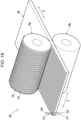
- Fig. 19 illustrates a perspective view of the first roller set 64 pinching the sheet 34.
- Many linear protrusions 72 are formed in the roller Ra so as to protrude throughout the circumference of an outer circumferential surface of the roller Ra.
- the compressed regions A1 are formed in the sheet 34 by using the linear protrusions 72.
- Many linear grooves 74 are formed in the outer circumferential surface of the roller Ra along with the formation of the linear protrusions 72.
- Non-compressed regions A2 are formed in the sheet 34 by using the linear grooves 74.
- Fig. 20 illustrates an enlarged view of part of the cross section of the roller Ra illustrated in Fig. 19 .
- Compressing surfaces 76 are formed at protruding ends of the linear protrusions 72.
- the compressing surfaces 76 have a width D3 in the width direction Z of the roller Ra (coincident with an axial direction of the roller Ra).
- Bottom surfaces 78 are formed in the linear grooves 74.
- the linear grooves 74 have a width D4 in the width direction Z.
- the width D3 of the compressing surfaces 76 is equal to the width D1 of the compressed regions A1 of the sheet 34 illustrated in Fig. 10 .
- the width D4 of the linear grooves 74 of the roller Ra is equal to the width D2 of the non-compressed regions A2 of the sheet 34 illustrated in Fig. 10 .
- Figs. 21 to 23 illustrate examples of combinations of the rollers Ra and Rb included in each of the roller sets 64, 66, and 68.
- Fig. 21 illustrates a cross-sectional view of the first roller set 64.
- Fig. 19 in this first roller set 64, many linear protrusions 72 are formed throughout the width direction Z of the roller Ra throughout the circumference of the outer circumferential surface of the roller Ra.
- Fig. 22 illustrates a cross-sectional view of the second roller set 66.
- the linear protrusions 72 having a greater width than that in the case of Fig. 21 are formed at both ends of the roller Ra in the width direction Z throughout the circumference of the outer circumferential surface of the roller Ra.
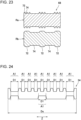
- Fig. 23 illustrates a cross-sectional view of the third roller set 68.
- this third roller set 68 three linear protrusions 72 having a width the same as or similar to that in the case of Fig. 21 are formed at three positions in the center and at both the ends of the roller Ra in the width direction Z throughout the circumference of the outer circumferential surface of the roller Ra.
- a single linear protrusion 72 having a width the same as or similar to that in the case of Fig. 22 is formed at each of three positions, that is, the center and both the ends of the roller Rb in the width direction Z throughout the circumference of the outer circumferential surface of the roller Rb.
- the linear protrusions 72 protruding throughout the circumference of the outer circumferential surface of the roller are formed in at least one roller out of the pair of rollers Ra and Rb included in each of the roller sets 64, 66, and 68 so as to allow the roller sets 64, 66, and 68 to grip and transport the sheet 34.
- Each of the linear protrusions 72 performs the compression process in which at least part of the sheet 34 in the width direction Z is compressed, and thereby the above-described compression processing is performed.
- Fig. 24 illustrates the end surface of the sheet 34 having passed through the roller sets 64, 66, and 68 illustrated in Figs. 21 to 23 .
- the percentage of the total compressed width Dt1 with respect to the sheet width Ds is adjusted to the predetermined percentage.
- the predetermined percentage is smaller than or equal to 50%.
- the compressed regionAl is formed in the center of the rear surface of the sheet 34 in the width direction Z due to the compression with the linear protrusion 72 of the roller Rb of the third roller set 68.
- the compressed region A1 is formed in the center of the front surface of the sheet 34 in the width direction Z by using the linear protrusion 72 of the roller Ra of the first roller set 64 and the linear protrusion 72 of the roller Ra of the third roller set 68.
- the width D1 of compressed regions A1 formed by the linear protrusion 72 of the roller Rb of the third roller set 68 is greater than the width D1 of the compressed region A1 formed by the linear protrusion 72 of the roller Ra of the first roller set 64 and the linear protrusion 72 of the roller Ra of the third roller set 68.
- the width D1 of the compressed region A1 formed by the linear protrusion 72 of the roller Rb of the third roller set 68 is added in calculating the total compressed width Dt1, but the width D1 of the compressed regionAl formed by the linear protrusions 72 of the roller Ra of the first roller set 64 and the roller Ra of the third roller set 68 is not added in calculating the total compressed width Dt1. That is, in the width direction Z, when the compressed regions A1 formed by the roller sets 64, 66, and 68 overlap, the width D1 of the larger compressed region A1 representing the widths D1 and is added in calculating the total compressed width Dt1.
- the percentage of the total compressed width Dt1 with respect to the sheet width Ds can be set to be the desired predetermined percentage by adjusting, in advance, the area of the compressing surfaces 76, the number, a formation range, and the like of the linear protrusions 72 formed in each of the roller sets 64, 66, and 68. Specifically, in each of the roller sets 64, 66, and 68, with consideration of the formation range of the linear protrusions 72 overlapping in the width direction Z of the sheet 34, the area of the compressing surfaces 76, the number, the formation range, and the like of the linear protrusions 72 contributing to the total compressed width Dt1 of the sheet 34 are adjusted.
- a gripping force of the linear protrusions 72 exerted on the sheet 34 can be adjusted by varying the gap between the pair of rollers Ra and Rb, the protruding height of the linear protrusions 72, the area of the compressing surfaces 76 of the linear protrusions 72, the number of the linear protrusions 72, and the like.
- the gripping force of the linear protrusions 72 exerted on the sheet 34 is optimized, accuracy of the drawing processing is improved.
- the folding section 56 folds, in the width direction Z, the sheet 34 having been processed in the sheet processing section 54 to form the folded rod 90 such that the folded rod 90 has the diameter reduced to a value smaller than or equal to the diameter of the filler element 6 (S3: folding step).
- the folded rod 90 becomes the folded part 36 when a filler rod 98 to be formed in a later step is cut into the filler element 6.
- the folding section 56 forms the opening 40 open in the axial direction X of the folded rod 90 at part of the folded rod 90 in the circumferential direction. Furthermore, the folding section 56 forms the linear recess 44 having a U-shaped section. The linear recess 44 is continuous with the opening 40 and recessed to the center of the folded rod 90 in the radial direction Y. Specifically, the folding section 56 includes, in order from the upstream side of the transport path 62, a preliminary folding guide 80, a transport jet 82, a trumpet guide 84, a tongue 86, and the like.
- Fig. 25 illustrates a front view of the preliminary folding guide 80.
- the preliminary folding guide 80 includes a guide roller 80a and a rotation shaft 80b by which the guide roller 80a is rotatably supported.
- the guide roller 80a is brought into contact with the center of the sheet 34, from below, in the width direction Z.
- the sheet 34 is curved so as to have an upwardly convex shape in the thickness direction of the sheet 34.
- Fig. 26 illustrates a cross-sectional view of the transport jet 82.
- Fig. 27 illustrates an end surface of the transport jet 82 on the upstream side in the transport path 62.
- the transport jet 82 has a cylindrical shape and has a large diameter portion 82a on the upstream side of the transport path 62 and a small diameter portion 82b continuous with the large diameter portion 82a.
- the diameter of an inner circumferential surface 82c of the transport jet 82 reduces from the large diameter portion 82a to the small diameter portion 82b so as to have a stepped shape.
- a baffle plate 88 stands erect on the inner circumferential surface 82c toward the center in the radial direction inside the transport jet 82.
- the transport jet 82 folds this sheet 34 a predetermined number of times in the width direction Z with the baffle plate 88 interposed between portions of the sheet 34 while pulling the sheet 34 thereinto by using air with a wind pressure.
- the transport jet 82 reduces the diameter of the sheet 34 while transporting the sheet 34 from the large diameter portion 82a to the small diameter portion 82b. In this way, the folded rod 90 is formed.
- Fig. 28 illustrates a cross-sectional view of the trumpet guide 84.
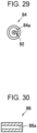
- Fig. 29 illustrates an end surface of the trumpet guide 84 on the upstream side in the transport path 62.
- the trumpet guide 84 has a cylindrical shape and has an inner circumferential surface 84a the diameter of which gradually reduces from the upstream side of the transport path 62.
- a baffle plate 92 stands erect on the inner circumferential surface 84a toward the center in the radial direction inside the trumpet guide 84.
- the baffle plates 88 and 92 respectively extend in the axial directions X of the transport jet 82 and the trumpet guide 84 inside the transport jet 82 and the trumpet guide 84.
- the folded rod 90 having passed through the transport jet 82 is released together with the air with the wind pressure, and the fabric of the folded rod 90 is loosened and opened by dissipation of the air due to the release. Furthermore, the folded rod 90 having formed in the transport jet 82 passes through the trumpet guide 84 with the baffle plate 92 interposed between portions thereof. Thus, a folded state of the folded rod 90 formed in the transport jet 82 is also maintained in the trumpet guide 84.
- the baffle plates 88 and 92 respectively stand erect on the inner circumferential surfaces 82c and 84a toward the centers in the radial directions in the transport jet 82 and the trumpet guide 84.
- the curved sheet 34 passing through the preliminary folding guide 80 is subjected to the air with the wind pressure and folded with the baffle plates 88 and 92 interposed between portions of the sheet 34, and thereby the sheet 34 is formed into the folded rod 90.
- the above-described opening 40 and the linear recess 44 are formed in part of the folded rod 90 in the circumferential direction.
- Fig. 30 illustrates a cross-sectional view of the tongue 86.
- the tongue 86 has a cylindrical shape and has an inner circumferential surface 86a the diameter of which is smaller than or equal to the diameter of the filler element 6.
- the diameter is reduced to a value smaller than or equal to the diameter of the filler element 6, the opening 40 is closed, and the linear recess 44 is filled with the sheet 34 in the tongue 86.
- the folding section 56 includes an additive supplying unit 94.
- the additive supplying unit 94 includes a nozzle 94a for supplying the additive 42.
- the nozzle 94a is inserted into both the transport jet 82 and the trumpet guide 84.
- the additive supplying unit 94 supplies the additive 42 into the folded rod 90 from the nozzle 94a through the opening 40 (P3: additive supplying processing).
- the additive supplying unit 94 supplies the additive 42 in the axial direction X of the linear recess 44 through the opening 40.
- the folding section 56 includes a capsule supplying unit 96.
- the capsule supplying unit 96 includes a rotation holder 96a having a circular pillar shape.
- the capsule 46 is held by the rotation holder 96a.
- the capsule supplying unit 96 supplies the capsule 46 held by the rotation holder 96a by intermittently dropping the capsule 46 into the folded rod 90 through the opening 40 while rotating the rotation holder 96a (P4: capsule supplying processing).
- the capsule supplying unit 96 supplies the capsule 46 to a predetermined position in the axial direction X of the linear recess 44 through the opening 40, for example, to a central position in the axial direction X when the folded rod 90 becomes the folded part 36.
- the wrapping section 58 supplies the wrapping paper 18 and wraps the folded rod 90 having been formed in the folding section 56 with the wrapping paper 18 so as to form the filler rod 98 (S4: wrapping step).
- the cutting section 60 cuts, into the filler element 6, the filler rod 98 having been formed in the wrapping section 58 (S5: cutting step), and the manufacturing of the filler element 6 ends.
- the filler element 6 includes the folded part 36 and the wrapping paper 18 wrapped around the folded part 36.
- the folded part 36 is formed by folding the single sheet 34 formed of the nonwoven fabric in the width direction Z such that the diameter is reduced to a value smaller than or equal to the diameter of the filler element 6.
- the drawing process in the longitudinal direction X is performed on the sheet 34 included in the folded part 36.
- the degree of drawing of the sheet 34 is adjusted, the folded part 36, and further, the filler element 6 having a plurality of filling densities can be formed by using the single sheet 34 of a single type. Furthermore, when only the drawing process is performed on the sheet 34, the parameter for controlling the filling density of the filler element 6 is only the setting of the degree of drawing performed on the single sheet 34. Accordingly, the filling density of the filler element 6 can be easily and highly accurately controlled. Furthermore, when the filling density of the filler element 6 is optimized, generation of gaps or cavities in the filler element 6 can be prevented. Thus, the quality of the inhaler 1 can be ensured.
- the sheet processing section 54 included in the manufacturing device 50 includes the roller sets 64, 66, and 68 and the control unit 70.
- the control unit 70 performs the drawing process in which the sheet 34 is drawn in the longitudinal direction X by adjusting the difference in transportation speed of the sheet 34 between the roller sets 64, 66, and 68.
- the drawing process is performed as the drawing processing in the transport process of the sheet 34.
- the degree of drawing of the sheet 34 can be easily adjusted. Accordingly, the filling density of the filler element 6 can be easily and highly accurately controlled.
- the folding section 56 included in the manufacturing device 50 includes the preliminary folding guide 80, the transport jet 82, the trumpet guide 84, and the tongue 86.
- the desired folded rod 90, and further, the desired filler element 6 can be reliably formed.
- the baffle plates 88 and 92 respectively stand erect on the inner circumferential surfaces 82c and 84a toward the centers in the radial directions in the transport jet 82 and the trumpet guide 84.
- the curved sheet 34 passing through the transport jet 82 and the trumpet guide 84 is folded, by using the air with the wind pressure, with the baffle plates 88 and 92 interposed between portions of the sheet 34, and thereby the sheet 34 is formed into the folded rod 90.
- the baffle plates 88 and 92 function as portions that start the folding of the sheet 34 and maintain the folded state of the sheet 34 during the folding of the sheet 34. Accordingly, when the baffle plates 88 and 92 are provided, the desired folded rod 90, and further, the desired filler element 6 can be more reliably formed.
- the above-described embodiment is not limiting and can be changed in various manners without departing from the gist.
- the number, the shape, or the formation range of the linear protrusions 72 is not limited to that in the described forms and can be changed in various manners.
- the linear protrusions 72 may be formed in both the rollers Ra and Rb or only in the roller Ra or the roller Rb.
- the roller sets be provided in the sheet processing section 54 for performing the drawing processing.
- the number of the roller sets is not limited to the above-described three sets including the roller sets 64, 66, and 68.
- the percentage of the total compressed width Dt1 with respect to the sheet width Ds is preferably smaller than or equal to 50%. However, this percentage can exceed 50% in accordance with the specifications of the sheet 34 or the required specifications of the filler element 6.
- both the drawing process and the compression process be necessarily performed on the sheet 34. Only one of the drawing process and the compression process may be performed on the sheet 34 in accordance with the specifications of the sheet 34 or the required specifications of the filler element 6. In accordance with the specifications of the sheet 34 or the required specifications of the filler element 6, there can be a case where neither the drawing process nor the compression process is performed.
- both the additive 42 and the capsule 46 be necessarily placed in the folded part 36.
- only one of the additive 42 and the capsule 46 may be placed.
- the configuration of the folding section 56 is not limited to the above-described configuration as long as the folded rod 90 can be formed.
- the configuration of the additive supplying unit 94 is not limited to the above-described configuration as long as the additive supplying processing can be performed.
- the configuration of the capsule supplying unit 96 is not limited to the above-described configuration as long as the capsule supplying processing can be performed.
- the configuration of the inhaler 1, the position of the filler element 6 in the inhaler 1, or the number of filler elements 6 in the inhaler 1 is not limited to that of the described forms.
Landscapes
- Chemical & Material Sciences (AREA)
- Engineering & Computer Science (AREA)
- Materials Engineering (AREA)
- Containers And Plastic Fillers For Packaging (AREA)
- Absorbent Articles And Supports Therefor (AREA)
Abstract
Description
- The present invention relates to a filler element, a filler element manufacturing method, and a filler element manufacturing device.
- A manufacturing method for manufacturing a filter element used in a cigarette is disclosed in
PTL 1. This filter element is formed by causing two or more sheets having a filtering function as a filter material to overlap each other while being shifted from each other by a certain width, folding the overlapping sheets into an S shape or a Z shape, and then, drawing and wrapping the sheets into a circular pillar shape. - PTL 1:
Japanese Examined Patent Application Publication No. 44-3727 - In addition to burning heating-type flavor inhalers including the cigarette described in
PTL 1, the filter element can be used in a non-burning heating-type flavor inhaler. A filling density of the filter material filled into the filter element exerts a significant influence on an airflow resistance generated when a user inhales a flavor inhaler, and further, on a smoke taste that can be obtained by the user. When the filling density of the filter element reduces, gaps or cavities are generated in the filter element. This significantly impairs the smoke taste and the appearance of the flavor inhaler. That is, the filling density of the filter element is an important factor for ensuring the quality of the flavor inhaler. - According to the manufacturing method described in
PTL 1, when the specifications of the flavor inhaler and the filter element used in the flavor inhaler are changed, the following operation is required to adjust the filling density of the filter element: preparing a plurality of sheets and varying the number of the sheets; adjusting a shifting width of the overlapping sheets, or changing the specifications of the sheet itself. - As described above, with the related art, there are various parameters for controlling the filling density of the filter element formed by filling the sheet, in other words, a filler element used in the flavor inhaler. Thus, it is difficult to easily and highly accurately control the filling density of the filler element in accordance with the required specifications.
- The present invention is made in view of such a problem, and an object of the present invention is to provide a filler element, a filler element manufacturing device, and a filler element manufacturing method with which the filling density can be easily and highly accurately controlled.
- In order to achieve the above-described object, a filler element according to an aspect is used in a flavor inhaler and includes a folded part formed by folding a single sheet formed of a nonwoven fabric in a width direction intersecting a longitudinal direction of the sheet such that the folded part has a diameter reduced to a value smaller than or equal to a diameter of the filler element and wrapping paper wrapped around the folded part. A drawing process is performed on the sheet in the longitudinal direction.
- A filler element manufacturing device according to an aspect is a manufacturing device for manufacturing a filler element used in a flavor inhaler. The filler element manufacturing device includes a sheet processing section configured to process a single sheet formed of a nonwoven fabric while transporting the sheet through a transport path, a folding section configured to fold, in a transport process of the sheet through the transport path, the sheet in a width direction intersecting a longitudinal direction of the sheet, the sheet having been processed in the sheet processing section, thereby to form a folded rod such that the folded rod has a diameter reduced to a value smaller than or equal to a diameter of the filler element, a wrapping section configured to wrap, with wrapping paper, the folded rod having been formed in the folding section, thereby to form a filler rod, and a cutting section configured to cut, into the filler element, the filler rod having been formed in the wrapping section. The sheet processing section includes a plurality of roller sets, the roller sets each including a pair of rollers and each configured to pinch and transport the sheet through the transport path with the pair of rollers, and a control unit configured to perform a drawing process in which the sheet is drawn in the longitudinal direction by adjusting a difference in transport speed of the sheet between the roller sets.
- A filler element manufacturing method according to an aspect is a manufacturing method for manufacturing a filler element used in a flavor inhaler. The filler element manufacturing method includes the steps of processing a single sheet formed of a nonwoven fabric while transporting the sheet, folding, in a transport process of the sheet, the sheet in a width direction intersecting a longitudinal direction of the sheet, the sheet having been processed in the processing of the sheet, thereby to form a folded rod such that the folded rod has a diameter reduced to a value smaller than or equal to a diameter of the filler element, wrapping, with wrapping paper, the folded rod having been formed in the folding, thereby to form a filler rod, and cutting, into the filler element, the filler rod having been formed in the wrapping. In the processing of the sheet, drawing processing in which the sheet is drawn in the longitudinal direction is performed in the transport process of the sheet. Advantageous Effects of Invention
- The filling density of the filler element can be easily and highly accurately controlled.
-
- [
Fig. 1] Fig. 1 is a cross-sectional view of a non-burning heating-type flavor inhaler - [
Fig. 2] Fig. 2 is a cross-sectional view of a non-burning heating-type flavor inhaler according to a variant. - [
Fig. 3] Fig. 3 is a cross-sectional view of a burning heating-type flavor inhaler. - [
Fig. 4] Fig. 4 is a cross-sectional view of a burning heating-type flavor inhaler according to a variant. - [
Fig. 5] Fig. 5 is a cross-sectional view of a burning heating-type flavor inhaler according to another variant. - [
Fig. 6] Fig. 6 illustrates an end surface of a filler element. - [
Fig. 7] Fig. 7 is a perspective view of a sheet on which a process has not been performed. - [
Fig. 8] Fig. 8 is a perspective view of the sheet on which a drawing process has been performed. - [
Fig. 9] Fig. 9 is a perspective view of the sheet on which a compression process has been performed. - [
Fig. 10] Fig. 10 is an enlarged view of part of an end surface of the sheet illustrated inFig. 9 . - [
Fig. 11] Fig. 11 is a perspective view of a folded part. - [
Fig.12] Fig.12 is a perspective view of the filler element formed to have a diameter reduced from a state illustrated inFig. 11 . - [
Fig. 13] Fig. 13 is a perspective view of the folded part in which an additive is placed. - [
Fig.14] Fig.14 is a perspective view of the filler element formed to have the diameter reduced from a state illustrated inFig. 13 . - [
Fig. 15] Fig. 15 is a perspective view of the folded part in which a capsule is placed. - [
Fig.16] Fig.16 is a perspective view of the filler element formed to have the diameter reduced from a state illustrated inFig. 15 . - [
Fig. 17] Fig. 17 generally illustrates a manufacturing device for manufacturing the filler element. - [
Fig. 18] Fig. 18 is a flowchart explaining a manufacturing method for manufacturing the filler element. - [
Fig. 19] Fig. 19 is a perspective view of a first roller set pinching a sheet. - [
Fig. 20] Fig. 20 is an enlarged view of part of the cross section of a roller illustrated inFig. 19 . - [
Fig. 21] Fig. 21 is a cross-sectional view of the first roller set. - [
Fig. 22] Fig. 22 is a cross-sectional view of a second roller set. - [
Fig. 23] Fig. 23 is a cross-sectional view of a third roller set. - [
Fig. 24] Fig. 24 illustrates an end surface of the sheet having passed through the roller sets illustrated inFigs. 21 to 23 . - [
Fig. 25] Fig. 25 is a front view of a preliminary folding guide. - [
Fig. 26] Fig. 26 is a cross-sectional view of a transport jet. - [
Fig. 27] Fig. 27 illustrates an end surface of the transport jet. - [
Fig. 28] Fig. 28 is a cross-sectional view of a trumpet guide. - [
Fig. 29] Fig. 29 illustrates an end surface of the trumpet guide. - [
Fig. 30] Fig. 30 is a cross-sectional view of a tongue. -
Fig. 1 illustrates a cross-sectional view of a non-burning heating-type flavor inhaler 1 (hereinafter, also referred to as an inhaler). Theinhaler 1 includes aflavor element 2, atubular element 4, and afiller element 6 in order from the left side (a distal end side of the inhaler 1) of the page ofFig. 1 . Theflavor element 2 is formed by filling aflavor material 8. - The device (flavor inhaler) used to heat the
flavor element 2 includes aheater 10 having, for example, a needle shape. Only theheater 10 of the device is illustrated inFig. 1 . Heating is performed by setting theinhaler 1 in the device and inserting theflavor element 2 into theheater 10. Thus, a flavor component of theflavor material 8 is volatilized and dispersed. - A conductive member such as a metal plate or a metal particle may be mixed in the
flavor material 8 filled in theflavor element 2. The conductive member is heated by an induced current when a magnetic field is generated by the device, and the heated conductive member heats theflavor element 2 so as to volatilize and disperse the flavor component of theflavor material 8. - The
flavor material 8 is, for example, shredded tobacco, a cut cigarette sheet, or a cigarette sheet folded into a gathered shape. Theflavor material 8 may be a sheet which is formed from pulp not containing tobacco and to which a flavor is added, a sheet which is formed of a non-tobacco plant and cut, or one of these sheets folded into a gathered shape. A circumferential surface of theflavor material 8 is wrapped with wrappingpaper 12. - The
tubular element 4 defines an airflow channel in theinhaler 1 and is formed from apaper tube 14 having, for example, a cylindrical shape. Thepaper tube 14 is formed of a single or double paper web. Thefiller element 6 is a filtering body filled with afiller material 16. Thefiller material 16 is formed by folding asingle sheet 34 made of a nonwoven fabric. A circumferential surface of thefiller element 6 is wrapped with wrappingpaper 18. - The
elements elements paper 20 is wrapped around a circumferential surface of the continuous body. Air holes 22 are formed in thetubular element 4 and the tippingpaper 20 to bring air into theinhaler 1 during inhalation using theinhaler 1. The flavor component of theflavor element 2 and a volatilized component of an addition agent, which will be described later, are cooled by the air brought into theinhaler 1 from outside through the air holes 22, and thereby, aerosolization of these components is promoted. -
Fig. 2 illustrates a cross-sectional view of a non-burning heating-type inhaler 1 according to a variant. Theinhaler 1 includes thefiller element 6 at a position the same as or similar to that illustrated inFig. 1 . Theinhaler 1 includes anotherfiller element 6 at a position adjacent to theflavor element 2 on the opposite side of theflavor element 2 from thetubular element 4, that is, at a distal end of theinhaler 1. Thefiller element 6 at the distal end is connected to theflavor element 2 with wrappingpaper 24. Theheater 10 penetrates thefiller element 6 at the distal end and is inserted into theflavor element 2. - In so doing, the
filler element 6 at the distal end suppresses spilling of theflavor material 8 from theflavor element 2 to a base portion of theheater 10. That is, in theinhaler 1, thefiller element 6 at the distal end functions as a supporting segment that supports so that theflavor material 8 filled in theflavor element 2 does not spill toward theheater 10. This suppresses contamination, with the spilledflavor material 8, of a portion at or around the base portion of theheater 10 of the device. -
Fig. 3 illustrates a cross-sectional view of a burningheating type inhaler 1. Theinhaler 1 includes theflavor element 2 and thefiller element 6 in order from the distal end side. When theflavor element 2 is ignited and heated, the flavor component of theflavor material 8 is volatilized.Fig. 4 illustrates a cross-sectional view of a burning heating-type inhaler 1 according to a variant. Theinhaler 1 includes theflavor element 2, afilter element 26, and thefiller element 6 in order from the distal end side. Thefilter element 26 is formed by wrappingpaper 30 around afilter material 28 different from thefiller material 16 of thefiller element 6, for example, acetate tow. Thefilter element 26 is connected to thefiller element 6 by usingwrapping paper 32. -
Fig. 5 illustrates a cross-sectional view of a burning heating-type inhaler 1 according to another variant. Thisinhaler 1 includes theflavor element 2, thefiller element 6, and thefilter element 26 in order from the distal end side. This is a pattern in which the arrangement of thefilter element 26 and thefiller element 6 is changed from that of theinhaler 1 illustrated inFig. 4 , and the other configurations are the same as or similar to those of theinhaler 1 illustrated inFig. 4 . -
Fig. 6 illustrates an end surface of thefiller element 6. Thefiller material 16 of thefiller element 6 is thesingle sheet 34 that is mainly formed of a dry-type nonwoven fabric formed by bonding pieces of plant pulp to each other with a watersoluble binder. The plant pulp may be wood pulp that is a non-tobacco plant. Thesheet 34 may be formed by adding a ground tobacco plant or an extract of a tobacco plant to the nonwoven fabric. - In this case, the flavor component derived from the tobacco plant can be volatilized and dispersed not only from the
flavor element 2 but also from thefiller element 6. That is, thefiller element 6 using thesheet 34 formed of the nonwoven fabric containing ground tobacco or the extract of tobacco has not only the function of a filtering element serving as a filtering body but also the function of theflavor element 2. - When this
sheet 34 is folded a predetermined number of times, for example, three or four times in the width direction Z such that the diameter is reduced, a foldedrod 90, which will be described later, is formed, and further, a foldedpart 36 is formed by cutting the foldedrod 90. The width direction Z is a direction intersecting a longitudinal direction X of the sheet 34 (coincident with the axial direction X). - The
filler element 6 is formed by wrapping a circumferential surface of the foldedpart 36 with the wrappingpaper 18, and both ends of the wrappingpaper 18 is wrapped by using glue. When the foldedpart 36, and further, thefiller element 6 are formed by folding thesingle sheet 34, unlike the related art, none of the following operations for adjusting a filling density of thefiller element 6 is required: preparing a plurality ofsheets 34 and varying the number of thesheets 34; adjusting a shifting width of the overlappingsheets 34; and changing the specifications of thesheet 34 itself. - Accordingly, compared to the related-art case, the filling density of the
filler element 6 can be easily and highly accurately controlled. Furthermore, for the foldedpart 36, the filling density of thesheet 34 as thefiller material 16 can be further optimized by performing a process described below on thesheet 34. Thus, generation of gaps or cavities in thefiller element 6 can be more effectively prevented. -
Fig. 7 illustrates a perspective view of thesheet 34 on which the process has not been performed. Since thesheet 34 is formed of a nonwoven fabric that has not been woven but intertwined, thesheet 34 has a substantially irreversible drawing property in the longitudinal direction X and has a risingparts 38 at front and rear surfaces thereof. Thesheet 34 has a thickness t including the risingparts 38. -
Fig. 8 illustrates a perspective view of thesheet 34 on which a drawing process has been performed. When the drawing process has been performed, the length of thesheet 34 increases in the longitudinal direction X and the thickness t of thesheet 34 reduces to t1 representing a smaller thickness than the thickness t. When the length of thesheet 34 increases in the longitudinal direction X and the surface area of thesheet 34 increases, the density of the rising parts 38 (rising density) on the front and rear surfaces of thesheet 34 reduces. When the degree of drawing of thesheet 34 is adjusted, the thickness and the rising density of the entirety of thesheet 34 can be controlled. Accordingly, the foldedpart 36, and further, thefiller element 6 having a plurality of filling densities can be formed by using thesingle sheet 34 of a single type. -
Fig. 9 illustrates a perspective view of thesheet 34 on which a compression process has been performed.Fig. 10 illustrates an enlarged view of part of an end surface of thesheet 34 illustrated inFig. 9 . The compression process in which at least parts of thesheet 34 in the width direction Z are compressed is performed on thesheet 34. In thesheet 34 illustrated inFig. 9 serving as an example of a compressed form, as illustrated inFig. 10 , many compressed regions A1 having a width D1 in the width direction Z and many non-compressed regions A2 having a width D2 in the width direction Z are formed in the longitudinal direction X. - The non-compressed regions A2 are regions other than the compressed regions A1 in the
sheet 34 and each of the non-compressed regions A2 has incompletely compressed inclined surfaces and a flat surface that has not been compressed at all. When the sum of widths D1 of the compressed regions A1 in the width direction Z where thesheet 34 is compressed is defined as a total compressed width Dt1 of thesheet 34, the percentage of the total compressed width Dt1 with respect to the width of thesheet 34 in the width direction Z, that is, a sheet width Ds is a predetermined percentage. This predetermined percentage is set to be smaller than or equal to 50%. - In the compressed regions A1 of the
sheet 34, the thickness t1 reduces to a smaller thickness t2 due to compression. When the risingparts 38 are crushed, the rising density in the compressed regions A1 of the front and rear surfaces of thesheet 34 reduces significantly. Meanwhile, the thickness t1 and the rising density after the drawing process has been performed are substantially maintained in the non-compressed regions A2 of the sheet. - When a formation range of the compressed regions A1 of the
sheet 34 is adjusted and the percentage of the total compressed width Dt1 with respect to the sheet width Ds is set to be the predetermined percentage, that is, the degree of compressing thesheet 34 is adjusted, the thickness and the rising density of the entirety of thesheet 34 can be controlled. Accordingly, the foldedpart 36, and further, thefiller element 6 having a plurality of filling densities can be easily formed by using thesingle sheet 34 of a single type. -
Fig. 11 illustrates a perspective view of the foldedpart 36.Fig. 12 illustrates a perspective view of thefiller element 6 formed to have the diameter reduced from the state illustrated inFig. 11 . As a result of folding thesheet 34, the foldedpart 36 has anopening 40 formed in the axial direction X at part of the foldedpart 36 in a circumferential direction. When the foldedpart 36 in which theopening 40 has been formed is wrapped with the wrappingpaper 18 after the diameter of the foldedpart 36 has been reduced, theopening 40 is closed and thefiller element 6 illustrated inFig. 12 is formed. - When the folded
part 36 is formed by folding thesingle sheet 34 as described above, unlike the related art, none of the following operations for adjusting the filling density of thefiller element 6 is required: preparing a plurality ofsheets 34 and varying the number of thesheets 34; adjusting the shifting width of the overlappingsheets 34; and changing the specifications of thesheet 34 itself. - Accordingly, the filling density of the
filler element 6 can be easily and highly accurately controlled. Furthermore, when the number of times of folding thesingle sheet 34, the form of folding, or the degree of reduction of the diameter of the foldedpart 36 is adjusted, the filling density of thefiller element 6 can be optimized. Accordingly, since generation of gaps or cavities in thefiller element 6 can be prevented, the quality of theinhaler 1 can be ensured. - Furthermore, when the drawing process and the compression process are performed on the
sheet 34, parameters for controlling the filling density of thefiller element 6 are only settings of the degrees of drawing and compressing performed on thesingle sheet 34. Thus, the filling density of thefiller element 6 can be more easily and highly accurately controlled. Furthermore, when the filling density of thefiller element 6 is further optimized by the drawing process and the compression process of thesheet 34, the generation of gaps or cavities in thefiller element 6 can be more effectively prevented, and accordingly, the reliability in ensuring the quality of theinhaler 1 is improved. - In particular, when the compression process is performed on the
sheet 34, the predetermined percentage of the total compressed width Dt1 with respect to the sheet width Ds is set to be smaller than or equal to 50%. In this way, the risingparts 38 can remain in thesheet 34 in a range more than 50% of the sheet width Ds. Accordingly, a significant reduction of the rising density of thesheet 34 is suppressed, and the generation of gaps or cavities in thefiller element 6 can be still more reliably prevented. -
Fig. 13 illustrates a perspective view of the foldedpart 36 in which an additive 42 is placed. The foldedpart 36 has theopening 40 open in the axial direction X of the foldedpart 36 at part in the circumferential direction of the foldedpart 36. The additive 42 is placed inside the foldedpart 36 through theopening 40. Thus, the additive 42 can be placed in an appropriate position in thefiller element 6 while the filling density of thefiller element 6 is optimized. - Furthermore, a
linear recess 44 having a U-shaped section is formed in the foldedpart 36. Thelinear recess 44 is continuous with theopening 40 and recessed to the center of the foldedpart 36 in a radial direction Y The additive 42 is placed in the axial direction X of thelinear recess 44 through theopening 40. Thus, the additive 42 can be reliably placed in the center of the foldedpart 36 in the radial direction Y -
Fig. 14 illustrates a perspective view of thefiller element 6 formed to have the diameter reduced from the state illustrated inFig. 13 . When the diameter of the foldedpart 36 is reduced, and the foldedpart 36 is wrapped with the wrappingpaper 18, theopening 40 is closed. Accordingly, the additive 42 does not extend off the foldedpart 36, and thefiller element 6 in which the additive 42 is placed inside the foldedpart 36 can be easily and reliably formed. Furthermore, when the diameter of the foldedpart 36 is reduced, thelinear recess 44 in which the additive 42 is placed is filled with thesheet 34. - Thus, the additive 42 is reliably positioned in the center of the folded
part 36 in the radial direction Y Furthermore, a component of the additive 42 can be uniformly volatilized and dispersed in the radial direction Y from the center of thefiller element 6 in the radial direction Y Accordingly, the reliability of ensuring the quality of thefiller element 6, and further, theinhaler 1 is improved. The additive 42 may be an addition agent including a liquid subjected to sorption to thelinear recess 44 or a thread placed in thelinear recess 44. When the thread is placed, the thread is impregnated with an addition agent including a liquid. - Furthermore, the additive 42 may be a conductive member having a thread shape or an elongated flat plate shape. The
filler element 6 using thesheet 34 formed of the nonwoven fabric containing ground tobacco or the extract of tobacco has the function of theflavor element 2. The conductive member is heated by the induced current when the magnetic field is generated by the device, and the heated conductive member heats thefiller element 6 so as to volatilize and disperse the flavor component derived from the tobacco plant included in thefiller element 6. -
Fig. 15 illustrates a perspective view of the foldedpart 36 in which acapsule 46 is placed. An outer shell of thecapsule 46 is formed of an easily destructive material, and the addition agent is encapsulated in the outer shell. When theopening 40 is formed in the foldedpart 36, thecapsule 46 can be placed at a predetermined position inside the foldedpart 36 through theopening 40. Thecapsule 46 is placed at, for example, a central position in the foldedpart 36 in the axial direction X. -
Fig. 16 illustrates a perspective view of thefiller element 6 formed to have the diameter reduced from the state illustrated inFig. 15 . When the diameter of the foldedpart 36 is reduced, and the foldedpart 36 is wrapped with the wrappingpaper 18, theopening 40 is closed. Accordingly, thecapsule 46 does not extend off the foldedpart 36, and thefiller element 6 in which thecapsule 46 is placed inside the foldedpart 36 can be easily and reliably formed. Furthermore, when the diameter of the foldedpart 36 is reduced, thelinear recess 44 is filled with thesheet 34, and thesheet 34 is brought into close contact with a circumference of thecapsule 46. - Thus, the
capsule 46 is reliably fixed at a predetermined position in the axial direction X in the center of the foldedpart 36 in the radial direction Y Furthermore, a component of the addition agent released from thecapsule 46 can be uniformly volatilized and dispersed in the radial direction Y from the center of thefiller element 6 in the radial direction Y Accordingly, the quality of thefiller element 6, and further, theinhaler 1 can be ensured. - Furthermore, since the
capsule 46 is fixed and in close contact with thesheet 34 in the center of the foldedpart 36 in the radial direction Y, an operation performed when a user crushes thecapsule 46 with the fingers to release the addition agent becomes easy, and accordingly, convenience of the user is improved. Furthermore, the above-described addition agent included in the additive 42 subjected to sorption to thelinear recess 44, the above-described addition agent with which the thread is impregnated, and the above-described addition agent encapsulated in thecapsule 46 are, for example, a flavor agent such as menthol, and further, may include, for example, active carbon or an aerosol extender. - Instead of the
capsule 46, a substantially spherical conductive member may be used. One or a plurality of conductive members are placed in thefiller element 6. Thefiller element 6 using thesheet 34 formed of the nonwoven fabric containing ground tobacco or the extract of tobacco has the function of theflavor element 2. The conductive member is heated by the induced current when the magnetic field is generated by the device, and the heated conductive member heats thefiller element 6 so as to volatilize and disperse the flavor component derived from the tobacco plant included in thefiller element 6. -
Fig. 17 generally illustrates amanufacturing device 50 for manufacturing thefiller element 6.Fig. 18 illustrates a flowchart explaining a manufacturing method for manufacturing thefiller element 6. Themanufacturing device 50 includes asheet supplying section 52, asheet processing section 54, afolding section 56, awrapping section 58, acutting section 60, and the like. - When manufacturing of the
filler element 6 is started, thesheet supplying section 52 supplies the singlecontinuous sheet 34 formed of the nonwoven fabric to a transport path 62 (S1: sheet supplying step). Next, thesheet processing section 54 processes thesheet 34 while transporting thesheet 34 through the transport path 62 (S2: sheet processing step). - The
sheet processing section 54 includes a first roller set 64, a second roller set 66, a third roller set 68, and acontrol unit 70. Each of the roller sets 64, 66, and 68 includes a corresponding one of pairs of rollers Ra and Rb and is configured to transport thesheet 34 while pinching thesheet 34 in thetransport path 62 with the pair of rollers Ra and Rb. - A rotation shaft of at least one of the pair of the rollers Ra and Rb included in each of the roller sets 64, 66, and 68 is connected to a drive shaft of a corresponding one of motors (not illustrated) and separately rotated by the motor. The motors are electrically connected to the
control unit 70. The rotation speed of each of the roller sets 64, 66, and 68 is controlled through the motor by using a signal from thecontrol unit 70. - The
control unit 70 is configured to adjust the difference in rotation speed between the roller sets 64, 66, and 68, thereby to adjust the difference in transportation speed of thesheet 34 between the roller sets 64, 66, and 68. Thus, in the sheet processing step, the drawing process illustrated inFig. 8 is performed on the sheet 34 (P1: drawing processing). - Specifically, the rotation speed of the roller set on the downstream side in the transport path 62 (for example, the second roller set 66 or the third roller set 68) is set to be greater than the rotation speed of the roller set on the upstream side in the transport path 62 (the first roller set 64). Thus, the transportation speed of the
sheet 34 at the roller set on the downstream side becomes greater than the transportation speed of thesheet 34 at the roller set on the upstream side, and thesheet 34 is drawn in the longitudinal direction X between the roller set on the upstream side and the roller set on the downstream side. -
Fig. 19 illustrates a perspective view of the first roller set 64 pinching thesheet 34. Manylinear protrusions 72 are formed in the roller Ra so as to protrude throughout the circumference of an outer circumferential surface of the roller Ra. The compressed regions A1 are formed in thesheet 34 by using thelinear protrusions 72. Manylinear grooves 74 are formed in the outer circumferential surface of the roller Ra along with the formation of thelinear protrusions 72. Non-compressed regions A2 are formed in thesheet 34 by using thelinear grooves 74. - In a transport process of the
sheet 34, when thelinear protrusions 72 are pushed into the surface of thesheet 34 so as to compress thesheet 34, in other words, grip thesheet 34, thesheet 34 is fed from the first roller set 64 toward the second roller set 66. Thus, in the sheet processing step, the compression process illustrated inFig. 9 is performed on the sheet 34 (P2: compression processing). -
Fig. 20 illustrates an enlarged view of part of the cross section of the roller Ra illustrated inFig. 19 . Compressing surfaces 76 are formed at protruding ends of thelinear protrusions 72. The compressing surfaces 76 have a width D3 in the width direction Z of the roller Ra (coincident with an axial direction of the roller Ra). Bottom surfaces 78 are formed in thelinear grooves 74. Thelinear grooves 74 have a width D4 in the width direction Z. The width D3 of the compressing surfaces 76 is equal to the width D1 of the compressed regions A1 of thesheet 34 illustrated inFig. 10 . The width D4 of thelinear grooves 74 of the roller Ra is equal to the width D2 of the non-compressed regions A2 of thesheet 34 illustrated inFig. 10 . -
Figs. 21 to 23 illustrate examples of combinations of the rollers Ra and Rb included in each of the roller sets 64, 66, and 68.Fig. 21 illustrates a cross-sectional view of the first roller set 64. As illustrated inFig. 19 , in this first roller set 64, manylinear protrusions 72 are formed throughout the width direction Z of the roller Ra throughout the circumference of the outer circumferential surface of the roller Ra.Fig. 22 illustrates a cross-sectional view of the second roller set 66. In this second roller set 66, thelinear protrusions 72 having a greater width than that in the case ofFig. 21 are formed at both ends of the roller Ra in the width direction Z throughout the circumference of the outer circumferential surface of the roller Ra. -
Fig. 23 illustrates a cross-sectional view of the third roller set 68. In this third roller set 68, threelinear protrusions 72 having a width the same as or similar to that in the case ofFig. 21 are formed at three positions in the center and at both the ends of the roller Ra in the width direction Z throughout the circumference of the outer circumferential surface of the roller Ra. Also in this third roller set 68, a singlelinear protrusion 72 having a width the same as or similar to that in the case ofFig. 22 is formed at each of three positions, that is, the center and both the ends of the roller Rb in the width direction Z throughout the circumference of the outer circumferential surface of the roller Rb. - As described above, the
linear protrusions 72 protruding throughout the circumference of the outer circumferential surface of the roller are formed in at least one roller out of the pair of rollers Ra and Rb included in each of the roller sets 64, 66, and 68 so as to allow the roller sets 64, 66, and 68 to grip and transport thesheet 34. Each of thelinear protrusions 72 performs the compression process in which at least part of thesheet 34 in the width direction Z is compressed, and thereby the above-described compression processing is performed. -
Fig. 24 illustrates the end surface of thesheet 34 having passed through the roller sets 64, 66, and 68 illustrated inFigs. 21 to 23 . When the sum of widths D1 of the compressed regions A1 where thesheet 34 is compressed with thelinear protrusions 72 in the width direction Z is defined as the total compressed width Dt1 of thesheet 34, the percentage of the total compressed width Dt1 with respect to the sheet width Ds is adjusted to the predetermined percentage. As has been described, the predetermined percentage is smaller than or equal to 50%. Here, as illustrated inFig. 24 , the compressed regionAl is formed in the center of the rear surface of thesheet 34 in the width direction Z due to the compression with thelinear protrusion 72 of the roller Rb of the third roller set 68. - Meanwhile, the compressed region A1 is formed in the center of the front surface of the
sheet 34 in the width direction Z by using thelinear protrusion 72 of the roller Ra of the first roller set 64 and thelinear protrusion 72 of the roller Ra of the third roller set 68. The width D1 of compressed regions A1 formed by thelinear protrusion 72 of the roller Rb of the third roller set 68 is greater than the width D1 of the compressed region A1 formed by thelinear protrusion 72 of the roller Ra of the first roller set 64 and thelinear protrusion 72 of the roller Ra of the third roller set 68. - In this case, in the case of
Fig. 24 , the width D1 of the compressed region A1 formed by thelinear protrusion 72 of the roller Rb of the third roller set 68 is added in calculating the total compressed width Dt1, but the width D1 of the compressed regionAl formed by thelinear protrusions 72 of the roller Ra of the first roller set 64 and the roller Ra of the third roller set 68 is not added in calculating the total compressed width Dt1. That is, in the width direction Z, when the compressed regions A1 formed by the roller sets 64, 66, and 68 overlap, the width D1 of the larger compressed region A1 representing the widths D1 and is added in calculating the total compressed width Dt1. - The percentage of the total compressed width Dt1 with respect to the sheet width Ds can be set to be the desired predetermined percentage by adjusting, in advance, the area of the compressing surfaces 76, the number, a formation range, and the like of the
linear protrusions 72 formed in each of the roller sets 64, 66, and 68. Specifically, in each of the roller sets 64, 66, and 68, with consideration of the formation range of thelinear protrusions 72 overlapping in the width direction Z of thesheet 34, the area of the compressing surfaces 76, the number, the formation range, and the like of thelinear protrusions 72 contributing to the total compressed width Dt1 of thesheet 34 are adjusted. - In this way, the percentage of the total compressed width Dt1 with respect to the sheet width Ds can be adjusted. Furthermore, a gripping force of the
linear protrusions 72 exerted on thesheet 34 can be adjusted by varying the gap between the pair of rollers Ra and Rb, the protruding height of thelinear protrusions 72, the area of the compressing surfaces 76 of thelinear protrusions 72, the number of thelinear protrusions 72, and the like. When the gripping force of thelinear protrusions 72 exerted on thesheet 34 is optimized, accuracy of the drawing processing is improved. - Next, in the transport process of the
sheet 34 through thetransport path 62, thefolding section 56 folds, in the width direction Z, thesheet 34 having been processed in thesheet processing section 54 to form the foldedrod 90 such that the foldedrod 90 has the diameter reduced to a value smaller than or equal to the diameter of the filler element 6 (S3: folding step). The foldedrod 90 becomes the foldedpart 36 when afiller rod 98 to be formed in a later step is cut into thefiller element 6. - Furthermore, in the process of folding the
sheet 34, thefolding section 56 forms theopening 40 open in the axial direction X of the foldedrod 90 at part of the foldedrod 90 in the circumferential direction. Furthermore, thefolding section 56 forms thelinear recess 44 having a U-shaped section. Thelinear recess 44 is continuous with theopening 40 and recessed to the center of the foldedrod 90 in the radial direction Y. Specifically, thefolding section 56 includes, in order from the upstream side of thetransport path 62, apreliminary folding guide 80, atransport jet 82, atrumpet guide 84, atongue 86, and the like. -
Fig. 25 illustrates a front view of thepreliminary folding guide 80. Thepreliminary folding guide 80 includes aguide roller 80a and arotation shaft 80b by which theguide roller 80a is rotatably supported. In the transport process of thesheet 34 through thetransport path 62, theguide roller 80a is brought into contact with the center of thesheet 34, from below, in the width direction Z. Thus, thesheet 34 is curved so as to have an upwardly convex shape in the thickness direction of thesheet 34. -
Fig. 26 illustrates a cross-sectional view of thetransport jet 82.Fig. 27 illustrates an end surface of thetransport jet 82 on the upstream side in thetransport path 62. Thetransport jet 82 has a cylindrical shape and has alarge diameter portion 82a on the upstream side of thetransport path 62 and asmall diameter portion 82b continuous with thelarge diameter portion 82a. The diameter of an innercircumferential surface 82c of thetransport jet 82 reduces from thelarge diameter portion 82a to thesmall diameter portion 82b so as to have a stepped shape. - A
baffle plate 88 stands erect on the innercircumferential surface 82c toward the center in the radial direction inside thetransport jet 82. Regarding thesheet 34 that has passed through thepreliminary folding guide 80 and has been curved, thetransport jet 82 folds this sheet 34 a predetermined number of times in the width direction Z with thebaffle plate 88 interposed between portions of thesheet 34 while pulling thesheet 34 thereinto by using air with a wind pressure. In addition, thetransport jet 82 reduces the diameter of thesheet 34 while transporting thesheet 34 from thelarge diameter portion 82a to thesmall diameter portion 82b. In this way, the foldedrod 90 is formed. -
Fig. 28 illustrates a cross-sectional view of thetrumpet guide 84.Fig. 29 illustrates an end surface of thetrumpet guide 84 on the upstream side in thetransport path 62. Thetrumpet guide 84 has a cylindrical shape and has an innercircumferential surface 84a the diameter of which gradually reduces from the upstream side of thetransport path 62. Furthermore, abaffle plate 92 stands erect on the innercircumferential surface 84a toward the center in the radial direction inside thetrumpet guide 84. Thebaffle plates transport jet 82 and thetrumpet guide 84 inside thetransport jet 82 and thetrumpet guide 84. - In the
trumpet guide 84, the foldedrod 90 having passed through thetransport jet 82 is released together with the air with the wind pressure, and the fabric of the foldedrod 90 is loosened and opened by dissipation of the air due to the release. Furthermore, the foldedrod 90 having formed in thetransport jet 82 passes through thetrumpet guide 84 with thebaffle plate 92 interposed between portions thereof. Thus, a folded state of the foldedrod 90 formed in thetransport jet 82 is also maintained in thetrumpet guide 84. - As described above, the
baffle plates circumferential surfaces transport jet 82 and thetrumpet guide 84. Thecurved sheet 34 passing through thepreliminary folding guide 80 is subjected to the air with the wind pressure and folded with thebaffle plates sheet 34, and thereby thesheet 34 is formed into the foldedrod 90. When thesheet 34 is folded with thebaffle plates sheet 34, the above-describedopening 40 and thelinear recess 44 are formed in part of the foldedrod 90 in the circumferential direction. -
Fig. 30 illustrates a cross-sectional view of thetongue 86. Thetongue 86 has a cylindrical shape and has an innercircumferential surface 86a the diameter of which is smaller than or equal to the diameter of thefiller element 6. Regarding the foldedrod 90 having passed through thetrumpet guide 84, the diameter is reduced to a value smaller than or equal to the diameter of thefiller element 6, theopening 40 is closed, and thelinear recess 44 is filled with thesheet 34 in thetongue 86. - As illustrated in
Fig. 17 , thefolding section 56 includes an additive supplyingunit 94. The additive supplyingunit 94 includes anozzle 94a for supplying the additive 42. Thenozzle 94a is inserted into both thetransport jet 82 and thetrumpet guide 84. At least before the foldedrod 90 is transported to thetongue 86, theadditive supplying unit 94 supplies the additive 42 into the foldedrod 90 from thenozzle 94a through the opening 40 (P3: additive supplying processing). Specifically, theadditive supplying unit 94 supplies the additive 42 in the axial direction X of thelinear recess 44 through theopening 40. - Furthermore, the
folding section 56 includes acapsule supplying unit 96. Thecapsule supplying unit 96 includes arotation holder 96a having a circular pillar shape. Thecapsule 46 is held by therotation holder 96a. At least before the foldedrod 90 is transported to thetongue 86, thecapsule supplying unit 96 supplies thecapsule 46 held by therotation holder 96a by intermittently dropping thecapsule 46 into the foldedrod 90 through theopening 40 while rotating therotation holder 96a (P4: capsule supplying processing). Specifically, thecapsule supplying unit 96 supplies thecapsule 46 to a predetermined position in the axial direction X of thelinear recess 44 through theopening 40, for example, to a central position in the axial direction X when the foldedrod 90 becomes the foldedpart 36. - Next, as illustrated in
Fig. 17 , thewrapping section 58 supplies the wrappingpaper 18 and wraps the foldedrod 90 having been formed in thefolding section 56 with the wrappingpaper 18 so as to form the filler rod 98 (S4: wrapping step). Next, the cuttingsection 60 cuts, into thefiller element 6, thefiller rod 98 having been formed in the wrapping section 58 (S5: cutting step), and the manufacturing of thefiller element 6 ends. - As has been described, the
filler element 6 according to the embodiment includes the foldedpart 36 and thewrapping paper 18 wrapped around the foldedpart 36. The foldedpart 36 is formed by folding thesingle sheet 34 formed of the nonwoven fabric in the width direction Z such that the diameter is reduced to a value smaller than or equal to the diameter of thefiller element 6. The drawing process in the longitudinal direction X is performed on thesheet 34 included in the foldedpart 36. - When the degree of drawing of the
sheet 34 is adjusted, the foldedpart 36, and further, thefiller element 6 having a plurality of filling densities can be formed by using thesingle sheet 34 of a single type. Furthermore, when only the drawing process is performed on thesheet 34, the parameter for controlling the filling density of thefiller element 6 is only the setting of the degree of drawing performed on thesingle sheet 34. Accordingly, the filling density of thefiller element 6 can be easily and highly accurately controlled. Furthermore, when the filling density of thefiller element 6 is optimized, generation of gaps or cavities in thefiller element 6 can be prevented. Thus, the quality of theinhaler 1 can be ensured. - Furthermore, the
sheet processing section 54 included in themanufacturing device 50 according to the embodiment includes the roller sets 64, 66, and 68 and thecontrol unit 70. Thecontrol unit 70 performs the drawing process in which thesheet 34 is drawn in the longitudinal direction X by adjusting the difference in transportation speed of thesheet 34 between the roller sets 64, 66, and 68. In the sheet processing step, the drawing process is performed as the drawing processing in the transport process of thesheet 34. Thus, in the transport process of thesheet 34, the degree of drawing of thesheet 34 can be easily adjusted. Accordingly, the filling density of thefiller element 6 can be easily and highly accurately controlled. - Furthermore, the
folding section 56 included in themanufacturing device 50 according to the embodiment includes thepreliminary folding guide 80, thetransport jet 82, thetrumpet guide 84, and thetongue 86. In the transport process of thesheet 34, when thesheet 34 passes through these portions of thefolding section 56, the desired foldedrod 90, and further, the desiredfiller element 6 can be reliably formed. - More specifically, the
baffle plates circumferential surfaces transport jet 82 and thetrumpet guide 84. Thecurved sheet 34 passing through thetransport jet 82 and thetrumpet guide 84 is folded, by using the air with the wind pressure, with thebaffle plates sheet 34, and thereby thesheet 34 is formed into the foldedrod 90. - That is, the
baffle plates sheet 34 and maintain the folded state of thesheet 34 during the folding of thesheet 34. Accordingly, when thebaffle plates rod 90, and further, the desiredfiller element 6 can be more reliably formed. - Although the description of the embodiment is completed with the above description, the above-described embodiment is not limiting and can be changed in various manners without departing from the gist. For example, the number, the shape, or the formation range of the
linear protrusions 72 is not limited to that in the described forms and can be changed in various manners. Thelinear protrusions 72 may be formed in both the rollers Ra and Rb or only in the roller Ra or the roller Rb. - Furthermore, it is sufficient that at least a plurality of the roller sets be provided in the
sheet processing section 54 for performing the drawing processing. The number of the roller sets is not limited to the above-described three sets including the roller sets 64, 66, and 68. Furthermore, the percentage of the total compressed width Dt1 with respect to the sheet width Ds is preferably smaller than or equal to 50%. However, this percentage can exceed 50% in accordance with the specifications of thesheet 34 or the required specifications of thefiller element 6. - It is not required that both the drawing process and the compression process be necessarily performed on the
sheet 34. Only one of the drawing process and the compression process may be performed on thesheet 34 in accordance with the specifications of thesheet 34 or the required specifications of thefiller element 6. In accordance with the specifications of thesheet 34 or the required specifications of thefiller element 6, there can be a case where neither the drawing process nor the compression process is performed. - It is not required that both the additive 42 and the
capsule 46 be necessarily placed in the foldedpart 36. In accordance with the specifications of thefiller element 6, only one of the additive 42 and thecapsule 46 may be placed. Furthermore, as illustrated inFigs. 6 and12 , there can be a case where nothing is placed inside the foldedpart 36 depending on the specifications of thefiller element 6. - The configuration of the
folding section 56 is not limited to the above-described configuration as long as the foldedrod 90 can be formed. The configuration of the additive supplyingunit 94 is not limited to the above-described configuration as long as the additive supplying processing can be performed. The configuration of thecapsule supplying unit 96 is not limited to the above-described configuration as long as the capsule supplying processing can be performed. The configuration of theinhaler 1, the position of thefiller element 6 in theinhaler 1, or the number offiller elements 6 in theinhaler 1 is not limited to that of the described forms. -
- 1
- flavor inhaler
- 6
- filler element
- 18
- wrapping paper
- 34
- sheet
- 36
- folded part
- 50
- manufacturing device
- 54
- sheet processing section
- 56
- folding section
- 58
- wrapping section
- 60
- cutting section
- 62
- transport path
- 64, 66, 68
- roller set
- 70
- control unit
- 80
- preliminary folding guide
- 82
- transport jet
- 84
- trumpet guide
- 86
- tongue
- 88, 92
- baffle plate
- 90
- folded rod
- 98
- filler rod
- Ra, Rb
- roller
- X
- longitudinal direction
- Z
- width direction
Claims (5)
- A filler element used in a flavor inhaler, the filler element comprising:a folded part formed by folding a single sheet formed of a nonwoven fabric in a width direction intersecting a longitudinal direction of the sheet such that the folded part has a diameter reduced to a value smaller than or equal to a diameter of the filler element; andwrapping paper wrapped around the folded part,wherein a drawing process is performed on the sheet in the longitudinal direction.
- A filler element manufacturing device, a filler element used in a flavor inhaler, the device comprising:a sheet processing section configured to process a single sheet formed of a nonwoven fabric while transporting the sheet through a transport path;a folding section configured to fold, in a transport process of the sheet through the transport path, the sheet in a width direction intersecting a longitudinal direction of the sheet, the sheet having been processed in the sheet processing section, thereby to form a folded rod such that the folded rod has a diameter reduced to a value smaller than or equal to a diameter of the filler element;a wrapping section configured to wrap, with wrapping paper, the folded rod having been formed in the folding section, thereby to form a filler rod; anda cutting section configured to cut, into the filler element, the filler rod having been formed in the wrapping section,wherein the sheet processing section includesa plurality of roller sets, the roller sets each including a pair of rollers and each configured to pinch and transport the sheet through the transport path with the pair of rollers, anda control unit configured to perform a drawing process in which the sheet is drawn in the longitudinal direction by adjusting a difference in transport speed of the sheet between the roller sets.
- The filler element manufacturing device according to claim 2,wherein the folding section includesa preliminary folding guide configured to curve the sheet in a thickness direction of the sheet in the transport process of the sheet through the transport path,a cylindrical transport jet configured to form the folded rod by folding, a predetermined number of times in the width direction, the curved sheet having passed through the preliminary folding guide while pulling the sheet by using air with a wind pressure,a cylindrical trumpet guide to which the folded rod having passed through the transport jet is released together with the air with the wind pressure and which is configured to loosen and open a fabric of the folded rod by using dissipation of the air due to the release, anda cylindrical tongue configured to reduce a diameter of the folded rod having passed through the trumpet guide to the value smaller than or equal to the diameter of the filler element.
- The filler element manufacturing device according to claim 3,wherein the transport jet includes a baffle plate that stands erect on an inner circumferential surface of the transport jet toward a center of the transport jet in a radial direction, and the trumpet guide includes a baffle plate that stands erect on an inner circumferential surface of the trumpet guide toward a center of the trumpet guide in a radial direction, andwherein the curved sheet passing through the transport jet and the trumpet guide is folded due to reception of the air with the wind pressure with the baffle plate of the transport jet and the baffle plate of the trumpet guide interposed between portions of the sheet, thereby being formed into the folded rod.
- A filler element manufacturing method, a filler element used in a flavor inhaler, the method comprising the steps of:processing a single sheet formed of a nonwoven fabric while transporting the sheet;folding, in a transport process of the sheet, the sheet in a width direction intersecting a longitudinal direction of the sheet, the sheet having been processed in the processing of the sheet, thereby to form a folded rod such that the folded rod has a diameter reduced to a value smaller than or equal to a diameter of the filler element;wrapping, with wrapping paper, the folded rod having been formed in the folding, thereby to form a filler rod; andcutting, into the filler element, the filler rod having been formed in the wrapping,wherein, in the processing of the sheet, drawing processing in which the sheet is drawn in the longitudinal direction is performed in the transport process of the sheet.
Applications Claiming Priority (1)
| Application Number | Priority Date | Filing Date | Title |
|---|---|---|---|
| PCT/JP2021/046515 WO2023112254A1 (en) | 2021-12-16 | 2021-12-16 | Filler element, filler element manufacturing method, and filler element manufacturing device |
Publications (2)
| Publication Number | Publication Date |
|---|---|
| EP4449898A1 true EP4449898A1 (en) | 2024-10-23 |
| EP4449898A4 EP4449898A4 (en) | 2025-11-12 |
Family
ID=86773842
Family Applications (1)
| Application Number | Title | Priority Date | Filing Date |
|---|---|---|---|
| EP21968169.9A Pending EP4449898A4 (en) | 2021-12-16 | 2021-12-16 | FILLING ELEMENT, FILLING ELEMENT MANUFACTURING METHOD AND FILLING ELEMENT MANUFACTURING DEVICE |
Country Status (6)
| Country | Link |
|---|---|
| US (1) | US20240315319A1 (en) |
| EP (1) | EP4449898A4 (en) |
| JP (1) | JP7657004B2 (en) |
| KR (1) | KR20240101961A (en) |
| CN (1) | CN118354682A (en) |
| WO (1) | WO2023112254A1 (en) |
Family Cites Families (8)
| Publication number | Priority date | Publication date | Assignee | Title |
|---|---|---|---|---|
| JPS443737Y1 (en) | 1965-10-12 | 1969-02-12 | ||
| US3831501A (en) * | 1973-07-16 | 1974-08-27 | Eastman Kodak Co | Sheet plicating device |
| JPH0443727A (en) | 1990-06-11 | 1992-02-13 | Nippon Telegr & Teleph Corp <Ntt> | Cable pair identifier |
| JP2009112276A (en) * | 2007-11-08 | 2009-05-28 | Japan Filter Technology Ltd | Rod-forming machine |
| JP5405496B2 (en) * | 2009-01-21 | 2014-02-05 | 味の素製薬株式会社 | Standing bag manufacturing method and standing bag |
| EP2550878B1 (en) * | 2010-03-26 | 2015-05-13 | Japan Tobacco, Inc. | Charcoal filter and cigarette |
| KR101976325B1 (en) * | 2018-07-06 | 2019-05-07 | 주식회사 케이티앤지 | Cigarette filter reducing smoke constituent, cigarette, and manufacturing method thereof |
| IT201800020083A1 (en) * | 2018-12-18 | 2020-06-18 | Gd Spa | MACHINE FOR THE MAKING OF TUBULAR SLICES FOR THE TOBACCO INDUSTRY |
-
2021
- 2021-12-16 CN CN202180104683.3A patent/CN118354682A/en active Pending
- 2021-12-16 KR KR1020247020002A patent/KR20240101961A/en active Pending
- 2021-12-16 EP EP21968169.9A patent/EP4449898A4/en active Pending
- 2021-12-16 JP JP2023567432A patent/JP7657004B2/en active Active
- 2021-12-16 WO PCT/JP2021/046515 patent/WO2023112254A1/en not_active Ceased
-
2024
- 2024-06-03 US US18/731,419 patent/US20240315319A1/en active Pending
Also Published As
| Publication number | Publication date |
|---|---|
| US20240315319A1 (en) | 2024-09-26 |
| CN118354682A (en) | 2024-07-16 |
| JPWO2023112254A1 (en) | 2023-06-22 |
| WO2023112254A1 (en) | 2023-06-22 |
| JP7657004B2 (en) | 2025-04-04 |
| KR20240101961A (en) | 2024-07-02 |
| EP4449898A4 (en) | 2025-11-12 |
Similar Documents
| Publication | Publication Date | Title |
|---|---|---|
| JP7645805B2 (en) | Inductively heated aerosol-forming rods and molding apparatus for use in the manufacture of such rods - Patents.com | |
| JP7590975B2 (en) | Inductively heated aerosol forming rods and molding apparatus for use in making such rods - Patents.com | |
| JP7575389B2 (en) | Inductively heated aerosol generating article, method for manufacturing such article, and apparatus for manufacturing a susceptor for such article - Patents.com | |
| JP7590974B2 (en) | Inductively heated aerosol forming rods and molding apparatus for use in making such rods - Patents.com | |
| KR102659010B1 (en) | Method and apparatus for manufacturing induction heated aerosol forming rod | |
| TWI605764B (en) | Blended rods, method of forming such a rod, aerosol-generating article, aerosol-forming substrate and system comprising an electrically-operated aerosol-generating apparatus and an aerosol-generating article | |
| CN113645858A (en) | Heated cigarette, heated tobacco product, and method for producing tobacco rod in heated cigarette, and production device | |
| US20240315311A1 (en) | Filler element, filler element manufacturing method, and filler element manufacturing device | |
| EP4262450A1 (en) | Hollow tubular element for an aerosol-generating article | |
| US20240315319A1 (en) | Filler element, filler element manufacturing method, and filler element manufacturing device | |
| US20240324662A1 (en) | Filler element, filler element manufacturing method, and filler element manufacturing device | |
| EP4449896A1 (en) | Filler element, filler element manufacturing method, and filler element manufacturing device |
Legal Events
| Date | Code | Title | Description |
|---|---|---|---|
| STAA | Information on the status of an ep patent application or granted ep patent |
Free format text: STATUS: THE INTERNATIONAL PUBLICATION HAS BEEN MADE |
|
| PUAI | Public reference made under article 153(3) epc to a published international application that has entered the european phase |
Free format text: ORIGINAL CODE: 0009012 |
|
| STAA | Information on the status of an ep patent application or granted ep patent |
Free format text: STATUS: REQUEST FOR EXAMINATION WAS MADE |
|
| 17P | Request for examination filed |
Effective date: 20240610 |
|
| AK | Designated contracting states |
Kind code of ref document: A1 Designated state(s): AL AT BE BG CH CY CZ DE DK EE ES FI FR GB GR HR HU IE IS IT LI LT LU LV MC MK MT NL NO PL PT RO RS SE SI SK SM TR |
|
| DAV | Request for validation of the european patent (deleted) | ||
| DAX | Request for extension of the european patent (deleted) | ||
| REG | Reference to a national code |
Ref country code: DE Ref legal event code: R079 Free format text: PREVIOUS MAIN CLASS: A24D0003020000 Ipc: A24D0003040000 |
|
| A4 | Supplementary search report drawn up and despatched |
Effective date: 20251010 |
|
| RIC1 | Information provided on ipc code assigned before grant |
Ipc: A24D 3/04 20060101AFI20251006BHEP Ipc: A24D 3/02 20060101ALI20251006BHEP Ipc: A24B 3/14 20060101ALI20251006BHEP Ipc: A24C 5/01 20200101ALI20251006BHEP Ipc: A24D 1/20 20200101ALI20251006BHEP Ipc: A24D 3/17 20200101ALI20251006BHEP |