EP4449893A1 - Tobacco recovery machine - Google Patents
Tobacco recovery machine Download PDFInfo
- Publication number
- EP4449893A1 EP4449893A1 EP24164479.8A EP24164479A EP4449893A1 EP 4449893 A1 EP4449893 A1 EP 4449893A1 EP 24164479 A EP24164479 A EP 24164479A EP 4449893 A1 EP4449893 A1 EP 4449893A1
- Authority
- EP
- European Patent Office
- Prior art keywords
- tobacco
- perforated plate
- dough
- chamber
- shaft
- Prior art date
- Legal status (The legal status is an assumption and is not a legal conclusion. Google has not performed a legal analysis and makes no representation as to the accuracy of the status listed.)
- Pending
Links
Images






Classifications
-
- A—HUMAN NECESSITIES
- A24—TOBACCO; CIGARS; CIGARETTES; SIMULATED SMOKING DEVICES; SMOKERS' REQUISITES
- A24B—MANUFACTURE OR PREPARATION OF TOBACCO FOR SMOKING OR CHEWING; TOBACCO; SNUFF
- A24B3/00—Preparing tobacco in the factory
- A24B3/14—Forming reconstituted tobacco products, e.g. wrapper materials, sheets, imitation leaves, rods, cakes; Forms of such products
-
- A—HUMAN NECESSITIES
- A24—TOBACCO; CIGARS; CIGARETTES; SIMULATED SMOKING DEVICES; SMOKERS' REQUISITES
- A24B—MANUFACTURE OR PREPARATION OF TOBACCO FOR SMOKING OR CHEWING; TOBACCO; SNUFF
- A24B7/00—Cutting tobacco
- A24B7/04—Cutting tobacco by machines with revolving knives
- A24B7/08—Cutting tobacco by machines with revolving knives with several knives which act one after the other
- A24B7/12—Cutting tobacco by machines with revolving knives with several knives which act one after the other with cutter axes transverse to the feeding direction
-
- A—HUMAN NECESSITIES
- A24—TOBACCO; CIGARS; CIGARETTES; SIMULATED SMOKING DEVICES; SMOKERS' REQUISITES
- A24C—MACHINES FOR MAKING CIGARS OR CIGARETTES
- A24C5/00—Making cigarettes; Making tipping materials for, or attaching filters or mouthpieces to, cigars or cigarettes
- A24C5/39—Tobacco feeding devices
- A24C5/396—Tobacco feeding devices with separating means, e.g. winnowing, removing impurities
-
- B—PERFORMING OPERATIONS; TRANSPORTING
- B02—CRUSHING, PULVERISING, OR DISINTEGRATING; PREPARATORY TREATMENT OF GRAIN FOR MILLING
- B02C—CRUSHING, PULVERISING, OR DISINTEGRATING IN GENERAL; MILLING GRAIN
- B02C4/00—Crushing or disintegrating by roller mills
- B02C4/10—Crushing or disintegrating by roller mills with a roller co-operating with a stationary member
- B02C4/26—Crushing or disintegrating by roller mills with a roller co-operating with a stationary member in the form of a grid or grating
Definitions
- the present invention relates to a machine for recovering tobacco dust and tobacco stem, which cannot be used in cigarette production facilities and which are considered as waste, into the cigarette production line.
- Cigarette paper, filter, glues and cork tip paper are used as raw materials during the production of a loosie. Tobacco is transferred from the tobacco feeding line to the cigarette makers (wrapping process). During cigarette wrapping, tobacco stems and tobacco dusts that are not suitable for wrapping and do not fit in cigarette paper are separated by the system. Those separated substances are sent to different units to be recycled back to the cigarette maker.
- TR2021013986 describes a tobacco dust recovering unit. It is explained that the invention is related to the on-line tobacco dust recovering unit developed for the reuse of tobacco which is powdered during the production of cigarettes.
- tobacco dust was bonded together with an adhesive liquid. Then, they were transported to the pressing cylinders by a mechanical conveyor, scrapers were used on the pressing cylinder to remove material residues and helical shaped knife cylinders were used to get the desired material dimensions.
- Sending the semi-finished product (tobacco dusts) formed after pulverisation to the cigarette maker machine causes some technical problems.
- the mixture In order to process the mixture, the mixture is firstly passed between two pressing rollers and brought to a flat and thin form structure and the desired form is obtained with knives.
- the form of semi-finished products passing through the blades is long, thin and flat shaped. These flat shaped products cause irregular wrapping process and prevent the cigarette from burning properly. At the same time, flat shaped tobacco tends to be crushed or shredded more easily during transport. In addition, when these tobaccos come to the cigarette maker (for wrapping process), they cause the formation of a large number of tobacco dusts as a result of the trimming impact due to their dimensional and structural characteristics while passing through the trimming discs and cause the tobacco dusts to be recovered again.
- the adhesive liquids used before the wrapping process affect the quality of tobacco products. Especially it affects the natural taste and aroma of tobacco. Since the natural flavour and aroma of tobacco is changed, it causes tobacco products to be disliked by the user. In addition, residues of chemicals in the adhesive liquids may remain on the tobacco and may cause health problems when consumed. At the same time, the separation process performed with a cutting tool may cause unwanted fragmentation or deformation of tobacco dust.
- the mixing process is generally carried out before the mixture (tobacco dust + tobacco stem + tobacco crumb + pulverised water vapour or adhesive liquid) is sent to the pressure and cut rollers. But, a complete homogenisation of the mixture cannot be achieved in the existing techniques.
- the dimensions of the semi-finished products formed during the recovery of tobacco dust and tobacco stem are very important when they are fed back to the cigarette making machines.
- the size and structural features of semi-finished products are important in order to be properly wrapped in cigarette papers. Due to the weight of the semi-finished product caused by the size, the heavy ones fall to the ground in the vacuum chambers of the cigarette machine, and the ones with a suitable weight are pulled from the vacuum chamber and sent to the relevant section of the cigarette maker, then cigarette wrapping process is realised.
- a loss of 60%-80% is observed in this section, and operating costs increase by sending them to recovery machines or facilities for reprocessing.
- the degree of adhesion to the tobacco in the cigarette paper is low. Due to the low adhesion, it is observed that the tobacco falls from the ends of the cigarettes during transport from the cigarette making machines or when the user removes the cigarette from the packet.
- the thickness of semi-finished products is relatively more than optimum values and this directly affects the burning quality of the cigarette.
- the tobacco stem affects the burning negatively and the cigarette goes out quickly. Therefore, this causes customer dissatisfaction.
- the moisture factor Another factor that determines the quality of loosie is the moisture factor.
- the humidity range is expected to be around 13,0% - 14,3%. If the semi-finished product is humid, condensation will occur when the cigarette is exposed to the external environment and black and brown stains will appear on the cigarette paper.
- the temperature factor is also important, because if the temperature is more or less than the optimum values, it affects the nicotine and sugar content in the cigarette.
- reconstituted tobacco sheets are produced by extruder-and-rolling method.
- the head shape of the extruder, screw pressure level are important and carboxyl methylcellulose (CMC) and propylene glycol (PG) are also used.
- CMC carboxyl methylcellulose
- PG propylene glycol
- Carboxyl methylcellulose is generally used as a binder and propylene glycol as a plasticiser.
- the patent application numbered US6840248 describes a method and machine for the recovery of tobacco dust.
- the invention discloses a machine or production line for the making of smokers' products is put to use in that it is gathered and agglomerated into particles having or exceeding a required size.
- the method comprises the method of collecting the dust and, if the dust is larger than a certain size, processing it. In this invention, only tobacco dusts are focussed.
- VE fan which is the main fan
- the dust to be transferred to the central collection cannot produce the minimum differential pressure and air flow rate required for the proper operation of the cigarette wrapping machine, so the cigarette wrapping machine starts to make a large number of waste cigarettes.
- the production efficiency decreases as the speed of the cigarette maker decreases.
- the cost increases a lot with the replacement of the main fan called VE fan (it is a costly fan).
- the patent application numbered US2011309559A1 describes a machine for shaping and sizing a plant containing cellulose.
- the machine is basically based on the extrusion method.
- the aim of the invention is to obtain the final product by compressing the material to be fed from the hopper with a certain pressure and temperature and passing through a cone-shaped structure at the end of the machine with notch-shaped channels around it.
- the quality of the final product has become possible with the extrusion temperature and minimum water addition.
- the equipment used in extrusion systems are quite costly and energy consumption is quite high.
- the production of some forms in tobacco production is not possible with extrusion machines, and the extrusion temperature and other factors must be adjusted at the most appropriate values in order to process the clove dusts + tobacco stems mentioned in the related document. Therefore, labour cost will also increase within the scope of process engineering for this process.
- the patent application numbered WO2022053835A1 describes a machine and method for obtaining a discontinuous tobacco from tobacco stems.
- tobacco dusts and/or tobacco stems are first subjected to a pre-treatment and then sent to a conveyor line or extruder for processing.
- the pre-treated tobacco dust and tobacco stems are moistened while being combined.
- the extrusion machine is adjusted to a certain temperature and screw pressure value and the final tobacco is obtained.
- the cooling unit is especially important in extrusion machines.
- the main purpose of our invention is to integrate our machine into existing tobacco production facilities and to obtain a recovered tobacco unlike the existing methods.
- Our invention is a system that aims to reprocess the dust and tobacco stem, which are thrown away or buried into the soil in cigarette production facilities, and recycle them to the cigarette maker.
- our invention aims to obtain dough mixture from tobacco dust and tobacco stem.
- Liquid water is used instead of water vapour while constituting dough and homogenisation is achieved at better rates.
- tobacco dust and tobacco stem are firstly mixed in a dry environment and then water is added. When water is added to the dry mixture, the water is distributed more homogenously and allows the water to spread more evenly on each particle. Making the dry mixture before the dough is obtained allows the amount and proportions of the ingredients to be determined more precisely.
- Our invention aims to obtain a tobacco in a different form compared to the tobacco obtained and recovered with the existing techniques.
- This form obtained is in the form of spaghetti and has a circular cross-section and a conical shape. The diameter varies between 0.8 mm and 1 mm. Its length can be between 2 cm and 4 cm.
- tobacco is distributed more homogeneously on the cigarette paper during cigarette wrapping and more tobacco is placed per loosie. Thanks to this form, cigarette quality is improved.
- the spaghetti form the efficiency of the facilities in the production line connected to our system has been increased and it is aimed to make the cigarette maker work faster with easier wrapping process.
- this form of tobacco faster burning of tobacco products is ensured. Because, this homogenous structure spreads the heat at better rates.
- the conical shape of the tobacco the air flow in the cigarette is optimised and the degree of burning is increased.
- the conical structure of the perforated plate enables the dust + stem and tobacco particles to sit in a wide pit without blocking the perforated plate.
- the conical structure provides an additional adhesion to the other tobaccos in the chopped tobacco blend in the cigarette.
- the semi-finished product (tobacco) going to the cigarette packet is prevented from falling off the end of the wrapped cigarette rod during the transfer stage.
- the tobacco is prevented from falling out when the customer removes the cigarette from the packet and during the combustion of the tobacco.
- the length of the semi-finished product to be obtained is in the range of 2 cm to 4 cm, the product will be slightly shortened by the trimming impact of the trimming discs working during cigarette wrapping in the cigarette maker and will be wrapped in cigarette paper with other tobacco blends.
- the semi-finished product having a long structure will provide a fringed structure to the related tobacco blends.
- the humidity range of the semi-finished product obtained with our inventive machine is between %13 and %14.3.
- our inventive system has a pressure roller structure that rotates circularly in the chamber according to the centre with the effect of the rotary table. At the same time, pressure rollers make a circular movement around its own axis.
- This pressure roller structure has a cylindrical structure and can move easily on the perforated plate.
- the pressing rollers mix the dough with the effect of centrifugal force and knead it on the perforated plate at the same time. In this way, better adhesion and shaping of the dough is ensured and tobacco is obtained by forcing the dough to pass through the holes in an appropriate way.
- the size of the tobacco is determined by the rabbets formed on the roller.
- our system mixes tobacco dust and tobacco stem with liquid water instead of pulverised water.
- tobacco stem and tobacco dust are processed after being glued together, whereas in our invention, tobacco stem and tobacco dust are mixed with liquid water and then processed.
- the tobacco has a more homogeneous structure, the tobacco particles are more homogeneously distributed and easier to shape.
- our invention is based on the idea of dough obtained from tobacco dust and tobacco stem as input material, it aims to obtain semi-finished products by using both mixing, kneading and forcing methods in the system. Therefore, when the tobacco dust and tobacco stem, which are already mixed at the initial stages in the cigarette production sector, come to the recovery unit, they are subjected to mixing and kneading process steps in order to get more homogenous consistency.
- the body part of our machine acts as a closed chamber formed from a cylindrical cross section. Since it is not possible to re-mix and knead the dough to be obtained with the mixture with the effect of gravity as in the machines of the existing technique, a stable and flat floor was needed. Therefore, the perforated plate integrated into the body plays an important role in both mixing, kneading and obtaining semi-finished products by providing this function. Since our invention works with the centrifugal principle, it also acts as a closed box to prevent product splashing around. Thanks to its covered body structure, tobacco beetle, moth and worms are prevented from accessing the product during the production of semi-finished products. During the kneading of the dough, the dough consistency efficiency is increased by cutting the contact of the dough with the air.
- the pressure rollers associated with the turntable perpendicular to the lateral planes do not cause blockages in the holes while pressing the plate during the mixing and kneading process. If they are associated perpendicular to the top or bottom of the turntable, blockages will be observed in the perforated plates. Also, smaller cross-sectional areas will be needed for kneading and pressing, and more rollers will be used. The assembly and de-assembly of the rollers associated from lateral planes is simpler and maintenance time during routine cleaning is minimized.
- a pressing roller that moves eccentrically with an eccentric shaft and a spherical shaped pressing roller are used.
- the pressure roller moving with the eccentric shaft acts on different parts of the dough evenly and ensures that the dough has a more homogeneous consistency.
- the eccentric movement facilitates the passage of the dough through the holes and the eccentricity also ensures that the dough is swept backwards on the perforated plate surface during the kneading process. Therefore, blockage problems are further reduced compared to straight (non-eccentric) moving pressure rollers.
- the flat pressure roller and the eccentric shaft are not connected to each other like one-piece.
- the pressure force is increased as the spherical form pressure rollers have less surface contact on the perforated plate surface compared to flat cylindrical pressure rollers.
- the spherical pressing rollers are more suitable for dough mixtures with higher density.
- Shapes of the holes of the perforated plates to be used in our invention play an important role in the recovery of various semi-finished tobacco products. For example; it is much more effective for the recovered semi-finished product (tobacco stem + tobacco dust) to be obtained in spiral form to adhere to other tobaccos in the wrapping process on cigarette paper. Thanks to its spiral shape, there will be a more homogeneous burning.
- the point to be considered here is that; the more indented and protruding the form between the starting point and the end point of the semi-finished product and at different planar points, the higher the degree of adhesion of the semi-finished product to other tobaccos and the burning of the cigarette.
- the conical shape of the semi-finished product is also an important factor.
- the perforated plate can also be designed with a spherical form.
- the spherical form allows the pressure rollers to apply more pressure on the spherical form. This is because the contact area of the pressure rollers on the spherical form will decrease and therefore the pressure force will increase.
- This configuration can be used to extract the final product when the proportion of stems or fibers is more than 50% in dust + stem mixtures. This is because the hardness of the blend increases directly if the proportion of grain or fiber is higher in the blend. Therefore, it becomes difficult to process. With this invention, it is easier to maintain the process. This function also increases the efficiency of kneading the dough and makes the mix more homogenized.
- the invention has a solid construction.
- the cigarette production plant in the current technique can be seen in Figure 1 .
- Tobacco coming from the tobacco feeding unit (1) is transferred to the cigaratte maker (2) through transfer pipes.
- the tobacco transferred from the tobacco feeding unit (1) consists of small, medium and large sized tobacco stems and tobacco dusts, and may also contain small substances such as stones, gravels and burrs.
- the tobacco dust that cannot be used is transferred to the first dust collector pipe (3) and the tobacco dust separated during cigarette wrapping is sent to the dust collector unit (5) via the second dust collector pipe (4).
- the dusts coming from the first dust collection pipe (3) and the second dust collection pipe (4) are combined in the dust collection unit (5) and sent to a different facility for processing.
- Air lock (7) is used to separate the tobacco dust from the air.
- Tobacco stems coming from the tobacco stem pipe (8) are first sent to the separator section (9) in order to be purified from small-sized materials such as stones, gravel, soil, etc. and heavy tobacco stems with larger dimensions.
- the separator adjustment valve (9.1) the valve is connected to the central vacuum system.
- the separator adjustment valve (9.1) and separator plate (9.2) the materials to be discharged are selected according to their weight.
- Tobacco stems of suitable size to be processed are conveyed to the stem processing pipe (10). With the help of blades (10.1) in the pipe, tobacco stems are cut into smaller sizes and then transferred to the combining unite (11) ⁇ Figure 3 ⁇ .
- the processed tobacco stem and the separated tobacco dusts are combined in the combining unit (11) shown in Figure 2 and mixed in dry conditions in the mixing unit (12). During this mixing process, no liquid spraying/transferring is applied, it is completely dry and this process is the first step for a completely homogeneous combination of tobacco stem and tobacco dust.
- the mixed tobacco dust and tobacco stem are sent to the irrigation unit (13).
- the nozzles in the irrigation unit (13) perform the injection process. The important point here is that liquid water is injected, not water vapor.
- the mixed tobacco dust and tobacco stem turns into a dough in the irrigation unit (13). This dough is sent to the recovery unit (21), which is the system of the invention, via the screws in the transfer pipe. Then, the final processing step is started.
- the tobacco dust and tobacco stem collection facility in the current technique can be seen in Figure 4 .
- the fiber, winnover and tobacco dust boxes (bales) placed on the loading rollers and elevator (15) are lifted up by the elevator and conveyed to the conveyor line (16).
- the terms fiber and winnover mentioned here refer to tobacco stems.
- Tobacco stems and tobacco dust are discharged into the conveyor line (16) and transported with the help of the first screw line (17).
- tobacco stems and tobacco dusts pass through the metal detector (18) and if there are metal elements, they are separated here.
- the tobacco stem and tobacco dusts are poured into the mixing silo (19) where they are mixed dryly by means of mixers.
- the system basically consists of motor (21.1), reducer (21.2), chamber (21.3), bearing (21.4), turntable (21.5), pressure roller (21.6), shaft (21.7), perforated plate (21.8), cover (21.9), output conveyor (21.10), cooling unit (21.11) and eccentric shaft (21.12).
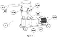
- the electric motor (21.1) transmits the rotation drive movement to the turntable (21.5) in the circular chamber (21.3) through the reducer (21.2).
- Four pressure rollers (21.6) are associated with shafts (21.7) perpendicular to the turntable (21.5) from the lateral surfaces.
- the angle of the shafts (21.7) with each other is preferably 90 degrees.
- the pressure rollers (21.6) are associated tangentially to the surface of the perforated plate (21.8). During movement, they exert a pressing force on the surface.
- the irrigation unit (13) can be designed to be on the recovery unit (21) or to be independent.
- the shafts (21.7) connected to it While the turntable (21.5) moves circularly, the shafts (21.7) connected to it also move. Along with the shafts (21.7), the pressure rollers (21.6) also move circularly in the same direction. Since the pressure rollers (21.6) move on the surface of the perforated plate (21.8), and since these rollers (21.6) are rotatably and freely mounted on the shafts (21.7), the pressure rollers (21.6) also rotate around their own axis. In other words, the pressure rollers (21.6) not only move circularly in the chamber (21.3) together with the turntable (21.5), but also rotate about their own axis. The shafts (21.7) of the pressure rollers (21.6) are mounted on bearings (21.4) outside the chamber (21.3).
- the dough coming into the recovery unit (21) is transferred into the chamber (21.3).
- the dough entering under the pressure rollers (21.6) is forced to the holes (21.8.1) on the perforated plate (21.8).
- Channels (21.6.1) and rabbets (21.6.2) are formed on the pressure rollers (21.6) in order to separate the dough in the appropriate size and shape.
- the rabbets (21.6.2) have a sharp surface form to avoid blockage on the perforated plate (21.8).
- the rabbet (21.6.2) also ensures that the dough is transferred through the holes (21.8.1) without sticking to the roller thanks to its sharp surface, and the dough remaining after transfer is disconnected from the hole (21.8.1).
- the holes (21.8) in the perforated plate (21.8.1) are conical in shape.
- the diameter on the upper surface is larger than the diameter on the lower surface.
- the diameter of the final product passing through the hole decreases from 2 mm to 1 mm and its cross-section is circular. Its length is around 1-2 cm.
- the shape of the product is in the form of spaghetti.
- the flat surfaces (21.8.2) on the perforated plate (21.8.8), other than the holes (21.8.1) serve as pressure surfaces at the point of contact of the pressure rollers (21.6) with the dough and contribute to the kneading of the dough before the semi-finished product is formed. After the final product is obtained, it is transferred to the cigarette maker (2) for the production of cigarettes through the outlet pipe (9) via the pneumatic system.
- the pressure rollers (21.6) may be driven by an external motor.
- Transmission equipments such as sprockets, spur gears, bevel gears, chains, belts, pulleys, etc. to be associated with the external motor can also provide simultaneous drive movement to each of the pressure rollers (21.6).
- the spaghetti-shaped semi-finished product obtained with the inventive system is characterized by a circular diameter in the range of 0.8 - 1 mm (tolerance +0.2 mm) and a length in the range of 2 - 4 cm (tolerance ⁇ 10 mm) and a conical shape, moisture %13.0 - 14.3 (tolerance %0.3), product temperature 25 - 35°C (tolerance ⁇ 5°C).
- Figures 9-10 show the structure of the pressing rollers (21.6) arranged in spherical form.
- the surface area on which the spherical pressing roller (21.6) contacts the dough is narrower and the pressure force it exerts is higher. For this reason, the spherical pressing rollers (21.6) knead the dough more thoroughly and are more effective in forcing the dough out of the holes (21.8.1).
- spherical pressing rollers (21.6) have less friction on the flat plate and are easier to move than cylindrical ones. In addition, rotation can be achieved with less drive force.
- channels (21.6.1) and rabbets (21.6.2) are formed on the spherical structures.
- FIGS 11-12 show moving pressure rollers (21.6) eccentrically.
- the pressure roller (21.6) basically consists of two parts. The first is the eccentric shaft (can be splined, geared, etc.) and the second is the pressure roller (21.6) itself.
- the pressure roller (21.6) is eccentrically mounted on the eccentric shaft (21.12). In case of any wear effect, it can be disassemble, but only the pressure roller (21.6) is removed from the system and the eccentric shaft (21.12) remains attached to the turntable (21.5).
- the eccentric shaft (21.12) moves, the pressure roller (21.6) on it will also move in the same direction, and the distance between the surface of the perforated plate (21.8) and the center of the pressure roller (21.6) will decrease or increase depending on the movement.
- the eccentrically moving pressing rollers (21.6) contact different portions of the dough evenly, resulting in a dough with a more homogeneous consistency.
- Figures 13-14 show views of the perforated plate (21.8) with different hole (21.8.1) shapes.
- Figure 13 shows a perforated plate (21.8) arranged with non-uniform geometric shapes. For example; spiral (auger) and eccentric shapes are given.
- These semi-finished shapes that will come out of the recovery machine (21) are shaped according to the structure of the hole (21.8.1), and therefore, for the spiral sample, the hole (21.8.1) structure must also be drilled on the perforated plate (21.8) in spiral form.
- a person skilled in the art should not only be limited to these images, but should also be aware that different non-uniform geometric shapes can be obtained with holes (21.8.1) that do not have a uniform geometric structure to be drilled on the perforated plate (21.8).
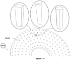
- Figure 14 shows regular geometric shapes.
- the semi-finished product that will come out of the machine can have any form from polygonal structures such as triangle, quadrilateral, pentagon, hexagon, etc.
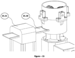
- FIG 15 shows the outlet conveyor (21.10) and cooling unit (21.11) integrated into the recovery unit (21).
- the outlet conveyor (21.10) provides an alternative solution for transporting the products instead of the outlet pipe.
- the cooling unit (21.11) provides the function of cooling the high temperature semi-finished products. It brings the semi-finished products to an average range of 20-25°C.
- the cooling unit (21.11) can be positioned on the conveyor (21.10) integrated in the recovery unit (21) or at the bottom of the chamber (21.3).
- Figures 16-17 show another alternative operation of the pressing rollers (21.6) that enable the dough to be processed in the recovery unit (21).
- bevel gears (21.13) and bevel pinion gears (21.14) are used.
- the bevel pinion gears (21.14) may be at least one.
- the pressure rollers (21.6) are associated with the bevel pinion gears (21.14) at an angle and eccentrically.
- the spherical pressing rollers (21.6) will be able to rotate around its own axis and provide up-and-down movement, both to knead the dough effectively and to apply the pressing force to the dough for allowing the dough to exit the holes (21.8.1).
- the perforated plate (21.8) in Figure 16 has a circular shape
- the perforated plate in Figure 17 has a spherical shape.
- the printing rollers (21.6) are driven by an external motor.
- the motor (21.1) moves the spherical perforated plate (21.8) in a circular direction through the lower drive shaft (21.15) by means of the reducer (21.2).
- the pressure rollers (21.6) move only around its axis, while the spherical perforated plate (21.8) moves clockwise or counterclockwise.
- FIGs 19-20 show another different way of operation of the pressure rollers (21.6).
- the perforated plate (21.8) is flat and rectangular in contrast to the other views.
- a person skilled in the art should not only be aware of the rectangular cross-section of the perforated plate (21.8), but should also recognize that it can belong to any of the polygonal views: triangular, square, pentagonal, hexagonal, etc.
- the perforated plate (21.8) in Figure 19 is fixed and has rack gear (21.16) integrated into its sides.
- the rack gear (21.16) are fixed in their positions and the pressure rollers (21.6) move back and forth linearly through the movement of the spur gears (21.17) on their axis.
- the situation is different.
- an external small servo motor (21.18) moves the pressure rollers (21.6) around its axis and the piston (21.19) moves the perforated plate (21.8) back and forth linearly.
- wheels can be integrated in the corners.
- the piston can be pneumatic, hydraulic or magnetically driven.
- Figures 21-22 show another embodiment of the recovery machine (21).
- the main motor assembly (21.1) is integrated to the upper part of the chamber (21.3) and the bevel gear (21.13) is driven from the top to rotate the bevel pinion gears (21.14).
Landscapes
- Manufacturing Of Cigar And Cigarette Tobacco (AREA)
Abstract
Description
- The present invention relates to a machine for recovering tobacco dust and tobacco stem, which cannot be used in cigarette production facilities and which are considered as waste, into the cigarette production line.
- Cigarette paper, filter, glues and cork tip paper are used as raw materials during the production of a loosie. Tobacco is transferred from the tobacco feeding line to the cigarette makers (wrapping process). During cigarette wrapping, tobacco stems and tobacco dusts that are not suitable for wrapping and do not fit in cigarette paper are separated by the system. Those separated substances are sent to different units to be recycled back to the cigarette maker.
- It is a known fact that tobacco dusts cannot be utilised during cigarette making. However, since tobacco dusts are not considered as waste by themselves, the idea of using them together with tobacco stems in order to recycle them into the system is evaluated in certain systems in the present art. For example;
- The patent application numbered
TR2021013986 - The adhesive liquids used before the wrapping process affect the quality of tobacco products. Especially it affects the natural taste and aroma of tobacco. Since the natural flavour and aroma of tobacco is changed, it causes tobacco products to be disliked by the user. In addition, residues of chemicals in the adhesive liquids may remain on the tobacco and may cause health problems when consumed. At the same time, the separation process performed with a cutting tool may cause unwanted fragmentation or deformation of tobacco dust.
- In semi-finished products produced with the existing techniques, the mixing process is generally carried out before the mixture (tobacco dust + tobacco stem + tobacco crumb + pulverised water vapour or adhesive liquid) is sent to the pressure and cut rollers. But, a complete homogenisation of the mixture cannot be achieved in the existing techniques.
- The dimensions of the semi-finished products formed during the recovery of tobacco dust and tobacco stem are very important when they are fed back to the cigarette making machines. First of all, the size and structural features of semi-finished products are important in order to be properly wrapped in cigarette papers. Due to the weight of the semi-finished product caused by the size, the heavy ones fall to the ground in the vacuum chambers of the cigarette machine, and the ones with a suitable weight are pulled from the vacuum chamber and sent to the relevant section of the cigarette maker, then cigarette wrapping process is realised. In semi-finished products produced with the existing technique, a loss of 60%-80% is observed in this section, and operating costs increase by sending them to recovery machines or facilities for reprocessing. Since the semi-finished products produced in the current technique and passed through the pressure rollers are in flat form, the degree of adhesion to the tobacco in the cigarette paper is low. Due to the low adhesion, it is observed that the tobacco falls from the ends of the cigarettes during transport from the cigarette making machines or when the user removes the cigarette from the packet.
- Another factor determining the quality of semi-finished products is the thickness. Since semi-finished products produced with current techniques are generally subjected to cutting with knives or mincing with choppers, the thickness of semi-finished products is relatively more than optimum values and this directly affects the burning quality of the cigarette. In semi-finished products with high thickness, the tobacco stem affects the burning negatively and the cigarette goes out quickly. Therefore, this causes customer dissatisfaction.
- Another factor that determines the quality of loosie is the moisture factor. According to the specified standards, the humidity range is expected to be around 13,0% - 14,3%. If the semi-finished product is humid, condensation will occur when the cigarette is exposed to the external environment and black and brown stains will appear on the cigarette paper. Along with humidity, the temperature factor is also important, because if the temperature is more or less than the optimum values, it affects the nicotine and sugar content in the cigarette.
- Another way of utilisation of cigarette tobacco dusts in the current technique is to convert them into sheets. Tobacco dusts stored in dust collection units are sent to certain facilities abroad to be converted into sheet (reconstituted tobacco). These products are then sent to our country and these products are mixed with some tobacco types and finely cut. Therefore, this process carried out abroad is more attractive for tobacco producers in our country in terms of cost. An example of this situation is described in
CN116687047A application. - In the present technique, it is known that reconstituted tobacco sheets are produced by extruder-and-rolling method. In this technique, the head shape of the extruder, screw pressure level are important and carboxyl methylcellulose (CMC) and propylene glycol (PG) are also used. Carboxyl methylcellulose is generally used as a binder and propylene glycol as a plasticiser. These materials affect the quality of tobacco as already mentioned above. At the same time, these materials can lead to the formation of additional toxic substances at high temperatures.
- The patent application numbered
US6840248 describes a method and machine for the recovery of tobacco dust. The invention discloses a machine or production line for the making of smokers' products is put to use in that it is gathered and agglomerated into particles having or exceeding a required size. The method comprises the method of collecting the dust and, if the dust is larger than a certain size, processing it. In this invention, only tobacco dusts are focussed. - Homogenisation of recycled semi-finished products is an important issue in tobacco industry. Different tobacco plants (Burley, Virginia, Oriental types) are blended in different proportions in cigarette. These ratios directly determine the cigarette smoking flavour and burning characteristics. Failure to ensure homogenisation during blending leads to non-standard flavours of cigarettes and causes dissatisfaction among consumers. In addition, the homogenisation rate of the semi-finished product and the number of times the cigarette is smoked, which is referred to as "number of puffs" in the cigarette industry, are directly related to each other. Since the homogenisation rate of semi-finished products produced with the current techniques cannot be ensured correctly, it is not possible to achieve the same number of puffs in each loosie. As a result, this directly affects the quality standard of the product.
- In the existing tobacco recovery facilities, tobacco recovered with tobacco stem + tobacco dust mixture is transported to the cigarette maker with pneumatic systems. While being transported by pneumatic system, the recovered products in the pipe hit the inner walls of the pipe due to the air velocity and cause crumbling and disintegration. This causes the loosie to turn into tobacco dust again before it enters the cigarette maker that forms a lot of loosie from mixture of tobacco stem and tobacco dust. Therefore, the recovery efficiency is significantly reduced. At the same time, this crumbling and disintegration causes rapid wear of the rails located in the vacuum chamber area of the machine forming the cigarette rod and the blades of the part of the cigarette wrapping machine, called VE fan, which enables the cigarette maker to transfer the dust accumulated on the machine parts to the central dust collector. If this wear occurs on the rails of the vacuum chamber, a lot of waste cigarettes are produced because the cigarette wrapping machine cannot roll the cigarette rod properly and seriously increases the production costs.If there is a wear on the blades of the so-called VE fan, which is the main fan, the dust to be transferred to the central collection cannot produce the minimum differential pressure and air flow rate required for the proper operation of the cigarette wrapping machine, so the cigarette wrapping machine starts to make a large number of waste cigarettes. In the meantime, the production efficiency decreases as the speed of the cigarette maker decreases. In addition to this, the cost increases a lot with the replacement of the main fan called VE fan (it is a costly fan).
- The patent application numbered
US2011309559A1 describes a machine for shaping and sizing a plant containing cellulose. The machine is basically based on the extrusion method. The aim of the invention is to obtain the final product by compressing the material to be fed from the hopper with a certain pressure and temperature and passing through a cone-shaped structure at the end of the machine with notch-shaped channels around it. The quality of the final product has become possible with the extrusion temperature and minimum water addition. However, the equipment used in extrusion systems are quite costly and energy consumption is quite high. The production of some forms in tobacco production is not possible with extrusion machines, and the extrusion temperature and other factors must be adjusted at the most appropriate values in order to process the clove dusts + tobacco stems mentioned in the related document. Therefore, labour cost will also increase within the scope of process engineering for this process. - The patent application numbered
WO2022053835A1 describes a machine and method for obtaining a discontinuous tobacco from tobacco stems. In the relevant document, tobacco dusts and/or tobacco stems are first subjected to a pre-treatment and then sent to a conveyor line or extruder for processing. The pre-treated tobacco dust and tobacco stems are moistened while being combined. Then, the extrusion machine is adjusted to a certain temperature and screw pressure value and the final tobacco is obtained. In the final tobacco production, the cooling unit is especially important in extrusion machines. - Some disadvantages have been observed in tobacco production in the extrusion systems mentioned above. The characteristic features that cannot be ignored while obtaining tobacco in the tobacco industry are; smell, taste, consistency, texture, ease during cigarette wrapping, homogenisation, ignition factor and humidity. Since tobacco tends to burn due to its structure and high temperatures cause unwanted chemical changes in tobacco, resulting in unpleasant smells. In addition, the high-temperature final product coming out of the extruder will be exposed to cold air coming from a cooling unit immediately and this will constitute a shock effect on the product and will cause a rapid loss of moisture.
- Consequently, there is a need for a new technology that can overcome the disadvantages mentioned above.
- The main purpose of our invention is to integrate our machine into existing tobacco production facilities and to obtain a recovered tobacco unlike the existing methods.
- Our invention is a system that aims to reprocess the dust and tobacco stem, which are thrown away or buried into the soil in cigarette production facilities, and recycle them to the cigarette maker.
- Unlike the existing techniques, our invention aims to obtain dough mixture from tobacco dust and tobacco stem. Liquid water is used instead of water vapour while constituting dough and homogenisation is achieved at better rates. Before obtaining dough, tobacco dust and tobacco stem are firstly mixed in a dry environment and then water is added. When water is added to the dry mixture, the water is distributed more homogenously and allows the water to spread more evenly on each particle. Making the dry mixture before the dough is obtained allows the amount and proportions of the ingredients to be determined more precisely.
- The main reason for using liquid water instead of spray water vapour is that tobacco dust, tobacco crumb and tobacco stem penetrate each other better during mixing. At the same time, in semi-finished products produced by this method, the nicotine and tar values required by the legal authorities in each cigarette can be achieved in accordance with the standard. The number of puffs of produced cigaratte by this method is also stable (provided that the smoke inhalation rate remains constant).
- Our invention aims to obtain a tobacco in a different form compared to the tobacco obtained and recovered with the existing techniques. This form obtained is in the form of spaghetti and has a circular cross-section and a conical shape. The diameter varies between 0.8 mm and 1 mm. Its length can be between 2 cm and 4 cm. With the spaghetti form, tobacco is distributed more homogeneously on the cigarette paper during cigarette wrapping and more tobacco is placed per loosie. Thanks to this form, cigarette quality is improved. With the spaghetti form, the efficiency of the facilities in the production line connected to our system has been increased and it is aimed to make the cigarette maker work faster with easier wrapping process. At the same time, with this form of tobacco, faster burning of tobacco products is ensured. Because, this homogenous structure spreads the heat at better rates. With the conical shape of the tobacco, the air flow in the cigarette is optimised and the degree of burning is increased.
- Holes with the circular cross-section and conical structure of the perforated plate enables the dust + stem and tobacco particles to sit in a wide pit without blocking the perforated plate. At the same time, when the spaghetti shaped product is fed to the cigarette maker, the conical structure provides an additional adhesion to the other tobaccos in the chopped tobacco blend in the cigarette. In addition, the semi-finished product (tobacco) going to the cigarette packet is prevented from falling off the end of the wrapped cigarette rod during the transfer stage. Furthermore, the tobacco is prevented from falling out when the customer removes the cigarette from the packet and during the combustion of the tobacco.
- If the length of the semi-finished product to be obtained is in the range of 2 cm to 4 cm, the product will be slightly shortened by the trimming impact of the trimming discs working during cigarette wrapping in the cigarette maker and will be wrapped in cigarette paper with other tobacco blends. The semi-finished product having a long structure will provide a fringed structure to the related tobacco blends. The humidity range of the semi-finished product obtained with our inventive machine is between %13 and %14.3.
- In order to obtain the aforementioned tobacco form, our inventive system has a pressure roller structure that rotates circularly in the chamber according to the centre with the effect of the rotary table. At the same time, pressure rollers make a circular movement around its own axis. This pressure roller structure has a cylindrical structure and can move easily on the perforated plate. The pressing rollers mix the dough with the effect of centrifugal force and knead it on the perforated plate at the same time. In this way, better adhesion and shaping of the dough is ensured and tobacco is obtained by forcing the dough to pass through the holes in an appropriate way. The size of the tobacco is determined by the rabbets formed on the roller.
- Mixing and kneading the dough provides better adhesion and shaping of the dough, increases the homogenisation of tobacco dust and stems in the dough and the flavour of the taste of the cigarette due to homogenisation.
- One of the main advantages of our system is that the tobacco recovery is around 60-80%. Considering the current state of the art, this rate will provides that our inventive system will take its place as an indispensable recovery unit in the market. The structure of the tobacco semi-product obtained is thin, and light. Also, it makes easier to wrap cigaratte.
- Our system mixes tobacco dust and tobacco stem with liquid water instead of pulverised water. In other words, in the state of the art, tobacco stem and tobacco dust are processed after being glued together, whereas in our invention, tobacco stem and tobacco dust are mixed with liquid water and then processed. In addition, in obtaining semi-finished products with dough, the tobacco has a more homogeneous structure, the tobacco particles are more homogeneously distributed and easier to shape. Likewise, since our invention is based on the idea of dough obtained from tobacco dust and tobacco stem as input material, it aims to obtain semi-finished products by using both mixing, kneading and forcing methods in the system. Therefore, when the tobacco dust and tobacco stem, which are already mixed at the initial stages in the cigarette production sector, come to the recovery unit, they are subjected to mixing and kneading process steps in order to get more homogenous consistency.
- The body part of our machine acts as a closed chamber formed from a cylindrical cross section. Since it is not possible to re-mix and knead the dough to be obtained with the mixture with the effect of gravity as in the machines of the existing technique, a stable and flat floor was needed. Therefore, the perforated plate integrated into the body plays an important role in both mixing, kneading and obtaining semi-finished products by providing this function. Since our invention works with the centrifugal principle, it also acts as a closed box to prevent product splashing around. Thanks to its covered body structure, tobacco beetle, moth and worms are prevented from accessing the product during the production of semi-finished products. During the kneading of the dough, the dough consistency efficiency is increased by cutting the contact of the dough with the air.
- It is aimed to provide high capacity output of the semi-finished product in the form of spaghetti with a dimensionally small machine thanks to structure of the rotary table in our invention.
- The pressure rollers associated with the turntable perpendicular to the lateral planes do not cause blockages in the holes while pressing the plate during the mixing and kneading process. If they are associated perpendicular to the top or bottom of the turntable, blockages will be observed in the perforated plates. Also, smaller cross-sectional areas will be needed for kneading and pressing, and more rollers will be used. The assembly and de-assembly of the rollers associated from lateral planes is simpler and maintenance time during routine cleaning is minimized.
- In the one embodiment of our inventive system, a pressing roller that moves eccentrically with an eccentric shaft and a spherical shaped pressing roller are used. The pressure roller moving with the eccentric shaft acts on different parts of the dough evenly and ensures that the dough has a more homogeneous consistency. At the same time, the eccentric movement facilitates the passage of the dough through the holes and the eccentricity also ensures that the dough is swept backwards on the perforated plate surface during the kneading process. Therefore, blockage problems are further reduced compared to straight (non-eccentric) moving pressure rollers. In addition, since an eccentric shaft is needed for eccentricity, the flat pressure roller and the eccentric shaft are not connected to each other like one-piece. In case the pressure roller wears out, only the pressure roller can be de-assembled on the eccentric shaft without disassembling the entire system, thus it makes maintenance easier. The pressure force is increased as the spherical form pressure rollers have less surface contact on the perforated plate surface compared to flat cylindrical pressure rollers. The spherical pressing rollers are more suitable for dough mixtures with higher density.
- Shapes of the holes of the perforated plates to be used in our invention play an important role in the recovery of various semi-finished tobacco products. For example; it is much more effective for the recovered semi-finished product (tobacco stem + tobacco dust) to be obtained in spiral form to adhere to other tobaccos in the wrapping process on cigarette paper. Thanks to its spiral shape, there will be a more homogeneous burning. The point to be considered here is that; the more indented and protruding the form between the starting point and the end point of the semi-finished product and at different planar points, the higher the degree of adhesion of the semi-finished product to other tobaccos and the burning of the cigarette. The conical shape of the semi-finished product is also an important factor. At the same time, these forms are easier to wrap in cigarette making machines. Spiral shaped tobacco has a tighter structure and provides less consumption while smoking and thus contributes to the tobacco lasting longer. In addition, with the plates with different hole shapes of our system, it will be possible to produce tobacco in different uniform and non-uniform geometries on demand.
- In our inventive system, recovered tobacco is transported by conveyor and the crumbling and disintegration problems mentioned in the existing technique are overcomed and the recovered tobacco is successfully transferred to the cigarette maker. In this way, production cost is reduced and productivity is increased.
- In alternative embodiments of our invention, the perforated plate can also be designed with a spherical form. The spherical form allows the pressure rollers to apply more pressure on the spherical form. This is because the contact area of the pressure rollers on the spherical form will decrease and therefore the pressure force will increase. This configuration can be used to extract the final product when the proportion of stems or fibers is more than 50% in dust + stem mixtures. This is because the hardness of the blend increases directly if the proportion of grain or fiber is higher in the blend. Therefore, it becomes difficult to process. With this invention, it is easier to maintain the process. This function also increases the efficiency of kneading the dough and makes the mix more homogenized.
- In another alternative embodiment of our invention, there are linearly moving pressure rollers. These rollers move back and forth on a flat plate. This alternative solution is used especially in tobacco + dust mixtures to obtain the final product from dough with more than 70% tobacco dust. Since less pressing force will be needed in mixtures with a high dust ratio, a solution can be provided with a simpler mechanism. Since servo motors that consume relatively less energy will be used in this mechanism, the system will be less costly. Likewise, as an alternative to this system, a perforated plate that rotates around its own axis and moves back and forth can also be used instead of reciprocating pressure cylinders. The reciprocating movement of the plate can be achieved with a piston assembly.
- It is easy to install thanks to the easy fixing of the parts that make up the invention, and the costs are low due to the short assembly time. Moreover, the invention has a solid construction.
- The invention will be described with reference to the accompanying figures, so that the features of the invention will be more clearly understood and appreciated, but the purpose of this is not to limit the invention to these certain regulations. On the contrary, it is intended to cover all alternatives, changes and equivalences that can be included in the area of the invention defined by the accompanying claims. The details shown should be understood that they are shown only for the purpose of describing the preferred embodiments of the present invention and are presented in order to provide the most convenient and easily understandable description of both the shaping of methods and the rules and conceptual features of the invention. In these drawings;
- Figure 1
- Schematic view showing a tobacco production facility in the prior art.
- Figure 2
- Schematic view showing the tobacco stem and the part where the tobacco dust is delivered in the prior art.
- Figure 3
- Schematic view showing the blades used during the processing of the tobacco stem in the prior art.
- Figure 4
- Another schematic view showing a tobacco production facility in the priori art.
- Figure 5
- Perspective view of the present invention.
- Figure 6
- Perspective view showing the inner chamber of the inventive system.
- Figure 7
- Detail view of the pressure rollers.
- Figure 8
- Sectional view of the perforated plate.
- Figure 9
- View of the spherical pressure rollers located in the inner chamber of the inventive system.
- Figure 10
- Perspective view of a spherical pressure roller.
- Figure 11
- Perspective view of the eccentric pressure roller.
- Figure 12
- View showing the movement of the eccentric pressure roller on the perforated plate.
- Figure 13
- View of different hole formations in the perforated plate.
- Figure 14
- View showing the hole formations in the perforated plate.
- Figure 15
- Perspective view of the cooling unit and conveyor belt system integrated into the recovery unit.
- Figure 16
- View showing the pressure rollers working with bevel gear system.
- Figure 17
- View of the spherical shaped pressure rollers working with eccentric bevel gear on the fixed spherical perforated plate.
- Figure 18
- View of the spherical shaped pressure rollers working with eccentric bevel gear on the moving spherical perforated plate.
- Figure 19
- View of the pressure rollers moving with a rack and pinion gear system on a fixed flat plate.
- Figure 20
- View showing a piston-driven flat plate and a pressure roller rotating around its axis.
- Figure 21
- Perspective view of a top-mounted recovery unit.
- Figure 22
- View of pressure rollers working with top-driven bevel gear system.
- The figures to help understand the present invention are numbered as indicated in the attached image and are given below along with their names.
-
- 1.
- Tobacco feeding unit
- 2.
- Cigaratte maker
- 3.
- First dust collection pipe
- 4.
- Second dust collection pipe
- 5.
- Dust collection unit
- 6.
- Cyclone
- 7.
- Airlock
- 8.
- Tobacco stem pipe
- 9.
- Separator section
9.1. Separator adjustment flapper
9.2. Separator plate
9.3. Drain pipe - 10.
- Stem processing pipe
10.1. Blades - 11.
- Combining unit
- 12.
- Mixing unit
- 13.
- Irrigation unit
- 14.
- Transmission pipe
- 15.
- Loading rollers and elevator
- 16.
- Conveyor line
- 17.
- First helix line
- 18.
- Metal detector
- 19.
- Mixing silo
- 20.
- Second helix line
- 21.
- Recovery unit
21.1. Motor
21.2. Reducer
21.3. Chamber
21.4. Bearing
21.5. Turntable
21.6. Pressure roller
21.6.1. Channel
21.6.2. Rabbet
21.7. Shaft
21.8. Perforated plate
21.8.1. Hole
21.8.2. Flat surface
21.9. Cover
21.10. Output conveyor
21.11. Cooling unit
21.12. Eccentric shaft
21.13. Bevel gear
21.14. Bevel pinion gear
21.15. Lower drive shaft
21.16. Rack gear
21.17. Spur gear
21.18. Servo motor
21.19. Piston - 22.
- Outlet pipe
- The cigarette production plant in the current technique can be seen in
Figure 1 . Tobacco coming from the tobacco feeding unit (1) is transferred to the cigaratte maker (2) through transfer pipes. The tobacco transferred from the tobacco feeding unit (1) consists of small, medium and large sized tobacco stems and tobacco dusts, and may also contain small substances such as stones, gravels and burrs. While the cigarette maker (2) wraps the incoming tobacco into cigarette paper, the tobacco stem that does not fit into the cigarette paper is sent to the recovery unit (21) via the tobacco stem pipe (8). - While the tobacco coming to the cigarette maker (2) is checked for size and conformity, the tobacco dust that cannot be used is transferred to the first dust collector pipe (3) and the tobacco dust separated during cigarette wrapping is sent to the dust collector unit (5) via the second dust collector pipe (4). As a result, the dusts coming from the first dust collection pipe (3) and the second dust collection pipe (4) are combined in the dust collection unit (5) and sent to a different facility for processing.
- Some of the tobacco dust transferred from the second dust collecting pipe (4) hits the cyclone (6) blades and is transmitted to the combining unit (11) with spiral pipes through the airlock (7). Air lock (7) is used to separate the tobacco dust from the air.
- Tobacco stems coming from the tobacco stem pipe (8) are first sent to the separator section (9) in order to be purified from small-sized materials such as stones, gravel, soil, etc. and heavy tobacco stems with larger dimensions. Through the central vacuum system connected to the separator section (9), the materials that are heavier than the tobacco stem are taken out of the system through the drain pipe (9.3) under the effect of gravity. The types of substances to be discharged from the separator section (9) are adjusted by the separator adjustment valve (9.1) (the valve is connected to the central vacuum system). By adjusting the separator adjustment valve (9.1) and separator plate (9.2), the materials to be discharged are selected according to their weight. Tobacco stems of suitable size to be processed are conveyed to the stem processing pipe (10). With the help of blades (10.1) in the pipe, tobacco stems are cut into smaller sizes and then transferred to the combining unite (11) {
Figure 3 }. - The processed tobacco stem and the separated tobacco dusts are combined in the combining unit (11) shown in
Figure 2 and mixed in dry conditions in the mixing unit (12). During this mixing process, no liquid spraying/transferring is applied, it is completely dry and this process is the first step for a completely homogeneous combination of tobacco stem and tobacco dust. The mixed tobacco dust and tobacco stem are sent to the irrigation unit (13). The nozzles in the irrigation unit (13) perform the injection process. The important point here is that liquid water is injected, not water vapor. The mixed tobacco dust and tobacco stem turns into a dough in the irrigation unit (13). This dough is sent to the recovery unit (21), which is the system of the invention, via the screws in the transfer pipe. Then, the final processing step is started. - The tobacco dust and tobacco stem collection facility in the current technique can be seen in
Figure 4 . The fiber, winnover and tobacco dust boxes (bales) placed on the loading rollers and elevator (15) are lifted up by the elevator and conveyed to the conveyor line (16). The terms fiber and winnover mentioned here refer to tobacco stems. Tobacco stems and tobacco dust are discharged into the conveyor line (16) and transported with the help of the first screw line (17). During transportation, tobacco stems and tobacco dusts pass through the metal detector (18) and if there are metal elements, they are separated here. The tobacco stem and tobacco dusts are poured into the mixing silo (19) where they are mixed dryly by means of mixers. During this mixing process, no liquid spraying/transferring process is applied, it is completely dry and this process is the first step for the completely homogeneous combination of tobacco stem and tobacco dust. The mixed tobacco dust and tobacco stem are sent to the irrigation unit (13). The nozzles in the irrigation unit (13) perform the injection process. The important point here is that liquid water is injected, not water vapor. The mixed tobacco dust and tobacco stem turns into a dough in the irrigation unit (13). With the help of the second helix line (20), this dough is sent to the recovery unit (21), the system of the invention fFigure 4 }. Then, the final processing step is started. - Views of the present invention system are given in
Figure 5-22 . The system basically consists of motor (21.1), reducer (21.2), chamber (21.3), bearing (21.4), turntable (21.5), pressure roller (21.6), shaft (21.7), perforated plate (21.8), cover (21.9), output conveyor (21.10), cooling unit (21.11) and eccentric shaft (21.12). The electric motor (21.1) transmits the rotation drive movement to the turntable (21.5) in the circular chamber (21.3) through the reducer (21.2). Four pressure rollers (21.6) are associated with shafts (21.7) perpendicular to the turntable (21.5) from the lateral surfaces. The angle of the shafts (21.7) with each other is preferably 90 degrees. The pressure rollers (21.6) are associated tangentially to the surface of the perforated plate (21.8). During movement, they exert a pressing force on the surface. The irrigation unit (13) can be designed to be on the recovery unit (21) or to be independent. - While the turntable (21.5) moves circularly, the shafts (21.7) connected to it also move. Along with the shafts (21.7), the pressure rollers (21.6) also move circularly in the same direction. Since the pressure rollers (21.6) move on the surface of the perforated plate (21.8), and since these rollers (21.6) are rotatably and freely mounted on the shafts (21.7), the pressure rollers (21.6) also rotate around their own axis. In other words, the pressure rollers (21.6) not only move circularly in the chamber (21.3) together with the turntable (21.5), but also rotate about their own axis. The shafts (21.7) of the pressure rollers (21.6) are mounted on bearings (21.4) outside the chamber (21.3).
- The dough coming into the recovery unit (21) is transferred into the chamber (21.3). The dough entering under the pressure rollers (21.6) is forced to the holes (21.8.1) on the perforated plate (21.8). Channels (21.6.1) and rabbets (21.6.2) are formed on the pressure rollers (21.6) in order to separate the dough in the appropriate size and shape. The rabbets (21.6.2) have a sharp surface form to avoid blockage on the perforated plate (21.8). When the dough trapped in the channel (21.6.1) is to be transferred through the hole in the perforated plate (21.8), the rabbet (21.6.2) is activated during the rotation of the pressure roller (21.6) and the dough to be transferred is disconnected from the other dough pile and the process is completed. Centrifugal motion is applied during this process. While the channel (21.6.1) and the rabbet (21.6.2) knead the dough on the perforated plate (21.8), the rabbet (21.6.2) also ensures that the dough is transferred through the holes (21.8.1) without sticking to the roller thanks to its sharp surface, and the dough remaining after transfer is disconnected from the hole (21.8.1).
- The holes (21.8) in the perforated plate (21.8.1) are conical in shape. The diameter on the upper surface is larger than the diameter on the lower surface. The diameter of the final product passing through the hole decreases from 2 mm to 1 mm and its cross-section is circular. Its length is around 1-2 cm. The shape of the product is in the form of spaghetti. The flat surfaces (21.8.2) on the perforated plate (21.8.8), other than the holes (21.8.1), serve as pressure surfaces at the point of contact of the pressure rollers (21.6) with the dough and contribute to the kneading of the dough before the semi-finished product is formed. After the final product is obtained, it is transferred to the cigarette maker (2) for the production of cigarettes through the outlet pipe (9) via the pneumatic system.
- In an alternative method, the pressure rollers (21.6) may be driven by an external motor. Transmission equipments such as sprockets, spur gears, bevel gears, chains, belts, pulleys, etc. to be associated with the external motor can also provide simultaneous drive movement to each of the pressure rollers (21.6).
- The spaghetti-shaped semi-finished product obtained with the inventive system is characterized by a circular diameter in the range of 0.8 - 1 mm (tolerance +0.2 mm) and a length in the range of 2 - 4 cm (tolerance ± 10 mm) and a conical shape, moisture %13.0 - 14.3 (tolerance %0.3), product temperature 25 - 35°C (tolerance ± 5°C).
-
Figures 9-10 show the structure of the pressing rollers (21.6) arranged in spherical form. The surface area on which the spherical pressing roller (21.6) contacts the dough is narrower and the pressure force it exerts is higher. For this reason, the spherical pressing rollers (21.6) knead the dough more thoroughly and are more effective in forcing the dough out of the holes (21.8.1). At the same time, spherical pressing rollers (21.6) have less friction on the flat plate and are easier to move than cylindrical ones. In addition, rotation can be achieved with less drive force. Similarly, channels (21.6.1) and rabbets (21.6.2) are formed on the spherical structures. -
Figures 11-12 show moving pressure rollers (21.6) eccentrically. Here, the pressure roller (21.6) basically consists of two parts. The first is the eccentric shaft (can be splined, geared, etc.) and the second is the pressure roller (21.6) itself. The pressure roller (21.6) is eccentrically mounted on the eccentric shaft (21.12). In case of any wear effect, it can be disassemble, but only the pressure roller (21.6) is removed from the system and the eccentric shaft (21.12) remains attached to the turntable (21.5). As the eccentric shaft (21.12) moves, the pressure roller (21.6) on it will also move in the same direction, and the distance between the surface of the perforated plate (21.8) and the center of the pressure roller (21.6) will decrease or increase depending on the movement. The eccentrically moving pressing rollers (21.6) contact different portions of the dough evenly, resulting in a dough with a more homogeneous consistency. -
Figures 13-14 show views of the perforated plate (21.8) with different hole (21.8.1) shapes.Figure 13 shows a perforated plate (21.8) arranged with non-uniform geometric shapes. For example; spiral (auger) and eccentric shapes are given. These semi-finished shapes that will come out of the recovery machine (21) are shaped according to the structure of the hole (21.8.1), and therefore, for the spiral sample, the hole (21.8.1) structure must also be drilled on the perforated plate (21.8) in spiral form. A person skilled in the art should not only be limited to these images, but should also be aware that different non-uniform geometric shapes can be obtained with holes (21.8.1) that do not have a uniform geometric structure to be drilled on the perforated plate (21.8).Figure 14 shows regular geometric shapes. As a result of the formation of the hole (21.8.1) form in a regular geometric shape, the semi-finished product that will come out of the machine can have any form from polygonal structures such as triangle, quadrilateral, pentagon, hexagon, etc. -
Figure 15 shows the outlet conveyor (21.10) and cooling unit (21.11) integrated into the recovery unit (21). The outlet conveyor (21.10) provides an alternative solution for transporting the products instead of the outlet pipe. The cooling unit (21.11) provides the function of cooling the high temperature semi-finished products. It brings the semi-finished products to an average range of 20-25°C. The cooling unit (21.11) can be positioned on the conveyor (21.10) integrated in the recovery unit (21) or at the bottom of the chamber (21.3). -
Figures 16-17 show another alternative operation of the pressing rollers (21.6) that enable the dough to be processed in the recovery unit (21). Here, bevel gears (21.13) and bevel pinion gears (21.14) are used. The bevel pinion gears (21.14) may be at least one. The pressure rollers (21.6), which are connected to the bevel pinion gears (21.14) via the shaft (21.7), rotate around their axis. InFigure 17 , in particular, the pressure rollers (21.6) are associated with the bevel pinion gears (21.14) at an angle and eccentrically. In this way, the spherical pressing rollers (21.6) will be able to rotate around its own axis and provide up-and-down movement, both to knead the dough effectively and to apply the pressing force to the dough for allowing the dough to exit the holes (21.8.1). Note that the perforated plate (21.8) inFigure 16 has a circular shape, while the perforated plate inFigure 17 has a spherical shape. - In
Figure 18 , unlike the previous views, the printing rollers (21.6) are driven by an external motor. Here, the motor (21.1) moves the spherical perforated plate (21.8) in a circular direction through the lower drive shaft (21.15) by means of the reducer (21.2). In other words, in this figure, the pressure rollers (21.6) move only around its axis, while the spherical perforated plate (21.8) moves clockwise or counterclockwise. -
Figures 19-20 show another different way of operation of the pressure rollers (21.6). Here, the perforated plate (21.8) is flat and rectangular in contrast to the other views. A person skilled in the art should not only be aware of the rectangular cross-section of the perforated plate (21.8), but should also recognize that it can belong to any of the polygonal views: triangular, square, pentagonal, hexagonal, etc. The perforated plate (21.8) inFigure 19 is fixed and has rack gear (21.16) integrated into its sides. The rack gear (21.16) are fixed in their positions and the pressure rollers (21.6) move back and forth linearly through the movement of the spur gears (21.17) on their axis. InFigure 20 , the situation is different. Here, an external small servo motor (21.18) moves the pressure rollers (21.6) around its axis and the piston (21.19) moves the perforated plate (21.8) back and forth linearly. To facilitate the movement of the perforated plate (21.8), wheels can be integrated in the corners. The piston can be pneumatic, hydraulic or magnetically driven. -
Figures 21-22 show another embodiment of the recovery machine (21). Here, the main motor assembly (21.1) is integrated to the upper part of the chamber (21.3) and the bevel gear (21.13) is driven from the top to rotate the bevel pinion gears (21.14).
Claims (12)
- A recovery unit (21) that provides the recovery of circular cross-sectioned conical shaped tobacco in the form of spaghetti by using tobacco stem and tobacco dust, which cannot be wrapped in the cigarette maker (2) or is not suitable for wrapping and seen as waste, comprising;- a chamber (21.3) receiving a dough mixture of tobacco stem and tobacco dust with fluid water from the irrigation unit (13),- a rotary table (21.5) which makes a circular movement around its own axis in the chamber (21.3) with the movement from the motor (21.1) and reducer (21.2),- a shaft (21.7) with circular cross-section, one side of which is associated so as to face perpendicular to the lateral surfaces of the turntable (21.5), the other outer wall of which is mounted in fixed bearings (21.4) outside the chamber (21.3),- at least one pressure roller (21.6), which is slidably mounted on the shaft (21.7) and has at least one channel (21.6.1) and rabbet (21.6.2) formed at equal intervals along the entire surface, which makes a circular rotation movement with the drive of the rotary table (21.5) and makes a circular rotation movement around its own axis after contact with the perforated plate (21.5), forces the dough through the holes on the perforated plate (21.8), and cuts its relationship with the main dough after passing it,- a perforated plate (21.8) containing a plurality of conically formed holes (21.8.1) and a flat surface (21.8.2).
- A recovery unit (21) having a chamber (21.3) receiving a dough mixture of tobacco stem and tobacco dust with fluid water from the irrigation unit (13), a rotary table (21.5) which makes a circular movement around its own axis in the chamber (21.3) with the movement from the motor (21.1) and reducer (21.2), a shaft (21.7) with circular cross-section, one side of which is associated so as to face perpendicular to the lateral surfaces of the turntable (21.5), the other outer wall of which is mounted in fixed bearings (21.4) outside the chamber (21.3), at least one pressure roller (21.6), which is slidably mounted on the shaft (21.7) and has at least one channel (21.6.1) and rabbet (21.6.2) formed at equal intervals along the entire surface, which makes a circular rotation movement with the drive of the rotary table (21.5) and makes a circular rotation movement around its own axis after contact with the perforated plate (21.5), forces the dough through the holes on the perforated plate (21.8), and cuts its relationship with the main dough after passing it, a perforated plate (21.8) containing a plurality of conically formed holes (21.8.1) and a flat surface (21.8.2), characterized in that;- a pressure roller (21.6), which is mounted on the eccentric shaft (21.12) in a non-unitary manner and whose center distance relative to the surface of the perforated plate (21.8) is approached and moved away by means of the eccentricity of the shaft,- a perforated plate (21.8) with holes (21.8.1) of irregular geometric form in the form of spirals, eccentrics or regular geometric form in the form of triangles, quadrilaterals, pentagons,- an outlet conveyor (21.10) associated with the outlet part of the chamber (21.3)- a cooling unit (21.11) associated in the chamber (21.3) or on the outlet conveyor (21.10).
- The chamber (21.3) according to Claim 1 or Claim 2, wherein it has circular cross-sectional structure.
- The rabbet (21.6.2) according to Claim 1 or Claim 2, wherein it has a sharp surface.
- The alternative embodiment of pressure roller (21.6) according to Claim 1 or Claim 2, wherein it has a spherical form.
- The recovery unit (21) according to Claim 1 or Claim 2, wherein it has a bevel gear (21.13) and at least one bevel pinion gear (21.14) for driving the pressure rollers (21.6).
- The recovery unit (21) according to Claim 1 or Claim 2, wherein it has pressure rollers (21.6) that are angularly and eccentrically connected to bevel pinion gears (21.17) via shaft (21.7).
- The recovery unit (21) according to Claim 1 or Claim 2, wherein it has spherical shaped perforated plate (21.8).
- The recovery unit (21) according to Claim 9, wherein it has a lower drive shaft (21.15) which drives a spherical perforated plate (21.8).
- The perforated plate (21.8) according to Claim 1 or Claim 2, wherein it has any of the polygon structures such as triangle, quadrilateral, pentagon.
- The recovery unit (21) according to Claim 1 or Claim 2, wherein it has rack gears (21.16) moving the pressure rollers (21.6) together with the spur gears (21.17).
- The piston (21.19) according to Claim 1 or Claim 2, wherein it can be actuated pneumatically, hydraulically or magnetically.
Applications Claiming Priority (1)
| Application Number | Priority Date | Filing Date | Title |
|---|---|---|---|
| TR202401252 | 2024-02-02 |
Publications (1)
| Publication Number | Publication Date |
|---|---|
| EP4449893A1 true EP4449893A1 (en) | 2024-10-23 |
Family
ID=90368828
Family Applications (1)
| Application Number | Title | Priority Date | Filing Date |
|---|---|---|---|
| EP24164479.8A Pending EP4449893A1 (en) | 2024-02-02 | 2024-03-19 | Tobacco recovery machine |
Country Status (1)
| Country | Link |
|---|---|
| EP (1) | EP4449893A1 (en) |
Citations (7)
| Publication number | Priority date | Publication date | Assignee | Title |
|---|---|---|---|---|
| GB1426121A (en) * | 1972-06-21 | 1976-02-25 | Tamag Basel Ag | Process and apparatus for treating tobacco |
| US4632131A (en) * | 1984-07-03 | 1986-12-30 | Philip Morris Incorporated | Foamed, extruded, coherent multistrand smoking articles |
| US6840248B2 (en) | 2000-02-18 | 2005-01-11 | Hauni Maschinenbau Aktiengesellschaft | Method of and apparatus for recovering and recycling tobacco dust |
| US20110309559A1 (en) | 2008-12-18 | 2011-12-22 | Dietmar Franke | Shaping and dimensioning of plant material containing cellulose |
| WO2021107898A1 (en) * | 2019-11-26 | 2021-06-03 | Proface Yazilim Bilisim Makine Techizat Insaat Sanayi Ithalat Ve Ihracat Ticaret Limited Sirketi | A method of bonding the winnower (stem) and dust wastes released at the cigarette production stages on a tobacco winnower |
| WO2022053835A1 (en) | 2020-09-14 | 2022-03-17 | British American Tobacco Exports Limited | A method of processing tobacco fines into a non-continuous tobacco material |
| CN116687047A (en) | 2023-07-19 | 2023-09-05 | 湖北中烟工业有限责任公司 | Reconstituted Tobacco Dust Utilization System |
-
2024
- 2024-03-19 EP EP24164479.8A patent/EP4449893A1/en active Pending
Patent Citations (7)
| Publication number | Priority date | Publication date | Assignee | Title |
|---|---|---|---|---|
| GB1426121A (en) * | 1972-06-21 | 1976-02-25 | Tamag Basel Ag | Process and apparatus for treating tobacco |
| US4632131A (en) * | 1984-07-03 | 1986-12-30 | Philip Morris Incorporated | Foamed, extruded, coherent multistrand smoking articles |
| US6840248B2 (en) | 2000-02-18 | 2005-01-11 | Hauni Maschinenbau Aktiengesellschaft | Method of and apparatus for recovering and recycling tobacco dust |
| US20110309559A1 (en) | 2008-12-18 | 2011-12-22 | Dietmar Franke | Shaping and dimensioning of plant material containing cellulose |
| WO2021107898A1 (en) * | 2019-11-26 | 2021-06-03 | Proface Yazilim Bilisim Makine Techizat Insaat Sanayi Ithalat Ve Ihracat Ticaret Limited Sirketi | A method of bonding the winnower (stem) and dust wastes released at the cigarette production stages on a tobacco winnower |
| WO2022053835A1 (en) | 2020-09-14 | 2022-03-17 | British American Tobacco Exports Limited | A method of processing tobacco fines into a non-continuous tobacco material |
| CN116687047A (en) | 2023-07-19 | 2023-09-05 | 湖北中烟工业有限责任公司 | Reconstituted Tobacco Dust Utilization System |
Similar Documents
| Publication | Publication Date | Title |
|---|---|---|
| EP4090177B1 (en) | Method for manufacturing reconstituted vegetable and/or alkaloid substances and plant for implementing said method. | |
| DE2920025C2 (en) | Device for the continuous production and conveying of plaster mortar or the like | |
| DE2659611A1 (en) | METHOD FOR MANUFACTURING ARTIFICIAL TOBACCO AND A DEVICE FOR EXECUTING THIS METHOD | |
| CN107088459A (en) | A kind of device for making fig fruit powder | |
| CN114929038A (en) | Method for producing tobacco paste and reconstituted tobacco, tobacco-containing film and apparatus for producing reconstituted tobacco | |
| US4702264A (en) | Tobacco leaf processing | |
| JPS5811994B2 (en) | Continuous tobacco sheet forming method | |
| US4754767A (en) | Tobacco material processing | |
| US3053259A (en) | Processing tobacco | |
| US8991404B2 (en) | Process for shredding a tobacco sheet and apparatus | |
| DE7536748U (en) | STIRRER CRUSH MILL FOR THE PRODUCTION OF A PULP TO BE MOLDED TO A SMOKABLE MATERIAL | |
| CN217038028U (en) | Efficient forage grass superfine crusher | |
| TR2024001252A2 (en) | TOBACCO RECOVERY MACHINE | |
| JPH0747547A (en) | Solid fuel production equipment | |
| EP3886614B1 (en) | A method of bonding the winnower (stem) and dust wastes released at the cigarette production stages on a tobacco winnower | |
| AU2006249253B2 (en) | Stock feed process and apparatus | |
| CN119076177B (en) | Raw material crushing device for preparing composite soil remediation agent | |
| EP4491362B1 (en) | Methods and apparatus for the production of straw panels | |
| US858352A (en) | Machine for forming and compressing peat, &c., into blocks or cakes. | |
| CN218654673U (en) | A feeder for cigarette shreds | |
| JPH0426423Y2 (en) | ||
| CN216630963U (en) | Flavouring agent raw materials reducing mechanism for fodder | |
| CN104785336A (en) | Slime filter cake crushing device and method | |
| CN221934152U (en) | A crushing device for pet snack production and proportioning | |
| CN222174225U (en) | Gypsum milling machine |
Legal Events
| Date | Code | Title | Description |
|---|---|---|---|
| PUAI | Public reference made under article 153(3) epc to a published international application that has entered the european phase |
Free format text: ORIGINAL CODE: 0009012 |
|
| STAA | Information on the status of an ep patent application or granted ep patent |
Free format text: STATUS: THE APPLICATION HAS BEEN PUBLISHED |
|
| AK | Designated contracting states |
Kind code of ref document: A1 Designated state(s): AL AT BE BG CH CY CZ DE DK EE ES FI FR GB GR HR HU IE IS IT LI LT LU LV MC ME MK MT NL NO PL PT RO RS SE SI SK SM TR |
|
| STAA | Information on the status of an ep patent application or granted ep patent |
Free format text: STATUS: REQUEST FOR EXAMINATION WAS MADE |
|
| 17P | Request for examination filed |
Effective date: 20241111 |
|
| RBV | Designated contracting states (corrected) |
Designated state(s): AL AT BE BG CH CY CZ DE DK EE ES FI FR GB GR HR HU IE IS IT LI LT LU LV MC ME MK MT NL NO PL PT RO RS SE SI SK SM TR |
|
| STAA | Information on the status of an ep patent application or granted ep patent |
Free format text: STATUS: EXAMINATION IS IN PROGRESS |
|
| RIN1 | Information on inventor provided before grant (corrected) |
Inventor name: OZMEN, ENGIN HUSEYIN |
|
| RAP1 | Party data changed (applicant data changed or rights of an application transferred) |
Owner name: REINVALT ENGINEERING GROUP MAKINA ANONIM SIRKETI |
|
| 17Q | First examination report despatched |
Effective date: 20260310 |
|
| RAP1 | Party data changed (applicant data changed or rights of an application transferred) |
Owner name: COLAKOGLU, OZAN |