EP4447619A1 - Rotation body and light source apparatus - Google Patents
Rotation body and light source apparatus Download PDFInfo
- Publication number
- EP4447619A1 EP4447619A1 EP24166554.6A EP24166554A EP4447619A1 EP 4447619 A1 EP4447619 A1 EP 4447619A1 EP 24166554 A EP24166554 A EP 24166554A EP 4447619 A1 EP4447619 A1 EP 4447619A1
- Authority
- EP
- European Patent Office
- Prior art keywords
- raw material
- plasma
- region
- compartment
- rotation body
- Prior art date
- Legal status (The legal status is an assumption and is not a legal conclusion. Google has not performed a legal analysis and makes no representation as to the accuracy of the status listed.)
- Pending
Links
Images









Classifications
-
- H—ELECTRICITY
- H05—ELECTRIC TECHNIQUES NOT OTHERWISE PROVIDED FOR
- H05G—X-RAY TECHNIQUE
- H05G2/00—Apparatus or processes specially adapted for producing X-rays, not involving X-ray tubes, e.g. involving generation of a plasma
- H05G2/001—Production of X-ray radiation generated from plasma
- H05G2/003—Production of X-ray radiation generated from plasma the plasma being generated from a material in a liquid or gas state
- H05G2/0035—Production of X-ray radiation generated from plasma the plasma being generated from a material in a liquid or gas state the material containing metals as principal radiation-generating components
-
- H—ELECTRICITY
- H05—ELECTRIC TECHNIQUES NOT OTHERWISE PROVIDED FOR
- H05G—X-RAY TECHNIQUE
- H05G2/00—Apparatus or processes specially adapted for producing X-rays, not involving X-ray tubes, e.g. involving generation of a plasma
- H05G2/001—Production of X-ray radiation generated from plasma
- H05G2/008—Production of X-ray radiation generated from plasma involving an energy-carrying beam in the process of plasma generation
- H05G2/0082—Production of X-ray radiation generated from plasma involving an energy-carrying beam in the process of plasma generation the energy-carrying beam being a laser beam
-
- H—ELECTRICITY
- H05—ELECTRIC TECHNIQUES NOT OTHERWISE PROVIDED FOR
- H05G—X-RAY TECHNIQUE
- H05G2/00—Apparatus or processes specially adapted for producing X-rays, not involving X-ray tubes, e.g. involving generation of a plasma
- H05G2/001—Production of X-ray radiation generated from plasma
- H05G2/009—Auxiliary arrangements not involved in the plasma generation
- H05G2/0094—Reduction, prevention or protection from contamination; Cleaning
Definitions
- the present invention relates to a rotation body that accommodates a plasma raw material for generating X-rays and extreme ultraviolet light, and a light source apparatus that includes the rotation body.
- X-rays have been conventionally used for medical, industrial and research applications.
- X-rays are used for such applications as chest radiography, dental radiography, and computed tomography (CT).
- CT computed tomography
- X-rays are used for such applications as non-destructive testing and tomographic non-destructive testing to observe the inside of materials such as structures and welds.
- X-rays are used for such applications as X-ray diffraction to analyze the crystal structure of materials and X-ray spectroscopy (X-ray fluorescence analysis) to analyze the constituent composition of materials.
- EUV light Extreme ultraviolet light having a wavelength of 13.5 nm, which is in the soft X-ray region having a relatively long wavelength among X-rays, has been recently used for exposure light.
- Some EUV light source apparatuses that generate EUV generate high-temperature plasma by applying an energy beam to a plasma raw material such as molten tin or lithium to excite the plasma raw material and extract EUV light from the high-temperature plasma.
- a method of using a laser beam as an energy beam is called laser produced plasm (LPP)
- a method of using discharge is called discharge produced plasma (DPP) or laser assisted discharge produced plasma (LDP).
- Patent Literatures 1 and 3 disclose that metal pellets that are sources of the plasma raw material are intermittently supplied to the rotation body while maintaining a vacuum state in a chamber using a load lock mechanism. This makes it possible to stably and regularly generate EUV light. Although there is a part that reserves the plasma raw material in the vicinity of an irradiation position of a laser beam, the plasma raw material is consumed each time a laser beam is applied and is scattered due to the centrifugal force of the rotation body. For this reason, it is necessary to regularly supply the plasma raw material and perform a stable continuous operation.
- Patent Literatures 1 and 3 do not disclose a supply means of the plasma raw material while Patent Literature 2 provides a supply device of the plasma raw material, for example.
- a raw material can be supplied to a rotation body using this method.
- the rotation body is provided with a bearing on its rotation shaft. Since this bearing has low heat resistance, a heater for melting the plasma raw material is disposed away from the vicinity of the bearing. As a result, the temperature of the rotation body in the vicinity of the rotation shaft is low. When the plasma raw material is added dropwise into this part, the plasma raw material solidifies in the dropped shape, which causes eccentricity of the weight. This also causes a rotational disturbance due to a factor other than the above. This problem can be solved by raising the temperature in the vicinity of the rotation shaft to a temperature at which the plasma raw material reliably melts. However, in this case, the lifetime of the bearing is shortened.
- the region to be irradiated with a laser beam is referred to as an interaction zone and is surrounded by a debris shield.
- this debris shield makes it possible to prevent debris from being generated by laser beam irradiation, when supplying a plasma raw material to be consumed for each EUV light emission, it is difficult to supply a plasma raw material with the configuration shown in Fig. 6 .
- a rotation body is a rotation body included in a light source apparatus that transforms a liquid plasma raw material into plasma by irradiation of an energy beam to extract radiation, including: a shaft circumference compartment; a raw material accommodating compartment; and an entering prevention portion.
- the shaft circumference compartment is a compartment around a rotation shaft for causing the rotation body to rotate.
- the raw material accommodating compartment is spaced apart from the rotation shaft than the shaft circumference compartment and accommodates the plasma raw material, the energy beam entering the raw material accommodating compartment.
- the entering prevention portion is provided at a boundary between the shaft circumference compartment and the raw material accommodating compartment and prevents the plasma raw material from entering the shaft circumference compartment from the raw material accommodating compartment.
- the entering prevention portion may be a wall-shaped member surrounding the shaft circumference compartment.
- the entering prevention portion may be a sealing body that seals the shaft circumference compartment.
- the raw material accommodating compartment may have a raw material supply region to which the plasma raw material is supplied and a raw material holding region that is spaced apart from the rotation shaft than the raw material supply region, the plasma raw material flowing from the raw material supply region to the raw material holding region due to centrifugal force caused by rotation of the rotation body, and the energy beam may be applied to the raw material holding region.
- the rotation body may further include: a bottom portion that includes a bottom perpendicular to the rotation shaft; and a side wall portion that is continuous to a peripheral edge of the bottom and has a side surface forming a wall against the bottom, the shaft circumference compartment and the raw material supply region being located on the bottom, the raw material holding region being located on the side surface.
- the rotation body may further include a shield portion that surrounds a raw material holding space with the side surface, the raw material holding space being a space around the raw material holding region.
- the rotation body may further include a raw material passage channel that connects the raw material supply region and the raw material holding region to each other, the plasma raw material flowing from the raw material supply region to the raw material holding region via the raw material passage channel.
- the shield portion may include a ceiling portion that is continuous to the side wall portion and an inner wall portion that is continuous to the ceiling portion.
- the raw material passage channel may be an opening between the inner wall portion and the bottom portion.
- the raw material passage channel may be a pipe that connects the raw material supply region and the raw material holding region to each other.
- the rotation body may further include an eave portion that protrudes from the inner wall portion toward the raw material supply region and prevents the plasma raw material added dropwise into the raw material supply region from bouncing back.
- the raw material holding region may include an incident region that the energy beam enters and a connection region that is spaced apart from the rotation shaft than the incident region and is located between the raw material supply region and the incident region.
- the rotation body may further include a raw material passage channel that connects the raw material supply region and the connection region to each other.
- the raw material accommodating compartment may further have a raw material reserving region that is located between the raw material supply region and the raw material holding region, and the plasma raw material may have a first depth from a liquid surface in the raw material reserving region and the plasma raw material may have a second depth from the liquid surface in the raw material supply region, the second depth being shallower than the first depth.
- the rotation body may further include: a bottom portion that includes a bottom perpendicular to the rotation shaft; and a receiving portion that is spaced apart from the bottom portion in a direction along the rotation shaft and has a receiving surface perpendicular to the rotation shaft, the first depth being a depth from the liquid surface to the bottom, the second depth being a depth from the liquid surface to the receiving surface.
- the energy beam may be a laser beam.
- the plasma raw material may be, tin, lithium, gadolinium, terbium, gallium, bismuth, or an alloy including at least one of these materials.
- a light source apparatus is a light source apparatus that transforms a liquid plasma raw material into plasma by irradiation of an energy beam to extract radiation, including: a chamber; a rotation body; and a beam source.
- the chamber is capable of maintaining a vacuum condition.
- the rotation body is disposed inside the chamber and includes a shaft circumference compartment that is a compartment around a rotation shaft of the rotation body, a raw material accommodating compartment that is spaced apart from the rotation shaft than the shaft circumference compartment and accommodates the plasma raw material, the energy beam entering the raw material accommodating compartment, and an entering prevention portion that is provided at a boundary between the shaft circumference compartment and the raw material accommodating compartment and prevents the plasma raw material from entering the shaft circumference compartment from the raw material accommodating compartment.
- the beam source causes the energy beam to enter the raw material accommodating compartment.
- a rotation body and a light source apparatus that are capable of stably supplying a plasma raw material to an irradiation position of an energy beam for a long period of time.
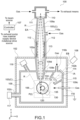
- Fig. 1 is a schematic diagram showing a configuration example of a light source apparatus 100 according to a first embodiment of the present invention
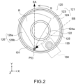
- Fig. 2 is a schematic enlarged view showing part of the light source apparatus 100.
- the light source apparatus 100 is a laser produced plasma (LPP)-based light source apparatus. That is, as shown in Fig. 2 , the light source apparatus 100 is an apparatus that excites a plasma raw material 101 by applying an energy beam EB to the plasma raw material 101 to generate plasma P, extracts radiation R emitted from the plasma P, and uses the extracted radiation R as a light source.
- the radiation R is extreme ultraviolet (EUV), X-rays, or other electromagnetic waves.
- EUV extreme ultraviolet
- the plasma raw material 101 is tin (Sn), lithium (Li), gadolinium (Gd), terbium (Tb), gallium (Ga), bismuth (Bi), or an alloy including at least one of these materials and is liquid.
- molten Sn or Li is used as the plasma raw material 101.
- molten Ga, Ga alloy, Sn compound, or the like is used as the plasma raw material 101.
- Fig. 1 illustrates a schematic cross section of the light source apparatus 100 when the light source apparatus 100 is cut along the horizontal direction at a predetermined height from its installation surface and viewed from vertically above.
- the illustration of the cross section is omitted for portions for which the configuration of the cross section does not need to be explained, in order to facilitate the understanding of the configuration and operation of the light source apparatus 100.
- the X direction is denoted as the left-right direction in the horizontal direction (the positive side of the X axis is the right side and the negative side is the left side)
- the Y direction is denoted as the front-rear direction in the horizontal direction (the positive side of the Y axis is the front side and the negative side is the rear side)
- the Z direction is denoted as the vertical direction (the positive side of the Z axis is the upper side and the negative side is the lower side).
- the orientation in which the light source apparatus 100 is used, and the like are not limited.
- the light source apparatus 100 includes an enclosure 102, a vacuum chamber 103, an energy beam incident chamber 104, a radiation emission chamber 105, a plasma generation mechanism 106, a controller 107, and a raw material supply device 130.
- the raw material supply device 130 is schematically illustrated in Fig. 1 , the detailed configuration will be described below.
- the enclosure 102 is configured such that its external shape is approximately a cube.
- the shape of the enclosure 102 is not limited to a cube and may be an arbitrary three-dimensional shape.
- the enclosure 102 includes an emission hole 102a formed in the front face of the enclosure 102, an incident hole 102b formed in the right side face thereof, and a through-hole 102c formed in the left side face thereof.
- the material of the enclosure 102 is not limited, and a metal is used, for example.
- the radiation R is set to allow an emission axis EA to pass through the emission hole 102a in the front face and extend in the Y direction (front-read direction).
- the radiation R is extracted along the emission axis EA and emitted through the emission hole 102a toward the front side.
- the energy beam EB is set to allow an incident axis IA to extend from the incident hole 102b in the right side face toward the rear side at an oblique angle to the left.
- a beam source 108 that emits the energy beam EB is disposed outside the enclosure 102.
- the beam source 108 is disposed to allow the energy beam EB to enter the inside of the enclosure 102 along the incident axis IA.
- Examples of the energy beam EB include an electron beam and a laser beam.
- the beam source 108 may employ any configurations capable of emitting these energy beams EB.
- the light source apparatus 100 is provided with a chamber section C that includes a plurality of chambers.
- the chamber section C includes the vacuum chamber 103, the energy beam incident chamber (hereinafter, referred to simply as the "incident chamber”) 104, and the radiation emission chamber (hereinafter, referred to simply as the "emission chamber”) 105.
- the vacuum chamber 103 and the incident chamber 104 are connected to each other, and the vacuum chamber 103 and the emission chamber 105 are connected to each other.
- the incident chamber 104 is formed to be located on the incident axis IA of the energy beam EB, and the emission chamber 105 is formed to be located on the emission axis EA of the radiation R. Further, the vacuum chamber 103 is provided with the plasma generation mechanism 106 that generates the plasma P.
- the chamber section C (the vacuum chamber 103, the incident chamber 104, and the emission chamber 105) includes a chamber body 109, an outer protrusion 109a protruding from the front face of the chamber body 109 toward the front side, and two inner protrusions 109b and 109c protruding inward from the inner circumferential face of the chamber body 109.
- a metal material is used as the material of the chamber body 109.
- the chamber body 109 is configured such that its external shape is approximately a rectangular parallelepiped shape, and has its front, rear, left, and right faces that are arranged to face the front, rear, left, and right faces of the enclosure 102, respectively.
- the chamber body 109 has a right-front corner that is disposed to be on the incident axis IA of the energy beam EB, the right-front corner being located between the front face and the right side face.
- an emission hole 109d is formed in the front face of the chamber body 109.
- the emission hole 109d is formed along the emission axis EA of the radiation R, and in line with the emission hole 102a in the front face of the enclosure 102.
- the outer protrusion 109a is formed to protrude from the circumferential edge portion of the emission hole 109d in the chamber body 109 toward the front side.
- the outer protrusion 109a is configured to protrude more forward than the emission hole 102a of the enclosure 102 with being inscribed in the emission hole 102a of the enclosure 102.
- An inner protrusion 109b is formed to protrude inward from the circumferential edge portion of the emission hole 109d inside the chamber body 109.
- the space surrounded by the outer protrusion 109a and the inner protrusion 109b serves as the emission chamber 105.
- the outer protrusion 109a and the inner protrusion 109b themselves, which are the components constituting the emission chamber 105, can also be referred to as the emission chamber.
- the outer protrusion 109a and the inner protrusion 109b may be formed integrally with the chamber body 109, or they may be formed separately and then connected to the chamber body 109.
- the emission chamber 105 is configured to have a cone shape with its central axis being aligned with the emission axis EA of the radiation R.
- the emission chamber 105 is configured to have a large cross-sectional area at its center portion in the direction of the emission axis EA of the radiation R, and have the cross-sectional area being decreased toward the front and rear ends. In other words, the emission chamber 105 is shaped to taper toward the front and rear ends.
- the emission chamber 105 is provided with an opening (aperture) through which the radiation R passes at the front and rear ends.
- a utilization device such as a mask inspection device is connected to the end portion of the emission chamber 105 on the front side (end portion of the outer protrusion 109a on the front side).
- an application chamber 110 is connected as a chamber constituting part of the utilization device.
- the pressure inside the application chamber 110 may be an atmospheric pressure.
- the inside of the application chamber 110 may be purged with gas (e.g., inert gas) from a gas injection channel as necessary.
- the gas inside the application chamber 110 may be exhausted by an exhaust means, which is not shown in the figure.
- a filter film 111 for physically separating a region where the plasma P is generated and the application chamber 110 from each other is provided between the emission chamber 105 and the application chamber 110.
- the filter film 111 is made of a material that is transmissive to the radiation R, and prevents the plasma raw material 101 and debris scattered due to generation of the plasma P from entering the application chamber 110.
- a collector (focusing mirror) 112 for guiding and focusing the radiation R that has entered the emission chamber 105 into the utilization device (inside the application chamber 110) is disposed inside the emission chamber 105.
- the components of the radiation R that enter the emission chamber 105 and are focused are illustrated in hatching.
- a shielding member (central occultation) 113 is disposed inside the emission chamber 105.
- the shielding member 113 is located in line with the emission hole 109d of the chamber body 109, the emission hole 102a of the enclosure 102, and the filter film 111 along with the emission axis EA of the radiation R.
- the shielding member 113 can block the radiation components that are not focused by the collector 112.
- An incident window 114 is provided in the right-front corner of the chamber body 109.
- the incident window 114 is disposed along the incident axis IA of the energy beam EB, and in line with the incident hole 102b in the right side face of the enclosure 102.
- An inner protrusion 109c is formed to protrude inside the right-front corner of the chamber body 109 along the incident axis IA of the energy beam EB from a position surrounding the incident window 114.
- the space surrounded by the inner protrusion 109c serves as the incident chamber 104.
- the inner protrusion 109c and the right-front corner of the chamber body 109 themselves, which are the components constituting the incident chamber 104, can also be referred to as the incident chamber.
- the inner protrusion 109c may be formed integrally with the chamber body 109, or it may be formed separately and then connected to the chamber body 109.
- the incident chamber 104 is configured to have a cone shape with its central axis being aligned with the incident axis IA of the energy beam EB.
- the incident chamber 104 is configured to have a cross-sectional area being decreased toward its end inside the chamber body 109 in the direction of the incident axis IA of the energy beam EB.
- the incident chamber 104 has a tapered shape toward the end thereinside.
- the incident chamber 104 is provided with an opening (aperture) through which the energy beam EB passes at the end thereinside.
- a capturing mechanism is disposed to capture the scattered plasma raw material 101 and debris inside the incident chamber 104.
- a rotary window 115 that is a plate-shaped rotation member for causing the energy beam EB to be transmitted therethrough and capturing the plasma raw material 101 and debris is disposed as the capturing mechanism. Rotating the rotary window 115 makes it possible to increase the substantial area of the beam transmission region of the rotary window 115 and reduce the frequency of replacement of the rotary window 115.
- gas injection channels 116a and 116b are respectively provided in the emission chamber 105 and the incident chamber 104, and gas is supplied to the emission chamber 105 and the incident chamber 104 from a gas supply device, which is omitted in the figure.
- a gas that has high transmittance to the radiation R is supplied to the emission chamber 105.
- a gas that has high transmittance to the energy beam EB is supplied to the incident chamber 104.
- the gases to be supplied to the emission chamber 105 and the incident chamber 104 may be the same type of gas or different types of gases.
- argon or helium can be used as a gas that has high transmittance to both the energy beam EB and the radiation R.
- the type of gas to be supplied to the emission chamber 105 and the incident chamber 104 is not limited. By supplying gas, it is possible to set the pressure inside the emission chamber 105 and the incident chamber 104 to a pressure higher than the pressure inside the vacuum chamber 103, and prevent debris and the like from entering.
- the vacuum chamber 103 In the internal space of the chamber body 109, the space excluding the internal space of the inner protrusion 109b, which serves as the emission chamber 105, and the internal space of the inner protrusion 109c, which serves as the incident chamber 104, serves as the vacuum chamber 103.
- the components themselves constituting the vacuum chamber 103 can also be referred to as the vacuum chamber.
- the chamber body 109 has a portion that protrudes through the through-hole 102c in the left side face of the enclosure 102 to the outside of the enclosure 102, and the portion has an end connected to an exhaust pump 117.
- the specific configuration of the exhaust pump 117 is not limited, and an arbitrary pump such as a vacuum pump may be used.
- the exhaust pump 117 exhausts the inside the vacuum chamber 103 and depressurizes the vacuum chamber 103. This suppresses the attenuation of the radiation R generated in the vacuum chamber 103.
- the inside of the vacuum chamber 103 is not necessarily a vacuum atmosphere, provided that it is a reduced-pressure atmosphere with respect to the incident chamber 104 and the emission chamber 105.
- the inside of the vacuum chamber 103 may be supplied with an inert gas.
- a gas nozzle 118 is disposed to extend in the left-right direction toward the region between the incident axis IA and the emission axis EA.
- the gas nozzle 118 is disposed on the right side face of the chamber body 109 via a seal member or the like.
- the gas nozzle 118 is connected to a gas supply device, which is omitted in the figure, and supplies gas to the inside of the chamber body 109.
- the gas nozzle 118 ejects gas from the right side of the region between the incident axis IA and the emission axis EA toward the left side thereof in the left-right direction. This allows the debris that has been released from the plasma P to move in a direction away from the incident axis IA and the emission axis EA.
- the plasma generation mechanism 106 is a mechanism for generating the plasma P inside the vacuum chamber 103 and emitting the radiation R (X-rays, EUV light). As shown in Fig. 2 , the plasma generation mechanism 106 includes a rotation body 120. As shown in Fig. 2 , the energy beam EB enters the rotation body 120. The rotation body 120 is disposed inside the vacuum chamber 103 such that an irradiation position I of the energy beam EB is placed at the intersection between the incident axis IA and the emission axis EA.
- the rotation body 120 is held to be rotatable as shown by an arrow S in Fig. 2 , and a liquid plasma raw material 101 is supplied thereto from the raw material supply device 130.
- the plasma raw material 101 is supplied to the irradiation position I by rotation of the rotation body 120, and the energy beam EB enters the irradiation position I to generate the plasma P. Details of the plasma generation mechanism 106 and the raw material supply device 130 will be described below.
- the controller 107 controls the operation of each component provided in the light source apparatus 100.
- the controller 107 controls the operation of the beam source 108 and the exhaust pump 117.
- the controller 107 controls the operation of the raw material supply device 130 described below, a rotational drive source, and the like.
- the controller 107 includes hardware circuits necessary for computers, such as CPUs and memories (RAM, ROM).
- a CPU loads a control program stored in a memory into a RAM and executes it to perform various processes.
- a programmable logic device such as field programmable gate array (GPGA), and other devices such as application specific integrated circuit (ASIC) may be used.
- the controller 107 is schematically illustrated as a function block. However, the controller 107 may be designed in any desired manner including the position at which the controller 107 is configured.
- a radiation diagnosis section 119 is provided on the front side of the chamber body 109, in the region spatially connected to the vacuum chamber 103.
- the radiation diagnosis section 119 is disposed at a position at which the radiation R radiated in a direction different from the emission axis EA of the radiation R enters.
- the radiation diagnosis section 119 measures the state of the radiation R emitted from the plasma P.
- the state of the radiation R means the physical state of the radiation R, such as intensity, wavelength, and spectrum of the radiation R.
- the radiation diagnosis section 119 includes a detector that detects the presence or absence of the radiation R and a measurement device that measures the output of the radiation, for example. The measurement results with the radiation diagnosis section 119 are used to diagnose the radiation R or to control the operation of the raw material supply device 130 described below.
- Fig. 3 is a schematic diagram showing a configuration of the plasma generation mechanism 106 and the raw material supply device 130. Note that in Fig. 3 , the enclosure 102, the energy beam incident chamber 104, and the radiation emission chamber 105 are omitted. As shown in Fig. 3 , the raw material supply device 130 is connected to the vacuum chamber 103 of the light source apparatus 100. The raw material supply device 130 is a device that supplies the plasma raw material 101 to the vacuum chamber 103.
- the raw material supply device 130 includes a raw material supply section 131, a raw material replenishment pipe 132, a replenishment valve 133, a raw material tank 134, a raw material supply pipe 135, a supply valve 136, a pressure gauge 137, an exhaust pipe 138, a heating mechanism 139, and a vacuum exhaust device 140.
- the raw material supply section 131 supplies the plasma raw material 101 for replenishing the raw material tank 134.
- the raw material supply section 131 is a mechanism for accommodating the plasma raw material 101 and supplying the necessary amount of the plasma raw material 101.
- the raw material replenishment pipe 132 connects the raw material supply section 131 and the raw material tank 134 and causes the plasma raw material 101 supplied from the raw material supply section 131 to pass therethrough.
- the replenishment valve 133 is provided to the raw material replenishment pipe 132 and maintains the reduced-pressure atmosphere of the raw material tank 134.
- a mechanical valve that opens and closes the raw material replenishment pipe 132 such that the plasma raw material 101 can pass therethrough is used.
- the raw material tank 134 is provided outside the vacuum chamber 103 and reserves the plasma raw material 101 in the liquid state.
- the raw material replenishment pipe 132 and the raw material supply pipe 135 are connected to the raw material tank 134 so as to be communicated with the inside of the raw material tank 134.
- the raw material tank 134 includes the heating mechanism 139.
- the heating mechanism 139 is a mechanism for heating the plasma raw material 101 in the raw material tank 134. As the heating mechanism 139, for example, a heater using a heating wire or the like is used.
- the heating by the heating mechanism 139 maintains the plasma raw material 101 to be supplied from the raw material replenishment pipe 132 to the raw material tank 134 at a predetermined temperature such that the plasma raw material 101 is in the liquid state, regardless of the state at the time of replenishment (a solid state or a liquid state).
- the raw material supply pipe 135 connects the raw material tank 134 and the vacuum chamber 103, and supplies the liquid plasma raw material 101 reserved in the raw material tank 134 to the rotation body 120.
- the raw material supply pipe 135 penetrates the wall surface of the vacuum chamber 103 to connect the raw material tank 134 and the vacuum chamber 103.
- the supply valve 136 is provided to the raw material supply pipe 135 and opens and closes the flow of the plasma raw material 101.
- the pressure gauge 137 is connected to the raw material tank 134 and measures the pressure in the raw material tank 134.
- the exhaust pipe 138 connects the vacuum exhaust device 140 and the raw material tank 134.
- the raw material supply device 130 is disposed vertically above the vacuum chamber 103. This makes it possible to introduce the liquid plasma raw material 101 into the vacuum chamber 103 by its own weight and make the device configuration simple. In addition, by using the raw material supply device 130, it is possible to supply the liquid plasma raw material 101 to the rotation body 120 as necessary. Therefore, it is possible to reduce the reserve amount of the plasma raw material 101, reduce energy consumption, and stably supply the plasma raw material.
- the plasma generation mechanism 106 includes the rotation body 120, a rotational drive source 127, a shaft 128, and a bearing 129.
- the rotational drive source 127 is disposed outside the vacuum chamber 103 and generates rotational power of the rotation body 120.
- the rotational drive source 127 is, for example, a motor.
- the shaft 128 connects the rotational drive source 127 and the rotation body 120 and transmits the rotational power generated by the rotational drive source 127 to the rotation body 120.
- the bearing 129 is disposed between the shaft 128 and the vacuum chamber 103 and allows the shaft 128 to rotate relative to the vacuum chamber 103.
- the rotation body 120 is disposed inside the vacuum chamber 103 and is connected to the shaft 128. As shown in Fig. 3 , the rotation body 120 rotates by the rotation of the shaft 128.
- the rotation axis of the rotation body 120 and the shaft 128 will be referred to as the rotation axis M.
- the rotation axis M is disposed along the vertical direction (Z direction) such that the rotation surface is in the horizontal direction.
- the material of the rotation body 120 is not particularly limited as long as the molten plasma raw material 101 can be accommodated.
- Fig. 4 is a cross-sectional view of the rotation body 120
- Fig. 5 is a plan view of the rotation body 120.
- Fig. 4 shows the cross section of the rotation body 120 taken along the line A-A in Fig. 5 .
- the rotation body 120 includes a body portion 121 and an entering prevention portion 122.
- the side wall portion 124 is a cylindrical wall portion continuous to the peripheral edge of the bottom portion 123.
- the side wall portion 124 may be a cylindrical wall portion provided at a predetermined distance from the rotation axis M.
- the side wall portion 124 has a side surface 124a.
- the side surface 124a is a surface of the side wall portion 124 on the inner peripheral side, is continuous to the peripheral edge of the bottom 123a, and is a surface forming a wall against the bottom 123a.
- the side surface 124a is, for example, a surface perpendicular to the bottom 123a.
- the side surface 124a may be a surface that is inclined on the inner peripheral side or outer peripheral side with respect to the surface perpendicular to the bottom 123, a surface that is inclined on the inner peripheral side or outer peripheral side from a predetermined height with the side of the bottom 123a being perpendicular to the bottom 123a, or the like.
- the entering prevention portion 122 is a wall portion provided on the bottom 123a.
- the entering prevention portion 122 may be a cylindrical wall portion that is provided at a predetermined distance from the rotation axis M and is closer to the rotation axis M than the side wall portion 124.
- the entering prevention portion 122 has a wall surface 122a.
- the wall surface 122a is a surface of the entering prevention portion 122 on the outer periphery side and is continuous to the bottom 123a.
- the wall surface 122a is, for example, a surface perpendicular to the bottom 123a and faces the side surface 124a.
- the rotation body 120 includes a shaft circumference compartment 125 and a raw material accommodating compartment 126.
- the shaft circumference compartment 125 and the raw material accommodating compartment 126 are separated from each other by the entering prevention portion 122.
- the raw material supply region 126a is a region to which the plasma raw material 101 is supplied. Specifically, the raw material supply region 126a is a region of the bottom 123a on the outer periphery side than the entering prevention portion 122.
- the raw material holding region 126b is a region that is spaced apart from the rotation axis M than the raw material supply region 126a, the plasma raw material 101 flowing from the raw material supply region 126a to the raw material holding region 126b due to centrifugal force caused by rotation of the rotation body 120, the energy beam EB being applied to the raw material holding region 126b. Specifically, the raw material holding region 126b is a region on the side surface 124a.
- Fig. 6 is a schematic diagram showing supply of the plasma raw material 101 from the raw material supply device 130 to the rotation body 120.
- liquid droplets D of the plasma raw material 101 are added dropwise from the raw material supply device 130 into the raw material supply region 126a on the bottom 123a while the rotation body 120 rotates.
- the plasma raw material 101 that has been added dropwise flows from the raw material supply region 126a to the side surface 124a, i.e., the raw material holding region 126b due to centrifugal force caused by rotation of the rotation body 120.
- the energy beam EB is applied to the plasma raw material 101 at the irradiation position I on the raw material holding region 126b to generate the plasma P. Since the plasma raw material 101 on the raw material holding region 126b is consumed due to transformation into plasma by application of the energy beam EB, the plasma raw material 101 is continuously supplied to the raw material supply region 126a also during the application of the energy beam EB.
- the plasma generation mechanism 106 has the configuration described above.
- the shape of the rotation body 120 is not limited to the above, and the rotation body 120 only needs to include the shaft circumference compartment 125, the raw material accommodating compartment 126, and the entering prevention portion 122.
- the outer peripheral shape of the body portion 121 is not limited to a circular shape and may be a polygonal shape.
- the shape of the entering prevention portion 122 is also not limited to a cylindrical shape and only needs to be a shape separating the shaft circumference compartment 125 and the raw material accommodating compartment 126 from each other.
- the direction of the rotation axis M is also not limited to a direction along the vertical direction and may be a direction that is inclined from the vertical direction to some degrees.
- the configurations of the rotational drive source 127, the shaft 128, and the bearing 129 can also be changed as appropriate.
- the plasma raw material 101 is added dropwise into the raw material supply region 126a and flows to the raw material holding region 126b by centrifugal force (see Fig. 6 ).
- the plasma raw material 101 is located inside the raw material accommodating compartment 126.
- the shaft circumference compartment 125 is closer to the rotation axis M than the raw material accommodating compartment 126 and is separated from the raw material accommodating compartment 126 by the entering prevention portion 122. For this reason, the plasma raw material 101 is prevented from entering the shaft circumference compartment 125.
- the entering prevention portion 122 If the entering prevention portion 122 is not provided, there is a possibility that the plasma raw material 101 enters the shaft circumference compartment 125 due to scattering of the liquid droplets D, or the like. In this case, when the plasma raw material 101 solidifies in the shaft circumference compartment 125, eccentricity is caused and there is a possibility that a rotational disturbance of the rotation body 120 occurs. As a result, the liquid surface of the plasma raw material 101 fluctuates at the irradiation position I and the state of the radiation R to be emitted becomes unstable. Meanwhile, the plasma raw material 101 can be prevented from solidifying by heating the shaft circumference compartment 125 using a heater or the like. However, since a bearing generally has low heat resistance, the lifetime of the bearing 129 is shortened when heating the shaft circumference compartment 125 using a heater or the like.
- the rotation body 120 since the plasma raw material 101 is prevented from entering the shaft circumference compartment 125, it is unnecessary to heat the shaft circumference compartment 125.
- the plasma raw material 101 can be prevented from solidifying by heating the raw material accommodating compartment 126 that is spaced apart from the rotation axis M, it is possible to prevent a rotational disturbance and make the rotation of the rotation body 120 more stable. Therefore, by using the rotation body 120, it is possible to stably supply the plasma raw material 101 to the irradiation position I for a long period of time, make the state of the radiation R more stable, and achieve a stable operation of the light source apparatus 100 for a long time.
- the rotation body 120 may have the following configuration.
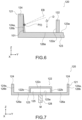
- Fig. 7 is a schematic diagram showing another configuration of the rotation body 120.
- the entering prevention portion 122 may be a sealing body that seals the shaft circumference compartment 125.
- the entering prevention portion 122 includes a wall portion 122b that is provided on the bottom 123a and a top plate portion 122c that closes the space in the wall portion 122b.
- the wall portion 122b may be a cylindrical wall portion that is provided at a predetermined distance from the rotation axis M and is closer to the rotation axis M than the side wall portion 124.
- the top plate portion 122c may be a flat plate shaped portion.
- the plasma raw material 101 can be prevented from entering the shaft circumference compartment 125 by the entering prevention portion 122 that is a sealing body, it is possible to stably supply the plasma raw material 101 to the irradiation position I for a long period of time and make the state of the radiation R more stable.
- the top plate portion 122c does not necessarily need to have a flat plate shape and may suitably have a shape in which the plasma raw material 101 does not accumulate on the top plate portion 122c, such as a curved or conical shape with a central part protruding upwards.
- the entering prevention portion 122 only needs to seal the shaft circumference compartment 125 and may have, for example, a hemispherical shape.
- a light source apparatus according to a second embodiment of the present invention will be described.
- description of configurations and effects similar to those in the light source apparatus 100 described in the above embodiment will be omitted or simplified.
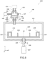
- Fig. 8 is a schematic diagram of the plasma generation mechanism 206 included in the light source apparatus 200 according to the second embodiment.
- the plasma generation mechanism 206 includes the rotation body 220, a rotational drive source 227, a shaft 228, and a bearing 229.
- the rotational drive source 227 is disposed outside the vacuum chamber 103 and generates rotational power of the rotation body 220.
- the rotational drive source 227 is, for example, a motor.
- the shaft 228 connects the rotational drive source 227 and the rotation body 220 and transmits the rotational power generated by the rotational drive source 227 to the rotation body 220.
- the bearing 229 is disposed between the shaft 228 and the vacuum chamber 103 and allows the shaft 228 to rotate relative to the vacuum chamber 103.
- the rotation body 220 is disposed inside the vacuum chamber 103 and is connected to the shaft 228. As shown in Fig. 8 , the rotation body 220 rotates by the rotation of the shaft 228.
- the rotation axis of the rotation body 220 and the shaft 228 will be referred to as the rotation axis M.
- the rotation axis M is disposed along the vertical direction (Z direction) such that the rotation surface is in the horizontal direction.
- Fig. 9 is a cross-sectional view of the rotation body 220
- Fig. 10 is an enlarged view of Fig. 9
- Fig. 11 is a plan view of the rotation body 220.
- Fig. 9 shows the cross section of the rotation body 220 taken along the line B-B in Fig. 11 .
- the rotation body 220 includes the body portion 221, an entering prevention portion 222, and a shield portion 230.
- the body portion 221 includes a bottom portion 223 and a side wall portion 224.
- the bottom portion 223 is a plate-shaped portion and may have a disc shape.
- the shaft 228 is connected to the center of the body portion 221.
- the bottom portion 223 includes a bottom 223a.
- the bottom 223a is a surface of the bottom portion 223 opposite to the shaft 228.
- the bottom 223a is, for example, a surface perpendicular to the rotation axis M, i.e., a horizontal surface.
- the side wall portion 224 is a cylindrical wall portion continuous to the peripheral edge of the bottom portion 223.
- the side wall portion 224 may be a cylindrical wall portion that is provided at a predetermined distance from the rotation axis M.
- the side wall portion 224 has a side surface 224a.
- the side surface 224a is a surface of the side wall portion 224 on the inner peripheral side, is continuous to the peripheral edge of the bottom 223a, and is a surface forming a wall against the bottom 223a.
- the side surface 224a is, for example, a surface perpendicular to the bottom 223a.
- the side surface 224a may be a surface that is inclined on the inner peripheral side or outer peripheral side with respect to the surface perpendicular to the bottom 223a, a surface that is inclined on the inner peripheral side or outer peripheral side from a predetermined height with the side of the bottom 223a being perpendicular to the bottom 223a, or the like.
- the entering prevention portion 222 is a wall portion provided on the bottom 223a.
- the entering prevention portion 222 may be a cylindrical wall portion that is provided at a predetermined distance from the rotation axis M and is closer to the rotation axis M than the side wall portion 224.
- the entering prevention portion 222 has a wall surface 222a.
- the wall surface 222a is a surface of the entering prevention portion 222 on the outer periphery side and is continuous to the bottom 223a.
- the wall surface 222a is, for example, a surface perpendicular to the bottom 223a.
- the shield portion 230 forms a space between the shield portion 230 and the side surface 224a. As shown in Fig. 10 , the shield portion 230 incudes a ceiling portion 231 that is continuous to the side wall portion 224 and an inner wall portion 232 that is continuous to the ceiling portion 231.
- the ceiling portion 231 is a plate-shaped member that is parallel to the bottom portion 223, and the inner wall portion 232 is a wall-shaped member that is parallel to the side wall portion 224.
- the shield portion 230 only needs to form a space between the shield portion 230 and the side surface 224a and may have another shape.
- a raw material passage channel 233 is provided between the inner wall portion 232 and the bottom 223a.
- the raw material passage channel 233 is a gap or an opening and is provided over the entire circumference of the inner wall portion 232.
- the rotation body 220 includes a shaft circumference compartment 225 and a raw material accommodating compartment 226.
- the shaft circumference compartment 225 and the raw material accommodating compartment 226 are separated from each other by the above-mentioned entering prevention portion 222.
- the shaft circumference compartment 225 is a compartment around the rotation axis M, is surrounded by the entering prevention portion 222, and is a compartment on the inner peripheral side than the entering prevention portion 222.
- the raw material accommodating compartment 226 is a compartment that is spaced apart from the rotation axis M than the shaft circumference compartment 225 and accommodates the plasma raw material 101, the energy beam EB entering the raw material accommodating compartment 226.
- the raw material accommodating compartment 226 is a compartment on the outer periphery side than the entering prevention portion 222.
- the raw material accommodating compartment 226 has a raw material supply region 226a and a raw material holding region 226b.
- the raw material supply region 226a is a region to which the plasma raw material 101 is supplied. Specifically, the raw material supply region 226a is a region of the bottom 223a on the outer periphery side than the entering prevention portion 222 and on the inner peripheral side than the shield portion 230.
- the raw material holding region 226b is a region that is spaced apart from the rotation axis M than the raw material supply region 226a, the plasma raw material 101 flowing from the raw material supply region 226a to the raw material holding region 226b due to centrifugal force caused by rotation of the rotation body 220, the energy beam EB being applied to the raw material holding region 226b. Specifically, the raw material holding region 226b is a region on the side surface 224a.
- the shield portion 230 since the shield portion 230 is provided, the raw material supply region 226a and the raw material holding region 226b are spaced apart from each other.
- the space around the raw material holding region 226b is surrounded by the side surface 224a and the shield portion 230.
- this space will be referred to as a raw material holding space G.
- the raw material passage channel 233 is provided between the inner wall portion 232 and the bottom portion 223, the raw material holding space G communicates with the raw material supply region 226a via the raw material passage channel 233.
- Fig. 12 is a schematic diagram showing supply of the plasma raw material 101 from the raw material supply device 130 to the rotation body 220.
- the liquid droplets D of the plasma raw material 101 are added dropwise into the raw material supply region 226a on the bottom 223a from the raw material supply device 130 while the rotation body 220 rotates.
- the dropped plasma raw material 101 flows from the raw material supply region 226a to the raw material holding space G through the raw material passage channel 233 due to centrifugal force caused by rotation of the rotation body 220 and further flows to the side surface 224a, i.e., the raw material holding region 226b.
- the energy beam EB is applied to the plasma raw material 101 at the irradiation position I on the raw material holding region 226b to generate the plasma P. Since the plasma raw material 101 on the raw material holding region 226b is consumed due to transformation into plasma by application of the energy beam EB, the plasma raw material 101 is continuously supplied to the raw material supply region 226a also during the application of the energy beam EB.
- the shield portion 230 is provided with a through path (not shown) through which the energy beam EB and the radiation R pass.
- the through path is a gap or opening provided in the inner wall portion 232.
- the plasma generation mechanism 206 has the configuration as described above.
- the shape of the rotation body 220 is not limited to the above as long as it includes at least the shaft circumference compartment 225, the raw material accommodating compartment 226, the entering prevention portion 222, and the shield portion 230.
- the outer peripheral shape of the body portion 221 is not limited to a circular shape and may be a polygonal shape.
- the shape of the entering prevention portion 222 is also not limited to a cylindrical shape and only needs to be a shape separating the shaft circumference compartment 225 and the raw material accommodating compartment 226 from each other.
- the direction of the rotation axis M is also not limited to a direction along the vertical direction and may be a direction that is inclined from the vertical direction to some degrees.
- the configurations of the rotational drive source 227, the shaft 228, and the bearing 229 can also be changed as appropriate.
- the rotation body 220 since the plasma raw material 101 is prevented from entering the shaft circumference compartment 225, similarly to the first embodiment, it is unnecessary to heat the shaft circumference compartment 225. In addition, since the plasma raw material 101 can be prevented from solidifying by heating the raw material accommodating compartment 226 that is spaced apart from the rotation axis M, it is possible to prevent a rotational disturbance and make the rotation of the rotation body 220 more stable. Therefore, by using the rotation body 220, it is possible to stably supply the plasma raw material 101 to the irradiation position I for a long period of time, make the state of the radiation R more stable, and achieve a stable operation of the light source apparatus 200 for a long time.
- the raw material holding space G is surrounded by the shield portion 230, debris is prevented from scattering outside the raw material holding space G.
- the debris is vapor and smoke of the plasma raw material 101 generated by application of the energy beam EB to the plasma raw material 101 and attenuates the energy beam EB and the radiation R.
- the plasma raw material 101 is supplied to the raw material holding region 226b via the raw material passage channel 233. If the plasma raw material 101 is supplied to a region between the shield portion 230 and the side wall portion 224, there is a possibility that the plasma raw material 101 dispersed in a mist due to scattering of the liquid droplets D adheres to the inside of the shield portion 230 and the through path of the energy beam EB, which affects the light emission performance. Meanwhile, in the case of supplying the plasma raw material 101 via the raw material passage channel 233, it is possible to prevent such adhesion. Therefore, by using the rotation body 220, it is possible to achieve both reduction in debris and supply and introduction of the plasma raw material 101 to/into the irradiation position I.
- the rotation body 220 may have the following configuration.
- Fig. 13 and Fig. 14 are each a schematic diagram showing another configuration of the rotation body 220.
- the shield portion 230 may include a pipe unit 234.
- the pipe unit 234 is connected to lower end of the shield portion 230 and forms a tube-shaped raw material passage channel 233 between the pipe unit 234 and the bottom 223a.
- the pipe unit 234 may be provided over the entire circumference of the shield portion 230 and may be provided at predetermined intervals.
- the shield portion 230 may be provided with an eave portion 235.
- the eave portion 235 protrudes from the inner wall portion 232 toward the raw material supply region 226a and is provided over the entire circumference of the shield portion 230.
- the position of the eave portion 235 may be an upper end of the inner wall portion 232 or a position lower than that.
- an eave portion 236 may be provided to the entering prevention portion 222.
- the eave portion 236 protrudes from the entering prevention portion 222 toward the raw material supply region 226a and is provided over the entire circumference of the entering prevention portion 222.
- the position of the eave portion 236 may be an upper end of the entering prevention portion 222 or a position lower than that.
- the eave portion 235 and the eave portion 236 block the bouncing back of the plasma raw material 101 added dropwise into the raw material supply region 226a to prevent the plasma raw material 101 from scattering onto the shield portion 230 and into the shaft circumference compartment 225.
- the rotation body 220 may be provided with only one of the eave portion 235 and the eave portion 236.
- the rotation body 220 may include the pipe unit 234 shown in Fig. 14 and both the eave portion 235 and the eave portion 236 shown in Fig. 14 .
- the entering prevention portion 222 may be a sealing body structure (see Fig. 7 ) that seals the shaft circumference compartment 225.
- a light source apparatus according to a third embodiment of the present invention will be described.
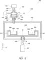
- Fig. 15 is a schematic diagram of a plasma generation mechanism 306 included in a light source apparatus 300 according to the third embodiment.
- the plasma generation mechanism 306 includes a rotation body 320, a rotational drive source 327, a shaft 328, and a bearing 329.
- the rotational drive source 327 is disposed outside the vacuum chamber 103 and generates rotational power of the rotation body 320.
- the rotational drive source 327 is, for example, a motor.
- the shaft 328 connects the rotational drive source 327 and the rotation body 320 and transmits the rotational power generated by the rotational drive source 327 to the rotation body 320.
- the bearing 329 is disposed between the shaft 328 and the vacuum chamber 103 and allows the shaft 328 to rotate relative to the vacuum chamber 103.
- the rotation body 320 is disposed in the vacuum chamber 103 and is connected to the shaft 328. As shown in Fig. 15 , the rotation body 320 rotates by the rotation of the shaft 328.
- the rotation axis of the rotation body 320 and the shaft 328 will be referred to as the rotation axis M.
- the rotation axis M is disposed along the vertical direction (Z direction) such that the rotation surface is in the horizontal direction.
- Fig. 16 is a cross-sectional view of the rotation body 320
- Fig. 17 is an enlarged view of Fig. 16
- Fig. 18 is a plan view of the rotation body 320.
- Fig. 16 shows the cross section of the rotation body 320 taken along the line C-C of Fig. 18 .
- the rotation body 320 includes a body portion 321, an entering prevention portion 322, a shield portion 330, and a receiving portion 340.
- the body portion 321 includes a bottom portion 323 and a side wall portion 324.
- the bottom portion 323 is a plate-shaped portion and may have a disc shape.
- the shaft 328 is connected to the center of the body portion 321.
- the bottom portion 323 includes a bottom 323a.
- the bottom 323a is a surface of the bottom portion 323 opposite to the shaft 328.
- the bottom 323a is, for example, a surface perpendicular to the rotation axis M, i.e., a horizontal surface.
- the side wall portion 324 is a cylindrical wall portion continuous to the peripheral edge of the bottom portion 323.
- the side wall portion 324 may be a cylindrical wall portion provided at a predetermined distance from the rotation axis M.
- the side wall portion 324 has a side surface 324a.
- the side surface 324a is a surface of the side wall portion 324 on the inner peripheral side, is continuous to the peripheral edge of the bottom 323a, and is a surface forming a wall against the bottom 323a.
- the side surface 324a is, for example, a surface perpendicular to the bottom 323a.
- the side surface 324a may be a surface that is inclined on the inner peripheral side or outer peripheral side with respect to the surface perpendicular to the bottom 323a, a surface that is inclined on the inner peripheral side or outer peripheral side from a predetermined height with the side of the bottom 323a being perpendicular to the bottom 323a, or the like.
- the entering prevention portion 322 is a wall portion provided on the receiving portion 340.
- the entering prevention portion 322 may be a cylindrical wall portion that is provided at a predetermined distance from the rotation axis M and is closer to the rotation axis M than the side wall portion 324.
- the entering prevention portion 322 has a wall surface 322a.
- the wall surface 322a is a surface of the entering prevention portion 322 on the outer periphery side and is continuous to a receiving surface 340a of the receiving portion 340.
- the wall surface 322a is, for example, a surface perpendicular to the bottom 323a.
- the shield portion 330 forms a space between the shield portion 330 and the side surface 324a. As shown in Fig. 17 , the shield portion 330 incudes a ceiling portion 331 that is continuous to the side wall portion 324 and an inner wall portion 332 that is continuous to the ceiling portion 331.
- the ceiling portion 331 is a plate-shaped member that is parallel to the bottom portion 323, and the inner wall portion 332 is a wall-shaped member that is parallel to the side wall portion 324.
- the shield portion 330 only needs to form a space between the shield portion 330 and the side surface 324a and may have another shape.
- the inner wall portion 232 is provided with a raw material passage channel 333 that is continuous to the receiving surface 340a.
- the raw material passage channel 333 is a gap or an opening and is provided over the entire circumference of the inner wall portion 332.
- the receiving portion 340 forms the receiving surface 340a.
- the receiving portion 340 is a plate-shaped member that is parallel to the bottom portion 323 and is provided to be spaced apart from the bottom 323a.
- the outer periphery of the receiving portion 340 is connected to the inner wall portion 332, and the inner periphery of the receiving portion 340 is connected to the entering prevention portion 322.
- the surface of the receiving portion 340 opposite to the bottom 323a forms the receiving surface 340a.
- the rotation body 320 includes a shaft circumference compartment 325 and a raw material accommodating compartment 326.
- the shaft circumference compartment 325 and the raw material accommodating compartment 326 are separated from each other by the above-mentioned entering prevention portion 322.
- the shaft circumference compartment 325 is a compartment around the rotation axis M, is surrounded by the entering prevention portion 322, and is a compartment on the inner peripheral side than the entering prevention portion 322.
- the raw material accommodating compartment 326 is a compartment that is spaced apart from the rotation axis M than the shaft circumference compartment 325 and accommodates the plasma raw material 101, the energy beam EB entering the raw material accommodating compartment 326.
- the raw material accommodating compartment 326 is a compartment on the outer periphery side than the entering prevention portion 322. As shown in Fig. 17 , the raw material accommodating compartment 326 has a raw material supply region 326a, a raw material holding region 326b, and a raw material reserving region 326c.
- the raw material supply region 326a is a region to which the plasma raw material 101 is supplied. Specifically, the raw material supply region 326a is a region on the receiving surface 340a.
- the raw material holding region 326b is a region that is spaced apart from the rotation axis M than the raw material supply region 326a, the plasma raw material 101 flowing from the raw material supply region 326a to the raw material holding region 326b due to centrifugal force caused by rotation of the rotation body 320, the energy beam EB being applied to the raw material holding region 326b.
- the raw material holding region 326b is a region on the side surface 324a.
- the raw material reserving region 326c is located between the raw material supply region 326a and the raw material holding region 326b and is a region on the bottom 323a. For this reason, the raw material reserving region 326c is located below the raw material supply region 326a.
- the raw material supply region 326a and the raw material holding region 326b are spaced apart from each other by the raw material reserving region 326c.
- the space around the raw material holding region 326b is surrounded by the side surface 324a and the shield portion 330.
- this space will be referred to as the raw material holding space G.
- the raw material passage channel 333 is provided between the inner wall portion 332 and the receiving surface 340a, and the raw material holding space G communicates with the raw material supply region 326a via the raw material passage channel 333.
- Fig. 19 is a schematic diagram showing supply of the plasma raw material 101 from the raw material supply device 130 to the rotation body 320.
- the liquid droplets D of the plasma raw material 101 are added dropwise into the raw material supply region 326a on the receiving surface 340a from the raw material supply device 130 while the rotation body 320 is stationary.
- the plasma raw material 101 flows on the receiving surface 340a and flows into the raw material reserving region 326c via the raw material passage channel 333.
- a depth L1 of the plasma raw material 101 in the raw material reserving region 326c is deeper than a depth L2 of the plasma raw material 101 in the raw material supply region 326a.
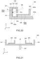
- Fig. 20 is a schematic diagram showing application of the energy beam EB to the plasma raw material 101 in the rotation body 320.
- the rotation body 320 is caused to rotate while the plasma raw material 101 is supplied to the rotation body 320, the plasma raw material 101 reserved in the raw material reserving region 326c moves from the raw material reserving region 326c to the raw material holding region 326b due to centrifugal force caused by rotation of the rotation body 320.
- the energy beam EB is applied to the plasma raw material 101 at the irradiation position I on the raw material holding region 326b to generate the plasma P. Since the plasma raw material 101 on the raw material holding region 326b is consumed due to transformation into plasma by application of the energy beam EB, the plasma raw material 101 is continuously supplied to the raw material supply region 326a also during the application of the energy beam EB.
- the shield portion 330 is provided with a through path (not shown) through which the energy beam EB and the radiation R pass.
- the through path is a gap or opening provided in the inner wall portion 332.
- the plasma generation mechanism 306 has the configuration as described above.
- the shape of the rotation body 320 is not limited to the above as long as it includes at least the shaft circumference compartment 325, the raw material accommodating compartment 326, the entering prevention portion 322, the shield portion 330, and the receiving portion 340.
- the outer peripheral shape of the body portion 321 is not limited to a circular shape and may be a polygonal shape.
- the shape of the entering prevention portion 322 is also not limited to a cylindrical shape and only needs to be a shape separating the shaft circumference compartment 325 and the raw material accommodating compartment 326 from each other.
- the direction of the rotation axis M is also not limited to a direction along the vertical direction and may be a direction that is inclined from the vertical direction to some degrees.
- the configurations of the rotational drive source 327, the shaft 328, and the bearing 329 can also be changed as appropriate.
- the rotation body 320 since the plasma raw material 101 is prevented from entering the shaft circumference compartment 325, similarly to the first embodiment, it is unnecessary to heat the shaft circumference compartment 325. In addition, since the plasma raw material 101 can be prevented from solidifying by heating the raw material accommodating compartment 326 that is spaced apart from the rotation axis M, it is possible to prevent a rotational disturbance and make the rotation of the rotation body 320 more stable. Therefore, by using the rotation body 320, it is possible to stably supply the plasma raw material 101 to the irradiation position I for a long period of time, make the state of the radiation R more stable, and achieve a stable operation of the light source apparatus 300 for a long time. In addition, since the rotation body 320 includes the shield portion 330, it is possible to achieve both reduction in debris and supply and introduction of the plasma raw material 101 to/into the irradiation position I.
- the depth L2 of the plasma raw material 101 in the raw material supply region 326a can be shallower than the depth L1 of the plasma raw material 101 in the raw material reserving region 326c (see Fig. 19 ).
- the receiving portion 340 by causing the receiving portion 340 to be spaced apart from the bottom 323a, the heat of the molten plasma raw material 101 is less likely to transmit to the bottom portion 323 and it is possible to suppress the heat load on the bearing 329.
- the rotation body 320 may have the following configuration.
- Fig. 21 is a schematic diagram showing another configuration of the rotation body 320.
- the rotation body 320 does not necessarily need to include the shield portion 330. Also in this configuration, it is possible to grasp the height of the liquid surface of the plasma raw material 101 by the presence or absence of the liquid surface on the receiving surface 340a and suppress the heat load on the bearing 329.
- one or both of the shield portion 330 and the entering prevention portion 322 may be provided with an eave portion that blocks bouncing back of the plasma raw material 101.
- the entering prevention portion 322 may be a sealing body structure (see Fig. 7 ) that seals the shaft circumference compartment 325.
- a light source apparatus according to a fourth embodiment of the present invention will be described.
- Fig. 22 is a schematic diagram of a plasma generation mechanism 406 included in a light source apparatus 400 according to the fourth embodiment.
- the plasma generation mechanism 406 includes a rotation body 420, a rotational drive source 427, a shaft 428, and a bearing 429.
- the rotational drive source 427 is disposed outside the vacuum chamber 103 and generates rotational power of the rotation body 420.
- the rotational drive source 427 is, for example, a motor.
- the shaft 428 connects the rotational drive source 427 and the rotation body 420 and transmits the rotational power generated by the rotational drive source 427 to the rotation body 420.
- the bearing 429 is disposed between the shaft 428 and the vacuum chamber 103 and allows the shaft 428 to rotate relative to the vacuum chamber 103.
- the rotation body 420 is disposed in the vacuum chamber 103 and is connected to the shaft 428. As shown in Fig. 22 , the rotation body 420 rotates by the rotation of the shaft 428.
- the rotation axis of the rotation body 420 and the shaft 428 will be referred to as the rotation axis M.
- the rotation axis M is disposed along the vertical direction (Z direction) such that the rotation surface is in the horizontal direction.
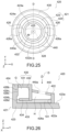
- Fig. 23 is a cross-sectional view of the rotation body 420
- Fig. 24 is an enlarged view of Fig. 23
- Fig. 25 is a plan view of the rotation body 420.
- Fig. 23 shows the cross section of the rotation body 420 taken along the line D-D in Fig. 25 .
- the rotation body 420 includes a body portion 421, an entering prevention portion 422, a shield portion 430, and a lid portion 440.
- the body portion 421 includes a bottom portion 423 and a side wall portion 424.
- the bottom portion 423 is a plate-shaped portion and may have a disc shape.
- the shaft 428 is connected to the center of the body portion 421.
- the bottom portion 423 includes a bottom 423a.
- the bottom 423a is a surface of the bottom portion 423 opposite to the shaft 428.
- the bottom 423a is, for example, a surface perpendicular to the rotation axis M, i.e., a horizontal surface.
- the side wall portion 424 is a cylindrical wall portion continuous to the peripheral edge of the bottom portion 423.
- the side wall portion 424 may be a cylindrical wall portion.
- the side wall portion 424 has a side surface 424a.
- the side surface 424a is a surface of the side wall portion 424 on the inner peripheral side and is continuous to the bottom 423a.
- the side surface 424a has a first side surface 424b and a second side surface 424c.
- the first side surface 424b is a surface of the side surface 424a on the side of the bottom 423a and is provided at a predetermined distance from the rotation axis M.
- the second side surface 424c is a surface of the side surface 424a opposite to the bottom 423a and is provided at a predetermined distance from the rotation axis M and closer to the rotation axis M than the first side surface 424b.
- the entering prevention portion 422 is a wall portion provided on the bottom 423a.
- the entering prevention portion 422 may be a cylindrical wall portion that is provided at a predetermined distance from the rotation axis M and is closer to the rotation axis M than the side wall portion 424.
- the entering prevention portion 422 has a wall surface 422a.
- the wall surface 422a is a surface of the entering prevention portion 422 on the outer side, is continuous to the bottom 423a, and is, for example, a surface perpendicular to the bottom 423a.
- the shield portion 430 forms a space between the shield portion 430 and the side surface 424a.
- the shield portion 430 includes a ceiling portion 431 that is continuous to the side wall portion 424 and an inner wall portion 432 that is continuous to the ceiling portion 431.
- the ceiling portion 431 is a plate-shaped member that is parallel to the bottom portion 423
- the inner wall portion 432 is a wall-shaped member that is parallel to the side wall portion 424.
- the shield portion 430 only needs to form a space between the shield portion 430 and the side surface 424a and may have another shape.
- a raw material passage channel 433 is provided between the inner wall portion 432 and the bottom 423a by a pipe unit 434.
- the pipe unit 434 is connected to the lower end of the shield portion 430 and forms the tube-shaped material passage channel 433 between the pipe unit 434 and the bottom 423a.
- the pipe unit 434 may be provided over the entire circumference of the shield portion 430 and may be provided at predetermined intervals.
- the lid portion 440 connects the entering prevention portion 422 and the inner wall portion 432 to each other.
- the lid portion 440 is provided with a raw material supply port 440a over the entire circumference of the rotation body 420.
- the rotation body 420 includes a shaft circumference compartment 425 and a raw material accommodating compartment 426.
- the shaft circumference compartment 425 and the raw material accommodating compartment 426 are separated from each other by the above-mentioned entering prevention portion 422.
- the shaft circumference compartment 425 is a compartment around the rotation axis M, is surrounded by the entering prevention portion 422, and is a compartment on the inner peripheral side than the entering prevention portion 422.
- the raw material accommodating compartment 426 is a compartment that is spaced apart from the rotation axis M than the shaft circumference compartment 425 and accommodates the plasma raw material 101, the energy beam EB entering the raw material accommodating compartment 426.
- the raw material accommodating compartment 426 is a compartment on the outer periphery side than the entering prevention portion 422.
- the raw material accommodating compartment 426 has a raw material supply region 426a and a raw material holding region 426b.
- the raw material supply region 426a is a region to which the plasma raw material 101 is supplied. Specifically, the raw material supply region 426a is a region of the bottom 423a facing the raw material supply port 440a of the lid portion 440.
- the raw material holding region 426b is a region that is spaced apart from the rotation axis M than the raw material supply region 426a, the plasma raw material 101 flowing from the raw material supply region 426a to the raw material holding region 426b due to centrifugal force caused by rotation of the rotation body 420, the energy beam EB being applied to the raw material holding region 426b.
- the raw material holding region 426b includes an incident region 426c and a connection region 426d.
- the incident region 426c is a region of the raw material holding region 426b that the energy beam EB enters and is a region of the side surface 424a on the second side surface 424c.
- the connection region 426d is a region that is spaced apart from the rotation axis M than the incident region 426c and is located between the raw material supply region 426a and the incident region 426c, and is a region of the side surface 424a on the first side surface 424b.
- the raw material supply region 426a and the raw material holding region 426b are spaced apart from each other.
- the space around the raw material holding region 426b is surrounded by the side surface 424a and the shield portion 430.
- this space will be referred to as the raw material holding space G.
- the raw material passage channel 433 is provided between the inner wall portion 432 and the bottom portion 423, and the raw material holding space G communicates with the raw material supply region 426a via the raw material passage channel 433.
- the space around the raw material supply region 426a is surrounded by the inner wall portion 432, the entering prevention portion 422, and the lid portion 440.
- this space will be referred to as a raw material supply space H.
- Fig. 26 is a schematic diagram showing supply of the plasma raw material 101 from the raw material supply device 130 to the rotation body 420. As shown in the figure, when the liquid droplets D of the plasma raw material 101 are added dropwise into the raw material supply region 426a from the raw material supply device 130 when the rotation body 420 is stationary, the plasma raw material 101 is reserved on the raw material supply region 426a, i.e., in the raw material supply space H.
- Fig. 27 is a schematic diagram showing application of the energy beam EB to the plasma raw material 101 in the rotation body 420.
- the rotation body 420 when the rotation body 420 is caused to rotate while the plasma raw material 101 is reserved in the raw material supply region 426a, the plasma raw material 101 flows from the raw material supply region 426a to the connection region 426d through the raw material passage channel 433 due to centrifugal force caused by rotation of the rotation body 420 and flows from the connection region 426d to the incident region 426c (arrow in Fig. 27 ).
- the energy beam EB is applied to the plasma raw material 101 at the irradiation position I on the incident region 426c to generate the plasma P. Since the plasma raw material 101 on the incident region 426c is consumed due to transformation into plasma by application of the energy beam EB, the plasma raw material 101 is continuously supplied to the raw material supply region 426a also during the application of the energy beam EB. At this time, since the connection region 426d is spaced apart from the rotation axis M than the incident region 426c, the plasma raw material 101 flows to the incident region 426c not from the outer side of the liquid surface but from the inner side of the liquid surface (arrow in Fig. 27 ). Note that the shield portion 430 is provided with a through path (not shown) through which the energy beam EB and the radiation R pass. The through path is a gap or opening provided in the inner wall portion 432.
- the plasma generation mechanism 406 has the configuration as described above.
- the shape of the rotation body 420 is not limited to the above as long as it includes at least the shaft circumference compartment 425, the raw material accommodating compartment 426, the entering prevention portion 422, the shield portion 430.
- the raw material accommodating compartment 426 only needs to have the connection region 426d and the incident region 426c.
- the outer peripheral shape of the body portion 421 is not limited to a circular shape and may be a polygonal shape.
- the shape of the entering prevention portion 422 is also not limited to a cylindrical shape and only needs to be a shape separating the shaft circumference compartment 425 and the raw material accommodating compartment 426 from each other.
- the direction of the rotation axis M is also not limited to a direction along the vertical direction and may be a direction that is inclined from the vertical direction to some degrees.
- the configurations of the rotational drive source 427, the shaft 428, and the bearing 429 can also be changed as appropriate.
- the rotation body 420 since the plasma raw material 101 is prevented from entering the shaft circumference compartment 425, similarly to the first embodiment, it is unnecessary to heat the shaft circumference compartment 425. In addition, since the plasma raw material 101 can be prevented from solidifying by heating the raw material accommodating compartment 426 that is spaced apart from the rotation axis M, it is possible to prevent a rotational disturbance and make the rotation of the rotation body 420 more stable. Therefore, by using the rotation body 420, it is possible to stably supply the plasma raw material 101 to the irradiation position I for a long period of time, make the state of the radiation R more stable, and achieve a stable operation of the light source apparatus 400 for a long time. In addition, since the rotation body 420 includes the shield portion 430, it is possible to achieve both reduction in debris and supply and introduction of the plasma raw material 101 to/into the irradiation position I.
- the raw material holding region 426b has the incident region 426c and the connection region 426d, and the connection region 426d is spaced apart from the rotation axis M than the incident region 426c.
- the plasma raw material 101 flows to the incident region 426c from the inner side of the liquid surface (see Fig. 27 ), it is possible to prevent a disturbance of the liquid surface and make the state of the plasma raw material 101 at the irradiation position I more stable.
- the rotation body 420 may have the following configuration.
- Fig. 28 is a schematic diagram showing another configuration of the rotation body 420.
- the rotation body 420 does not necessarily need to include the lid portion 440. Also in this configuration, it is possible to prevent a disturbance of the liquid surface due to supply of the plasma raw material 101.
- one or both of the shield portion 430 and the entering prevention portion 422 may be provided with an eave portion that blocks bouncing back of the plasma raw material 101.
- the entering prevention portion 422 may be a sealing body structure (see Fig. 7 ) that seals the shaft circumference compartment 425.
- the concepts also include concepts having states in a predetermined range (e.g., ⁇ 10% range) with respect to, for example, “exactly center”, “exactly middle”, “exactly uniform”, “exactly equal”, “exactly the same”, “exactly orthogonal”, “exactly parallel”, “exactly symmetrical”, “exactly extending”, “exactly axial direction”, “exactly circular shape”, “exactly arc shape”, “exactly rectangular shape”, “exactly polygonal shape”, “exactly ring shape”, “exactly cubic shape”, “exactly rectangular parallelepiped shape", “exactly columnar shape”, “exactly disc shape”, and “exactly cone shape”.
- a predetermined range e.g., ⁇ 10% range
- expressions using the term “than” such as “greater than A” and “less than A” are expressions that comprehensively include both concepts that include the case that is equal to A and concepts that do not include the case that is equal to A.
- greater than A is not limited to the case where it does not include “equal to A”, and it also includes “equal to or greater than A”.
- less than A is not limited to “less than A”, and it also includes “equal to or less than A”.
- the various characteristic portions described in the respective embodiments may be arbitrarily combined with each other without distinguishing from each other in the respective embodiments.
- the various effects described above are merely examples and are not limitative, and other effects may also be achieved.
Landscapes
- Physics & Mathematics (AREA)
- Optics & Photonics (AREA)
- Engineering & Computer Science (AREA)
- Plasma & Fusion (AREA)
- X-Ray Techniques (AREA)
- Exposure And Positioning Against Photoresist Photosensitive Materials (AREA)
Abstract
[Object] To provide a rotation body and a light source apparatus that are capable of stably supplying a plasma raw material an irradiation position of an energy beam for a long period of time.
[Solving Means] A rotation body according to an embodiment of the present invention is a rotation body included in a light source apparatus that transforms a liquid plasma raw material into plasma by irradiation of an energy beam to extract radiation, including: a shaft circumference compartment; a raw material accommodating compartment; and an entering prevention portion. The shaft circumference compartment is a compartment around a rotation shaft for causing the rotation body to rotate. The raw material accommodating compartment is spaced apart from the rotation shaft than the shaft circumference compartment and accommodates the plasma raw material, the energy beam entering the raw material accommodating compartment. The entering prevention portion is provided at a boundary between the shaft circumference compartment and the raw material accommodating compartment and prevents the plasma raw material from entering the shaft circumference compartment from the raw material accommodating compartment.
Description
- The present invention relates to a rotation body that accommodates a plasma raw material for generating X-rays and extreme ultraviolet light, and a light source apparatus that includes the rotation body.
- X-rays have been conventionally used for medical, industrial and research applications. In the medical field, X-rays are used for such applications as chest radiography, dental radiography, and computed tomography (CT). In the industrial field, X-rays are used for such applications as non-destructive testing and tomographic non-destructive testing to observe the inside of materials such as structures and welds. In the research field, X-rays are used for such applications as X-ray diffraction to analyze the crystal structure of materials and X-ray spectroscopy (X-ray fluorescence analysis) to analyze the constituent composition of materials. Extreme ultraviolet light (hereinafter, referred to as "EUV light") having a wavelength of 13.5 nm, which is in the soft X-ray region having a relatively long wavelength among X-rays, has been recently used for exposure light.
- Some EUV light source apparatuses that generate EUV generate high-temperature plasma by applying an energy beam to a plasma raw material such as molten tin or lithium to excite the plasma raw material and extract EUV light from the high-temperature plasma. A method of using a laser beam as an energy beam is called laser produced plasm (LPP), and a method of using discharge is called discharge produced plasma (DPP) or laser assisted discharge produced plasma (LDP).
- As an EUV light source apparatus used in LPP, one that excites a raw material by collecting a laser beam on liquid droplets of a plasma raw material to generate plasma is known. Meanwhile, in recent years, a method of supplying a plasma raw material to an irradiation region of a laser beam using the centrifugal force of a rotation body has been developed (see, for example, Patent Literatures 1 to 3). Since this method does not need to supply a plasma raw material in the form of liquid droplets, it is possible to obtain high-intensity radiation with a relatively simple configuration as compared with a method of collecting a laser beam on liquid droplets.
-
- Patent Literature 1:
Japanese Patent Application Laid-open No. 2021-1924 - Patent Literature 2:
Japanese Unexamined Patent Application Publication No. 2008-532228 - Patent Literature 3:
Japanese Unexamined Patent Application Publication No. 2022-530497 - The above Patent Literatures 1 and 3 disclose that metal pellets that are sources of the plasma raw material are intermittently supplied to the rotation body while maintaining a vacuum state in a chamber using a load lock mechanism. This makes it possible to stably and regularly generate EUV light. Although there is a part that reserves the plasma raw material in the vicinity of an irradiation position of a laser beam, the plasma raw material is consumed each time a laser beam is applied and is scattered due to the centrifugal force of the rotation body. For this reason, it is necessary to regularly supply the plasma raw material and perform a stable continuous operation.
- Patent Literatures 1 and 3 do not disclose a supply means of the plasma raw material while Patent Literature 2 provides a supply device of the plasma raw material, for example. A raw material can be supplied to a rotation body using this method. However, it is not always possible to add dropwise the material at the same location depending on the state of a nozzle or the state of the rotation body, which may cause a rotational disturbance.
- Further, the rotation body is provided with a bearing on its rotation shaft. Since this bearing has low heat resistance, a heater for melting the plasma raw material is disposed away from the vicinity of the bearing. As a result, the temperature of the rotation body in the vicinity of the rotation shaft is low. When the plasma raw material is added dropwise into this part, the plasma raw material solidifies in the dropped shape, which causes eccentricity of the weight. This also causes a rotational disturbance due to a factor other than the above. This problem can be solved by raising the temperature in the vicinity of the rotation shaft to a temperature at which the plasma raw material reliably melts. However, in this case, the lifetime of the bearing is shortened.
- Further, in the configuration shown in
Fig. 6 of Patent Literature 3, the region to be irradiated with a laser beam is referred to as an interaction zone and is surrounded by a debris shield. Although this debris shield makes it possible to prevent debris from being generated by laser beam irradiation, when supplying a plasma raw material to be consumed for each EUV light emission, it is difficult to supply a plasma raw material with the configuration shown inFig. 6 . There is a gap between the debris shield and the rotation body, but this gap is not for supplying a plasma raw material but for bringing the fixed debris shield and rotation body as close as possible and causing only the rotation body to rotate. For this reason, it is difficult to supply a plasma raw material through this gap. Therefore, it seems difficult to achieve both debris reduction and supply of a plasma raw material to the irradiation position of a laser beam. - In view of the circumstances as described above, it is an object of the present invention to provide a rotation body and a light source apparatus that are capable of stably supplying a plasma raw material to an irradiation position of an energy beam for a long period of time.
- In order to achieve the above-mentioned object, a rotation body according to an embodiment of the present invention is a rotation body included in a light source apparatus that transforms a liquid plasma raw material into plasma by irradiation of an energy beam to extract radiation, including: a shaft circumference compartment; a raw material accommodating compartment; and an entering prevention portion.
- The shaft circumference compartment is a compartment around a rotation shaft for causing the rotation body to rotate.
- The raw material accommodating compartment is spaced apart from the rotation shaft than the shaft circumference compartment and accommodates the plasma raw material, the energy beam entering the raw material accommodating compartment.
- The entering prevention portion is provided at a boundary between the shaft circumference compartment and the raw material accommodating compartment and prevents the plasma raw material from entering the shaft circumference compartment from the raw material accommodating compartment.
- The entering prevention portion may be a wall-shaped member surrounding the shaft circumference compartment.
- The entering prevention portion may be a sealing body that seals the shaft circumference compartment.
- The raw material accommodating compartment may have a raw material supply region to which the plasma raw material is supplied and a raw material holding region that is spaced apart from the rotation shaft than the raw material supply region, the plasma raw material flowing from the raw material supply region to the raw material holding region due to centrifugal force caused by rotation of the rotation body, and the energy beam may be applied to the raw material holding region.
- The rotation body may further include: a bottom portion that includes a bottom perpendicular to the rotation shaft; and a side wall portion that is continuous to a peripheral edge of the bottom and has a side surface forming a wall against the bottom, the shaft circumference compartment and the raw material supply region being located on the bottom, the raw material holding region being located on the side surface.
- The rotation body may further include a shield portion that surrounds a raw material holding space with the side surface, the raw material holding space being a space around the raw material holding region.
- The rotation body may further include a raw material passage channel that connects the raw material supply region and the raw material holding region to each other, the plasma raw material flowing from the raw material supply region to the raw material holding region via the raw material passage channel.
- The shield portion may include a ceiling portion that is continuous to the side wall portion and an inner wall portion that is continuous to the ceiling portion.
- The raw material passage channel may be an opening between the inner wall portion and the bottom portion.
- The raw material passage channel may be a pipe that connects the raw material supply region and the raw material holding region to each other.
- The rotation body may further include an eave portion that protrudes from the inner wall portion toward the raw material supply region and prevents the plasma raw material added dropwise into the raw material supply region from bouncing back.
- The rotation body may further include a lid portion that connects the inner wall portion and the entering prevention portion to each other, surrounds a raw material supply space with the inner wall portion and the entering prevention portion, and includes a raw material supply port through which the plasma raw material passes, the raw material supply space being a space around the raw material supply region.
- The raw material holding region may include an incident region that the energy beam enters and a connection region that is spaced apart from the rotation shaft than the incident region and is located between the raw material supply region and the incident region.
- The rotation body may further include a raw material passage channel that connects the raw material supply region and the connection region to each other.
- The raw material accommodating compartment may further have a raw material reserving region that is located between the raw material supply region and the raw material holding region, and the plasma raw material may have a first depth from a liquid surface in the raw material reserving region and the plasma raw material may have a second depth from the liquid surface in the raw material supply region, the second depth being shallower than the first depth.
- The rotation body may further include: a bottom portion that includes a bottom perpendicular to the rotation shaft; and a receiving portion that is spaced apart from the bottom portion in a direction along the rotation shaft and has a receiving surface perpendicular to the rotation shaft, the first depth being a depth from the liquid surface to the bottom, the second depth being a depth from the liquid surface to the receiving surface.
- The energy beam may be a laser beam.
- The radiation may be extreme ultraviolet light or X-rays.
- The plasma raw material may be, tin, lithium, gadolinium, terbium, gallium, bismuth, or an alloy including at least one of these materials.
- In order to achieve the above-mentioned object, a light source apparatus according to an embodiment of the present invention is a light source apparatus that transforms a liquid plasma raw material into plasma by irradiation of an energy beam to extract radiation, including: a chamber; a rotation body; and a beam source.
- The chamber is capable of maintaining a vacuum condition.
- The rotation body is disposed inside the chamber and includes a shaft circumference compartment that is a compartment around a rotation shaft of the rotation body, a raw material accommodating compartment that is spaced apart from the rotation shaft than the shaft circumference compartment and accommodates the plasma raw material, the energy beam entering the raw material accommodating compartment, and an entering prevention portion that is provided at a boundary between the shaft circumference compartment and the raw material accommodating compartment and prevents the plasma raw material from entering the shaft circumference compartment from the raw material accommodating compartment. The beam source causes the energy beam to enter the raw material accommodating compartment.
- According to the present invention, it is possible to provide a rotation body and a light source apparatus that are capable of stably supplying a plasma raw material to an irradiation position of an energy beam for a long period of time.
-
- [
Fig. 1] Fig. 1 is a schematic diagram of a light source apparatus according to a first embodiment of the present invention. - [
Fig. 2] Fig. 2 is an enlarged view of a partial configuration of the above light source apparatus. - [
Fig. 3] Fig. 3 is a schematic diagram of a plasma generation mechanism and a raw material supply device included in the above light source apparatus. - [
Fig. 4] Fig. 4 is a cross-sectional view of a rotation body included in the above plasma generation mechanism. - [
Fig. 5] Fig. 5 is a plan view of the above rotation body. - [
Fig. 6] Fig. 6 is a schematic diagram showing supply of a plasma raw material to the above rotation body and generation of plasma. - [
Fig. 7] Fig. 7 is a schematic diagram showing another configuration of the above rotation body. - [
Fig. 8] Fig. 8 is a schematic diagram of a plasma generation mechanism and a raw material supply device included in a light source apparatus according to a second embodiment of the present invention. - [
Fig. 9] Fig. 9 is a cross-sectional view of a rotation body included in the above plasma generation mechanism. - [
Fig. 10] Fig. 10 is an enlarged view of the above rotation body. - [
Fig. 11] Fig. 11 is a plan view of the above rotation body. - [
Fig. 12] Fig. 12 is a schematic diagram showing supply of a plasma raw material to the above rotation body and generation of plasma. - [
Fig. 13] Fig. 13 is a schematic diagram showing another configuration of the above rotation body. - [
Fig. 14] Fig. 14 is a schematic diagram showing another configuration of the above rotation body. - [
Fig. 15] Fig. 15 is a schematic diagram of a plasma generation mechanism and a raw material supply device included in a light source apparatus according to a third embodiment of the present invention. - [
Fig. 16] Fig. 16 is a cross-sectional view of a rotation body included in the above plasma generation mechanism. - [
Fig. 17] Fig. 17 is an enlarged view of the above rotation body. - [
Fig. 18] Fig. 18 is a plan view of the above rotation body. - [
Fig. 19] Fig. 19 is a schematic diagram showing supply of a plasma raw material to the above rotation body. - [
Fig. 20] Fig. 20 is a schematic diagram showing generation of plasma in the above rotation body. - [
Fig. 21] Fig. 21 is a schematic diagram showing another configuration of the above rotation body. - [
Fig. 22] Fig. 22 is a schematic diagram of a plasma generation mechanism and a raw material supply device included in a light source apparatus according to a fourth embodiment of the present invention. - [
Fig. 23] Fig. 23 is a cross-sectional view of a rotation body included in the above plasma generation mechanism. - [
Fig. 24] Fig. 24 is an enlarged view of the above rotation body. - [
Fig. 25] Fig. 25 is a plan view of the above rotation body. - [
Fig. 26] Fig. 26 is a schematic diagram showing supply of a plasma raw material to the above rotation body. - [
Fig. 27] Fig. 27 is a schematic diagram showing generation of plasma in the above rotation body. - [
Fig. 28] Fig. 28 is a schematic diagram showing another configuration of the above rotation body. - Embodiments of the present invention will be described below with reference to the drawings.
-
Fig. 1 is a schematic diagram showing a configuration example of alight source apparatus 100 according to a first embodiment of the present invention, andFig. 2 is a schematic enlarged view showing part of thelight source apparatus 100. Thelight source apparatus 100 is a laser produced plasma (LPP)-based light source apparatus. That is, as shown inFig. 2 , thelight source apparatus 100 is an apparatus that excites a plasmaraw material 101 by applying an energy beam EB to the plasmaraw material 101 to generate plasma P, extracts radiation R emitted from the plasma P, and uses the extracted radiation R as a light source. The radiation R is extreme ultraviolet (EUV), X-rays, or other electromagnetic waves. - The plasma
raw material 101 is tin (Sn), lithium (Li), gadolinium (Gd), terbium (Tb), gallium (Ga), bismuth (Bi), or an alloy including at least one of these materials and is liquid. In the case where EUV light is emitted as the radiation R, molten Sn or Li is used as the plasmaraw material 101. In the case where X-rays are emitted as the radiation R, molten Ga, Ga alloy, Sn compound, or the like is used as the plasmaraw material 101. -
Fig. 1 illustrates a schematic cross section of thelight source apparatus 100 when thelight source apparatus 100 is cut along the horizontal direction at a predetermined height from its installation surface and viewed from vertically above. InFig. 1 , the illustration of the cross section is omitted for portions for which the configuration of the cross section does not need to be explained, in order to facilitate the understanding of the configuration and operation of thelight source apparatus 100. Hereinafter, the X direction is denoted as the left-right direction in the horizontal direction (the positive side of the X axis is the right side and the negative side is the left side), the Y direction is denoted as the front-rear direction in the horizontal direction (the positive side of the Y axis is the front side and the negative side is the rear side), and the Z direction is denoted as the vertical direction (the positive side of the Z axis is the upper side and the negative side is the lower side). Obviously, regarding the application of the present technology, the orientation in which thelight source apparatus 100 is used, and the like are not limited. - As shown in
Fig. 1 , thelight source apparatus 100 includes anenclosure 102, avacuum chamber 103, an energybeam incident chamber 104, aradiation emission chamber 105, aplasma generation mechanism 106, acontroller 107, and a rawmaterial supply device 130. Note that although the rawmaterial supply device 130 is schematically illustrated inFig. 1 , the detailed configuration will be described below. - In the example shown in
Fig. 1 , theenclosure 102 is configured such that its external shape is approximately a cube. Note that the shape of theenclosure 102 is not limited to a cube and may be an arbitrary three-dimensional shape. Theenclosure 102 includes anemission hole 102a formed in the front face of theenclosure 102, anincident hole 102b formed in the right side face thereof, and a through-hole 102c formed in the left side face thereof. The material of theenclosure 102 is not limited, and a metal is used, for example. - In the present embodiment, the radiation R is set to allow an emission axis EA to pass through the
emission hole 102a in the front face and extend in the Y direction (front-read direction). The radiation R is extracted along the emission axis EA and emitted through theemission hole 102a toward the front side. Further, in the present embodiment, the energy beam EB is set to allow an incident axis IA to extend from theincident hole 102b in the right side face toward the rear side at an oblique angle to the left. - As shown in
Fig. 1 , abeam source 108 that emits the energy beam EB is disposed outside theenclosure 102. Thebeam source 108 is disposed to allow the energy beam EB to enter the inside of theenclosure 102 along the incident axis IA. Examples of the energy beam EB include an electron beam and a laser beam. Thebeam source 108 may employ any configurations capable of emitting these energy beams EB. - The
light source apparatus 100 is provided with a chamber section C that includes a plurality of chambers. Specifically, the chamber section C includes thevacuum chamber 103, the energy beam incident chamber (hereinafter, referred to simply as the "incident chamber") 104, and the radiation emission chamber (hereinafter, referred to simply as the "emission chamber") 105. Thevacuum chamber 103 and theincident chamber 104 are connected to each other, and thevacuum chamber 103 and theemission chamber 105 are connected to each other. - The
incident chamber 104 is formed to be located on the incident axis IA of the energy beam EB, and theemission chamber 105 is formed to be located on the emission axis EA of the radiation R. Further, thevacuum chamber 103 is provided with theplasma generation mechanism 106 that generates the plasma P. - In the present embodiment, the chamber section C (the
vacuum chamber 103, theincident chamber 104, and the emission chamber 105) includes achamber body 109, anouter protrusion 109a protruding from the front face of thechamber body 109 toward the front side, and twoinner protrusions chamber body 109. As the material of thechamber body 109, a metal material is used. - The
chamber body 109 is configured such that its external shape is approximately a rectangular parallelepiped shape, and has its front, rear, left, and right faces that are arranged to face the front, rear, left, and right faces of theenclosure 102, respectively. Thechamber body 109 has a right-front corner that is disposed to be on the incident axis IA of the energy beam EB, the right-front corner being located between the front face and the right side face. - As shown in
Fig. 1 , anemission hole 109d is formed in the front face of thechamber body 109. Theemission hole 109d is formed along the emission axis EA of the radiation R, and in line with theemission hole 102a in the front face of theenclosure 102. Theouter protrusion 109a is formed to protrude from the circumferential edge portion of theemission hole 109d in thechamber body 109 toward the front side. Theouter protrusion 109a is configured to protrude more forward than theemission hole 102a of theenclosure 102 with being inscribed in theemission hole 102a of theenclosure 102. - An
inner protrusion 109b is formed to protrude inward from the circumferential edge portion of theemission hole 109d inside thechamber body 109. The space surrounded by theouter protrusion 109a and theinner protrusion 109b serves as theemission chamber 105. Theouter protrusion 109a and theinner protrusion 109b themselves, which are the components constituting theemission chamber 105, can also be referred to as the emission chamber. Theouter protrusion 109a and theinner protrusion 109b may be formed integrally with thechamber body 109, or they may be formed separately and then connected to thechamber body 109. - The
emission chamber 105 is configured to have a cone shape with its central axis being aligned with the emission axis EA of the radiation R. Theemission chamber 105 is configured to have a large cross-sectional area at its center portion in the direction of the emission axis EA of the radiation R, and have the cross-sectional area being decreased toward the front and rear ends. In other words, theemission chamber 105 is shaped to taper toward the front and rear ends. Theemission chamber 105 is provided with an opening (aperture) through which the radiation R passes at the front and rear ends. - A utilization device such as a mask inspection device is connected to the end portion of the
emission chamber 105 on the front side (end portion of theouter protrusion 109a on the front side). In the example shown inFig. 1 , anapplication chamber 110 is connected as a chamber constituting part of the utilization device. The pressure inside theapplication chamber 110 may be an atmospheric pressure. The inside of theapplication chamber 110 may be purged with gas (e.g., inert gas) from a gas injection channel as necessary. The gas inside theapplication chamber 110 may be exhausted by an exhaust means, which is not shown in the figure. - A
filter film 111 for physically separating a region where the plasma P is generated and theapplication chamber 110 from each other is provided between theemission chamber 105 and theapplication chamber 110. Thefilter film 111 is made of a material that is transmissive to the radiation R, and prevents the plasmaraw material 101 and debris scattered due to generation of the plasma P from entering theapplication chamber 110. - A collector (focusing mirror) 112 for guiding and focusing the radiation R that has entered the
emission chamber 105 into the utilization device (inside the application chamber 110) is disposed inside theemission chamber 105. InFig. 1 , the components of the radiation R that enter theemission chamber 105 and are focused are illustrated in hatching. - A shielding member (central occultation) 113 is disposed inside the
emission chamber 105. The shieldingmember 113 is located in line with theemission hole 109d of thechamber body 109, theemission hole 102a of theenclosure 102, and thefilter film 111 along with the emission axis EA of the radiation R. In the present embodiment, the shieldingmember 113 can block the radiation components that are not focused by thecollector 112. - An
incident window 114 is provided in the right-front corner of thechamber body 109. Theincident window 114 is disposed along the incident axis IA of the energy beam EB, and in line with theincident hole 102b in the right side face of theenclosure 102. Aninner protrusion 109c is formed to protrude inside the right-front corner of thechamber body 109 along the incident axis IA of the energy beam EB from a position surrounding theincident window 114. - In the internal space of the
chamber body 109, the space surrounded by theinner protrusion 109c serves as theincident chamber 104. Theinner protrusion 109c and the right-front corner of thechamber body 109 themselves, which are the components constituting theincident chamber 104, can also be referred to as the incident chamber. Theinner protrusion 109c may be formed integrally with thechamber body 109, or it may be formed separately and then connected to thechamber body 109. - The
incident chamber 104 is configured to have a cone shape with its central axis being aligned with the incident axis IA of the energy beam EB. Theincident chamber 104 is configured to have a cross-sectional area being decreased toward its end inside thechamber body 109 in the direction of the incident axis IA of the energy beam EB. In other words, theincident chamber 104 has a tapered shape toward the end thereinside. Theincident chamber 104 is provided with an opening (aperture) through which the energy beam EB passes at the end thereinside. - A capturing mechanism is disposed to capture the scattered plasma
raw material 101 and debris inside theincident chamber 104. In the example shown inFig. 1 , arotary window 115 that is a plate-shaped rotation member for causing the energy beam EB to be transmitted therethrough and capturing the plasmaraw material 101 and debris is disposed as the capturing mechanism. Rotating therotary window 115 makes it possible to increase the substantial area of the beam transmission region of therotary window 115 and reduce the frequency of replacement of therotary window 115. - As shown in
Fig. 1 ,gas injection channels emission chamber 105 and theincident chamber 104, and gas is supplied to theemission chamber 105 and theincident chamber 104 from a gas supply device, which is omitted in the figure. A gas that has high transmittance to the radiation R is supplied to theemission chamber 105. A gas that has high transmittance to the energy beam EB is supplied to theincident chamber 104. - The gases to be supplied to the
emission chamber 105 and theincident chamber 104 may be the same type of gas or different types of gases. For example, argon or helium can be used as a gas that has high transmittance to both the energy beam EB and the radiation R. In addition, the type of gas to be supplied to theemission chamber 105 and theincident chamber 104 is not limited. By supplying gas, it is possible to set the pressure inside theemission chamber 105 and theincident chamber 104 to a pressure higher than the pressure inside thevacuum chamber 103, and prevent debris and the like from entering. - In the internal space of the
chamber body 109, the space excluding the internal space of theinner protrusion 109b, which serves as theemission chamber 105, and the internal space of theinner protrusion 109c, which serves as theincident chamber 104, serves as thevacuum chamber 103. The components themselves constituting thevacuum chamber 103 can also be referred to as the vacuum chamber. - As shown in
Fig. 1 , thechamber body 109 has a portion that protrudes through the through-hole 102c in the left side face of theenclosure 102 to the outside of theenclosure 102, and the portion has an end connected to anexhaust pump 117. The specific configuration of theexhaust pump 117 is not limited, and an arbitrary pump such as a vacuum pump may be used. Theexhaust pump 117 exhausts the inside thevacuum chamber 103 and depressurizes thevacuum chamber 103. This suppresses the attenuation of the radiation R generated in thevacuum chamber 103. The inside of thevacuum chamber 103 is not necessarily a vacuum atmosphere, provided that it is a reduced-pressure atmosphere with respect to theincident chamber 104 and theemission chamber 105. The inside of thevacuum chamber 103 may be supplied with an inert gas. - In the present embodiment, a
gas nozzle 118 is disposed to extend in the left-right direction toward the region between the incident axis IA and the emission axis EA. Thegas nozzle 118 is disposed on the right side face of thechamber body 109 via a seal member or the like. Thegas nozzle 118 is connected to a gas supply device, which is omitted in the figure, and supplies gas to the inside of thechamber body 109. In the example shown inFig. 1 , thegas nozzle 118 ejects gas from the right side of the region between the incident axis IA and the emission axis EA toward the left side thereof in the left-right direction. This allows the debris that has been released from the plasma P to move in a direction away from the incident axis IA and the emission axis EA. - The
plasma generation mechanism 106 is a mechanism for generating the plasma P inside thevacuum chamber 103 and emitting the radiation R (X-rays, EUV light). As shown inFig. 2 , theplasma generation mechanism 106 includes arotation body 120. As shown inFig. 2 , the energy beam EB enters therotation body 120. Therotation body 120 is disposed inside thevacuum chamber 103 such that an irradiation position I of the energy beam EB is placed at the intersection between the incident axis IA and the emission axis EA. - The
rotation body 120 is held to be rotatable as shown by an arrow S inFig. 2 , and a liquid plasmaraw material 101 is supplied thereto from the rawmaterial supply device 130. The plasmaraw material 101 is supplied to the irradiation position I by rotation of therotation body 120, and the energy beam EB enters the irradiation position I to generate the plasma P. Details of theplasma generation mechanism 106 and the rawmaterial supply device 130 will be described below. - The
controller 107 controls the operation of each component provided in thelight source apparatus 100. For example, thecontroller 107 controls the operation of thebeam source 108 and theexhaust pump 117. In addition, thecontroller 107 controls the operation of the rawmaterial supply device 130 described below, a rotational drive source, and the like. Thecontroller 107 includes hardware circuits necessary for computers, such as CPUs and memories (RAM, ROM). A CPU loads a control program stored in a memory into a RAM and executes it to perform various processes. As thecontroller 107, a programmable logic device (PLD) such as field programmable gate array (GPGA), and other devices such as application specific integrated circuit (ASIC) may be used. InFig. 1 , thecontroller 107 is schematically illustrated as a function block. However, thecontroller 107 may be designed in any desired manner including the position at which thecontroller 107 is configured. - As shown in
Fig. 1 , in the present embodiment, aradiation diagnosis section 119 is provided on the front side of thechamber body 109, in the region spatially connected to thevacuum chamber 103. Theradiation diagnosis section 119 is disposed at a position at which the radiation R radiated in a direction different from the emission axis EA of the radiation R enters. Theradiation diagnosis section 119 measures the state of the radiation R emitted from the plasma P. Here, the state of the radiation R means the physical state of the radiation R, such as intensity, wavelength, and spectrum of the radiation R. Theradiation diagnosis section 119 includes a detector that detects the presence or absence of the radiation R and a measurement device that measures the output of the radiation, for example. The measurement results with theradiation diagnosis section 119 are used to diagnose the radiation R or to control the operation of the rawmaterial supply device 130 described below. -
Fig. 3 is a schematic diagram showing a configuration of theplasma generation mechanism 106 and the rawmaterial supply device 130. Note that inFig. 3 , theenclosure 102, the energybeam incident chamber 104, and theradiation emission chamber 105 are omitted. As shown inFig. 3 , the rawmaterial supply device 130 is connected to thevacuum chamber 103 of thelight source apparatus 100. The rawmaterial supply device 130 is a device that supplies the plasmaraw material 101 to thevacuum chamber 103. - The raw
material supply device 130 includes a rawmaterial supply section 131, a rawmaterial replenishment pipe 132, areplenishment valve 133, araw material tank 134, a rawmaterial supply pipe 135, asupply valve 136, apressure gauge 137, anexhaust pipe 138, aheating mechanism 139, and avacuum exhaust device 140. - The raw
material supply section 131 supplies the plasmaraw material 101 for replenishing theraw material tank 134. The rawmaterial supply section 131 is a mechanism for accommodating the plasmaraw material 101 and supplying the necessary amount of the plasmaraw material 101. The rawmaterial replenishment pipe 132 connects the rawmaterial supply section 131 and theraw material tank 134 and causes the plasmaraw material 101 supplied from the rawmaterial supply section 131 to pass therethrough. Thereplenishment valve 133 is provided to the rawmaterial replenishment pipe 132 and maintains the reduced-pressure atmosphere of theraw material tank 134. As thereplenishment valve 133, for example, a mechanical valve that opens and closes the rawmaterial replenishment pipe 132 such that the plasmaraw material 101 can pass therethrough is used. - The
raw material tank 134 is provided outside thevacuum chamber 103 and reserves the plasmaraw material 101 in the liquid state. The rawmaterial replenishment pipe 132 and the rawmaterial supply pipe 135 are connected to theraw material tank 134 so as to be communicated with the inside of theraw material tank 134. Theraw material tank 134 includes theheating mechanism 139. Theheating mechanism 139 is a mechanism for heating the plasmaraw material 101 in theraw material tank 134. As theheating mechanism 139, for example, a heater using a heating wire or the like is used. - The heating by the
heating mechanism 139 maintains the plasmaraw material 101 to be supplied from the rawmaterial replenishment pipe 132 to theraw material tank 134 at a predetermined temperature such that the plasmaraw material 101 is in the liquid state, regardless of the state at the time of replenishment (a solid state or a liquid state). - The raw
material supply pipe 135 connects theraw material tank 134 and thevacuum chamber 103, and supplies the liquid plasmaraw material 101 reserved in theraw material tank 134 to therotation body 120. The rawmaterial supply pipe 135 penetrates the wall surface of thevacuum chamber 103 to connect theraw material tank 134 and thevacuum chamber 103. Thesupply valve 136 is provided to the rawmaterial supply pipe 135 and opens and closes the flow of the plasmaraw material 101. Thepressure gauge 137 is connected to theraw material tank 134 and measures the pressure in theraw material tank 134. Theexhaust pipe 138 connects thevacuum exhaust device 140 and theraw material tank 134. - As shown in
Fig. 3 , the rawmaterial supply device 130 is disposed vertically above thevacuum chamber 103. This makes it possible to introduce the liquid plasmaraw material 101 into thevacuum chamber 103 by its own weight and make the device configuration simple. In addition, by using the rawmaterial supply device 130, it is possible to supply the liquid plasmaraw material 101 to therotation body 120 as necessary. Therefore, it is possible to reduce the reserve amount of the plasmaraw material 101, reduce energy consumption, and stably supply the plasma raw material. - As shown in
Fig. 3 , theplasma generation mechanism 106 includes therotation body 120, arotational drive source 127, ashaft 128, and abearing 129. Therotational drive source 127 is disposed outside thevacuum chamber 103 and generates rotational power of therotation body 120. Therotational drive source 127 is, for example, a motor. Theshaft 128 connects therotational drive source 127 and therotation body 120 and transmits the rotational power generated by therotational drive source 127 to therotation body 120. Thebearing 129 is disposed between theshaft 128 and thevacuum chamber 103 and allows theshaft 128 to rotate relative to thevacuum chamber 103. - The
rotation body 120 is disposed inside thevacuum chamber 103 and is connected to theshaft 128. As shown inFig. 3 , therotation body 120 rotates by the rotation of theshaft 128. Hereinafter, the rotation axis of therotation body 120 and theshaft 128 will be referred to as the rotation axis M. The rotation axis M is disposed along the vertical direction (Z direction) such that the rotation surface is in the horizontal direction. The material of therotation body 120 is not particularly limited as long as the molten plasmaraw material 101 can be accommodated. -
Fig. 4 is a cross-sectional view of therotation body 120, andFig. 5 is a plan view of therotation body 120.Fig. 4 shows the cross section of therotation body 120 taken along the line A-A inFig. 5 . As shown inFig. 4 and Fig. 5 , therotation body 120 includes abody portion 121 and an enteringprevention portion 122. - The
body portion 121 includes abottom portion 123 and aside wall portion 124. Thebottom portion 123 is a plate-shaped portion and may have a disc shape. Theshaft 128 is connected to the center of thebody portion 121. Thebottom portion 123 includes a bottom 123a. The bottom 123a is a surface of thebottom portion 123 opposite to theshaft 128. The bottom 123a is, for example, a surface perpendicular to the rotation axis M, i.e., a horizontal surface. - The
side wall portion 124 is a cylindrical wall portion continuous to the peripheral edge of thebottom portion 123. Theside wall portion 124 may be a cylindrical wall portion provided at a predetermined distance from the rotation axis M. Theside wall portion 124 has aside surface 124a. Theside surface 124a is a surface of theside wall portion 124 on the inner peripheral side, is continuous to the peripheral edge of the bottom 123a, and is a surface forming a wall against the bottom 123a. Theside surface 124a is, for example, a surface perpendicular to the bottom 123a. Theside surface 124a may be a surface that is inclined on the inner peripheral side or outer peripheral side with respect to the surface perpendicular to the bottom 123, a surface that is inclined on the inner peripheral side or outer peripheral side from a predetermined height with the side of the bottom 123a being perpendicular to the bottom 123a, or the like. - The entering
prevention portion 122 is a wall portion provided on the bottom 123a. The enteringprevention portion 122 may be a cylindrical wall portion that is provided at a predetermined distance from the rotation axis M and is closer to the rotation axis M than theside wall portion 124. The enteringprevention portion 122 has awall surface 122a. Thewall surface 122a is a surface of the enteringprevention portion 122 on the outer periphery side and is continuous to the bottom 123a. Thewall surface 122a is, for example, a surface perpendicular to the bottom 123a and faces theside surface 124a. - As shown in
Fig. 4 and Fig. 5 , therotation body 120 includes ashaft circumference compartment 125 and a rawmaterial accommodating compartment 126. Theshaft circumference compartment 125 and the rawmaterial accommodating compartment 126 are separated from each other by the enteringprevention portion 122. - The
shaft circumference compartment 125 is a compartment around the rotation axis M, is surrounded by the enteringprevention portion 122, and is a compartment on the inner peripheral side than the enteringprevention portion 122. The rawmaterial accommodating compartment 126 is a compartment that is spaced apart from the rotation axis M than theshaft circumference compartment 125 and accommodates the plasmaraw material 101, the energy beam EB entering the compartment. The rawmaterial accommodating compartment 126 is a compartment on the outer periphery side than the enteringprevention portion 122. The rawmaterial accommodating compartment 126 has a rawmaterial supply region 126a and a rawmaterial holding region 126b. - The raw
material supply region 126a is a region to which the plasmaraw material 101 is supplied. Specifically, the rawmaterial supply region 126a is a region of the bottom 123a on the outer periphery side than the enteringprevention portion 122. The rawmaterial holding region 126b is a region that is spaced apart from the rotation axis M than the rawmaterial supply region 126a, the plasmaraw material 101 flowing from the rawmaterial supply region 126a to the rawmaterial holding region 126b due to centrifugal force caused by rotation of therotation body 120, the energy beam EB being applied to the rawmaterial holding region 126b. Specifically, the rawmaterial holding region 126b is a region on theside surface 124a. -
Fig. 6 is a schematic diagram showing supply of the plasmaraw material 101 from the rawmaterial supply device 130 to therotation body 120. As shown in the figure, liquid droplets D of the plasmaraw material 101 are added dropwise from the rawmaterial supply device 130 into the rawmaterial supply region 126a on the bottom 123a while therotation body 120 rotates. The plasmaraw material 101 that has been added dropwise flows from the rawmaterial supply region 126a to theside surface 124a, i.e., the rawmaterial holding region 126b due to centrifugal force caused by rotation of therotation body 120. - As shown in
Fig. 6 , the energy beam EB is applied to the plasmaraw material 101 at the irradiation position I on the rawmaterial holding region 126b to generate the plasma P. Since the plasmaraw material 101 on the rawmaterial holding region 126b is consumed due to transformation into plasma by application of the energy beam EB, the plasmaraw material 101 is continuously supplied to the rawmaterial supply region 126a also during the application of the energy beam EB. - The
plasma generation mechanism 106 has the configuration described above. Note that the shape of therotation body 120 is not limited to the above, and therotation body 120 only needs to include theshaft circumference compartment 125, the rawmaterial accommodating compartment 126, and the enteringprevention portion 122. For example, the outer peripheral shape of thebody portion 121 is not limited to a circular shape and may be a polygonal shape. The shape of the enteringprevention portion 122 is also not limited to a cylindrical shape and only needs to be a shape separating theshaft circumference compartment 125 and the rawmaterial accommodating compartment 126 from each other. The direction of the rotation axis M is also not limited to a direction along the vertical direction and may be a direction that is inclined from the vertical direction to some degrees. The configurations of therotational drive source 127, theshaft 128, and thebearing 129 can also be changed as appropriate. - As described above, the plasma
raw material 101 is added dropwise into the rawmaterial supply region 126a and flows to the rawmaterial holding region 126b by centrifugal force (seeFig. 6 ). In other words, the plasmaraw material 101 is located inside the rawmaterial accommodating compartment 126. Meanwhile, theshaft circumference compartment 125 is closer to the rotation axis M than the rawmaterial accommodating compartment 126 and is separated from the rawmaterial accommodating compartment 126 by the enteringprevention portion 122. For this reason, the plasmaraw material 101 is prevented from entering theshaft circumference compartment 125. - If the entering
prevention portion 122 is not provided, there is a possibility that the plasmaraw material 101 enters theshaft circumference compartment 125 due to scattering of the liquid droplets D, or the like. In this case, when the plasmaraw material 101 solidifies in theshaft circumference compartment 125, eccentricity is caused and there is a possibility that a rotational disturbance of therotation body 120 occurs. As a result, the liquid surface of the plasmaraw material 101 fluctuates at the irradiation position I and the state of the radiation R to be emitted becomes unstable. Meanwhile, the plasmaraw material 101 can be prevented from solidifying by heating theshaft circumference compartment 125 using a heater or the like. However, since a bearing generally has low heat resistance, the lifetime of thebearing 129 is shortened when heating theshaft circumference compartment 125 using a heater or the like. - Meanwhile, in the
rotation body 120, since the plasmaraw material 101 is prevented from entering theshaft circumference compartment 125, it is unnecessary to heat theshaft circumference compartment 125. In addition, since the plasmaraw material 101 can be prevented from solidifying by heating the rawmaterial accommodating compartment 126 that is spaced apart from the rotation axis M, it is possible to prevent a rotational disturbance and make the rotation of therotation body 120 more stable. Therefore, by using therotation body 120, it is possible to stably supply the plasmaraw material 101 to the irradiation position I for a long period of time, make the state of the radiation R more stable, and achieve a stable operation of thelight source apparatus 100 for a long time. - The
rotation body 120 may have the following configuration.Fig. 7 is a schematic diagram showing another configuration of therotation body 120. - As shown in
Fig. 7 , the enteringprevention portion 122 may be a sealing body that seals theshaft circumference compartment 125. Specifically, the enteringprevention portion 122 includes awall portion 122b that is provided on the bottom 123a and atop plate portion 122c that closes the space in thewall portion 122b. Thewall portion 122b may be a cylindrical wall portion that is provided at a predetermined distance from the rotation axis M and is closer to the rotation axis M than theside wall portion 124. Thetop plate portion 122c may be a flat plate shaped portion. - Also in this configuration, since the plasma
raw material 101 can be prevented from entering theshaft circumference compartment 125 by the enteringprevention portion 122 that is a sealing body, it is possible to stably supply the plasmaraw material 101 to the irradiation position I for a long period of time and make the state of the radiation R more stable. Note that thetop plate portion 122c does not necessarily need to have a flat plate shape and may suitably have a shape in which the plasmaraw material 101 does not accumulate on thetop plate portion 122c, such as a curved or conical shape with a central part protruding upwards. The enteringprevention portion 122 only needs to seal theshaft circumference compartment 125 and may have, for example, a hemispherical shape. - A light source apparatus according to a second embodiment of the present invention will be described. In the following description, description of configurations and effects similar to those in the
light source apparatus 100 described in the above embodiment will be omitted or simplified. -
Fig. 8 is a schematic diagram of theplasma generation mechanism 206 included in thelight source apparatus 200 according to the second embodiment. Of the configurations of thelight source apparatus 200, configurations other than theplasma generation mechanism 206 are similar to those in the first embodiment. As shown in the figure, theplasma generation mechanism 206 includes therotation body 220, arotational drive source 227, ashaft 228, and abearing 229. - The
rotational drive source 227 is disposed outside thevacuum chamber 103 and generates rotational power of therotation body 220. Therotational drive source 227 is, for example, a motor. Theshaft 228 connects therotational drive source 227 and therotation body 220 and transmits the rotational power generated by therotational drive source 227 to therotation body 220. Thebearing 229 is disposed between theshaft 228 and thevacuum chamber 103 and allows theshaft 228 to rotate relative to thevacuum chamber 103. - The
rotation body 220 is disposed inside thevacuum chamber 103 and is connected to theshaft 228. As shown inFig. 8 , therotation body 220 rotates by the rotation of theshaft 228. Hereinafter, the rotation axis of therotation body 220 and theshaft 228 will be referred to as the rotation axis M. The rotation axis M is disposed along the vertical direction (Z direction) such that the rotation surface is in the horizontal direction. -
Fig. 9 is a cross-sectional view of therotation body 220,Fig. 10 is an enlarged view ofFig. 9 , andFig. 11 is a plan view of therotation body 220.Fig. 9 shows the cross section of therotation body 220 taken along the line B-B inFig. 11 . As shown in these figures, therotation body 220 includes thebody portion 221, an enteringprevention portion 222, and ashield portion 230. - The
body portion 221 includes abottom portion 223 and aside wall portion 224. Thebottom portion 223 is a plate-shaped portion and may have a disc shape. Theshaft 228 is connected to the center of thebody portion 221. Thebottom portion 223 includes a bottom 223a. The bottom 223a is a surface of thebottom portion 223 opposite to theshaft 228. The bottom 223a is, for example, a surface perpendicular to the rotation axis M, i.e., a horizontal surface. - The
side wall portion 224 is a cylindrical wall portion continuous to the peripheral edge of thebottom portion 223. Theside wall portion 224 may be a cylindrical wall portion that is provided at a predetermined distance from the rotation axis M. Theside wall portion 224 has aside surface 224a. Theside surface 224a is a surface of theside wall portion 224 on the inner peripheral side, is continuous to the peripheral edge of the bottom 223a, and is a surface forming a wall against the bottom 223a. Theside surface 224a is, for example, a surface perpendicular to the bottom 223a. Theside surface 224a may be a surface that is inclined on the inner peripheral side or outer peripheral side with respect to the surface perpendicular to the bottom 223a, a surface that is inclined on the inner peripheral side or outer peripheral side from a predetermined height with the side of the bottom 223a being perpendicular to the bottom 223a, or the like. - The entering
prevention portion 222 is a wall portion provided on the bottom 223a. The enteringprevention portion 222 may be a cylindrical wall portion that is provided at a predetermined distance from the rotation axis M and is closer to the rotation axis M than theside wall portion 224. The enteringprevention portion 222 has awall surface 222a. Thewall surface 222a is a surface of the enteringprevention portion 222 on the outer periphery side and is continuous to the bottom 223a. Thewall surface 222a is, for example, a surface perpendicular to the bottom 223a. - The
shield portion 230 forms a space between theshield portion 230 and theside surface 224a. As shown inFig. 10 , theshield portion 230 incudes aceiling portion 231 that is continuous to theside wall portion 224 and aninner wall portion 232 that is continuous to theceiling portion 231. Theceiling portion 231 is a plate-shaped member that is parallel to thebottom portion 223, and theinner wall portion 232 is a wall-shaped member that is parallel to theside wall portion 224. Theshield portion 230 only needs to form a space between theshield portion 230 and theside surface 224a and may have another shape. A rawmaterial passage channel 233 is provided between theinner wall portion 232 and the bottom 223a. The rawmaterial passage channel 233 is a gap or an opening and is provided over the entire circumference of theinner wall portion 232. - As shown in
Fig. 9 and Fig. 10 , therotation body 220 includes ashaft circumference compartment 225 and a rawmaterial accommodating compartment 226. Theshaft circumference compartment 225 and the rawmaterial accommodating compartment 226 are separated from each other by the above-mentionedentering prevention portion 222. - The
shaft circumference compartment 225 is a compartment around the rotation axis M, is surrounded by the enteringprevention portion 222, and is a compartment on the inner peripheral side than the enteringprevention portion 222. The rawmaterial accommodating compartment 226 is a compartment that is spaced apart from the rotation axis M than theshaft circumference compartment 225 and accommodates the plasmaraw material 101, the energy beam EB entering the rawmaterial accommodating compartment 226. The rawmaterial accommodating compartment 226 is a compartment on the outer periphery side than the enteringprevention portion 222. The rawmaterial accommodating compartment 226 has a rawmaterial supply region 226a and a rawmaterial holding region 226b. - The raw
material supply region 226a is a region to which the plasmaraw material 101 is supplied. Specifically, the rawmaterial supply region 226a is a region of the bottom 223a on the outer periphery side than the enteringprevention portion 222 and on the inner peripheral side than theshield portion 230. The rawmaterial holding region 226b is a region that is spaced apart from the rotation axis M than the rawmaterial supply region 226a, the plasmaraw material 101 flowing from the rawmaterial supply region 226a to the rawmaterial holding region 226b due to centrifugal force caused by rotation of therotation body 220, the energy beam EB being applied to the rawmaterial holding region 226b. Specifically, the rawmaterial holding region 226b is a region on theside surface 224a. - In the present embodiment, since the
shield portion 230 is provided, the rawmaterial supply region 226a and the rawmaterial holding region 226b are spaced apart from each other. The space around the rawmaterial holding region 226b is surrounded by theside surface 224a and theshield portion 230. Hereinafter, this space will be referred to as a raw material holding space G. As described above, the rawmaterial passage channel 233 is provided between theinner wall portion 232 and thebottom portion 223, the raw material holding space G communicates with the rawmaterial supply region 226a via the rawmaterial passage channel 233. -
Fig. 12 is a schematic diagram showing supply of the plasmaraw material 101 from the rawmaterial supply device 130 to therotation body 220. As shown in the figure, the liquid droplets D of the plasmaraw material 101 are added dropwise into the rawmaterial supply region 226a on the bottom 223a from the rawmaterial supply device 130 while therotation body 220 rotates. The dropped plasmaraw material 101 flows from the rawmaterial supply region 226a to the raw material holding space G through the rawmaterial passage channel 233 due to centrifugal force caused by rotation of therotation body 220 and further flows to theside surface 224a, i.e., the rawmaterial holding region 226b. - As shown in
Fig. 12 , the energy beam EB is applied to the plasmaraw material 101 at the irradiation position I on the rawmaterial holding region 226b to generate the plasma P. Since the plasmaraw material 101 on the rawmaterial holding region 226b is consumed due to transformation into plasma by application of the energy beam EB, the plasmaraw material 101 is continuously supplied to the rawmaterial supply region 226a also during the application of the energy beam EB. Note that theshield portion 230 is provided with a through path (not shown) through which the energy beam EB and the radiation R pass. The through path is a gap or opening provided in theinner wall portion 232. - The
plasma generation mechanism 206 has the configuration as described above. Note that the shape of therotation body 220 is not limited to the above as long as it includes at least theshaft circumference compartment 225, the rawmaterial accommodating compartment 226, the enteringprevention portion 222, and theshield portion 230. For example, the outer peripheral shape of thebody portion 221 is not limited to a circular shape and may be a polygonal shape. The shape of the enteringprevention portion 222 is also not limited to a cylindrical shape and only needs to be a shape separating theshaft circumference compartment 225 and the rawmaterial accommodating compartment 226 from each other. The direction of the rotation axis M is also not limited to a direction along the vertical direction and may be a direction that is inclined from the vertical direction to some degrees. The configurations of therotational drive source 227, theshaft 228, and thebearing 229 can also be changed as appropriate. - In the
rotation body 220 according to the present embodiment, since the plasmaraw material 101 is prevented from entering theshaft circumference compartment 225, similarly to the first embodiment, it is unnecessary to heat theshaft circumference compartment 225. In addition, since the plasmaraw material 101 can be prevented from solidifying by heating the rawmaterial accommodating compartment 226 that is spaced apart from the rotation axis M, it is possible to prevent a rotational disturbance and make the rotation of therotation body 220 more stable. Therefore, by using therotation body 220, it is possible to stably supply the plasmaraw material 101 to the irradiation position I for a long period of time, make the state of the radiation R more stable, and achieve a stable operation of thelight source apparatus 200 for a long time. - In addition, in the
rotation body 220, since the raw material holding space G is surrounded by theshield portion 230, debris is prevented from scattering outside the raw material holding space G. The debris is vapor and smoke of the plasmaraw material 101 generated by application of the energy beam EB to the plasmaraw material 101 and attenuates the energy beam EB and the radiation R. - The plasma
raw material 101 is supplied to the rawmaterial holding region 226b via the rawmaterial passage channel 233. If the plasmaraw material 101 is supplied to a region between theshield portion 230 and theside wall portion 224, there is a possibility that the plasmaraw material 101 dispersed in a mist due to scattering of the liquid droplets D adheres to the inside of theshield portion 230 and the through path of the energy beam EB, which affects the light emission performance. Meanwhile, in the case of supplying the plasmaraw material 101 via the rawmaterial passage channel 233, it is possible to prevent such adhesion. Therefore, by using therotation body 220, it is possible to achieve both reduction in debris and supply and introduction of the plasmaraw material 101 to/into the irradiation position I. - The
rotation body 220 may have the following configuration.Fig. 13 and Fig. 14 are each a schematic diagram showing another configuration of therotation body 220. - As shown in
Fig. 13 , theshield portion 230 may include apipe unit 234. Thepipe unit 234 is connected to lower end of theshield portion 230 and forms a tube-shaped rawmaterial passage channel 233 between thepipe unit 234 and the bottom 223a. Thepipe unit 234 may be provided over the entire circumference of theshield portion 230 and may be provided at predetermined intervals. - As shown in
Fig. 14 , theshield portion 230 may be provided with aneave portion 235. Theeave portion 235 protrudes from theinner wall portion 232 toward the rawmaterial supply region 226a and is provided over the entire circumference of theshield portion 230. As shown in the figure, the position of theeave portion 235 may be an upper end of theinner wall portion 232 or a position lower than that. Further, as shown inFig. 14 , aneave portion 236 may be provided to the enteringprevention portion 222. Theeave portion 236 protrudes from the enteringprevention portion 222 toward the rawmaterial supply region 226a and is provided over the entire circumference of the enteringprevention portion 222. As shown in the figure, the position of theeave portion 236 may be an upper end of the enteringprevention portion 222 or a position lower than that. - The
eave portion 235 and theeave portion 236 block the bouncing back of the plasmaraw material 101 added dropwise into the rawmaterial supply region 226a to prevent the plasmaraw material 101 from scattering onto theshield portion 230 and into theshaft circumference compartment 225. Note that therotation body 220 may be provided with only one of theeave portion 235 and theeave portion 236. - The
rotation body 220 may include thepipe unit 234 shown inFig. 14 and both theeave portion 235 and theeave portion 236 shown inFig. 14 . In addition, as described in the first embodiment, the enteringprevention portion 222 may be a sealing body structure (seeFig. 7 ) that seals theshaft circumference compartment 225. - A light source apparatus according to a third embodiment of the present invention will be described.
-
Fig. 15 is a schematic diagram of aplasma generation mechanism 306 included in alight source apparatus 300 according to the third embodiment. Of the configurations of thelight source apparatus 300, configurations other than theplasma generation mechanism 306 are similar to those in the first embodiment. As shown in the figure, theplasma generation mechanism 306 includes arotation body 320, arotational drive source 327, ashaft 328, and abearing 329. - The
rotational drive source 327 is disposed outside thevacuum chamber 103 and generates rotational power of therotation body 320. Therotational drive source 327 is, for example, a motor. Theshaft 328 connects therotational drive source 327 and therotation body 320 and transmits the rotational power generated by therotational drive source 327 to therotation body 320. Thebearing 329 is disposed between theshaft 328 and thevacuum chamber 103 and allows theshaft 328 to rotate relative to thevacuum chamber 103. - The
rotation body 320 is disposed in thevacuum chamber 103 and is connected to theshaft 328. As shown inFig. 15 , therotation body 320 rotates by the rotation of theshaft 328. Hereinafter, the rotation axis of therotation body 320 and theshaft 328 will be referred to as the rotation axis M. The rotation axis M is disposed along the vertical direction (Z direction) such that the rotation surface is in the horizontal direction. -
Fig. 16 is a cross-sectional view of therotation body 320,Fig. 17 is an enlarged view ofFig. 16 , andFig. 18 is a plan view of therotation body 320.Fig. 16 shows the cross section of therotation body 320 taken along the line C-C ofFig. 18 . As shown in these figures, therotation body 320 includes abody portion 321, an enteringprevention portion 322, ashield portion 330, and a receivingportion 340. - The
body portion 321 includes abottom portion 323 and aside wall portion 324. Thebottom portion 323 is a plate-shaped portion and may have a disc shape. Theshaft 328 is connected to the center of thebody portion 321. Thebottom portion 323 includes a bottom 323a. The bottom 323a is a surface of thebottom portion 323 opposite to theshaft 328. The bottom 323a is, for example, a surface perpendicular to the rotation axis M, i.e., a horizontal surface. - The
side wall portion 324 is a cylindrical wall portion continuous to the peripheral edge of thebottom portion 323. Theside wall portion 324 may be a cylindrical wall portion provided at a predetermined distance from the rotation axis M. Theside wall portion 324 has aside surface 324a. Theside surface 324a is a surface of theside wall portion 324 on the inner peripheral side, is continuous to the peripheral edge of the bottom 323a, and is a surface forming a wall against the bottom 323a. Theside surface 324a is, for example, a surface perpendicular to the bottom 323a. Theside surface 324a may be a surface that is inclined on the inner peripheral side or outer peripheral side with respect to the surface perpendicular to the bottom 323a, a surface that is inclined on the inner peripheral side or outer peripheral side from a predetermined height with the side of the bottom 323a being perpendicular to the bottom 323a, or the like. - The entering
prevention portion 322 is a wall portion provided on the receivingportion 340. The enteringprevention portion 322 may be a cylindrical wall portion that is provided at a predetermined distance from the rotation axis M and is closer to the rotation axis M than theside wall portion 324. The enteringprevention portion 322 has awall surface 322a. Thewall surface 322a is a surface of the enteringprevention portion 322 on the outer periphery side and is continuous to a receivingsurface 340a of the receivingportion 340. Thewall surface 322a is, for example, a surface perpendicular to the bottom 323a. - The
shield portion 330 forms a space between theshield portion 330 and theside surface 324a. As shown inFig. 17 , theshield portion 330 incudes aceiling portion 331 that is continuous to theside wall portion 324 and aninner wall portion 332 that is continuous to theceiling portion 331. Theceiling portion 331 is a plate-shaped member that is parallel to thebottom portion 323, and theinner wall portion 332 is a wall-shaped member that is parallel to theside wall portion 324. Theshield portion 330 only needs to form a space between theshield portion 330 and theside surface 324a and may have another shape. Theinner wall portion 232 is provided with a rawmaterial passage channel 333 that is continuous to the receivingsurface 340a. The rawmaterial passage channel 333 is a gap or an opening and is provided over the entire circumference of theinner wall portion 332. - The receiving
portion 340 forms the receivingsurface 340a. As shown inFig. 17 , the receivingportion 340 is a plate-shaped member that is parallel to thebottom portion 323 and is provided to be spaced apart from the bottom 323a. The outer periphery of the receivingportion 340 is connected to theinner wall portion 332, and the inner periphery of the receivingportion 340 is connected to the enteringprevention portion 322. The surface of the receivingportion 340 opposite to the bottom 323a forms the receivingsurface 340a. - As shown in
Fig. 16 and Fig. 17 , therotation body 320 includes ashaft circumference compartment 325 and a rawmaterial accommodating compartment 326. Theshaft circumference compartment 325 and the rawmaterial accommodating compartment 326 are separated from each other by the above-mentionedentering prevention portion 322. - The
shaft circumference compartment 325 is a compartment around the rotation axis M, is surrounded by the enteringprevention portion 322, and is a compartment on the inner peripheral side than the enteringprevention portion 322. The rawmaterial accommodating compartment 326 is a compartment that is spaced apart from the rotation axis M than theshaft circumference compartment 325 and accommodates the plasmaraw material 101, the energy beam EB entering the rawmaterial accommodating compartment 326. The rawmaterial accommodating compartment 326 is a compartment on the outer periphery side than the enteringprevention portion 322. As shown inFig. 17 , the rawmaterial accommodating compartment 326 has a rawmaterial supply region 326a, a rawmaterial holding region 326b, and a rawmaterial reserving region 326c. - The raw
material supply region 326a is a region to which the plasmaraw material 101 is supplied. Specifically, the rawmaterial supply region 326a is a region on the receivingsurface 340a. The rawmaterial holding region 326b is a region that is spaced apart from the rotation axis M than the rawmaterial supply region 326a, the plasmaraw material 101 flowing from the rawmaterial supply region 326a to the rawmaterial holding region 326b due to centrifugal force caused by rotation of therotation body 320, the energy beam EB being applied to the rawmaterial holding region 326b. Specifically, the rawmaterial holding region 326b is a region on theside surface 324a. The rawmaterial reserving region 326c is located between the rawmaterial supply region 326a and the rawmaterial holding region 326b and is a region on the bottom 323a. For this reason, the rawmaterial reserving region 326c is located below the rawmaterial supply region 326a. - In the present embodiment, the raw
material supply region 326a and the rawmaterial holding region 326b are spaced apart from each other by the rawmaterial reserving region 326c. The space around the rawmaterial holding region 326b is surrounded by theside surface 324a and theshield portion 330. Hereinafter, this space will be referred to as the raw material holding space G. As described above, the rawmaterial passage channel 333 is provided between theinner wall portion 332 and the receivingsurface 340a, and the raw material holding space G communicates with the rawmaterial supply region 326a via the rawmaterial passage channel 333. -
Fig. 19 is a schematic diagram showing supply of the plasmaraw material 101 from the rawmaterial supply device 130 to therotation body 320. As shown in the figure, the liquid droplets D of the plasmaraw material 101 are added dropwise into the rawmaterial supply region 326a on the receivingsurface 340a from the rawmaterial supply device 130 while therotation body 320 is stationary. The plasmaraw material 101 flows on the receivingsurface 340a and flows into the rawmaterial reserving region 326c via the rawmaterial passage channel 333. Since the rawmaterial reserving region 326c is located below the rawmaterial supply region 326a as described above, a depth L1 of the plasmaraw material 101 in the rawmaterial reserving region 326c is deeper than a depth L2 of the plasmaraw material 101 in the rawmaterial supply region 326a. -
Fig. 20 is a schematic diagram showing application of the energy beam EB to the plasmaraw material 101 in therotation body 320. As shown inFig. 20 , when therotation body 320 is caused to rotate while the plasmaraw material 101 is supplied to therotation body 320, the plasmaraw material 101 reserved in the rawmaterial reserving region 326c moves from the rawmaterial reserving region 326c to the rawmaterial holding region 326b due to centrifugal force caused by rotation of therotation body 320. - As shown in
Fig. 20 , the energy beam EB is applied to the plasmaraw material 101 at the irradiation position I on the rawmaterial holding region 326b to generate the plasma P. Since the plasmaraw material 101 on the rawmaterial holding region 326b is consumed due to transformation into plasma by application of the energy beam EB, the plasmaraw material 101 is continuously supplied to the rawmaterial supply region 326a also during the application of the energy beam EB. Note that theshield portion 330 is provided with a through path (not shown) through which the energy beam EB and the radiation R pass. The through path is a gap or opening provided in theinner wall portion 332. - The
plasma generation mechanism 306 has the configuration as described above. Note that the shape of therotation body 320 is not limited to the above as long as it includes at least theshaft circumference compartment 325, the rawmaterial accommodating compartment 326, the enteringprevention portion 322, theshield portion 330, and the receivingportion 340. For example, the outer peripheral shape of thebody portion 321 is not limited to a circular shape and may be a polygonal shape. The shape of the enteringprevention portion 322 is also not limited to a cylindrical shape and only needs to be a shape separating theshaft circumference compartment 325 and the rawmaterial accommodating compartment 326 from each other. The direction of the rotation axis M is also not limited to a direction along the vertical direction and may be a direction that is inclined from the vertical direction to some degrees. The configurations of therotational drive source 327, theshaft 328, and thebearing 329 can also be changed as appropriate. - In the
rotation body 320 according to the present embodiment, since the plasmaraw material 101 is prevented from entering theshaft circumference compartment 325, similarly to the first embodiment, it is unnecessary to heat theshaft circumference compartment 325. In addition, since the plasmaraw material 101 can be prevented from solidifying by heating the rawmaterial accommodating compartment 326 that is spaced apart from the rotation axis M, it is possible to prevent a rotational disturbance and make the rotation of therotation body 320 more stable. Therefore, by using therotation body 320, it is possible to stably supply the plasmaraw material 101 to the irradiation position I for a long period of time, make the state of the radiation R more stable, and achieve a stable operation of thelight source apparatus 300 for a long time. In addition, since therotation body 320 includes theshield portion 330, it is possible to achieve both reduction in debris and supply and introduction of the plasmaraw material 101 to/into the irradiation position I. - Further, by providing the receiving
portion 340 in therotation body 320, the depth L2 of the plasmaraw material 101 in the rawmaterial supply region 326a can be shallower than the depth L1 of the plasmaraw material 101 in the rawmaterial reserving region 326c (seeFig. 19 ). As a result, it is possible to visually recognize the liquid surface of the plasmaraw material 101 even if there is theshield portion 330, grasp the liquid volume of the plasmaraw material 101, and supply the plasmaraw material 101 while checking the liquid volume. In addition, by causing the receivingportion 340 to be spaced apart from the bottom 323a, the heat of the molten plasmaraw material 101 is less likely to transmit to thebottom portion 323 and it is possible to suppress the heat load on thebearing 329. - The
rotation body 320 may have the following configuration.Fig. 21 is a schematic diagram showing another configuration of therotation body 320. - As shown in
Fig. 21 , therotation body 320 does not necessarily need to include theshield portion 330. Also in this configuration, it is possible to grasp the height of the liquid surface of the plasmaraw material 101 by the presence or absence of the liquid surface on the receivingsurface 340a and suppress the heat load on thebearing 329. In addition, similarly to the second embodiment, one or both of theshield portion 330 and the enteringprevention portion 322 may be provided with an eave portion that blocks bouncing back of the plasmaraw material 101. Further, as described in the first embodiment, the enteringprevention portion 322 may be a sealing body structure (seeFig. 7 ) that seals theshaft circumference compartment 325. - A light source apparatus according to a fourth embodiment of the present invention will be described.
-
Fig. 22 is a schematic diagram of aplasma generation mechanism 406 included in alight source apparatus 400 according to the fourth embodiment. Of the configurations of thelight source apparatus 400, configurations other than theplasma generation mechanism 406 are similar to those in the first embodiment. As shown in the figure, theplasma generation mechanism 406 includes arotation body 420, arotational drive source 427, ashaft 428, and abearing 429. - The
rotational drive source 427 is disposed outside thevacuum chamber 103 and generates rotational power of therotation body 420. Therotational drive source 427 is, for example, a motor. Theshaft 428 connects therotational drive source 427 and therotation body 420 and transmits the rotational power generated by therotational drive source 427 to therotation body 420. Thebearing 429 is disposed between theshaft 428 and thevacuum chamber 103 and allows theshaft 428 to rotate relative to thevacuum chamber 103. - The
rotation body 420 is disposed in thevacuum chamber 103 and is connected to theshaft 428. As shown inFig. 22 , therotation body 420 rotates by the rotation of theshaft 428. Hereinafter, the rotation axis of therotation body 420 and theshaft 428 will be referred to as the rotation axis M. The rotation axis M is disposed along the vertical direction (Z direction) such that the rotation surface is in the horizontal direction. -
Fig. 23 is a cross-sectional view of therotation body 420,Fig. 24 is an enlarged view ofFig. 23 , andFig. 25 is a plan view of therotation body 420.Fig. 23 shows the cross section of therotation body 420 taken along the line D-D inFig. 25 . As shown in these figures, therotation body 420 includes abody portion 421, an enteringprevention portion 422, ashield portion 430, and alid portion 440. - The
body portion 421 includes abottom portion 423 and aside wall portion 424. Thebottom portion 423 is a plate-shaped portion and may have a disc shape. Theshaft 428 is connected to the center of thebody portion 421. Thebottom portion 423 includes a bottom 423a. The bottom 423a is a surface of thebottom portion 423 opposite to theshaft 428. The bottom 423a is, for example, a surface perpendicular to the rotation axis M, i.e., a horizontal surface. - The
side wall portion 424 is a cylindrical wall portion continuous to the peripheral edge of thebottom portion 423. Theside wall portion 424 may be a cylindrical wall portion. Theside wall portion 424 has aside surface 424a. Theside surface 424a is a surface of theside wall portion 424 on the inner peripheral side and is continuous to the bottom 423a. Theside surface 424a has afirst side surface 424b and asecond side surface 424c. Thefirst side surface 424b is a surface of theside surface 424a on the side of the bottom 423a and is provided at a predetermined distance from the rotation axis M. Thesecond side surface 424c is a surface of theside surface 424a opposite to the bottom 423a and is provided at a predetermined distance from the rotation axis M and closer to the rotation axis M than thefirst side surface 424b. - The entering
prevention portion 422 is a wall portion provided on the bottom 423a. The enteringprevention portion 422 may be a cylindrical wall portion that is provided at a predetermined distance from the rotation axis M and is closer to the rotation axis M than theside wall portion 424. The enteringprevention portion 422 has awall surface 422a. Thewall surface 422a is a surface of the enteringprevention portion 422 on the outer side, is continuous to the bottom 423a, and is, for example, a surface perpendicular to the bottom 423a. - The
shield portion 430 forms a space between theshield portion 430 and theside surface 424a. As shown inFig. 24 , theshield portion 430 includes aceiling portion 431 that is continuous to theside wall portion 424 and aninner wall portion 432 that is continuous to theceiling portion 431. Theceiling portion 431 is a plate-shaped member that is parallel to thebottom portion 423, and theinner wall portion 432 is a wall-shaped member that is parallel to theside wall portion 424. Theshield portion 430 only needs to form a space between theshield portion 430 and theside surface 424a and may have another shape. A rawmaterial passage channel 433 is provided between theinner wall portion 432 and the bottom 423a by apipe unit 434. Thepipe unit 434 is connected to the lower end of theshield portion 430 and forms the tube-shapedmaterial passage channel 433 between thepipe unit 434 and the bottom 423a. Thepipe unit 434 may be provided over the entire circumference of theshield portion 430 and may be provided at predetermined intervals. - The
lid portion 440 connects the enteringprevention portion 422 and theinner wall portion 432 to each other. Thelid portion 440 is provided with a rawmaterial supply port 440a over the entire circumference of therotation body 420. - As shown in
Fig. 23 and Fig. 24 , therotation body 420 includes ashaft circumference compartment 425 and a rawmaterial accommodating compartment 426. Theshaft circumference compartment 425 and the rawmaterial accommodating compartment 426 are separated from each other by the above-mentionedentering prevention portion 422. - The
shaft circumference compartment 425 is a compartment around the rotation axis M, is surrounded by the enteringprevention portion 422, and is a compartment on the inner peripheral side than the enteringprevention portion 422. The rawmaterial accommodating compartment 426 is a compartment that is spaced apart from the rotation axis M than theshaft circumference compartment 425 and accommodates the plasmaraw material 101, the energy beam EB entering the rawmaterial accommodating compartment 426. The rawmaterial accommodating compartment 426 is a compartment on the outer periphery side than the enteringprevention portion 422. The rawmaterial accommodating compartment 426 has a rawmaterial supply region 426a and a rawmaterial holding region 426b. - The raw
material supply region 426a is a region to which the plasmaraw material 101 is supplied. Specifically, the rawmaterial supply region 426a is a region of the bottom 423a facing the rawmaterial supply port 440a of thelid portion 440. The rawmaterial holding region 426b is a region that is spaced apart from the rotation axis M than the rawmaterial supply region 426a, the plasmaraw material 101 flowing from the rawmaterial supply region 426a to the rawmaterial holding region 426b due to centrifugal force caused by rotation of therotation body 420, the energy beam EB being applied to the rawmaterial holding region 426b. Specifically, the rawmaterial holding region 426b includes anincident region 426c and aconnection region 426d. - The
incident region 426c is a region of the rawmaterial holding region 426b that the energy beam EB enters and is a region of theside surface 424a on thesecond side surface 424c. Theconnection region 426d is a region that is spaced apart from the rotation axis M than theincident region 426c and is located between the rawmaterial supply region 426a and theincident region 426c, and is a region of theside surface 424a on thefirst side surface 424b. - In the present embodiment, since the
shield portion 430 is provided, the rawmaterial supply region 426a and the rawmaterial holding region 426b are spaced apart from each other. The space around the rawmaterial holding region 426b is surrounded by theside surface 424a and theshield portion 430. Hereinafter, this space will be referred to as the raw material holding space G. As described above, the rawmaterial passage channel 433 is provided between theinner wall portion 432 and thebottom portion 423, and the raw material holding space G communicates with the rawmaterial supply region 426a via the rawmaterial passage channel 433. Further, the space around the rawmaterial supply region 426a is surrounded by theinner wall portion 432, the enteringprevention portion 422, and thelid portion 440. Hereinafter, this space will be referred to as a raw material supply space H. -
Fig. 26 is a schematic diagram showing supply of the plasmaraw material 101 from the rawmaterial supply device 130 to therotation body 420. As shown in the figure, when the liquid droplets D of the plasmaraw material 101 are added dropwise into the rawmaterial supply region 426a from the rawmaterial supply device 130 when therotation body 420 is stationary, the plasmaraw material 101 is reserved on the rawmaterial supply region 426a, i.e., in the raw material supply space H. -
Fig. 27 is a schematic diagram showing application of the energy beam EB to the plasmaraw material 101 in therotation body 420. As shown inFig. 26 , when therotation body 420 is caused to rotate while the plasmaraw material 101 is reserved in the rawmaterial supply region 426a, the plasmaraw material 101 flows from the rawmaterial supply region 426a to theconnection region 426d through the rawmaterial passage channel 433 due to centrifugal force caused by rotation of therotation body 420 and flows from theconnection region 426d to theincident region 426c (arrow inFig. 27 ). - As shown in
Fig. 27 , the energy beam EB is applied to the plasmaraw material 101 at the irradiation position I on theincident region 426c to generate the plasma P. Since the plasmaraw material 101 on theincident region 426c is consumed due to transformation into plasma by application of the energy beam EB, the plasmaraw material 101 is continuously supplied to the rawmaterial supply region 426a also during the application of the energy beam EB. At this time, since theconnection region 426d is spaced apart from the rotation axis M than theincident region 426c, the plasmaraw material 101 flows to theincident region 426c not from the outer side of the liquid surface but from the inner side of the liquid surface (arrow inFig. 27 ). Note that theshield portion 430 is provided with a through path (not shown) through which the energy beam EB and the radiation R pass. The through path is a gap or opening provided in theinner wall portion 432. - The
plasma generation mechanism 406 has the configuration as described above. Note that the shape of therotation body 420 is not limited to the above as long as it includes at least theshaft circumference compartment 425, the rawmaterial accommodating compartment 426, the enteringprevention portion 422, theshield portion 430. The rawmaterial accommodating compartment 426 only needs to have theconnection region 426d and theincident region 426c. For example, the outer peripheral shape of thebody portion 421 is not limited to a circular shape and may be a polygonal shape. The shape of the enteringprevention portion 422 is also not limited to a cylindrical shape and only needs to be a shape separating theshaft circumference compartment 425 and the rawmaterial accommodating compartment 426 from each other. The direction of the rotation axis M is also not limited to a direction along the vertical direction and may be a direction that is inclined from the vertical direction to some degrees. The configurations of therotational drive source 427, theshaft 428, and thebearing 429 can also be changed as appropriate. - In the
rotation body 420 according to the present embodiment, since the plasmaraw material 101 is prevented from entering theshaft circumference compartment 425, similarly to the first embodiment, it is unnecessary to heat theshaft circumference compartment 425. In addition, since the plasmaraw material 101 can be prevented from solidifying by heating the rawmaterial accommodating compartment 426 that is spaced apart from the rotation axis M, it is possible to prevent a rotational disturbance and make the rotation of therotation body 420 more stable. Therefore, by using therotation body 420, it is possible to stably supply the plasmaraw material 101 to the irradiation position I for a long period of time, make the state of the radiation R more stable, and achieve a stable operation of thelight source apparatus 400 for a long time. In addition, since therotation body 420 includes theshield portion 430, it is possible to achieve both reduction in debris and supply and introduction of the plasmaraw material 101 to/into the irradiation position I. - Further, in the
rotation body 420, the rawmaterial holding region 426b has theincident region 426c and theconnection region 426d, and theconnection region 426d is spaced apart from the rotation axis M than theincident region 426c. As a result, since the plasmaraw material 101 flows to theincident region 426c from the inner side of the liquid surface (seeFig. 27 ), it is possible to prevent a disturbance of the liquid surface and make the state of the plasmaraw material 101 at the irradiation position I more stable. - The
rotation body 420 may have the following configuration.Fig. 28 is a schematic diagram showing another configuration of therotation body 420. - As shown in the figure, the
rotation body 420 does not necessarily need to include thelid portion 440. Also in this configuration, it is possible to prevent a disturbance of the liquid surface due to supply of the plasmaraw material 101. In addition, similarly to the second embodiment, one or both of theshield portion 430 and the enteringprevention portion 422 may be provided with an eave portion that blocks bouncing back of the plasmaraw material 101. Further, as described in the first embodiment, the enteringprevention portion 422 may be a sealing body structure (seeFig. 7 ) that seals theshaft circumference compartment 425. - In the present disclosure, words such as "substantially" are used to readily understand the explanation. There is no clear difference between the cases where these words "substantially" are used and the cases where they are not used. In other words, in the present disclosure, concepts that define shapes, sizes, position relationships, and states, such as "center", "middle", "uniform", "equal", "same", "orthogonal", "parallel", "symmetrical", "extending", "axial direction", "circular shape", "arc shape", "rectangular shape", "polygonal shape", "ring shape", "cubic shape", "rectangular parallelepiped shape", "columnar shape", "disc shape", and "cone shape", are concepts including "substantially center", "substantially middle", "substantially uniform", "substantially equal", "substantially the same", "substantially orthogonal", "substantially parallel", "substantially symmetrical", "substantially extending", "substantially axial direction", "substantially circular shape", "substantially arc shape", "substantially rectangular shape", "substantially polygonal shape", "substantially ring shape", "substantially cubic shape", "substantially rectangular parallelepiped shape", "substantially columnar shape", "substantially disc shape", and "substantially cone shape". The concepts also include concepts having states in a predetermined range (e.g., ±10% range) with respect to, for example, "exactly center", "exactly middle", "exactly uniform", "exactly equal", "exactly the same", "exactly orthogonal", "exactly parallel", "exactly symmetrical", "exactly extending", "exactly axial direction", "exactly circular shape", "exactly arc shape", "exactly rectangular shape", "exactly polygonal shape", "exactly ring shape", "exactly cubic shape", "exactly rectangular parallelepiped shape", "exactly columnar shape", "exactly disc shape", and "exactly cone shape". Hence, even when the words "substantially" are not added, the concepts may include those that are expressed by adding so-called "substantially". Conversely, states expressed by adding "substantially" do not necessarily exclude their exact states.
- In the present disclosure, expressions using the term "than" such as "greater than A" and "less than A" are expressions that comprehensively include both concepts that include the case that is equal to A and concepts that do not include the case that is equal to A. For example, "greater than A" is not limited to the case where it does not include "equal to A", and it also includes "equal to or greater than A". Further, "less than A" is not limited to "less than A", and it also includes "equal to or less than A". Upon the implementation of the present technology, specific settings and other settings only need to be appropriately adopted from the concepts that are included in "greater than A" and "less than A" to achieve the effects described above.
- Among the characteristic portions according to the present technology described above, it is also possible to combine at least two of the characteristic portions. In other words, the various characteristic portions described in the respective embodiments may be arbitrarily combined with each other without distinguishing from each other in the respective embodiments. The various effects described above are merely examples and are not limitative, and other effects may also be achieved.
-
- 100
- light source apparatus
- 101
- plasma raw material
- 102
- enclosure
- 106, 206, 306, 406
- plasma generation mechanism
- 120, 220, 320, 420
- rotation body
- 121, 221, 321, 421
- body portion
- 122, 222, 322, 422
- entering prevention portion
- 125, 225, 325, 425
- shaft circumference compartment
- 126, 226, 326, 426
- raw material accommodating compartment
- 126a, 226a, 326a, 426a
- raw material supply region
- 126b, 226b, 326b, 426b
- raw material holding region
- 326c
- raw material reserving region
- 426c
- incident region
- 426d
- connection region
- 330, 430
- shield portion
Claims (15)
- A rotation body included in a light source apparatus that transforms a liquid plasma raw material into plasma by irradiation of an energy beam to extract radiation, comprising:a shaft circumference compartment that is a compartment around a rotation shaft for causing the rotation body to rotate;a raw material accommodating compartment that is spaced apart from the rotation shaft than the shaft circumference compartment and accommodates the plasma raw material, the energy beam entering the raw material accommodating compartment; andan entering prevention portion that is provided at a boundary between the shaft circumference compartment and the raw material accommodating compartment and prevents the plasma raw material from entering the shaft circumference compartment from the raw material accommodating compartment.
- The rotation body according to claim 1, whereinthe raw material accommodating compartment has a raw material supply region to which the plasma raw material is supplied and a raw material holding region that is spaced apart from the rotation shaft than the raw material supply region, the plasma raw material flowing from the raw material supply region to the raw material holding region due to centrifugal force caused by rotation of the rotation body, andthe energy beam is applied to the raw material holding region.
- The rotation body according to claim 2, further comprising:a bottom portion that includes a bottom perpendicular to the rotation shaft; anda side wall portion that is continuous to a peripheral edge of the bottom and has a side surface forming a wall against the bottom,the shaft circumference compartment and the raw material supply region being located on the bottom,the raw material holding region being located on the side surface.
- The rotation body according to claim 2, further comprising
a shield portion that surrounds a raw material holding space with the side surface, the raw material holding space being a space around the raw material holding region. - The rotation body according to claim 4, further comprisinga raw material passage channel that connects the raw material supply region and the raw material holding region to each other,the plasma raw material flowing from the raw material supply region to the raw material holding region via the raw material passage channel.
- The rotation body according to claim 5, wherein
the shield portion includes a ceiling portion that is continuous to the side wall portion and an inner wall portion that is continuous to the ceiling portion. - The rotation body according to claim 6, further comprising
an eave portion that protrudes from the inner wall portion toward the raw material supply region and prevents the plasma raw material added dropwise into the raw material supply region from bouncing back. - The rotation body according to claim 6, further comprising
a lid portion that connects the inner wall portion and the entering prevention portion to each other, surrounds a raw material supply space with the inner wall portion and the entering prevention portion, and includes a raw material supply port through which the plasma raw material passes, the raw material supply space being a space around the raw material supply region. - The rotation body according to claim 2, wherein
the raw material holding region includes an incident region that the energy beam enters and a connection region that is spaced apart from the rotation shaft than the incident region and is located between the raw material supply region and the incident region. - The rotation body according to claim 9, further comprising
a raw material passage channel that connects the raw material supply region and the connection region to each other. - The rotation body according to claim 2, whereinthe raw material accommodating compartment further has a raw material reserving region that is located between the raw material supply region and the raw material holding region, andthe plasma raw material has a first depth from a liquid surface in the raw material reserving region and the plasma raw material has a second depth from the liquid surface in the raw material supply region, the second depth being shallower than the first depth.
- The rotation body according to claim 11, further comprising:a bottom portion that includes a bottom perpendicular to the rotation shaft; anda receiving portion that is spaced apart from the bottom portion in a direction along the rotation shaft and has a receiving surface perpendicular to the rotation shaft,the first depth being a depth from the liquid surface to the bottom,the second depth being a depth from the liquid surface to the receiving surface.
- The rotation body according to claim 1, wherein
the radiation is extreme ultraviolet light or X-rays. - The rotation body according to claim 1, wherein
the plasma raw material is, tin, lithium, gadolinium, terbium, gallium, bismuth, or an alloy including at least one of these materials. - A light source apparatus that transforms a liquid plasma raw material into plasma by irradiation of an energy beam to extract radiation, comprising:a chamber that is capable of maintaining a vacuum condition;a rotation body that is disposed inside the chamber and includesa shaft circumference compartment that is a compartment around a rotation shaft of the rotation body,a raw material accommodating compartment that is spaced apart from the rotation shaft than the shaft circumference compartment and accommodates the plasma raw material, the energy beam entering the raw material accommodating compartment, andan entering prevention portion that is provided at a boundary between the shaft circumference compartment and the raw material accommodating compartment and prevents the plasma raw material from entering the shaft circumference compartment from the raw material accommodating compartment; anda beam source that causes the energy beam to enter the raw material accommodating compartment.
Applications Claiming Priority (1)
| Application Number | Priority Date | Filing Date | Title |
|---|---|---|---|
| JP2023063857A JP2024150856A (en) | 2023-04-11 | 2023-04-11 | Rotating body and light source device |
Publications (1)
| Publication Number | Publication Date |
|---|---|
| EP4447619A1 true EP4447619A1 (en) | 2024-10-16 |
Family
ID=90481944
Family Applications (1)
| Application Number | Title | Priority Date | Filing Date |
|---|---|---|---|
| EP24166554.6A Pending EP4447619A1 (en) | 2023-04-11 | 2024-03-26 | Rotation body and light source apparatus |
Country Status (2)
| Country | Link |
|---|---|
| EP (1) | EP4447619A1 (en) |
| JP (1) | JP2024150856A (en) |
Citations (5)
| Publication number | Priority date | Publication date | Assignee | Title |
|---|---|---|---|---|
| JP2008532228A (en) | 2005-02-25 | 2008-08-14 | サイマー インコーポレイテッド | Method and apparatus for processing EUV light source target material |
| JP2021001924A (en) | 2018-06-20 | 2021-01-07 | レーザーテック株式会社 | Light source, inspection device, generation method of euv light and inspection method |
| JP2022530497A (en) | 2019-04-26 | 2022-06-29 | アイエスティーイーキュー ビー.ヴィー. | High-intensity laser-generated plasma light source |
| JP2022168463A (en) * | 2021-04-26 | 2022-11-08 | レーザーテック株式会社 | Supplying apparatus, supplying method, and light source |
| US20240004318A1 (en) * | 2022-07-01 | 2024-01-04 | Taiwan Semiconductor Manufacturing Company, Ltd. | Euv source stabilization apparatus and method |
-
2023
- 2023-04-11 JP JP2023063857A patent/JP2024150856A/en active Pending
-
2024
- 2024-03-26 EP EP24166554.6A patent/EP4447619A1/en active Pending
Patent Citations (5)
| Publication number | Priority date | Publication date | Assignee | Title |
|---|---|---|---|---|
| JP2008532228A (en) | 2005-02-25 | 2008-08-14 | サイマー インコーポレイテッド | Method and apparatus for processing EUV light source target material |
| JP2021001924A (en) | 2018-06-20 | 2021-01-07 | レーザーテック株式会社 | Light source, inspection device, generation method of euv light and inspection method |
| JP2022530497A (en) | 2019-04-26 | 2022-06-29 | アイエスティーイーキュー ビー.ヴィー. | High-intensity laser-generated plasma light source |
| JP2022168463A (en) * | 2021-04-26 | 2022-11-08 | レーザーテック株式会社 | Supplying apparatus, supplying method, and light source |
| US20240004318A1 (en) * | 2022-07-01 | 2024-01-04 | Taiwan Semiconductor Manufacturing Company, Ltd. | Euv source stabilization apparatus and method |
Also Published As
| Publication number | Publication date |
|---|---|
| JP2024150856A (en) | 2024-10-24 |
Similar Documents
| Publication | Publication Date | Title |
|---|---|---|
| JP6658324B2 (en) | X-ray generator | |
| EP4517427A1 (en) | Light source device | |
| EP4235303A1 (en) | Foil trap cover device and debris reduction apparatus | |
| EP4362610B1 (en) | RAW MATERIAL SUPPLY DEVICE AND LIGHT SOURCE DEVICE | |
| EP4255123A1 (en) | Light source apparatus | |
| EP4444045A2 (en) | Plasma generation mechanism and light source apparatus | |
| JP2024150856A (en) | Rotating body and light source device | |
| WO2024084796A1 (en) | Light source device and raw material supply unit | |
| US12593391B2 (en) | Light source apparatus | |
| EP4255124A1 (en) | Light source apparatus | |
| EP4707919A1 (en) | Plasma generation mechanism and light source device | |
| TWI873388B (en) | Rotating foil catcher and light source device | |
| JP7754369B2 (en) | Light source device and light emitting unit | |
| WO2025094492A1 (en) | Plasma generation mechanism and light source device | |
| JP2024126118A (en) | Raw material supply device, light source device, and raw material supply method | |
| WO2025047212A1 (en) | Light-emitting unit | |
| TW202544560A (en) | Plasma generation mechanism and light source device | |
| TW202503420A (en) | Light source device |
Legal Events
| Date | Code | Title | Description |
|---|---|---|---|
| PUAI | Public reference made under article 153(3) epc to a published international application that has entered the european phase |
Free format text: ORIGINAL CODE: 0009012 |
|
| STAA | Information on the status of an ep patent application or granted ep patent |
Free format text: STATUS: THE APPLICATION HAS BEEN PUBLISHED |
|
| AK | Designated contracting states |
Kind code of ref document: A1 Designated state(s): AL AT BE BG CH CY CZ DE DK EE ES FI FR GB GR HR HU IE IS IT LI LT LU LV MC ME MK MT NL NO PL PT RO RS SE SI SK SM TR |
|
| STAA | Information on the status of an ep patent application or granted ep patent |
Free format text: STATUS: REQUEST FOR EXAMINATION WAS MADE |
|
| 17P | Request for examination filed |
Effective date: 20250317 |
|
| RAP3 | Party data changed (applicant data changed or rights of an application transferred) |
Owner name: USHIO DENKI KABUSHIKI KAISHA |