EP4447436A2 - Prediction decoding method and apparatus, and computer storage medium - Google Patents
Prediction decoding method and apparatus, and computer storage medium Download PDFInfo
- Publication number
- EP4447436A2 EP4447436A2 EP24197591.1A EP24197591A EP4447436A2 EP 4447436 A2 EP4447436 A2 EP 4447436A2 EP 24197591 A EP24197591 A EP 24197591A EP 4447436 A2 EP4447436 A2 EP 4447436A2
- Authority
- EP
- European Patent Office
- Prior art keywords
- reference samples
- neighbouring
- samples
- coding block
- prediction
- Prior art date
- Legal status (The legal status is an assumption and is not a legal conclusion. Google has not performed a legal analysis and makes no representation as to the accuracy of the status listed.)
- Pending
Links
Images


Classifications
-
- H—ELECTRICITY
- H04—ELECTRIC COMMUNICATION TECHNIQUE
- H04N—PICTORIAL COMMUNICATION, e.g. TELEVISION
- H04N19/00—Methods or arrangements for coding, decoding, compressing or decompressing digital video signals
- H04N19/10—Methods or arrangements for coding, decoding, compressing or decompressing digital video signals using adaptive coding
- H04N19/169—Methods or arrangements for coding, decoding, compressing or decompressing digital video signals using adaptive coding characterised by the coding unit, i.e. the structural portion or semantic portion of the video signal being the object or the subject of the adaptive coding
- H04N19/182—Methods or arrangements for coding, decoding, compressing or decompressing digital video signals using adaptive coding characterised by the coding unit, i.e. the structural portion or semantic portion of the video signal being the object or the subject of the adaptive coding the unit being a pixel
-
- H—ELECTRICITY
- H04—ELECTRIC COMMUNICATION TECHNIQUE
- H04N—PICTORIAL COMMUNICATION, e.g. TELEVISION
- H04N19/00—Methods or arrangements for coding, decoding, compressing or decompressing digital video signals
- H04N19/10—Methods or arrangements for coding, decoding, compressing or decompressing digital video signals using adaptive coding
- H04N19/102—Methods or arrangements for coding, decoding, compressing or decompressing digital video signals using adaptive coding characterised by the element, parameter or selection affected or controlled by the adaptive coding
- H04N19/103—Selection of coding mode or of prediction mode
- H04N19/11—Selection of coding mode or of prediction mode among a plurality of spatial predictive coding modes
-
- H—ELECTRICITY
- H04—ELECTRIC COMMUNICATION TECHNIQUE
- H04N—PICTORIAL COMMUNICATION, e.g. TELEVISION
- H04N19/00—Methods or arrangements for coding, decoding, compressing or decompressing digital video signals
- H04N19/10—Methods or arrangements for coding, decoding, compressing or decompressing digital video signals using adaptive coding
- H04N19/102—Methods or arrangements for coding, decoding, compressing or decompressing digital video signals using adaptive coding characterised by the element, parameter or selection affected or controlled by the adaptive coding
- H04N19/103—Selection of coding mode or of prediction mode
- H04N19/105—Selection of the reference unit for prediction within a chosen coding or prediction mode, e.g. adaptive choice of position and number of pixels used for prediction
-
- H—ELECTRICITY
- H04—ELECTRIC COMMUNICATION TECHNIQUE
- H04N—PICTORIAL COMMUNICATION, e.g. TELEVISION
- H04N19/00—Methods or arrangements for coding, decoding, compressing or decompressing digital video signals
- H04N19/10—Methods or arrangements for coding, decoding, compressing or decompressing digital video signals using adaptive coding
- H04N19/102—Methods or arrangements for coding, decoding, compressing or decompressing digital video signals using adaptive coding characterised by the element, parameter or selection affected or controlled by the adaptive coding
- H04N19/132—Sampling, masking or truncation of coding units, e.g. adaptive resampling, frame skipping, frame interpolation or high-frequency transform coefficient masking
-
- H—ELECTRICITY
- H04—ELECTRIC COMMUNICATION TECHNIQUE
- H04N—PICTORIAL COMMUNICATION, e.g. TELEVISION
- H04N19/00—Methods or arrangements for coding, decoding, compressing or decompressing digital video signals
- H04N19/10—Methods or arrangements for coding, decoding, compressing or decompressing digital video signals using adaptive coding
- H04N19/134—Methods or arrangements for coding, decoding, compressing or decompressing digital video signals using adaptive coding characterised by the element, parameter or criterion affecting or controlling the adaptive coding
- H04N19/146—Data rate or code amount at the encoder output
- H04N19/147—Data rate or code amount at the encoder output according to rate distortion criteria
-
- H—ELECTRICITY
- H04—ELECTRIC COMMUNICATION TECHNIQUE
- H04N—PICTORIAL COMMUNICATION, e.g. TELEVISION
- H04N19/00—Methods or arrangements for coding, decoding, compressing or decompressing digital video signals
- H04N19/10—Methods or arrangements for coding, decoding, compressing or decompressing digital video signals using adaptive coding
- H04N19/134—Methods or arrangements for coding, decoding, compressing or decompressing digital video signals using adaptive coding characterised by the element, parameter or criterion affecting or controlling the adaptive coding
- H04N19/157—Assigned coding mode, i.e. the coding mode being predefined or preselected to be further used for selection of another element or parameter
-
- H—ELECTRICITY
- H04—ELECTRIC COMMUNICATION TECHNIQUE
- H04N—PICTORIAL COMMUNICATION, e.g. TELEVISION
- H04N19/00—Methods or arrangements for coding, decoding, compressing or decompressing digital video signals
- H04N19/10—Methods or arrangements for coding, decoding, compressing or decompressing digital video signals using adaptive coding
- H04N19/134—Methods or arrangements for coding, decoding, compressing or decompressing digital video signals using adaptive coding characterised by the element, parameter or criterion affecting or controlling the adaptive coding
- H04N19/157—Assigned coding mode, i.e. the coding mode being predefined or preselected to be further used for selection of another element or parameter
- H04N19/159—Prediction type, e.g. intra-frame, inter-frame or bidirectional frame prediction
-
- H—ELECTRICITY
- H04—ELECTRIC COMMUNICATION TECHNIQUE
- H04N—PICTORIAL COMMUNICATION, e.g. TELEVISION
- H04N19/00—Methods or arrangements for coding, decoding, compressing or decompressing digital video signals
- H04N19/10—Methods or arrangements for coding, decoding, compressing or decompressing digital video signals using adaptive coding
- H04N19/169—Methods or arrangements for coding, decoding, compressing or decompressing digital video signals using adaptive coding characterised by the coding unit, i.e. the structural portion or semantic portion of the video signal being the object or the subject of the adaptive coding
- H04N19/17—Methods or arrangements for coding, decoding, compressing or decompressing digital video signals using adaptive coding characterised by the coding unit, i.e. the structural portion or semantic portion of the video signal being the object or the subject of the adaptive coding the unit being an image region, e.g. an object
- H04N19/176—Methods or arrangements for coding, decoding, compressing or decompressing digital video signals using adaptive coding characterised by the coding unit, i.e. the structural portion or semantic portion of the video signal being the object or the subject of the adaptive coding the unit being an image region, e.g. an object the region being a block, e.g. a macroblock
-
- H—ELECTRICITY
- H04—ELECTRIC COMMUNICATION TECHNIQUE
- H04N—PICTORIAL COMMUNICATION, e.g. TELEVISION
- H04N19/00—Methods or arrangements for coding, decoding, compressing or decompressing digital video signals
- H04N19/10—Methods or arrangements for coding, decoding, compressing or decompressing digital video signals using adaptive coding
- H04N19/169—Methods or arrangements for coding, decoding, compressing or decompressing digital video signals using adaptive coding characterised by the coding unit, i.e. the structural portion or semantic portion of the video signal being the object or the subject of the adaptive coding
- H04N19/186—Methods or arrangements for coding, decoding, compressing or decompressing digital video signals using adaptive coding characterised by the coding unit, i.e. the structural portion or semantic portion of the video signal being the object or the subject of the adaptive coding the unit being a colour or a chrominance component
-
- H—ELECTRICITY
- H04—ELECTRIC COMMUNICATION TECHNIQUE
- H04N—PICTORIAL COMMUNICATION, e.g. TELEVISION
- H04N19/00—Methods or arrangements for coding, decoding, compressing or decompressing digital video signals
- H04N19/44—Decoders specially adapted therefor, e.g. video decoders which are asymmetric with respect to the encoder
-
- H—ELECTRICITY
- H04—ELECTRIC COMMUNICATION TECHNIQUE
- H04N—PICTORIAL COMMUNICATION, e.g. TELEVISION
- H04N19/00—Methods or arrangements for coding, decoding, compressing or decompressing digital video signals
- H04N19/50—Methods or arrangements for coding, decoding, compressing or decompressing digital video signals using predictive coding
- H04N19/593—Methods or arrangements for coding, decoding, compressing or decompressing digital video signals using predictive coding involving spatial prediction techniques
-
- H—ELECTRICITY
- H04—ELECTRIC COMMUNICATION TECHNIQUE
- H04N—PICTORIAL COMMUNICATION, e.g. TELEVISION
- H04N19/00—Methods or arrangements for coding, decoding, compressing or decompressing digital video signals
- H04N19/70—Methods or arrangements for coding, decoding, compressing or decompressing digital video signals characterised by syntax aspects related to video coding, e.g. related to compression standards
Definitions
- This disclosure relates to the technical field of video encoding and decoding, and more particularly to a prediction decoding method, a prediction decoding apparatus, and a computer storage medium.
- H.265/high efficiency video coding (HEVC) is currently the latest international video compression standard. Although the compression performance of H.265/HEVC is higher than that of the previous-generation video encoding standard, H.264/advanced video coding (AVC), by about 50%, H.265/HEVC still fails to meet requirements for rapid development of video applications, especially new video applications such as ultra-high-definition video and virtual reality (VR).
- AVC H.264/advanced video coding
- VVC Video encoding experts group
- ITU-T international telegraph union telecommunication standardization sector
- MPEG moving picture experts group
- ISO international organization for standardization
- IEC international electrotechnical commission
- VTM VVC test model
- a linear model-based prediction method has been integrated into VTM, and through such a linear model, a chroma component of a current coding block can be predicted according to a luma component thereof.
- a set of neighbouring reference samples which is constructed by neighbouring reference samples is improper, which results in high search complexity and reduces prediction decoding performance of a video picture.
- implementations provide a prediction decoding method, a prediction decoding apparatus, and a computer storage medium.
- a prediction decoding method includes the following.
- a first set of neighbouring reference samples is obtained by acquiring neighbouring reference samples of a coding block, where the first set of neighbouring reference samples includes reference samples in a reference row or a reference column neighbouring the coding block. Positions corresponding to K reference samples are determined from a starting position of the reference row or the reference column, where K is a positive integer.
- a second set of neighbouring reference samples is obtained according to the determined positions corresponding to the K reference samples, where the second set of neighbouring reference samples includes neighbouring reference samples in the first set of neighbouring reference samples except the K reference samples. Prediction decoding is performed on the coding block according to the second set of neighbouring reference samples.
- a prediction decoding apparatus in a second aspect, includes an obtaining unit, a determining unit, an excluding unit, and a prediction unit.
- the obtaining unit is configured to obtain a first set of neighbouring reference samples by acquiring neighbouring reference samples of a coding block, where the first set of neighbouring reference samples includes reference samples in a reference row or a reference column neighbouring the coding block.
- the determining unit is configured to determine, from a starting position of the reference row or the reference column, positions corresponding to K reference samples, where K is a positive integer.
- the excluding unit is configured to obtain a second set of neighbouring reference samples according to the determined positions corresponding to the K reference samples, where the second set of neighbouring reference samples includes neighbouring reference samples in the first set of neighbouring reference samples except the K reference samples.
- the prediction unit is configured to perform prediction decoding on the coding block according to the second set of neighbouring reference samples.
- a prediction decoding apparatus in a third aspect, includes a memory and a processor.
- the memory is configured to store computer programs executable by the processor.
- the processor when running the computer programs, is configured to perform the method described in the first aspect.
- a computer storage medium configured to store programs for prediction decoding which, when executed by at least one processor, are operable with the at least one processor to perform the method described in the first aspect.
- Implementations provide a prediction decoding method, a prediction decoding apparatus, and a computer storage medium.
- the first set of neighbouring reference samples is obtained by acquiring neighbouring reference samples of the coding block, where the first set of neighbouring reference samples includes reference samples in the reference row or the reference column neighbouring the coding block.
- the positions corresponding to the K reference samples are determined from the starting position of the reference row or the reference column, where K is a positive integer.
- the second set of neighbouring reference samples is obtained according to the determined positions corresponding to the K reference samples, where the second set of neighbouring reference samples includes neighbouring reference samples in the first set of neighbouring reference samples except the K reference samples.
- Prediction decoding is performed on the coding block according to the second set of neighbouring reference samples.
- the second set of neighbouring reference samples is obtained by skipping, in the first set of neighbouring reference samples, reference samples which are close to the starting position and therefore are not that important, a model parameter(s) constructed according to the second set of neighbouring reference samples is relatively accurate, which improves prediction decoding performance.
- the number of samples in the second set of neighbouring reference samples is small, which is possible to reduce search complexity, and on the other hand, improve compression efficiency of a video picture and thus decrease bit rate.
- a coding block is usually represented by a first colour component, a second colour component, and a third colour component.
- the above three colour components are respectively a luma component, a blue chroma component, and a red chroma component.
- the luma component is usually represented by symbol Y
- the blue chroma component is usually represented by symbol Cb
- the red chroma component is usually represented by symbol Cr.
- the first colour component may be the luma component Y
- the second colour component may be the blue chroma component Cb
- the third colour component may be the red chroma component Cr
- a commonly used sampling format is a YCbCr format.
- the YCbCr format includes the following types which are respectively illustrated in FIG. 1A to FIG. 1C , where a cross (X) represents a sampling point of the first colour component, and a circle ( ⁇ ) represents a sampling point of the second colour component or a sampling point of the third colour component.
- the YCbCr format includes the following types.
- Every scan row contains four first colour components, four second colour components, and four third colour components sampled at every four consecutive samples.
- 2:1 horizontal down-sampling and 2:1 vertical down-sampling are each performed on the first colour component relative to the second colour component or the third colour component. Every horizontal scan row and every vertical scan row each contain two first colour components, one second colour component, and one third colour component sampled at every two consecutive samples.
- the 4:2:0 format of the YCbCr format is adopted in a video picture
- the first colour component of the video picture is a coding block of size 2N ⁇ 2N
- the second colour component or the third colour component of the video picture is a coding block of size N ⁇ N, where N is the side length of the coding block.
- N is the side length of the coding block.
- CCLM cross-component linear model
- MDLM multi-directional linear model
- a CCLM prediction mode is used in a VTM, and the CCLM prediction mode may include a CCLM mode and a MDLM mode.
- the CCLM mode is also referred to as a linear model (LM) mode.
- the MDLM mode may include an MDLM_Above (MDLM_A) mode and an MDLM Left (MDLM_L) mode, where the MDLM_A mode is also referred to as an MDLM Top (MDLM_T) mode or a CCLM_Top (CCLM_T) mode, and the MDLM_L mode is also referred to as a CCLM_Left (CCLM_L) mode.
- MDLM_A MDLM_Above
- MDLM_L MDLM Left
- the MDLM_A mode is also referred to as an MDLM Top (MDLM_T) mode or a CCLM_Top (CCLM_T) mode
- the MDLM_L mode is also referred to as a CCLM_Left (CCLM_L) mode.
- VTM 3.0 of VVC the LM mode, the MDLM_A mode, and the MDLM_L mode are in a competitive relationship.
- the difference between the above three modes lies in that, the set of neighbouring reference samples, which is constructed
- a first set of neighbouring reference samples is obtained by acquiring neighbouring reference samples of a coding block, where the first set of neighbouring reference samples includes reference samples in a reference row or a reference column neighbouring the coding block. Positions corresponding to K reference samples are determined from a starting position of the reference row or the reference column, where K is a positive integer.
- a second set of neighbouring reference samples is obtained according to the determined positions corresponding to the K reference samples, where the second set of neighbouring reference samples includes neighbouring reference samples in the first set of neighbouring reference samples except the K reference samples.
- Prediction decoding is performed on the coding block according to the second set of neighbouring reference samples. Since the second set of neighbouring reference samples is obtained by skipping, in the first set of neighbouring reference samples, reference samples which are close to the starting position and therefore are not that important, a model parameter(s) constructed according to the second set of neighbouring reference samples is relatively accurate, which improves prediction decoding performance. In addition, the number of samples in the second set of neighbouring reference samples is small, which is possible to reduce search complexity, and on the other hand, improve compression efficiency of a video picture and thus decrease bit rate. Implementations will be hereinafter described in detail with reference to the accompanying drawings.
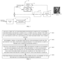
- FIG. 2 is a schematic block diagram of a video encoding system according to implementations.
- the video encoding system 200 includes a transform and quantization unit 201, an intra estimation unit 202, an intra prediction unit 203, a motion compensation unit 204, a motion estimation unit 205, an inverse transform and inverse quantization unit 206, a filter control analysis unit 207, a filtering unit 208, a coding unit 209, a decoded picture cache unit 210, and the like.
- the filtering unit 208 is configured to implement deblocking (DBK) filtering and sample adaptive offset (SAO) filtering.
- the coding unit 209 is configured to implement header information coding and context-based adaptive binary arithmatic coding (CABAC).
- CABAC header information coding and context-based adaptive binary arithmatic coding
- a video coding block may be obtained through division by a coding tree unit (CTU), and then residual sample information obtained through intra prediction or inter prediction is processed by the transform and quantization unit 201 to transform the video coding block, which includes transforming the residual information from a pixel domain to a transform domain. An obtained transform coefficient is quantized to further reduce bit rate.
- the intra estimation unit 202 and the intra prediction unit 203 are configured to perform intra prediction on the video coding block.
- the intra estimation unit 202 and the intra prediction unit 203 are configured to determine an intra prediction mode to be used for encoding the video coding block.
- the motion compensation unit 204 and the motion estimation unit 205 are configured to execute intra prediction coding on the received video coding block relative to one or more blocks in one or more reference pictures to provide time prediction information.
- Motion estimation executed by the motion estimation unit 205 is a process of generating a motion vector, where the motion vector can be used for estimating a motion of the video coding block, and then the motion compensation unit 204 is configured to execute motion compensation according to the motion vector determined by the motion estimation unit 205.
- the intra prediction unit 203 is further configured to provide selected intra prediction data to the coding unit 209, and the motion estimation unit 205 is configured to send to the coding unit 209 motion vector data calculated.
- the inverse transform and inverse quantization unit 206 is configured to reconstruct the video coding block.
- a residual block is reconstructed in the pixel domain, a blocking artifact in the reconstructed residual block is removed by the filter control analysis unit 207 and the filtering unit 208, and then the reconstructed residual block is added to a predictive block in a picture in the decoded picture cache unit 210 to generate a reconstructed video coding block.
- the coding unit 209 is configured to encode various coding parameters and quantized transform coefficients. In a CABAC-based coding algorithm, context contents may be based on neighbouring coding blocks and may be used for encoding information indicative of the determined intra prediction mode to output a bitstream of the video signal.
- the decoded picture cache unit 210 is configured to store the reconstructed video coding block as a prediction reference. As a video picture is encoded, new reconstructed video coding blocks are continuously generated, and these reconstructed video coding blocks will be stored in the decoded picture cache unit 210.
- FIG. 3 is a schematic block diagram of a video decoding system according to implementations.
- the video decoding system 300 includes a decoding unit 301, an inverse transform and inverse quantization unit 302, an intra prediction unit 303, a motion compensation unit 304, a filtering unit 305, a decoded picture cache unit 306, and the like.
- the decoding unit 301 can be configured to implement header information decoding and CABAC decoding.
- the filtering unit 305 can be configured to implement DBK filtering and SAO filtering. After an input video signal is encoded (illustrated in FIG. 2 ), a bitstream of the video signal is outputted.
- the bitstream is input into the video decoding system 300 and is first processed by the decoding unit 301 to obtain a decoded transform coefficient.
- the transform coefficient is processed by the inverse transform and inverse quantization unit 302, such that a residual block is generated in a pixel domain.
- the intra prediction unit 303 may be configured to generate prediction data of a current video coding block based on a determined intra prediction mode and data of a previous decoded block coming from a current frame or picture.
- the motion compensation unit 304 is configured to analyze a motion vector and other associated syntax elements to determine prediction information used for the video coding block and configured to use the prediction information to generate a predictive block of the video coding block that is currently being decoded.
- a residual block from the inverse transform and inverse quantization unit 302 and the corresponding predictive block generated by the intra prediction unit 303 or the motion compensation unit 304 are summed to form a decoded video block.
- a blocking artifact in the decoded video signal may be removed by the filtering unit 305 to improve video quality.
- the decoded video block is stored in the decoded picture cache unit 306.
- the decoded picture cache unit 306 is configured to store a reference picture used for subsequent intra prediction or motion compensation and also configured to output a video signal, that is, a restored original video signal is obtained.
- Implementations herein can be applied to the intra prediction unit 203 illustrated in FIG. 2 and the intra prediction unit illustrated in FIG. 303. In other words, implementations herein are applicable to both an encoding system and a decoding system, the disclosure is not limited in this regard.
- FIG. 4 is a schematic flowchart of a prediction decoding method according to implementations. The method includes the following.
- a first set of neighbouring reference samples is obtained by acquiring neighbouring reference samples of a coding block, where the first set of neighbouring reference samples includes reference samples in a reference row or a reference column neighbouring the coding block.
- positions corresponding to K reference samples are determined from a starting position of the reference row or the reference column, where K is a positive integer.
- a second set of neighbouring reference samples is obtained according to the determined positions corresponding to the K reference samples, where the second set of neighbouring reference samples includes neighbouring reference samples in the first set of neighbouring reference samples except the K reference samples.
- prediction decoding is performed on the coding block based on the second set of neighbouring reference samples.
- the coding block is a coding block to be subjected to prediction of a first colour component, prediction of a second colour component, or prediction of a third colour component.
- the reference row or the reference column neighbouring the coding block may refer to a reference row neighbouring a top side of the coding block, or a reference column neighbouring a left side of the coding block, and may also refer to a reference row or a reference column neighbouring any other side of the coding block, which is not limited herein.
- the following will describe in detail the reference row neighbouring the top side of the coding block as an example of the reference row, and describe in detail the reference column neighbouring the left side of the coding block as an example of the reference column.
- the reference samples in the reference row neighbouring the coding block may include reference samples neighbouring a top side and reference samples neighbouring a right top side (also referred to as neighbouring reference samples corresponding to the top side and neighbouring reference samples corresponding to the right top side respectively).
- the top side refers to the top side of the coding block.
- the right top side refers to a side which is obtained by extending the top side of the coding block horizontally to the right and has a length equal to the width of a current coding block.
- the reference samples in the reference column neighbouring the coding block may include reference samples neighbouring a left side and reference samples neighbouring a bottom left side (also referred to as neighbouring reference samples corresponding to the left side and neighbouring reference samples corresponding to the bottom left side respectively).
- the left side refers to the left side of the coding block.
- the bottom left side refers to a side which is obtained by extending the left side of the coding block vertically down and has a length equal to the height of the current coding block.
- the disclosure is not limited in this regard.
- the K reference samples refer to reference samples which are not that important and therefore can be skipped when obtaining the second set of neighbouring reference samples.
- the K reference samples are usually located near the starting position of the reference row or the reference column.
- the starting position of the reference row refers to a leftmost position of the reference row.
- the starting position of the reference column refers to a topmost position of the reference column. Since the reference row is in a horizontal direction, "the positions corresponding to the K reference samples are determined from the starting position of the reference row or the reference column" means that the positions corresponding to the K reference samples are determined from the leftmost position of the reference row horizontally to the right.
- the positions corresponding to the K reference samples are determined from the starting position of the reference row or the reference column
- the positions corresponding to the K reference samples are determined vertically down from the topmost position of the reference column.
- the first set of neighbouring reference samples is obtained by acquiring neighbouring reference samples of the coding block, where the first set of neighbouring reference samples includes reference samples in the reference row or the reference column neighbouring the coding block.
- the positions corresponding to the K reference samples are determined from the starting position of the reference row or the reference column, where K is a positive integer.
- the second set of neighbouring reference samples is obtained according to the determined positions corresponding to the K reference samples, where the second set of neighbouring reference samples includes neighbouring reference samples in the first set of neighbouring reference samples except the K reference samples.
- Prediction decoding is performed on the coding block according to the second set of neighbouring reference samples. Since the second set of neighbouring reference samples is obtained by skipping, in the first set of neighbouring reference samples, reference samples which are close to the starting position and therefore are not that important, a model parameter(s) constructed according to the second set of neighbouring reference samples is relatively accurate, which improves prediction decoding performance. In addition, the number of samples in the second set of neighbouring reference samples is small, which is possible to reduce search complexity, and on the other hand, improve compression efficiency of a video picture and thus decrease bit rate.
- the prediction decoding method provided herein is also applicable to a coding system.
- the second set of neighbouring reference samples in the coding system it is possible not only to improve prediction encoding performance of a video picture but also to improve encoding compression efficiency, thereby saving encoding code rate.
- the following will elaborate only construction of the second set of neighbouring reference samples in a decoding system as an example.
- a prediction mode of the coding block is an MDLM prediction mode, where the MDLM prediction mode includes an MDLM_A mode and an MDLM L mode.
- a value of K is calculated according to a length of the reference row and a first preset proportion, where the first preset proportion corresponds to the reference row, or in the MDLM_L mode, the value of K is calculated according to a length of the reference column and a second preset proportion, where the second preset proportion corresponds to the reference column.
- the following can be conducted before the positions corresponding to the K reference samples are determined from the starting position of the reference row or the reference column.
- the value of K is calculated according to a length of the top side of the coding block and the first preset proportion, or in the MDLM_L mode, the value of K is calculated according to a length of the left side of the coding block and the second preset proportion.
- the positions corresponding to the K reference samples are determined from the starting position of the reference row or the reference column as follows. In the MDLM_A mode, positions corresponding to K consecutive reference samples are determined from the leftmost position of the reference row to the right, or in the MDLM_L mode, positions corresponding to K consecutive reference samples are determined down from the topmost position of the reference column.
- a set of neighbouring reference samples which is constructed for searching for a maximum neighbouring reference value of the first colour component and a minimum neighbouring reference value of the first colour component, is the second set of neighbouring reference samples rather than the first set of neighbouring reference samples, where the second set of neighbouring reference samples are obtained by skipping (that is, not considering) a preset number of (that is, K) consecutive reference samples from the starting position.
- K a preset number of consecutive reference samples from the starting position.
- the value of K which represents the number of reference samples, may be preset, for example, 1, 2, 4, or the like, or may be calculated according to the length of the reference row or the reference column neighbouring the coding block and a corresponding preset proportion (i.e. the first preset proportion or the second preset proportion), or may be calculated according to the side length of the coding block and the a corresponding preset proportion.
- the value of K may be set according to actual needs in practice and will not be limited herein.
- a preset proportion corresponding to the reference row neighbouring the coding block is represented by the first preset proportion.
- a preset proportion corresponding to the reference column neighbouring the coding block is represented by the second preset proportion.
- the first preset proportion and the second preset proportion may have the same value or have difference values, which is not limited herein.
- the side length of the coding block is N (in the MDLM_A mode, N is the width of the coding block, that is, the length of the top side; and in the MDLM_L mode, N is the height of the coding block, that is, the length of the left side).
- the value of K can be directly acquired according to table 1.
- Table 1 shows an example of the number of reference samples (K) when constructing the second set of neighbouring reference samples in the MDLM mode.
- N 1 represents the number of neighbouring reference samples in the first set of neighbouring reference samples
- N 2 represents the number of neighbouring reference samples in the second set of neighbouring reference samples
- K represents a preset number of neighbouring reference samples that are skipped.
- the second set of neighbouring reference samples can be obtained in the following two manners.
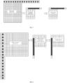
- FIG. 5 is a schematic diagram illustrating selection of neighbouring reference samples in the MDLM_A mode according to implementations.
- the coding block is in a square shape, and gray closed circles represent selected neighbouring reference samples of the coding block.
- Down-sampling needs to be performed on the first colour component, and as such, the first colour component subjected to down-sampling has the same resolution as the second colour component. Supposing that the first preset proportion is 1/4, and the length of the reference row (that is, the total number of reference samples neighbouring the top side and the right top side) is 16, the value of K is 4.
- positions of 4 consecutive reference samples are determined from the leftmost position of the reference row to the right, and the 4 reference samples are skipped.
- the remaining 3/4 of reference samples that is, 12 reference samples, which are close to the rightmost position, constitute the second set of neighbouring reference samples used for deriving model parameters ⁇ and ⁇ .
- the first preset proportion may be 1/8 or 1/2. Different first preset proportions correspond to different values of K, and the disclosure is not limited in this regard.
- Model parameter ⁇ is set to be 0, and model parameter ⁇ is set to be an intermediate value of the second colour component, that is, 512. In other words, a prediction value of the second colour component corresponding to each sample in the current coding block is 512.
- Exception 2 The neighbouring samples corresponding to the top side of the coding block are available, but neighbouring samples corresponding to a right top side of the coding block are not available.
- the length of the reference row (the number of reference samples neighbouring the top side only) is 8, the first preset proportion is 1/4, and the value of K is 2.
- the remaining 3/4 of reference samples (that is, 6 reference samples), which are close to the rightmost position, constitute the second set of neighbouring reference samples used for deriving model parameters ⁇ and ⁇ .
- the length of the top side (that is, the number of reference samples neighbouring the top side) is 8, the first preset proportion is 1/2, and the value of K is 4.
- the remaining 1/2 of reference samples (that is, 4 reference samples), which are close to the rightmost position, constitute the second set of neighbouring reference samples used for deriving model parameters ⁇ and ⁇ .
- the second set of neighbouring reference samples can be obtained in the following two manners.
- FIG. 6 is a schematic diagram illustrating selection of neighbouring reference samples in the MDLM_L mode according to implementations.
- the coding block is in a square shape, and gray closed circles represent selected neighbouring reference samples of the coding block.
- Down-sampling needs to be performed on the first colour component, and as such, the first colour component subjected to down-sampling has the same resolution as the second colour component. Supposing that the second preset proportion is 1/4, the length of the reference column (that is, the total number of reference samples neighbouring the left side and the bottom left side) is 16, the value of K is 4.
- positions of 4 consecutive reference samples are determined down from the topmost position of the reference column, and the 4 reference samples are skipped.
- the remaining 3/4 of reference samples that is, 12 reference samples, which are close to the bottommost position, constitute the second set of neighbouring reference samples used for deriving model parameters ⁇ and ⁇ .
- the second preset proportion may be 1/8 or 1/2. Different second preset proportions correspond to different values of K, and the disclosure is not limited in this regard.
- Model parameter ⁇ is set to be 0, and model parameter ⁇ is set to be an intermediate value of the second colour component, that is, 512. In other words, a prediction value of the second colour component corresponding to each sample in the current coding block is 512.
- Exception 2 The neighbouring samples corresponding to the left side of the coding block are available, but neighbouring samples corresponding to a bottom left side of the coding block are not available.
- the length of the reference column that is, the number of reference samples neighbouring the left side only
- the second preset proportion is 1/4
- the value of K is 2.
- the remaining 3/4 of reference samples that is, 6 reference samples
- the remaining 3/4 of reference samples which are close to the bottommost position, constitute the second set of neighbouring reference samples used for deriving model parameters ⁇ and ⁇ .
- the length of the left side (that is, the number of reference samples neighbouring the left side) is 8, the second preset proportion is 1/2, and the value of K is 4.
- the remaining 1/2 of reference samples (that is, 4 reference samples), which are close to the bottommost position, constitute the second set of neighbouring reference samples used for deriving model parameters ⁇ and ⁇ .
- the second set of neighbouring reference samples includes only reference samples corresponding to middle positions of the reference row or the reference column (that is, positions not close to the starting position and those close to the ending position).
- the value of i may be equal or unequal to that of j.
- the value of p may be equal or unequal to that of q. In practice, the value of i, the value of j, the value of p, and the value of q may be determined according to actual needs, and the disclosure is not limited in this regard.
- FIG. 7 is a schematic diagram illustrating selection of neighbouring reference samples in the MDLM_A mode according to other implementations.
- the coding block is in a square shape, and gray closed circles represent selected neighbouring reference samples of the coding block.
- Down-sampling needs to be performed on the first colour component, and as such, the first colour component subjected to down-sampling has the same resolution as the second colour component. Supposing that the first preset proportion is 1/4, and the length of the reference row (that is, the total number of reference samples neighbouring the top side and the right top side) is 16, the value of K is 4.
- FIG. 8 is a schematic diagram illustrating selection of neighbouring reference samples in an MDLM_L mode according to other implementations.
- the coding block is in a square shape, and gray closed circles represent selected neighbouring reference samples of the coding block.
- Down-sampling needs to be performed on the first colour component, and as such, the first colour component subjected to down-sampling has the same resolution as the second colour component. Supposing that the second preset proportion is 1/4, the length of the reference column (that is, the total number of reference samples neighbouring the left side and the bottom left side) is 16, the value of K is 4.
- a CCLM prediction mode is adopted in VTM.
- the second colour component can be obtained by predicting a reconstructed value of the first colour component of the coding block.
- i, j represent a position coordinate of a sample in the coding block, where i represents a horizontal direction, and j represents a vertical direction.
- Pre d c [ i, j ] represents a prediction value of the second colour component corresponding to a sample at position [ i, j ] in the coding block.
- Rec L [ i, j ] represents a reconstructed value of the first colour component corresponding to the sample at position [ i, j ] of the coding block subjected to down-sampling.
- ⁇ and ⁇ are model parameters of the above prediction model.
- second model parameters ⁇ and ⁇ may be constructed in various manners.
- the second model parameters ⁇ and ⁇ may be constructed based on least squares regression, based on a maximum value and minimum value, or in other manners. The following will elaborate respectively construction of model parameters ⁇ and ⁇ based on least squares regression and based on the maximum value and minimum value.
- ⁇ and ⁇ may be derived according to a neighbouring reference value of the first colour component and a neighbouring reference value of the second colour component which correspond to a reference sample in the second set of neighbouring reference samples, by using least-squares regression error.
- L(n) represents a neighbouring reference value of the first colour component corresponding to a reference sample in the second set of neighbouring reference samples.
- C(n) represents a neighbouring reference value of the second colour component corresponding to the reference sample in the second set of neighbouring reference samples.
- N is the number of reference samples in the second set of neighbouring reference samples.
- model parameters ⁇ and ⁇ may also be derived based on the principle that two points determine one line.
- ⁇ and ⁇ may be derived according to the following equation (3).
- L max and L min represent respectively a maximum value and a minimum value, which are obtained by searching among neighbouring reference values of first colour components corresponding to reference samples in the second set of neighbouring reference samples.
- C max represents a neighbouring reference value of the second colour component corresponding to a reference sample at a position corresponding to L max
- C min represents a neighbouring reference value of the second colour component corresponding to a reference sample at a position corresponding to L min .
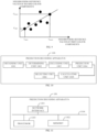
- FIG. 9 is a schematic structural diagram illustrating construction of a prediction model for the coding block based on a maximum value and minimum value according to implementations.
- the horizontal coordinate represents neighbouring reference values of first colour components corresponding to the coding block.
- the vertical coordinate represents neighbouring reference values of second colour components corresponding to the coding block.
- model parameters ⁇ and ⁇ can be calculated according to L max , L min , C max , and C min .
- prediction decoding is performed on the coding block according to the second set of neighbouring reference samples as follows.
- a first model parameter is determined according to the second set of neighbouring reference samples.
- a first prediction model is established according to the first model parameter, where the first prediction model is representative of a prediction relationship between a first colour component and a second colour component corresponding to each sample of the coding block.
- Prediction decoding is performed on the coding block according to the first prediction model.
- first model parameters ⁇ 1 and ⁇ 1 can be constructed according to equation (2) or equation (3).
- the first prediction model can be established according to equation (1).
- Prediction decoding can be performed on the coding block according to the first prediction model. Since the second set of neighbouring reference samples does not include reference samples which are close to the starting position and therefore are not that important, in addition to reducing search complexity, model parameters constructed according to reference samples of the second set of neighbouring reference samples can be more accurate, which can improve prediction decoding performance and on the other hand, improve compression efficiency of a video picture and thus decrease bit rate.
- reference samples may be further selected (or picked up) from the obtained second set of neighbouring reference samples at an equal interval or unequal intervals according to the sampling interval, to obtain a third set of neighbouring reference samples including the selected reference samples. Since the third set of neighbouring reference samples includes a smaller number of samples, search complexity can be further reduced.
- the method before prediction decoding is performed on the coding block according to the second set of neighbouring reference samples, the method further includes the following. Positions corresponding to reference samples to-be-selected are determined according to a preset number of samples, based on the second set of neighbouring reference samples. Based on the positions corresponding to reference samples to-be-selected, reference samples at these positions are selected from the second set of neighbouring reference samples, to obtain the third set of neighbouring reference samples including the selected reference samples.
- prediction decoding is performed on the coding block according to the second set of neighbouring reference samples as follows.
- a second model parameter is determined according to the third set of neighbouring reference samples.
- a second prediction model is established according to the second model parameter, where the second prediction model is representative of a prediction relationship between a first colour component and a second colour component corresponding to each sample of the coding block.
- Prediction decoding is performed on the coding block according to the second prediction model.
- the preset number of samples refers to the number of reference samples that is set in advance according to actual needs.
- the reference samples to-be-selected may be obtained by performing uniform sampling at a preset sampling interval on reference samples of the second set of neighbouring reference samples, or by performing non-uniform sampling at different preset sampling intervals on reference samples of the second set of neighbouring reference samples, which is determined according to actual needs in practice and is not limited herein.
- the third set of neighbouring reference samples can be obtained by performing uniform sampling or non-uniform sampling on reference samples of the second set of neighbouring reference samples.
- second model parameters ⁇ 2 and ⁇ 2 can be constructed based on the third set of neighbouring reference samples according to equation (2) or equation (3), and then the second prediction model can be established according to equation (1).
- Prediction decoding can be performed on the coding block according to the second prediction model.
- the third set of neighbouring reference samples not only reference samples which are close to the starting position and are not that important have been skipped, but also importance and dispersity are taken into consideration, such that the third set of neighbouring reference samples includes a smaller number of samples, which further reduces search complexity.
- model parameters constructed according to reference samples of the second set of neighbouring reference samples are relatively accurate, which improves prediction decoding performance, thereby decreasing bit rate.
- the coding block may be a square coding block or a non-square coding block.
- implementations herein are applicable to both a square coding block and a non-square coding block, which is not limited herein.
- the first set of neighbouring reference samples is obtained by acquiring neighbouring reference samples of the coding block, where the first set of neighbouring reference samples includes reference samples in the reference row or the reference column neighbouring the coding block.
- the positions corresponding to the K reference samples are determined from the starting position of the reference row or the reference column, where K is a positive integer.
- the second set of neighbouring reference samples is obtained according to the determined positions corresponding to the K reference samples, where the second set of neighbouring reference samples includes neighbouring reference samples in the first set of neighbouring reference samples except the K reference samples.
- Prediction decoding is performed on the coding block according to the second set of neighbouring reference samples.
- FIG. 10 is a schematic structural diagram of a prediction decoding apparatus 100 according to implementations.
- the prediction decoding apparatus 100 includes an obtaining unit 1001, a determining unit 1002, an excluding unit 1003, and a prediction unit 1004.
- the obtaining unit 1001 is configured to obtain a first set of neighbouring reference samples by acquiring neighbouring reference samples of a coding block, where the first set of neighbouring reference samples includes reference samples in a reference row or a reference column neighbouring the coding block.
- the determining unit 1002 is configured to determine, from a starting position of the reference row or the reference column, positions corresponding to K reference samples, where K is a positive integer.
- the excluding unit 1003 is configured to obtain a second set of neighbouring reference samples according to the determined positions corresponding to the K reference samples, where the second set of neighbouring reference samples includes neighbouring reference samples in the first set of neighbouring reference samples except the K reference samples.
- the prediction unit 1004 is configured to perform prediction decoding on the coding block according to the second set of neighbouring reference samples.
- a prediction mode of the coding block is an MDLM prediction mode, where the MDLM prediction mode includes an MDLM_A mode and an MDLM L mode.
- the prediction decoding apparatus 100 further includes a calculating unit 1005.
- the calculating unit 1005 is configured to, in the MDLM_A mode, calculate a value of K according to a length of the reference row and a first preset proportion, where the first preset proportion corresponds to the reference row, or in the MDLM_L mode, calculate the value of K according to a length of the reference column and a second preset proportion, where the second preset proportion corresponds to the reference column.
- the calculating unit is further configured to, in the MDLM_A mode, calculate the value of K according to a length of a top side of the coding block and the first preset proportion, or in the MDLM_L mode, calculate the value of K according to a length of a left side of the coding block and the second preset proportion.
- the determining unit 1002 is configured to, in the MDLM_A mode, determine, from a leftmost position of the reference row to the right, positions corresponding to K consecutive reference samples, or in the MDLM_L mode, determine, down from a topmost position of the reference column, positions corresponding to K consecutive reference samples.
- the determining unit 1002 is further configured to operate as follows in the MDLM_A mode.
- the determining unit 1002 is configured to determine, from a leftmost position of the reference row to the right, positions corresponding to i consecutive reference samples.
- the determining unit 1002 is further configured to operate as follows in the MDLM_L mode.
- the determining unit 1002 is configured to determine, down from a topmost position of the reference column, positions corresponding to p consecutive reference samples.
- the determining unit 1002 is further configured to determine a first model parameter according to the second set of neighbouring reference samples.
- the prediction unit 1004 is configured to operate as follows.
- the prediction unit 1004 is configured to establish a first prediction model according to the first model parameter, where the first prediction model is representative of a prediction relationship between a first colour component and a second colour component corresponding to each sample of the coding block.
- the prediction unit 1004 is configured to perform prediction decoding on the coding block according to the first prediction model.
- the prediction decoding apparatus 100 further includes a selecting unit 1006.
- the selecting unit 1006 is configured to operate as follows.
- the selecting unit 1006 is configured to determine, according to a preset number of samples, positions corresponding to reference samples to-be-selected, based on the second set of neighbouring reference samples.
- the selecting unit 1006 is configured to select, according to the positions corresponding to reference samples to-be-selected, reference samples corresponding to the positions from the second set of neighbouring reference samples, to obtain a third set of neighbouring reference samples including the selected reference samples.
- the determining unit 1002 is further configured to determine a second model parameter according to the third set of neighbouring reference samples.
- the prediction unit 1004 is configured to operate as follows.
- the prediction unit 1004 is configured to establish a second prediction model according to the second model parameter, where the second prediction model is representative of a prediction relationship between a first colour component and a second colour component corresponding to each sample of the coding block.
- the prediction unit 1004 is configured to perform prediction decoding on the coding block according to the second prediction model.
- unit may be part of a circuit, part of a processor, part of a program or software, and the like.
- Unit may be modular or non-modular.
- various components described herein may be integrated into one processing unit or may be present as a number of physically separated units, and two or more units may be integrated into one.
- the integrated unit may take the form of hardware or a software functional unit.
- the integrated units are implemented as software functional modules and sold or used as standalone products, they may be stored in a computer readable storage medium.
- the computer software products can be stored in a storage medium and may include multiple instructions that, when executed, can cause a computing device, e.g., a personal computer, a server, a network device, etc., or a processor to execute some or all operations of the methods described in various implementations.
- the above storage medium may include various kinds of media that can store program codes, such as a universal serial bus (USB) flash disk, a mobile hard drive, a read only memory (ROM), a random access memory (RAM), a magnetic disk, or an optical disk.
- USB universal serial bus
- ROM read only memory
- RAM random access memory
- implementations provide a computer storage medium.
- the computer storage medium is configured to store programs for prediction decoding which, when executed by at least one processor, are operable with the at least one processor to perform the foregoing method illustrated in FIG. 4 .
- FIG. 11 is a schematic structural diagram of hardware of a prediction decoding apparatus 100 according to implementations.
- the prediction decoding apparatus 100 includes a network interface 1101, a memory 1102, and a processor 1103.
- Various components are coupled together via a bus system 1104.
- the bus system 1104 is configured for connection and communication between these components.
- the bus system 1104 further includes a power bus, a control bus, and a status signal bus.
- various buses are marked as the bus system 1104 in FIG. 11 .
- the network interface 1101 is configured to receive and send a signal while receiving and sending information with other external network elements.
- the memory 1102 is configured to store computer programs executable by the processor 1103.
- the processor 1103, when running the computer programs, is configured to perform: obtaining a first set of neighbouring reference samples by acquiring neighbouring reference samples of a coding block, where the first set of neighbouring reference samples includes reference samples in a reference row or a reference column neighbouring the coding block; determining, from a starting position of the reference row or the reference column, positions corresponding to K reference samples, where K is a positive integer; obtaining a second set of neighbouring reference samples according to the determined positions corresponding to the K reference samples, where the second set of neighbouring reference samples includes neighbouring reference samples in the first set of neighbouring reference samples except the K reference samples; and performing prediction decoding on the coding block according to the second set of neighbouring reference samples.
- the memory 1102 of implementations may be a volatile memory or a non-volatile memory, or may include both the volatile memory and the non-volatile memory.
- the non-volatile memory may be a ROM, a programmable read only memory (programmable ROM, PROM), an erasable programmable read only memory (erasable PROM, EPROM), an electrically erasable programmable read only memory (electrically EPROM, EEPROM), or flash memory.
- the volatile memory can be a RAM that acts as an external cache.
- RAM random access memory
- static RAM static random access memory
- dynamic RAM dynamic random access memory
- DRAM dynamic random access memory
- SDRAM synchronous dynamic random access memory
- DDRSDRAM double data rate SDRAM
- ESDRAM enhanced synchronous dynamic random access memory
- SLDRAM synchronous link dynamic random access memory
- direct rambus RAM direct rambus RAM, DRRAM
- the memory 1102 of the systems and methods described herein is intended to include, but is not limited to, these and any other suitable types of memory.
- the processor 1103 may be an integrated circuit chip with signal processing capabilities. During implementation, each step of the foregoing method may be completed by an integrated logic circuit of hardware in the processor 1103 or an instruction in the form of software.
- the processor 1103 may be a general-purpose processor, a digital signal processor
- DSP digital signal processor
- ASIC application specific integrated circuit
- FPGA field programmable gate array
- the general-purpose processor may be a microprocessor, or the processor may be any conventional processor or the like.
- the steps of the method disclosed in implementations may be directly implemented as a hardware decoding processor, or may be performed by hardware and software modules in the decoding processor.
- the software module can be located in a storage medium such as a RAM, a flash memory, a ROM, a PROM, or an electrically erasable programmable memory, registers, and the like.
- the storage medium is located in the memory 1102.
- the processor 1103 reads the information in the memory 1102, and completes the steps of the method described above with the hardware thereof.
- implementations described herein can be implemented in one or more of hardware, software, firmware, middleware, and microcode.
- the processing unit can be implemented in one or more ASICs, DSPs, DSP devices (DSPD), programmable logic devices (PLD), FPGAs, general-purpose processors, controllers, microcontrollers, microprocessors, other electronic units for performing the functions described herein or a combination thereof.
- the technology described herein can be implemented by modules (e.g., procedures, functions, and so on) for performing the functions described herein.
- the software code can be stored in the memory and executed by the processor.
- the memory can be implemented in the processor or external to the processor.
- the processor 1103, when running the computer programs, is configured to perform the foregoing method described in FIG. 4 .
- Implementations provide a prediction decoding method.
- a first set of neighbouring reference samples is obtained by acquiring neighbouring reference samples of a coding block, where the first set of neighbouring reference samples includes reference samples in a reference row or a reference column neighbouring the coding block. Positions corresponding to K reference samples are determined from a starting position of the reference row or the reference column, where K is a positive integer.
- a second set of neighbouring reference samples is obtained according to the determined positions corresponding to the K reference samples, where the second set of neighbouring reference samples includes neighbouring reference samples in the first set of neighbouring reference samples except the K reference samples. Prediction decoding is performed on the coding block according to the second set of neighbouring reference samples.
- the second set of neighbouring reference samples is obtained by not considering, in the first set of neighbouring reference samples, reference samples which are close to the starting position and therefore are not that important, a model parameter(s) constructed according to the second set of neighbouring reference samples is relatively accurate, which improves prediction decoding performance.
- the number of samples in the second set of neighbouring reference samples is small, which is possible to reduce search complexity, and on the other hand, improve compression efficiency of a video picture and thus decrease bit rate.
Landscapes
- Engineering & Computer Science (AREA)
- Multimedia (AREA)
- Signal Processing (AREA)
- Compression Or Coding Systems Of Tv Signals (AREA)
- Compression, Expansion, Code Conversion, And Decoders (AREA)
- Compression Of Band Width Or Redundancy In Fax (AREA)
Abstract
Description
- This disclosure relates to the technical field of video encoding and decoding, and more particularly to a prediction decoding method, a prediction decoding apparatus, and a computer storage medium.
- With increase in people's requirements on video display quality, new video application forms such as high-definition video and ultra-high-definition video have emerged. H.265/high efficiency video coding (HEVC) is currently the latest international video compression standard. Although the compression performance of H.265/HEVC is higher than that of the previous-generation video encoding standard, H.264/advanced video coding (AVC), by about 50%, H.265/HEVC still fails to meet requirements for rapid development of video applications, especially new video applications such as ultra-high-definition video and virtual reality (VR).
- Video encoding experts group (VCEG) of international telegraph union telecommunication standardization sector (ITU-T) and moving picture experts group (MPEG) of international organization for standardization (ISO)/international electrotechnical commission (IEC) established joint video experts team (JVET) in 2015, to set a next-generation video encoding standard. In April 2018, JVET officially named the next-generation video encoding standard as versatile video coding (VVC), and its corresponding test model is VVC test model (VTM). A linear model-based prediction method has been integrated into VTM, and through such a linear model, a chroma component of a current coding block can be predicted according to a luma component thereof. However, when constructing a linear model, a set of neighbouring reference samples which is constructed by neighbouring reference samples is improper, which results in high search complexity and reduces prediction decoding performance of a video picture.
- To this end, implementations provide a prediction decoding method, a prediction decoding apparatus, and a computer storage medium. By decreasing the number of samples in a set of neighbouring reference samples, it is possible to reduce search complexity, improve prediction decoding performance of a video picture, and thus decrease bit rate.
- Technical solutions of implementations can be achieved as follows.
- In a first aspect, a prediction decoding method is provided. The method includes the following. A first set of neighbouring reference samples is obtained by acquiring neighbouring reference samples of a coding block, where the first set of neighbouring reference samples includes reference samples in a reference row or a reference column neighbouring the coding block. Positions corresponding to K reference samples are determined from a starting position of the reference row or the reference column, where K is a positive integer. A second set of neighbouring reference samples is obtained according to the determined positions corresponding to the K reference samples, where the second set of neighbouring reference samples includes neighbouring reference samples in the first set of neighbouring reference samples except the K reference samples. Prediction decoding is performed on the coding block according to the second set of neighbouring reference samples.
- In a second aspect, a prediction decoding apparatus is provided. The prediction decoding apparatus includes an obtaining unit, a determining unit, an excluding unit, and a prediction unit. The obtaining unit is configured to obtain a first set of neighbouring reference samples by acquiring neighbouring reference samples of a coding block, where the first set of neighbouring reference samples includes reference samples in a reference row or a reference column neighbouring the coding block. The determining unit is configured to determine, from a starting position of the reference row or the reference column, positions corresponding to K reference samples, where K is a positive integer. The excluding unit is configured to obtain a second set of neighbouring reference samples according to the determined positions corresponding to the K reference samples, where the second set of neighbouring reference samples includes neighbouring reference samples in the first set of neighbouring reference samples except the K reference samples. The prediction unit is configured to perform prediction decoding on the coding block according to the second set of neighbouring reference samples.
- In a third aspect, a prediction decoding apparatus is provided. The prediction decoding apparatus includes a memory and a processor. The memory is configured to store computer programs executable by the processor. The processor, when running the computer programs, is configured to perform the method described in the first aspect.
- In a fourth aspect, a computer storage medium is provided. The computer storage medium is configured to store programs for prediction decoding which, when executed by at least one processor, are operable with the at least one processor to perform the method described in the first aspect.
- Implementations provide a prediction decoding method, a prediction decoding apparatus, and a computer storage medium. According to the method provided herein, the first set of neighbouring reference samples is obtained by acquiring neighbouring reference samples of the coding block, where the first set of neighbouring reference samples includes reference samples in the reference row or the reference column neighbouring the coding block. The positions corresponding to the K reference samples are determined from the starting position of the reference row or the reference column, where K is a positive integer. The second set of neighbouring reference samples is obtained according to the determined positions corresponding to the K reference samples, where the second set of neighbouring reference samples includes neighbouring reference samples in the first set of neighbouring reference samples except the K reference samples. Prediction decoding is performed on the coding block according to the second set of neighbouring reference samples. Since the second set of neighbouring reference samples is obtained by skipping, in the first set of neighbouring reference samples, reference samples which are close to the starting position and therefore are not that important, a model parameter(s) constructed according to the second set of neighbouring reference samples is relatively accurate, which improves prediction decoding performance. In addition, the number of samples in the second set of neighbouring reference samples is small, which is possible to reduce search complexity, and on the other hand, improve compression efficiency of a video picture and thus decrease bit rate.
-
-
FIG. 1A to FIG. 1C are schematic diagrams of sampling formats of a video picture in the related art. -
FIG. 2 is a schematic block diagram of a video encoding system according to implementations. -
FIG. 3 is a schematic block diagram of a video decoding system according to implementations. -
FIG. 4 is a schematic flowchart of a prediction decoding method according to implementations. -
FIG. 5 is a schematic diagram illustrating selection of neighbouring reference samples in a multi-directional linear model_above (MDLM_A) mode according to implementations. -
FIG. 6 is a schematic diagram illustrating selection of neighbouring reference samples in an MDLM_Left (MDLM_L) mode according to implementations. -
FIG. 7 is a schematic diagram illustrating selection of neighbouring reference samples in an MDLM_A mode according to other implementations. -
FIG. 8 is a schematic diagram illustrating selection of neighbouring reference samples in an MDLM_L mode according to other implementations. -
FIG. 9 is a schematic structural diagram illustrating construction of a prediction model for a coding block based on a maximum value and minimum value according to implementations. -
FIG. 10 is a schematic structural diagram of a prediction decoding apparatus according to implementations. -
FIG. 11 is a schematic structural diagram of hardware of a prediction decoding apparatus according to implementations. - In order for more comprehensive understanding of features and technical solutions of implementations, the following will describe in detail implementations with reference to the accompanying drawings. The accompanying drawings are merely intended for illustration rather than limitation on the disclosure.
- In a video picture, a coding block is usually represented by a first colour component, a second colour component, and a third colour component. The above three colour components are respectively a luma component, a blue chroma component, and a red chroma component. The luma component is usually represented by symbol Y, the blue chroma component is usually represented by symbol Cb, and the red chroma component is usually represented by symbol Cr.
- According to implementations, the first colour component may be the luma component Y, the second colour component may be the blue chroma component Cb, and the third colour component may be the red chroma component Cr, but the disclosure is not limited in this regard. Currently, a commonly used sampling format is a YCbCr format. The YCbCr format includes the following types which are respectively illustrated in
FIG. 1A to FIG. 1C , where a cross (X) represents a sampling point of the first colour component, and a circle (∘) represents a sampling point of the second colour component or a sampling point of the third colour component. The YCbCr format includes the following types. - In a 4:4:4 format, as illustrated in
FIG. 1A , no down-sampling is performed on the second colour component or the third colour component. Every scan row contains four first colour components, four second colour components, and four third colour components sampled at every four consecutive samples. - In a 4:2:2 format, as illustrated in
FIG. 1B, 2:1 horizontal down-sampling is performed on the first colour component relative to the second colour component or the third colour component, with no vertical down-sampling performed. Every scan row contains four first colour components, two second colour components, and two third colour components sampled at every four consecutive samples. - In a 4:2:0 format, as illustrated in
FIG. 1C, 2:1 horizontal down-sampling and 2:1 vertical down-sampling are each performed on the first colour component relative to the second colour component or the third colour component. Every horizontal scan row and every vertical scan row each contain two first colour components, one second colour component, and one third colour component sampled at every two consecutive samples. - In case that the 4:2:0 format of the YCbCr format is adopted in a video picture, if the first colour component of the video picture is a coding block of size 2N×2N, the second colour component or the third colour component of the video picture is a coding block of size N×N, where N is the side length of the coding block. The following will elaborate the 4:2:0 format as an example, but technical solutions of implementations are also applicable to other sampling formats.
- In video encoding standard of H.266, in order to further improve encoding and decoding performance, cross-component prediction (CCP) has been extended, and cross-component linear model (CCLM) prediction and multi-directional linear model (MDLM) prediction have been proposed. In H.266, CCLM and MDLM both can achieve prediction between the first colour component and the second colour component, prediction between the first colour component and the third colour component, and prediction between the second colour component and the third colour component.
- Taking prediction between the first colour component and the second colour component as an example, in order to reduce redundancy between the first colour component and the second colour component, a CCLM prediction mode is used in a VTM, and the CCLM prediction mode may include a CCLM mode and a MDLM mode. Here, the CCLM mode is also referred to as a linear model (LM) mode. The MDLM mode may include an MDLM_Above (MDLM_A) mode and an MDLM Left (MDLM_L) mode, where the MDLM_A mode is also referred to as an MDLM Top (MDLM_T) mode or a CCLM_Top (CCLM_T) mode, and the MDLM_L mode is also referred to as a CCLM_Left (CCLM_L) mode. In general, in VTM 3.0 of VVC, the LM mode, the MDLM_A mode, and the MDLM_L mode are in a competitive relationship. The difference between the above three modes lies in that, the set of neighbouring reference samples, which is constructed for deriving model parameters α and β, is different.
- In order to make a set of neighbouring reference samples, which is constructed for deriving model parameters α and β, more accurate and thus improve prediction decoding performance, implementations provide a prediction decoding method. A first set of neighbouring reference samples is obtained by acquiring neighbouring reference samples of a coding block, where the first set of neighbouring reference samples includes reference samples in a reference row or a reference column neighbouring the coding block. Positions corresponding to K reference samples are determined from a starting position of the reference row or the reference column, where K is a positive integer. A second set of neighbouring reference samples is obtained according to the determined positions corresponding to the K reference samples, where the second set of neighbouring reference samples includes neighbouring reference samples in the first set of neighbouring reference samples except the K reference samples. Prediction decoding is performed on the coding block according to the second set of neighbouring reference samples. Since the second set of neighbouring reference samples is obtained by skipping, in the first set of neighbouring reference samples, reference samples which are close to the starting position and therefore are not that important, a model parameter(s) constructed according to the second set of neighbouring reference samples is relatively accurate, which improves prediction decoding performance. In addition, the number of samples in the second set of neighbouring reference samples is small, which is possible to reduce search complexity, and on the other hand, improve compression efficiency of a video picture and thus decrease bit rate. Implementations will be hereinafter described in detail with reference to the accompanying drawings.
-
FIG. 2 is a schematic block diagram of a video encoding system according to implementations. As illustrated inFIG. 2 , thevideo encoding system 200 includes a transform andquantization unit 201, anintra estimation unit 202, anintra prediction unit 203, amotion compensation unit 204, amotion estimation unit 205, an inverse transform andinverse quantization unit 206, a filtercontrol analysis unit 207, afiltering unit 208, a coding unit 209, a decodedpicture cache unit 210, and the like. Thefiltering unit 208 is configured to implement deblocking (DBK) filtering and sample adaptive offset (SAO) filtering. The coding unit 209 is configured to implement header information coding and context-based adaptive binary arithmatic coding (CABAC). For an input original video signal, a video coding block may be obtained through division by a coding tree unit (CTU), and then residual sample information obtained through intra prediction or inter prediction is processed by the transform andquantization unit 201 to transform the video coding block, which includes transforming the residual information from a pixel domain to a transform domain. An obtained transform coefficient is quantized to further reduce bit rate. Theintra estimation unit 202 and theintra prediction unit 203 are configured to perform intra prediction on the video coding block. Theintra estimation unit 202 and theintra prediction unit 203 are configured to determine an intra prediction mode to be used for encoding the video coding block. Themotion compensation unit 204 and themotion estimation unit 205 are configured to execute intra prediction coding on the received video coding block relative to one or more blocks in one or more reference pictures to provide time prediction information. Motion estimation executed by themotion estimation unit 205 is a process of generating a motion vector, where the motion vector can be used for estimating a motion of the video coding block, and then themotion compensation unit 204 is configured to execute motion compensation according to the motion vector determined by themotion estimation unit 205. After the intra prediction mode is determined, theintra prediction unit 203 is further configured to provide selected intra prediction data to the coding unit 209, and themotion estimation unit 205 is configured to send to the coding unit 209 motion vector data calculated. In addition, the inverse transform andinverse quantization unit 206 is configured to reconstruct the video coding block. A residual block is reconstructed in the pixel domain, a blocking artifact in the reconstructed residual block is removed by the filtercontrol analysis unit 207 and thefiltering unit 208, and then the reconstructed residual block is added to a predictive block in a picture in the decodedpicture cache unit 210 to generate a reconstructed video coding block. The coding unit 209 is configured to encode various coding parameters and quantized transform coefficients. In a CABAC-based coding algorithm, context contents may be based on neighbouring coding blocks and may be used for encoding information indicative of the determined intra prediction mode to output a bitstream of the video signal. The decodedpicture cache unit 210 is configured to store the reconstructed video coding block as a prediction reference. As a video picture is encoded, new reconstructed video coding blocks are continuously generated, and these reconstructed video coding blocks will be stored in the decodedpicture cache unit 210. -
FIG. 3 is a schematic block diagram of a video decoding system according to implementations. As illustrated inFIG. 3 , thevideo decoding system 300 includes adecoding unit 301, an inverse transform andinverse quantization unit 302, anintra prediction unit 303, amotion compensation unit 304, afiltering unit 305, a decodedpicture cache unit 306, and the like. Thedecoding unit 301 can be configured to implement header information decoding and CABAC decoding. Thefiltering unit 305 can be configured to implement DBK filtering and SAO filtering. After an input video signal is encoded (illustrated inFIG. 2 ), a bitstream of the video signal is outputted. The bitstream is input into thevideo decoding system 300 and is first processed by thedecoding unit 301 to obtain a decoded transform coefficient. The transform coefficient is processed by the inverse transform andinverse quantization unit 302, such that a residual block is generated in a pixel domain. Theintra prediction unit 303 may be configured to generate prediction data of a current video coding block based on a determined intra prediction mode and data of a previous decoded block coming from a current frame or picture. Themotion compensation unit 304 is configured to analyze a motion vector and other associated syntax elements to determine prediction information used for the video coding block and configured to use the prediction information to generate a predictive block of the video coding block that is currently being decoded. A residual block from the inverse transform andinverse quantization unit 302 and the corresponding predictive block generated by theintra prediction unit 303 or themotion compensation unit 304 are summed to form a decoded video block. A blocking artifact in the decoded video signal may be removed by thefiltering unit 305 to improve video quality. Then the decoded video block is stored in the decodedpicture cache unit 306. The decodedpicture cache unit 306 is configured to store a reference picture used for subsequent intra prediction or motion compensation and also configured to output a video signal, that is, a restored original video signal is obtained. - Implementations herein can be applied to the
intra prediction unit 203 illustrated inFIG. 2 and the intra prediction unit illustrated in FIG. 303. In other words, implementations herein are applicable to both an encoding system and a decoding system, the disclosure is not limited in this regard. - Based on the above examples of application scenarios illustrated in
FIG. 2 orFIG. 3, FIG. 4 is a schematic flowchart of a prediction decoding method according to implementations. The method includes the following. - At block S401, a first set of neighbouring reference samples is obtained by acquiring neighbouring reference samples of a coding block, where the first set of neighbouring reference samples includes reference samples in a reference row or a reference column neighbouring the coding block.
- At block S402, positions corresponding to K reference samples are determined from a starting position of the reference row or the reference column, where K is a positive integer.
- At block S403, a second set of neighbouring reference samples is obtained according to the determined positions corresponding to the K reference samples, where the second set of neighbouring reference samples includes neighbouring reference samples in the first set of neighbouring reference samples except the K reference samples.
- At block S404, prediction decoding is performed on the coding block based on the second set of neighbouring reference samples.
- The coding block is a coding block to be subjected to prediction of a first colour component, prediction of a second colour component, or prediction of a third colour component. The reference row or the reference column neighbouring the coding block may refer to a reference row neighbouring a top side of the coding block, or a reference column neighbouring a left side of the coding block, and may also refer to a reference row or a reference column neighbouring any other side of the coding block, which is not limited herein. For the convenience of description, the following will describe in detail the reference row neighbouring the top side of the coding block as an example of the reference row, and describe in detail the reference column neighbouring the left side of the coding block as an example of the reference column.
- The reference samples in the reference row neighbouring the coding block may include reference samples neighbouring a top side and reference samples neighbouring a right top side (also referred to as neighbouring reference samples corresponding to the top side and neighbouring reference samples corresponding to the right top side respectively). The top side refers to the top side of the coding block. The right top side refers to a side which is obtained by extending the top side of the coding block horizontally to the right and has a length equal to the width of a current coding block. The reference samples in the reference column neighbouring the coding block may include reference samples neighbouring a left side and reference samples neighbouring a bottom left side (also referred to as neighbouring reference samples corresponding to the left side and neighbouring reference samples corresponding to the bottom left side respectively). The left side refers to the left side of the coding block. The bottom left side refers to a side which is obtained by extending the left side of the coding block vertically down and has a length equal to the height of the current coding block. However, the disclosure is not limited in this regard.
- The K reference samples refer to reference samples which are not that important and therefore can be skipped when obtaining the second set of neighbouring reference samples. The K reference samples are usually located near the starting position of the reference row or the reference column. The starting position of the reference row refers to a leftmost position of the reference row. The starting position of the reference column refers to a topmost position of the reference column. Since the reference row is in a horizontal direction, "the positions corresponding to the K reference samples are determined from the starting position of the reference row or the reference column" means that the positions corresponding to the K reference samples are determined from the leftmost position of the reference row horizontally to the right. Since the reference column is in a vertical direction, "the positions corresponding to the K reference samples are determined from the starting position of the reference row or the reference column" means that the positions corresponding to the K reference samples are determined vertically down from the topmost position of the reference column. In this way, the first set of neighbouring reference samples is obtained by acquiring neighbouring reference samples of the coding block, where the first set of neighbouring reference samples includes reference samples in the reference row or the reference column neighbouring the coding block. The positions corresponding to the K reference samples are determined from the starting position of the reference row or the reference column, where K is a positive integer. The second set of neighbouring reference samples is obtained according to the determined positions corresponding to the K reference samples, where the second set of neighbouring reference samples includes neighbouring reference samples in the first set of neighbouring reference samples except the K reference samples. Prediction decoding is performed on the coding block according to the second set of neighbouring reference samples. Since the second set of neighbouring reference samples is obtained by skipping, in the first set of neighbouring reference samples, reference samples which are close to the starting position and therefore are not that important, a model parameter(s) constructed according to the second set of neighbouring reference samples is relatively accurate, which improves prediction decoding performance. In addition, the number of samples in the second set of neighbouring reference samples is small, which is possible to reduce search complexity, and on the other hand, improve compression efficiency of a video picture and thus decrease bit rate.
- It can be understood that, the prediction decoding method provided herein is also applicable to a coding system. By constructing the second set of neighbouring reference samples in the coding system, it is possible not only to improve prediction encoding performance of a video picture but also to improve encoding compression efficiency, thereby saving encoding code rate. The following will elaborate only construction of the second set of neighbouring reference samples in a decoding system as an example.
- In some implementations, a prediction mode of the coding block is an MDLM prediction mode, where the MDLM prediction mode includes an MDLM_A mode and an MDLM L mode.
- In some implementations, before the positions corresponding to the K reference samples are determined from the starting position of the reference row or the reference column, the following can be conducted. In the MDLM_A mode, a value of K is calculated according to a length of the reference row and a first preset proportion, where the first preset proportion corresponds to the reference row, or in the MDLM_L mode, the value of K is calculated according to a length of the reference column and a second preset proportion, where the second preset proportion corresponds to the reference column.
- In other implementations, before the positions corresponding to the K reference samples are determined from the starting position of the reference row or the reference column, the following can be conducted. In the MDLM_A mode, the value of K is calculated according to a length of the top side of the coding block and the first preset proportion, or in the MDLM_L mode, the value of K is calculated according to a length of the left side of the coding block and the second preset proportion.
- In some implementations, the positions corresponding to the K reference samples are determined from the starting position of the reference row or the reference column as follows. In the MDLM_A mode, positions corresponding to K consecutive reference samples are determined from the leftmost position of the reference row to the right, or in the MDLM_L mode, positions corresponding to K consecutive reference samples are determined down from the topmost position of the reference column.
- A set of neighbouring reference samples, which is constructed for searching for a maximum neighbouring reference value of the first colour component and a minimum neighbouring reference value of the first colour component, is the second set of neighbouring reference samples rather than the first set of neighbouring reference samples, where the second set of neighbouring reference samples are obtained by skipping (that is, not considering) a preset number of (that is, K) consecutive reference samples from the starting position. As such, reference samples close to the starting position which are not that important are excluded, such that a model parameter(s) constructed according to reference samples in the second set of neighbouring reference samples is relatively accurate, thereby improving prediction decoding performance.
- The value of K, which represents the number of reference samples, may be preset, for example, 1, 2, 4, or the like, or may be calculated according to the length of the reference row or the reference column neighbouring the coding block and a corresponding preset proportion (i.e. the first preset proportion or the second preset proportion), or may be calculated according to the side length of the coding block and the a corresponding preset proportion. However, the value of K may be set according to actual needs in practice and will not be limited herein. A preset proportion corresponding to the reference row neighbouring the coding block is represented by the first preset proportion. A preset proportion corresponding to the reference column neighbouring the coding block is represented by the second preset proportion. The first preset proportion and the second preset proportion may have the same value or have difference values, which is not limited herein.
- It can be understood that, for the MDLM_A mode applied to all reference samples in the reference row (that is, all neighbouring reference samples corresponding to the top side and the right top side) or the MDLM_L mode applied to all reference samples in the reference column (that is, all neighbouring reference samples corresponding to the left side and the bottom left side), the side length of the coding block is N (in the MDLM_A mode, N is the width of the coding block, that is, the length of the top side; and in the MDLM_L mode, N is the height of the coding block, that is, the length of the left side). For blocks to-be-decoded of different side lengths, the value of K can be directly acquired according to table 1. Table 1 shows an example of the number of reference samples (K) when constructing the second set of neighbouring reference samples in the MDLM mode. In table 1, N1 represents the number of neighbouring reference samples in the first set of neighbouring reference samples, N2 represents the number of neighbouring reference samples in the second set of neighbouring reference samples, and K represents a preset number of neighbouring reference samples that are skipped.
Table 1 Side length N N1 N2 K 2 4 3 1 4 8 6 2 8 16 12 4 16 32 24 8 32 64 48 16 - In the MDLM A mode, when all reference samples in the reference row (that is, all neighbouring reference samples corresponding to the top side and all neighbouring reference samples corresponding to the right top side) are available, the second set of neighbouring reference samples can be obtained in the following two manners.
- Manner 1: Taking the length of the reference row and the first preset proportion as an example, supposing that the first preset proportion is 1/4, the side length of the coding block (that is, the number of reference samples neighbouring the top side) is 8, and the length of the reference row (that is, the total number of reference samples neighbouring the top side and the right top side) is 16, the value of K is 4. In other words, in a set of neighbouring reference samples corresponding to the top side and the right top side, the remaining 3/4 of reference samples (that is, 12 reference samples), which are close to a rightmost position, constitute the second set of neighbouring reference samples used for deriving model parameters α and β.
- Manner 2: Taking the length of the top side of the coding block and the first preset proportion as an example, supposing that the first preset proportion is 1/2, the length of the top side of the coding block (that is, the number of reference samples neighbouring the top side) is 8, the value of K is 4. In other words, in a set of neighbouring reference samples corresponding to the top side and the right top side, the remaining 3/4 of reference samples (that is, 12 reference samples), which are close to the rightmost position, constitute the second set of neighbouring reference samples used for deriving model parameters α and β.
- As an example,
FIG. 5 is a schematic diagram illustrating selection of neighbouring reference samples in the MDLM_A mode according to implementations. As illustrated inFIG. 5 , the coding block is in a square shape, and gray closed circles represent selected neighbouring reference samples of the coding block. Down-sampling needs to be performed on the first colour component, and as such, the first colour component subjected to down-sampling has the same resolution as the second colour component. Supposing that the first preset proportion is 1/4, and the length of the reference row (that is, the total number of reference samples neighbouring the top side and the right top side) is 16, the value of K is 4. In other words, for each of the first colour component and the second colour component, positions of 4 consecutive reference samples are determined from the leftmost position of the reference row to the right, and the 4 reference samples are skipped. The remaining 3/4 of reference samples (that is, 12 reference samples), which are close to the rightmost position, constitute the second set of neighbouring reference samples used for deriving model parameters α and β. - Alternatively, the first preset proportion may be 1/8 or 1/2. Different first preset proportions correspond to different values of K, and the disclosure is not limited in this regard.
- In the MDLM_A mode, in addition to a general scenario in which all reference samples in the reference row (that is, all neighbouring reference samples corresponding to the top side and the right top side) are available, there are also some exceptions, and the following will describe in detail three exceptions.
- Exception 1: When neighbouring samples corresponding to a top side of the coding block are not available, there is no neighbouring reference sample. Model parameter α is set to be 0, and model parameter β is set to be an intermediate value of the second colour component, that is, 512. In other words, a prediction value of the second colour component corresponding to each sample in the current coding block is 512.
- Exception 2: The neighbouring samples corresponding to the top side of the coding block are available, but neighbouring samples corresponding to a right top side of the coding block are not available. For
manner 1 described above, the length of the reference row (the number of reference samples neighbouring the top side only) is 8, the first preset proportion is 1/4, and the value of K is 2. In other words, in a set of neighbouring reference samples corresponding to the top side of the coding block, the remaining 3/4 of reference samples (that is, 6 reference samples), which are close to the rightmost position, constitute the second set of neighbouring reference samples used for deriving model parameters α and β. For manner 2 described above, the length of the top side (that is, the number of reference samples neighbouring the top side) is 8, the first preset proportion is 1/2, and the value of K is 4. In other words, in a set of neighbouring reference samples corresponding to the top side of the coding block, the remaining 1/2 of reference samples (that is, 4 reference samples), which are close to the rightmost position, constitute the second set of neighbouring reference samples used for deriving model parameters α and β. - Exception 3: When all neighbouring samples corresponding to the top side of the coding block and all neighbouring samples corresponding to the right top side of the coding block are available, the second set of neighbouring reference samples used for deriving model parameters α and β is constructed in
manner 1 or manner 2 described above. - In the MDLM_L mode, when all reference samples in the reference column (that is, all neighbouring reference samples corresponding to the left side and all neighbouring reference samples corresponding to the bottom left side) are available, the second set of neighbouring reference samples can be obtained in the following two manners.
- Manner 3: Taking the length of the reference column and the second preset proportion as an example, supposing that the second preset proportion is 1/4, the side length of the coding block (that is, the number of reference samples neighbouring the left side) is 8, and the length of the reference column (that is, the total number of reference samples neighbouring the left side and the bottom left side) is 16, the value of K is 4. In other words, in a set of neighbouring reference samples corresponding to the left side and the bottom left side, the remaining 3/4 of reference samples (that is, 12 reference samples), which are close to a bottommost position, constitute the second set of neighbouring reference samples used for deriving model parameters α and β.
- Manner 4: Taking the length of the left side of the coding block and the second preset proportion as an example, supposing that the second preset proportion is 1/2, the length of the left side of the coding block (that is, the number of reference samples neighbouring the left side) is 8, the value of K is 4. In other words, in a set of neighbouring reference samples corresponding to the left side and the bottom left side, the remaining 3/4 of reference samples (that is, 12 reference samples), which are close to the bottommost position, constitute the second set of neighbouring reference samples used for deriving model parameters α and β.
- As an example,
FIG. 6 is a schematic diagram illustrating selection of neighbouring reference samples in the MDLM_L mode according to implementations. As illustrated inFIG. 6 , the coding block is in a square shape, and gray closed circles represent selected neighbouring reference samples of the coding block. Down-sampling needs to be performed on the first colour component, and as such, the first colour component subjected to down-sampling has the same resolution as the second colour component. Supposing that the second preset proportion is 1/4, the length of the reference column (that is, the total number of reference samples neighbouring the left side and the bottom left side) is 16, the value of K is 4. In other words, for each of the first colour component and the second colour component, positions of 4 consecutive reference samples are determined down from the topmost position of the reference column, and the 4 reference samples are skipped. The remaining 3/4 of reference samples (that is, 12 reference samples), which are close to the bottommost position, constitute the second set of neighbouring reference samples used for deriving model parameters α and β. - Alternatively, the second preset proportion may be 1/8 or 1/2. Different second preset proportions correspond to different values of K, and the disclosure is not limited in this regard.
- In the MDLM L mode, in addition to a general scenario in which all reference samples in the reference column (that is, all neighbouring reference samples corresponding to the left side and the bottom left side) are available, there are also some exceptions, and the following will describe in detail three exceptions.
- Exception 1: When neighbouring samples corresponding to a left side of the coding block are not available, there is no neighbouring reference sample. Model parameter α is set to be 0, and model parameter β is set to be an intermediate value of the second colour component, that is, 512. In other words, a prediction value of the second colour component corresponding to each sample in the current coding block is 512.
- Exception 2: The neighbouring samples corresponding to the left side of the coding block are available, but neighbouring samples corresponding to a bottom left side of the coding block are not available. For manner 3 described above, the length of the reference column (that is, the number of reference samples neighbouring the left side only) is 8, the second preset proportion is 1/4, and the value of K is 2. In other words, in a set of neighbouring reference samples corresponding to the left side, the remaining 3/4 of reference samples (that is, 6 reference samples), which are close to the bottommost position, constitute the second set of neighbouring reference samples used for deriving model parameters α and β. For manner 4 described above, the length of the left side (that is, the number of reference samples neighbouring the left side) is 8, the second preset proportion is 1/2, and the value of K is 4. In other words, in a set of neighbouring reference samples corresponding to the left side, the remaining 1/2 of reference samples (that is, 4 reference samples), which are close to the bottommost position, constitute the second set of neighbouring reference samples used for deriving model parameters α and β.
- Exception 3: When all neighbouring samples corresponding to the left side of the coding block and all neighbouring samples corresponding to the bottom left side of the coding block are available, the second set of neighbouring reference samples used for deriving model parameters α and β is constructed in manner 3 or manner 4 described above.
- In some implementations, in the MDLM_A mode, before the positions corresponding to the K reference samples are determined, the method further includes the following. Positions corresponding to i consecutive reference samples are determined from a leftmost position of the reference row to the right. Positions corresponding to j consecutive reference samples are determined from a rightmost position of the reference row to the left, where 1≤i<K, and j=K-i.
- In other implementations, in the MDLM_L mode, before the positions corresponding to the K reference samples are determined, the method further includes the following. Positions corresponding to p consecutive reference samples are determined down from a topmost position of the reference column. Positions corresponding to q consecutive reference samples are determined up from a bottommost position of the reference column, where 1≤p<K, and q=K-p.
- For each of the MDLM_A mode and the MDLM_L mode, some reference samples which are close to the starting position and some reference samples which are close to an ending position of the reference row or the reference column can be excluded, and the second set of neighbouring reference samples includes only reference samples corresponding to middle positions of the reference row or the reference column (that is, positions not close to the starting position and those close to the ending position). The value of i may be equal or unequal to that of j. The value of p may be equal or unequal to that of q. In practice, the value of i, the value of j, the value of p, and the value of q may be determined according to actual needs, and the disclosure is not limited in this regard.
- Taking the MDLM_A mode as an example,
FIG. 7 is a schematic diagram illustrating selection of neighbouring reference samples in the MDLM_A mode according to other implementations. As illustrated inFIG. 7 , the coding block is in a square shape, and gray closed circles represent selected neighbouring reference samples of the coding block. Down-sampling needs to be performed on the first colour component, and as such, the first colour component subjected to down-sampling has the same resolution as the second colour component. Supposing that the first preset proportion is 1/4, and the length of the reference row (that is, the total number of reference samples neighbouring the top side and the right top side) is 16, the value of K is 4. Supposing that the number of samples to be skipped which are close to one end of the reference row is the same as the number of samples to be skipped which are close to the other end of the reference row, in other words, 1/8 of reference samples, which are close to the starting position of the reference row, and 1/8 of reference samples, which are close to the ending position of the reference row, are skipped, that is, i=j=2. Therefore, for each of the first colour component and the second colour component, positions corresponding to 2 consecutive reference samples are determined from the leftmost position of the reference row to the right, and positions corresponding to 2 consecutive reference samples are determined from the rightmost position of the reference row to the left. Then the 4 reference samples thus determined are skipped. The remaining 3/4 of reference samples (that is, 12 reference samples), which are located at middle positions of the reference row, constitute the second set of neighbouring reference samples used for deriving model parameters α and β. - Taking the MDLM_L mode as an example,
FIG. 8 is a schematic diagram illustrating selection of neighbouring reference samples in an MDLM_L mode according to other implementations. As illustrated inFIG. 8 , the coding block is in a square shape, and gray closed circles represent selected neighbouring reference samples of the coding block. Down-sampling needs to be performed on the first colour component, and as such, the first colour component subjected to down-sampling has the same resolution as the second colour component. Supposing that the second preset proportion is 1/4, the length of the reference column (that is, the total number of reference samples neighbouring the left side and the bottom left side) is 16, the value of K is 4. Supposing that the number of samples to be skipped which are close to one end of the reference column is the same as the number of samples to be skipped which are close to the other end of the reference column, in other words, 1/8 of reference samples, which are close to the starting position of the reference column, and 1/8 of reference samples, which are close to the ending position of the reference column, are skipped, that is, p=q =2. Therefore, foe each of the first colour component and the second colour component, positions corresponding to 2 consecutive reference samples are determined down from the topmost position of the reference column, and positions corresponding to 2 consecutive reference samples are determined up from the bottommost position of the reference column. Then the 4 reference samples thus determined are skipped. The remaining 3/4 of reference samples (that is, 12 reference samples), which are located at middle positions of the reference column, constitute the second set of neighbouring reference samples used for deriving model parameters α and β. - It can be understood that, in order to reduce redundancy between the first colour component and the second colour component, a CCLM prediction mode is adopted in VTM. For CCLM prediction modes such as an LM mode and an MDLM mode, the second colour component can be obtained by predicting a reconstructed value of the first colour component of the coding block. For example, a prediction model of equation (1) can be adopted.

- i, j represent a position coordinate of a sample in the coding block, where i represents a horizontal direction, and j represents a vertical direction. Predc [i, j] represents a prediction value of the second colour component corresponding to a sample at position [i, j] in the coding block. RecL [i, j] represents a reconstructed value of the first colour component corresponding to the sample at position [i, j] of the coding block subjected to down-sampling. α and β are model parameters of the above prediction model.
- Based on the obtained second set of neighbouring reference samples above, second model parameters α and β may be constructed in various manners. The second model parameters α and β may be constructed based on least squares regression, based on a maximum value and minimum value, or in other manners. The following will elaborate respectively construction of model parameters α and β based on least squares regression and based on the maximum value and minimum value.
- In VVC, α and β may be derived according to a neighbouring reference value of the first colour component and a neighbouring reference value of the second colour component which correspond to a reference sample in the second set of neighbouring reference samples, by using least-squares regression error. α and β may be derived according to the following equation (2).

- L(n) represents a neighbouring reference value of the first colour component corresponding to a reference sample in the second set of neighbouring reference samples. C(n) represents a neighbouring reference value of the second colour component corresponding to the reference sample in the second set of neighbouring reference samples. N is the number of reference samples in the second set of neighbouring reference samples.
- In VVC, by searching for a maximum neighbouring reference value of the first colour component and a minimum neighbouring reference value of the first colour component in the second set of neighbouring reference samples, model parameters α and β may also be derived based on the principle that two points determine one line. α and β may be derived according to the following equation (3).

- Lmax and Lmin represent respectively a maximum value and a minimum value, which are obtained by searching among neighbouring reference values of first colour components corresponding to reference samples in the second set of neighbouring reference samples. Cmax represents a neighbouring reference value of the second colour component corresponding to a reference sample at a position corresponding to Lmax, and Cmin represents a neighbouring reference value of the second colour component corresponding to a reference sample at a position corresponding to Lmin.
FIG. 9 is a schematic structural diagram illustrating construction of a prediction model for the coding block based on a maximum value and minimum value according to implementations. The horizontal coordinate represents neighbouring reference values of first colour components corresponding to the coding block. The vertical coordinate represents neighbouring reference values of second colour components corresponding to the coding block. Based on equation (3), model parameters α and β can be calculated according to Lmax, Lmin, Cmax, and Cmin. A prediction model is constructed as C=α*L+β, where L represents a reconstructed value of the first colour component corresponding to a sample in the coding block, and C represents a prediction value of the second colour component corresponding to the sample of the coding block. - In some implementations, prediction decoding is performed on the coding block according to the second set of neighbouring reference samples as follows. A first model parameter is determined according to the second set of neighbouring reference samples. A first prediction model is established according to the first model parameter, where the first prediction model is representative of a prediction relationship between a first colour component and a second colour component corresponding to each sample of the coding block. Prediction decoding is performed on the coding block according to the first prediction model.
- After the second set of neighbouring reference samples is obtained, first model parameters α1 and β1 can be constructed according to equation (2) or equation (3). As such, the first prediction model can be established according to equation (1). Prediction decoding can be performed on the coding block according to the first prediction model. Since the second set of neighbouring reference samples does not include reference samples which are close to the starting position and therefore are not that important, in addition to reducing search complexity, model parameters constructed according to reference samples of the second set of neighbouring reference samples can be more accurate, which can improve prediction decoding performance and on the other hand, improve compression efficiency of a video picture and thus decrease bit rate.
- Alternatively, reference samples may be further selected (or picked up) from the obtained second set of neighbouring reference samples at an equal interval or unequal intervals according to the sampling interval, to obtain a third set of neighbouring reference samples including the selected reference samples. Since the third set of neighbouring reference samples includes a smaller number of samples, search complexity can be further reduced.
- In some implementations, before prediction decoding is performed on the coding block according to the second set of neighbouring reference samples, the method further includes the following. Positions corresponding to reference samples to-be-selected are determined according to a preset number of samples, based on the second set of neighbouring reference samples. Based on the positions corresponding to reference samples to-be-selected, reference samples at these positions are selected from the second set of neighbouring reference samples, to obtain the third set of neighbouring reference samples including the selected reference samples.
- In some implementations, prediction decoding is performed on the coding block according to the second set of neighbouring reference samples as follows. A second model parameter is determined according to the third set of neighbouring reference samples. A second prediction model is established according to the second model parameter, where the second prediction model is representative of a prediction relationship between a first colour component and a second colour component corresponding to each sample of the coding block. Prediction decoding is performed on the coding block according to the second prediction model.
- The preset number of samples refers to the number of reference samples that is set in advance according to actual needs. The reference samples to-be-selected may be obtained by performing uniform sampling at a preset sampling interval on reference samples of the second set of neighbouring reference samples, or by performing non-uniform sampling at different preset sampling intervals on reference samples of the second set of neighbouring reference samples, which is determined according to actual needs in practice and is not limited herein.
- In this way, the third set of neighbouring reference samples can be obtained by performing uniform sampling or non-uniform sampling on reference samples of the second set of neighbouring reference samples. As such, second model parameters α2 and β2 can be constructed based on the third set of neighbouring reference samples according to equation (2) or equation (3), and then the second prediction model can be established according to equation (1). Prediction decoding can be performed on the coding block according to the second prediction model. For the third set of neighbouring reference samples, not only reference samples which are close to the starting position and are not that important have been skipped, but also importance and dispersity are taken into consideration, such that the third set of neighbouring reference samples includes a smaller number of samples, which further reduces search complexity. As such, model parameters constructed according to reference samples of the second set of neighbouring reference samples are relatively accurate, which improves prediction decoding performance, thereby decreasing bit rate.
- The coding block may be a square coding block or a non-square coding block. In other words, implementations herein are applicable to both a square coding block and a non-square coding block, which is not limited herein.
- According to the method provided herein, the first set of neighbouring reference samples is obtained by acquiring neighbouring reference samples of the coding block, where the first set of neighbouring reference samples includes reference samples in the reference row or the reference column neighbouring the coding block. The positions corresponding to the K reference samples are determined from the starting position of the reference row or the reference column, where K is a positive integer. The second set of neighbouring reference samples is obtained according to the determined positions corresponding to the K reference samples, where the second set of neighbouring reference samples includes neighbouring reference samples in the first set of neighbouring reference samples except the K reference samples. Prediction decoding is performed on the coding block according to the second set of neighbouring reference samples. By means of obtaining the second set of neighbouring reference samples to decrease the number of reference samples, it is possible to reduce search complexity, improve prediction decoding performance of a video picture, and thus decrease bit rate.
- Based on the conception of the foregoing technical solutions illustrated in
FIG. 4 ,FIG. 10 is a schematic structural diagram of aprediction decoding apparatus 100 according to implementations. Theprediction decoding apparatus 100 includes an obtainingunit 1001, a determiningunit 1002, an excludingunit 1003, and aprediction unit 1004. The obtainingunit 1001 is configured to obtain a first set of neighbouring reference samples by acquiring neighbouring reference samples of a coding block, where the first set of neighbouring reference samples includes reference samples in a reference row or a reference column neighbouring the coding block. The determiningunit 1002 is configured to determine, from a starting position of the reference row or the reference column, positions corresponding to K reference samples, where K is a positive integer. The excludingunit 1003 is configured to obtain a second set of neighbouring reference samples according to the determined positions corresponding to the K reference samples, where the second set of neighbouring reference samples includes neighbouring reference samples in the first set of neighbouring reference samples except the K reference samples. Theprediction unit 1004 is configured to perform prediction decoding on the coding block according to the second set of neighbouring reference samples. - In some implementations, a prediction mode of the coding block is an MDLM prediction mode, where the MDLM prediction mode includes an MDLM_A mode and an MDLM L mode.
- In some implementations, as illustrated in
FIG. 10 , theprediction decoding apparatus 100 further includes a calculatingunit 1005. The calculatingunit 1005 is configured to, in the MDLM_A mode, calculate a value of K according to a length of the reference row and a first preset proportion, where the first preset proportion corresponds to the reference row, or in the MDLM_L mode, calculate the value of K according to a length of the reference column and a second preset proportion, where the second preset proportion corresponds to the reference column. - In some implementations, the calculating unit is further configured to, in the MDLM_A mode, calculate the value of K according to a length of a top side of the coding block and the first preset proportion, or in the MDLM_L mode, calculate the value of K according to a length of a left side of the coding block and the second preset proportion.
- In some implementations, the determining
unit 1002 is configured to, in the MDLM_A mode, determine, from a leftmost position of the reference row to the right, positions corresponding to K consecutive reference samples, or in the MDLM_L mode, determine, down from a topmost position of the reference column, positions corresponding to K consecutive reference samples. - In some implementations, the determining
unit 1002 is further configured to operate as follows in the MDLM_A mode. The determiningunit 1002 is configured to determine, from a leftmost position of the reference row to the right, positions corresponding to i consecutive reference samples. The determiningunit 1002 is configured to determine, from a rightmost position of the reference row to the left, positions corresponding to j consecutive reference samples, where 1≤i<K, and j=K-i. - In other implementations, the determining
unit 1002 is further configured to operate as follows in the MDLM_L mode. The determiningunit 1002 is configured to determine, down from a topmost position of the reference column, positions corresponding to p consecutive reference samples. The determiningunit 1002 is configured to determine, up from a bottommost position of the reference column, positions corresponding to q consecutive reference samples, where 1≤p<K, and q=K-p. - In some implementations, the determining
unit 1002 is further configured to determine a first model parameter according to the second set of neighbouring reference samples. Theprediction unit 1004 is configured to operate as follows. Theprediction unit 1004 is configured to establish a first prediction model according to the first model parameter, where the first prediction model is representative of a prediction relationship between a first colour component and a second colour component corresponding to each sample of the coding block. Theprediction unit 1004 is configured to perform prediction decoding on the coding block according to the first prediction model. - In some implementations, as illustrated in
FIG. 10 , theprediction decoding apparatus 100 further includes a selectingunit 1006. The selectingunit 1006 is configured to operate as follows. The selectingunit 1006 is configured to determine, according to a preset number of samples, positions corresponding to reference samples to-be-selected, based on the second set of neighbouring reference samples. The selectingunit 1006 is configured to select, according to the positions corresponding to reference samples to-be-selected, reference samples corresponding to the positions from the second set of neighbouring reference samples, to obtain a third set of neighbouring reference samples including the selected reference samples. - In some implementations, the determining
unit 1002 is further configured to determine a second model parameter according to the third set of neighbouring reference samples. Theprediction unit 1004 is configured to operate as follows. Theprediction unit 1004 is configured to establish a second prediction model according to the second model parameter, where the second prediction model is representative of a prediction relationship between a first colour component and a second colour component corresponding to each sample of the coding block. Theprediction unit 1004 is configured to perform prediction decoding on the coding block according to the second prediction model. - It can be understood that, in implementations herein, "unit" may be part of a circuit, part of a processor, part of a program or software, and the like. "Unit" may be modular or non-modular. In addition, various components described herein may be integrated into one processing unit or may be present as a number of physically separated units, and two or more units may be integrated into one. The integrated unit may take the form of hardware or a software functional unit.
- If the integrated units are implemented as software functional modules and sold or used as standalone products, they may be stored in a computer readable storage medium. Based on such an understanding, the essential technical solution, or the portion that contributes to the prior art, or all or part of the technical solution of the disclosure may be embodied as software products. The computer software products can be stored in a storage medium and may include multiple instructions that, when executed, can cause a computing device, e.g., a personal computer, a server, a network device, etc., or a processor to execute some or all operations of the methods described in various implementations. The above storage medium may include various kinds of media that can store program codes, such as a universal serial bus (USB) flash disk, a mobile hard drive, a read only memory (ROM), a random access memory (RAM), a magnetic disk, or an optical disk.
- Therefore, implementations provide a computer storage medium. The computer storage medium is configured to store programs for prediction decoding which, when executed by at least one processor, are operable with the at least one processor to perform the foregoing method illustrated in
FIG. 4 . - Based on the
prediction decoding apparatus 100 and the computer storage medium described above,FIG. 11 is a schematic structural diagram of hardware of aprediction decoding apparatus 100 according to implementations. Theprediction decoding apparatus 100 includes anetwork interface 1101, amemory 1102, and aprocessor 1103. Various components are coupled together via abus system 1104. It can be understood that, thebus system 1104 is configured for connection and communication between these components. In addition to a data bus, thebus system 1104 further includes a power bus, a control bus, and a status signal bus. However, for the clarity of description, various buses are marked as thebus system 1104 inFIG. 11 . - The
network interface 1101 is configured to receive and send a signal while receiving and sending information with other external network elements. Thememory 1102 is configured to store computer programs executable by theprocessor 1103. Theprocessor 1103, when running the computer programs, is configured to perform: obtaining a first set of neighbouring reference samples by acquiring neighbouring reference samples of a coding block, where the first set of neighbouring reference samples includes reference samples in a reference row or a reference column neighbouring the coding block; determining, from a starting position of the reference row or the reference column, positions corresponding to K reference samples, where K is a positive integer; obtaining a second set of neighbouring reference samples according to the determined positions corresponding to the K reference samples, where the second set of neighbouring reference samples includes neighbouring reference samples in the first set of neighbouring reference samples except the K reference samples; and performing prediction decoding on the coding block according to the second set of neighbouring reference samples. - It can be understood that, the
memory 1102 of implementations may be a volatile memory or a non-volatile memory, or may include both the volatile memory and the non-volatile memory. The non-volatile memory may be a ROM, a programmable read only memory (programmable ROM, PROM), an erasable programmable read only memory (erasable PROM, EPROM), an electrically erasable programmable read only memory (electrically EPROM, EEPROM), or flash memory. The volatile memory can be a RAM that acts as an external cache. By way of example but not limitation, many forms of RAM are available, such as a static random access memory (static RAM, SRAM), a dynamic random access memory (dynamic RAM, DRAM), a synchronous dynamic random access memory (synchronous DRAM, SDRAM), a double data rate SDRAM (DDRSDRAM), an enhanced synchronous dynamic random access memory (ESDRAM), a synchronous link dynamic random access memory (synch-link DRAM, SLDRAM), and a direct rambus random access memory (direct rambus RAM, DRRAM). Thememory 1102 of the systems and methods described herein is intended to include, but is not limited to, these and any other suitable types of memory. - The
processor 1103 may be an integrated circuit chip with signal processing capabilities. During implementation, each step of the foregoing method may be completed by an integrated logic circuit of hardware in theprocessor 1103 or an instruction in the form of software. Theprocessor 1103 may be a general-purpose processor, a digital signal processor - (DSP), an application specific integrated circuit (ASIC), a field programmable gate array (FPGA), or other programmable logic devices, discrete gates or transistor logic devices, discrete hardware components. The methods, steps, and logic blocks disclosed in implementations can be implemented or executed. The general-purpose processor may be a microprocessor, or the processor may be any conventional processor or the like. The steps of the method disclosed in implementations may be directly implemented as a hardware decoding processor, or may be performed by hardware and software modules in the decoding processor. The software module can be located in a storage medium such as a RAM, a flash memory, a ROM, a PROM, or an electrically erasable programmable memory, registers, and the like. The storage medium is located in the
memory 1102. Theprocessor 1103 reads the information in thememory 1102, and completes the steps of the method described above with the hardware thereof. - It will be appreciated that implementations described herein can be implemented in one or more of hardware, software, firmware, middleware, and microcode. For hardware implementation, the processing unit can be implemented in one or more ASICs, DSPs, DSP devices (DSPD), programmable logic devices (PLD), FPGAs, general-purpose processors, controllers, microcontrollers, microprocessors, other electronic units for performing the functions described herein or a combination thereof.
- For a software implementation, the technology described herein can be implemented by modules (e.g., procedures, functions, and so on) for performing the functions described herein. The software code can be stored in the memory and executed by the processor. The memory can be implemented in the processor or external to the processor.
- The
processor 1103, when running the computer programs, is configured to perform the foregoing method described inFIG. 4 . - Technical solutions described in various implementations can be combined with each other without conflict.
- While the disclosure has been described in connection with certain embodiments, it is to be understood that the disclosure is not to be limited to the disclosed embodiments but, on the contrary, is intended to cover various modifications and equivalent arrangements included within the scope of the appended claims, which scope is to be accorded the broadest interpretation so as to encompass all such modifications and equivalent structures as is permitted under the law.
- The following numbered clauses, describing aspects of the disclosure, are part of the description.
- 1. A prediction decoding method, comprising:
- obtaining a first set of neighbouring reference samples by acquiring neighbouring reference samples of a coding block, wherein the first set of neighbouring reference samples comprises reference samples in a reference row or a reference column neighbouring the coding block;
- determining, from a starting position of the reference row or the reference column, positions corresponding to K reference samples, wherein K is a positive integer;
- obtaining a second set of neighbouring reference samples according to the determined positions corresponding to the K reference samples, wherein the second set of neighbouring reference samples comprises neighbouring reference samples in the first set of neighbouring reference samples except the K reference samples; and
- performing prediction decoding on the coding block according to the second set of neighbouring reference samples.
- 2. The method of
clause 1, wherein a prediction mode of the coding block is a multi-directional linear model (MDLM) prediction mode, wherein the MDLM prediction mode comprises an MDLM_A mode and an MDLM_L mode. - 3. The method of clause 2, further comprising one of:
before determining, from the starting position of the reference row or the reference column, the positions corresponding to the K reference samples,- in the MDLM_A mode, calculating a value of K according to a length of the reference row and a first preset proportion, wherein the first preset proportion corresponds to the reference row; and
- in the MDLM_L mode, calculating the value of K according to a length of the reference column and a second preset proportion, wherein the second preset proportion corresponds to the reference column.
- 4. The method of clause 2, further comprising one of:
before determining, from the starting position of the reference row or the reference column, the positions corresponding to the K reference samples,- in the MDLM_A mode, calculating a value of K according to a length of a top side of the coding block and a first preset proportion; and
- in the MDLM_L mode, calculating the value of K according to a length of a left side of the coding block and a second preset proportion.
- 5. The method of clause 3 or 4, wherein determining, from the starting position of the reference row or the reference column, the positions corresponding to the K reference samples comprises one of:
- in the MDLM_A mode, determining, from a leftmost position of the reference row to the right, positions corresponding to K consecutive reference samples; or
- in the MDLM_L mode, determining, down from a topmost position of the reference column, positions corresponding to K consecutive reference samples.
- 6. The method of clause 2, wherein in the MDLM_A mode, the method further comprises:
before determining the positions corresponding to the K reference samples,- determining, from a leftmost position of the reference row to the right, positions corresponding to i consecutive reference samples; and
- determining, from a rightmost position of the reference row to the left, positions corresponding to j consecutive reference samples, wherein i is a positive integer, wherein 1≤i<K, and j=K-i.
- 7. The method of clause 2, wherein in the MDLM_L mode, the method further comprises:
before determining the positions corresponding to the K reference samples,- determining, down from a topmost position of the reference column, positions corresponding to p consecutive reference samples; and
- determining, up from a bottommost position of the reference column, positions corresponding to q consecutive reference samples, wherein p is a positive integer, wherein 1≤p<K, and q=K-p.
- 8. The method of
clause 1, wherein performing prediction decoding on the coding block according to the second set of neighbouring reference samples comprises:- determining a first model parameter according to the second set of neighbouring reference samples;
- establishing a first prediction model according to the first model parameter, wherein the first prediction model represents a prediction relationship between a first colour component and a second colour component corresponding to each sample of the coding block; and
- performing prediction decoding on the coding block according to the first prediction model.
- 9. The method of
clause 1, further comprising:
before performing prediction decoding on the coding block according to the second set of neighbouring reference samples,- determining, according to a preset number of samples, positions corresponding to reference samples to-be-selected, based on the second set of neighbouring reference samples; and
- selecting, according to the positions corresponding to reference samples to-be-selected, reference samples corresponding to the positions from the second set of neighbouring reference samples, to obtain a third set of neighbouring reference samples comprising the selected reference samples.
- 10. The method of clause 9, wherein performing prediction decoding on the coding block according to the second set of neighbouring reference samples comprises:
- determining a second model parameter according to the third set of neighbouring reference samples;
- establishing a second prediction model according to the second model parameter, wherein the second prediction model is representative of a prediction relationship between a first colour component and a second colour component corresponding to each sample of the coding block; and
- performing prediction decoding on the coding block according to the second prediction model.
- 11. A prediction decoding apparatus, comprising:
- an obtaining unit configured to obtain a first set of neighbouring reference samples by acquiring neighbouring reference samples of a coding block, wherein the first set of neighbouring reference samples comprises reference samples in a reference row or a reference column neighbouring the coding block;
- a determining unit configured to determine, from a starting position of the reference row or the reference column, positions corresponding to K reference samples, wherein K is a positive integer;
- an excluding unit configured to obtain a second set of neighbouring reference samples according to the determined positions corresponding to the K reference samples, wherein the second set of neighbouring reference samples comprises neighbouring reference samples in the first set of neighbouring reference samples except the K reference samples; and
- a prediction unit configured to perform prediction decoding on the coding block according to the second set of neighbouring reference samples.
- 12. The apparatus of clause 11, wherein a prediction mode of the coding block is a multi-directional linear model (MDLM) prediction mode, wherein the MDLM prediction mode comprises an MDLM_A mode and an MDLM_L mode.
- 13. The apparatus of clause 12, further comprising:
a calculating unit configured to perform one of:- in the MDLM_A mode, calculating a value of K according to a length of the reference row and a first preset proportion, wherein the first preset proportion corresponds to the reference row; or
- in the MDLM_L mode, calculating the value of K according to a length of the reference column and a second preset proportion, wherein the second preset proportion corresponds to the reference column.
- 14. The apparatus of clause 13, wherein the calculating unit is further configured to perform one of:
- in the MDLM_A mode, calculating the value of K according to a length of a top side of the coding block and the first preset proportion; or
- in the MDLM_L mode, calculating the value of K according to a length of a left side of the coding block and the second preset proportion.
- 15. The apparatus of clause 13 or 14, wherein the determining unit is configured to perform one of:
- in the MDLM_A mode, determining, from a leftmost position of the reference row to the right, positions corresponding to K consecutive reference samples; or
- in the MDLM_L mode, determining, down from a topmost position of the reference column, positions corresponding to K consecutive reference samples.
- 16. The apparatus of clause 12, wherein in the MDLM_A mode, the determining unit is further configured to:
- determine, from a leftmost position of the reference row to the right, positions corresponding to i consecutive reference samples; and
- determine, from a rightmost position of the reference row to the left, positions corresponding to j consecutive reference samples, wherein i is a positive integer, wherein 1≤i<K, and j=K-i.
- 17. The apparatus of clause 12, wherein in the MDLM_L mode, the determining unit is further configured to:
- determine, down from a topmost position of the reference column, positions corresponding to p consecutive reference samples; and
- determine, up from a bottommost position of the reference column, positions corresponding to q consecutive reference samples, wherein p is a positive integer, wherein 1≤ p<K, and q=K-p.
- 18. The apparatus of clause 11, wherein
- the determining unit is further configured to:
determine a first model parameter according to the second set of neighbouring reference samples; and - the prediction unit is configured to:
- establish a first prediction model according to the first model parameter, wherein the first prediction model is representative of a prediction relationship between a first colour component and a second colour component corresponding to each sample of the coding block; and
- perform prediction decoding on the coding block according to the first prediction model.
- the determining unit is further configured to:
- 19. The apparatus of clause 11, further comprising:
a selecting unit configured to:- determine, according to a preset number of samples, positions corresponding to reference samples to-be-selected, based on the second set of neighbouring reference samples; and
- select, according to the positions corresponding to reference samples to-be-selected, reference samples corresponding to the positions from the second set of neighbouring reference samples, to obtain a third set of neighbouring reference samples comprising the selected reference samples.
- 20. The apparatus of clause 19, wherein
- the determining unit is further configured to:
determine a second model parameter according to the third set of neighbouring reference samples; and - the prediction unit is configured to:
- establish a second prediction model according to the second model parameter, wherein the second prediction model is representative of a prediction relationship between a first colour component and a second colour component corresponding to each sample of the coding block; and
- perform prediction decoding on the coding block according to the second prediction model.
- the determining unit is further configured to:
- 21. A prediction decoding apparatus, comprising:
- a memory configured to store computer programs executable by a processor; and
- the processor, when running the computer programs, configured to perform the method of any of
clauses 1 to 10.
- 22. A computer storage medium configured to store programs for prediction decoding which, when executed by at least one processor, are operable with the at least one processor to perform the method of any of
clauses 1 to 10. - Implementations provide a prediction decoding method. A first set of neighbouring reference samples is obtained by acquiring neighbouring reference samples of a coding block, where the first set of neighbouring reference samples includes reference samples in a reference row or a reference column neighbouring the coding block. Positions corresponding to K reference samples are determined from a starting position of the reference row or the reference column, where K is a positive integer. A second set of neighbouring reference samples is obtained according to the determined positions corresponding to the K reference samples, where the second set of neighbouring reference samples includes neighbouring reference samples in the first set of neighbouring reference samples except the K reference samples. Prediction decoding is performed on the coding block according to the second set of neighbouring reference samples. Since the second set of neighbouring reference samples is obtained by not considering, in the first set of neighbouring reference samples, reference samples which are close to the starting position and therefore are not that important, a model parameter(s) constructed according to the second set of neighbouring reference samples is relatively accurate, which improves prediction decoding performance. In addition, the number of samples in the second set of neighbouring reference samples is small, which is possible to reduce search complexity, and on the other hand, improve compression efficiency of a video picture and thus decrease bit rate.
Claims (12)
- A prediction decoding method, comprising:obtaining (S401) a first set of neighbouring reference samples by acquiring neighbouring reference samples of a coding block, wherein the first set of neighbouring reference samples comprises reference samples in a reference row or a reference column neighbouring the coding block;determining (S402), from a starting position of the reference row or the reference column, positions corresponding to K reference samples, wherein K is a positive integer;obtaining (S403) a second set of neighbouring reference samples according to the determined positions corresponding to the K reference samples, wherein the second set of neighbouring reference samples comprises neighbouring reference samples in the first set of neighbouring reference samples except the K reference samples; andperforming (S404) prediction decoding on the coding block according to the second set of neighbouring reference samples, whereina prediction mode of the coding block is a multi-directional linear model (MDLM) prediction mode, wherein the MDLM prediction mode comprises an MDLM_A mode and an MDLM_L mode; and whereinin the MDLM_A mode, a value of K is calculated according to a length of the reference row and a first preset proportion corresponding to the reference row; orin the MDLM_L mode, the value of K is calculated according to a length of the reference column and a second preset proportion corresponding to the reference column.
- The method of claim 1, wherein determining, from the starting position of the reference row or the reference column, the positions corresponding to the K reference samples comprises one of:in the MDLM_A mode, determining, from a leftmost position of the reference row to the right, positions corresponding to K consecutive reference samples; orin the MDLM_L mode, determining, down from a topmost position of the reference column, positions corresponding to K consecutive reference samples.
- The method of claim 1, wherein in the MDLM_A mode, the method further comprises:
before determining the positions corresponding to the K reference samples,determining, from a leftmost position of the reference row to the right, positions corresponding to i consecutive reference samples; anddetermining, from a rightmost position of the reference row to the left, positions corresponding to j consecutive reference samples, wherein i is a positive integer, wherein 1≤i<K, and j=K-i. - The method of claim 1, wherein in the MDLM_L mode, the method further comprises: before determining the positions corresponding to the K reference samples,determining, down from a topmost position of the reference column, positions corresponding to p consecutive reference samples; anddetermining, up from a bottommost position of the reference column, positions corresponding to q consecutive reference samples, wherein p is a positive integer, wherein 1≤p<K, and q=K-p.
- The method of claim 1, wherein performing prediction decoding on the coding block according to the second set of neighbouring reference samples comprises:determining a first model parameter according to the second set of neighbouring reference samples;establishing a first prediction model according to the first model parameter, wherein the first prediction model represents a prediction relationship between a first colour component and a second colour component corresponding to each sample of the coding block; andperforming prediction decoding on the coding block according to the first prediction model.
- The method of claim 1, further comprising:
before performing prediction decoding on the coding block according to the second set of neighbouring reference samples,determining, according to a preset number of samples, positions corresponding to reference samples to-be-selected, based on the second set of neighbouring reference samples; andselecting, according to the positions corresponding to reference samples to-be-selected, reference samples corresponding to the positions from the second set of neighbouring reference samples, to obtain a third set of neighbouring reference samples comprising the selected reference samples. - The method of claim 6, wherein performing prediction decoding on the coding block according to the second set of neighbouring reference samples comprises:determining a second model parameter according to the third set of neighbouring reference samples;establishing a second prediction model according to the second model parameter, wherein the second prediction model is representative of a prediction relationship between a first colour component and a second colour component corresponding to the coding block; andperforming prediction decoding on the coding block according to the second prediction model.
- The method of claim 6, wherein determining, according to a preset number of samples, positions corresponding to reference samples to-be-selected comprises:
determining the positions corresponding to reference samples to-be-selected in second set of neighbouring reference samples according to sampling intervals. - The method of claim 8, wherein the sampling intervals are equal sampling intervals, determining the positions corresponding to reference samples to-be-selected in second set of neighbouring reference samples according to sampling intervals comprises:
determining the positions corresponding to reference samples to-be-selected in second set of neighbouring reference samples by performing uniform sampling on the second set of neighbouring reference samples according to the equal sampling intervals. - The method of claim 8, wherein the sampling intervals are unequal sampling intervals, determining the positions corresponding to reference samples to-be-selected in second set of neighbouring reference samples according to sampling intervals comprises:
determining the positions corresponding to reference samples to-be-selected in second set of neighbouring reference samples by performing non-uniform sampling on the second set of neighbouring reference samples according to the unequal sampling intervals. - The method of claim 1, wherein each reference sample corresponds to a luma position, the neighbouring reference samples comprises above neighbouring samples and left neighbouring reference samples; and/or
wherein the second set of neighbouring reference samples starts from the (K+1)th reference sample among the first set of neighbouring reference samples. - A prediction decoding apparatus (100), comprising:a memory (1102) configured to store computer programs executable by a processor; andthe processor (1103), when running the computer programs, configured to perform the method of any of claims 1 to 11.
Priority Applications (1)
| Application Number | Priority Date | Filing Date | Title |
|---|---|---|---|
| EP24197591.1A EP4447436A3 (en) | 2019-01-02 | 2019-01-02 | Prediction decoding method and apparatus, and computer storage medium |
Applications Claiming Priority (3)
| Application Number | Priority Date | Filing Date | Title |
|---|---|---|---|
| EP19907160.6A EP3890323B1 (en) | 2019-01-02 | 2019-01-02 | Prediction decoding method, device and computer storage medium |
| EP24197591.1A EP4447436A3 (en) | 2019-01-02 | 2019-01-02 | Prediction decoding method and apparatus, and computer storage medium |
| PCT/CN2019/070147 WO2020140214A1 (en) | 2019-01-02 | 2019-01-02 | Prediction decoding method, device and computer storage medium |
Related Parent Applications (2)
| Application Number | Title | Priority Date | Filing Date |
|---|---|---|---|
| EP19907160.6A Division EP3890323B1 (en) | 2019-01-02 | 2019-01-02 | Prediction decoding method, device and computer storage medium |
| EP19907160.6A Division-Into EP3890323B1 (en) | 2019-01-02 | 2019-01-02 | Prediction decoding method, device and computer storage medium |
Publications (2)
| Publication Number | Publication Date |
|---|---|
| EP4447436A2 true EP4447436A2 (en) | 2024-10-16 |
| EP4447436A3 EP4447436A3 (en) | 2025-01-15 |
Family
ID=71406604
Family Applications (2)
| Application Number | Title | Priority Date | Filing Date |
|---|---|---|---|
| EP24197591.1A Pending EP4447436A3 (en) | 2019-01-02 | 2019-01-02 | Prediction decoding method and apparatus, and computer storage medium |
| EP19907160.6A Active EP3890323B1 (en) | 2019-01-02 | 2019-01-02 | Prediction decoding method, device and computer storage medium |
Family Applications After (1)
| Application Number | Title | Priority Date | Filing Date |
|---|---|---|---|
| EP19907160.6A Active EP3890323B1 (en) | 2019-01-02 | 2019-01-02 | Prediction decoding method, device and computer storage medium |
Country Status (8)
| Country | Link |
|---|---|
| US (6) | US11412244B2 (en) |
| EP (2) | EP4447436A3 (en) |
| JP (7) | JP7295959B2 (en) |
| KR (3) | KR102811925B1 (en) |
| CN (7) | CN113395520B (en) |
| AU (5) | AU2019417996B2 (en) |
| MX (5) | MX2021008080A (en) |
| WO (1) | WO2020140214A1 (en) |
Families Citing this family (1)
| Publication number | Priority date | Publication date | Assignee | Title |
|---|---|---|---|---|
| CN113395520B (en) * | 2019-01-02 | 2023-05-16 | Oppo广东移动通信有限公司 | Decoding prediction method, device and computer storage medium |
Family Cites Families (46)
| Publication number | Priority date | Publication date | Assignee | Title |
|---|---|---|---|---|
| WO2009080132A1 (en) * | 2007-12-21 | 2009-07-02 | Telefonaktiebolaget L M Ericsson (Publ) | Improved pixel prediction for video coding |
| US9736486B2 (en) * | 2010-02-08 | 2017-08-15 | Nokia Technologies Oy | Apparatus, a method and a computer program for video coding |
| KR20110125153A (en) * | 2010-05-12 | 2011-11-18 | 에스케이 텔레콤주식회사 | Image filtering method and apparatus and method and apparatus for encoding / decoding using the same |
| US9258573B2 (en) * | 2010-12-07 | 2016-02-09 | Panasonic Intellectual Property Corporation Of America | Pixel adaptive intra smoothing |
| MY173195A (en) | 2011-06-28 | 2020-01-03 | Samsung Electronics Co Ltd | Method and apparatus for image encoding and decoding using intra prediction |
| JP5711098B2 (en) * | 2011-11-07 | 2015-04-30 | 日本電信電話株式会社 | Image encoding method, image decoding method, image encoding device, image decoding device, and programs thereof |
| EP2805496B1 (en) * | 2012-01-19 | 2016-12-21 | Huawei Technologies Co., Ltd. | Reference pixel reduction for intra lm prediction |
| GB2498550B (en) | 2012-01-19 | 2016-02-24 | Canon Kk | Method and device for processing components of an image for encoding or decoding |
| CN103024378B (en) * | 2012-12-06 | 2016-04-13 | 浙江大学 | Movable information deriving method and device in a kind of coding and decoding video |
| JP6005572B2 (en) * | 2013-03-28 | 2016-10-12 | Kddi株式会社 | Moving picture encoding apparatus, moving picture decoding apparatus, moving picture encoding method, moving picture decoding method, and program |
| CN105474639B (en) * | 2013-07-10 | 2018-08-07 | 凯迪迪爱通信技术有限公司 | Video coding apparatus, video decoder, video system, method for video coding, video encoding/decoding method and program |
| JP5690898B2 (en) * | 2013-09-24 | 2015-03-25 | 日立マクセル株式会社 | Image decoding method |
| US10129542B2 (en) * | 2013-10-17 | 2018-11-13 | Futurewei Technologies, Inc. | Reference pixel selection and filtering for intra coding of depth map |
| CN106688238B (en) * | 2013-10-17 | 2019-12-17 | 华为技术有限公司 | Improved Reference Pixel Selection and Filtering for Intra-frame Coding of Depth Maps |
| WO2015120823A1 (en) * | 2014-02-16 | 2015-08-20 | 同济大学 | Image compression method and device using reference pixel storage space in multiple forms |
| JP6352141B2 (en) * | 2014-09-30 | 2018-07-04 | Kddi株式会社 | Moving picture encoding apparatus, moving picture decoding apparatus, moving picture compression transmission system, moving picture encoding method, moving picture decoding method, and program |
| US10425648B2 (en) * | 2015-09-29 | 2019-09-24 | Qualcomm Incorporated | Video intra-prediction using position-dependent prediction combination for video coding |
| EP3361726A4 (en) * | 2015-11-24 | 2018-08-15 | Samsung Electronics Co., Ltd. | Method and device for video decoding and method and device for video encoding |
| CN107046645B9 (en) | 2016-02-06 | 2020-08-14 | 华为技术有限公司 | Image coding and decoding method and device |
| US10390021B2 (en) * | 2016-03-18 | 2019-08-20 | Mediatek Inc. | Method and apparatus of video coding |
| US10425640B2 (en) * | 2016-06-16 | 2019-09-24 | Peking University Shenzhen Graduate School | Method, device, and encoder for controlling filtering of intra-frame prediction reference pixel point |
| US10390015B2 (en) | 2016-08-26 | 2019-08-20 | Qualcomm Incorporated | Unification of parameters derivation procedures for local illumination compensation and cross-component linear model prediction |
| US10652575B2 (en) | 2016-09-15 | 2020-05-12 | Qualcomm Incorporated | Linear model chroma intra prediction for video coding |
| US10477240B2 (en) | 2016-12-19 | 2019-11-12 | Qualcomm Incorporated | Linear model prediction mode with sample accessing for video coding |
| KR20180080114A (en) * | 2017-01-02 | 2018-07-11 | 한양대학교 산학협력단 | Intra prediction method considering redundancy of prediction blocks and video decoding apparatus performing intra prediction |
| JP7122838B2 (en) * | 2017-03-10 | 2022-08-22 | 日本放送協会 | Encoding device, decoding device and program |
| US10742975B2 (en) * | 2017-05-09 | 2020-08-11 | Futurewei Technologies, Inc. | Intra-prediction with multiple reference lines |
| GB2567249A (en) * | 2017-10-09 | 2019-04-10 | Canon Kk | New sample sets and new down-sampling schemes for linear component sample prediction |
| MX2020007868A (en) * | 2018-01-26 | 2020-09-07 | Interdigital Vc Holdings Inc | Method and apparatus for video encoding and decoding based on a linear model responsive to neighboring samples. |
| CN108427937A (en) * | 2018-03-29 | 2018-08-21 | 武汉真元生物数据有限公司 | Stability region choosing method and device |
| CN116708833A (en) * | 2018-07-02 | 2023-09-05 | Lg电子株式会社 | Codec and sending method and storage medium |
| CN116647688A (en) * | 2018-07-12 | 2023-08-25 | 华为技术有限公司 | Intra Prediction Using Cross-Component Linear Models in Video Decoding |
| PL3815377T3 (en) * | 2018-07-16 | 2023-05-08 | Huawei Technologies Co., Ltd. | Video encoder, video decoder, and corresponding encoding and decoding methods |
| MX2021003853A (en) * | 2018-10-05 | 2021-09-08 | Huawei Tech Co Ltd | Intra prediction method and device. |
| CN112789858B (en) * | 2018-10-08 | 2023-06-06 | 华为技术有限公司 | Intra prediction method and device |
| WO2020094057A1 (en) * | 2018-11-06 | 2020-05-14 | Beijing Bytedance Network Technology Co., Ltd. | Position based intra prediction |
| KR102637084B1 (en) * | 2018-11-23 | 2024-02-15 | 엘지전자 주식회사 | Method for decoding image on basis of cclm prediction in image coding system, and device therefor |
| PH12021551289A1 (en) * | 2018-12-07 | 2022-03-21 | Beijing Bytedance Network Tech Co Ltd | Context-based intra prediction |
| US11095921B2 (en) | 2018-12-18 | 2021-08-17 | Tencent America LLC | Method and apparatus for video encoding or decoding |
| CN113261291B (en) * | 2018-12-22 | 2024-07-26 | 北京字节跳动网络技术有限公司 | Two-step cross component prediction mode based on multiple parameters |
| CN113068025B (en) * | 2018-12-25 | 2023-05-12 | Oppo广东移动通信有限公司 | Decoding prediction method, device and computer storage medium |
| CN118972571A (en) | 2018-12-28 | 2024-11-15 | 韩国电子通信研究院 | Video encoding/decoding method, device and recording medium storing bit stream therein |
| CN113395520B (en) * | 2019-01-02 | 2023-05-16 | Oppo广东移动通信有限公司 | Decoding prediction method, device and computer storage medium |
| KR102632259B1 (en) * | 2019-01-09 | 2024-02-01 | 베이징 다지아 인터넷 인포메이션 테크놀로지 컴퍼니 리미티드 | Video coding using cross-component linear model |
| KR20210092308A (en) * | 2019-01-12 | 2021-07-23 | 엘지전자 주식회사 | Video decoding method and apparatus using CCLM prediction in video coding system |
| US11006121B2 (en) * | 2019-06-20 | 2021-05-11 | Tencent America LLC | LIC signaling methods |
-
2019
- 2019-01-02 CN CN202110714289.3A patent/CN113395520B/en active Active
- 2019-01-02 JP JP2021538695A patent/JP7295959B2/en active Active
- 2019-01-02 CN CN202310572533.6A patent/CN116546218B/en active Active
- 2019-01-02 AU AU2019417996A patent/AU2019417996B2/en active Active
- 2019-01-02 CN CN202310572432.9A patent/CN116546216A/en active Pending
- 2019-01-02 EP EP24197591.1A patent/EP4447436A3/en active Pending
- 2019-01-02 CN CN202310572523.2A patent/CN116600131A/en active Pending
- 2019-01-02 KR KR1020217021309A patent/KR102811925B1/en active Active
- 2019-01-02 EP EP19907160.6A patent/EP3890323B1/en active Active
- 2019-01-02 CN CN201980073578.0A patent/CN112970257A/en active Pending
- 2019-01-02 KR KR1020257015563A patent/KR20250073534A/en active Pending
- 2019-01-02 KR KR1020257015561A patent/KR20250076663A/en active Pending
- 2019-01-02 CN CN202310572495.4A patent/CN116546217A/en active Pending
- 2019-01-02 CN CN202310572447.5A patent/CN116614633B/en active Active
- 2019-01-02 MX MX2021008080A patent/MX2021008080A/en unknown
- 2019-01-02 WO PCT/CN2019/070147 patent/WO2020140214A1/en not_active Ceased
-
2021
- 2021-06-24 US US17/356,982 patent/US11412244B2/en active Active
- 2021-07-01 MX MX2024014798A patent/MX2024014798A/en unknown
- 2021-07-01 MX MX2024014800A patent/MX2024014800A/en unknown
- 2021-07-01 MX MX2024014801A patent/MX2024014801A/en unknown
- 2021-07-01 MX MX2024014799A patent/MX2024014799A/en unknown
-
2022
- 2022-04-27 US US17/660,970 patent/US11863777B2/en active Active
- 2022-04-27 US US17/660,992 patent/US11871020B2/en active Active
- 2022-04-27 US US17/660,874 patent/US11870946B2/en active Active
- 2022-04-27 US US17/660,917 patent/US11863776B2/en active Active
-
2023
- 2023-06-08 JP JP2023094669A patent/JP7606567B2/en active Active
- 2023-06-08 JP JP2023094850A patent/JP7602579B2/en active Active
- 2023-06-09 JP JP2023095568A patent/JP7607081B2/en active Active
-
2024
- 2024-01-02 US US18/401,806 patent/US12341987B2/en active Active
- 2024-12-13 JP JP2024218513A patent/JP7787280B2/en active Active
- 2024-12-13 JP JP2024218603A patent/JP7787971B2/en active Active
-
2025
- 2025-07-22 AU AU2025206393A patent/AU2025206393A1/en active Pending
- 2025-07-22 AU AU2025206394A patent/AU2025206394A1/en active Pending
- 2025-07-22 AU AU2025206392A patent/AU2025206392A1/en active Pending
- 2025-07-22 AU AU2025206395A patent/AU2025206395A1/en active Pending
- 2025-12-05 JP JP2025235976A patent/JP2026026385A/en active Pending
Also Published As
Similar Documents
| Publication | Publication Date | Title |
|---|---|---|
| US12225188B2 (en) | Prediction method for decoding and apparatus, and computer storage medium | |
| US12341987B2 (en) | Prediction decoding method and apparatus | |
| RU2775833C1 (en) | Method and device for decoding based on prediction and computer data carrier |
Legal Events
| Date | Code | Title | Description |
|---|---|---|---|
| PUAI | Public reference made under article 153(3) epc to a published international application that has entered the european phase |
Free format text: ORIGINAL CODE: 0009012 |
|
| STAA | Information on the status of an ep patent application or granted ep patent |
Free format text: STATUS: THE APPLICATION HAS BEEN PUBLISHED |
|
| AC | Divisional application: reference to earlier application |
Ref document number: 3890323 Country of ref document: EP Kind code of ref document: P |
|
| AK | Designated contracting states |
Kind code of ref document: A2 Designated state(s): AL AT BE BG CH CY CZ DE DK EE ES FI FR GB GR HR HU IE IS IT LI LT LU LV MC MK MT NL NO PL PT RO RS SE SI SK SM TR |
|
| REG | Reference to a national code |
Ref country code: DE Ref legal event code: R079 Free format text: PREVIOUS MAIN CLASS: H04N0019105000 Ipc: H04N0019182000 |
|
| PUAL | Search report despatched |
Free format text: ORIGINAL CODE: 0009013 |
|
| AK | Designated contracting states |
Kind code of ref document: A3 Designated state(s): AL AT BE BG CH CY CZ DE DK EE ES FI FR GB GR HR HU IE IS IT LI LT LU LV MC MK MT NL NO PL PT RO RS SE SI SK SM TR |
|
| RIC1 | Information provided on ipc code assigned before grant |
Ipc: H04N 19/105 20140101ALI20241209BHEP Ipc: H04N 19/147 20140101ALI20241209BHEP Ipc: H04N 19/157 20140101ALI20241209BHEP Ipc: H04N 19/176 20140101ALI20241209BHEP Ipc: H04N 19/593 20140101ALI20241209BHEP Ipc: H04N 19/70 20140101ALI20241209BHEP Ipc: H04N 19/186 20140101ALI20241209BHEP Ipc: H04N 19/182 20140101AFI20241209BHEP |
|
| STAA | Information on the status of an ep patent application or granted ep patent |
Free format text: STATUS: REQUEST FOR EXAMINATION WAS MADE |
|
| 17P | Request for examination filed |
Effective date: 20250702 |