EP4447345A1 - Diversity transmission method, terminal and network-side device - Google Patents
Diversity transmission method, terminal and network-side device Download PDFInfo
- Publication number
- EP4447345A1 EP4447345A1 EP22903334.5A EP22903334A EP4447345A1 EP 4447345 A1 EP4447345 A1 EP 4447345A1 EP 22903334 A EP22903334 A EP 22903334A EP 4447345 A1 EP4447345 A1 EP 4447345A1
- Authority
- EP
- European Patent Office
- Prior art keywords
- terminal
- indication information
- diversity transmission
- target
- encoded codeword
- Prior art date
- Legal status (The legal status is an assumption and is not a legal conclusion. Google has not performed a legal analysis and makes no representation as to the accuracy of the status listed.)
- Pending
Links
Images




Classifications
-
- H—ELECTRICITY
- H04—ELECTRIC COMMUNICATION TECHNIQUE
- H04L—TRANSMISSION OF DIGITAL INFORMATION, e.g. TELEGRAPHIC COMMUNICATION
- H04L1/00—Arrangements for detecting or preventing errors in the information received
- H04L1/004—Arrangements for detecting or preventing errors in the information received by using forward error control
- H04L1/0076—Distributed coding, e.g. network coding, involving channel coding
-
- H—ELECTRICITY
- H04—ELECTRIC COMMUNICATION TECHNIQUE
- H04B—TRANSMISSION
- H04B7/00—Radio transmission systems, i.e. using radiation field
- H04B7/02—Diversity systems; Multi-antenna system, i.e. transmission or reception using multiple antennas
- H04B7/04—Diversity systems; Multi-antenna system, i.e. transmission or reception using multiple antennas using two or more spaced independent antennas
- H04B7/04013—Intelligent reflective surfaces
- H04B7/04026—Intelligent reflective surfaces with codebook-based beamforming
-
- H—ELECTRICITY
- H04—ELECTRIC COMMUNICATION TECHNIQUE
- H04L—TRANSMISSION OF DIGITAL INFORMATION, e.g. TELEGRAPHIC COMMUNICATION
- H04L1/00—Arrangements for detecting or preventing errors in the information received
- H04L1/02—Arrangements for detecting or preventing errors in the information received by diversity reception
- H04L1/06—Arrangements for detecting or preventing errors in the information received by diversity reception using space diversity
- H04L1/0618—Space-time coding
- H04L1/0625—Transmitter arrangements
-
- H—ELECTRICITY
- H04—ELECTRIC COMMUNICATION TECHNIQUE
- H04B—TRANSMISSION
- H04B5/00—Near-field transmission systems, e.g. inductive or capacitive transmission systems
- H04B5/40—Near-field transmission systems, e.g. inductive or capacitive transmission systems characterised by components specially adapted for near-field transmission
- H04B5/45—Transponders
-
- H—ELECTRICITY
- H04—ELECTRIC COMMUNICATION TECHNIQUE
- H04B—TRANSMISSION
- H04B7/00—Radio transmission systems, i.e. using radiation field
- H04B7/02—Diversity systems; Multi-antenna system, i.e. transmission or reception using multiple antennas
- H04B7/04—Diversity systems; Multi-antenna system, i.e. transmission or reception using multiple antennas using two or more spaced independent antennas
- H04B7/06—Diversity systems; Multi-antenna system, i.e. transmission or reception using multiple antennas using two or more spaced independent antennas at the transmitting station
- H04B7/0613—Diversity systems; Multi-antenna system, i.e. transmission or reception using multiple antennas using two or more spaced independent antennas at the transmitting station using simultaneous transmission
- H04B7/0615—Diversity systems; Multi-antenna system, i.e. transmission or reception using multiple antennas using two or more spaced independent antennas at the transmitting station using simultaneous transmission of weighted versions of same signal
- H04B7/0619—Diversity systems; Multi-antenna system, i.e. transmission or reception using multiple antennas using two or more spaced independent antennas at the transmitting station using simultaneous transmission of weighted versions of same signal using feedback from receiving side
- H04B7/0636—Feedback format
- H04B7/0639—Using selective indices, e.g. of a codebook, e.g. pre-distortion matrix index [PMI] or for beam selection
-
- H—ELECTRICITY
- H04—ELECTRIC COMMUNICATION TECHNIQUE
- H04B—TRANSMISSION
- H04B7/00—Radio transmission systems, i.e. using radiation field
- H04B7/02—Diversity systems; Multi-antenna system, i.e. transmission or reception using multiple antennas
- H04B7/04—Diversity systems; Multi-antenna system, i.e. transmission or reception using multiple antennas using two or more spaced independent antennas
- H04B7/06—Diversity systems; Multi-antenna system, i.e. transmission or reception using multiple antennas using two or more spaced independent antennas at the transmitting station
- H04B7/0613—Diversity systems; Multi-antenna system, i.e. transmission or reception using multiple antennas using two or more spaced independent antennas at the transmitting station using simultaneous transmission
- H04B7/0667—Diversity systems; Multi-antenna system, i.e. transmission or reception using multiple antennas using two or more spaced independent antennas at the transmitting station using simultaneous transmission of delayed versions of same signal
-
- H—ELECTRICITY
- H04—ELECTRIC COMMUNICATION TECHNIQUE
- H04L—TRANSMISSION OF DIGITAL INFORMATION, e.g. TELEGRAPHIC COMMUNICATION
- H04L1/00—Arrangements for detecting or preventing errors in the information received
- H04L1/0001—Systems modifying transmission characteristics according to link quality, e.g. power backoff
- H04L1/0002—Systems modifying transmission characteristics according to link quality, e.g. power backoff by adapting the transmission rate
- H04L1/0003—Systems modifying transmission characteristics according to link quality, e.g. power backoff by adapting the transmission rate by switching between different modulation schemes
-
- H—ELECTRICITY
- H04—ELECTRIC COMMUNICATION TECHNIQUE
- H04L—TRANSMISSION OF DIGITAL INFORMATION, e.g. TELEGRAPHIC COMMUNICATION
- H04L1/00—Arrangements for detecting or preventing errors in the information received
- H04L1/0001—Systems modifying transmission characteristics according to link quality, e.g. power backoff
- H04L1/0009—Systems modifying transmission characteristics according to link quality, e.g. power backoff by adapting the channel coding
-
- H—ELECTRICITY
- H04—ELECTRIC COMMUNICATION TECHNIQUE
- H04L—TRANSMISSION OF DIGITAL INFORMATION, e.g. TELEGRAPHIC COMMUNICATION
- H04L1/00—Arrangements for detecting or preventing errors in the information received
- H04L1/004—Arrangements for detecting or preventing errors in the information received by using forward error control
- H04L1/0056—Systems characterized by the type of code used
- H04L1/0057—Block codes
-
- H—ELECTRICITY
- H04—ELECTRIC COMMUNICATION TECHNIQUE
- H04L—TRANSMISSION OF DIGITAL INFORMATION, e.g. TELEGRAPHIC COMMUNICATION
- H04L1/00—Arrangements for detecting or preventing errors in the information received
- H04L1/02—Arrangements for detecting or preventing errors in the information received by diversity reception
- H04L1/06—Arrangements for detecting or preventing errors in the information received by diversity reception using space diversity
- H04L1/0618—Space-time coding
-
- H—ELECTRICITY
- H04—ELECTRIC COMMUNICATION TECHNIQUE
- H04L—TRANSMISSION OF DIGITAL INFORMATION, e.g. TELEGRAPHIC COMMUNICATION
- H04L1/00—Arrangements for detecting or preventing errors in the information received
- H04L1/02—Arrangements for detecting or preventing errors in the information received by diversity reception
- H04L1/06—Arrangements for detecting or preventing errors in the information received by diversity reception using space diversity
- H04L1/0618—Space-time coding
- H04L1/0637—Properties of the code
-
- H—ELECTRICITY
- H04—ELECTRIC COMMUNICATION TECHNIQUE
- H04L—TRANSMISSION OF DIGITAL INFORMATION, e.g. TELEGRAPHIC COMMUNICATION
- H04L1/00—Arrangements for detecting or preventing errors in the information received
- H04L1/02—Arrangements for detecting or preventing errors in the information received by diversity reception
- H04L1/06—Arrangements for detecting or preventing errors in the information received by diversity reception using space diversity
- H04L1/0618—Space-time coding
- H04L1/0675—Space-time coding characterised by the signaling
Definitions
- This application pertains to the field of communications technologies, and specifically relates to a diversity transmission method, a terminal, and a network-side device.
- a communications network needs to support the massive Internet of everything.
- Massive Internet of Things (Internet of Things, loT) devices pose new challenges in terms of costs and power consumption. Therefore, a main trend in development of Internet of Things devices includes cellular networking, low costs, low power consumption, and even passive zero power consumption.
- conventional passive terminals are limited by their power consumption and hardware capabilities, and communication transmission distances of most of the terminals are less than 10 meters, far from a goal of cellular coverage of 100 meters.
- a backscatter communications technology may be used to effectively increase communication distances of the Internet of Things devices.
- Backscatter communication means that backscatter communication user equipment uses a radio frequency signal from another device or in an environment to perform signal modulation to transmit information of the backscatter communication user equipment.
- signal redundancy is introduced in space domain and time domain by using a space time block code (Space Time Block Code, STBC), and a diversity gain and an antenna gain are achieved by properly constructing a block code transmission matrix without increasing a bandwidth.
- a space time block code Space Time Block Code, STBC
- an orthogonal space time block code Orthogonal Space Time Block Code, OSTBC
- OSTBC Orthogonal Space Time Block Code
- a quasi-orthogonal space time block code may be extended to a transmit diversity scenario with more than two antennas, and achieve a full rate while achieving a diversity gain slightly worse than a full diversity gain.
- backscatter communication controls an amplitude or a phase of a signal by changing a load impedance
- OSTBC and QSTBC diversity schemes are both designed for conventional active radio frequency communication and do not consider modulation characteristics of passive terminals such as backscatter communication.
- the OSTBC and QSTBC diversity schemes are applied in backscatter communications, there are problems of high system implementation complexity and a high probability of error detection.
- Embodiments of this application provide a diversity transmission method, a terminal, and a network-side device to resolve problems of high system implementation complexity and a high probability of error detection.
- a diversity transmission method is provided. The method is applied to a terminal and includes:
- a diversity transmission method is provided.
- the method is applied to a network-side device and includes:
- a diversity transmission apparatus is provided.
- the apparatus is applied to a terminal and includes:
- a diversity transmission apparatus is provided.
- the apparatus is applied to a network-side device and includes:
- a terminal includes a processor and a memory.
- the memory stores a program or instructions executable on the processor. When the program or instructions are executed by the processor, the steps of the method according to the first aspect are implemented.
- a terminal includes a processor and a communication interface.
- the processor is configured to determine a target encoded codeword; and the communication interface is configured to perform diversity transmission based on the target encoded codeword, where the target encoded codeword meets a target encoding structure;
- the target encoding structure includes a first basic element, a second basic element, a first generation element, and a second generation element;
- the first generation element is an opposite number of a conjugate operation result of the first basic element, and the second generation element is a conjugate operation result of the second basic element;
- the first basic element, the second basic element, the first generation element, and the second generation element are complex numbers or block matrices.
- a network-side device includes a processor and a memory.
- the memory stores a program or instructions executable on the processor. When the program or instructions are executed by the processor, the steps of the method according to the second aspect are implemented.
- a network-side device includes a processor and a communication interface.
- the processor is configured to determine a target encoded codeword; and the communication interface is configured to send first indication information to a terminal, where the first indication information is used to indicate the target encoded codeword, where
- a diversity transmission system includes a terminal and a network-side device.
- the terminal may be configured to perform the steps of the diversity transmission method according to the first aspect.
- the network-side device may be configured to perform the steps of the diversity transmission method according to the second aspect.
- a readable storage medium stores a program or instructions.
- the program or instructions are executed by a processor, the steps of the method according to the first aspect are implemented, or the steps of the method according to the second aspect are implemented.
- a chip includes a processor and a communication interface.
- the communication interface is coupled to the processor.
- the processor is configured to run a program or instructions to implement the method according to the first aspect or implement the method according to the second aspect.
- a computer program or program product is provided.
- the computer program or program product is stored in a storage medium.
- the computer program or program product is executed by at least one processor to implement the steps of the method according to the first aspect or implement the steps of the method according to the second aspect.
- the terminal determines the target encoded codeword meeting the target encoding structure and performs multi-antenna transmit diversity transmission by using the target encoded codeword, where the target encoded codeword is the encoding matrix with N ⁇ N dimensions; the target encoding structure includes the first basic element, the second basic element, the first generation element, and the second generation element; the first generation element is the opposite number of the conjugate operation result of the first basic element, and the second generation element is the conjugate operation result of the second basic element; and the first basic element, the second basic element, the first generation element, and the second generation element are complex numbers or block matrices.
- the target encoded codeword designed based on the target encoding structure in the embodiments of this application can not only ensure a diversity gain, but also reduce types of reflection coefficients required on each antenna, that is, reduce types of load impedances required on each antenna, thereby reducing system implementation complexity and effectively reducing a probability of error detection.
- first, second, and the like in this specification and claims of this application are used to distinguish between similar objects instead of describing a specific order or sequence. It should be understood that the terms used in this way are interchangeable in appropriate circumstances, so that the embodiments of this application can be implemented in other orders than the order illustrated or described herein.
- objects distinguished by “first” and “second” usually fall within one class, and a quantity of objects is not limited. For example, there may be one or more first objects.
- the term “and/or” in the specification and claims indicates at least one of connected objects, and the character “/" generally represents an "or” relationship between associated objects.
- technologies described in the embodiments of this application are not limited to a long term evolution (Long Term Evolution, LTE)/LTE-Advanced (LTE-Advanced, LTE-A) system, and can also be used in other wireless communications systems, such as code division multiple access (Code Division Multiple Access, CDMA), time division multiple access (Time Division Multiple Access, TDMA), frequency division multiple access (Frequency Division Multiple Access, FDMA), orthogonal frequency division multiple access (Orthogonal Frequency Division Multiple Access, OFDMA), single-carrier frequency-division multiple access (Single-carrier Frequency-Division Multiple Access, SC-FDMA), and other systems.
- code division multiple access Code Division Multiple Access
- TDMA time division multiple access
- FDMA frequency division multiple access
- OFDMA Orthogonal frequency division multiple access
- SC-FDMA single-carrier Frequency-Division Multiple Access
- system and “network” in the embodiments of this application are usually used interchangeably.
- the described technologies may be used for the foregoing systems and radio technologies, and may also be used for other systems and radio technologies.
- the new radio (New Radio, NR) system is described for an illustrative purpose, and NR terms are used in most of the following descriptions.
- NR New Radio
- 6G 6th Generation
- FIG. 1 is a schematic diagram of a wireless communications system to which an embodiment of this application can be applied.
- the wireless communications system shown in FIG. 1 includes a terminal 11 and a network-side device 12.
- the terminal 11 may be a terminal-side device such as backscatter communication user equipment (Backscatter Communication UE, BSC UE), a mobile phone, a tablet personal computer (Tablet Personal Computer), a laptop computer (Laptop Computer) or a notebook computer, a personal digital assistant (Personal Digital Assistant, PDA), a palmtop computer, a netbook, an ultra-mobile personal computer (ultra-mobile personal computer, UMPC), a mobile Internet device (Mobile Internet Device, MID), an augmented reality (augmented reality, AR) or virtual reality (virtual reality, VR) device, a robot, a wearable device (Wearable Device), vehicle user equipment (VUE), pedestrian user equipment (PUE), a smart home (a home device having a wireless communication function, such as a refrigerator, a television, a washing
- the access network device may also be referred to as a radio access network device, a radio access network (Radio Access Network, RAN), a radio access network function, or a radio access network element.
- the access network device 12 may include a base station, a wireless local area network (Wireless Local Area Network, WLAN) access point, a Wireless Fidelity (Wireless Fidelity, Wi-Fi) node, or the like.
- WLAN wireless Local Area Network
- Wi-Fi Wireless Fidelity
- the base station may be referred to as a NodeB, an evolved NodeB (eNB), an access point, a base transceiver station (Base Transceiver Station, BTS), a radio base station, a radio transceiver, a basic service set (Basic Service Set, BSS), an extended service set (Extended Service Set, ESS), a home NodeB, a home evolved NodeB, a transmission and reception point (Transmission and Reception Point, TRP), or another appropriate term in the art.
- the base station is not limited to specific technical terms.
- the core network device may include but is not limited to at least one of the following: a core network node, a core network function, a mobility management entity (Mobility Management Entity, MME), an access and mobility management function (Access and Mobility Management Function, AMF), a session management function (Session Management Function, SMF), a user plane function (User Plane Function, UPF), a policy control function (Policy Control Function, PCF), a policy and charging rules function (Policy and Charging Rules Function, PCRF), an edge application server discovery function (Edge Application Server Discovery Function, EASDF), unified data management (Unified Data Management, UDM), a unified data repository (Unified Data Repository, UDR), a home subscriber server (Home Subscriber Server, HSS), a centralized network configuration (Centralized network configuration, CNC), a network repository function
- MME mobility management entity
- AMF Access and Mobility Management Function
- SMF Session Management Function
- SMF Session Management Function
- UPF User Plane Function
- antenna transmit diversity codewords may be obtained through construction based on the target encoding structure, and a transmit diversity order is 2 k .
- more than one encoded codeword meets the target encoding structure.
- the target encoded codeword in the embodiments of this application is at least one of a plurality of encoded codewords that meet the target encoding structure.
- the target encoded codeword designed based on the target encoding structure can not only ensure a diversity gain, but also reduce types of reflection coefficients required on each antenna, that is, reduce types of load impedances required on each antenna, thereby reducing system implementation complexity and effectively reducing a probability of error detection.
- FIG. 2 is a first schematic flowchart of a diversity transmission method according to an embodiment of this application. As shown in FIG. 2 , the method includes steps 201 and 202.
- Step 201 A terminal determines a target encoded codeword.
- the terminal includes backscatter communication user equipment (BSC UE).
- BSC UE backscatter communication user equipment
- the BSC UE may include but is not limited to a tag in a radio frequency identification (RFID) system, a passive IoT device, a semi-passive IoT device, and the like.
- RFID radio frequency identification
- the target encoded codeword (that is, a transmit diversity codebook) is designed based on the target encoding structure. Therefore, when the target encoded codeword meeting the target encoding structure is applied to a scenario of two-antenna transmit diversity transmission, the target encoded codeword can achieve a full diversity gain and a full rate. In this case, the target encoded codeword belongs to an OSTBC codebook. When the target encoded codeword meeting the target encoding structure is applied to a scenario of transmit diversity transmission with more than two transmit antennas, the target encoded codeword can achieve a diversity gain slightly worse than a full diversity gain and achieve full rate transmission. In this case, the target encoded codeword belongs to a QSTBC codebook.
- the target encoded codeword has 2 ⁇ 2 dimensions, that is, N is equal to 2.
- N is equal to 2.
- the following analyzes differences between the target encoded codeword S 2 provided in this embodiment of this application and a standard Alamouti code and an extended Alamouti codeword in the related art in backscatter communication.
- Table 1 shows an encoding table for simultaneously sending different symbols on two antennas by using the diversity encoded codeword S 2 provided in this embodiment of this application.
- Table 1 Two-antenna transmit diversity encoding table of the diversity encoded codeword provided in this embodiment of this application 00
- Table 2 and Table 3 show encoding tables for simultaneously sending different symbols on two antennas by using the standard Alamouti codeword and the extended Alamouti codeword in the related art.
- the standard Alamouti codeword is s 1 s 2 ⁇ s 2 * s 1 *
- the extended Alamouti codeword is s 1 s 2 s 2 * ⁇ s 1 * .
- antenna 1 requires only two coefficients
- antenna 1 requires only two coefficients
- antenna 2 also requires only two coefficients
- only two types of load impedances are required on each antenna.
- the target encoded codeword has N ⁇ N dimensions.
- a design principle is similar to design principles of S, S 2 , and S 4 . Details are not described herein again.
- a network-side device determines the target encoded codeword and sends indication information of the target encoded codeword to the terminal.
- This embodiment of this application further provides an implementation of triggering diversity transmission of the terminal.
- the implementation may include either of the following manners.
- Trigger manner 1 The terminal triggers diversity transmission of the terminal.
- Trigger manner 2 The network-side device triggers diversity transmission of the terminal.
- the diversity transmission method provided in this embodiment of this application may include at least the following scenarios.
- Scenario 1 The network-side device triggers diversity transmission of the terminal, and the network-side device determines and indicates codebook information.
- Scenario 2 The terminal triggers diversity transmission of the terminal, and the network-side device determines and indicates codebook information.
- Scenario 3 The network-side device triggers diversity transmission of the terminal, and the terminal determines and indicates codebook information.
- Scenario 4 The terminal triggers diversity transmission of the terminal, and the terminal determines and indicates codebook information.
- Determining manner 1 The network-side device determines the target encoded codeword and sends first indication information to the terminal, where the first indication information is used to indicate the target encoded codeword.
- the terminal receives the first indication information sent by the network-side device, and the terminal determines the target encoded codeword based on the first indication information. For example, the terminal parses the first indication information to obtain a codeword structure parameter, and generates the target encoded codeword by using the codeword structure parameter.
- the first indication information includes at least one of the following:
- a manner of carrying the first indication information includes one of the following:
- Trigger manner 1 In a case that a first target condition is met, the terminal actively sends first trigger information to the network-side device, where the first trigger information is used to indicate to the network-side device that the terminal triggers diversity transmission.
- a manner of carrying the first trigger information includes one of the following:
- the first target condition includes at least one of the following:
- Determining manner 2 The terminal autonomously determines the target encoded codeword.
- the terminal determines the target encoded codeword based on capability information and/or channel state information of the terminal. Then the terminal sends second indication information to the network-side device, where the second indication information is used to indicate the target encoded codeword.
- the second indication information includes at least one of the following:
- a manner of carrying the second indication information includes one of the following:
- the terminal determines the target encoded codeword only in a case that a first target condition is met.
- the first target condition includes at least one of the following:
- the second indication information includes at least one of the following:
- a manner of carrying the second indication information includes one of the following:
- Trigger manner 2 The terminal receives second trigger information sent by the network-side device, where the second trigger information is used to trigger diversity transmission of the terminal.
- a manner of carrying the second trigger information includes one of the following:
- the network-side device sends third indication information to the terminal, where the third indication information is used to instruct the terminal to send measurement reference signals on M transmit antennas.
- the terminal receives the third indication information sent by the network-side device, where the third indication information is used to instruct the terminal to send the measurement reference signals on the M transmit antennas.
- the terminal sends the measurement reference signals on the M transmit antennas based on the third indication information.
- the terminal sends the measurement reference signals on the M transmit antennas based on the third indication information includes:
- the third indication information includes at least one of the following:
- a manner of carrying the third indication information includes one of the following:
- FIG. 3 is a second schematic flowchart of a diversity transmission method according to an embodiment of this application. As shown in FIG. 3 , the method includes steps 301 and 302.
- Step 301 A network-side device determines a target encoded codeword.
- Step 302 The network-side device sends first indication information to a terminal, where the first indication information is used to indicate the target encoded codeword, where the target encoded codeword meets a target encoding structure;
- the target encoding structure includes a first basic element, a second basic element, a first generation element, and a second generation element;
- the first generation element is an opposite number of a conjugate operation result of the first basic element, and the second generation element is a conjugate operation result of the second basic element;
- the first basic element, the second basic element, the first generation element, and the second generation element are complex numbers or block matrices.
- the terminal includes BSC UE.
- BSC UE may include but is not limited to a tag in an RFID system, a passive IoT device, a semi-passive IoT device, and the like.
- the network-side device determines the target encoded codeword meeting the target encoding structure and sends the target encoded codeword to the terminal, to instruct the terminal to perform multi-antenna transmit diversity transmission by using the target encoded codeword, where the target encoded codeword is the encoding matrix with N ⁇ N dimensions;
- the target encoding structure includes the first basic element, the second basic element, the first generation element, and the second generation element; the first generation element is the opposite number of the conjugate operation result of the first basic element, and the second generation element is the conjugate operation result of the second basic element; and the first basic element, the second basic element, the first generation element, and the second generation element are complex numbers or block matrices.
- the target encoded codeword designed based on the target encoding structure in this embodiment of this application can not only ensure a diversity gain, but also reduce types of reflection coefficients required on each antenna, that is, reduce types of load impedances required on each antenna, thereby reducing system implementation complexity and effectively reducing a probability of error detection.
- the first indication information includes at least one of the following:
- the network-side device sends third indication information to the terminal, where the third indication information is used to instruct the terminal to send measurement reference signals on M transmit antennas.
- the third indication information includes at least one of the following:
- Scenario 1 The network-side device triggers diversity transmission of the terminal, and the network-side device determines and indicates a codebook.
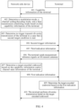
- FIG. 4 is a first schematic diagram of signaling interaction of a diversity transmission method according to an embodiment of this application. As shown in FIG. 4 , the method is implemented by a terminal and a network-side device in cooperation, and the method includes steps 401 to 410.
- Step 401 The terminal reports capability information of the terminal to the network-side device.
- the terminal includes BSC UE; and the capability information of the terminal includes at least one of the following: a modulation mode supported by the BSC UE and an antenna capability of the BSC UE.
- Step 402 The network-side device determines a modulation mode, a channel coding/decoding mode, and a data transmission scheduling mode based on the capability information of the terminal.
- Step 403 In a case that a second target condition is met, the network-side device determines to trigger transmit diversity transmission of the terminal.
- the second target condition includes at least one of the following: energy of a back-transmitted signal of the terminal is lower than a first threshold; the terminal is located at an edge of a cell; and the number of negative acknowledgements NACKs sent by the terminal exceeds a second threshold.
- Step 405 The network-side device sends third indication information to the terminal, where the third indication information is used to instruct the terminal to send measurement reference signals on M transmit antennas.
- the third indication information includes at least one of the following: information used to indicate a time or cycle of a measurement reference signal sent by the terminal on each of the M transmit antennas; information used to indicate a sequence of the measurement reference signal sent by the terminal on each of the M transmit antennas; and information used to indicate a frequency, a bandwidth, or a frequency shift of the measurement reference signal sent by the terminal on each of the M transmit antennas.
- Step 406 After the terminal receives the third indication information sent by the network-side device, the terminal sends the measurement reference signals on the M transmit antennas based on the third indication information.
- an implementation of sending the measurement reference signals on the M transmit antennas by the terminal based on the third indication information may include: the terminal separately sends the measurement reference signals on the M transmit antennas at different times based on the third indication information; or the terminal separately sends the measurement reference signals on the M transmit antennas at a same time based on the third indication information, where measurement reference signals sent on different transmit antennas have been scrambled by random numbers related to index information of the corresponding antennas.
- Step 408 The network-side device sends first indication information to the terminal, where the first indication information is used to indicate the target encoded codeword.
- the second trigger information and the first indication information may be carried together, that is, carried together in one piece of signaling, or may be carried separately, that is, carried by different signaling.
- the second trigger information and the third indication information may be carried together, that is, carried together in one piece of signaling, or may be carried separately, that is, carried by different signaling.
- Step 409 The terminal determines the target encoded codeword based on the first indication information.
- Step 410 The terminal performs diversity transmission based on the target encoded codeword.
- a manner of carrying the first indication information includes one of the following: the first indication message is carried by DCI; the first indication information is carried by a preamble sequence; the first indication information is carried by a signal sequence, where the signal sequence includes a signal sequence scrambled by a BSC UE ID or a random number related to BSC UE, or a signal sequence carrying a BSC UE ID; and the first indication information is carried by a MAC CE.
- the DCI may be a newly designed DCI format or existing DCI.
- the network-side device determines the target encoded codeword meeting the target encoding structure and sends the target encoded codeword to the terminal, to instruct the terminal to perform multi-antenna transmit diversity transmission by using the target encoded codeword, where the target encoded codeword is the encoding matrix with N ⁇ N dimensions;
- the target encoding structure includes the first basic element, the second basic element, the first generation element, and the second generation element; the first generation element is the opposite number of the conjugate operation result of the first basic element, and the second generation element is the conjugate operation result of the second basic element; and the first basic element, the second basic element, the first generation element, and the second generation element are complex numbers or block matrices.
- the target encoded codeword designed based on the target encoding structure in this embodiment of this application can not only ensure a diversity gain, but also reduce types of reflection coefficients required on each antenna, that is, reduce types of load impedances required on each antenna, thereby reducing system implementation complexity and effectively reducing a probability of error detection.
- Scenario 2 The terminal triggers diversity transmission of the terminal, and the network-side device determines and indicates a codebook.
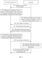
- FIG. 5 is a second schematic diagram of signaling interaction of a diversity transmission method according to an embodiment of this application. As shown in FIG. 5 , the method is implemented by a terminal and a network-side device in cooperation, and the method includes steps 501 to 510.
- Step 501 The terminal reports capability information of the terminal to the network-side device.
- the terminal includes BSC UE; and the capability information of the terminal includes at least one of the following: a modulation mode supported by the BSC UE and an antenna capability of the BSC UE.
- Step 502 The network-side device determines a modulation mode, a channel coding/decoding mode, and a data transmission scheduling mode based on the capability information of the terminal.
- Step 504 The terminal sends first trigger information to the network-side device, where the first trigger information is used to indicate to the network-side device that the terminal triggers diversity transmission.
- Step 505 The network-side device sends third indication information to the terminal, where the third indication information is used to instruct the terminal to send measurement reference signals on M transmit antennas.
- Step 508 The network-side device sends first indication information to the terminal, where the first indication information is used to indicate the target encoded codeword.
- step 505 and step 508 are not limited in this embodiment of this application. Either of step 505 and step 508 may be performed first, or the steps may be performed simultaneously.
- Step 509 The terminal determines the target encoded codeword based on the first indication information.
- Step 510 The terminal performs diversity transmission based on the target encoded codeword.
- a manner of carrying the first indication information includes one of the following: the first indication message is carried by DCI; the first indication information is carried by a preamble sequence; the first indication information is carried by a signal sequence, where the signal sequence includes a signal sequence scrambled by a BSC UE ID or a random number related to BSC UE, or a signal sequence carrying a BSC UE ID; and the first indication information is carried by a MAC CE.
- the DCI may be a newly designed DCI format or existing DCI.
- the network-side device determines the target encoded codeword meeting the target encoding structure and sends the target encoded codeword to the terminal, to instruct the terminal to perform multi-antenna transmit diversity transmission by using the target encoded codeword, where the target encoded codeword is the encoding matrix with N ⁇ N dimensions;
- the target encoding structure includes the first basic element, the second basic element, the first generation element, and the second generation element; the first generation element is the opposite number of the conjugate operation result of the first basic element, and the second generation element is the conjugate operation result of the second basic element; and the first basic element, the second basic element, the first generation element, and the second generation element are complex numbers or block matrices.
- the target encoded codeword designed based on the target encoding structure in this embodiment of this application can not only ensure a diversity gain, but also reduce types of reflection coefficients required on each antenna, that is, reduce types of load impedances required on each antenna, thereby reducing system implementation complexity and effectively reducing a probability of error detection.
- Scenario 3 The network-side device triggers diversity transmission of the terminal, and the terminal determines and indicates a codebook.
- the terminal includes BSC UE; and the capability information of the terminal includes at least one of the following: a modulation mode supported by the BSC UE and an antenna capability of the BSC UE.
- Step 602 The network-side device determines a modulation mode, a channel coding/decoding mode, and a data transmission scheduling mode based on the capability information of the terminal.
- Step 603 In a case that a second target condition is met, the network-side device determines to trigger transmit diversity transmission of the terminal.
- the second target condition includes at least one of the following: energy of a back-transmitted signal of the terminal is lower than a first threshold; the terminal is located at an edge of a cell; and the number of negative acknowledgements NACKs sent by the terminal exceeds a second threshold.
- Step 604 The network-side device sends second trigger information to the terminal, where the second trigger information is used to trigger diversity transmission of the terminal.
- Step 605 The network-side device sends third indication information to the terminal, where the third indication information is used to instruct the terminal to send measurement reference signals on M transmit antennas.
- the second trigger information and the third indication information may be carried together, that is, carried together in one piece of signaling, or may be carried separately.
- the third indication information includes at least one of the following: information used to indicate a time or cycle of a measurement reference signal sent by the terminal on each of the M transmit antennas; information used to indicate a sequence of the measurement reference signal sent by the terminal on each of the M transmit antennas; and information used to indicate a frequency, a bandwidth, or a frequency shift of the measurement reference signal sent by the terminal on each of the M transmit antennas.
- Step 608 The terminal sends second indication information to the network-side device, where the second indication information is used to indicate the target encoded codeword.
- the second indication information includes at least one of the following: a transmit diversity order and a codeword matrix indicator; and codebook dimension indication information and a codeword matrix indicator.
- a manner of carrying the second indication information includes one of the following: the second indication information is carried by a MAC CE; the second indication information is carried by a preamble; and the second indication information is carried by a sequence.
- step 604 and step 605 are not limited in this embodiment of this application. Either of step 604 and step 605 may be performed first, or the steps may be performed simultaneously.
- Step 609 The terminal performs diversity transmission based on the target encoded codeword.
- the target encoded codeword designed based on the target encoding structure in this embodiment of this application can not only ensure a diversity gain, but also reduce types of reflection coefficients required on each antenna, that is, reduce types of load impedances required on each antenna, thereby reducing system implementation complexity and effectively reducing a probability of error detection.
- Scenario 4 The terminal triggers diversity transmission of the terminal, and the terminal determines and indicates the codebook.
- FIG. 7 is a fourth schematic diagram of signaling interaction of a diversity transmission method according to an embodiment of this application. As shown in FIG. 7 , the method includes steps 701 to 709.
- Step 701 The terminal reports capability information of the terminal to the network-side device.
- the terminal includes BSC UE; and the capability information of the terminal includes at least one of the following: a modulation mode supported by the BSC UE and an antenna capability of the BSC UE.
- Step 702 The network-side device determines a modulation mode, a channel coding/decoding mode, and a data transmission scheduling mode based on the capability information of the terminal.
- Step 703 In a case that a first target condition is met, the terminal determines to trigger transmit diversity transmission.
- Step 704 The terminal sends first trigger information to the network-side device, where the first trigger information is used to indicate to the network-side device that the terminal triggers diversity transmission.
- Step 705 The network-side device sends third indication information to the terminal, where the third indication information is used to instruct the terminal to send measurement reference signals on M transmit antennas.
- the third indication information includes at least one of the following: information used to indicate a time or cycle of a measurement reference signal sent by the terminal on each of the M transmit antennas; information used to indicate a sequence of the measurement reference signal sent by the terminal on each of the M transmit antennas; and information used to indicate a frequency, a bandwidth, or a frequency shift of the measurement reference signal sent by the terminal on each of the M transmit antennas.
- a manner of carrying the third indication information includes one of the following: the third indication information is carried by DCI; the third indication information is carried by a preamble sequence; the third indication information is carried by a signal sequence, where the signal sequence includes a signal sequence scrambled by a B SC UE ID or scrambled by a random number related to B SC UE, or a signal sequence carrying a BSC UE ID; and the third indication information is carried by a MAC CE.
- Step 706 After the terminal receives the third indication information sent by the network-side device, the terminal sends the measurement reference signals on the M transmit antennas based on the third indication information.
- Step 707 The terminal determines a target encoded codeword based on the capability information and/or channel state information of the terminal, where
- the target encoded codeword meets a target encoding structure;
- the target encoding structure includes a first basic element, a second basic element, a first generation element, and a second generation element;
- the first generation element is an opposite number of a conjugate operation result of the first basic element, and the second generation element is a conjugate operation result of the second basic element;
- the first basic element, the second basic element, the first generation element, and the second generation element are complex numbers or block matrices.
- the second indication information includes at least one of the following: a transmit diversity order and a codeword matrix indicator; and codebook dimension indication information and a codeword matrix indicator.
- step 704 and step 708 are not limited in this embodiment of this application. Either of step 704 and step 708 may be performed first, or the steps may be performed simultaneously.
- Step 709 The terminal performs diversity transmission based on the target encoded codeword.
- the terminal autonomously determines the target encoded codeword meeting the target encoding structure and sends the target encoded codeword to the network-side device, where the target encoded codeword is the encoding matrix with N ⁇ N dimensions;
- the target encoding structure includes the first basic element, the second basic element, the first generation element, and the second generation element;
- the first generation element is the opposite number of the conjugate operation result of the first basic element, and the second generation element is the conjugate operation result of the second basic element;
- the first basic element, the second basic element, the first generation element, and the second generation element are complex numbers or block matrices.
- the target encoded codeword designed based on the target encoding structure in this embodiment of this application can not only ensure a diversity gain, but also reduce types of reflection coefficients required on each antenna, that is, reduce types of load impedances required on each antenna, thereby reducing system implementation complexity and effectively reducing a probability of error detection.
- the diversity transmission method provided in the embodiments of this application may be performed by a diversity transmission apparatus.
- a diversity transmission apparatus provided in the embodiments of this application is described by assuming that the diversity transmission method in the embodiments of this application is performed by the diversity transmission apparatus.
- FIG. 8 is a first schematic structural diagram of a diversity transmission apparatus according to an embodiment of this application. As shown in FIG. 8 , the diversity transmission apparatus 800 is applied to a terminal and includes a first determining module 801 and a transmission module 802.
- the first determining module 801 is configured to determine a target encoded codeword
- the diversity transmission apparatus determines the target encoded codeword meeting the target encoding structure and performs multi-antenna transmit diversity transmission by using the target encoded codeword, where the target encoded codeword is the encoding matrix with N ⁇ N dimensions; the target encoding structure includes the first basic element, the second basic element, the first generation element, and the second generation element; the first generation element is the opposite number of the conjugate operation result of the first basic element, and the second generation element is the conjugate operation result of the second basic element; and the first basic element, the second basic element, the first generation element, and the second generation element are complex numbers or block matrices.
- the target encoded codeword designed based on the target encoding structure in the embodiments of this application can not only ensure a diversity gain, but also reduce types of reflection coefficients required on each antenna, that is, reduce types of load impedances required on each antenna, thereby reducing system implementation complexity and effectively reducing a probability of error detection.
- the first determining module 801 is specifically configured to:
- the first indication information includes at least one of the following:
- a manner of carrying the first indication information includes one of the following:
- the first determining module 801 is specifically configured to determine the target encoded codeword based on capability information and/or channel state information of the terminal.
- the diversity transmission apparatus 800 further includes: a second sending module, configured to send second indication information to a network-side device, where the second indication information is used to indicate the target encoded codeword.
- a second sending module configured to send second indication information to a network-side device, where the second indication information is used to indicate the target encoded codeword.
- the second indication information includes at least one of the following:
- a manner of carrying the second indication information includes one of the following:
- the first determining module 801 is specifically configured to determine the target encoded codeword in a case that a first target condition is met.
- the diversity transmission apparatus 800 further includes: a third sending module, configured to send first trigger information to a network-side device in a case that a first target condition is met, where the first trigger information is used to indicate to the network-side device that the terminal triggers diversity transmission.
- a third sending module configured to send first trigger information to a network-side device in a case that a first target condition is met, where the first trigger information is used to indicate to the network-side device that the terminal triggers diversity transmission.
- the first target condition includes at least one of the following:
- the diversity transmission apparatus 800 further includes: a first receiving module, configured to receive second trigger information sent by a network-side device, where the second trigger information is used to trigger diversity transmission of the terminal.
- a manner of carrying the second trigger information includes one of the following:
- the diversity transmission apparatus 800 further includes:
- the fourth sending module is specifically configured to:
- the third indication information includes at least one of the following:
- a manner of carrying the third indication information includes one of the following:
- the diversity transmission apparatus in this embodiment of this application may be an electronic device, for example, an electronic device with an operating system, or may be a component in an electronic device, for example, an integrated circuit or a chip.
- the electronic device may be a terminal, or may be other devices than a terminal.
- the terminal may include but is not limited to the foregoing illustrated type of the terminal 11.
- the other devices may be a server, a network attached storage (Network Attached Storage, NAS), and the like. This is not specifically limited in this embodiment of this application.
- the diversity transmission apparatus provided in this embodiment of this application can implement each process implemented by the method embodiment in FIG. 2 , with the same technical effect achieved. To avoid repetition, details are not described herein again.
- FIG. 9 is a second schematic structural diagram of a diversity transmission apparatus according to an embodiment of this application. As shown in FIG. 9 , the diversity transmission apparatus 900 is applied to a network-side device and includes a second determining module 901 and a first sending module 902.
- the second determining module 901 is configured to determine a target encoded codeword
- the diversity transmission apparatus determines the target encoded codeword meeting the target encoding structure and sends the target encoded codeword to the terminal, to instruct the terminal to perform multi-antenna transmit diversity transmission by using the target encoded codeword, where the target encoded codeword is the encoding matrix with N ⁇ N dimensions; the target encoding structure includes the first basic element, the second basic element, the first generation element, and the second generation element; the first generation element is the opposite number of the conjugate operation result of the first basic element, and the second generation element is the conjugate operation result of the second basic element; and the first basic element, the second basic element, the first generation element, and the second generation element are complex numbers or block matrices.
- the target encoded codeword designed based on the target encoding structure in this embodiment of this application can not only ensure a diversity gain, but also reduce types of reflection coefficients required on each antenna, that is, reduce types of load impedances required on each antenna, thereby reducing system implementation complexity and effectively reducing a probability of error detection.
- the first indication information includes at least one of the following:
- a manner of carrying the first indication information includes one of the following:
- the second determining module 901 is specifically configured to determine the target encoded codeword based on capability information and/or channel state information of the terminal in a case that a second target condition is met.
- the second target condition includes at least one of the following:
- a manner of carrying the first trigger information includes one of the following:
- the diversity transmission apparatus 900 further includes: a fifth sending module, configured to send second trigger information to the terminal in a case that a second target condition is met, where the second trigger information is used to trigger diversity transmission of the terminal.
- a fifth sending module configured to send second trigger information to the terminal in a case that a second target condition is met, where the second trigger information is used to trigger diversity transmission of the terminal.
- a manner of carrying the second trigger information includes one of the following:
- the diversity transmission apparatus 900 further includes: a sixth sending module, configured to send third indication information to the terminal in a case that a second target condition is met, where the third indication information is used to instruct the terminal to send measurement reference signals on M transmit antennas.
- a sixth sending module configured to send third indication information to the terminal in a case that a second target condition is met, where the third indication information is used to instruct the terminal to send measurement reference signals on M transmit antennas.
- the third indication information includes at least one of the following:
- the diversity transmission apparatus provided in this embodiment of this application can implement each process implemented by the method embodiment in FIG. 3 , with the same technical effect achieved. To avoid repetition, details are not described herein again.
- the diversity transmission apparatus in this embodiment of this application may be an electronic device, or may be a component such as an integrated circuit or a chip in an electronic device.
- the electronic device may be a terminal, or may be other devices than a terminal.
- the electronic device may be a mobile phone, a tablet personal computer, a notebook computer, a palmtop computer, an in-vehicle electronic device, a mobile Internet device (Mobile Internet Device, MID), an augmented reality (augmented reality, AR) or virtual reality (virtual reality, VR) device, a robot, a wearable device, an ultra-mobile personal computer (ultra-mobile personal computer, UMPC), a netbook, a personal digital assistant (personal digital assistant, PDA), or the like; or the electronic device may be a server, a network attached storage (Network Attached Storage, NAS), a personal computer (personal computer, PC), a television (television, TV), a teller machine, a self-service machine, or the like. This is not specifically limited in this embodiment of this
- the diversity transmission apparatus in this embodiment of this application may be an apparatus with an operating system.
- the operating system may be an Android (Android) operating system, an iOS operating system, or other possible operating systems, and is not specifically limited in this embodiment of this application.
- FIG. 10 is a schematic structural diagram of a communication device according to an embodiment of this application.
- the communication device 1000 includes a processor 1001 and a memory 1002.
- the memory 1002 stores a program or instructions executable on the processor 1001.
- the communication device 1000 is a terminal, and the program or instructions are executed by the processor 1001, each step of the foregoing embodiment of the diversity transmission method is implemented, with the same technical effect achieved.
- the communication device 1000 is a network-side device, and the program or instructions are executed by the processor 1001, each step of the foregoing embodiment of the diversity transmission method is implemented, with the same technical effect achieved. To avoid repetition, details are not described herein again.
- An embodiment of this application further provides a terminal, including a processor and a communication interface.
- the processor is configured to determine a target encoded codeword; and the communication interface is configured to perform diversity transmission based on the target encoded codeword, where the target encoded codeword meets a target encoding structure;
- the target encoding structure includes a first basic element, a second basic element, a first generation element, and a second generation element;
- the first generation element is an opposite number of a conjugate operation result of the first basic element, and the second generation element is a conjugate operation result of the second basic element; and the first basic element, the second basic element, the first generation element, and the second generation element are complex numbers or block matrices.
- the terminal embodiment corresponds to the foregoing terminal-side method embodiment, and each implementation process and implementation of the foregoing method embodiment can be applied to the terminal embodiment, with the same technical effect achieved.
- FIG. 11 is a schematic structural diagram of a terminal according to an embodiment of this application.
- the terminal 1100 includes but is not limited to at least some components such as a radio frequency unit 1101, a network module 1102, an audio output unit 1103, an input unit 1104, a sensor 1105, a display unit 1106, a user input unit 1107, an interface unit 1108, a memory 1109, and a processor 1110.
- the terminal 1100 may further include a power supply (for example, a battery) supplying power to all components.
- the power supply may be logically connected to the processor 1110 through a power management system. In this way, functions such as charge management, discharge management, and power consumption management are implemented by using the power management system.
- the terminal structure shown in FIG. 11 does not constitute a limitation on the terminal.
- the terminal may include more or fewer components than those shown in the figure, or some components are combined, or component arrangements are different. Details are not described herein again.
- the input unit 1104 may include a graphics processing unit (Graphics Processing Unit, GPU) 11041 and a microphone 11042.
- the graphics processing unit 11041 processes image data of a still picture or video obtained by an image capture apparatus (such as a camera) in a video capture mode or an image capture mode.
- the display unit 1106 may include a display panel 11061, and the display panel 11061 may be configured in a form of a liquid crystal display, an organic light-emitting diode, or the like.
- the user input unit 1107 includes at least one of a touch panel 11071 and other input devices 11072.
- the touch panel 11071 is also referred to as a touchscreen.
- the touch panel 11071 may include two parts: a touch detection apparatus and a touch controller.
- the other input devices 11072 may include but are not limited to a physical keyboard, a function button (such as a volume control button or a power button), a trackball, a mouse, and a joystick. Details are not described herein again.
- the radio frequency unit 1101 may transmit the downlink data to the processor 1110 for processing.
- the radio frequency unit 1101 may send uplink data to the network-side device.
- the radio frequency unit 1101 includes but is not limited to an antenna, an amplifier, a transceiver, a coupler, a low noise amplifier, a duplexer, and the like.
- the memory 1109 may be configured to store software programs or instructions and various data.
- the memory 1109 may primarily include a first storage area for storing programs or instructions and a second storage area for storing data.
- the first storage area may store an operating system, an application program or instructions required by at least one function (such as an audio play function and an image play function), and the like.
- the memory 1109 may include a volatile memory or a non-volatile memory, or the memory 1109 may include both a volatile memory and a non-volatile memory.
- the non-volatile memory may be a read-only memory (Read-Only Memory, ROM), a programmable read-only memory (Programmable ROM, PROM), an erasable programmable read-only memory (Erasable PROM, EPROM), an electrically erasable programmable read-only memory (Electrically EPROM, EEPROM), or a flash memory.
- ROM Read-Only Memory
- PROM programmable read-only memory
- Erasable PROM Erasable PROM
- EPROM electrically erasable programmable read-only memory
- EEPROM electrically erasable programmable read-only memory
- the volatile memory may be a random access memory (Random Access Memory, RAM), a static random access memory (Static RAM, SRAM), a dynamic random access memory (Dynamic RAM, DRAM), a synchronous dynamic random access memory (Synchronous DRAM, SDRAM), a double data rate synchronous dynamic random access memory (Double Data rate SDRAM, DDR SDRAM), an enhanced synchronous dynamic random access memory (Enhanced SDRAM, ESDRAM), a synchlink dynamic random access memory (Synch Link DRAM, SLDRAM), and a direct rambus random access memory (Direct Rambus RAM, DRRAM).
- RAM Random Access Memory
- SRAM static random access memory
- DRAM dynamic random access memory
- DRAM synchronous dynamic random access memory
- SDRAM double data rate synchronous dynamic random access memory
- Enhanced SDRAM, ESDRAM enhanced synchronous dynamic random access memory
- Synch Link DRAM Synchlink dynamic random access memory
- SLDRAM direct rambus random access memory
- Direct Rambus RAM Direct Rambus RAM,
- the processor 1110 may include one or more processing units.
- the processor 1110 integrates an application processor and a modem processor.
- the application processor mainly processes operations related to the operating system, a user interface, an application program, and the like.
- the modem processor mainly processes a wireless communication signal.
- the modem processor is a baseband processor. It may be understood that the modem processor may alternatively be not integrated in the processor 1110.
- the processor 1110 is configured to determine a target encoded codeword
- the terminal provided in this embodiment of this application determines the target encoded codeword meeting the target encoding structure and performs multi-antenna transmit diversity transmission by using the target encoded codeword, where the target encoded codeword is the encoding matrix with N ⁇ N dimensions; the target encoding structure includes the first basic element, the second basic element, the first generation element, and the second generation element; the first generation element is the opposite number of the conjugate operation result of the first basic element, and the second generation element is the conjugate operation result of the second basic element; and the first basic element, the second basic element, the first generation element, and the second generation element are complex numbers or block matrices.
- the target encoded codeword designed based on the target encoding structure in the embodiments of this application can not only ensure a diversity gain, but also reduce types of reflection coefficients required on each antenna, that is, reduce types of load impedances required on each antenna, thereby reducing system implementation complexity and effectively reducing a probability of error detection.
- An embodiment of this application further provides a network-side device, including a processor and a communication interface.
- the processor is configured to determine a target encoded codeword in a case that a second target condition is met; and the communication interface is configured to send first indication information to a terminal, where the first indication information is used to indicate the target encoded codeword, where
- the network-side device embodiment corresponds to the foregoing method embodiment of the network-side device, and each implementation process and implementation of the foregoing method embodiment can be applied to the network-side device embodiment, with the same technical effect achieved.
- FIG. 12 is a schematic structural diagram of a network-side device according to an embodiment of this application.
- the network-side device 1200 includes an antenna 1201, a radio frequency apparatus 1202, a baseband apparatus 1203, a processor 1204, and a memory 1205.
- the antenna 1201 is connected to the radio frequency apparatus 1202.
- the radio frequency apparatus 1202 receives information by using the antenna 1201, and sends the received information to the baseband apparatus 1203 for processing.
- the baseband apparatus 1203 processes to-be-sent information, and sends the information to the radio frequency apparatus 1202; and the radio frequency apparatus 1202 processes the received information and then sends the information out by using the antenna 1201.
- the method performed by the network-side device in the foregoing embodiment may be implemented in the baseband apparatus 1203.
- the baseband apparatus 1203 includes a baseband processor.
- the baseband apparatus 1203 may include, for example, at least one baseband unit, where a plurality of chips are disposed on the baseband unit. As shown in FIG. 12 , one of the chips is, for example, the baseband processor, connected to the memory 1205 by using a bus interface, to invoke a program in the memory 1205 to perform the operation of the network-side device shown in the foregoing method embodiment.
- the network-side device may further include a network interface 1206, where the interface is, for example, a common public radio interface (common public radio interface, CPRI).
- a common public radio interface common public radio interface, CPRI
- the network-side device 1200 in this embodiment of the present invention further includes a program or instructions stored in the memory 1205 and executable on the processor 1204.
- the processor 1204 invokes the program or instructions in the memory 1205, the method performed by each module shown in FIG. 7 is performed, with the same technical effect achieved. To avoid repetition, details are not described herein again.
- An embodiment of this application further provides a diversity transmission system, including a terminal and a network-side device.
- the terminal may be configured to perform the steps of the foregoing diversity transmission method.
- the network-side device may be configured to perform the steps of the foregoing diversity transmission method.
- An embodiment of this application further provides a readable storage medium.
- the readable storage medium may be volatile or non-volatile.
- the readable storage medium stores a program or instructions. When the program or instructions are executed by a processor, each process of the foregoing embodiment of the diversity transmission method is implemented, with the same technical effect achieved. To avoid repetition, details are not described herein again.
- the processor is a processor in the terminal in the foregoing embodiment.
- the readable storage medium includes a computer-readable storage medium, such as a computer read-only memory ROM, a random access memory RAM, a magnetic disk, or an optical disc.
- an embodiment of this application provides a chip.
- the chip includes a processor and a communication interface.
- the communication interface is coupled to the processor.
- the processor is configured to run a program or instructions to implement each process of the embodiment of the diversity transmission method, with the same technical effect achieved. To avoid repetition, details are not described herein again.
- the chip provided in this embodiment of this application may also be referred to as a system-level chip, a system chip, a chip system, a system-on-chip, or the like.
- an embodiment of this application provides a computer program or program product.
- the computer program or program product is stored in a storage medium.
- the computer program or program product is executed by at least one processor to implement each process of the foregoing embodiment of the diversity transmission method, with the same technical effect achieved. To avoid repetition, details are not described herein again.
- the computer software product is stored in a storage medium (such as a ROM/RAM, a magnetic disk, or an optical disc), and includes several instructions for instructing a terminal (which may be a mobile phone, a computer, a server, an air conditioner, a network device, or the like) to perform the methods described in the embodiments of this application.
- a storage medium such as a ROM/RAM, a magnetic disk, or an optical disc
- a terminal which may be a mobile phone, a computer, a server, an air conditioner, a network device, or the like
Landscapes
- Engineering & Computer Science (AREA)
- Computer Networks & Wireless Communication (AREA)
- Signal Processing (AREA)
- Quality & Reliability (AREA)
- Physics & Mathematics (AREA)
- Mathematical Physics (AREA)
- Radio Transmission System (AREA)
- Mobile Radio Communication Systems (AREA)
Abstract
Description
- This application claims priority to
Chinese Patent Application No. 202111484934.3, filed on December 7, 2021 - This application pertains to the field of communications technologies, and specifically relates to a diversity transmission method, a terminal, and a network-side device.
- With development of mobile communications technologies, a communications network needs to support the massive Internet of everything. Massive Internet of Things (Internet of Things, loT) devices pose new challenges in terms of costs and power consumption. Therefore, a main trend in development of Internet of Things devices includes cellular networking, low costs, low power consumption, and even passive zero power consumption. However, conventional passive terminals are limited by their power consumption and hardware capabilities, and communication transmission distances of most of the terminals are less than 10 meters, far from a goal of cellular coverage of 100 meters. In consideration of this, a backscatter communications technology may be used to effectively increase communication distances of the Internet of Things devices. Backscatter communication means that backscatter communication user equipment uses a radio frequency signal from another device or in an environment to perform signal modulation to transmit information of the backscatter communication user equipment.
- In the related art, signal redundancy is introduced in space domain and time domain by using a space time block code (Space Time Block Code, STBC), and a diversity gain and an antenna gain are achieved by properly constructing a block code transmission matrix without increasing a bandwidth. Although an orthogonal space time block code (Orthogonal Space Time Block Code, OSTBC) codebook can achieve a full rate while achieving a full diversity gain, this type of codebook is applicable only to a two-antenna transmit diversity scenario. A quasi-orthogonal space time block code (Quasi-Orthogonal Space Time Block Code, QSTBC) codebook may be extended to a transmit diversity scenario with more than two antennas, and achieve a full rate while achieving a diversity gain slightly worse than a full diversity gain.
- Actually, because backscatter communication controls an amplitude or a phase of a signal by changing a load impedance, considering other non-ideal factors in a modulation circuit for backscatter communication, there are more or less errors in an amplitude or a phase of an output signal. However, OSTBC and QSTBC diversity schemes are both designed for conventional active radio frequency communication and do not consider modulation characteristics of passive terminals such as backscatter communication. When the OSTBC and QSTBC diversity schemes are applied in backscatter communications, there are problems of high system implementation complexity and a high probability of error detection.
- Embodiments of this application provide a diversity transmission method, a terminal, and a network-side device to resolve problems of high system implementation complexity and a high probability of error detection.
- According to a first aspect, a diversity transmission method is provided. The method is applied to a terminal and includes:
- determining, by the terminal, a target encoded codeword; and
- performing, by the terminal, diversity transmission based on the target encoded codeword, where
- the target encoded codeword meets a target encoding structure; the target encoded codeword is an encoding matrix with N×N dimensions; N= 2 k , and k is a positive integer;
- the target encoding structure includes a first basic element, a second basic element, a first generation element, and a second generation element; the first generation element is an opposite number of a conjugate operation result of the first basic element, and the second generation element is a conjugate operation result of the second basic element; and the first basic element, the second basic element, the first generation element, and the second generation element are complex numbers or block matrices.
- According to a second aspect, a diversity transmission method is provided. The method is applied to a network-side device and includes:
- determining, by the network-side device, a target encoded codeword; and
- sending, by the network-side device, first indication information to a terminal, where the first indication information is used to indicate the target encoded codeword, where
- the target encoded codeword meets a target encoding structure; the target encoded codeword is an encoding matrix with N×N dimensions; N= 2 k , and k is a positive integer; the target encoding structure includes a first basic element, a second basic element, a first generation element, and a second generation element; the first generation element is an opposite number of a conjugate operation result of the first basic element, and the second generation element is a conjugate operation result of the second basic element; and the first basic element, the second basic element, the first generation element, and the second generation element are complex numbers or block matrices.
- According to a third aspect, a diversity transmission apparatus is provided. The apparatus is applied to a terminal and includes:
- a first determining module, configured to determine a target encoded codeword; and
- a transmission module, configured to perform diversity transmission based on the target encoded codeword, where
- the target encoded codeword meets a target encoding structure; the target encoded codeword is an encoding matrix with N×N dimensions; N= 2 k , and k is a positive integer; the target encoding structure includes a first basic element, a second basic element, a first generation element, and a second generation element; the first generation element is an opposite number of a conjugate operation result of the first basic element, and the second generation element is a conjugate operation result of the second basic element; and the first basic element, the second basic element, the first generation element, and the second generation element are complex numbers or block matrices.
- According to a fourth aspect, a diversity transmission apparatus is provided. The apparatus is applied to a network-side device and includes:
- a second determining module, configured to determine a target encoded codeword; and
- a first sending module, configured to send first indication information to a terminal, where the first indication information is used to indicate the target encoded codeword, where
- the target encoded codeword meets a target encoding structure; the target encoded codeword is an encoding matrix with N×N dimensions; N= 2 k , and k is a positive integer; the target encoding structure includes a first basic element, a second basic element, a first generation element, and a second generation element; the first generation element is an opposite number of a conjugate operation result of the first basic element, and the second generation element is a conjugate operation result of the second basic element; and the first basic element, the second basic element, the first generation element, and the second generation element are complex numbers or block matrices.
- According to a fifth aspect, a terminal is provided. The terminal includes a processor and a memory. The memory stores a program or instructions executable on the processor. When the program or instructions are executed by the processor, the steps of the method according to the first aspect are implemented.
- According to a sixth aspect, a terminal is provided and includes a processor and a communication interface. The processor is configured to determine a target encoded codeword; and the communication interface is configured to perform diversity transmission based on the target encoded codeword, where
the target encoded codeword meets a target encoding structure; the target encoded codeword is an encoding matrix with N×N dimensions; N= 2 k , and k is a positive integer; the target encoding structure includes a first basic element, a second basic element, a first generation element, and a second generation element; the first generation element is an opposite number of a conjugate operation result of the first basic element, and the second generation element is a conjugate operation result of the second basic element; and the first basic element, the second basic element, the first generation element, and the second generation element are complex numbers or block matrices. - According to a seventh aspect, a network-side device is provided. The network-side device includes a processor and a memory. The memory stores a program or instructions executable on the processor. When the program or instructions are executed by the processor, the steps of the method according to the second aspect are implemented.
- According to an eighth aspect, a network-side device is provided and includes a processor and a communication interface. The processor is configured to determine a target encoded codeword; and the communication interface is configured to send first indication information to a terminal, where the first indication information is used to indicate the target encoded codeword, where
- the target encoded codeword meets a target encoding structure; the target encoded codeword is an encoding matrix with N×N dimensions; N= 2 k , and k is a positive integer;
- the target encoding structure includes a first basic element, a second basic element, a first generation element, and a second generation element; the first generation element is an opposite number of a conjugate operation result of the first basic element, and the second generation element is a conjugate operation result of the second basic element; and the first basic element, the second basic element, the first generation element, and the second generation element are complex numbers or block matrices.
- According to a ninth aspect, a diversity transmission system is provided and includes a terminal and a network-side device. The terminal may be configured to perform the steps of the diversity transmission method according to the first aspect. The network-side device may be configured to perform the steps of the diversity transmission method according to the second aspect.
- According to a tenth aspect, a readable storage medium is provided. The readable storage medium stores a program or instructions. When the program or instructions are executed by a processor, the steps of the method according to the first aspect are implemented, or the steps of the method according to the second aspect are implemented.
- According to an eleventh aspect, a chip is provided. The chip includes a processor and a communication interface. The communication interface is coupled to the processor. The processor is configured to run a program or instructions to implement the method according to the first aspect or implement the method according to the second aspect.
- According to a twelfth aspect, a computer program or program product is provided. The computer program or program product is stored in a storage medium. The computer program or program product is executed by at least one processor to implement the steps of the method according to the first aspect or implement the steps of the method according to the second aspect.
- In the embodiments of this application, the terminal determines the target encoded codeword meeting the target encoding structure and performs multi-antenna transmit diversity transmission by using the target encoded codeword, where the target encoded codeword is the encoding matrix with N×N dimensions; the target encoding structure includes the first basic element, the second basic element, the first generation element, and the second generation element; the first generation element is the opposite number of the conjugate operation result of the first basic element, and the second generation element is the conjugate operation result of the second basic element; and the first basic element, the second basic element, the first generation element, and the second generation element are complex numbers or block matrices. In comparison with the related art, the target encoded codeword designed based on the target encoding structure in the embodiments of this application can not only ensure a diversity gain, but also reduce types of reflection coefficients required on each antenna, that is, reduce types of load impedances required on each antenna, thereby reducing system implementation complexity and effectively reducing a probability of error detection.
-
-
FIG. 1 is a schematic diagram of a wireless communications system to which an embodiment of this application can be applied; -
FIG. 2 is a first schematic flowchart of a diversity transmission method according to an embodiment of this application; -
FIG. 3 is a second schematic flowchart of a diversity transmission method according to an embodiment of this application; -
FIG. 4 is a first schematic diagram of signaling interaction of a diversity transmission method according to an embodiment of this application; -
FIG. 5 is a second schematic diagram of signaling interaction of a diversity transmission method according to an embodiment of this application; -
FIG. 6 is a third schematic diagram of signaling interaction of a diversity transmission method according to an embodiment of this application; -
FIG. 7 is a fourth schematic diagram of signaling interaction of a diversity transmission method according to an embodiment of this application; -
FIG. 8 is a first schematic structural diagram of a diversity transmission apparatus according to an embodiment of this application; -
FIG. 9 is a second schematic structural diagram of a diversity transmission apparatus according to an embodiment of this application; -
FIG. 10 is a schematic structural diagram of a communication device according to an embodiment of this application; -
FIG. 11 is a schematic structural diagram of a terminal according to an embodiment of this application; and -
FIG. 12 is a schematic structural diagram of a network-side device according to an embodiment of this application. - The following clearly describes the technical solutions in the embodiments of this application with reference to the accompanying drawings in the embodiments of this application. Apparently, the described embodiments are only some rather than all of the embodiments of this application. All other embodiments obtained by a person of ordinary skill in the art based on the embodiments of this application shall fall within the protection scope of this application.
- The terms "first", "second", and the like in this specification and claims of this application are used to distinguish between similar objects instead of describing a specific order or sequence. It should be understood that the terms used in this way are interchangeable in appropriate circumstances, so that the embodiments of this application can be implemented in other orders than the order illustrated or described herein. In addition, objects distinguished by "first" and "second" usually fall within one class, and a quantity of objects is not limited. For example, there may be one or more first objects. In addition, the term "and/or" in the specification and claims indicates at least one of connected objects, and the character "/" generally represents an "or" relationship between associated objects.
- It should be noted that technologies described in the embodiments of this application are not limited to a long term evolution (Long Term Evolution, LTE)/LTE-Advanced (LTE-Advanced, LTE-A) system, and can also be used in other wireless communications systems, such as code division multiple access (Code Division Multiple Access, CDMA), time division multiple access (Time Division Multiple Access, TDMA), frequency division multiple access (Frequency Division Multiple Access, FDMA), orthogonal frequency division multiple access (Orthogonal Frequency Division Multiple Access, OFDMA), single-carrier frequency-division multiple access (Single-carrier Frequency-Division Multiple Access, SC-FDMA), and other systems. The terms "system" and "network" in the embodiments of this application are usually used interchangeably. The described technologies may be used for the foregoing systems and radio technologies, and may also be used for other systems and radio technologies. However, in the following descriptions, the new radio (New Radio, NR) system is described for an illustrative purpose, and NR terms are used in most of the following descriptions. These technologies may also be applied to other communications systems than the NR system, for example, a 6th Generation (6th Generation, 6G) communications system.
-
FIG. 1 is a schematic diagram of a wireless communications system to which an embodiment of this application can be applied. The wireless communications system shown inFIG. 1 includes a terminal 11 and a network-side device 12. The terminal 11 may be a terminal-side device such as backscatter communication user equipment (Backscatter Communication UE, BSC UE), a mobile phone, a tablet personal computer (Tablet Personal Computer), a laptop computer (Laptop Computer) or a notebook computer, a personal digital assistant (Personal Digital Assistant, PDA), a palmtop computer, a netbook, an ultra-mobile personal computer (ultra-mobile personal computer, UMPC), a mobile Internet device (Mobile Internet Device, MID), an augmented reality (augmented reality, AR) or virtual reality (virtual reality, VR) device, a robot, a wearable device (Wearable Device), vehicle user equipment (VUE), pedestrian user equipment (PUE), a smart home (a home device having a wireless communication function, such as a refrigerator, a television, a washing machine, or furniture), a game console, a personal computer (personal computer, PC), a teller machine, or a self-service machine. The BSC UE includes a tag (tag) in a radio frequency identification (Radio Frequency Identification, RFID) system, a passive (Passive) IoT device, a semi-passive (Semi-passive) IoT device, or the like. The wearable device includes a smartwatch, a smart band, a smart headphone, smart glasses, smart jewelry (a smart bracelet, a smart wrist chain, a smart ring, a smart necklace, a smart anklet, a smart ankle chain, or the like), a smart wristband, smart clothing, or the like. It should be noted that a specific type of the terminal 11 is not limited in the embodiments of this application. The network-side device 12 may include an access network device or a core network device. The access network device may also be referred to as a radio access network device, a radio access network (Radio Access Network, RAN), a radio access network function, or a radio access network element. Theaccess network device 12 may include a base station, a wireless local area network (Wireless Local Area Network, WLAN) access point, a Wireless Fidelity (Wireless Fidelity, Wi-Fi) node, or the like. The base station may be referred to as a NodeB, an evolved NodeB (eNB), an access point, a base transceiver station (Base Transceiver Station, BTS), a radio base station, a radio transceiver, a basic service set (Basic Service Set, BSS), an extended service set (Extended Service Set, ESS), a home NodeB, a home evolved NodeB, a transmission and reception point (Transmission and Reception Point, TRP), or another appropriate term in the art. As long as the same technical effect is achieved, the base station is not limited to specific technical terms. It should be noted that in the embodiments of this application, only a base station in an NR system is used as an example for description, but a specific type of the base station is not limited. The core network device may include but is not limited to at least one of the following: a core network node, a core network function, a mobility management entity (Mobility Management Entity, MME), an access and mobility management function (Access and Mobility Management Function, AMF), a session management function (Session Management Function, SMF), a user plane function (User Plane Function, UPF), a policy control function (Policy Control Function, PCF), a policy and charging rules function (Policy and Charging Rules Function, PCRF), an edge application server discovery function (Edge Application Server Discovery Function, EASDF), unified data management (Unified Data Management, UDM), a unified data repository (Unified Data Repository, UDR), a home subscriber server (Home Subscriber Server, HSS), a centralized network configuration (Centralized network configuration, CNC), a network repository function (Network Repository Function, NRF), a network exposure function (Network Exposure Function, NEF), a local NEF (Local NEF or L-NEF), a binding support function (Binding Support Function, BSF), an application function (Application Function, AF), or the like. It should be noted that in the embodiments of this application, only a core network device in the NR system is used as an example for description, but a specific type of the core network device is not limited. - A diversity transmission method provided in the embodiments of this application may be applied to a scenario of multi-antenna transmit diversity transmission to resolve problems of high system implementation complexity and a high probability of error detection in the related art. A target encoded codeword provided in the embodiments of this application meets a target encoding structure; the target encoded codeword is an encoding matrix with N×N dimensions; N= 2 k , and k is a positive integer; the target encoding structure includes a first basic element, a second basic element, a first generation element, and a second generation element; the first generation element is an opposite number of a conjugate operation result of the first basic element, and the second generation element is a conjugate operation result of the second basic element; and the first basic element, the second basic element, the first generation element, and the second generation element are complex numbers or block matrices.
- In the embodiments of this application, 2 k (k = 1, 2, 3, ...) antenna transmit diversity codewords may be obtained through construction based on the target encoding structure, and a transmit diversity order is 2 k . Apparently, more than one encoded codeword meets the target encoding structure. The target encoded codeword in the embodiments of this application is at least one of a plurality of encoded codewords that meet the target encoding structure.
- In comparison with the related art, in the embodiments of this application, in a case that a terminal obtains the target encoded codeword meeting the target encoding structure and performs multi-antenna transmit diversity transmission by using the target encoded codeword, the target encoded codeword designed based on the target encoding structure can not only ensure a diversity gain, but also reduce types of reflection coefficients required on each antenna, that is, reduce types of load impedances required on each antenna, thereby reducing system implementation complexity and effectively reducing a probability of error detection.
- The diversity transmission method provided in the embodiments of this application is hereinafter described in detail by using some embodiments and application scenarios thereof with reference to the accompanying drawings. It may be understood that different embodiments may be combined with each other, and that same or similar concepts or step processes are not repeated.
-
FIG. 2 is a first schematic flowchart of a diversity transmission method according to an embodiment of this application. As shown inFIG. 2 , the method includessteps - Step 201: A terminal determines a target encoded codeword.
- Step 202: The terminal performs diversity transmission based on the target encoded codeword, where
the target encoded codeword meets a target encoding structure; the target encoded codeword is an encoding matrix with N×N dimensions; N= 2 k , and k is a positive integer; the target encoding structure includes a first basic element, a second basic element, a first generation element, and a second generation element; the first generation element is an opposite number of a conjugate operation result of the first basic element, and the second generation element is a conjugate operation result of the second basic element; and the first basic element, the second basic element, the first generation element, and the second generation element are complex numbers or block matrices. - It should be noted that this embodiment of this application may be applied to a scenario of multi-antenna transmit diversity transmission of backscatter communication. The terminal includes backscatter communication user equipment (BSC UE). It may be understood that the BSC UE may include but is not limited to a tag in a radio frequency identification (RFID) system, a passive IoT device, a semi-passive IoT device, and the like.
- Optionally, the target encoded codeword may also be referred to as a codeword matrix, a block encoding matrix, a space time block encoding matrix, a block encoded codeword, or a space time block encoded codeword.
- In the diversity transmission method provided in this embodiment of this application, the terminal determines the target encoded codeword meeting the target encoding structure and performs multi-antenna transmit diversity transmission by using the target encoded codeword, where the target encoded codeword is the encoding matrix with N×N dimensions; the target encoding structure includes the first basic element, the second basic element, the first generation element, and the second generation element; the first generation element is the opposite number of the conjugate operation result of the first basic element, and the second generation element is the conjugate operation result of the second basic element; and the first basic element, the second basic element, the first generation element, and the second generation element are complex numbers or block matrices. In comparison with the related art, the target encoded codeword designed based on the target encoding structure in the embodiments of this application can not only ensure a diversity gain, but also reduce types of reflection coefficients required on each antenna, that is, reduce types of load impedances required on each antenna, thereby reducing system implementation complexity and effectively reducing a probability of error detection.
- Optionally, a characteristic of the target encoded codeword provided in this embodiment of this application is that the target encoded codeword with N×N dimensions meets the target encoding structure, and the target encoding structure may be represented by S ; and


- in a case that N is equal to 2, S 12, S 34,


- in a case that N is greater than 2, S 12, S 34,


- The target encoding structure determines that the target encoded codeword designed based on the target encoding structure can not only ensure the diversity gain, but also reduce the types of reflection coefficients required on each antenna, that is, reduce the types of load impedances required on each antenna, thereby reducing the system implementation complexity and effectively reducing the probability of error detection.
- In this embodiment of this application, the target encoded codeword (that is, a transmit diversity codebook) is designed based on the target encoding structure. Therefore, when the target encoded codeword meeting the target encoding structure is applied to a scenario of two-antenna transmit diversity transmission, the target encoded codeword can achieve a full diversity gain and a full rate. In this case, the target encoded codeword belongs to an OSTBC codebook. When the target encoded codeword meeting the target encoding structure is applied to a scenario of transmit diversity transmission with more than two transmit antennas, the target encoded codeword can achieve a diversity gain slightly worse than a full diversity gain and achieve full rate transmission. In this case, the target encoded codeword belongs to a QSTBC codebook.
- The following separately describes scenarios in which the target encoded codeword provided in this embodiment of this application is applied to two-antenna transmit diversity transmission, four-antenna transmit diversity transmission, and 2 k -antenna transmit diversity transmission.
- In the scenario of two-antenna transmit diversity transmission, the target encoded codeword has 2×2 dimensions, that is, N is equal to 2. In a case of S 12 = s 1, S 34 = s 2,


- Based on the target encoded codeword S 2, it is assumed that in a current symbol cycle, a symbol sent on antenna 1 is denoted as s 1, and a symbol sent on
antenna 2 is denoted as
antenna 2 is
- The following analyzes differences between the target encoded codeword S 2 provided in this embodiment of this application and a standard Alamouti code and an extended Alamouti codeword in the related art in backscatter communication.
- Assuming that the terminal performs transmission based on BPSK modulation symbols, according to a mapping principle of backscatter communication, a mapping rule between symbols 0 and 1 and reflection coefficients is

- Table 1 shows an encoding table for simultaneously sending different symbols on two antennas by using the diversity encoded codeword S 2 provided in this embodiment of this application.
Table 1 Two-antenna transmit diversity encoding table of the diversity encoded codeword provided in this embodiment of this application 00 Antenna 1 Antenna 201 Antenna 1 Antenna 2 t |Γ|ejθ |Γ|e -jθ t |Γ|ejθ |Γ|e -j(θ+π) t + T |Γ|ejθ |Γ|e -j(θ+π) t + T |Γ|e j(θ+π) |Γ|e -j(θ+π) 10 Antenna 1 Antenna 211 Antenna 1 Antenna 2 t |Γ|e j(θ+π) |Γ|e -jθ t |Γ|e j(θ+π) |Γ|e -j(θ+π) t + T |Γ|ejθ |Γ|e -jθ t + T |Γ|e j(θ+π) |Γ|e -jθ - For comparison, Table 2 and Table 3 show encoding tables for simultaneously sending different symbols on two antennas by using the standard Alamouti codeword and the extended Alamouti codeword in the related art. The standard Alamouti codeword is


Table 2 Two-antenna transmit diversity encoding table of the standard Alamouti codeword in the related art 00 Antenna 1 Antenna 201 Antenna 1 Antenna 2 t |Γ|ejθ |Γ|ejθ t |Γ|ejθ |Γ|e j(θ+π) t + T |Γ|e -j(θ+π) |Γ|e -jθ t + T |Γ|e -jθ |Γ|e -jθ 10 Antenna 1 Antenna 211 Antenna 1 Antenna 2 t |Γ|e j(θ+π) |Γ|ejθ t |Γ|e j(θ+π) |Γ|e j(θ+π) t + T |Γ|e -j(θ+π) |Γ|e -j(θ+π) t + T |Γ|e -jθ |Γ|e -j(θ+π) Table 3 Two-antenna transmit diversity encoding table of the extended Alamouti codeword in the related art 00 Antenna 1 Antenna 201 Antenna 1 Antenna 2 t |Γ|ejθ |Γ|ejθ t |Γ|ejθ |Γ|e j(θ+π) t + T |Γ|e -jθ |Γ|e -j(θ+π) t + T |Γ|e -j(θ+π) |Γ|e -j(θ+π) 10 Antenna 1 Antenna 211 Antenna 1 Antenna 2 t |Γ|e j(θ+π) |Γ|ejθ t |Γ|e j(θ+π) |Γ|e j(θ+π) t + T |Γ|e -jθ |Γ|e -jθ t + T |Γ|e -j(θ+π) |Γ|e -jθ - As can be learned according to Table 1, based on the diversity encoded codeword provided in this embodiment of this application, antenna 1 requires only two coefficients |Γ|ejθ and |Γ|e j(θ+π); and
antenna 2 also requires only two coefficients |Γ|e -jθ and |Γ|e -j(θ+π). In other words, based on the diversity encoded codeword provided in this embodiment of this application, only two types of load impedances are required on each antenna. - As can be learned according to Table 2 and Table 3, based on the standard Alamouti codeword and the extended Alamouti codeword in the related art, both antenna 1 and
antenna 2 require four coefficients |Γ|ejθ , |Γ|e -j(θ+π), |Γ|e j(θ+π), and |Γ|e -j(θ+π) . In other words, four types of load impedances are required on each antenna in the related art. - Apparently, in comparison with the related art, the target encoded codeword designed based on the target encoding structure in this embodiment of this application can not only ensure the diversity gain, but also reduce the types of reflection coefficients required on each antenna, that is, reduce the types of load impedances required on each antenna, thereby reducing the system implementation complexity and effectively reducing the probability of error detection.
- In the scenario of four-antenna transmit diversity transmission, the target encoded codeword has 4×4 dimensions, that is, N is equal to 4. In a case of


- Based on the target encoded codeword S 4, it is assumed that in a current symbol cycle (denoted as a first symbol cycle), a symbol sent on antenna 1 is denoted as s 1, and a symbol sent on
antenna 2 is denoted as s*2, and a symbol sent on antenna 3 is denoted as
- In a symbol cycle (denoted as a second symbol cycle) next to the first symbol cycle, a symbol sent on antenna 1 is s 2, a symbol sent on
antenna 2 is
- In a symbol cycle (denoted as a third symbol cycle) next to the second symbol cycle, a symbol sent on antenna 1 is s 3, a symbol sent on
antenna 2 is s4, a symbol sent on antenna 3 is
- In a symbol cycle (denoted as a fourth symbol cycle) next to the third symbol cycle, a symbol sent on antenna 1 is s 4, a symbol sent on
antenna 2 is

- Based on the foregoing analysis, it can be learned according to a definition of a QSTBC codeword that S 4 belongs to a QSTBC codeword. Therefore, transmit diversity transmission performed based on S 4 can achieve a diversity gain slightly worse than a full diversity gain and achieve full rate transmission.
- The following analyzes differences between the target encoded codeword S 4 provided in this embodiment of this application and an ABBA QSTBC (for example, a codebook is


- Assuming that the terminal performs transmission based on BPSK modulation symbols, according to a mapping principle of backscatter communication, a mapping rule between symbols 0 and 1 and reflection coefficients is

- Table 4 shows an encoding table for simultaneously sending different symbols on four antennas by using the diversity encoded codeword S 4 provided in this embodiment of this application. For comparison, Table 5 shows an encoding table for simultaneously sending different symbols on four antennas by using the ABBA QSTBC in the related art.


- As can be learned according to Table 4, based on the diversity encoded codeword provided in this embodiment of this application, antenna 1 requires only two coefficients |Γ|ejθ and |Γ|e j(θ+π),
antenna 2 also requires only two coefficients |Γ|e -jθ and |Γ|e -j(θ+π), antenna 3 also requires only two coefficients |Γ|e -jθ and |Γ|e -j(θ+π), and antenna 4 also requires only two coefficients |Γ|ejθ and |Γ|e j(θ+π). In other words, based on the diversity encoded codeword provided in this embodiment of this application, only two types of load impedances are required on each antenna. - As can be learned according to Table 5, based on the ABBA QSTBC in the related art, each of antenna 1,
antenna 2, antenna 3, and antenna 4 requires four coefficients |Γ|ejθ , |Γ|e -j(θ+π), |Γ|e j(θ+π), and |Γ|e -j(θ+π). In other words, four types of load impedances are required on each antenna in the related art. - Apparently, in comparison with the related art, the target encoded codeword designed based on the target encoding structure in this embodiment of this application can not only ensure the diversity gain, but also reduce the types of reflection coefficients required on each antenna, that is, reduce the types of load impedances required on each antenna, thereby reducing the system implementation complexity and effectively reducing the probability of error detection.
- In the scenario of 2 k -antenna transmit diversity transmission, the target encoded codeword has N×N dimensions. The target encoded codeword designed based on the target encoding structure in this embodiment of this application may be extended to 2 k (k = 1, 2, 3, ...) antenna transmit diversity codewords. A design principle is similar to design principles of S, S 2, and S 4. Details are not described herein again.
- The following describes an implementation of a transmit diversity transmission scheme based on the target encoded codeword provided in this embodiment of this application.
- In this embodiment of this application, an implementation of determining the target encoded codeword by the terminal in
step 201 may include either of the following manners. - Determining manner 1: A network-side device determines the target encoded codeword and sends indication information of the target encoded codeword to the terminal.
- Determining manner 2: The terminal autonomously determines the target encoded codeword.
- This embodiment of this application further provides an implementation of triggering diversity transmission of the terminal. Specifically, the implementation may include either of the following manners.
- Trigger manner 1: The terminal triggers diversity transmission of the terminal.
- Trigger manner 2: The network-side device triggers diversity transmission of the terminal.
- On this basis, the diversity transmission method provided in this embodiment of this application may include at least the following scenarios.
- Scenario 1: The network-side device triggers diversity transmission of the terminal, and the network-side device determines and indicates codebook information.
- Scenario 2: The terminal triggers diversity transmission of the terminal, and the network-side device determines and indicates codebook information.
- Scenario 3: The network-side device triggers diversity transmission of the terminal, and the terminal determines and indicates codebook information.
- Scenario 4: The terminal triggers diversity transmission of the terminal, and the terminal determines and indicates codebook information.
- Before describing scenario 1 to scenario 4, the following first describes determining manner 1, determining
manner 2, trigger manner 1, and triggermanner 2. - Determining manner 1: The network-side device determines the target encoded codeword and sends first indication information to the terminal, where the first indication information is used to indicate the target encoded codeword. The terminal receives the first indication information sent by the network-side device, and the terminal determines the target encoded codeword based on the first indication information. For example, the terminal parses the first indication information to obtain a codeword structure parameter, and generates the target encoded codeword by using the codeword structure parameter.
- Actually, the first indication information includes at least one of the following:
- (1) a transmit diversity order and a codeword matrix indicator, where for example, the codeword identification indicator includes an index (index) of the codeword or a number of the codeword; and
- (2) codebook dimension indication information and a codeword matrix indicator, where for example, the codebook dimension indication information is used to indicate a codebook dimension of the target encoded codeword, and the codebook dimension is, for example, the transmit diversity order.
- Actually, a manner of carrying the first indication information includes one of the following:
- (1) the first indication message is carried by downlink control information (Downlink Control Information, DCI), where it may be understood that the DCI may be a newly designed DCI format or existing DCI;
- (2) the first indication information is carried by a preamble sequence;
- (3) the first indication information is carried by a signal sequence, where the signal sequence includes a signal sequence scrambled by a BSC UE ID or a random number related to BSC UE, or a signal sequence carrying a BSC UE ID; and
- (4) the first indication information is carried by a media access control (Medium Access Control, MAC) control element (Control Element, CE).
- Trigger manner 1: In a case that a first target condition is met, the terminal actively sends first trigger information to the network-side device, where the first trigger information is used to indicate to the network-side device that the terminal triggers diversity transmission.
- Actually, a manner of carrying the first trigger information includes one of the following:
- the first trigger information is carried by a preamble sequence;
- the first trigger information is carried by a signal sequence, where the signal sequence includes a signal sequence scrambled by a BSC UE ID or a random number related to BSC UE, or a signal sequence carrying a BSC UE ID; and
- the first trigger information is carried by a MAC CE.
- The first target condition includes at least one of the following:
- (1) energy of a back-transmitted signal of the terminal is lower than a first threshold;
- (2) the terminal is located at an edge of a cell;
- (3) the number of negative acknowledgements (NACK) sent by the terminal exceeds a second threshold; and
- (4) energy of a downlink received signal is lower than a third threshold.
- Determining manner 2: The terminal autonomously determines the target encoded codeword.
- Specifically, the terminal determines the target encoded codeword based on capability information and/or channel state information of the terminal. Then the terminal sends second indication information to the network-side device, where the second indication information is used to indicate the target encoded codeword.
- Actually, the second indication information includes at least one of the following:
- a transmit diversity order and a codeword matrix indicator; and
- codebook dimension indication information and a codeword matrix indicator.
- Actually, a manner of carrying the second indication information includes one of the following:
- the second indication information is carried by a MAC CE;
- the second indication information is carried by a preamble; and
- the second indication information is carried by a sequence.
- Optionally, the terminal determines the target encoded codeword only in a case that a first target condition is met. The first target condition includes at least one of the following:
- (1) energy of a back-transmitted signal of the terminal is lower than a first threshold;
- (2) the terminal is located at an edge of a cell;
- (3) the number of negative acknowledgements (NACK) sent by the terminal exceeds a second threshold; and
- (4) energy of a downlink received signal is lower than a third threshold.
- Actually, the second indication information includes at least one of the following:
- (1) a transmit diversity order and a codeword matrix indicator; and
- (2) codebook dimension indication information and a codeword matrix indicator.
- Actually, a manner of carrying the second indication information includes one of the following:
- (1) the second indication information is carried by a MAC CE;
- (2) the second indication information is carried by a preamble; and
- (3) the second indication information is carried by a sequence, where it may be understood that the sequence herein may be a sounding reference signal (Sounding Reference Signal, SRS).
- Trigger manner 2: The terminal receives second trigger information sent by the network-side device, where the second trigger information is used to trigger diversity transmission of the terminal.
- Optionally, a manner of carrying the second trigger information includes one of the following:
- the second trigger message is carried by DCI;
- the second trigger information is carried by a preamble sequence;
- the second trigger information is carried by a signal sequence, where the signal sequence includes a signal sequence scrambled by a BSC UE ID or a random number related to BSC UE, or a signal sequence carrying a BSC UE ID; and
- the second trigger information is carried by a MAC CE.
- In this embodiment of this application, the network-side device sends third indication information to the terminal, where the third indication information is used to instruct the terminal to send measurement reference signals on M transmit antennas. The terminal receives the third indication information sent by the network-side device, where the third indication information is used to instruct the terminal to send the measurement reference signals on the M transmit antennas.
- The terminal sends the measurement reference signals on the M transmit antennas based on the third indication information.
- Specifically, that the terminal sends the measurement reference signals on the M transmit antennas based on the third indication information includes:
- the terminal separately sends the measurement reference signals on the M transmit antennas at different times based on the third indication information; or
- the terminal separately sends the measurement reference signals on the M transmit antennas at a same time based on the third indication information, where measurement reference signals sent on different transmit antennas have been scrambled by random numbers related to index information of the corresponding antennas.
- Actually, the third indication information includes at least one of the following:
- information used to indicate a time or cycle of a measurement reference signal sent by the terminal on each of the M transmit antennas;
- information used to indicate a sequence of the measurement reference signal sent by the terminal on each of the M transmit antennas; and
- information used to indicate a frequency, a bandwidth, or a frequency shift of the measurement reference signal sent by the terminal on each of the M transmit antennas.
- Actually, a manner of carrying the third indication information includes one of the following:
- the third indication information is carried by DCI;
- the third indication information is carried by a preamble sequence;
- the third indication information is carried by a signal sequence, where the signal sequence includes a signal sequence scrambled by a BSC UE ID or scrambled by a random number related to BSC UE, or a signal sequence carrying a BSC UE ID; and
- the third indication information is carried by a MAC CE.
-
FIG. 3 is a second schematic flowchart of a diversity transmission method according to an embodiment of this application. As shown inFIG. 3 , the method includessteps - Step 301: A network-side device determines a target encoded codeword.
- Step 302: The network-side device sends first indication information to a terminal, where the first indication information is used to indicate the target encoded codeword, where
the target encoded codeword meets a target encoding structure; the target encoded codeword is an encoding matrix with N×N dimensions; N= 2 k , and k is a positive integer; the target encoding structure includes a first basic element, a second basic element, a first generation element, and a second generation element; the first generation element is an opposite number of a conjugate operation result of the first basic element, and the second generation element is a conjugate operation result of the second basic element; and the first basic element, the second basic element, the first generation element, and the second generation element are complex numbers or block matrices. - It should be noted that this embodiment of this application may be applied to a scenario of multi-antenna transmit diversity transmission of backscatter communication. The terminal includes BSC UE. It may be understood that the BSC UE may include but is not limited to a tag in an RFID system, a passive IoT device, a semi-passive IoT device, and the like.
- In the diversity transmission method provided in this embodiment of this application, the network-side device determines the target encoded codeword meeting the target encoding structure and sends the target encoded codeword to the terminal, to instruct the terminal to perform multi-antenna transmit diversity transmission by using the target encoded codeword, where the target encoded codeword is the encoding matrix with N×N dimensions; the target encoding structure includes the first basic element, the second basic element, the first generation element, and the second generation element; the first generation element is the opposite number of the conjugate operation result of the first basic element, and the second generation element is the conjugate operation result of the second basic element; and the first basic element, the second basic element, the first generation element, and the second generation element are complex numbers or block matrices. In comparison with the related art, the target encoded codeword designed based on the target encoding structure in this embodiment of this application can not only ensure a diversity gain, but also reduce types of reflection coefficients required on each antenna, that is, reduce types of load impedances required on each antenna, thereby reducing system implementation complexity and effectively reducing a probability of error detection.
- Optionally, the first indication information includes at least one of the following:
- a transmit diversity order and a codeword matrix indicator; and
- codebook dimension indication information and a codeword matrix indicator.
- Actually, a manner of carrying the first indication information includes one of the following:
- the first indication message is carried by DCI;
- the first indication information is carried by a preamble sequence;
- the first indication information is carried by a signal sequence, where the signal sequence includes a signal sequence scrambled by a BSC UE ID or a random number related to BSC UE, or a signal sequence carrying a BSC UE ID; and
- the first indication information is carried by a media access control MAC control element CE.
- Optionally, a second target condition includes at least one of the following:
- energy of a back-transmitted signal of the terminal is lower than a first threshold;
- the terminal is located at an edge of a cell;
- the number of NACKs sent by the terminal exceeds a second threshold; and
- the network-side device receives first trigger information sent by the terminal, where the first trigger information is used to indicate to the network-side device that the terminal triggers diversity transmission.
- In this embodiment of this application, an implementation of determining the target encoded codeword by the network-side device in a case that the second target condition is met may include: in the case that the second target condition is met, the network-side device determines the target encoded codeword based on capability information and/or channel state information of the terminal.
- Optionally, in the case that the second target condition is met, the network-side device sends third indication information to the terminal, where the third indication information is used to instruct the terminal to send measurement reference signals on M transmit antennas.
- Optionally, the third indication information includes at least one of the following:
- (1) information used to indicate a time or cycle of a measurement reference signal sent by the terminal on each of the M transmit antennas;
- (2) information used to indicate a sequence of the measurement reference signal sent by the terminal on each of the M transmit antennas; and
- (3) information used to indicate a frequency, a bandwidth, or a frequency shift of the measurement reference signal sent by the terminal on each of the M transmit antennas.
- The following separately illustrates the foregoing four scenarios by using four specific embodiments.
- Scenario 1: The network-side device triggers diversity transmission of the terminal, and the network-side device determines and indicates a codebook.
-
FIG. 4 is a first schematic diagram of signaling interaction of a diversity transmission method according to an embodiment of this application. As shown inFIG. 4 , the method is implemented by a terminal and a network-side device in cooperation, and the method includessteps 401 to 410. - Step 401: The terminal reports capability information of the terminal to the network-side device.
- Optionally, the terminal includes BSC UE; and the capability information of the terminal includes at least one of the following: a modulation mode supported by the BSC UE and an antenna capability of the BSC UE.
- Step 402: The network-side device determines a modulation mode, a channel coding/decoding mode, and a data transmission scheduling mode based on the capability information of the terminal.
- Step 403: In a case that a second target condition is met, the network-side device determines to trigger transmit diversity transmission of the terminal.
- Optionally, the second target condition includes at least one of the following: energy of a back-transmitted signal of the terminal is lower than a first threshold; the terminal is located at an edge of a cell; and the number of negative acknowledgements NACKs sent by the terminal exceeds a second threshold.
- Step 404: The network-side device sends second trigger information to the terminal, where the second trigger information is used to trigger diversity transmission of the terminal.
- Step 405: The network-side device sends third indication information to the terminal, where the third indication information is used to instruct the terminal to send measurement reference signals on M transmit antennas.
- Optionally, the third indication information includes at least one of the following: information used to indicate a time or cycle of a measurement reference signal sent by the terminal on each of the M transmit antennas; information used to indicate a sequence of the measurement reference signal sent by the terminal on each of the M transmit antennas; and information used to indicate a frequency, a bandwidth, or a frequency shift of the measurement reference signal sent by the terminal on each of the M transmit antennas.
- Optionally, a manner of carrying the third indication information includes one of the following: the third indication information is carried by DCI; the third indication information is carried by a preamble sequence; the third indication information is carried by a signal sequence, where the signal sequence includes a signal sequence scrambled by a BSC UE ID or scrambled by a random number related to BSC UE, or a signal sequence carrying a BSC UE ID; and the third indication information is carried by a MAC CE.
- Step 406: After the terminal receives the third indication information sent by the network-side device, the terminal sends the measurement reference signals on the M transmit antennas based on the third indication information.
- Optionally, an implementation of sending the measurement reference signals on the M transmit antennas by the terminal based on the third indication information may include: the terminal separately sends the measurement reference signals on the M transmit antennas at different times based on the third indication information; or the terminal separately sends the measurement reference signals on the M transmit antennas at a same time based on the third indication information, where measurement reference signals sent on different transmit antennas have been scrambled by random numbers related to index information of the corresponding antennas.
- Step 407: The network-side device determines a target encoded codeword based on the capability information and/or channel state information of the terminal, where
the target encoded codeword meets a target encoding structure; the target encoded codeword is an encoding matrix with N×N dimensions; N= 2 k , and k is a positive integer; the target encoding structure includes a first basic element, a second basic element, a first generation element, and a second generation element; the first generation element is an opposite number of a conjugate operation result of the first basic element, and the second generation element is a conjugate operation result of the second basic element; and the first basic element, the second basic element, the first generation element, and the second generation element are complex numbers or block matrices. - Step 408: The network-side device sends first indication information to the terminal, where the first indication information is used to indicate the target encoded codeword.
- It should be noted that the second trigger information and the first indication information may be carried together, that is, carried together in one piece of signaling, or may be carried separately, that is, carried by different signaling.
- Alternatively, the second trigger information and the third indication information may be carried together, that is, carried together in one piece of signaling, or may be carried separately, that is, carried by different signaling.
- Optionally, the first indication information includes at least one of the following: a transmit diversity order and a codeword matrix indicator; and codebook dimension indication information and a codeword matrix indicator.
- It should be noted that an execution order of
step 404,step 405, and step 408 is not limited in this embodiment of this application. Any one ofstep 404,step 405, and step 408 may be performed first, or the steps may be performed simultaneously. - Step 409: The terminal determines the target encoded codeword based on the first indication information.
- Step 410: The terminal performs diversity transmission based on the target encoded codeword.
- Optionally, a manner of carrying the first indication information includes one of the following: the first indication message is carried by DCI; the first indication information is carried by a preamble sequence; the first indication information is carried by a signal sequence, where the signal sequence includes a signal sequence scrambled by a BSC UE ID or a random number related to BSC UE, or a signal sequence carrying a BSC UE ID; and the first indication information is carried by a MAC CE. It may be understood that the DCI may be a newly designed DCI format or existing DCI.
- In the diversity transmission method provided in this embodiment of this application, the network-side device determines the target encoded codeword meeting the target encoding structure and sends the target encoded codeword to the terminal, to instruct the terminal to perform multi-antenna transmit diversity transmission by using the target encoded codeword, where the target encoded codeword is the encoding matrix with N×N dimensions; the target encoding structure includes the first basic element, the second basic element, the first generation element, and the second generation element; the first generation element is the opposite number of the conjugate operation result of the first basic element, and the second generation element is the conjugate operation result of the second basic element; and the first basic element, the second basic element, the first generation element, and the second generation element are complex numbers or block matrices. In comparison with the related art, the target encoded codeword designed based on the target encoding structure in this embodiment of this application can not only ensure a diversity gain, but also reduce types of reflection coefficients required on each antenna, that is, reduce types of load impedances required on each antenna, thereby reducing system implementation complexity and effectively reducing a probability of error detection.
- Scenario 2: The terminal triggers diversity transmission of the terminal, and the network-side device determines and indicates a codebook.
-
FIG. 5 is a second schematic diagram of signaling interaction of a diversity transmission method according to an embodiment of this application. As shown inFIG. 5 , the method is implemented by a terminal and a network-side device in cooperation, and the method includessteps 501 to 510. - Step 501: The terminal reports capability information of the terminal to the network-side device.
- Optionally, the terminal includes BSC UE; and the capability information of the terminal includes at least one of the following: a modulation mode supported by the BSC UE and an antenna capability of the BSC UE.
- Step 502: The network-side device determines a modulation mode, a channel coding/decoding mode, and a data transmission scheduling mode based on the capability information of the terminal.
- Step 503: In a case that a first target condition is met, the terminal determines to trigger transmit diversity transmission.
- Step 504: The terminal sends first trigger information to the network-side device, where the first trigger information is used to indicate to the network-side device that the terminal triggers diversity transmission.
- Step 505: The network-side device sends third indication information to the terminal, where the third indication information is used to instruct the terminal to send measurement reference signals on M transmit antennas.
- Optionally, the third indication information includes at least one of the following: information used to indicate a time or cycle of a measurement reference signal sent by the terminal on each of the M transmit antennas; information used to indicate a sequence of the measurement reference signal sent by the terminal on each of the M transmit antennas; and information used to indicate a frequency, a bandwidth, or a frequency shift of the measurement reference signal sent by the terminal on each of the M transmit antennas.
- Optionally, a manner of carrying the third indication information includes one of the following: the third indication information is carried by DCI; the third indication information is carried by a preamble sequence; the third indication information is carried by a signal sequence, where the signal sequence includes a signal sequence scrambled by a B SC UE ID or scrambled by a random number related to B SC UE, or a signal sequence carrying a BSC UE ID; and the third indication information is carried by a MAC CE.
- Step 506: After the terminal receives the third indication information sent by the network-side device, the terminal sends the measurement reference signals on the M transmit antennas based on the third indication information.
- Optionally, an implementation of sending the measurement reference signals on the M transmit antennas by the terminal based on the third indication information may include: the terminal separately sends the measurement reference signals on the M transmit antennas at different times based on the third indication information; or the terminal separately sends the measurement reference signals on the M transmit antennas at a same time based on the third indication information, where measurement reference signals sent on different transmit antennas have been scrambled by random numbers related to index information of the corresponding antennas.
- Step 507: The network-side device determines a target encoded codeword based on the capability information and/or channel state information of the terminal, where
the target encoded codeword meets a target encoding structure; the target encoded codeword is an encoding matrix with N×N dimensions; N= 2 k , and k is a positive integer; the target encoding structure includes a first basic element, a second basic element, a first generation element, and a second generation element; the first generation element is an opposite number of a conjugate operation result of the first basic element, and the second generation element is a conjugate operation result of the second basic element; and the first basic element, the second basic element, the first generation element, and the second generation element are complex numbers or block matrices. - Step 508: The network-side device sends first indication information to the terminal, where the first indication information is used to indicate the target encoded codeword.
- Optionally, the first indication information includes at least one of the following: a transmit diversity order and a codeword matrix indicator; and codebook dimension indication information and a codeword matrix indicator.
- It should be noted that an execution order of
step 505 and step 508 is not limited in this embodiment of this application. Either ofstep 505 and step 508 may be performed first, or the steps may be performed simultaneously. - Step 509: The terminal determines the target encoded codeword based on the first indication information.
- Step 510: The terminal performs diversity transmission based on the target encoded codeword.
- Optionally, a manner of carrying the first indication information includes one of the following: the first indication message is carried by DCI; the first indication information is carried by a preamble sequence; the first indication information is carried by a signal sequence, where the signal sequence includes a signal sequence scrambled by a BSC UE ID or a random number related to BSC UE, or a signal sequence carrying a BSC UE ID; and the first indication information is carried by a MAC CE. it may be understood that the DCI may be a newly designed DCI format or existing DCI.
- In the diversity transmission method provided in this embodiment of this application, the network-side device determines the target encoded codeword meeting the target encoding structure and sends the target encoded codeword to the terminal, to instruct the terminal to perform multi-antenna transmit diversity transmission by using the target encoded codeword, where the target encoded codeword is the encoding matrix with N×N dimensions; the target encoding structure includes the first basic element, the second basic element, the first generation element, and the second generation element; the first generation element is the opposite number of the conjugate operation result of the first basic element, and the second generation element is the conjugate operation result of the second basic element; and the first basic element, the second basic element, the first generation element, and the second generation element are complex numbers or block matrices. In comparison with the related art, the target encoded codeword designed based on the target encoding structure in this embodiment of this application can not only ensure a diversity gain, but also reduce types of reflection coefficients required on each antenna, that is, reduce types of load impedances required on each antenna, thereby reducing system implementation complexity and effectively reducing a probability of error detection.
- Scenario 3: The network-side device triggers diversity transmission of the terminal, and the terminal determines and indicates a codebook.
-
FIG. 6 is a third schematic diagram of signaling interaction of a diversity transmission method according to an embodiment of this application. As shown inFIG. 6 , the method includessteps 601 to 609. - Step 601: The terminal reports capability information of the terminal to the network-side device.
- Optionally, the terminal includes BSC UE; and the capability information of the terminal includes at least one of the following: a modulation mode supported by the BSC UE and an antenna capability of the BSC UE.
- Step 602: The network-side device determines a modulation mode, a channel coding/decoding mode, and a data transmission scheduling mode based on the capability information of the terminal.
- Step 603: In a case that a second target condition is met, the network-side device determines to trigger transmit diversity transmission of the terminal.
- Optionally, the second target condition includes at least one of the following: energy of a back-transmitted signal of the terminal is lower than a first threshold; the terminal is located at an edge of a cell; and the number of negative acknowledgements NACKs sent by the terminal exceeds a second threshold.
- Step 604: The network-side device sends second trigger information to the terminal, where the second trigger information is used to trigger diversity transmission of the terminal.
- Step 605: The network-side device sends third indication information to the terminal, where the third indication information is used to instruct the terminal to send measurement reference signals on M transmit antennas.
- It should be noted that the second trigger information and the third indication information may be carried together, that is, carried together in one piece of signaling, or may be carried separately.
- Optionally, the third indication information includes at least one of the following: information used to indicate a time or cycle of a measurement reference signal sent by the terminal on each of the M transmit antennas; information used to indicate a sequence of the measurement reference signal sent by the terminal on each of the M transmit antennas; and information used to indicate a frequency, a bandwidth, or a frequency shift of the measurement reference signal sent by the terminal on each of the M transmit antennas.
- Optionally, a manner of carrying the third indication information includes one of the following: the third indication information is carried by DCI; the third indication information is carried by a preamble sequence; the third indication information is carried by a signal sequence, where the signal sequence includes a signal sequence scrambled by a B SC UE ID or scrambled by a random number related to B SC UE, or a signal sequence carrying a BSC UE ID; and the third indication information is carried by a MAC CE.
- Step 606: After the terminal receives the third indication information sent by the network-side device, the terminal sends the measurement reference signals on the M transmit antennas based on the third indication information.
- Optionally, an implementation of sending the measurement reference signals on the M transmit antennas by the terminal based on the third indication information may include: the terminal separately sends the measurement reference signals on the M transmit antennas at different times based on the third indication information; or the terminal separately sends the measurement reference signals on the M transmit antennas at a same time based on the third indication information, where measurement reference signals sent on different transmit antennas have been scrambled by random numbers related to index information of the corresponding antennas.
- Step 607: The terminal determines a target encoded codeword based on the capability information and/or channel state information of the terminal, where
the target encoded codeword meets a target encoding structure; the target encoded codeword is an encoding matrix with N×N dimensions; N= 2 k , and k is a positive integer; the target encoding structure includes a first basic element, a second basic element, a first generation element, and a second generation element; the first generation element is an opposite number of a conjugate operation result of the first basic element, and the second generation element is a conjugate operation result of the second basic element; and the first basic element, the second basic element, the first generation element, and the second generation element are complex numbers or block matrices. - Step 608: The terminal sends second indication information to the network-side device, where the second indication information is used to indicate the target encoded codeword.
- Optionally, the second indication information includes at least one of the following: a transmit diversity order and a codeword matrix indicator; and codebook dimension indication information and a codeword matrix indicator.
- Optionally, a manner of carrying the second indication information includes one of the following: the second indication information is carried by a MAC CE; the second indication information is carried by a preamble; and the second indication information is carried by a sequence.
- It should be noted that an execution order of
step 604 and step 605 is not limited in this embodiment of this application. Either ofstep 604 and step 605 may be performed first, or the steps may be performed simultaneously. - Step 609: The terminal performs diversity transmission based on the target encoded codeword.
- In the diversity transmission method provided in this embodiment of this application, the terminal autonomously determines the target encoded codeword meeting the target encoding structure and sends the target encoded codeword to the network-side device, where the target encoded codeword is the encoding matrix with N×N dimensions; the target encoding structure includes the first basic element, the second basic element, the first generation element, and the second generation element; the first generation element is the opposite number of the conjugate operation result of the first basic element, and the second generation element is the conjugate operation result of the second basic element; and the first basic element, the second basic element, the first generation element, and the second generation element are complex numbers or block matrices. In comparison with the related art, the target encoded codeword designed based on the target encoding structure in this embodiment of this application can not only ensure a diversity gain, but also reduce types of reflection coefficients required on each antenna, that is, reduce types of load impedances required on each antenna, thereby reducing system implementation complexity and effectively reducing a probability of error detection.
- Scenario 4: The terminal triggers diversity transmission of the terminal, and the terminal determines and indicates the codebook.
-
FIG. 7 is a fourth schematic diagram of signaling interaction of a diversity transmission method according to an embodiment of this application. As shown inFIG. 7 , the method includessteps 701 to 709. - Step 701: The terminal reports capability information of the terminal to the network-side device.
- Optionally, the terminal includes BSC UE; and the capability information of the terminal includes at least one of the following: a modulation mode supported by the BSC UE and an antenna capability of the BSC UE.
- Step 702: The network-side device determines a modulation mode, a channel coding/decoding mode, and a data transmission scheduling mode based on the capability information of the terminal.
- Step 703: In a case that a first target condition is met, the terminal determines to trigger transmit diversity transmission.
- Step 704: The terminal sends first trigger information to the network-side device, where the first trigger information is used to indicate to the network-side device that the terminal triggers diversity transmission.
- Step 705: The network-side device sends third indication information to the terminal, where the third indication information is used to instruct the terminal to send measurement reference signals on M transmit antennas.
- Optionally, the third indication information includes at least one of the following: information used to indicate a time or cycle of a measurement reference signal sent by the terminal on each of the M transmit antennas; information used to indicate a sequence of the measurement reference signal sent by the terminal on each of the M transmit antennas; and information used to indicate a frequency, a bandwidth, or a frequency shift of the measurement reference signal sent by the terminal on each of the M transmit antennas.
- Optionally, a manner of carrying the third indication information includes one of the following: the third indication information is carried by DCI; the third indication information is carried by a preamble sequence; the third indication information is carried by a signal sequence, where the signal sequence includes a signal sequence scrambled by a B SC UE ID or scrambled by a random number related to B SC UE, or a signal sequence carrying a BSC UE ID; and the third indication information is carried by a MAC CE.
- Step 706: After the terminal receives the third indication information sent by the network-side device, the terminal sends the measurement reference signals on the M transmit antennas based on the third indication information.
- Optionally, an implementation of sending the measurement reference signals on the M transmit antennas by the terminal based on the third indication information may include: the terminal separately sends the measurement reference signals on the M transmit antennas at different times based on the third indication information; or the terminal separately sends the measurement reference signals on the M transmit antennas at a same time based on the third indication information, where measurement reference signals sent on different transmit antennas have been scrambled by random numbers related to index information of the corresponding antennas.
- Step 707: The terminal determines a target encoded codeword based on the capability information and/or channel state information of the terminal, where
- the target encoded codeword meets a target encoding structure; the target encoded codeword is an encoding matrix with N×N dimensions; N= 2 k , and k is a positive integer; the target encoding structure includes a first basic element, a second basic element, a first generation element, and a second generation element; the first generation element is an opposite number of a conjugate operation result of the first basic element, and the second generation element is a conjugate operation result of the second basic element; and the first basic element, the second basic element, the first generation element, and the second generation element are complex numbers or block matrices.
- Step 708: The terminal sends second indication information to the network-side device, where the second indication information is used to indicate the target encoded codeword.
- It should be noted that the first trigger information and the second indication information may be carried together, that is, carried together in one piece of signaling, or may be carried separately.
- Optionally, the second indication information includes at least one of the following: a transmit diversity order and a codeword matrix indicator; and codebook dimension indication information and a codeword matrix indicator.
- Optionally, a manner of carrying the second indication information includes one of the following: the second indication information is carried by a MAC CE; the second indication information is carried by a preamble; and the second indication information is carried by a sequence.
- It should be noted that an execution order of
step 704 and step 708 is not limited in this embodiment of this application. Either ofstep 704 and step 708 may be performed first, or the steps may be performed simultaneously. - Step 709: The terminal performs diversity transmission based on the target encoded codeword.
- In the diversity transmission method provided in this embodiment of this application, the terminal autonomously determines the target encoded codeword meeting the target encoding structure and sends the target encoded codeword to the network-side device, where the target encoded codeword is the encoding matrix with N×N dimensions; the target encoding structure includes the first basic element, the second basic element, the first generation element, and the second generation element; the first generation element is the opposite number of the conjugate operation result of the first basic element, and the second generation element is the conjugate operation result of the second basic element; and the first basic element, the second basic element, the first generation element, and the second generation element are complex numbers or block matrices. In comparison with the related art, the target encoded codeword designed based on the target encoding structure in this embodiment of this application can not only ensure a diversity gain, but also reduce types of reflection coefficients required on each antenna, that is, reduce types of load impedances required on each antenna, thereby reducing system implementation complexity and effectively reducing a probability of error detection.
- The diversity transmission method provided in the embodiments of this application may be performed by a diversity transmission apparatus. A diversity transmission apparatus provided in the embodiments of this application is described by assuming that the diversity transmission method in the embodiments of this application is performed by the diversity transmission apparatus.
-
FIG. 8 is a first schematic structural diagram of a diversity transmission apparatus according to an embodiment of this application. As shown inFIG. 8 , thediversity transmission apparatus 800 is applied to a terminal and includes a first determiningmodule 801 and atransmission module 802. - The first determining
module 801 is configured to determine a target encoded codeword; and - the
transmission module 802 is configured to perform diversity transmission based on the target encoded codeword, where - the target encoded codeword meets a target encoding structure; the target encoded codeword is an encoding matrix with N×N dimensions; N= 2 k , and k is a positive integer; the target encoding structure includes a first basic element, a second basic element, a first generation element, and a second generation element; the first generation element is an opposite number of a conjugate operation result of the first basic element, and the second generation element is a conjugate operation result of the second basic element; and the first basic element, the second basic element, the first generation element, and the second generation element are complex numbers or block matrices.
- The diversity transmission apparatus provided in this embodiment of this application determines the target encoded codeword meeting the target encoding structure and performs multi-antenna transmit diversity transmission by using the target encoded codeword, where the target encoded codeword is the encoding matrix with N×N dimensions; the target encoding structure includes the first basic element, the second basic element, the first generation element, and the second generation element; the first generation element is the opposite number of the conjugate operation result of the first basic element, and the second generation element is the conjugate operation result of the second basic element; and the first basic element, the second basic element, the first generation element, and the second generation element are complex numbers or block matrices. In comparison with the related art, the target encoded codeword designed based on the target encoding structure in the embodiments of this application can not only ensure a diversity gain, but also reduce types of reflection coefficients required on each antenna, that is, reduce types of load impedances required on each antenna, thereby reducing system implementation complexity and effectively reducing a probability of error detection.
- Optionally, the target encoding structure is represented by S ; and


- in a case that N is equal to 2, S 12, S 34,


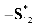
- in a case that N is greater than 2, S 12, S 34,


- Optionally, in a case that N is equal to 2, and S 12 = s 1, S 34= s 2,


- Optionally, in a case that N is equal to 4, and


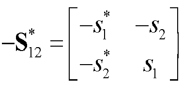


- Optionally, the first determining
module 801 is specifically configured to: - receive first indication information sent by a network-side device, where the first indication information is used to indicate the target encoded codeword; and
- determine the target encoded codeword based on the first indication information.
- Optionally, the first indication information includes at least one of the following:
- a transmit diversity order and a codeword matrix indicator; and
- codebook dimension indication information and a codeword matrix indicator.
- Optionally, a manner of carrying the first indication information includes one of the following:
- the first indication message is carried by downlink control information DCI;
- the first indication information is carried by a preamble sequence;
- the first indication information is carried by a signal sequence, where the signal sequence includes a signal sequence scrambled by a backscatter communication user equipment identity BSC UE ID or a random number related to BSC UE, or a signal sequence carrying a BSC UE ID; and
- the first indication information is carried by a media access control MAC control element CE.
- Optionally, the first determining
module 801 is specifically configured to determine the target encoded codeword based on capability information and/or channel state information of the terminal. - Optionally, the
diversity transmission apparatus 800 further includes:
a second sending module, configured to send second indication information to a network-side device, where the second indication information is used to indicate the target encoded codeword. - Optionally, the second indication information includes at least one of the following:
- a transmit diversity order and a codeword matrix indicator; and
- codebook dimension indication information and a codeword matrix indicator.
- Optionally, a manner of carrying the second indication information includes one of the following:
- the second indication information is carried by a MAC CE;
- the second indication information is carried by a preamble; and
- the second indication information is carried by a sequence.
- Optionally, the first determining
module 801 is specifically configured to determine the target encoded codeword in a case that a first target condition is met. - Optionally, the
diversity transmission apparatus 800 further includes:
a third sending module, configured to send first trigger information to a network-side device in a case that a first target condition is met, where the first trigger information is used to indicate to the network-side device that the terminal triggers diversity transmission. - Optionally, the first target condition includes at least one of the following:
- energy of a back-transmitted signal of the terminal is lower than a first threshold;
- the terminal is located at an edge of a cell;
- the number of negative acknowledgements NACKs sent by the terminal exceeds a second threshold; and
- energy of a downlink received signal is lower than a third threshold.
- Optionally, the
diversity transmission apparatus 800 further includes:
a first receiving module, configured to receive second trigger information sent by a network-side device, where the second trigger information is used to trigger diversity transmission of the terminal. - Optionally, a manner of carrying the second trigger information includes one of the following:
- the second trigger message is carried by DCI;
- the second trigger information is carried by a preamble sequence;
- the second trigger information is carried by a signal sequence, where the signal sequence includes a signal sequence scrambled by a BSC UE ID or a random number related to BSC UE, or a signal sequence carrying a BSC UE ID; and
- the second trigger information is carried by a MAC CE.
- Optionally, the
diversity transmission apparatus 800 further includes: - a second receiving module, configured to receive third indication information sent by a network-side device, where the third indication information is used to instruct the terminal to send measurement reference signals on M transmit antennas; and
- a fourth sending module, configured to send the measurement reference signals on the M transmit antennas based on the third indication information.
- Optionally, the fourth sending module is specifically configured to:
- separately send the measurement reference signals on the M transmit antennas at different times based on the third indication information; or
- separately send the measurement reference signals on the M transmit antennas at a same time based on the third indication information, where measurement reference signals sent on different transmit antennas have been scrambled by random numbers related to index information of the corresponding antennas.
- Optionally, the third indication information includes at least one of the following:
- information used to indicate a time or cycle of a measurement reference signal sent by the terminal on each of the M transmit antennas;
- information used to indicate a sequence of the measurement reference signal sent by the terminal on each of the M transmit antennas; and
- information used to indicate a frequency, a bandwidth, or a frequency shift of the measurement reference signal sent by the terminal on each of the M transmit antennas.
- Optionally, a manner of carrying the third indication information includes one of the following:
- the third indication information is carried by DCI;
- the third indication information is carried by a preamble sequence;
- the third indication information is carried by a signal sequence, where the signal sequence includes a signal sequence scrambled by a BSC UE ID or scrambled by a random number related to BSC UE, or a signal sequence carrying a BSC UE ID; and
- the third indication information is carried by a MAC CE.
- The diversity transmission apparatus in this embodiment of this application may be an electronic device, for example, an electronic device with an operating system, or may be a component in an electronic device, for example, an integrated circuit or a chip. The electronic device may be a terminal, or may be other devices than a terminal. For example, the terminal may include but is not limited to the foregoing illustrated type of the terminal 11. The other devices may be a server, a network attached storage (Network Attached Storage, NAS), and the like. This is not specifically limited in this embodiment of this application.
- The diversity transmission apparatus provided in this embodiment of this application can implement each process implemented by the method embodiment in
FIG. 2 , with the same technical effect achieved. To avoid repetition, details are not described herein again. -
FIG. 9 is a second schematic structural diagram of a diversity transmission apparatus according to an embodiment of this application. As shown inFIG. 9 , thediversity transmission apparatus 900 is applied to a network-side device and includes a second determiningmodule 901 and afirst sending module 902. - The second determining
module 901 is configured to determine a target encoded codeword; and - the
first sending module 902 is configured to send first indication information to a terminal, where the first indication information is used to indicate the target encoded codeword, where - the target encoded codeword meets a target encoding structure; the target encoded codeword is an encoding matrix with N×N dimensions; N= 2 k , and k is a positive integer; the target encoding structure includes a first basic element, a second basic element, a first generation element, and a second generation element; the first generation element is an opposite number of a conjugate operation result of the first basic element, and the second generation element is a conjugate operation result of the second basic element; and the first basic element, the second basic element, the first generation element, and the second generation element are complex numbers or block matrices.
- The diversity transmission apparatus provided in this embodiment of this application determines the target encoded codeword meeting the target encoding structure and sends the target encoded codeword to the terminal, to instruct the terminal to perform multi-antenna transmit diversity transmission by using the target encoded codeword, where the target encoded codeword is the encoding matrix with N×N dimensions; the target encoding structure includes the first basic element, the second basic element, the first generation element, and the second generation element; the first generation element is the opposite number of the conjugate operation result of the first basic element, and the second generation element is the conjugate operation result of the second basic element; and the first basic element, the second basic element, the first generation element, and the second generation element are complex numbers or block matrices. In comparison with the related art, the target encoded codeword designed based on the target encoding structure in this embodiment of this application can not only ensure a diversity gain, but also reduce types of reflection coefficients required on each antenna, that is, reduce types of load impedances required on each antenna, thereby reducing system implementation complexity and effectively reducing a probability of error detection.
- Optionally, the first indication information includes at least one of the following:
- a transmit diversity order and a codeword matrix indicator; and
- codebook dimension indication information and a codeword matrix indicator.
- Optionally, a manner of carrying the first indication information includes one of the following:
- the first indication message is carried by downlink control information DCI;
- the first indication information is carried by a preamble sequence;
- the first indication information is carried by a signal sequence, where the signal sequence includes a signal sequence scrambled by a backscatter communication user equipment identity BSC UE ID or a random number related to BSC UE, or a signal sequence carrying a BSC UE ID; and
- the first indication information is carried by a media access control MAC control element CE.
- Optionally, the second determining
module 901 is specifically configured to determine the target encoded codeword based on capability information and/or channel state information of the terminal in a case that a second target condition is met. - Optionally, the second target condition includes at least one of the following:
- energy of a back-transmitted signal of the terminal is lower than a first threshold;
- the terminal is located at an edge of a cell;
- the number of negative acknowledgements NACKs sent by the terminal exceeds a second threshold; and
- the network-side device receives first trigger information sent by the terminal, where the first trigger information is used to indicate to the network-side device that the terminal triggers diversity transmission.
- Optionally, a manner of carrying the first trigger information includes one of the following:
- the first trigger information is carried by a preamble sequence;
- the first trigger information is carried by a signal sequence, where the signal sequence includes a signal sequence scrambled by a BSC UE ID or a random number related to BSC UE, or a signal sequence carrying a BSC UE ID; and
- the first trigger information is carried by a MAC CE.
- Optionally, the
diversity transmission apparatus 900 further includes:
a fifth sending module, configured to send second trigger information to the terminal in a case that a second target condition is met, where the second trigger information is used to trigger diversity transmission of the terminal. - Optionally, a manner of carrying the second trigger information includes one of the following:
- the second trigger message is carried by DCI;
- the second trigger information is carried by a preamble sequence;
- the second trigger information is carried by a signal sequence, where the signal sequence includes a signal sequence scrambled by a BSC UE ID or a random number related to BSC UE, or a signal sequence carrying a BSC UE ID; and
- the second trigger information is carried by a MAC CE.
- Optionally, the
diversity transmission apparatus 900 further includes:
a sixth sending module, configured to send third indication information to the terminal in a case that a second target condition is met, where the third indication information is used to instruct the terminal to send measurement reference signals on M transmit antennas. - Optionally, the third indication information includes at least one of the following:
- information used to indicate a time or cycle of a measurement reference signal sent by the terminal on each of the M transmit antennas;
- information used to indicate a sequence of the measurement reference signal sent by the terminal on each of the M transmit antennas; and
- information used to indicate a frequency, a bandwidth, or a frequency shift of the measurement reference signal sent by the terminal on each of the M transmit antennas.
- The diversity transmission apparatus provided in this embodiment of this application can implement each process implemented by the method embodiment in
FIG. 3 , with the same technical effect achieved. To avoid repetition, details are not described herein again. - The diversity transmission apparatus in this embodiment of this application may be an electronic device, or may be a component such as an integrated circuit or a chip in an electronic device. The electronic device may be a terminal, or may be other devices than a terminal. For example, the electronic device may be a mobile phone, a tablet personal computer, a notebook computer, a palmtop computer, an in-vehicle electronic device, a mobile Internet device (Mobile Internet Device, MID), an augmented reality (augmented reality, AR) or virtual reality (virtual reality, VR) device, a robot, a wearable device, an ultra-mobile personal computer (ultra-mobile personal computer, UMPC), a netbook, a personal digital assistant (personal digital assistant, PDA), or the like; or the electronic device may be a server, a network attached storage (Network Attached Storage, NAS), a personal computer (personal computer, PC), a television (television, TV), a teller machine, a self-service machine, or the like. This is not specifically limited in this embodiment of this application.
- The diversity transmission apparatus in this embodiment of this application may be an apparatus with an operating system. The operating system may be an Android (Android) operating system, an iOS operating system, or other possible operating systems, and is not specifically limited in this embodiment of this application.
-
FIG. 10 is a schematic structural diagram of a communication device according to an embodiment of this application. As shown inFIG. 10 , thecommunication device 1000 includes aprocessor 1001 and amemory 1002. Thememory 1002 stores a program or instructions executable on theprocessor 1001. For example, when thecommunication device 1000 is a terminal, and the program or instructions are executed by theprocessor 1001, each step of the foregoing embodiment of the diversity transmission method is implemented, with the same technical effect achieved. When thecommunication device 1000 is a network-side device, and the program or instructions are executed by theprocessor 1001, each step of the foregoing embodiment of the diversity transmission method is implemented, with the same technical effect achieved. To avoid repetition, details are not described herein again. - An embodiment of this application further provides a terminal, including a processor and a communication interface. The processor is configured to determine a target encoded codeword; and the communication interface is configured to perform diversity transmission based on the target encoded codeword, where
the target encoded codeword meets a target encoding structure; the target encoded codeword is an encoding matrix with N×N dimensions; N= 2 k , and k is a positive integer; the target encoding structure includes a first basic element, a second basic element, a first generation element, and a second generation element; the first generation element is an opposite number of a conjugate operation result of the first basic element, and the second generation element is a conjugate operation result of the second basic element; and the first basic element, the second basic element, the first generation element, and the second generation element are complex numbers or block matrices. - The terminal embodiment corresponds to the foregoing terminal-side method embodiment, and each implementation process and implementation of the foregoing method embodiment can be applied to the terminal embodiment, with the same technical effect achieved.
-
FIG. 11 is a schematic structural diagram of a terminal according to an embodiment of this application. As shown inFIG. 11 , the terminal 1100 includes but is not limited to at least some components such as aradio frequency unit 1101, anetwork module 1102, an audio output unit 1103, aninput unit 1104, asensor 1105, adisplay unit 1106, auser input unit 1107, aninterface unit 1108, amemory 1109, and aprocessor 1110. - A person skilled in the art may understand that the terminal 1100 may further include a power supply (for example, a battery) supplying power to all components. The power supply may be logically connected to the
processor 1110 through a power management system. In this way, functions such as charge management, discharge management, and power consumption management are implemented by using the power management system. The terminal structure shown inFIG. 11 does not constitute a limitation on the terminal. The terminal may include more or fewer components than those shown in the figure, or some components are combined, or component arrangements are different. Details are not described herein again. - It should be understood that, in this embodiment of this application, the
input unit 1104 may include a graphics processing unit (Graphics Processing Unit, GPU) 11041 and amicrophone 11042. Thegraphics processing unit 11041 processes image data of a still picture or video obtained by an image capture apparatus (such as a camera) in a video capture mode or an image capture mode. Thedisplay unit 1106 may include adisplay panel 11061, and thedisplay panel 11061 may be configured in a form of a liquid crystal display, an organic light-emitting diode, or the like. Theuser input unit 1107 includes at least one of atouch panel 11071 andother input devices 11072. Thetouch panel 11071 is also referred to as a touchscreen. Thetouch panel 11071 may include two parts: a touch detection apparatus and a touch controller. Theother input devices 11072 may include but are not limited to a physical keyboard, a function button (such as a volume control button or a power button), a trackball, a mouse, and a joystick. Details are not described herein again. - In this embodiment of this application, after receiving downlink data from a network-side device, the
radio frequency unit 1101 may transmit the downlink data to theprocessor 1110 for processing. In addition, theradio frequency unit 1101 may send uplink data to the network-side device. Usually, theradio frequency unit 1101 includes but is not limited to an antenna, an amplifier, a transceiver, a coupler, a low noise amplifier, a duplexer, and the like. - The
memory 1109 may be configured to store software programs or instructions and various data. Thememory 1109 may primarily include a first storage area for storing programs or instructions and a second storage area for storing data. The first storage area may store an operating system, an application program or instructions required by at least one function (such as an audio play function and an image play function), and the like. In addition, thememory 1109 may include a volatile memory or a non-volatile memory, or thememory 1109 may include both a volatile memory and a non-volatile memory. The non-volatile memory may be a read-only memory (Read-Only Memory, ROM), a programmable read-only memory (Programmable ROM, PROM), an erasable programmable read-only memory (Erasable PROM, EPROM), an electrically erasable programmable read-only memory (Electrically EPROM, EEPROM), or a flash memory. The volatile memory may be a random access memory (Random Access Memory, RAM), a static random access memory (Static RAM, SRAM), a dynamic random access memory (Dynamic RAM, DRAM), a synchronous dynamic random access memory (Synchronous DRAM, SDRAM), a double data rate synchronous dynamic random access memory (Double Data rate SDRAM, DDR SDRAM), an enhanced synchronous dynamic random access memory (Enhanced SDRAM, ESDRAM), a synchlink dynamic random access memory (Synch Link DRAM, SLDRAM), and a direct rambus random access memory (Direct Rambus RAM, DRRAM). Thememory 1109 in this embodiment of this application includes but is not limited to these and any other suitable types of memories. - The
processor 1110 may include one or more processing units. Optionally, theprocessor 1110 integrates an application processor and a modem processor. The application processor mainly processes operations related to the operating system, a user interface, an application program, and the like. The modem processor mainly processes a wireless communication signal. For example, the modem processor is a baseband processor. It may be understood that the modem processor may alternatively be not integrated in theprocessor 1110. - The
processor 1110 is configured to determine a target encoded codeword; and - the
radio frequency unit 1101 is configured to perform diversity transmission based on the target encoded codeword, where - the target encoded codeword meets a target encoding structure; the target encoded codeword is an encoding matrix with N×N dimensions; N= 2 k , and k is a positive integer; the target encoding structure includes a first basic element, a second basic element, a first generation element, and a second generation element; the first generation element is an opposite number of a conjugate operation result of the first basic element, and the second generation element is a conjugate operation result of the second basic element; and the first basic element, the second basic element, the first generation element, and the second generation element are complex numbers or block matrices.
- The terminal provided in this embodiment of this application determines the target encoded codeword meeting the target encoding structure and performs multi-antenna transmit diversity transmission by using the target encoded codeword, where the target encoded codeword is the encoding matrix with N×N dimensions; the target encoding structure includes the first basic element, the second basic element, the first generation element, and the second generation element; the first generation element is the opposite number of the conjugate operation result of the first basic element, and the second generation element is the conjugate operation result of the second basic element; and the first basic element, the second basic element, the first generation element, and the second generation element are complex numbers or block matrices. In comparison with the related art, the target encoded codeword designed based on the target encoding structure in the embodiments of this application can not only ensure a diversity gain, but also reduce types of reflection coefficients required on each antenna, that is, reduce types of load impedances required on each antenna, thereby reducing system implementation complexity and effectively reducing a probability of error detection.
- An embodiment of this application further provides a network-side device, including a processor and a communication interface. The processor is configured to determine a target encoded codeword in a case that a second target condition is met; and the communication interface is configured to send first indication information to a terminal, where the first indication information is used to indicate the target encoded codeword, where
- the target encoded codeword meets a target encoding structure; the target encoded codeword is an encoding matrix with N×N dimensions; N= 2 k , and k is a positive integer;
- the target encoding structure includes a first basic element, a second basic element, a first generation element, and a second generation element; the first generation element is an opposite number of a conjugate operation result of the first basic element, and the second generation element is a conjugate operation result of the second basic element; and the first basic element, the second basic element, the first generation element, and the second generation element are complex numbers or block matrices.
- The network-side device embodiment corresponds to the foregoing method embodiment of the network-side device, and each implementation process and implementation of the foregoing method embodiment can be applied to the network-side device embodiment, with the same technical effect achieved.
-
FIG. 12 is a schematic structural diagram of a network-side device according to an embodiment of this application. As shown inFIG. 12 , the network-side device 1200 includes anantenna 1201, aradio frequency apparatus 1202, abaseband apparatus 1203, aprocessor 1204, and amemory 1205. Theantenna 1201 is connected to theradio frequency apparatus 1202. In an uplink direction, theradio frequency apparatus 1202 receives information by using theantenna 1201, and sends the received information to thebaseband apparatus 1203 for processing. In a downlink direction, thebaseband apparatus 1203 processes to-be-sent information, and sends the information to theradio frequency apparatus 1202; and theradio frequency apparatus 1202 processes the received information and then sends the information out by using theantenna 1201. - The method performed by the network-side device in the foregoing embodiment may be implemented in the
baseband apparatus 1203. Thebaseband apparatus 1203 includes a baseband processor. - The
baseband apparatus 1203 may include, for example, at least one baseband unit, where a plurality of chips are disposed on the baseband unit. As shown inFIG. 12 , one of the chips is, for example, the baseband processor, connected to thememory 1205 by using a bus interface, to invoke a program in thememory 1205 to perform the operation of the network-side device shown in the foregoing method embodiment. - The network-side device may further include a
network interface 1206, where the interface is, for example, a common public radio interface (common public radio interface, CPRI). - Specifically, the network-
side device 1200 in this embodiment of the present invention further includes a program or instructions stored in thememory 1205 and executable on theprocessor 1204. When theprocessor 1204 invokes the program or instructions in thememory 1205, the method performed by each module shown inFIG. 7 is performed, with the same technical effect achieved. To avoid repetition, details are not described herein again. - An embodiment of this application further provides a diversity transmission system, including a terminal and a network-side device. The terminal may be configured to perform the steps of the foregoing diversity transmission method. The network-side device may be configured to perform the steps of the foregoing diversity transmission method.
- An embodiment of this application further provides a readable storage medium. The readable storage medium may be volatile or non-volatile. The readable storage medium stores a program or instructions. When the program or instructions are executed by a processor, each process of the foregoing embodiment of the diversity transmission method is implemented, with the same technical effect achieved. To avoid repetition, details are not described herein again.
- The processor is a processor in the terminal in the foregoing embodiment. The readable storage medium includes a computer-readable storage medium, such as a computer read-only memory ROM, a random access memory RAM, a magnetic disk, or an optical disc.
- In addition, an embodiment of this application provides a chip. The chip includes a processor and a communication interface. The communication interface is coupled to the processor. The processor is configured to run a program or instructions to implement each process of the embodiment of the diversity transmission method, with the same technical effect achieved. To avoid repetition, details are not described herein again.
- It should be understood that the chip provided in this embodiment of this application may also be referred to as a system-level chip, a system chip, a chip system, a system-on-chip, or the like.
- In addition, an embodiment of this application provides a computer program or program product. The computer program or program product is stored in a storage medium. The computer program or program product is executed by at least one processor to implement each process of the foregoing embodiment of the diversity transmission method, with the same technical effect achieved. To avoid repetition, details are not described herein again.
- It should be noted that in this specification, the term "comprise", "include", or any of their variants are intended to cover a non-exclusive inclusion, so that a process, a method, an article, or an apparatus that includes a list of elements not only includes those elements but also includes other elements that are not expressly listed, or further includes elements inherent to such process, method, article, or apparatus. In absence of more constraints, an element preceded by "includes a ..." does not preclude existence of other identical elements in the process, method, article, or apparatus that includes the element. In addition, it should be noted that the scope of the method and apparatus in the implementations of this application is not limited to performing the functions in an order shown or discussed, and may further include performing the functions in a substantially simultaneous manner or in a reverse order depending on the functions used. For example, the method described may be performed in an order different from that described, and various steps may be added, omitted, or combined. In addition, features described with reference to some examples may be combined in other examples.
- According to the foregoing description of the implementations, a person skilled in the art may clearly understand that the methods in the foregoing embodiments may be implemented by using software in combination with a necessary general hardware platform, and certainly may alternatively be implemented by using hardware. However, in most cases, the former is a preferred implementation. Based on such an understanding, the technical solutions of this application essentially or the part contributing to the prior art may be implemented in a form of a computer software product. The computer software product is stored in a storage medium (such as a ROM/RAM, a magnetic disk, or an optical disc), and includes several instructions for instructing a terminal (which may be a mobile phone, a computer, a server, an air conditioner, a network device, or the like) to perform the methods described in the embodiments of this application.
- The foregoing describes the embodiments of this application with reference to the accompanying drawings. However, this application is not limited to the foregoing specific embodiments. The foregoing specific embodiments are merely illustrative rather than restrictive. Inspired by this application, a person of ordinary skill in the art may develop many other manners without departing from principles of this application and the protection scope of the claims, and all such manners fall within the protection scope of this application.
Claims (35)
- A diversity transmission method, comprising:determining, by a terminal, a target encoded codeword; andperforming, by the terminal, diversity transmission based on the target encoded codeword, whereinthe target encoded codeword meets a target encoding structure; the target encoded codeword is an encoding matrix with N×N dimensions; N= 2 k , and k is a positive integer; the target encoding structure comprises a first basic element, a second basic element, a first generation element, and a second generation element; the first generation element is an opposite number of a conjugate operation result of the first basic element, and the second generation element is a conjugate operation result of the second basic element; and the first basic element, the second basic element, the first generation element, and the second generation element are complex numbers or block matrices.
- The diversity transmission method according to claim 1, wherein the target encoding structure is represented by S ; and

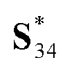


 in a case that N is equal to 2, S 12, S 34,


 in a case that N is greater than 2, S 12, S 34,


- The diversity transmission method according to claim 2, whereinin a case that N is equal to 4, and


 wherein elements in S 4 are all complex numbers,


- The diversity transmission method according to claim 1, wherein the determining, by a terminal, a target encoded codeword comprises:receiving, by the terminal, first indication information sent by a network-side device, wherein the first indication information is used to indicate the target encoded codeword; anddetermining, by the terminal, the target encoded codeword based on the first indication information.
- The diversity transmission method according to claim 4, wherein the first indication information comprises at least one of the following:a transmit diversity order and a codeword matrix indicator; andcodebook dimension indication information and a codeword matrix indicator.
- The diversity transmission method according to claim 4 or 5, wherein a manner of carrying the first indication information comprises one of the following:the first indication message is carried by downlink control information DCI;the first indication information is carried by a preamble sequence;the first indication information is carried by a signal sequence, wherein the signal sequence comprises a signal sequence scrambled by a backscatter communication user equipment identity BSC UE ID or a random number related to BSC UE, or a signal sequence carrying a BSC UE ID; andthe first indication information is carried by a media access control MAC control element CE.
- The diversity transmission method according to claim 1, wherein the determining, by a terminal, a target encoded codeword comprises: determining, by the terminal, the target encoded codeword based on capability information and/or channel state information of the terminal.
- The diversity transmission method according to claim 7, wherein the method further comprises:
sending, by the terminal, second indication information to a network-side device, wherein the second indication information is used to indicate the target encoded codeword. - The diversity transmission method according to claim 8, wherein the second indication information comprises at least one of the following:a transmit diversity order and a codeword matrix indicator; andcodebook dimension indication information and a codeword matrix indicator.
- The diversity transmission method according to claim 8 or 9, wherein a manner of carrying the second indication information comprises one of the following:the second indication information is carried by a MAC CE;the second indication information is carried by a preamble; andthe second indication information is carried by a sequence.
- The diversity transmission method according to claim 7, wherein the determining, by a terminal, a target encoded codeword comprises:
in a case that a first target condition is met, determining, by the terminal, the target encoded codeword. - The diversity transmission method according to claim 1, wherein the method further comprises:
in a case that a first target condition is met, sending, by the terminal, first trigger information to a network-side device, wherein the first trigger information is used to indicate to the network-side device that the terminal triggers diversity transmission. - The diversity transmission method according to claim 12, wherein a manner of carrying the first trigger information comprises one of the following:the first trigger information is carried by a preamble sequence;the first trigger information is carried by a signal sequence, wherein the signal sequence comprises a signal sequence scrambled by a BSC UE ID or a random number related to BSC UE, or a signal sequence carrying a BSC UE ID; andthe first trigger information is carried by a MAC CE.
- The diversity transmission method according to claim 11 or 12, wherein the first target condition comprises at least one of the following:energy of a back-transmitted signal of the terminal is lower than a first threshold;the terminal is located at an edge of a cell;the number of negative acknowledgements NACKs sent by the terminal exceeds a second threshold; andenergy of a downlink received signal is lower than a third threshold.
- The diversity transmission method according to claim 1, wherein the method further comprises:
receiving, by the terminal, second trigger information sent by a network-side device, wherein the second trigger information is used to trigger diversity transmission of the terminal. - The diversity transmission method according to claim 15, wherein a manner of carrying the second trigger information comprises one of the following:the second trigger message is carried by DCI;the second trigger information is carried by a preamble sequence;the second trigger information is carried by a signal sequence, wherein the signal sequence comprises a signal sequence scrambled by a BSC UE ID or a random number related to BSC UE, or a signal sequence carrying a BSC UE ID; andthe second trigger information is carried by a MAC CE.
- The diversity transmission method according to claim 1, wherein the method further comprises:receiving, by the terminal, third indication information sent by a network-side device, wherein the third indication information is used to instruct the terminal to send measurement reference signals on M transmit antennas; andsending, by the terminal, the measurement reference signals on the M transmit antennas based on the third indication information.
- The diversity transmission method according to claim 17, wherein the sending, by the terminal, the measurement reference signals on the M transmit antennas based on the third indication information comprises:separately sending, by the terminal, the measurement reference signals on the M transmit antennas at different times based on the third indication information; orseparately sending, by the terminal, the measurement reference signals on the M transmit antennas at a same time based on the third indication information, wherein measurement reference signals sent on different transmit antennas have been scrambled by random numbers related to index information of the corresponding antennas.
- The diversity transmission method according to claim 17, wherein the third indication information comprises at least one of the following:information used to indicate a time or cycle of a measurement reference signal sent by the terminal on each of the M transmit antennas;information used to indicate a sequence of the measurement reference signal sent by the terminal on each of the M transmit antennas; andinformation used to indicate a frequency, a bandwidth, or a frequency shift of the measurement reference signal sent by the terminal on each of the M transmit antennas.
- The diversity transmission method according to any one of claims 17 to 19, wherein a manner of carrying the third indication information comprises one of the following:the third indication information is carried by DCI;the third indication information is carried by a preamble sequence;the third indication information is carried by a signal sequence, wherein the signal sequence comprises a signal sequence scrambled by a BSC UE ID or scrambled by a random number related to BSC UE, or a signal sequence carrying a BSC UE ID; andthe third indication information is carried by a MAC CE.
- A diversity transmission method, comprising:determining, by a network-side device, a target encoded codeword; andsending, by the network-side device, first indication information to a terminal, wherein the first indication information is used to indicate the target encoded codeword, whereinthe target encoded codeword meets a target encoding structure; the target encoded codeword is an encoding matrix with N×N dimensions; N= 2 k , and k is a positive integer; the target encoding structure comprises a first basic element, a second basic element, a first generation element, and a second generation element; the first generation element is an opposite number of a conjugate operation result of the first basic element, and the second generation element is a conjugate operation result of the second basic element; and the first basic element, the second basic element, the first generation element, and the second generation element are complex numbers or block matrices.
- The diversity transmission method according to claim 21, wherein the first indication information comprises at least one of the following:a transmit diversity order and a codeword matrix indicator; andcodebook dimension indication information and a codeword matrix indicator.
- The diversity transmission method according to claim 21 or 22, wherein a manner of carrying the first indication information comprises one of the following:the first indication message is carried by downlink control information DCI;the first indication information is carried by a preamble sequence;the first indication information is carried by a signal sequence, wherein the signal sequence comprises a signal sequence scrambled by a backscatter communication user equipment identity BSC UE ID or a random number related to BSC UE, or a signal sequence carrying a BSC UE ID; andthe first indication information is carried by a media access control MAC control element CE.
- The diversity transmission method according to claim 21, wherein the determining, by a network-side device, a target encoded codeword comprises:
in a case that a second target condition is met, determining, by the network-side device, the target encoded codeword based on capability information and/or channel state information of the terminal. - The diversity transmission method according to claim 24, wherein the second target condition comprises at least one of the following:energy of a back-transmitted signal of the terminal is lower than a first threshold;the terminal is located at an edge of a cell;the number of negative acknowledgements NACKs sent by the terminal exceeds a second threshold; andthe network-side device receives first trigger information sent by the terminal, wherein the first trigger information is used to indicate to the network-side device that the terminal triggers diversity transmission.
- The diversity transmission method according to claim 25, wherein a manner of carrying the first trigger information comprises one of the following:the first trigger information is carried by a preamble sequence;the first trigger information is carried by a signal sequence, wherein the signal sequence comprises a signal sequence scrambled by a BSC UE ID or a random number related to BSC UE, or a signal sequence carrying a BSC UE ID; andthe first trigger information is carried by a MAC CE.
- The diversity transmission method according to claim 21, wherein the method further comprises:
in a case that a second target condition is met, sending, by the network-side device, second trigger information to the terminal, wherein the second trigger information is used to trigger diversity transmission of the terminal. - The diversity transmission method according to claim 27, wherein a manner of carrying the second trigger information comprises one of the following:the second trigger message is carried by DCI;the second trigger information is carried by a preamble sequence;the second trigger information is carried by a signal sequence, wherein the signal sequence comprises a signal sequence scrambled by a BSC UE ID or a random number related to BSC UE, or a signal sequence carrying a BSC UE ID; andthe second trigger information is carried by a MAC CE.
- The diversity transmission method according to claim 21, wherein the method further comprises:
in a case that a second target condition is met, sending, by the network-side device, third indication information to the terminal, wherein the third indication information is used to instruct the terminal to send measurement reference signals on M transmit antennas. - The diversity transmission method according to claim 29, wherein the third indication information comprises at least one of the following:information used to indicate a time or cycle of a measurement reference signal sent by the terminal on each of the M transmit antennas;information used to indicate a sequence of the measurement reference signal sent by the terminal on each of the M transmit antennas; andinformation used to indicate a frequency, a bandwidth, or a frequency shift of the measurement reference signal sent by the terminal on each of the M transmit antennas.
- A diversity transmission apparatus, applied to a terminal and comprising:a first determining module, configured to determine a target encoded codeword; anda transmission module, configured to perform diversity transmission based on the target encoded codeword, whereinthe target encoded codeword meets a target encoding structure; the target encoded codeword is an encoding matrix with N×N dimensions; N= 2 k , and k is a positive integer; the target encoding structure comprises a first basic element, a second basic element, a first generation element, and a second generation element; the first generation element is an opposite number of a conjugate operation result of the first basic element, and the second generation element is a conjugate operation result of the second basic element; and the first basic element, the second basic element, the first generation element, and the second generation element are complex numbers or block matrices.
- A diversity transmission apparatus, applied to a network-side device and comprising:a second determining module, configured to determine a target encoded codeword; anda first sending module, configured to send first indication information to a terminal, wherein the first indication information is used to indicate the target encoded codeword, whereinthe target encoded codeword meets a target encoding structure; the target encoded codeword is an encoding matrix with N×N dimensions; N= 2 k , and k is a positive integer; the target encoding structure comprises a first basic element, a second basic element, a first generation element, and a second generation element; the first generation element is an opposite number of a conjugate operation result of the first basic element, and the second generation element is a conjugate operation result of the second basic element; and the first basic element, the second basic element, the first generation element, and the second generation element are complex numbers or block matrices.
- A terminal, comprising a processor and a memory, wherein the memory stores a program or instructions executable on the processor, and when the program or instructions are executed by the processor, the steps of the diversity transmission method according to any one of claims 1 to 20 are implemented.
- A network-side device, comprising a processor and a memory, wherein the memory stores a program or instructions executable on the processor, and when the program or instructions are executed by the processor, the steps of the diversity transmission method according to any one of claims 21 to 30 are implemented.
- A readable storage medium, wherein the readable storage medium stores a program or instructions, and when the program or instructions are executed by a processor, the steps of the diversity transmission method according to any one of claims 1 to 20 are implemented, or the steps of the diversity transmission method according to any one of claims 21 to 30 are implemented.
Applications Claiming Priority (2)
| Application Number | Priority Date | Filing Date | Title |
|---|---|---|---|
| CN202111484934.3A CN116248224B (en) | 2021-12-07 | 2021-12-07 | Diversity transmission method, terminal and network side equipment |
| PCT/CN2022/136286 WO2023103912A1 (en) | 2021-12-07 | 2022-12-02 | Diversity transmission method, terminal and network-side device |
Publications (2)
| Publication Number | Publication Date |
|---|---|
| EP4447345A1 true EP4447345A1 (en) | 2024-10-16 |
| EP4447345A4 EP4447345A4 (en) | 2025-06-04 |
Family
ID=86629987
Family Applications (1)
| Application Number | Title | Priority Date | Filing Date |
|---|---|---|---|
| EP22903334.5A Pending EP4447345A4 (en) | 2021-12-07 | 2022-12-02 | Diversity transmission method, terminal and network-side device |
Country Status (4)
| Country | Link |
|---|---|
| US (1) | US12562783B2 (en) |
| EP (1) | EP4447345A4 (en) |
| CN (1) | CN116248224B (en) |
| WO (1) | WO2023103912A1 (en) |
Families Citing this family (1)
| Publication number | Priority date | Publication date | Assignee | Title |
|---|---|---|---|---|
| US20240250852A1 (en) * | 2023-01-24 | 2024-07-25 | Qualcomm Incorporated | Multi-antenna reader channel state information acquisition |
Family Cites Families (15)
| Publication number | Priority date | Publication date | Assignee | Title |
|---|---|---|---|---|
| DE60134641D1 (en) * | 2001-08-13 | 2008-08-14 | Motorola Inc | Wireless communication with broadcasting diversity |
| JP5123295B2 (en) * | 2006-06-08 | 2013-01-23 | コーニンクレッカ フィリップス エレクトロニクス エヌ ヴィ | Method and apparatus for space / time / frequency coding |
| US8027407B2 (en) * | 2006-11-06 | 2011-09-27 | Ntt Docomo, Inc. | Method and apparatus for asynchronous space-time coded transmission from multiple base stations over wireless radio networks |
| EP2181517A4 (en) * | 2007-03-30 | 2017-04-19 | Telefonaktiebolaget LM Ericsson (publ) | Method and device for interference suppression in user terminal |
| US7991063B2 (en) * | 2007-06-06 | 2011-08-02 | Samsung Electronics Co., Ltd | Transmission symbols mapping for antenna diversity |
| KR101397039B1 (en) * | 2007-08-14 | 2014-05-20 | 엘지전자 주식회사 | Signal Transmission Method Using CDM Against The Effect Of Channel Estimation Error in Transmit Diversity System |
| CN101494488B (en) * | 2008-01-23 | 2013-06-05 | 电信科学技术研究院 | Method and apparatus for transmitting data through polarization antenna |
| US20100067512A1 (en) * | 2008-09-17 | 2010-03-18 | Samsung Electronics Co., Ltd. | Uplink transmit diversity schemes with 4 antenna ports |
| US8576775B2 (en) * | 2009-04-27 | 2013-11-05 | Blackberry Limited | Hybrid-QRD-SIC and imbalanced MCS system and method for MIMO |
| CN108781100B (en) * | 2016-03-10 | 2021-06-22 | 华为技术有限公司 | Transmission diversity method, equipment and system |
| CN108288987B (en) * | 2017-01-07 | 2021-10-01 | 华为技术有限公司 | A method, terminal and base station for transmit diversity |
| CN109309518B (en) * | 2017-07-26 | 2021-09-07 | 华为技术有限公司 | Method, apparatus and system for data transmission |
| US10992420B2 (en) * | 2017-08-11 | 2021-04-27 | Telefonaktiebolaget Lm Ericsson (Publ) | Selective symbol repetition for SFBC on sPDCCH |
| CN109842463A (en) * | 2017-11-27 | 2019-06-04 | 深圳超级数据链技术有限公司 | Data transmission method, device, storage medium and processor |
| US10999848B2 (en) * | 2018-10-01 | 2021-05-04 | Research & Business Foundation Sungkyunkwan University | Sparse-coded ambient backscatter communication method and system |
-
2021
- 2021-12-07 CN CN202111484934.3A patent/CN116248224B/en active Active
-
2022
- 2022-12-02 WO PCT/CN2022/136286 patent/WO2023103912A1/en not_active Ceased
- 2022-12-02 EP EP22903334.5A patent/EP4447345A4/en active Pending
-
2024
- 2024-06-07 US US18/737,896 patent/US12562783B2/en active Active
Also Published As
| Publication number | Publication date |
|---|---|
| EP4447345A4 (en) | 2025-06-04 |
| US20240333342A1 (en) | 2024-10-03 |
| WO2023103912A1 (en) | 2023-06-15 |
| CN116248224A (en) | 2023-06-09 |
| CN116248224B (en) | 2025-09-19 |
| US12562783B2 (en) | 2026-02-24 |
Similar Documents
| Publication | Publication Date | Title |
|---|---|---|
| EP4258786B1 (en) | Pusch scheduling transmission methods, terminal and network side device | |
| EP4468617A1 (en) | Coding method, device and readable storage medium | |
| US20240388927A1 (en) | Information Transmission Method, Terminal, and Network Side Device | |
| US11616606B2 (en) | Cell edge reliability improvements | |
| US20260129651A1 (en) | Beam indication method, network side device, and terminal | |
| US12562783B2 (en) | Diversity transmission method, terminal, and network-side device | |
| CN116963285A (en) | Information receiving method, information sending method, device and equipment | |
| US20260088962A1 (en) | Channel state information transmission method and apparatus, terminal, and network-side device | |
| US20250261202A1 (en) | Method for common pucch transmission with repetitions, terminal, and network-side device | |
| US20250343655A1 (en) | Phase tracking reference signal transmission method and apparatus, terminal, and network-side device | |
| US20240422755A1 (en) | Transmission method and apparatus, terminal, and storage medium | |
| US20240372650A1 (en) | Coding method and apparatus and readable storage medium | |
| US20250055652A1 (en) | Beam information determination method, and terminal, and network-side device | |
| WO2023125423A1 (en) | Coding method, device, and readable storage medium | |
| EP4459916A1 (en) | Decoding method and device and readable storage medium | |
| CN117279091A (en) | Beam pointing method, device and terminal | |
| CN116938311A (en) | Information transmission method and device and communication equipment | |
| US20210028835A1 (en) | Group MIMO | |
| US20260101343A1 (en) | Method and apparatus of uplink transmission | |
| US20240413949A1 (en) | Demodulation reference signal information determining method and indication method, and related device | |
| US20250379618A1 (en) | Multi-antenna transmit diversity indication method, terminal, and network side device | |
| US20250358829A1 (en) | Method and apparatus for determining size of dci, method and apparatus for sending dci, and related device | |
| US20250133459A1 (en) | Parameter determining method, terminal, and network side device | |
| US20260128783A1 (en) | Control methods for receiver antenna selection and interference cancelation and apparatus thereof | |
| WO2024032293A1 (en) | Wireless communication method, user equipment, and base station background of disclosure |
Legal Events
| Date | Code | Title | Description |
|---|---|---|---|
| STAA | Information on the status of an ep patent application or granted ep patent |
Free format text: STATUS: THE INTERNATIONAL PUBLICATION HAS BEEN MADE |
|
| PUAI | Public reference made under article 153(3) epc to a published international application that has entered the european phase |
Free format text: ORIGINAL CODE: 0009012 |
|
| STAA | Information on the status of an ep patent application or granted ep patent |
Free format text: STATUS: REQUEST FOR EXAMINATION WAS MADE |
|
| 17P | Request for examination filed |
Effective date: 20240704 |
|
| AK | Designated contracting states |
Kind code of ref document: A1 Designated state(s): AL AT BE BG CH CY CZ DE DK EE ES FI FR GB GR HR HU IE IS IT LI LT LU LV MC ME MK MT NL NO PL PT RO RS SE SI SK SM TR |
|
| RIC1 | Information provided on ipc code assigned before grant |
Ipc: H04B 7/06 20060101ALI20250205BHEP Ipc: H04B 5/45 20240101ALI20250205BHEP Ipc: H04L 1/06 20060101ALI20250205BHEP Ipc: H04L 1/00 20060101AFI20250205BHEP |
|
| DAV | Request for validation of the european patent (deleted) | ||
| DAX | Request for extension of the european patent (deleted) | ||
| A4 | Supplementary search report drawn up and despatched |
Effective date: 20250507 |
|
| RIC1 | Information provided on ipc code assigned before grant |
Ipc: H04B 7/06 20060101ALI20250429BHEP Ipc: H04B 5/45 20240101ALI20250429BHEP Ipc: H04L 1/06 20060101ALI20250429BHEP Ipc: H04L 1/00 20060101AFI20250429BHEP |