EP4447262A1 - Isolated solid-state active pre-charger - Google Patents
Isolated solid-state active pre-charger Download PDFInfo
- Publication number
- EP4447262A1 EP4447262A1 EP24164655.3A EP24164655A EP4447262A1 EP 4447262 A1 EP4447262 A1 EP 4447262A1 EP 24164655 A EP24164655 A EP 24164655A EP 4447262 A1 EP4447262 A1 EP 4447262A1
- Authority
- EP
- European Patent Office
- Prior art keywords
- high voltage
- voltage battery
- circuit
- charge
- battery
- Prior art date
- Legal status (The legal status is an assumption and is not a legal conclusion. Google has not performed a legal analysis and makes no representation as to the accuracy of the status listed.)
- Pending
Links
Images


Classifications
-
- B—PERFORMING OPERATIONS; TRANSPORTING
- B60—VEHICLES IN GENERAL
- B60L—PROPULSION OF ELECTRICALLY-PROPELLED VEHICLES; SUPPLYING ELECTRIC POWER FOR AUXILIARY EQUIPMENT OF ELECTRICALLY-PROPELLED VEHICLES; ELECTRODYNAMIC BRAKE SYSTEMS FOR VEHICLES IN GENERAL; MAGNETIC SUSPENSION OR LEVITATION FOR VEHICLES; MONITORING OPERATING VARIABLES OF ELECTRICALLY-PROPELLED VEHICLES; ELECTRIC SAFETY DEVICES FOR ELECTRICALLY-PROPELLED VEHICLES
- B60L3/00—Electric devices on electrically-propelled vehicles for safety purposes; Monitoring operating variables, e.g. speed, deceleration or energy consumption
- B60L3/0092—Electric devices on electrically-propelled vehicles for safety purposes; Monitoring operating variables, e.g. speed, deceleration or energy consumption with use of redundant elements for safety purposes
-
- H—ELECTRICITY
- H02—GENERATION; CONVERSION OR DISTRIBUTION OF ELECTRIC POWER
- H02M—APPARATUS FOR CONVERSION BETWEEN AC AND AC, BETWEEN AC AND DC, OR BETWEEN DC AND DC, AND FOR USE WITH MAINS OR SIMILAR POWER SUPPLY SYSTEMS; CONVERSION OF DC OR AC INPUT POWER INTO SURGE OUTPUT POWER; CONTROL OR REGULATION THEREOF
- H02M3/00—Conversion of DC power input into DC power output
- H02M3/22—Conversion of DC power input into DC power output with intermediate conversion into AC
- H02M3/24—Conversion of DC power input into DC power output with intermediate conversion into AC by static converters
- H02M3/28—Conversion of DC power input into DC power output with intermediate conversion into AC by static converters using discharge tubes with control electrode or semiconductor devices with control electrode to produce the intermediate AC
- H02M3/325—Conversion of DC power input into DC power output with intermediate conversion into AC by static converters using discharge tubes with control electrode or semiconductor devices with control electrode to produce the intermediate AC using devices of a triode or a transistor type requiring continuous application of a control signal
- H02M3/335—Conversion of DC power input into DC power output with intermediate conversion into AC by static converters using discharge tubes with control electrode or semiconductor devices with control electrode to produce the intermediate AC using devices of a triode or a transistor type requiring continuous application of a control signal using semiconductor devices only
- H02M3/33569—Conversion of DC power input into DC power output with intermediate conversion into AC by static converters using discharge tubes with control electrode or semiconductor devices with control electrode to produce the intermediate AC using devices of a triode or a transistor type requiring continuous application of a control signal using semiconductor devices only having several active switching elements
-
- B—PERFORMING OPERATIONS; TRANSPORTING
- B60—VEHICLES IN GENERAL
- B60L—PROPULSION OF ELECTRICALLY-PROPELLED VEHICLES; SUPPLYING ELECTRIC POWER FOR AUXILIARY EQUIPMENT OF ELECTRICALLY-PROPELLED VEHICLES; ELECTRODYNAMIC BRAKE SYSTEMS FOR VEHICLES IN GENERAL; MAGNETIC SUSPENSION OR LEVITATION FOR VEHICLES; MONITORING OPERATING VARIABLES OF ELECTRICALLY-PROPELLED VEHICLES; ELECTRIC SAFETY DEVICES FOR ELECTRICALLY-PROPELLED VEHICLES
- B60L3/00—Electric devices on electrically-propelled vehicles for safety purposes; Monitoring operating variables, e.g. speed, deceleration or energy consumption
- B60L3/0023—Detecting, eliminating, remedying or compensating for drive train abnormalities, e.g. failures within the drive train
- B60L3/0046—Detecting, eliminating, remedying or compensating for drive train abnormalities, e.g. failures within the drive train relating to electric energy storage systems, e.g. batteries or capacitors
-
- B—PERFORMING OPERATIONS; TRANSPORTING
- B60—VEHICLES IN GENERAL
- B60L—PROPULSION OF ELECTRICALLY-PROPELLED VEHICLES; SUPPLYING ELECTRIC POWER FOR AUXILIARY EQUIPMENT OF ELECTRICALLY-PROPELLED VEHICLES; ELECTRODYNAMIC BRAKE SYSTEMS FOR VEHICLES IN GENERAL; MAGNETIC SUSPENSION OR LEVITATION FOR VEHICLES; MONITORING OPERATING VARIABLES OF ELECTRICALLY-PROPELLED VEHICLES; ELECTRIC SAFETY DEVICES FOR ELECTRICALLY-PROPELLED VEHICLES
- B60L53/00—Methods of charging batteries, specially adapted for electric vehicles; Charging stations or on-board charging equipment therefor; Exchange of energy storage elements in electric vehicles
- B60L53/20—Methods of charging batteries, specially adapted for electric vehicles; Charging stations or on-board charging equipment therefor; Exchange of energy storage elements in electric vehicles characterised by converters located in the vehicle
-
- B—PERFORMING OPERATIONS; TRANSPORTING
- B60—VEHICLES IN GENERAL
- B60L—PROPULSION OF ELECTRICALLY-PROPELLED VEHICLES; SUPPLYING ELECTRIC POWER FOR AUXILIARY EQUIPMENT OF ELECTRICALLY-PROPELLED VEHICLES; ELECTRODYNAMIC BRAKE SYSTEMS FOR VEHICLES IN GENERAL; MAGNETIC SUSPENSION OR LEVITATION FOR VEHICLES; MONITORING OPERATING VARIABLES OF ELECTRICALLY-PROPELLED VEHICLES; ELECTRIC SAFETY DEVICES FOR ELECTRICALLY-PROPELLED VEHICLES
- B60L58/00—Methods or circuit arrangements for monitoring or controlling batteries or fuel cells, specially adapted for electric vehicles
- B60L58/10—Methods or circuit arrangements for monitoring or controlling batteries or fuel cells, specially adapted for electric vehicles for monitoring or controlling batteries
- B60L58/12—Methods or circuit arrangements for monitoring or controlling batteries or fuel cells, specially adapted for electric vehicles for monitoring or controlling batteries responding to state of charge [SoC]
-
- H—ELECTRICITY
- H02—GENERATION; CONVERSION OR DISTRIBUTION OF ELECTRIC POWER
- H02J—ELECTRIC POWER NETWORKS; CIRCUIT ARRANGEMENTS OR SYSTEMS FOR SUPPLYING OR DISTRIBUTING ELECTRIC POWER; SYSTEMS FOR STORING ELECTRIC ENERGY
- H02J7/00—Circuit arrangements for charging or discharging batteries or for supplying loads from batteries
- H02J7/34—Parallel operation in networks using both storage and other DC sources, e.g. providing buffering
- H02J7/345—Parallel operation in networks using both storage and other DC sources, e.g. providing buffering using capacitors as storage or buffering devices
-
- H—ELECTRICITY
- H02—GENERATION; CONVERSION OR DISTRIBUTION OF ELECTRIC POWER
- H02J—ELECTRIC POWER NETWORKS; CIRCUIT ARRANGEMENTS OR SYSTEMS FOR SUPPLYING OR DISTRIBUTING ELECTRIC POWER; SYSTEMS FOR STORING ELECTRIC ENERGY
- H02J7/00—Circuit arrangements for charging or discharging batteries or for supplying loads from batteries
- H02J7/90—Regulation of charging or discharging current or voltage
-
- H—ELECTRICITY
- H02—GENERATION; CONVERSION OR DISTRIBUTION OF ELECTRIC POWER
- H02M—APPARATUS FOR CONVERSION BETWEEN AC AND AC, BETWEEN AC AND DC, OR BETWEEN DC AND DC, AND FOR USE WITH MAINS OR SIMILAR POWER SUPPLY SYSTEMS; CONVERSION OF DC OR AC INPUT POWER INTO SURGE OUTPUT POWER; CONTROL OR REGULATION THEREOF
- H02M1/00—Details of apparatus for conversion
- H02M1/0003—Details of control, feedback or regulation circuits
- H02M1/0009—Devices or circuits for detecting current in a converter
-
- H—ELECTRICITY
- H02—GENERATION; CONVERSION OR DISTRIBUTION OF ELECTRIC POWER
- H02M—APPARATUS FOR CONVERSION BETWEEN AC AND AC, BETWEEN AC AND DC, OR BETWEEN DC AND DC, AND FOR USE WITH MAINS OR SIMILAR POWER SUPPLY SYSTEMS; CONVERSION OF DC OR AC INPUT POWER INTO SURGE OUTPUT POWER; CONTROL OR REGULATION THEREOF
- H02M1/00—Details of apparatus for conversion
- H02M1/08—Circuits specially adapted for the generation of control voltages for semiconductor devices incorporated in static converters
- H02M1/088—Circuits specially adapted for the generation of control voltages for semiconductor devices incorporated in static converters for the simultaneous control of series or parallel connected semiconductor devices
-
- H—ELECTRICITY
- H02—GENERATION; CONVERSION OR DISTRIBUTION OF ELECTRIC POWER
- H02M—APPARATUS FOR CONVERSION BETWEEN AC AND AC, BETWEEN AC AND DC, OR BETWEEN DC AND DC, AND FOR USE WITH MAINS OR SIMILAR POWER SUPPLY SYSTEMS; CONVERSION OF DC OR AC INPUT POWER INTO SURGE OUTPUT POWER; CONTROL OR REGULATION THEREOF
- H02M1/00—Details of apparatus for conversion
- H02M1/36—Means for starting or stopping converters
-
- H—ELECTRICITY
- H02—GENERATION; CONVERSION OR DISTRIBUTION OF ELECTRIC POWER
- H02M—APPARATUS FOR CONVERSION BETWEEN AC AND AC, BETWEEN AC AND DC, OR BETWEEN DC AND DC, AND FOR USE WITH MAINS OR SIMILAR POWER SUPPLY SYSTEMS; CONVERSION OF DC OR AC INPUT POWER INTO SURGE OUTPUT POWER; CONTROL OR REGULATION THEREOF
- H02M3/00—Conversion of DC power input into DC power output
- H02M3/22—Conversion of DC power input into DC power output with intermediate conversion into AC
- H02M3/24—Conversion of DC power input into DC power output with intermediate conversion into AC by static converters
- H02M3/28—Conversion of DC power input into DC power output with intermediate conversion into AC by static converters using discharge tubes with control electrode or semiconductor devices with control electrode to produce the intermediate AC
- H02M3/325—Conversion of DC power input into DC power output with intermediate conversion into AC by static converters using discharge tubes with control electrode or semiconductor devices with control electrode to produce the intermediate AC using devices of a triode or a transistor type requiring continuous application of a control signal
- H02M3/335—Conversion of DC power input into DC power output with intermediate conversion into AC by static converters using discharge tubes with control electrode or semiconductor devices with control electrode to produce the intermediate AC using devices of a triode or a transistor type requiring continuous application of a control signal using semiconductor devices only
- H02M3/33507—Conversion of DC power input into DC power output with intermediate conversion into AC by static converters using discharge tubes with control electrode or semiconductor devices with control electrode to produce the intermediate AC using devices of a triode or a transistor type requiring continuous application of a control signal using semiconductor devices only with automatic control of the output voltage or current, e.g. flyback converters
-
- B—PERFORMING OPERATIONS; TRANSPORTING
- B60—VEHICLES IN GENERAL
- B60L—PROPULSION OF ELECTRICALLY-PROPELLED VEHICLES; SUPPLYING ELECTRIC POWER FOR AUXILIARY EQUIPMENT OF ELECTRICALLY-PROPELLED VEHICLES; ELECTRODYNAMIC BRAKE SYSTEMS FOR VEHICLES IN GENERAL; MAGNETIC SUSPENSION OR LEVITATION FOR VEHICLES; MONITORING OPERATING VARIABLES OF ELECTRICALLY-PROPELLED VEHICLES; ELECTRIC SAFETY DEVICES FOR ELECTRICALLY-PROPELLED VEHICLES
- B60L2210/00—Converter types
- B60L2210/10—DC to DC converters
-
- B—PERFORMING OPERATIONS; TRANSPORTING
- B60—VEHICLES IN GENERAL
- B60L—PROPULSION OF ELECTRICALLY-PROPELLED VEHICLES; SUPPLYING ELECTRIC POWER FOR AUXILIARY EQUIPMENT OF ELECTRICALLY-PROPELLED VEHICLES; ELECTRODYNAMIC BRAKE SYSTEMS FOR VEHICLES IN GENERAL; MAGNETIC SUSPENSION OR LEVITATION FOR VEHICLES; MONITORING OPERATING VARIABLES OF ELECTRICALLY-PROPELLED VEHICLES; ELECTRIC SAFETY DEVICES FOR ELECTRICALLY-PROPELLED VEHICLES
- B60L2270/00—Problem solutions or means not otherwise provided for
- B60L2270/20—Inrush current reduction, i.e. avoiding high currents when connecting the battery
-
- B—PERFORMING OPERATIONS; TRANSPORTING
- B60—VEHICLES IN GENERAL
- B60Y—INDEXING SCHEME RELATING TO ASPECTS CROSS-CUTTING VEHICLE TECHNOLOGY
- B60Y2200/00—Type of vehicle
- B60Y2200/90—Vehicles comprising electric prime movers
- B60Y2200/91—Electric vehicles
-
- H—ELECTRICITY
- H02—GENERATION; CONVERSION OR DISTRIBUTION OF ELECTRIC POWER
- H02J—ELECTRIC POWER NETWORKS; CIRCUIT ARRANGEMENTS OR SYSTEMS FOR SUPPLYING OR DISTRIBUTING ELECTRIC POWER; SYSTEMS FOR STORING ELECTRIC ENERGY
- H02J2207/00—Details of circuit arrangements for charging or discharging batteries or supplying loads from batteries
- H02J2207/20—Charging or discharging characterised by the power electronics converter
Definitions
- Electromechanical switching devices such as contactors and relays, are designed to carry a certain amount of electrical current for certain periods of time. Such devices are particularly important in electric vehicles.
- electric vehicles include one or more high voltage batteries connected, via a main contactor, to a vehicle power distribution system for powering an electric motor.
- the main contactor is typically an electromechanical switch that opens or closes high current paths between the battery packs and the vehicle power distribution system.
- a pre-charge circuit is used to charge an output capacitor to the battery voltage before connecting the high voltage system to the high voltage battery pack.
- Embodiments in accordance with the present disclosure are directed to apparatuses, systems, and methods for an isolated solid-state active pre-charger.
- the circuitry of the pre-charger uses a two-switch flyback converter topology in which a high voltage battery pack is galvanically isolated from a load.
- a capacitive circuit is pre-charged by the pre-charger circuitry before connecting the load to the high voltage battery pack.
- Solid-state switches are used to eliminate moving parts found in relays and other electromechanical switches, thus increasing reliability. Excess or unneeded charge is fed back to the battery when the output voltage is equivalent to the battery pack charge voltage. Diodes used for leakage inductance clamping may also be utilized to feed the excess charge back to the battery.
- a particular embodiment is directed to a power supply system having an isolated solid-state active precharger, the power supply system including a high voltage battery; a capacitive circuit; and a pre-charging circuit configured to charge the capacitive circuit from the high voltage battery, the pre-charging circuit including a flyback transformer and having a primary side and a secondary side corresponding to a primary coil and a secondary coil of the flyback transformer, where the high voltage battery is connected to the primary side, where the capacitive circuit is coupled to the secondary side, and where charge is fed back to the high voltage battery when an output voltage of the secondary side is substantially equal to or greater than a charge in the high voltage battery.
- the high voltage battery connected on the primary side and the capacitive circuit connected on the secondary side are galvanically isolated.
- the output voltage is measured by a reflected voltage in the primary side during a demagnetizing phase.
- the primary side includes one or more battery diodes coupled to the flyback transformer and the high voltage battery, where the one or more battery diodes provide inductance leakage clamping and feeds charge to the high voltage battery when the output voltage of the secondary side is substantially equal to or greater than the charge in the high voltage battery.
- the primary side includes one or more solid-state switches coupled between the high voltage battery and the flyback transformer, where the one or more solid-state switches are configured to change the flyback transformer between a magnetizing phase and a demagnetizing phase.
- the one or more solid-state switches are metal-oxide-semiconductor field-effect transistors.
- the one or more solid-state switches are controlled by one or more gate drivers having an isolated power source.
- a current controller is configured to: measure current in the primary side and in the secondary side; and provide a control signal to the one or more gate drivers.
- the secondary side includes an output diode coupled between the flyback transformer and the capacitive circuit.
- the power supply system further includes a main contactor circuit coupled to the high voltage battery and the capacitive circuit in parallel with the pre-charge circuit, the main contactor circuit including a positive-terminal contactor and a negative terminal contactor; and a load coupled to the main contactor circuit in parallel with the capacitive circuit.
- the load is provided by a vehicle power distribution system.
- the capacitive circuit is charged by the pre-charge circuit prior to connecting the load to the high voltage battery through the main contactor circuit.
- Another embodiment is directed to an electric vehicle having a power supply system including an isolated solid-state active precharger, the electric vehicle including a high voltage battery; a capacitive circuit; a pre-charging circuit configured to charge the capacitive circuit from the high voltage battery, the pre-charging circuit including a flyback transformer and having a primary side and a secondary side corresponding to a primary coil and a secondary coil of the flyback transformer, where the high voltage battery is connected to the primary side, where the capacitive circuit is coupled to the secondary side, and where charge is fed back to the high voltage battery when an output voltage of the secondary side is substantially equal to or greater than a charge in the high voltage battery; a main contactor circuit coupled to the high voltage battery and the capacitive circuit in parallel with the pre-charge circuit, the main contactor circuit including a positive-terminal contactor and a negative terminal contactor; and a vehicle power distribution system connected across the main contactor circuit and the capacitive circuit.
- a power supply system including an isolated solid-state active precharger, the electric
- Another embodiment is directed to a method of operating a power supply system including an isolated solid-state active precharger, the method including coupling a pre-charging circuit to a high voltage battery and a capacitive circuit, the pre-charging circuit including a flyback transformer, where the pre-charging circuit has a primary side and a secondary side corresponding to a primary coil and a secondary coil of the flyback transformer, where the high voltage battery is connected to the primary side, and where the capacitive circuit is coupled to the secondary side.
- the method also includes activating one or more solid-state switches on the primary side such that current flows from the high voltage battery to the primary coil.
- the method also includes deactivating the one or more solid-state switches such that current flows from the secondary coil to the capacitive circuit.
- the method also includes, in response to an output voltage of the pre-charging circuit being substantially equal to or greater than a charge in the high voltage battery, feeding charge back to the high voltage battery.
- the pre-charge circuit includes a relay and a resistor (typically in the 20-40 Ohm range).
- a 12 Volt (V) signal closes the relay and bridges the main contactor.
- V Volt
- the resistive pre-charger never charges the capacitance to 100% of the battery voltage. This requires that the main contactor always has to close into a voltage differential, leading to wear.
- a current surge is initiated and limited solely by the resistive value and the battery voltage. As the capacitance is charged, current quickly drops.
- a voltage difference across a main contactor allows sudden flow of current, limited only by the low resistance of the high voltage battery and the vehicle electrical distribution system, when the contactor is closed. This may reduce the life of the contactor.
- the voltage across the main contactor can never be zero because of the resistance.
- measurement errors are introduced as two sensor values must be measured and processed. Depending on the resolution of the voltage measurement, it may not be feasible to determine a difference that is close to zero. These measurement errors may stack up under certain conditions and allow the main contactor to be closed with a voltage difference greater than zero leading to a lower contactor life.
- Embodiments in accordance with the present disclosure provide a solid-state (e.g., no moving parts), galvanically isolated method of pre-charging capacitors in electronic systems such as electric motor inverters.
- a pre-charge system includes a self-oscillating, current controlled two-switch flyback transformer powered by a 12V control signal. An output voltage is effectively "compared" to the battery voltage through the reflected voltage during the demagnetization phase of the transformer cycle. If the output voltage is approximately equal to the battery voltage, excess or unneeded charge voltage is recycled back into the battery. Diodes used for leakage inductance clamping may also be utilized to recycle charge back to the battery, thus reducing or eliminating the need for additional components.
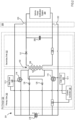
- the pre-charger 100 includes a flyback transformer 102 having a primary-side coil 104 and a secondary side coil 106.
- the secondary-side coil 106 is connected in parallel with an output capacitor 108 of the pre-charger 100 and to the load 110.
- a diode 112 controls the charging of the output capacitor 108.
- the primary-side coil 104 is connected to a first solid-state switch 114 on a first terminal of the of the primary-side coil 104 and to a second solid-state switch 116 at a second terminal of the primary-side coil 104.
- the first solid-state switch 114 and the second solid-state switch 116 are power transistors such as a metal-oxide-semiconductor field-effect transistor (MOSFET).
- MOSFET metal-oxide-semiconductor field-effect transistor
- the first solid-state switch 114 is operable to connect the positive terminal of the high voltage battery 118 and the primary-side coil 104.
- the first solid-state switch 114 is driven by a gate driver 120 operating off an isolated 12 V power supply.
- the second solid-state switch 116 is operable to connective the negative terminal of the high voltage battery 118 and the primary-side coil 104.
- the second solid-state switch is driven by a gate driver 122 operating off the isolated 12 V power supply.
- the use of solid-state switches 114, 116 compared to electromechanical switches and relays, is advantageous in that solid-state switches 114, 116 cannot weld and rarely fail to actuate.
- the primary side coil is also connected to the positive terminal of the high voltage battery 118 through a battery diode 126 and to the negative terminal of the high voltage battery 118 through a battery diode 128.
- the battery diodes 126, 128 function as inductance leakage clamping diodes.
- the current-voltage characteristics of the diodes 126, 128 is selected such that a reflected voltage in the primary-side coil that is equal to or greater than the battery charge of the high voltage battery forward-biases the battery diodes 126, 128 such that charge flows back to the high voltage battery thus preventing further increase in load.
- the pre-charger 100 includes a primary side 150 including a high voltage battery 118 that is galvanically isolated from a secondary side 152 that includes a load 110.
- the pre-charger 100 also includes a current controller 130 configured to detect current on the primary side and the secondary side.
- the current controller 130 is connected to a sense resistor 132 connected between the solid-state switch 116 and the negative terminal of the high voltage battery 118.
- the current controller is also connected to a sense resistor 134 between the secondary-side coil 106 and the load 110.
- the current sensing resistors 132, 134 may be a small resistance value to minimize the voltage drop across the pre-charger 100.
- the current controller 130 may monitor the voltage across the current sense resistors 132, 134 to control the current through the pre-charger 100. Other current sensing schemes may be possible depending on the current measurement technology selected.
- the current controller 130 provides a control signal to the gate drivers 120, 122 of solid-state switches 114, 116. Thus, the current controller 130 induces the solid-state switches 114, 116 to open and close.
- the current controller 130 may perform this current control using electronic circuitry or some combination of electronic circuitry and microprocessor based software controls.
- a desired output current range may be comprised of a lower value and an upper value. The current flowing through the pre-charge circuit may be measured. When the output current is less than the desired lower value, the switching device may be switched on. When the output current is above the desired upper value, the switching device may be switched off.
- Operation of the pre-charger 100 includes two phases.
- a first phase (or magnetizing phase)
- the solid-state switches 114, 116 are closed, allowing current to flow from the high voltage battery 118 to the primary-side coil 104.
- Current starts to flow through the primary-side coil 104, and the output diode 112 on the secondary side 152 is reverse-biased due to the transformer polarity. Therefore, all the energy is stored to the transformer 102 while the load current is supplied by the output capacitor 108.
- Current on the primary side 150 increases until reaching a threshold set in the current controller 130.
- the current controller 130 detects that the current on the primary side 150 has reached the threshold and supplies a control signal to turn off solid-state switches 114, 116, thus opening the primary side solid-state switches 114, 116.
- the solid-state switches 114, 116 are opened, the secondary side 152 starts conducting and stored energy in the transformer 102 is transferred to the output, thus supplying the load 110 and the charging output capacitor 108.
- the output diode 112 on the secondary side 152 becomes forward-biased.
- a reflected voltage is applied over the primary-side coil 104. Leakage inductance on the primary side is fed back to the high voltage battery through the battery diodes 126, 128.
- battery diodes 126, 128 prevent a further increase of load due to the reflected voltage on the primary-side coil 104 of the transformer 102 being higher than the voltage of the high voltage battery 118. Excess or unneeded charge, due to the output voltage in the capacitor 108 being equivalent to the battery voltage, is fed back to the high voltage battery.
- FIG. 2 shows a circuit diagram of an example electric vehicle power supply system 201 using an example isolated solid-state active pre-charger 100 in accordance with at least one embodiment of the present disclosure.
- a high voltage battery pack 218 of an electric vehicle is couplable to the pre-charger 100 through a main contactor circuit 206 including a positive contactor 220 and a negative contactor 222 operable by a single throw.
- the pre-charger 100 is coupled to an output capacitor 208 for a load supplied by a vehicle power distribution system 204 (e.g., connected to an electric motor).
- the high voltage battery pack 218 is also directly couplable to the output capacitor 208 and load supplied by a vehicle power distribution system 204 through the main contactor circuit 206.
- the main contactor circuit 206 is a main contactor of a battery disconnect unit (BDU) that includes one contact coupled to the positive terminal of the high voltage battery pack 218 and another contact coupled to the negative terminal of the high voltage battery pack 218.
- BDU battery disconnect unit
- the main contactor circuit 206 has a first state in which the high voltage battery pack 218 is coupled to the pre-charger 100 to pre-charge the output capacitor 208.
- the contactor has a second state in which the high voltage battery pack 218 is disconnected from the pre-charger 100 and is connected to the vehicle power distribution system 204, for example, for vehicle propulsion.
- the output capacitor 208 is first connected to the pre-charger 100 before directly connecting the high voltage battery pack 218 and output capacitor 208 to a high voltage system such as the vehicle power distribution system 204.
- the main contactor circuit 206 may be switched on and the pre-charger 100 switched off. After switching the main contactor circuit 206 on, the load voltage and the battery pack voltage may equalize, and current may flow through the main contactor circuit 206.
- the main contactor circuit 206 includes an integrated fuse.
- FIG. 3 sets forth a flow chart of an example method of operating an isolated solid-state active pre-charger in accordance with at least one embodiment of the present disclosure.
- the method of FIG. 3 includes coupling 302 a pre-charging circuit to a high voltage battery pack and a capacitive circuit, the pre-charging circuit including a flyback transformer, wherein the pre-charging circuit has a primary side and a secondary side corresponding to a primary coil and a secondary coil of the flyback transformer, wherein the high voltage battery is connected to the primary side, and wherein the capacitive circuit is coupled to the secondary side.
- the high voltage battery connected on the primary side and the capacitive circuit connected on the secondary side are galvanically isolated.
- the primary side includes one or more solid-state switches coupled between the high voltage battery and the primary-side coil of the flyback transformer.
- the one or more solid-state switches are configured to change the flyback transformer between a magnetizing phase and a demagnetizing phase.
- the one or more solid-state switches are metal-oxide-semiconductor field-effect transistors.
- the one or more solid-state switches are controlled by one or more gate drivers having an isolated power source.
- a current controller is configured to measure current in the primary side and in the secondary side and provide a control signal to the one or more gate drivers.
- the primary side also includes one or more battery diodes between the flyback transformer and the high voltage battery, where the one or more battery diodes provide inductance leakage clamping.
- the secondary side includes an output diode coupled between the flyback transformer and the capacitive circuit.
- the capacitive circuit may include one or more output capacitors.
- the method of FIG. 3 also includes activating 304 one or more solid-state switches on the primary side such that current flows from the battery pack to the primary coil.
- a first phase or magnetizing phase
- the solid-state switches are closed (switched on), allowing current to flow from the high voltage battery to the primary-side coil of the flyback transformer.
- Current starts to flow through the primary-side coil, and the output diode on the secondary side is reverse-biased due to the transformer polarity. Therefore, all the energy is stored to the flyback transformer while the load current is supplied by the capacitive circuit on the secondary side.
- Current on the primary side increases until reaching a threshold set, for example, in the current controller.
- the method of FIG. 3 also includes deactivating 306 the one or more solid-state switches such that current flows from the secondary coil to the capacitive circuit.
- the current controller detects that the current on the primary side has reached the threshold and supplies a control signal to turn off the solid-state switches, thus opening the primary side solid-state switches.
- the solid-state switches When the solid-state switches are opened, the secondary side starts conducting and stored energy in the flyback transformer is transferred to the output, thus charging output capacitor 108.
- the output diode on the secondary side becomes forward-biased.
- a reflected voltage is applied over the primary-side coil. Leakage inductance on the primary side is fed back to the high voltage battery through the battery diodes.
- the method of FIG. 3 also includes, in response to an output voltage of the pre-charging circuit being substantially equal to or greater than a charge in the high voltage battery, feeding 308 charge back to the high voltage battery. If the load voltage is substantially equal to the charge voltage in the high voltage-battery, the battery diodes prevent a further increase of load due to the reflected voltage on the primary-side coil of the transformer being higher than the voltage of the high voltage battery. Excess or unneeded charge, due to the output voltage in the capacitive circuit being equivalent to the battery voltage, is fed back to the high voltage battery through the forward-biased battery diodes.
- an isolated solid-state active pre-charger in accordance with the present disclosure provides a number of advantages, including but not limited to:
Landscapes
- Engineering & Computer Science (AREA)
- Power Engineering (AREA)
- Transportation (AREA)
- Mechanical Engineering (AREA)
- Life Sciences & Earth Sciences (AREA)
- Sustainable Development (AREA)
- Sustainable Energy (AREA)
- Charge And Discharge Circuits For Batteries Or The Like (AREA)
- Dc-Dc Converters (AREA)
Abstract
In an embodiment, a power supply system having an isolated solid-state active precharger includes a high voltage battery; a capacitive circuit; and a pre-charging circuit configured to charge the capacitive circuit from the high voltage battery, the pre-charging circuit including a flyback transformer and having a primary side and a secondary side corresponding to a primary coil and a secondary coil of the flyback transformer, wherein the high voltage battery is connected to the primary side, wherein the capacitive circuit is coupled to the secondary side, and wherein charge is fed back to the high voltage battery when an output voltage of the secondary side is substantially equal to or greater than a charge in the high voltage battery.
Description
- Electromechanical switching devices, such as contactors and relays, are designed to carry a certain amount of electrical current for certain periods of time. Such devices are particularly important in electric vehicles. Typically, electric vehicles include one or more high voltage batteries connected, via a main contactor, to a vehicle power distribution system for powering an electric motor. The main contactor is typically an electromechanical switch that opens or closes high current paths between the battery packs and the vehicle power distribution system. To facilitate switching in a high voltage system, a pre-charge circuit is used to charge an output capacitor to the battery voltage before connecting the high voltage system to the high voltage battery pack.
- Embodiments in accordance with the present disclosure are directed to apparatuses, systems, and methods for an isolated solid-state active pre-charger. The circuitry of the pre-charger uses a two-switch flyback converter topology in which a high voltage battery pack is galvanically isolated from a load. A capacitive circuit is pre-charged by the pre-charger circuitry before connecting the load to the high voltage battery pack. Solid-state switches are used to eliminate moving parts found in relays and other electromechanical switches, thus increasing reliability. Excess or unneeded charge is fed back to the battery when the output voltage is equivalent to the battery pack charge voltage. Diodes used for leakage inductance clamping may also be utilized to feed the excess charge back to the battery.
- A particular embodiment is directed to a power supply system having an isolated solid-state active precharger, the power supply system including a high voltage battery; a capacitive circuit; and a pre-charging circuit configured to charge the capacitive circuit from the high voltage battery, the pre-charging circuit including a flyback transformer and having a primary side and a secondary side corresponding to a primary coil and a secondary coil of the flyback transformer, where the high voltage battery is connected to the primary side, where the capacitive circuit is coupled to the secondary side, and where charge is fed back to the high voltage battery when an output voltage of the secondary side is substantially equal to or greater than a charge in the high voltage battery. In some examples, the high voltage battery connected on the primary side and the capacitive circuit connected on the secondary side are galvanically isolated. In some examples, the output voltage is measured by a reflected voltage in the primary side during a demagnetizing phase.
- In some examples, the primary side includes one or more battery diodes coupled to the flyback transformer and the high voltage battery, where the one or more battery diodes provide inductance leakage clamping and feeds charge to the high voltage battery when the output voltage of the secondary side is substantially equal to or greater than the charge in the high voltage battery.
- In some examples, the primary side includes one or more solid-state switches coupled between the high voltage battery and the flyback transformer, where the one or more solid-state switches are configured to change the flyback transformer between a magnetizing phase and a demagnetizing phase. In some variations, the one or more solid-state switches are metal-oxide-semiconductor field-effect transistors. In some examples, the one or more solid-state switches are controlled by one or more gate drivers having an isolated power source. In some variations, a current controller is configured to: measure current in the primary side and in the secondary side; and provide a control signal to the one or more gate drivers.
- In some examples, the secondary side includes an output diode coupled between the flyback transformer and the capacitive circuit.
- In some examples, the power supply system further includes a main contactor circuit coupled to the high voltage battery and the capacitive circuit in parallel with the pre-charge circuit, the main contactor circuit including a positive-terminal contactor and a negative terminal contactor; and a load coupled to the main contactor circuit in parallel with the capacitive circuit. In some variations, the load is provided by a vehicle power distribution system. In some examples, the capacitive circuit is charged by the pre-charge circuit prior to connecting the load to the high voltage battery through the main contactor circuit.
- Another embodiment is directed to an electric vehicle having a power supply system including an isolated solid-state active precharger, the electric vehicle including a high voltage battery; a capacitive circuit; a pre-charging circuit configured to charge the capacitive circuit from the high voltage battery, the pre-charging circuit including a flyback transformer and having a primary side and a secondary side corresponding to a primary coil and a secondary coil of the flyback transformer, where the high voltage battery is connected to the primary side, where the capacitive circuit is coupled to the secondary side, and where charge is fed back to the high voltage battery when an output voltage of the secondary side is substantially equal to or greater than a charge in the high voltage battery; a main contactor circuit coupled to the high voltage battery and the capacitive circuit in parallel with the pre-charge circuit, the main contactor circuit including a positive-terminal contactor and a negative terminal contactor; and a vehicle power distribution system connected across the main contactor circuit and the capacitive circuit.
- Another embodiment is directed to a method of operating a power supply system including an isolated solid-state active precharger, the method including coupling a pre-charging circuit to a high voltage battery and a capacitive circuit, the pre-charging circuit including a flyback transformer, where the pre-charging circuit has a primary side and a secondary side corresponding to a primary coil and a secondary coil of the flyback transformer, where the high voltage battery is connected to the primary side, and where the capacitive circuit is coupled to the secondary side. The method also includes activating one or more solid-state switches on the primary side such that current flows from the high voltage battery to the primary coil. The method also includes deactivating the one or more solid-state switches such that current flows from the secondary coil to the capacitive circuit. The method also includes, in response to an output voltage of the pre-charging circuit being substantially equal to or greater than a charge in the high voltage battery, feeding charge back to the high voltage battery.
- These and other features, aspects, and advantages of the present disclosure will become better understood when the following detailed description is read with reference to the accompanying drawings in which like characters represent like parts throughout the drawings.
-
-
FIG. 1 is an example circuit schematic for an example isolated solid-state active pre-charger in accordance with at least one embodiment of the present disclosure. -
FIG. 2 is an example circuit schematic for another example isolated solid-state active pre-charger in accordance with at least one embodiment of the present disclosure. -
FIG. 3 is a flowchart of an example method for operating a power system supply that includes an isolated solid-state active pre-charger in accordance with at least one embodiment of the present disclosure. - The terminology used herein for the purpose of describing particular examples is not intended to be limiting for further examples. Whenever a singular form such as "a", "an" and "the" is used and using only a single element is neither explicitly or implicitly defined as being mandatory, further examples may also use plural elements to implement the same functionality. Likewise, when a functionality is subsequently described as being implemented using multiple elements, further examples may implement the same functionality using a single element or processing entity. It will be further understood that the terms "comprises", "comprising", "includes" and/or "including", when used, specify the presence of the stated features, integers, steps, operations, processes, acts, elements and/or components, but do not preclude the presence or addition of one or more other features, integers, steps, operations, processes, acts, elements, components and/or any group thereof.
- It will be understood that when an element is referred to as being "connected" or "coupled" to another element, the elements may be directly connected or coupled via one or more intervening elements. If two elements A and B are combined using an "or", this is to be understood to disclose all possible combinations, i.e. only A, only B, as well as A and B. An alternative wording for the same combinations is "at least one of A and B". The same applies for combinations of more than two elements.
- Accordingly, while further examples are capable of various modifications and alternative forms, some particular examples thereof are shown in the figures and will subsequently be described in detail. However, this detailed description does not limit further examples to the particular forms described. Further examples may cover all modifications, equivalents, and alternatives falling within the scope of the disclosure. Like numbers refer to like or similar elements throughout the description of the figures, which may be implemented identically or in modified form when compared to one another while providing for the same or a similar functionality.
- Many pre-charge systems for electric vehicle battery connect units are resistive-based. The pre-charge circuit includes a relay and a resistor (typically in the 20-40 Ohm range). A 12 Volt (V) signal closes the relay and bridges the main contactor. However, high thermal dissipation in larger vehicles leads to physically large solutions. Further, the resistive pre-charger never charges the capacitance to 100% of the battery voltage. This requires that the main contactor always has to close into a voltage differential, leading to wear. As pre-charge commences, a current surge is initiated and limited solely by the resistive value and the battery voltage. As the capacitance is charged, current quickly drops. A voltage difference across a main contactor allows sudden flow of current, limited only by the low resistance of the high voltage battery and the vehicle electrical distribution system, when the contactor is closed. This may reduce the life of the contactor. When a resistor is used in the pre-charge circuit, the voltage across the main contactor can never be zero because of the resistance. In addition, measurement errors are introduced as two sensor values must be measured and processed. Depending on the resolution of the voltage measurement, it may not be feasible to determine a difference that is close to zero. These measurement errors may stack up under certain conditions and allow the main contactor to be closed with a voltage difference greater than zero leading to a lower contactor life.
- Embodiments in accordance with the present disclosure provide a solid-state (e.g., no moving parts), galvanically isolated method of pre-charging capacitors in electronic systems such as electric motor inverters. In some examples, a pre-charge system includes a self-oscillating, current controlled two-switch flyback transformer powered by a 12V control signal. An output voltage is effectively "compared" to the battery voltage through the reflected voltage during the demagnetization phase of the transformer cycle. If the output voltage is approximately equal to the battery voltage, excess or unneeded charge voltage is recycled back into the battery. Diodes used for leakage inductance clamping may also be utilized to recycle charge back to the battery, thus reducing or eliminating the need for additional components. Solid-state pre-charge that is not based on resistive current limiting has significant efficiency benefits. Resistive based pre-charging has an approximately 50% efficiency. Solid-state pre-charge increases this to in excess of 85% (with potential above 95%). This significantly reduces thermal dissipation and therefore does not require any thermal management.
- Exemplary methods and apparatuses for a battery configuration contactor in accordance with the present disclosure are described with reference to the accompanying drawings, beginning with
FIG. 1. FIG. 1 shows a circuit diagram of an example isolated solid-state activepre-charger system 101 in accordance with at least one embodiment of the present disclosure. The pre-charger system includes a pre-charger 100 coupled to a high voltage battery 118 (e.g., a 400 V or more battery) for pre-charging a capacitive circuit including one ormore output capacitors 108 coupled to aload 110 across a direct current bus. The pre-charger 100 implements a two-solid-state switch flyback converter in which excess charge is recycled to the battery when the output voltage is substantially the same as or greater than the battery voltage. The pre-charger 100 includes aflyback transformer 102 having a primary-side coil 104 and asecondary side coil 106. The secondary-side coil 106 is connected in parallel with anoutput capacitor 108 of the pre-charger 100 and to theload 110. Adiode 112 controls the charging of theoutput capacitor 108. The primary-side coil 104 is connected to a first solid-state switch 114 on a first terminal of the of the primary-side coil 104 and to a second solid-state switch 116 at a second terminal of the primary-side coil 104. - In some examples, the first solid-
state switch 114 and the second solid-state switch 116 are power transistors such as a metal-oxide-semiconductor field-effect transistor (MOSFET). The first solid-state switch 114 is operable to connect the positive terminal of thehigh voltage battery 118 and the primary-side coil 104. The first solid-state switch 114 is driven by agate driver 120 operating off an isolated 12 V power supply. The second solid-state switch 116 is operable to connective the negative terminal of thehigh voltage battery 118 and the primary-side coil 104. The second solid-state switch is driven by agate driver 122 operating off the isolated 12 V power supply. The use of solid-state switches state switches - The primary side coil is also connected to the positive terminal of the
high voltage battery 118 through abattery diode 126 and to the negative terminal of thehigh voltage battery 118 through abattery diode 128. In some examples, thebattery diodes diodes battery diodes - In view of the above arrangement, it is apparent that the pre-charger 100 includes a
primary side 150 including ahigh voltage battery 118 that is galvanically isolated from asecondary side 152 that includes aload 110. The pre-charger 100 also includes acurrent controller 130 configured to detect current on the primary side and the secondary side. In one example, thecurrent controller 130 is connected to asense resistor 132 connected between the solid-state switch 116 and the negative terminal of thehigh voltage battery 118. In this example, the current controller is also connected to asense resistor 134 between the secondary-side coil 106 and theload 110. Thecurrent sensing resistors current controller 130 may monitor the voltage across thecurrent sense resistors - The
current controller 130 provides a control signal to thegate drivers state switches current controller 130 induces the solid-state switches current controller 130 may perform this current control using electronic circuitry or some combination of electronic circuitry and microprocessor based software controls. A desired output current range may be comprised of a lower value and an upper value. The current flowing through the pre-charge circuit may be measured. When the output current is less than the desired lower value, the switching device may be switched on. When the output current is above the desired upper value, the switching device may be switched off. - Operation of the pre-charger 100 includes two phases. In a first phase (or magnetizing phase), the solid-
state switches high voltage battery 118 to the primary-side coil 104. Current starts to flow through the primary-side coil 104, and theoutput diode 112 on thesecondary side 152 is reverse-biased due to the transformer polarity. Therefore, all the energy is stored to thetransformer 102 while the load current is supplied by theoutput capacitor 108. Current on theprimary side 150 increases until reaching a threshold set in thecurrent controller 130. In a second phase (or demagnetizing phase), thecurrent controller 130 detects that the current on theprimary side 150 has reached the threshold and supplies a control signal to turn off solid-state switches state switches state switches secondary side 152 starts conducting and stored energy in thetransformer 102 is transferred to the output, thus supplying theload 110 and the chargingoutput capacitor 108. Theoutput diode 112 on thesecondary side 152 becomes forward-biased. At the same time, a reflected voltage is applied over the primary-side coil 104. Leakage inductance on the primary side is fed back to the high voltage battery through thebattery diodes battery diodes side coil 104 of thetransformer 102 being higher than the voltage of thehigh voltage battery 118. Excess or unneeded charge, due to the output voltage in thecapacitor 108 being equivalent to the battery voltage, is fed back to the high voltage battery. - For further explanation,
FIG. 2 shows a circuit diagram of an example electric vehiclepower supply system 201 using an example isolated solid-state active pre-charger 100 in accordance with at least one embodiment of the present disclosure. In theexample system 201, a highvoltage battery pack 218 of an electric vehicle is couplable to the pre-charger 100 through amain contactor circuit 206 including apositive contactor 220 and anegative contactor 222 operable by a single throw. The pre-charger 100 is coupled to anoutput capacitor 208 for a load supplied by a vehicle power distribution system 204 (e.g., connected to an electric motor). The highvoltage battery pack 218 is also directly couplable to theoutput capacitor 208 and load supplied by a vehicle power distribution system 204 through themain contactor circuit 206. In some examples, themain contactor circuit 206 is a main contactor of a battery disconnect unit (BDU) that includes one contact coupled to the positive terminal of the highvoltage battery pack 218 and another contact coupled to the negative terminal of the highvoltage battery pack 218. In some examples, themain contactor circuit 206 has a first state in which the highvoltage battery pack 218 is coupled to the pre-charger 100 to pre-charge theoutput capacitor 208. The contactor has a second state in which the highvoltage battery pack 218 is disconnected from the pre-charger 100 and is connected to the vehicle power distribution system 204, for example, for vehicle propulsion. Thus, to pre-charge theoutput capacitor 208, theoutput capacitor 208 is first connected to the pre-charger 100 before directly connecting the highvoltage battery pack 218 andoutput capacitor 208 to a high voltage system such as the vehicle power distribution system 204. When the pre-charge operation is completed, themain contactor circuit 206 may be switched on and the pre-charger 100 switched off. After switching themain contactor circuit 206 on, the load voltage and the battery pack voltage may equalize, and current may flow through themain contactor circuit 206. In some examples themain contactor circuit 206 includes an integrated fuse. - For further explanation,
FIG. 3 sets forth a flow chart of an example method of operating an isolated solid-state active pre-charger in accordance with at least one embodiment of the present disclosure. The method ofFIG. 3 includes coupling 302 a pre-charging circuit to a high voltage battery pack and a capacitive circuit, the pre-charging circuit including a flyback transformer, wherein the pre-charging circuit has a primary side and a secondary side corresponding to a primary coil and a secondary coil of the flyback transformer, wherein the high voltage battery is connected to the primary side, and wherein the capacitive circuit is coupled to the secondary side. In some examples, the high voltage battery connected on the primary side and the capacitive circuit connected on the secondary side are galvanically isolated. In some examples, the primary side includes one or more solid-state switches coupled between the high voltage battery and the primary-side coil of the flyback transformer. The one or more solid-state switches are configured to change the flyback transformer between a magnetizing phase and a demagnetizing phase. In some variations, the one or more solid-state switches are metal-oxide-semiconductor field-effect transistors. In some examples, the one or more solid-state switches are controlled by one or more gate drivers having an isolated power source. In some variations, a current controller is configured to measure current in the primary side and in the secondary side and provide a control signal to the one or more gate drivers. In some examples, the primary side also includes one or more battery diodes between the flyback transformer and the high voltage battery, where the one or more battery diodes provide inductance leakage clamping. In some examples, the secondary side includes an output diode coupled between the flyback transformer and the capacitive circuit. The capacitive circuit may include one or more output capacitors. - The method of
FIG. 3 also includes activating 304 one or more solid-state switches on the primary side such that current flows from the battery pack to the primary coil. In a first phase (or magnetizing phase), the solid-state switches are closed (switched on), allowing current to flow from the high voltage battery to the primary-side coil of the flyback transformer. Current starts to flow through the primary-side coil, and the output diode on the secondary side is reverse-biased due to the transformer polarity. Therefore, all the energy is stored to the flyback transformer while the load current is supplied by the capacitive circuit on the secondary side. Current on the primary side increases until reaching a threshold set, for example, in the current controller. - The method of
FIG. 3 also includes deactivating 306 the one or more solid-state switches such that current flows from the secondary coil to the capacitive circuit. In a second phase (or demagnetizing phase), the current controller, for example, detects that the current on the primary side has reached the threshold and supplies a control signal to turn off the solid-state switches, thus opening the primary side solid-state switches. When the solid-state switches are opened, the secondary side starts conducting and stored energy in the flyback transformer is transferred to the output, thus chargingoutput capacitor 108. The output diode on the secondary side becomes forward-biased. At the same time, a reflected voltage is applied over the primary-side coil. Leakage inductance on the primary side is fed back to the high voltage battery through the battery diodes. - The method of
FIG. 3 also includes, in response to an output voltage of the pre-charging circuit being substantially equal to or greater than a charge in the high voltage battery, feeding 308 charge back to the high voltage battery. If the load voltage is substantially equal to the charge voltage in the high voltage-battery, the battery diodes prevent a further increase of load due to the reflected voltage on the primary-side coil of the transformer being higher than the voltage of the high voltage battery. Excess or unneeded charge, due to the output voltage in the capacitive circuit being equivalent to the battery voltage, is fed back to the high voltage battery through the forward-biased battery diodes. - In view of the foregoing, it will be appreciated that an isolated solid-state active pre-charger in accordance with the present disclosure provides a number of advantages, including but not limited to:
- an absence of moving parts, such as relays, that can weld closed or fail to actuate;
- galvanic isolation between battery and all loads;
- a reduction of thermal management requirements;
- faster pre-charging through closed loop current control;
- accurate 100% completion of pre-charge (e.g., compared to less than 100% for resistive based solutions);
- isolated output enables easier use of an integrated dual contactor between the battery and load (positive and negative switched with a single dual pole contactor).
- It will be understood from the foregoing description that modifications and changes may be made in various embodiments of the present disclosure without departing from its true spirit. The descriptions in this specification are for purposes of illustration only and are not to be construed in a limiting sense. The scope of the present disclosure is limited only by the language of the following claims.
Claims (20)
- A power supply system having an isolated solid-state active precharger, the power supply system comprising:a high voltage battery;a capacitive circuit; anda pre-charging circuit configured to charge the capacitive circuit from the high voltage battery, the pre-charging circuit including a flyback transformer and having a primary side and a secondary side corresponding to a primary coil and a secondary coil of the flyback transformer, wherein the high voltage battery is connected to the primary side, wherein the capacitive circuit is coupled to the secondary side, and wherein charge is fed back to the high voltage battery when an output voltage of the secondary side is substantially equal to or greater than a charge in the high voltage battery.
- The power supply system of claim 1, wherein the high voltage battery connected on the primary side and the capacitive circuit connected on the secondary side are galvanically isolated.
- The power supply system of claim 1, wherein the output voltage is measured by a reflected voltage in the primary side during a demagnetizing phase.
- The power supply system of claim 1, wherein the primary side includes one or more battery diodes coupled to the flyback transformer and the high voltage battery, wherein the one or more battery diodes provide inductance leakage clamping and feeds charge to the high voltage battery when the output voltage of the secondary side is substantially equal to or greater than the charge in the high voltage battery.
- The power supply system of claim 1, wherein the primary side includes one or more solid-state switches coupled between the high voltage battery and the flyback transformer, wherein the one or more solid-state switches are configured to change the flyback transformer between a magnetizing phase and a demagnetizing phase.
- The power supply system of claim 5, wherein the one or more solid-state switches are metal-oxide-semiconductor field-effect transistors.
- The power supply system of claim 5, wherein the one or more solid-state switches are controlled by one or more gate drivers having an isolated power source.
- The power supply system of claim 7, wherein a current controller is configured to:
measure current in the primary side and in the secondary side; and provide a control signal to the one or more gate drivers. - The power supply system of claim 1, wherein the secondary side includes an output diode coupled between the flyback transformer and the capacitive circuit.
- The power supply system of claim 1 further comprising:a main contactor circuit coupled to the high voltage battery and the capacitive circuit in parallel with the pre-charge circuit, the main contactor circuit including a positive-terminal contactor and a negative terminal contactor; anda load coupled to the main contactor circuit in parallel with the capacitive circuit.
- The power supply system of claim 10, wherein the load is provided by a vehicle power distribution system.
- The power supply system of claim 10, wherein the capacitive circuit is charged by the pre-charge circuit prior to connecting the load to the high voltage battery through the main contactor circuit.
- An electric vehicle having a power supply system including an isolated solid-state active precharger, the electric vehicle comprising:a high voltage battery;a capacitive circuit;a pre-charging circuit configured to charge the capacitive circuit from the high voltage battery, the pre-charging circuit including a flyback transformer and having a primary side and a secondary side corresponding to a primary coil and a secondary coil of the flyback transformer, wherein the high voltage battery is connected to the primary side, wherein the capacitive circuit is coupled to the secondary side, and wherein charge is fed back to the high voltage battery when an output voltage of the secondary side is substantially equal to or greater than a charge in the high voltage battery;a main contactor circuit coupled to the high voltage battery and the capacitive circuit in parallel with the pre-charge circuit, the main contactor circuit including a positive-terminal contactor and a negative terminal contactor; anda vehicle power distribution system connected across the main contactor circuit and the capacitive circuit.
- A method of operating a power supply system including an isolated solid-state active precharger, the method comprising:coupling a pre-charging circuit to a high voltage battery and a capacitive circuit, the pre-charging circuit including a flyback transformer, wherein the pre-charging circuit has a primary side and a secondary side corresponding to a primary coil and a secondary coil of the flyback transformer, wherein the high voltage battery is connected to the primary side, and wherein the capacitive circuit is coupled to the secondary side;activating one or more solid-state switches on the primary side such that current flows from the high voltage battery to the primary coil;deactivating the one or more solid-state switches such that current flows from the secondary coil to the capacitive circuit; andin response to an output voltage of the pre-charging circuit being substantially equal to or greater than a charge in the high voltage battery, feeding charge back to the high voltage battery.
- The method of claim 14, wherein the high voltage battery connected on the primary side and the capacitive circuit connected on the secondary side are galvanically isolated.
- The method of claim 14, wherein the output voltage is measured by a reflected voltage in the primary side during a demagnetizing phase.
- The method of claim 14, wherein the primary side includes one or more battery diodes coupled to the flyback transformer and the high voltage battery, wherein the one or more battery diodes provide inductance leakage clamping and feeds charge to the high voltage battery when the output voltage of the secondary side is substantially equal to or greater than the charge in the high voltage battery.
- The method of claim 14, wherein the one or more solid-state switches are coupled between the high voltage battery and the flyback transformer, wherein the one or more solid-state switches are configured to change the flyback transformer between a magnetizing phase and a demagnetizing phase.
- The method of claim 18, wherein the one or more solid-state switches are controlled by one or more gate drivers having an isolated power source.
- The method of claim 19, wherein a current controller is configured to: measure current in the primary side and in the secondary side; and provide a control signal to the one or more gate drivers.
Applications Claiming Priority (1)
| Application Number | Priority Date | Filing Date | Title |
|---|---|---|---|
| US18/187,269 US20240322696A1 (en) | 2023-03-21 | 2023-03-21 | Isolated solid-state active pre-charger |
Publications (1)
| Publication Number | Publication Date |
|---|---|
| EP4447262A1 true EP4447262A1 (en) | 2024-10-16 |
Family
ID=90368494
Family Applications (1)
| Application Number | Title | Priority Date | Filing Date |
|---|---|---|---|
| EP24164655.3A Pending EP4447262A1 (en) | 2023-03-21 | 2024-03-19 | Isolated solid-state active pre-charger |
Country Status (4)
| Country | Link |
|---|---|
| US (1) | US20240322696A1 (en) |
| EP (1) | EP4447262A1 (en) |
| KR (1) | KR20250090143A (en) |
| CN (1) | CN118693970A (en) |
Citations (2)
| Publication number | Priority date | Publication date | Assignee | Title |
|---|---|---|---|---|
| WO2014120153A1 (en) * | 2013-01-30 | 2014-08-07 | Schneider Electric It Corporation | Flyback converter |
| US20190036442A1 (en) * | 2017-07-28 | 2019-01-31 | Apple Inc. | Primary side control of primary resonant flyback converters |
Family Cites Families (124)
| Publication number | Priority date | Publication date | Assignee | Title |
|---|---|---|---|---|
| US3938020A (en) * | 1975-02-11 | 1976-02-10 | Gould, Inc. | Charger circuit for accessory battery |
| US4374355A (en) * | 1981-03-02 | 1983-02-15 | General Electric Company | Electrically isolated battery charger for on-board electric vehicle applications |
| US4536696A (en) * | 1983-07-14 | 1985-08-20 | At&T Bell Laboratories | Buck-boost converter with dual-mode control for battery charging |
| WO1988002565A1 (en) * | 1986-09-29 | 1988-04-07 | Black & Decker Inc. | Non-isolated thermally responsive battery charger |
| US5329220A (en) * | 1987-10-27 | 1994-07-12 | Hase A M | Shunt control |
| US5043650A (en) * | 1988-02-26 | 1991-08-27 | Black & Decker Inc. | Battery charger |
| US5266881A (en) * | 1989-04-11 | 1993-11-30 | Solid State Chargers Research And Development Limited | Universal high current battery charger |
| US5113127A (en) * | 1989-04-11 | 1992-05-12 | Solid State Chargers, Inc. | Universal battery charger |
| US5270635A (en) * | 1989-04-11 | 1993-12-14 | Solid State Chargers, Inc. | Universal battery charger |
| IE75374B1 (en) * | 1989-11-13 | 1997-09-10 | Nat Csf Corp | Uninterruptible power supply |
| US5304917A (en) * | 1990-11-30 | 1994-04-19 | Burr-Brown Corporation | Compact low noise low power dual mode battery charging circuit |
| US5254932A (en) * | 1990-12-24 | 1993-10-19 | Magnetek, Inc. | Charging voltage control circuit for battery chargers |
| US5192905A (en) * | 1990-12-24 | 1993-03-09 | Magnetek, Inc. | Charging voltage control and current limit for battery chargers |
| US5302858A (en) * | 1991-12-11 | 1994-04-12 | Best Power Technology, Incorporated | Method and apparatus for providing battery charging in a backup power system |
| US5285779A (en) * | 1992-03-27 | 1994-02-15 | Hewlett-Packard Company | Method and apparatus for a cardiac defibrillator high voltage charging circuit |
| GB9500969D0 (en) * | 1995-01-18 | 1995-03-08 | Magnum Power Solutions Ltd | Uninterruptible power supplies |
| US5631814A (en) * | 1995-06-16 | 1997-05-20 | Abraham Lavsky | Uninterruptible power supply based on non-invasive connection of backup circuit to switch power supply |
| US5694025A (en) * | 1996-04-23 | 1997-12-02 | Motorola, Inc. | Battery charger with control circuit |
| US5896280A (en) * | 1997-11-25 | 1999-04-20 | Exide Electronics Corporation | Frequency converter and improved UPS employing the same |
| US5798671A (en) * | 1997-04-04 | 1998-08-25 | Renaissance Systems, Inc. | Charge coupled, silicon controlled power supply/battery charger |
| CA2311529A1 (en) * | 1997-11-25 | 1999-06-03 | Powerware Corporation | Charge circuits for ups |
| US9397370B2 (en) * | 1999-06-25 | 2016-07-19 | The Board Of Trustees Of The University Of Illinois | Single and multiple cell battery with built-in controller |
| JP3280642B2 (en) * | 1999-09-08 | 2002-05-13 | 長野日本無線株式会社 | Power storage module |
| US6359794B1 (en) * | 1999-12-01 | 2002-03-19 | Acme Electric Corporation | Battery backup power supply |
| US6456511B1 (en) * | 2000-02-17 | 2002-09-24 | Tyco Electronics Corporation | Start-up circuit for flyback converter having secondary pulse width modulation |
| WO2001078091A1 (en) * | 2000-04-06 | 2001-10-18 | Aria Corporation | Miniaturized ac/dc power supply and battery charger |
| US6396244B2 (en) * | 2000-04-07 | 2002-05-28 | Toyota Jidosha Kabushiki Kaisha | Electric element control apparatus, battery system, and inverter motor system |
| US6362979B1 (en) * | 2000-09-29 | 2002-03-26 | Jeff Gucyski | Switching power amplifier and uninterruptible power system comprising DC/DC converter for providing sinusoidal output |
| US6339314B1 (en) * | 2000-12-27 | 2002-01-15 | Philips Electronics North America Corporation | Battery charger circuit with low standby power dissipation |
| US6479970B2 (en) * | 2001-04-03 | 2002-11-12 | Anantha B. Reddy | Un-interruptible power supply |
| US6734651B2 (en) * | 2001-06-06 | 2004-05-11 | Simtech Systems, Llc | Battery backup system with remote switch for actuating backup battery |
| US6664762B2 (en) * | 2001-08-21 | 2003-12-16 | Power Designers, Llc | High voltage battery charger |
| EP1451921A4 (en) * | 2001-11-02 | 2006-01-11 | Aker Wade Power Technologies L | QUICK CHARGER FOR HIGH CAPACITY BATTERIES |
| US6683393B2 (en) * | 2001-12-31 | 2004-01-27 | James M. Lewis | MOSFET based, high voltage, electronic relays for AC power switching and inductive loads |
| US7439636B2 (en) * | 2001-12-31 | 2008-10-21 | Lewis James M | Driver system for MOSFET based, high voltage electronic relays for AC power switching and inductive loads |
| US7230354B2 (en) * | 2001-12-31 | 2007-06-12 | Lewis James M | Driver system for MOSFET based, high voltage, electronic relays for AC power switching and inductive loads |
| US7183672B2 (en) * | 2001-12-31 | 2007-02-27 | Lewis James M | MOSFET based, high voltage, electronic relays for AC power switching and inductive loads |
| US6788039B2 (en) * | 2002-11-14 | 2004-09-07 | International Rectifier Corporation | Low power inductorless DC-DC Regulator with capacitive charging/discharging |
| US6909617B1 (en) * | 2004-01-22 | 2005-06-21 | La Marche Manufacturing Co. | Zero-voltage-switched, full-bridge, phase-shifted DC-DC converter with improved light/no-load operation |
| US7576451B2 (en) * | 2005-09-28 | 2009-08-18 | Rockwell Automation Technologies, Inc. | Self powered gate driver system |
| US20070223907A1 (en) * | 2006-03-24 | 2007-09-27 | Kwang-Hwa Liu | Photo-flash driving circuit |
| US9083254B1 (en) * | 2006-11-20 | 2015-07-14 | Picor Corporation | Primary side sampled feedback control in power converters |
| HUP0700299A2 (en) * | 2007-04-24 | 2008-12-29 | Andras Fazakas | Recharger circuit for recharging two batteries |
| US7920396B2 (en) * | 2007-07-13 | 2011-04-05 | National Semiconductor Corporation | Synchronous rectifier and controller for inductive coupling |
| US7969128B2 (en) * | 2007-11-20 | 2011-06-28 | Lockheed Martin Corporation | Bi-directional power supply with isolated output |
| US20090179496A1 (en) * | 2008-01-15 | 2009-07-16 | Cyber Power System Inc. | Power saving uninterruptible power supply |
| US8536824B2 (en) * | 2008-04-18 | 2013-09-17 | Mi-Jack Canada, Inc. | Lossless dynamic battery equalizer system and method |
| JP2010166637A (en) * | 2009-01-13 | 2010-07-29 | Panasonic Corp | Charging control circuit |
| DE102009000328A1 (en) * | 2009-01-20 | 2010-07-22 | Semikron Elektronik Gmbh & Co. Kg | Battery charger and method of operation |
| US8541980B2 (en) * | 2009-05-22 | 2013-09-24 | Intersil Americas LLC | System and method for cell balancing and charging |
| US8283896B1 (en) * | 2009-06-03 | 2012-10-09 | Polarity, Inc. | Method and system for charging and discharging high-voltage energy storage devices |
| AU2010202975A1 (en) * | 2009-07-16 | 2011-02-03 | Demain International Pty Ltd | Power supply for charging high energy capacitor |
| JP5266171B2 (en) * | 2009-09-15 | 2013-08-21 | 本田技研工業株式会社 | Electric vehicle |
| DE102009055331A1 (en) * | 2009-12-28 | 2011-06-30 | Robert Bosch GmbH, 70469 | Device and method for detecting a reverse polarity on a low-voltage side of a DC-DC converter in a two-voltage on-board network |
| CN102111008A (en) * | 2009-12-29 | 2011-06-29 | 台达电子工业股份有限公司 | High-voltage battery charging system architecture of electric automobile |
| US8129951B2 (en) * | 2010-07-16 | 2012-03-06 | Delphi Technologies, Inc. | Power charging assembly and method that includes a low voltage electrical device operable with pulse width modulation (PWM) control |
| JP5577986B2 (en) * | 2010-09-22 | 2014-08-27 | 株式会社豊田自動織機 | Power supply device and in-vehicle power supply device |
| FR2972581B1 (en) * | 2011-03-09 | 2015-01-02 | Commissariat Energie Atomique | CHARGE BALANCING SYSTEM FOR BATTERIES |
| KR101577517B1 (en) * | 2011-05-25 | 2015-12-14 | 가부시키가이샤 히타치세이사쿠쇼 | Charging system |
| US9024476B2 (en) * | 2011-07-28 | 2015-05-05 | Schneider Electric It Corporation | Single-battery power topologies for online UPS systems |
| US8957542B2 (en) * | 2011-07-29 | 2015-02-17 | Schneider Electric It Corporation | Non-isolated AC-DC converter having a positive output buck-boost converter and PFC at input supply |
| JP5387628B2 (en) * | 2011-07-29 | 2014-01-15 | Tdk株式会社 | Current type isolated converter |
| US8884464B2 (en) * | 2011-08-29 | 2014-11-11 | Schneider Electric It Corporation | Twin boost converter with integrated charger for UPS system |
| JP2013123306A (en) * | 2011-12-09 | 2013-06-20 | Toyota Industries Corp | Non-contact power transmission device |
| US9365115B2 (en) * | 2012-01-20 | 2016-06-14 | Ford Global Technologies, Llc | System and method for vehicle power management |
| US9209676B2 (en) * | 2012-12-07 | 2015-12-08 | Motorola Solutions, Inc. | Method and apparatus for charging batteries having different voltage ranges with a single conversion charger |
| EP3039778A4 (en) * | 2013-09-01 | 2017-04-26 | QuantumScape Corporation | Dc-dc converter for battery system with wide operating voltage range |
| EP3104508B1 (en) * | 2014-02-05 | 2018-09-26 | Mitsubishi Electric Corporation | In-vehicle charger and surge-suppression method for in-vehicle charger |
| US9887564B2 (en) * | 2014-02-13 | 2018-02-06 | Infineon Technologies Austria Ag | Switched mode power supply circuit |
| FR3017754B1 (en) * | 2014-02-14 | 2018-04-27 | Commissariat A L'energie Atomique Et Aux Energies Alternatives | CONTINUOUS VOLTAGE SUPPLY SYSTEM CONFIGURED TO PRECHARGE A FILTER CAPACITOR BEFORE FEEDING A LOAD |
| US9948187B2 (en) * | 2014-04-01 | 2018-04-17 | Infineon Technologies Austria Ag | System and method for a switched-mode power supply |
| US9479067B2 (en) * | 2014-04-01 | 2016-10-25 | Infineon Technologies Austria Ag | System and method for a switched-mode power supply |
| JP6202203B2 (en) * | 2014-05-28 | 2017-09-27 | 富士電機株式会社 | Charger |
| JP6284496B2 (en) * | 2015-02-20 | 2018-02-28 | オムロンオートモーティブエレクトロニクス株式会社 | Voltage converter |
| KR101734641B1 (en) * | 2015-04-14 | 2017-05-11 | 현대자동차주식회사 | Charging device of vehicle |
| EP3298673A4 (en) * | 2015-05-21 | 2019-05-22 | Robert Bosch GmbH | INTEGRATING A BATTERY MANAGEMENT SYSTEM AND BATTERY CHARGER |
| DE102015109692A1 (en) * | 2015-06-17 | 2016-12-22 | Infineon Technologies Austria Ag | Switching converter with signal transmission from secondary side to primary side |
| US9761913B2 (en) * | 2015-08-26 | 2017-09-12 | Solarcity Corporation | High efficiency high voltage battery pack for onsite power generation systems |
| EP3347963A4 (en) * | 2015-09-11 | 2019-01-16 | Invertedpower Pty Ltd | CONTROLLER FOR INDUCTIVE LOAD HAVING ONE OR MORE INDUCTIVE WINDINGS |
| US10879805B2 (en) * | 2015-09-22 | 2020-12-29 | Infineon Technologies Austria Ag | System and method for a switched-mode power supply having a transformer with a plurality of primary windings |
| US10150358B2 (en) * | 2015-12-17 | 2018-12-11 | Erik Orlando Soto | Generator and electrical motor for multi-axle vehicles |
| US20170282747A1 (en) * | 2016-04-05 | 2017-10-05 | Ford Global Technologies, Llc | Charging system for vehicle battery |
| DE102016220279A1 (en) * | 2016-10-17 | 2018-04-19 | Robert Bosch Gmbh | Circuit arrangement for precharging a DC link capacity of a high-voltage vehicle electrical system |
| JP6665821B2 (en) * | 2017-03-30 | 2020-03-13 | オムロン株式会社 | Bidirectional DC-DC converter |
| US10720787B2 (en) * | 2017-07-26 | 2020-07-21 | Delta-Q Technologies Corp. | Combined charger and power converter |
| US20190047432A1 (en) * | 2017-08-14 | 2019-02-14 | Sheila Clark | Secondary solar charging battery system for use with a recreational vehicle |
| KR102433999B1 (en) * | 2017-08-24 | 2022-08-19 | 현대자동차주식회사 | Motor driving/battery charging apparatus and vehicle |
| JP6545230B2 (en) * | 2017-08-31 | 2019-07-17 | 本田技研工業株式会社 | Vehicle power system |
| GB2567227A (en) * | 2017-10-06 | 2019-04-10 | Heyday Integrated Circuits | Galvanically isolated gate drive circuit with power transfer |
| WO2019111872A1 (en) * | 2017-12-04 | 2019-06-13 | 株式会社Gsユアサ | Charging control device, electricity storage device, and charging method |
| FR3074984B1 (en) * | 2017-12-08 | 2020-12-25 | Valeo Siemens Eautomotive France Sas | CONTINUOUS-CONTINUOUS CONVERTER WITH PRE-CHARGING OF A FIRST ELECTRICAL NETWORK FROM A SECOND ELECTRICAL NETWORK |
| US10543757B2 (en) * | 2017-12-11 | 2020-01-28 | Fca Us Llc | Techniques for adjusting wakeup time of an electrified vehicle for low voltage battery conditioning |
| US11264918B2 (en) * | 2017-12-14 | 2022-03-01 | Kohler Co. | Isolated inverters |
| US11401041B2 (en) * | 2018-07-30 | 2022-08-02 | Raytheon Technologies Corporation | Hybrid electric power distribution and control for an aircraft |
| KR102551676B1 (en) * | 2018-08-17 | 2023-07-07 | 현대자동차주식회사 | External power supply system and supply method of fuel cell vehicle |
| KR102659239B1 (en) * | 2018-12-18 | 2024-04-18 | 현대자동차주식회사 | Apparatus incorporating non-isolated charger and dc converter |
| US11637501B2 (en) * | 2019-01-17 | 2023-04-25 | Solaredge Technologies Ltd. | Drive circuit for regulating voltage and reducing energy consumed |
| US11458856B2 (en) * | 2019-03-08 | 2022-10-04 | Auto Motive Power, Inc. | Combined BMS, charger, and DC-DC in electric vehicles |
| JP7290965B2 (en) * | 2019-03-22 | 2023-06-14 | 株式会社Subaru | Electric vehicle power supply system |
| US11247582B2 (en) * | 2019-04-08 | 2022-02-15 | Samsung Sdi Co., Ltd. | Control electronics for a battery system, method for power supplying control electronics for a battery system, battery system and vehicle |
| CN113631809B (en) * | 2019-04-15 | 2023-10-27 | 康明斯公司 | Battery-supercapacitor hybrid energy storage system architecture for mild hybrid systems |
| US11547862B2 (en) * | 2019-04-15 | 2023-01-10 | Advanced Neuromodulation Systems, Inc. | Wireless power transfer circuit for a rechargeable implantable pulse generator |
| US11515712B2 (en) * | 2019-05-22 | 2022-11-29 | Samsung Electronics Co., Ltd. | Battery including battery sub packs for increasing battery capacity |
| DE102019209476A1 (en) * | 2019-06-28 | 2020-12-31 | Volkswagen Aktiengesellschaft | Method for charging a high-voltage battery of an electric drive of a vehicle, as well as an energy transmission system for a vehicle |
| US10855183B1 (en) * | 2019-07-24 | 2020-12-01 | Infineon Technologies Ag | Method and device to operate a power switch in multiple modes |
| WO2021074661A1 (en) * | 2019-10-16 | 2021-04-22 | ZHU, Karen Ming | Multibridge power converter with multiple outputs |
| US11303195B2 (en) * | 2019-10-22 | 2022-04-12 | Semiconductor Components Industries, Llc | Partial zero voltage switching (ZVS) for flyback power converter and method therefor |
| US11715961B2 (en) * | 2019-12-03 | 2023-08-01 | Fundamental Innovation Systems International Llc | Hybrid battery system and method |
| CN115280658A (en) * | 2020-03-24 | 2022-11-01 | Tvs电机股份有限公司 | Bidirectional DC-DC converter |
| US11936196B2 (en) * | 2020-04-16 | 2024-03-19 | Inductev Inc. | Failsafe safety circuits for protection from faults or loss of rectification control during wireless power transfer |
| US20210367430A1 (en) * | 2020-05-22 | 2021-11-25 | Infineon Technologies Ag | Modular converter for connecting two voltage levels |
| EP4169154A1 (en) * | 2020-06-23 | 2023-04-26 | Syddansk Universitet | Soft-switching pulse-width modulated dc-dc power converter |
| WO2022034223A1 (en) * | 2020-08-14 | 2022-02-17 | Eggtronic Engineering SpA | Improved performance of flyback and ac/dc power converter system |
| JP7738271B2 (en) * | 2020-12-28 | 2025-09-12 | パナソニックIpマネジメント株式会社 | Backup power supply control system, backup power supply system, and mobile body |
| US12027986B2 (en) * | 2021-01-08 | 2024-07-02 | Ford Global Technologies, Llc | Magnetic integration of three-phase resonant converter and accessory power supply |
| US11689111B2 (en) * | 2021-04-07 | 2023-06-27 | Texas Instruments Incorporated | Self-powered solid state relay using digital isolators |
| US11962234B2 (en) * | 2021-08-19 | 2024-04-16 | Texas Instruments Incorporated | Power stealing using a current transformer |
| JP7739917B2 (en) * | 2021-10-01 | 2025-09-17 | スズキ株式会社 | Vehicle control device |
| JP7410917B2 (en) * | 2021-11-05 | 2024-01-10 | 矢崎総業株式会社 | On-board charger |
| GB202201775D0 (en) * | 2022-02-11 | 2022-03-30 | Eggtronic Eng Spa | System |
| US11863080B2 (en) * | 2022-02-15 | 2024-01-02 | Infineon Technologies Ag | Active-clamped isolated sepic converter in the MHz range for low-power subnets |
| DE102022207363A1 (en) * | 2022-07-19 | 2024-01-25 | Volkswagen Aktiengesellschaft | Traction network and method for controlling a traction network of an electric or hybrid vehicle |
| EP4333279A1 (en) * | 2022-08-31 | 2024-03-06 | Siemens Aktiengesellschaft | Soft switching power converter |
| CN118232697A (en) * | 2022-12-21 | 2024-06-21 | 安波福电气系统有限公司 | Isolated bidirectional DC conversion circuit and control method thereof |
-
2023
- 2023-03-21 US US18/187,269 patent/US20240322696A1/en active Pending
-
2024
- 2024-03-19 EP EP24164655.3A patent/EP4447262A1/en active Pending
- 2024-03-20 KR KR1020240038578A patent/KR20250090143A/en active Pending
- 2024-03-21 CN CN202410325772.6A patent/CN118693970A/en active Pending
Patent Citations (2)
| Publication number | Priority date | Publication date | Assignee | Title |
|---|---|---|---|---|
| WO2014120153A1 (en) * | 2013-01-30 | 2014-08-07 | Schneider Electric It Corporation | Flyback converter |
| US20190036442A1 (en) * | 2017-07-28 | 2019-01-31 | Apple Inc. | Primary side control of primary resonant flyback converters |
Non-Patent Citations (1)
| Title |
|---|
| HOFFMANN MADLEN ET AL: "A Pre- and Discharge Unit for Capacitive DC-Links Based on a Dual-Switch Bidirectional Flyback Converter", 2022 24TH EUROPEAN CONFERENCE ON POWER ELECTRONICS AND APPLICATIONS (EPE'22 ECCE EUROPE), EPE ASSOCIATION, 5 September 2022 (2022-09-05), pages 1 - 10, XP034207903 * |
Also Published As
| Publication number | Publication date |
|---|---|
| US20240322696A1 (en) | 2024-09-26 |
| KR20250090143A (en) | 2025-06-19 |
| CN118693970A (en) | 2024-09-24 |
Similar Documents
| Publication | Publication Date | Title |
|---|---|---|
| CN100511916C (en) | Device and method for charge compensation of series-connected energy stores | |
| US10164454B2 (en) | DC voltage supply system configured to precharge a smoothing capacitor before supplying a load | |
| US8129951B2 (en) | Power charging assembly and method that includes a low voltage electrical device operable with pulse width modulation (PWM) control | |
| US8786132B2 (en) | Power supply device | |
| US20180287494A1 (en) | Bidirectional dc-dc converter | |
| CN105270295B (en) | On-board electrical systems for motor vehicles | |
| US20140035531A1 (en) | Charge balancing system for batteries | |
| US9843184B2 (en) | Voltage conversion apparatus | |
| US20200395780A1 (en) | Charge control apparatus, energy storage apparatus, and charging method | |
| WO2022130009A1 (en) | Method and charging device for charging a high-voltage battery of an electric vehicle | |
| US6633091B1 (en) | Storage module | |
| US20170331303A1 (en) | Integration of battery management system and battery charger | |
| US20210167608A1 (en) | Hybrid battery system and method | |
| US9287704B2 (en) | Device and method for detecting a polarity reversal on a low voltage side of a DC voltage transformer in a dual-voltage vehicle electrical system | |
| US12184118B2 (en) | Backup power supply control system, backup power supply system, and moving vehicle | |
| CN102738853A (en) | Auxiliary battery charging apparatus | |
| JP2005295698A (en) | Power supply device for vehicle | |
| CN112187056B (en) | Power supply system and DC-DC converter | |
| EP4447262A1 (en) | Isolated solid-state active pre-charger | |
| CN109565173A (en) | Electrical controller and circuit arrangement for coupling the electrical controller to a power source | |
| JPH06284601A (en) | Dc power supply | |
| JP7370880B2 (en) | fuel cell system | |
| CN115132519A (en) | Emergency power supply relay arc-extinguishing control system and method | |
| JP2003079058A (en) | Battery pack | |
| US20250233400A1 (en) | In-vehicle interrupting current supply device |
Legal Events
| Date | Code | Title | Description |
|---|---|---|---|
| PUAI | Public reference made under article 153(3) epc to a published international application that has entered the european phase |
Free format text: ORIGINAL CODE: 0009012 |
|
| STAA | Information on the status of an ep patent application or granted ep patent |
Free format text: STATUS: THE APPLICATION HAS BEEN PUBLISHED |
|
| AK | Designated contracting states |
Kind code of ref document: A1 Designated state(s): AL AT BE BG CH CY CZ DE DK EE ES FI FR GB GR HR HU IE IS IT LI LT LU LV MC ME MK MT NL NO PL PT RO RS SE SI SK SM TR |
|
| STAA | Information on the status of an ep patent application or granted ep patent |
Free format text: STATUS: REQUEST FOR EXAMINATION WAS MADE |
|
| 17P | Request for examination filed |
Effective date: 20250415 |