EP4447246A1 - Apparatus for generating a self-check leakage current - Google Patents
Apparatus for generating a self-check leakage current Download PDFInfo
- Publication number
- EP4447246A1 EP4447246A1 EP23307046.5A EP23307046A EP4447246A1 EP 4447246 A1 EP4447246 A1 EP 4447246A1 EP 23307046 A EP23307046 A EP 23307046A EP 4447246 A1 EP4447246 A1 EP 4447246A1
- Authority
- EP
- European Patent Office
- Prior art keywords
- switch
- phase line
- self
- current
- bypass
- Prior art date
- Legal status (The legal status is an assumption and is not a legal conclusion. Google has not performed a legal analysis and makes no representation as to the accuracy of the status listed.)
- Pending
Links
Images
Classifications
-
- H—ELECTRICITY
- H02—GENERATION; CONVERSION OR DISTRIBUTION OF ELECTRIC POWER
- H02H—EMERGENCY PROTECTIVE CIRCUIT ARRANGEMENTS
- H02H3/00—Emergency protective circuit arrangements for automatic disconnection directly responsive to an undesired change from normal electric working condition with or without subsequent reconnection ; integrated protection
- H02H3/26—Emergency protective circuit arrangements for automatic disconnection directly responsive to an undesired change from normal electric working condition with or without subsequent reconnection ; integrated protection responsive to difference between voltages or between currents; responsive to phase angle between voltages or between currents
- H02H3/32—Emergency protective circuit arrangements for automatic disconnection directly responsive to an undesired change from normal electric working condition with or without subsequent reconnection ; integrated protection responsive to difference between voltages or between currents; responsive to phase angle between voltages or between currents involving comparison of the voltage or current values at corresponding points in different conductors of a single system, e.g. of currents in go and return conductors
- H02H3/33—Emergency protective circuit arrangements for automatic disconnection directly responsive to an undesired change from normal electric working condition with or without subsequent reconnection ; integrated protection responsive to difference between voltages or between currents; responsive to phase angle between voltages or between currents involving comparison of the voltage or current values at corresponding points in different conductors of a single system, e.g. of currents in go and return conductors using summation current transformers
- H02H3/334—Emergency protective circuit arrangements for automatic disconnection directly responsive to an undesired change from normal electric working condition with or without subsequent reconnection ; integrated protection responsive to difference between voltages or between currents; responsive to phase angle between voltages or between currents involving comparison of the voltage or current values at corresponding points in different conductors of a single system, e.g. of currents in go and return conductors using summation current transformers with means to produce an artificial imbalance for other protection or monitoring reasons or remote control
- H02H3/335—Emergency protective circuit arrangements for automatic disconnection directly responsive to an undesired change from normal electric working condition with or without subsequent reconnection ; integrated protection responsive to difference between voltages or between currents; responsive to phase angle between voltages or between currents involving comparison of the voltage or current values at corresponding points in different conductors of a single system, e.g. of currents in go and return conductors using summation current transformers with means to produce an artificial imbalance for other protection or monitoring reasons or remote control the main function being self testing of the device
-
- H—ELECTRICITY
- H02—GENERATION; CONVERSION OR DISTRIBUTION OF ELECTRIC POWER
- H02H—EMERGENCY PROTECTIVE CIRCUIT ARRANGEMENTS
- H02H3/00—Emergency protective circuit arrangements for automatic disconnection directly responsive to an undesired change from normal electric working condition with or without subsequent reconnection ; integrated protection
- H02H3/26—Emergency protective circuit arrangements for automatic disconnection directly responsive to an undesired change from normal electric working condition with or without subsequent reconnection ; integrated protection responsive to difference between voltages or between currents; responsive to phase angle between voltages or between currents
- H02H3/32—Emergency protective circuit arrangements for automatic disconnection directly responsive to an undesired change from normal electric working condition with or without subsequent reconnection ; integrated protection responsive to difference between voltages or between currents; responsive to phase angle between voltages or between currents involving comparison of the voltage or current values at corresponding points in different conductors of a single system, e.g. of currents in go and return conductors
-
- G—PHYSICS
- G01—MEASURING; TESTING
- G01R—MEASURING ELECTRIC VARIABLES; MEASURING MAGNETIC VARIABLES
- G01R31/00—Arrangements for testing electric properties; Arrangements for locating electric faults; Arrangements for electrical testing characterised by what is being tested not provided for elsewhere
- G01R31/50—Testing of electric apparatus, lines, cables or components for short-circuits, continuity, leakage current or incorrect line connections
- G01R31/52—Testing for short-circuits, leakage current or ground faults
-
- G—PHYSICS
- G01—MEASURING; TESTING
- G01R—MEASURING ELECTRIC VARIABLES; MEASURING MAGNETIC VARIABLES
- G01R35/00—Testing or calibrating of apparatus covered by the other groups of this subclass
- G01R35/005—Calibrating; Standards or reference devices, e.g. voltage or resistance standards, "golden" references
-
- H—ELECTRICITY
- H02—GENERATION; CONVERSION OR DISTRIBUTION OF ELECTRIC POWER
- H02H—EMERGENCY PROTECTIVE CIRCUIT ARRANGEMENTS
- H02H1/00—Details of emergency protective circuit arrangements
- H02H1/0007—Details of emergency protective circuit arrangements concerning the detecting means
-
- H—ELECTRICITY
- H02—GENERATION; CONVERSION OR DISTRIBUTION OF ELECTRIC POWER
- H02H—EMERGENCY PROTECTIVE CIRCUIT ARRANGEMENTS
- H02H3/00—Emergency protective circuit arrangements for automatic disconnection directly responsive to an undesired change from normal electric working condition with or without subsequent reconnection ; integrated protection
- H02H3/02—Details
- H02H3/04—Details with warning or supervision in addition to disconnection, e.g. for indicating that protective apparatus has functioned
-
- H—ELECTRICITY
- H02—GENERATION; CONVERSION OR DISTRIBUTION OF ELECTRIC POWER
- H02H—EMERGENCY PROTECTIVE CIRCUIT ARRANGEMENTS
- H02H3/00—Emergency protective circuit arrangements for automatic disconnection directly responsive to an undesired change from normal electric working condition with or without subsequent reconnection ; integrated protection
- H02H3/02—Details
- H02H3/04—Details with warning or supervision in addition to disconnection, e.g. for indicating that protective apparatus has functioned
- H02H3/044—Checking correct functioning of protective arrangements, e.g. by simulating a fault
-
- G—PHYSICS
- G01—MEASURING; TESTING
- G01R—MEASURING ELECTRIC VARIABLES; MEASURING MAGNETIC VARIABLES
- G01R15/00—Details of measuring arrangements of the types provided for in groups G01R17/00 - G01R29/00, G01R33/00 - G01R33/26 or G01R35/00
- G01R15/14—Adaptations providing voltage or current isolation, e.g. for high-voltage or high-current networks
- G01R15/18—Adaptations providing voltage or current isolation, e.g. for high-voltage or high-current networks using inductive devices, e.g. transformers
-
- H—ELECTRICITY
- H01—ELECTRIC ELEMENTS
- H01H—ELECTRIC SWITCHES; RELAYS; SELECTORS; EMERGENCY PROTECTIVE DEVICES
- H01H83/00—Protective switches, e.g. circuit-breaking switches, or protective relays operated by abnormal electrical conditions otherwise than solely by excess current
- H01H83/02—Protective switches, e.g. circuit-breaking switches, or protective relays operated by abnormal electrical conditions otherwise than solely by excess current operated by earth fault currents
- H01H83/04—Protective switches, e.g. circuit-breaking switches, or protective relays operated by abnormal electrical conditions otherwise than solely by excess current operated by earth fault currents with testing means for indicating the ability of the switch or relay to function properly
-
- H—ELECTRICITY
- H02—GENERATION; CONVERSION OR DISTRIBUTION OF ELECTRIC POWER
- H02H—EMERGENCY PROTECTIVE CIRCUIT ARRANGEMENTS
- H02H3/00—Emergency protective circuit arrangements for automatic disconnection directly responsive to an undesired change from normal electric working condition with or without subsequent reconnection ; integrated protection
- H02H3/02—Details
- H02H3/021—Details concerning the disconnection itself, e.g. at a particular instant, particularly at zero value of current, disconnection in a predetermined order
Definitions
- the disclosure relates to apparatuses for generating a self-check leakage current.
- the leakage protection switch includes a circuit breaker and a leakage current detection and switch driving circuit.
- the leakage current protection switch realizes the leakage current detection function through the current transformer. Under normal situations, the currents flowing through the phase line (Live wire) and the neutral line (Neutral wire) for a load are equal in magnitude and opposite in direction, so the resulting magnetomotive force is zero. The voltage induced by the current transformer surrounding the phase line and the neutral line is zero.
- An apparatus for generating a self-check leakage current based on the solid-state switch is disclosed in the present disclosure.
- the leakage protection function of power distribution equipment can be periodically detected, and the leakage protection function can also be automatically checked before supplying power to load equipment.
- the present disclosure provides an apparatus for generating a self-check leakage current, which includes: a mechanical switch which is configured to simultaneously switch on and off a phase line and a neutral line; a phase line solid-state switch arranged on a phase line and located upstream of the mechanical switch; a current transformer arranged upstream of the phase line solid-state switch, and the phase line and a neutral line pass through the current transformer; a bypass unit comprising a bypass switch and a bypass resistor connected in series, one end of the bypass unit is connected between the mechanical switch and the phase line solid-state switch on the phase line, and the other end is connected to the upstream of the current transformer on the neutral line; A control unit, which is configured to control the switching on and off of the phase line solid-state switch and the bypass switch, and to receive the current value detected by the current transformer, wherein the self-check leakage current is generated when the phase line solid-state switch and the bypass switch are switched on.
- the control unit determines whether the functions of the current transformer and the phase line solid-state switch are normal according to the self-check leakage current detected by the current transformer.
- the control unit switches off the bypass switch and switches on the phase line solid-state switch when the functions of the current transformer and the phase line solid-state switch are normal, otherwise, the control unit switches off the bypass switch and the phase line solid-state switch and sends out a fault indication signal.
- the control unit switches on the phase line solid-state switch and the bypass switch.
- the mechanical switch in the apparatus for generating a self-check leakage current, before the mechanical switch is closed, the mechanical switch sends a mechanical switch action signal to the control unit, and the control unit switches on the phase line solid-state switch and the bypass switch according to the mechanical switch action signal.
- the apparatus for generating a self-check leakage current further includes: a current phase detection unit which is configured to detect a phase of a phase line current and to provide the phase to the control unit, wherein the control unit switches on the bypass switch according to the phase of the phase line current, so that the self-check leakage current has a predetermined initial phase.
- the phase line solid-state switch is constructed as two anti-series connected MOSFETs.
- the bypass switch in the apparatus for generating a self-check leakage current, is constructed as an IGBT.
- the embodiment of the present disclosure also provides an apparatus for generating a self-check leakage current, which includes: a mechanical switch which is configured to simultaneously switch on and off a phase line and a neutral line; a neutral line solid-state switch arranged on the neutral line and located between the mechanical switch and the current transformer; a current transformer arranged upstream of the phase line solid-state switch, and the phase line and a neutral line pass through the current transformer; a bypass unit comprising a bypass switch and a bypass resistor connected in series, one end of the bypass unit is connected to the upstream of the current transformer on the phase line, and the other end is connected between the mechanical switch and the phase line solid-state switch on the neutral line; A control unit, which is configured to control the switching on and off of the phase line solid-state switch and the bypass switch, and to receive the current value detected by the current transformer, wherein the self-check leakage current is generated when the phase line solid-state switch and the bypass switch are switched on.
- the control unit determines whether the functions of the current transformer and the neutral line solid-state switch are normal according to the self-check leakage current detected by the current transformer.
- the apparatus for generating a self-check leakage current according to the present disclosure can realize the functional detection of the phase line solid-state switch or the neutral line solid-state switch of the current transformer before supplying power to the load equipment, thus avoiding the safety problem that the functional detection can only be carried out after supplying power.
- the apparatus for generating a self-check leakage current according to the present disclosure can realize the periodic detection of the power transmission and distribution devices such as the current transformers during power supply by controlling the phase line solid-state switch or the neutral line solid-state switch and the bypass switch constructed as a solid-state switch.
- the apparatus for generating a self-check leakage current does not need to arrange additional windings on the current transformer or an additional leakage current generating circuit.
- the reliability and service life of the whole apparatus is greatly improved because there is no mechanical contact for switching the power supply circuit and the leakage current generating circuit.
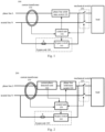
- FIG. 1 illustrates a schematic diagram of an apparatus 100 for generating a self-check leakage current according to an embodiment of the present disclosure.
- the load is supplied with electric energy through the phase line (Live wire) L and the neutral line (Neutral wire) N.
- the current flows from the phase line L to the load and from the load flows back to the neutral line N.
- the leakage generating apparatus 100 includes a mechanical switch 110, a phase line solid-state switch 120, a current transformer 130, a bypass unit 140 and a control unit 150.
- the mechanical switch 110 serves as an isolating switch for mechanically switching on and off the phase line L and the neutral line N at the same time.
- the phase line solid-state switch 120 is arranged on the phase line L and located upstream of the mechanical switch 110, i.e., arranged further away from the load relative to the mechanical switch 110.
- the current transformer is arranged upstream of the phase line solid-state switch 120, i.e., arranged further away from the load relative to the phase line solid-state switch 120.
- the phase line L and the neutral line N pass through the current transformer 130. Under normal situations, the currents flowing through the phase line L and the neutral line N are equal in magnitude and opposite in direction, so the resulting magnetomotive force is zero. The voltage thus induced by the current transformer 130 surrounding the phase line L and the neutral line N is zero.
- the bypass unit 140 includes a bypass switch 141 and a bypass resistor R connected in series. One end of the bypass unit 140 is connected between the mechanical switch 110 and the phase line solid-state switch 120 on the phase line L, and the other end is connected to the upstream of the current transformer 130 on the neutral line N, i.e., arranged further away from the load relative to the current transformer 130.
- the bypass unit 140 When the bypass switch 141 is switched on, the bypass unit 140 forms a new path with respect to a part of the neutral line N passing through the current transformer 130, so that all or part of the current flowing through the phase line L of the current transformer 130 can be prevented from passing through the current transformer 130 on the neutral line N.
- the control unit 150 is configured to control the switching on and off of the phase line solid-state switch 120 and the bypass switch 141, and to receive the current value detected by the current transformer 130.
- the self-check leakage current is generated when the phase line solid-state switch 120 and the bypass switch 141 are switched on.
- control unit 150 may determine whether the functions of the current transformer 130 and the phase line solid-state switch 120 are normal according to the self-check leakage current detected by the current transformer 130 when the self-check leakage current is generated.
- the apparatus for generating a self-check leakage current may generate the self-check leakage current to check whether the functions of the current transformer 130 and the phase line solid-state switch 120 are normal before supplying power to the load.
- the mechanical switch 110 when the mechanical switch 110 is to be closed to supply power to the load, the mechanical switch 110 sends a mechanical switch action signal to the control unit 150 before the mechanical switch 110 is closed, i.e., before the mechanical switch 110 reaches the dead point.
- the control unit 150 quickly switches on the phase line solid-state switch 120 and the bypass switch 141, thus forming a self-check leakage current loop.
- the current flows from the phase line L through the current transformer 130 and the phase line solid-state switch 120, and then flows back to the neutral line N through the bypass unit 140 and without also passing through the current transformer 130.
- the magnitude of the formed the self-check leakage current depends on the magnitude of the bypass resistor R in the bypass unit 140. If the current transformer 130 can detect the self-check leakage current, the control unit 150 can determine that the functions of the current transformer 130 are normal and the functions of the phase line solid-state switch 120 are normal.
- the control unit 150 switches off the bypass switch 141 and switches on the phase line solid-state switch 120 when the functions of the current transformer 130 and the phase line solid-state switch 120 are normal. Power can be supplied to the load normally after the mechanical switch 110 is completely closed. If the control unit 150 finds that the current transformer 130 does not detect the current or the detected current does not meet the preset value, it is determined that the current transformer 130 or the phase line solid-state switch 120 has a fault. In this case, the control unit 150 switches off the bypass switch 141 and the phase line solid-state switch 120 and sends out a fault indication signal, so as to indicate the operator not to continue closing the mechanical switch 110.
- the apparatus for generating a self-check leakage current may also periodically generate the self-check leakage current to check whether the functions of the current transformer 130 are normal during the power supply to the load.
- the mechanical switch 110 is kept in the closed state, and the phase line solid-state switch 120 is kept switching on.
- the control unit 150 switches on the bypass switch 141 for a short time.
- a part of the current flowing through the phase line L of the current transformer 130 is shunted back to the neutral line N by the bypass unit 140 without flowing through the current transformer 130, but the rest of the current flows to the load and returns to the neutral line N and flows through the current transformer N. Therefore, at the current transformer 130, the part of the current in the phase line L that is greater than the current in the neutral line N is equal to the shunt current flowing through the bypass unit 140.
- the shunt current can be detected by the current transformer 130 as a self-check leakage current.
- the control unit 150 determines that the functions of the current transformer 130 are normal, and switches off the bypass switch 141 to restore normal power supply. If the control unit 150 finds that the current transformer 130 does not detect the current or the detected current does not meet the preset value, it is determined that the current transformer 130 has a fault. In this case, the control unit 150 switches off the bypass switch 141 and the phase line solid-state switch 120 and sends out a fault indication signal, so as to indicate that the current transformer 130 has a fault or indicate the operator to open the mechanical switch 110.
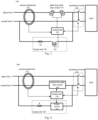
- FIG. 2 illustrates a schematic diagram of an apparatus 200 for generating a self-check leakage current according to another embodiment of the present disclosure.
- the apparatus 200 for generating a self-check leakage current is different from the apparatus 100 for generating a self-check leakage current shown in FIG. 1 in that an additional current phase detection unit 210.
- the current phase detection unit 210 is configured to detect the phase of the phase line current and to provide the phase to the control unit 150.
- the control unit 150 may switch on the bypass switch 141 according to the phase of the phase line current, so that the self-check leakage current has a predetermined initial phase.
- the control unit 150 may switch on the bypass switch 141 at the corresponding phase of 45°, 90° or 135°of the phase line current according to the phase of the phase line current detected by the current phase detection unit 210.
- Different initial phases of the self-check leakage current correspond to different current amplitudes, so the magnitude of the self-check leakage current, especially the instantaneous self-check leakage current, can be controlled by selecting to switch on the bypass switch 141 at different phases of the phase line current.
- FIG. 3 illustrates a schematic circuit diagram of an apparatus 300 for generating a self-check leakage current according to another embodiment of the present disclosure.
- the phase line solid-state switch 120 is constructed as two anti-series connected MOSFETs (Metal Oxide Semiconductor Field Effect Transistor).
- the MOSFET may be, e.g., a Si MOSFET (silicon MOSFET) or a SiC MOSFET (silicon carbide MOSFET).
- the phase line solid-state switch 120 can also be, e.g., constructed as a single IGBT (Insulated Gate Bipolar Transistor) or two anti-series connected IGBTs.
- the bypass switch 141 is constructed as an IGBT.
- the IGBT is especially a high-voltage resistant IGBT, e.g., it can withstand a short-circuit current for 40ms without requiring it to have a low conduction loss.
- the bypass switch 141 e.g., can also be constructed as a bidirectional thyristor (TRIAC) or a MOSFET, especially two anti-series connected MOSFETs.
- TRIAC bidirectional thyristor
- MOSFET especially two anti-series connected MOSFETs.
- FIG. 4 illustrates a schematic diagram of an apparatus 400 for generating a self-check leakage current according to another embodiment of the present disclosure.
- the load is supplied with electric energy through the phase line (Live wire) L and the neutral line (Neutral wire) N.
- the current flows from the phase line L to the load and from the load flows back to the neutral line N.
- the leakage generating apparatus 400 includes a mechanical switch 110, a neutral line solid-state switch 410, a current transformer 130, a bypass unit 140 and a control unit 150.
- the mechanical switch 110 serves as an isolating switch for mechanically switching on and off the phase line L and the neutral line N at the same time.
- the neutral line solid-state switch 410 is arranged on the neutral line N and located upstream of the mechanical switch 110.
- the current transformer is arranged upstream of the neutral line solid-state switch 410.
- the phase line L and the neutral line N pass through the current transformer 130.
- the bypass unit 140 includes a bypass switch 141 and a bypass resistor R connected in series. One end of the bypass unit 140 is connected between the mechanical switch 110 and the neutral line solid-state switch 410 on the neutral line N, and the other end is connected to the upstream of the current transformer 130 on the phase line L.
- the bypass unit 140 When the bypass switch 141 is switched on, the bypass unit 140 forms a new path with respect to a part of the phase line L passing through the current transformer 130, so that all or part of the current in the phase line L that has not flowed through the current transformer 130 can flow through the current transformer 130 on the neutral line N.
- the control unit 150 is configured to control the switching on and off of the neutral line solid-state switch 410 and the bypass switch 141, and to receive the current value detected by the current transformer 130.
- the self-check leakage current is generated when the neutral line solid-state switch 410 and the bypass switch 141 are switched on.
- control unit 150 may determine whether the functions of the current transformer 130 and the neutral line solid-state switch 410 are normal according to the self-check leakage current detected by the current transformer 130.
- the apparatus 400 for generating a self-check leakage current may generate the self-check leakage current to check whether the functions of the current transformer 130 and the neutral line solid-state switch 410 are normal before supplying power to the load.
- the mechanical switch 110 when the mechanical switch 110 is to be closed to supply power to the load, the mechanical switch 110 sends a mechanical switch action signal to the control unit 150 before the mechanical switch 110 is closed, i.e., before the mechanical switch 110 reaches the dead point.
- the control unit 150 quickly switches on the neutral line solid-state switch 410 and the bypass switch 141, thus forming a self-check leakage current loop.
- the current starts from the phase line L and does not flow through the current transformer 130, but reaches the neutral line N through the bypass unit 140, and then flows through the neutral line solid-state switch 410 and the current transformer 130.
- the magnitude of the formed self-check leakage current depends on the magnitude of the bypass resistor R in the bypass unit 140. If the current transformer 130 can detect the self-check leakage current, the control unit 150 can determine that the functions of the current transformer 130 are normal and the functions of the neutral line solid-state switch 410 are normal.
- the control unit 150 switches off the bypass switch 141 and switches on the neutral line solid-state switch 410 when the functions of the current transformer 130 and the neutral line solid-state switch 410 are normal. Power can be supplied to the load normally after the mechanical switch 110 is completely closed. If the control unit 150 finds that the current transformer 130 does not detect the current or the detected current does not meet the preset value, it is determined that the current transformer 130 or the neutral line solid-state switch 410 has a fault. In this case, the control unit 150 switches off the bypass switch 141 and the neutral line solid-state switch 410 and sends out a fault indication signal, so as to indicate the operator not to continue closing the mechanical switch 110.
- the apparatus 400 for generating a self-check leakage current may also periodically generate the self-check leakage current to check whether the functions of the current transformer 130 are normal during the power supply to the load.
- the mechanical switch 110 is kept in the closed state, and the neutral line solid-state switch 410 is kept switching on.
- the control unit 150 switches on the bypass switch 141 for a short time.
- a part of the current in the phase line L that does not flow through the current transformer 130 is shunted by the bypass unit 140 and flows back to the neutral line N, the rest of the current flows to the load and also returns to the neutral line N, and all the current in the neutral line flows through the current transformer 130. Therefore, at the current transformer 130, the part of the current in the phase line L that is less than the current in the neutral line N is equal to the shunt current flowing through the bypass unit 140.
- the shunt current can be detected by the current transformer 130 as a self-check leakage current.
- the control unit 150 determines that the functions of the current transformer 130 are normal, and switches off the bypass switch 141 to restore normal power supply. If the control unit 150 finds that the current transformer 130 does not detect the current or the detected current does not meet the preset value, it is determined that the current transformer 130 has a fault. In this case, the control unit 150 switches off the bypass switch 141 and the neutral line solid-state switch 410 and sends out a fault indication signal, so as to indicate that the current transformer 130 has a fault or indicate the operator to open the mechanical switch 110.
- the neutral line solid-state switch 410 may be constructed as two anti-series connected MOSFETs (Metal Oxide Semiconductor Field Effect Transistor).
- the MOSFET may be, e.g., a Si MOSFET (silicon MOSFET) or a SiC MOSFET (silicon carbide MOSFET).
- the neutral line solid-state switch 410 can also be, e.g., constructed as a single IGBT (Insulated Gate Bipolar Transistor) or two anti-series connected IGBTs.
- the apparatus for generating a self-check leakage current may also be a combination of FIG. 1 and FIG. 4 , i.e., the apparatus for generating a self-check leakage current includes both the phase line solid-state switch 120 and the neutral line solid-state switch 410.
- the bypass switch 141 can select to connect to the phase line and the neutral line either in the manner shown in FIG. 1 or in the manner shown in FIG. 4 .
- the control unit 150 controls the switching on and off of the phase line solid-state switch 120 and the bypass switch 141 in the manner shown in FIG. 1 , or controls the switching on and off of the neutral line solid-state switch 410 and the bypass switch 141 in the manner shown in FIG. 4 , so as to generate a self-check leakage current, thereby detecting whether the functions of the current transformer 130, the phase line solid-state switch 120 and the neutral line solid-state switch 410 are normal.
- the apparatus for generating a self-check leakage current according to the present disclosure can realize the functional detection of the phase line solid-state switch and the neutral line solid-state switch of the current transformer before supplying power to the load equipment, thus avoiding the safety problem that the functional detection can only be carried out after supplying power.
- the apparatus for generating a self-check leakage current according to the present disclosure can realize the periodic detection of the power transmission and distribution devices such as the current transformers during power supply by controlling the phase line solid-state switch or the neutral line solid-state switch and the bypass switch constructed as a solid-state switch.
- the apparatus for generating a self-check leakage current does not need to arrange additional windings on the current transformer or an additional leakage current generating circuit, and because there is no mechanical contact for switching the power supply circuit and the leakage current generating circuit, the reliability and service life of the whole apparatus are greatly improved.
- circuits, units, devices, apparatus, equipment and systems involved in the present disclosure are only as illustrative examples, and are not intended to require or imply that they must be connected, arranged and configured in the manner shown in the block diagram. As those skilled in the art will recognize, these circuits, units, devices, apparatus, equipment and systems can be connected, arranged and configured in any manner, as long as the desired purpose can be achieved.
- the circuits, units, devices and apparatus involved in the present disclosure can be realized in any suitable manner.
Landscapes
- Physics & Mathematics (AREA)
- General Physics & Mathematics (AREA)
- Engineering & Computer Science (AREA)
- Power Engineering (AREA)
- Emergency Protection Circuit Devices (AREA)
Abstract
An apparatus for generating a self-check leakage current is disclosed. The apparatus includes: a mechanical switch (110) which is configured to simultaneously switch on and off a phase line (L) and a neutral line (N); a phase line solid-state switch (120) arranged on a phase line (L) and located upstream of the mechanical switch (110); a current transformer (130) arranged upstream of the phase line solid-state switch (120), and the phase line (L) and neutral line (N) pass through the current transformer (130); a bypass unit (140) including a bypass switch (141) and a bypass resistor (R1) connected in series, one end of the bypass unit is connected between the mechanical switch and the solid-state switch on the phase line (L), and the other end is connected to the upstream of the current transformer on the neutral line (N); A control unit (150), which is configured to control the switching on and off of the phase line solid-state switch (120) and the bypass switch (141) and to receive the current value detected by the current transformer (130), wherein the self-check leakage current is generated when the phase line solid-state switch and the bypass switch are switched on.
Description
- The disclosure relates to apparatuses for generating a self-check leakage current.
- Getting an electric shock is very dangerous when using electrical equipment. To protect the safety of a person in time when leakage occurs, it is indispensable to install a leakage protection switch in low-voltage terminal distribution equipment. The leakage protection switch includes a circuit breaker and a leakage current detection and switch driving circuit. The leakage current protection switch realizes the leakage current detection function through the current transformer. Under normal situations, the currents flowing through the phase line (Live wire) and the neutral line (Neutral wire) for a load are equal in magnitude and opposite in direction, so the resulting magnetomotive force is zero. The voltage induced by the current transformer surrounding the phase line and the neutral line is zero. When leakage occurs in a customer, the leakage current flows to the ground, so the current in the phase line is shunted, so the current in the neutral line is smaller than the current in the phase line. Finally, the resulting magnetomotive force therefore is no longer zero, and the voltage induced by the current transformer is no longer zero, so it can be determined that there is a leakage current.
- To ensure the functions of the current transformer are normal, a specific leakage current can be injected into the current transformer regularly to realize self-check. However, in the distribution network so far, it is not possible to do a leakage self-check when the mechanical switch is switched off, because the mechanical switch is arranged upstream of the current transformer.
- An apparatus for generating a self-check leakage current based on the solid-state switch is disclosed in the present disclosure. With this apparatus, the leakage protection function of power distribution equipment can be periodically detected, and the leakage protection function can also be automatically checked before supplying power to load equipment.
- The present disclosure provides an apparatus for generating a self-check leakage current, which includes: a mechanical switch which is configured to simultaneously switch on and off a phase line and a neutral line; a phase line solid-state switch arranged on a phase line and located upstream of the mechanical switch; a current transformer arranged upstream of the phase line solid-state switch, and the phase line and a neutral line pass through the current transformer; a bypass unit comprising a bypass switch and a bypass resistor connected in series, one end of the bypass unit is connected between the mechanical switch and the phase line solid-state switch on the phase line, and the other end is connected to the upstream of the current transformer on the neutral line; A control unit, which is configured to control the switching on and off of the phase line solid-state switch and the bypass switch, and to receive the current value detected by the current transformer, wherein the self-check leakage current is generated when the phase line solid-state switch and the bypass switch are switched on.
- According to the embodiment of the present disclosure, in the apparatus for generating a self-check leakage current, in the case of generating the self-check leakage current, the control unit determines whether the functions of the current transformer and the phase line solid-state switch are normal according to the self-check leakage current detected by the current transformer.
- According to the embodiment of the present disclosure, in the apparatus for generating a self-check leakage current, the control unit switches off the bypass switch and switches on the phase line solid-state switch when the functions of the current transformer and the phase line solid-state switch are normal, otherwise, the control unit switches off the bypass switch and the phase line solid-state switch and sends out a fault indication signal.
- According to the embodiment of the present disclosure, in the apparatus for generating a self-check leakage current, before the mechanical switch is closed, the control unit switches on the phase line solid-state switch and the bypass switch.
- According to the embodiment of the present disclosure, in the apparatus for generating a self-check leakage current, before the mechanical switch is closed, the mechanical switch sends a mechanical switch action signal to the control unit, and the control unit switches on the phase line solid-state switch and the bypass switch according to the mechanical switch action signal.
- According to the embodiment of the present disclosure, in the apparatus for generating a self-check leakage current further includes: a current phase detection unit which is configured to detect a phase of a phase line current and to provide the phase to the control unit, wherein the control unit switches on the bypass switch according to the phase of the phase line current, so that the self-check leakage current has a predetermined initial phase.
- According to the embodiment of the present disclosure, in the apparatus for generating a self-check leakage current, the phase line solid-state switch is constructed as two anti-series connected MOSFETs.
- According to the embodiment of the present disclosure, in the apparatus for generating a self-check leakage current, the bypass switch is constructed as an IGBT.
- The embodiment of the present disclosure also provides an apparatus for generating a self-check leakage current, which includes: a mechanical switch which is configured to simultaneously switch on and off a phase line and a neutral line; a neutral line solid-state switch arranged on the neutral line and located between the mechanical switch and the current transformer; a current transformer arranged upstream of the phase line solid-state switch, and the phase line and a neutral line pass through the current transformer; a bypass unit comprising a bypass switch and a bypass resistor connected in series, one end of the bypass unit is connected to the upstream of the current transformer on the phase line, and the other end is connected between the mechanical switch and the phase line solid-state switch on the neutral line; A control unit, which is configured to control the switching on and off of the phase line solid-state switch and the bypass switch, and to receive the current value detected by the current transformer, wherein the self-check leakage current is generated when the phase line solid-state switch and the bypass switch are switched on.
- According to the embodiment of the present disclosure, in the apparatus for generating a self-check leakage current, in the case of generating the self-check leakage current, the control unit determines whether the functions of the current transformer and the neutral line solid-state switch are normal according to the self-check leakage current detected by the current transformer.
- The apparatus for generating a self-check leakage current according to the present disclosure can realize the functional detection of the phase line solid-state switch or the neutral line solid-state switch of the current transformer before supplying power to the load equipment, thus avoiding the safety problem that the functional detection can only be carried out after supplying power. On the other hand, the apparatus for generating a self-check leakage current according to the present disclosure can realize the periodic detection of the power transmission and distribution devices such as the current transformers during power supply by controlling the phase line solid-state switch or the neutral line solid-state switch and the bypass switch constructed as a solid-state switch. Compared with the existing apparatus for generating or injecting leakage current for self-checking, the apparatus for generating a self-check leakage current according to the present disclosure does not need to arrange additional windings on the current transformer or an additional leakage current generating circuit. The reliability and service life of the whole apparatus is greatly improved because there is no mechanical contact for switching the power supply circuit and the leakage current generating circuit.
- In order to explain the technical scheme of the embodiment of the present disclosure more clearly, the accompanying drawings needed in the description of the embodiment will be briefly introduced below. The accompanying drawings in the following description are only exemplary embodiments of the present disclosure.
-
FIG. 1 illustrates a schematic diagram of an apparatus for generating a self-check leakage current according to an embodiment of the present disclosure, -
FIG. 2 illustrates a schematic diagram of an apparatus for generating a self-check leakage current according to another embodiment of the present disclosure, -
FIG. 3 illustrates a schematic circuit diagram of an apparatus for generating a self-check leakage current according to another embodiment of the present disclosure, and -
FIG. 4 illustrates a schematic diagram of an apparatus for generating a self-check leakage current according to another embodiment of the present disclosure. - To make the objects, technical schemes and advantages of the present disclosure more obvious, exemplary embodiments according to the present disclosure will be described in detail below regarding the accompanying drawings. Obviously, the described embodiments are only a part of the embodiments of the present disclosure, not all the embodiments of the present disclosure. It should be understood that the present disclosure is not limited by the exemplary embodiments described herein.
- In this specification and the accompanying drawings, basically the same or similar steps and elements are denoted by the same or similar reference numerals, and repeated descriptions of these steps and elements will be omitted. Meanwhile, in the description of the present disclosure, the terms "first", "second" and so on are only used to distinguish descriptions, and cannot be understood as indicating or implying relative importance or order.
- In this specification and the accompanying drawings, according to the embodiments, elements are described in singular or plural forms. However, the singular and plural forms are appropriately selected for the presented situations only for the convenience of explanation and are not intended to limit the present disclosure. Therefore, the singular form can include the plural form, and the plural form can also include the singular form unless the context clearly indicates otherwise.
-
FIG. 1 illustrates a schematic diagram of anapparatus 100 for generating a self-check leakage current according to an embodiment of the present disclosure. As shown inFIG. 1 , the load is supplied with electric energy through the phase line (Live wire) L and the neutral line (Neutral wire) N. The current flows from the phase line L to the load and from the load flows back to the neutral line N. Theleakage generating apparatus 100 according to the present disclosure includes amechanical switch 110, a phase line solid-state switch 120, acurrent transformer 130, abypass unit 140 and acontrol unit 150. Themechanical switch 110 serves as an isolating switch for mechanically switching on and off the phase line L and the neutral line N at the same time. The phase line solid-state switch 120 is arranged on the phase line L and located upstream of themechanical switch 110, i.e., arranged further away from the load relative to themechanical switch 110. The current transformer is arranged upstream of the phase line solid-state switch 120, i.e., arranged further away from the load relative to the phase line solid-state switch 120. The phase line L and the neutral line N pass through thecurrent transformer 130. Under normal situations, the currents flowing through the phase line L and the neutral line N are equal in magnitude and opposite in direction, so the resulting magnetomotive force is zero. The voltage thus induced by thecurrent transformer 130 surrounding the phase line L and the neutral line N is zero. When leakage occurs on the load, the current in the neutral line is smaller than the current in the phase line due to the shunt of the leakage current. The resulting magnetomotive force therefore is no longer zero, and the voltage induced by thecurrent transformer 130 is no longer zero, so that it can be determined that there is a leakage. Thebypass unit 140 includes abypass switch 141 and a bypass resistor R connected in series. One end of thebypass unit 140 is connected between themechanical switch 110 and the phase line solid-state switch 120 on the phase line L, and the other end is connected to the upstream of thecurrent transformer 130 on the neutral line N, i.e., arranged further away from the load relative to thecurrent transformer 130. When thebypass switch 141 is switched on, thebypass unit 140 forms a new path with respect to a part of the neutral line N passing through thecurrent transformer 130, so that all or part of the current flowing through the phase line L of thecurrent transformer 130 can be prevented from passing through thecurrent transformer 130 on the neutral line N. Thecontrol unit 150 is configured to control the switching on and off of the phase line solid-state switch 120 and thebypass switch 141, and to receive the current value detected by thecurrent transformer 130. The self-check leakage current is generated when the phase line solid-state switch 120 and thebypass switch 141 are switched on. - In the embodiment according to the present disclosure, the
control unit 150 may determine whether the functions of thecurrent transformer 130 and the phase line solid-state switch 120 are normal according to the self-check leakage current detected by thecurrent transformer 130 when the self-check leakage current is generated. - For example, the apparatus for generating a self-check leakage current according to the present disclosure may generate the self-check leakage current to check whether the functions of the
current transformer 130 and the phase line solid-state switch 120 are normal before supplying power to the load. In the embodiment according to the present disclosure, when themechanical switch 110 is to be closed to supply power to the load, themechanical switch 110 sends a mechanical switch action signal to thecontrol unit 150 before themechanical switch 110 is closed, i.e., before themechanical switch 110 reaches the dead point. According to the mechanical switch action signal, thecontrol unit 150 quickly switches on the phase line solid-state switch 120 and thebypass switch 141, thus forming a self-check leakage current loop. In the self-check leakage current loop, the current flows from the phase line L through thecurrent transformer 130 and the phase line solid-state switch 120, and then flows back to the neutral line N through thebypass unit 140 and without also passing through thecurrent transformer 130. The magnitude of the formed the self-check leakage current depends on the magnitude of the bypass resistor R in thebypass unit 140. If thecurrent transformer 130 can detect the self-check leakage current, thecontrol unit 150 can determine that the functions of thecurrent transformer 130 are normal and the functions of the phase line solid-state switch 120 are normal. - In the embodiment according to the present disclosure, the
control unit 150 switches off thebypass switch 141 and switches on the phase line solid-state switch 120 when the functions of thecurrent transformer 130 and the phase line solid-state switch 120 are normal. Power can be supplied to the load normally after themechanical switch 110 is completely closed. If thecontrol unit 150 finds that thecurrent transformer 130 does not detect the current or the detected current does not meet the preset value, it is determined that thecurrent transformer 130 or the phase line solid-state switch 120 has a fault. In this case, thecontrol unit 150 switches off thebypass switch 141 and the phase line solid-state switch 120 and sends out a fault indication signal, so as to indicate the operator not to continue closing themechanical switch 110. - In addition, the apparatus for generating a self-check leakage current according to the present disclosure, e.g., may also periodically generate the self-check leakage current to check whether the functions of the
current transformer 130 are normal during the power supply to the load. In the embodiment according to the present disclosure, during the power supply to the load, themechanical switch 110 is kept in the closed state, and the phase line solid-state switch 120 is kept switching on. When it is necessary to check the functionality of thecurrent transformer 130, thecontrol unit 150 switches on thebypass switch 141 for a short time. In this case, a part of the current flowing through the phase line L of thecurrent transformer 130 is shunted back to the neutral line N by thebypass unit 140 without flowing through thecurrent transformer 130, but the rest of the current flows to the load and returns to the neutral line N and flows through the current transformer N. Therefore, at thecurrent transformer 130, the part of the current in the phase line L that is greater than the current in the neutral line N is equal to the shunt current flowing through thebypass unit 140. The shunt current can be detected by thecurrent transformer 130 as a self-check leakage current. - In the embodiment according to the present disclosure, in the case that the
current transformer 130 can detect the self-check leakage current, thecontrol unit 150 determines that the functions of thecurrent transformer 130 are normal, and switches off thebypass switch 141 to restore normal power supply. If thecontrol unit 150 finds that thecurrent transformer 130 does not detect the current or the detected current does not meet the preset value, it is determined that thecurrent transformer 130 has a fault. In this case, thecontrol unit 150 switches off thebypass switch 141 and the phase line solid-state switch 120 and sends out a fault indication signal, so as to indicate that thecurrent transformer 130 has a fault or indicate the operator to open themechanical switch 110. -
FIG. 2 illustrates a schematic diagram of anapparatus 200 for generating a self-check leakage current according to another embodiment of the present disclosure. Theapparatus 200 for generating a self-check leakage current is different from theapparatus 100 for generating a self-check leakage current shown inFIG. 1 in that an additional currentphase detection unit 210. The currentphase detection unit 210 is configured to detect the phase of the phase line current and to provide the phase to thecontrol unit 150. Thecontrol unit 150 may switch on thebypass switch 141 according to the phase of the phase line current, so that the self-check leakage current has a predetermined initial phase. For example, in the case that the self-check leakage current is expected to have an initial phase of 45°, 90° or 135°, thecontrol unit 150 may switch on thebypass switch 141 at the corresponding phase of 45°, 90° or 135°of the phase line current according to the phase of the phase line current detected by the currentphase detection unit 210. Different initial phases of the self-check leakage current correspond to different current amplitudes, so the magnitude of the self-check leakage current, especially the instantaneous self-check leakage current, can be controlled by selecting to switch on thebypass switch 141 at different phases of the phase line current. -
FIG. 3 illustrates a schematic circuit diagram of anapparatus 300 for generating a self-check leakage current according to another embodiment of the present disclosure. In theapparatus 300 for the self-check leakage current shown inFIG. 3 , the phase line solid-state switch 120 is constructed as two anti-series connected MOSFETs (Metal Oxide Semiconductor Field Effect Transistor). The MOSFET may be, e.g., a Si MOSFET (silicon MOSFET) or a SiC MOSFET (silicon carbide MOSFET). Furthermore, in the embodiment according to the present disclosure, the phase line solid-state switch 120 can also be, e.g., constructed as a single IGBT (Insulated Gate Bipolar Transistor) or two anti-series connected IGBTs. - In the
apparatus 300 for the self-check leakage current shown inFIG. 3 , thebypass switch 141 is constructed as an IGBT. The IGBT is especially a high-voltage resistant IGBT, e.g., it can withstand a short-circuit current for 40ms without requiring it to have a low conduction loss. Furthermore, in the embodiment according to the present disclosure, thebypass switch 141, e.g., can also be constructed as a bidirectional thyristor (TRIAC) or a MOSFET, especially two anti-series connected MOSFETs. -
FIG. 4 illustrates a schematic diagram of anapparatus 400 for generating a self-check leakage current according to another embodiment of the present disclosure. As shown inFIG. 4 , the load is supplied with electric energy through the phase line (Live wire) L and the neutral line (Neutral wire) N. The current flows from the phase line L to the load and from the load flows back to the neutral line N. Theleakage generating apparatus 400 according to the present disclosure includes amechanical switch 110, a neutral line solid-state switch 410, acurrent transformer 130, abypass unit 140 and acontrol unit 150. Themechanical switch 110 serves as an isolating switch for mechanically switching on and off the phase line L and the neutral line N at the same time. The neutral line solid-state switch 410 is arranged on the neutral line N and located upstream of themechanical switch 110. The current transformer is arranged upstream of the neutral line solid-state switch 410. The phase line L and the neutral line N pass through thecurrent transformer 130. Thebypass unit 140 includes abypass switch 141 and a bypass resistor R connected in series. One end of thebypass unit 140 is connected between themechanical switch 110 and the neutral line solid-state switch 410 on the neutral line N, and the other end is connected to the upstream of thecurrent transformer 130 on the phase line L. When thebypass switch 141 is switched on, thebypass unit 140 forms a new path with respect to a part of the phase line L passing through thecurrent transformer 130, so that all or part of the current in the phase line L that has not flowed through thecurrent transformer 130 can flow through thecurrent transformer 130 on the neutral line N. Thecontrol unit 150 is configured to control the switching on and off of the neutral line solid-state switch 410 and thebypass switch 141, and to receive the current value detected by thecurrent transformer 130. The self-check leakage current is generated when the neutral line solid-state switch 410 and thebypass switch 141 are switched on. - In the embodiment according to the present disclosure, in the case that the self-check leakage current is generated, the
control unit 150 may determine whether the functions of thecurrent transformer 130 and the neutral line solid-state switch 410 are normal according to the self-check leakage current detected by thecurrent transformer 130. - For example, the
apparatus 400 for generating a self-check leakage current according to the present disclosure may generate the self-check leakage current to check whether the functions of thecurrent transformer 130 and the neutral line solid-state switch 410 are normal before supplying power to the load. In the embodiment according to the present disclosure, when themechanical switch 110 is to be closed to supply power to the load, themechanical switch 110 sends a mechanical switch action signal to thecontrol unit 150 before themechanical switch 110 is closed, i.e., before themechanical switch 110 reaches the dead point. According to the mechanical switch action signal, thecontrol unit 150 quickly switches on the neutral line solid-state switch 410 and thebypass switch 141, thus forming a self-check leakage current loop. In the self-check leakage current loop, the current starts from the phase line L and does not flow through thecurrent transformer 130, but reaches the neutral line N through thebypass unit 140, and then flows through the neutral line solid-state switch 410 and thecurrent transformer 130. The magnitude of the formed self-check leakage current depends on the magnitude of the bypass resistor R in thebypass unit 140. If thecurrent transformer 130 can detect the self-check leakage current, thecontrol unit 150 can determine that the functions of thecurrent transformer 130 are normal and the functions of the neutral line solid-state switch 410 are normal. - In the embodiment according to the present disclosure, the
control unit 150 switches off thebypass switch 141 and switches on the neutral line solid-state switch 410 when the functions of thecurrent transformer 130 and the neutral line solid-state switch 410 are normal. Power can be supplied to the load normally after themechanical switch 110 is completely closed. If thecontrol unit 150 finds that thecurrent transformer 130 does not detect the current or the detected current does not meet the preset value, it is determined that thecurrent transformer 130 or the neutral line solid-state switch 410 has a fault. In this case, thecontrol unit 150 switches off thebypass switch 141 and the neutral line solid-state switch 410 and sends out a fault indication signal, so as to indicate the operator not to continue closing themechanical switch 110. - In addition, the
apparatus 400 for generating a self-check leakage current according to the present disclosure, e.g., may also periodically generate the self-check leakage current to check whether the functions of thecurrent transformer 130 are normal during the power supply to the load. In the embodiment according to the present disclosure, during the power supply to the load, themechanical switch 110 is kept in the closed state, and the neutral line solid-state switch 410 is kept switching on. When it is necessary to check the functionality of thecurrent transformer 130, thecontrol unit 150 switches on thebypass switch 141 for a short time. In this case, a part of the current in the phase line L that does not flow through thecurrent transformer 130 is shunted by thebypass unit 140 and flows back to the neutral line N, the rest of the current flows to the load and also returns to the neutral line N, and all the current in the neutral line flows through thecurrent transformer 130. Therefore, at thecurrent transformer 130, the part of the current in the phase line L that is less than the current in the neutral line N is equal to the shunt current flowing through thebypass unit 140. The shunt current can be detected by thecurrent transformer 130 as a self-check leakage current. - In the embodiment according to the present disclosure, in the case that the
current transformer 130 can detect the self-check leakage current, thecontrol unit 150 determines that the functions of thecurrent transformer 130 are normal, and switches off thebypass switch 141 to restore normal power supply. If thecontrol unit 150 finds that thecurrent transformer 130 does not detect the current or the detected current does not meet the preset value, it is determined that thecurrent transformer 130 has a fault. In this case, thecontrol unit 150 switches off thebypass switch 141 and the neutral line solid-state switch 410 and sends out a fault indication signal, so as to indicate that thecurrent transformer 130 has a fault or indicate the operator to open themechanical switch 110. - According to the embodiment of the present disclosure, the neutral line solid-
state switch 410 may be constructed as two anti-series connected MOSFETs (Metal Oxide Semiconductor Field Effect Transistor). The MOSFET may be, e.g., a Si MOSFET (silicon MOSFET) or a SiC MOSFET (silicon carbide MOSFET). Furthermore, in the embodiment according to the present disclosure, the neutral line solid-state switch 410 can also be, e.g., constructed as a single IGBT (Insulated Gate Bipolar Transistor) or two anti-series connected IGBTs. - According to the embodiment of the present disclosure, the apparatus for generating a self-check leakage current may also be a combination of
FIG. 1 andFIG. 4 , i.e., the apparatus for generating a self-check leakage current includes both the phase line solid-state switch 120 and the neutral line solid-state switch 410. Thebypass switch 141 can select to connect to the phase line and the neutral line either in the manner shown inFIG. 1 or in the manner shown inFIG. 4 . Accordingly, thecontrol unit 150 controls the switching on and off of the phase line solid-state switch 120 and thebypass switch 141 in the manner shown inFIG. 1 , or controls the switching on and off of the neutral line solid-state switch 410 and thebypass switch 141 in the manner shown inFIG. 4 , so as to generate a self-check leakage current, thereby detecting whether the functions of thecurrent transformer 130, the phase line solid-state switch 120 and the neutral line solid-state switch 410 are normal. - The apparatus for generating a self-check leakage current according to the present disclosure, on the one hand, can realize the functional detection of the phase line solid-state switch and the neutral line solid-state switch of the current transformer before supplying power to the load equipment, thus avoiding the safety problem that the functional detection can only be carried out after supplying power. On the other hand, the apparatus for generating a self-check leakage current according to the present disclosure can realize the periodic detection of the power transmission and distribution devices such as the current transformers during power supply by controlling the phase line solid-state switch or the neutral line solid-state switch and the bypass switch constructed as a solid-state switch. Compared with the existing apparatus for generating or injecting leakage current for self-checking, the apparatus for generating a self-check leakage current according to the present disclosure does not need to arrange additional windings on the current transformer or an additional leakage current generating circuit, and because there is no mechanical contact for switching the power supply circuit and the leakage current generating circuit, the reliability and service life of the whole apparatus are greatly improved.
- The block diagrams of circuits, units, devices, apparatus, equipment and systems involved in the present disclosure are only as illustrative examples, and are not intended to require or imply that they must be connected, arranged and configured in the manner shown in the block diagram. As those skilled in the art will recognize, these circuits, units, devices, apparatus, equipment and systems can be connected, arranged and configured in any manner, as long as the desired purpose can be achieved. The circuits, units, devices and apparatus involved in the present disclosure can be realized in any suitable manner.
- It should be understood by those skilled in the art that the above-mentioned specific embodiments are only examples rather than limitations, and various modifications, combinations, partial combinations and substitutions can be made to the embodiments of the present disclosure according to design requirements and other factors, as long as they are within the scope of the appended claims or their equivalents, i.e., they belong to the scope of rights to be protected by the present disclosure.
Claims (10)
- An apparatus for generating a self-check leakage current, comprising:A mechanical switch which is configured to simultaneously switch on and off a phase line and a neutral line,A phase line solid-state switch arranged on the phase line and located upstream of the mechanical switch,A current transformer arranged upstream of the phase line solid-state switch, and the phase line and a neutral line pass through the current transformer,A bypass unit comprising a bypass switch and a bypass resistor connected in series, one end of the bypass unit is connected between the mechanical switch and the phase line solid-state switch on the phase line, and the other end is connected to the upstream of the current transformer on the neutral line,A control unit, which is configured to control the switching on and off of the phase line solid-state switch and the bypass switch, and to receive the current value detected by the current transformer,Wherein the self-check leakage current is generated when the phase line solid-state switch and the bypass switch are switched on.
- The apparatus for generating a self-check leakage current according to claim 1, wherein in the case of generating the self-check leakage current, the control unit determines whether the functions of the current transformer and the phase line solid-state switch are normal according to the self-check leakage current detected by the current transformer.
- The apparatus for generating a self-check leakage current according to claim 2, wherein the control unit switches off the bypass switch and switches on the phase line solid-state switch when the functions of the current transformer and the phase line solid-state switch are normal, otherwise, the control unit switches off the bypass switch and the phase line solid-state switch and sends out a fault indication signal.
- The apparatus for generating a self-check leakage current according to claim 1, wherein before the mechanical switch is closed, the control unit switches on the phase line solid-state switch and the bypass switch.
- The apparatus for generating a self-check leakage current according to claim 4, wherein before the mechanical switch is closed, the mechanical switch sends a mechanical switch action signal to the control unit, and the control unit switches on the phase line solid-state switch and the bypass switch according to the mechanical switch action signal.
- The apparatus for generating a self-check leakage current according to claim 1, further comprising:A current phase detection unit which is configured to detect a phase of a phase line current and to provide the phase to the control unit,Wherein the control unit switches on the bypass switch according to the phase of the phase line current, so that the self-check leakage current has a predetermined initial phase.
- The apparatus for generating a self-check leakage current according to claim 1, wherein the phase line solid-state switch is constructed as two anti-series connected MOSFET.
- The apparatus for generating a self-check leakage current according to claim 1, wherein the bypass switch is constructed as an IGBT.
- An apparatus for generating a self-check leakage current, comprising:A mechanical switch which is configured to simultaneously switch on and off a phase line and a neutral line,A neutral line solid-state switch arranged on the neutral line and located between the mechanical switch and the current transformer,A current transformer arranged upstream of the phase line solid-state switch, and the phase line and a neutral line pass through the current transformer,A bypass unit comprising a bypass switch and a bypass resistor connected in series, one end of the bypass unit is connected to the upstream of the current transformer on the phase line, and the other end is connected between the mechanical switch and the phase line solid-state switch on the neutral line,A control unit which is configured to control the switching on and off of the phase line solid-state switch and the bypass switch, and to receive the current value detected by the current transformer,Wherein the self-check leakage current is generated when the phase line solid-state switch and the bypass switch are switched on.
- The apparatus for generating a self-check leakage current according to claim 9, wherein in the case of generating the self-check leakage current, the control unit determines whether the functions of the current transformer and the neutral line solid-state switch are normal according to the self-check leakage current detected by the current transformer.
Applications Claiming Priority (1)
| Application Number | Priority Date | Filing Date | Title |
|---|---|---|---|
| CN202310402971.8A CN118801293A (en) | 2023-04-14 | 2023-04-14 | Device for generating self-detection leakage current |
Publications (1)
| Publication Number | Publication Date |
|---|---|
| EP4447246A1 true EP4447246A1 (en) | 2024-10-16 |
Family
ID=89119550
Family Applications (1)
| Application Number | Title | Priority Date | Filing Date |
|---|---|---|---|
| EP23307046.5A Pending EP4447246A1 (en) | 2023-04-14 | 2023-11-24 | Apparatus for generating a self-check leakage current |
Country Status (3)
| Country | Link |
|---|---|
| US (1) | US12535540B2 (en) |
| EP (1) | EP4447246A1 (en) |
| CN (1) | CN118801293A (en) |
Citations (5)
| Publication number | Priority date | Publication date | Assignee | Title |
|---|---|---|---|---|
| US20090251148A1 (en) * | 2004-06-15 | 2009-10-08 | Pass & Seymour, Inc. | Protective Device with End-Of-Life Indication Before Power Denial |
| US9118172B2 (en) * | 2003-10-17 | 2015-08-25 | Pass & Seymour, Inc. | Protective device with automated self test |
| EP3012853B1 (en) * | 2014-10-26 | 2019-06-05 | Semiconductor Components Industries, LLC | Electrical safety device miswire detection |
| DE102019213604A1 (en) * | 2019-09-06 | 2021-03-11 | Siemens Aktiengesellschaft | Circuit breaker, circuit breaker system and process |
| WO2023280730A1 (en) * | 2021-07-05 | 2023-01-12 | Phoenix Contact Gmbh & Co.Kg | Residual current monitoring for a dc voltage switching device |
Family Cites Families (3)
| Publication number | Priority date | Publication date | Assignee | Title |
|---|---|---|---|---|
| US4763013A (en) * | 1987-09-21 | 1988-08-09 | American Telephone And Telegraph Company, At&T Bell Laboratories | Backup protection switch to prevent reverse power flow in a UPS |
| US11114257B2 (en) * | 2018-04-06 | 2021-09-07 | Yazaki North America, Inc. | Methods and apparatus for DC arc detection/suppression |
| KR102656808B1 (en) * | 2021-03-29 | 2024-04-12 | 엘에스일렉트릭(주) | Solid state circuit breaker(sscb) |
-
2023
- 2023-04-14 CN CN202310402971.8A patent/CN118801293A/en active Pending
- 2023-11-24 EP EP23307046.5A patent/EP4447246A1/en active Pending
- 2023-11-27 US US18/520,397 patent/US12535540B2/en active Active
Patent Citations (5)
| Publication number | Priority date | Publication date | Assignee | Title |
|---|---|---|---|---|
| US9118172B2 (en) * | 2003-10-17 | 2015-08-25 | Pass & Seymour, Inc. | Protective device with automated self test |
| US20090251148A1 (en) * | 2004-06-15 | 2009-10-08 | Pass & Seymour, Inc. | Protective Device with End-Of-Life Indication Before Power Denial |
| EP3012853B1 (en) * | 2014-10-26 | 2019-06-05 | Semiconductor Components Industries, LLC | Electrical safety device miswire detection |
| DE102019213604A1 (en) * | 2019-09-06 | 2021-03-11 | Siemens Aktiengesellschaft | Circuit breaker, circuit breaker system and process |
| WO2023280730A1 (en) * | 2021-07-05 | 2023-01-12 | Phoenix Contact Gmbh & Co.Kg | Residual current monitoring for a dc voltage switching device |
Also Published As
| Publication number | Publication date |
|---|---|
| CN118801293A (en) | 2024-10-18 |
| US20240345179A1 (en) | 2024-10-17 |
| US12535540B2 (en) | 2026-01-27 |
Similar Documents
| Publication | Publication Date | Title |
|---|---|---|
| US12034292B2 (en) | Adjustable speed drive with integrated solid-state circuit breaker and method of operation thereof | |
| CN105493218B (en) | circuit breaker with hybrid switch | |
| US9972997B2 (en) | Circuit interruption device | |
| ES2922103T3 (en) | Procedure for the control of a DC switch, DC switch and DC voltage system | |
| CN111869029B (en) | Circuit breaker control module | |
| US11159007B2 (en) | Electric circuit device with a residual current monitoring module for detecting a closed switch contact as well as a protection ground conductor interruption in a one or multiphase electric supply line | |
| US20120299393A1 (en) | Device and method to break the current of a power transmission or distribution line and current limiting arrangement | |
| US11588321B2 (en) | Low-voltage protection switch unit | |
| WO2011116832A1 (en) | A hybrid circuit breaker | |
| JP2016213179A (en) | DC circuit breaker and method of use | |
| ES2963812T3 (en) | Impedance for controlling AC fault currents in an HVDC high voltage to direct current converter | |
| JP2016127026A (en) | DC circuit breaker and method of breaking the same | |
| KR101821439B1 (en) | Fault current limiter | |
| JP2023092522A (en) | hybrid circuit breaker | |
| CN111937110A (en) | Switching device | |
| CN110036547A (en) | Under-voltage circuit breaker equipment | |
| US12062908B2 (en) | Static DC current-limiting switching system | |
| CN118074063A (en) | Circuit breaker with overvoltage protection and related circuit breaking method | |
| CN105206449B (en) | Make the apparatus and method and current limliting arrangement of the current interruption of transmission line of electricity or distribution line | |
| WO2015090365A1 (en) | Integrated series converter and circuit breaker in a power system | |
| WO2019086058A1 (en) | The method of connection to limit the value of voltage between the neutral point and ground in an alternating current electric network | |
| US12535540B2 (en) | Apparatus for generating a self-check leakage current | |
| US12212233B2 (en) | Switching device for a DC voltage circuit | |
| CN104885363A (en) | Semiconductor switch arrangement |
Legal Events
| Date | Code | Title | Description |
|---|---|---|---|
| PUAI | Public reference made under article 153(3) epc to a published international application that has entered the european phase |
Free format text: ORIGINAL CODE: 0009012 |
|
| STAA | Information on the status of an ep patent application or granted ep patent |
Free format text: STATUS: THE APPLICATION HAS BEEN PUBLISHED |
|
| AK | Designated contracting states |
Kind code of ref document: A1 Designated state(s): AL AT BE BG CH CY CZ DE DK EE ES FI FR GB GR HR HU IE IS IT LI LT LU LV MC ME MK MT NL NO PL PT RO RS SE SI SK SM TR |
|
| STAA | Information on the status of an ep patent application or granted ep patent |
Free format text: STATUS: REQUEST FOR EXAMINATION WAS MADE |
|
| 17P | Request for examination filed |
Effective date: 20250327 |