EP4447236A1 - Connector housing, mating connector housing assembly and connector assembly - Google Patents
Connector housing, mating connector housing assembly and connector assembly Download PDFInfo
- Publication number
- EP4447236A1 EP4447236A1 EP24169192.2A EP24169192A EP4447236A1 EP 4447236 A1 EP4447236 A1 EP 4447236A1 EP 24169192 A EP24169192 A EP 24169192A EP 4447236 A1 EP4447236 A1 EP 4447236A1
- Authority
- EP
- European Patent Office
- Prior art keywords
- tooth
- connector housing
- slot
- blocking part
- peripheral wall
- Prior art date
- Legal status (The legal status is an assumption and is not a legal conclusion. Google has not performed a legal analysis and makes no representation as to the accuracy of the status listed.)
- Pending
Links
Images



Classifications
-
- H—ELECTRICITY
- H01—ELECTRIC ELEMENTS
- H01R—ELECTRICALLY-CONDUCTIVE CONNECTIONS; STRUCTURAL ASSOCIATIONS OF A PLURALITY OF MUTUALLY-INSULATED ELECTRICAL CONNECTING ELEMENTS; COUPLING DEVICES; CURRENT COLLECTORS
- H01R13/00—Details of coupling devices of the kinds covered by groups H01R12/70 or H01R24/00 - H01R33/00
- H01R13/62—Means for facilitating engagement or disengagement of coupling parts or for holding them in engagement
- H01R13/629—Additional means for facilitating engagement or disengagement of coupling parts, e.g. aligning or guiding means, levers, gas pressure electrical locking indicators, manufacturing tolerances
- H01R13/62933—Comprising exclusively pivoting lever
- H01R13/62944—Pivoting lever comprising gear teeth
-
- H—ELECTRICITY
- H01—ELECTRIC ELEMENTS
- H01R—ELECTRICALLY-CONDUCTIVE CONNECTIONS; STRUCTURAL ASSOCIATIONS OF A PLURALITY OF MUTUALLY-INSULATED ELECTRICAL CONNECTING ELEMENTS; COUPLING DEVICES; CURRENT COLLECTORS
- H01R13/00—Details of coupling devices of the kinds covered by groups H01R12/70 or H01R24/00 - H01R33/00
- H01R13/46—Bases; Cases
- H01R13/52—Dustproof, splashproof, drip-proof, waterproof, or flameproof cases
- H01R13/5202—Sealing means between parts of housing or between housing part and a wall, e.g. sealing rings
-
- H—ELECTRICITY
- H01—ELECTRIC ELEMENTS
- H01R—ELECTRICALLY-CONDUCTIVE CONNECTIONS; STRUCTURAL ASSOCIATIONS OF A PLURALITY OF MUTUALLY-INSULATED ELECTRICAL CONNECTING ELEMENTS; COUPLING DEVICES; CURRENT COLLECTORS
- H01R13/00—Details of coupling devices of the kinds covered by groups H01R12/70 or H01R24/00 - H01R33/00
- H01R13/46—Bases; Cases
- H01R13/52—Dustproof, splashproof, drip-proof, waterproof, or flameproof cases
- H01R13/5219—Sealing means between coupling parts, e.g. interfacial seal
Definitions
- the present invention relates to a connector housing, a mating connector housing assembly, and a connector assembly comprising the connector housing and the mating connector housing assembly.
- a rack part is usually formed on the outer surface of the connector housing, and adjacent first and second tooth slots are formed on the rack part.
- a locking rod is rotatably installed on the mating connector housing; a gear part formed on the locking rod.
- a first tooth and a second tooth are formed on the gear part for respectively meshing with the first tooth slot and the second tooth slot.
- the present invention has been made to overcome or alleviate at least one aspect of the above mentioned disadvantages.
- a connector housing comprising of a peripheral wall; and a rack part formed on the outer surface of the peripheral wall.
- the rack part has opposite inner and outer sides in its width direction, and the inner side of the rack part is connected to the peripheral wall; the rack part has adjacent first and second tooth slots in its length direction, and the first and second tooth slots are used to respectively mesh with first and second teeth on a gear part of a mating connector.
- the slot width of the second tooth slot in the width direction is smaller than that of the first tooth slot to prevent the first tooth with a tooth width larger than the slot width of the second tooth slot from being incorrectly engaged in the second tooth slot.
- a blocking part is formed on the outer surface of the peripheral wall, and at least a portion of the blocking part is located in the second tooth slot, so that the slot width of the second tooth slot is smaller than that of the first tooth slot.
- the first tooth slot extends from the outer side surface of the rack part to the outer surface of the peripheral wall in the width direction, so that the slot width of the first tooth slot is equal to the width of the rack part.
- the blocking part has opposite inner and outer sides in the width direction, and the inner side of the blocking part is connected to the peripheral wall; the second tooth slot extends from the outer side surface of the rack part to the outer side surface of the blocking part in the width direction, so that the slot width of the second tooth slot is smaller than the width of the rack part.
- the peripheral wall has two opposite side walls in the width direction, the rack part protrudes from the side wall of the peripheral wall, and the outer surface of the side wall, the outer side surface of the rack part, and the outer side surface of the blocking part are parallel to each other.
- the blocking part extends along the height direction of the rack part beyond the opening of the second tooth slot to block the first tooth from the outside of the opening of the second tooth slot.
- the height of the blocking part extending upwards from the opening of the second tooth slot is not less than the tooth height of the first tooth and the second tooth.
- the blocking part has a front side surface and a rear side surface opposite to each other in the length direction, and the rear side surface of the blocking part is adjacent to the first tooth slot; the front side surface of the blocking part extends vertically along the height direction to block the first tooth from crossing over the blocking part backwards; the rear side surface of the blocking part is inclined relative to the height direction to allow the first tooth to cross over the blocking part forward.
- the height of the blocking part extending upwards from the opening of the second tooth slot is smaller than the tooth height of the first tooth and the second tooth.
- the blocking part has a front side surface and a rear side surface opposite to each other in the length direction, and the rear side surface of the blocking part is adjacent to the first tooth slot; the front side surface of the blocking part is inclined relative to the height direction to allow the first tooth to cross over the blocking part backwards; the rear side surface of the blocking part is inclined relative to the height direction to allow the first tooth to cross over the blocking part forward.
- a mating connector housing assembly comprises of a mating connector housing suitable for mating with the above connector housing; and a locking rod which is rotatably installed on the mating connector housing and can be rotated between a pre lock position and a final lock position.
- a gear part is formed on the locking rod, which has adjacent first and second teeth in its circumferential direction, and the tooth widths of the first and second teeth are respectively equal to the slot widths of the first and second tooth slots on the rack part.
- the first tooth and the second tooth are in positions corresponding to the first tooth slot and the second tooth slot respectively, to allow the first tooth and the second tooth to mesh with the first tooth slot and the second tooth slot, respectively; when the locking rod is rotated from the pre lock position to the final lock position, the first tooth and the second tooth engage with the first tooth slot and the second tooth slot respectively, to lock the connector housing and the mating connector housing in a mating state.
- the locking rod comprises of a lever portion having a connecting end; the gear part connected to the connecting end; and a shaft part axially connected between the connecting end and the gear part.
- a pivot hole is formed in the mating connector housing, and the shaft part of the locking rod is rotatably installed in the pivot hole.
- an installation portion is formed on the outer peripheral wall of the mating connector housing, the installation portion comprises a support plate, and the pivot hole is formed in the support plate; a mounting notch is formed on the support plate in communication with the pivot hole, and the shaft part is installed into the pivot hole through the mounting notch.
- the outer side surface of the support plate is against the connecting end of the lever portion, and the inner side surface of the support plate is against the end face of the gear part to prevent axial movement of the gear part relative to the support plate.
- the gear part comprises a wheel axle part, which is connected to the connecting end of the lever portion; the first tooth and the second tooth are formed on the outer peripheral surface of the wheel axle part.
- the first tooth and the second tooth each has opposite sides in the axial direction of the wheel axle part;
- the gear part further comprises a web plate radially extending from the wheel axle part, the web plate is connected to one sides of the first tooth and the second tooth; the distance from the other side of the first tooth to the web plate is greater than the distance from the other side of the second tooth to the web plate, so that the tooth width of the first tooth is greater than that of the second tooth.
- a connector assembly comprising a connector and a mating connector.
- the connector comprises of the connector housing; and a terminal provided in the connector housing.
- the mating connector comprises of the mating connector housing assembly; and a mating terminal provided in the mating connector housing and mated with the terminal.
- a flange portion is formed on the peripheral wall of the connector housing, and the flange portion is used to be fixed to a mounting panel to install the connector housing onto the mounting panel; the connector further comprises a first sealing ring arranged on the flange portion, which is suitable for being axially compressed between the flange portion and the mounting panel to achieve sealing between the two.
- the mating connector housing comprises of an outer peripheral wall; and a terminal holder which is connected to the outer peripheral wall and extends out of one end of the outer peripheral wall.
- the terminal holder is used to hold the mating terminal and is adapted to be inserted into the connector housing.
- an annular groove is formed between the outer peripheral wall and the terminal holder of the mating connector housing; the mating connector further comprises a second sealing ring, which is provided in the annular groove and axially compressed between the connector housing and the mating connector housing to achieve sealing between the two.
- the slot width of the second tooth slot on the rack part is smaller than the tooth width of the first tooth slot, and the tooth widths of the first and second teeth on the gear part are respectively equal to the slot widths of the first and second teeth on the rack part. Therefore, the present invention can prevent the first tooth on the gear part from being wrongly meshed into the second tooth slot on the rack part, thereby effectively avoiding mis operation.
- a connector housing comprising of a peripheral wall; and a rack part formed on the outer surface of the peripheral wall.
- the rack part has opposite inner and outer sides in its width direction, and the inner side of the rack part is connected to the peripheral wall; the rack part has adjacent first and second tooth slots in its length direction, and the first and second tooth slots are used to respectively mesh with first and second teeth on a gear part of a mating connector.
- the slot width of the second tooth slot in the width direction is smaller than that of the first tooth slot to prevent the first tooth with a tooth width larger than the slot width of the second tooth slot from being incorrectly engaged in the second tooth slot.
- a mating connector housing assembly comprises of: a mating connector housing suitable for mating with the above connector housing; and a locking rod which is rotatably installed on the mating connector housing and can be rotated between a pre lock position and a final lock position.
- a gear part is formed on the locking rod, which has adjacent first and second teeth in its circumferential direction, and the tooth widths of the first and second teeth are respectively equal to the slot widths of the first and second tooth slots on the rack part.
- the first tooth and the second tooth are in positions corresponding to the first tooth slot and the second tooth slot respectively, to allow the first tooth and the second tooth to mesh with the first tooth slot and the second tooth slot, respectively; when the locking rod is rotated from the pre lock position to the final lock position, the first tooth and the second tooth engage with the first tooth slot and the second tooth slot respectively, to lock the connector housing and the mating connector housing in a mating state.
- a connector assembly comprising a connector and a mating connector.
- the connector comprises of the connector housing; and a terminal provided in the connector housing.
- the mating connector comprises of: the mating connector housing assembly; and a mating terminal provided in the mating connector housing and mated with the terminal.
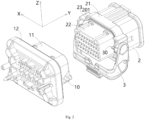
- Figure 1 shows an illustrative perspective view of a connector assembly according to an exemplary embodiment of the present invention
- Figure 2 shows an illustrative exploded view of a connector assembly according to an exemplary embodiment of the present invention
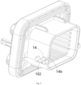
- Figure 3 shows an illustrative perspective view of a connector housing according to an exemplary embodiment of the present invention.
- a connector housing 1 is disclosed.
- the connector housing 1 mainly includes a peripheral wall 11 and a rack part 10.
- the rack part 10 is formed on the outer surface of the peripheral wall 11.
- the rack part 10 has opposite inner and outer sides in its width direction X, and the inner side of the rack part 10 is connected to the peripheral wall 11.
- the rack part 10 has a first tooth slot 101 and a second tooth slot 102 adjacent to each other in a length direction Y of the rack part 10.
- Figure 4 shows an illustrative perspective view of a mating connector housing assembly according to an exemplary embodiment of the present invention
- Figure 5 shows an illustrative perspective view of the mating connector housing 2 according to an exemplary embodiment of the present invention
- Figure 6 shows an illustrative perspective view of the locking rod 3 of the mating connector according to an exemplary embodiment of the present invention when viewed from one side
- Figure 7 shows an illustrative perspective view of the locking rod 3 of the mating connector according to an exemplary embodiment of the present invention when viewed from the other side
- Figure 8 shows a cross-sectional view of a connector assembly according to an exemplary embodiment of the present invention, wherein the locking rod 3 is in a pre lock position.
- the first tooth slot 101 and the second tooth slot 102 on the rack part 10 are used to mesh with the first tooth 301 and the second tooth 302 on the gear part 30 of the mating connector, respectively.
- the slot width of the second tooth slot 102 in the width direction X is smaller than that of the first tooth slot 101, in order to prevent the first tooth 301 with a tooth width larger than the slot width of the second tooth slot 102 from being wrongly engaged in the second tooth slot 102.
- a blocking part 14 is formed on the outer surface of the peripheral wall 11 of the connector housing 1. At least a portion of the blocking part 14 is located in the second tooth slot 102, so that the slot width of the second tooth slot 102 is smaller than that of the first tooth slot 101.
- the first tooth slot 101 extends from the outer side surface 10a of the rack part 10 to the outer surface of the peripheral wall 11 in the width direction X, so that the slot width of the first tooth slot 101 is equal to the width of the rack part 10.
- the blocking part 14 has opposite inner and outer sides in the width direction X, and the inner side of the blocking part 14 is connected to the peripheral wall 11.
- the second tooth slot 102 extends from the outer side surface 10a of the rack part 10 to the outer side surface 14a of the blocking part 14 in the width direction X, so that the slot width of the second tooth slot 102 is smaller than the width of the rack part 10.
- the peripheral wall 11 of the connector housing 1 has two opposite side walls 11a in the width direction X.
- the rack part 10 protrudes from the side wall 11a of the peripheral wall 11, and the outer surface of the side wall 11a, the outer side surface 10a of the rack part 10, and the outer side surface 14a of the blocking part 14 are parallel to each other.
- the blocking part 14 extends along the height direction Z of the rack part 10 beyond the opening of the second tooth slot 102 to block the first tooth 301 outside the opening of the second tooth slot 102.
- the height of the blocking part 14 extending upwards from the opening of the second tooth slot 102 is not less than the tooth height of the first tooth 301 and the second tooth 302.
- the blocking part 14 has a front side surface 14b and a rear side surface 14c opposite to each other in the length direction Y, and the rear side surface 14c of the blocking part 14 is adjacent to the first tooth slot 101.
- the front side surface 14b of the blocking part 14 extends vertically along the height direction Z to block the first tooth 301 from crossing over the blocking part 14 backwards.
- the rear side surface 14c of the blocking part 14 is inclined relative to the height direction Z to allow the first tooth 301 to cross over the blocking part 14 forward.
- a mating connector housing assembly is also disclosed.
- the mating connector housing assembly mainly includes: a mating connector housing 2 and a locking rod 3.
- the mating connector housing 2 is suitable for mating with the aforementioned connector housing 1.
- the locking rod 3 is rotatably installed on the mating connector housing 2 and can be rotated between a pre lock position and a final lock position.
- a gear part 30 is formed on the locking rod 3.
- the gear part 30 has a first teeth 301 and a second teeth 302 adjacent to each other in the circumferential direction of the gear part 30, and the tooth widths of the first teeth 301 and second teeth 302 are equal to the slot widths of the first tooth slot 101 and the second tooth slot 102 on the rack part 10, respectively.
- the first tooth 301 and the second tooth 302 are in positions corresponding to the first tooth slot 101 and the second tooth slot 102, respectively, to allow the first tooth 301 and the second tooth 302 to mesh with the first tooth slot 101 and the second tooth slot 102, respectively.
- the first tooth 301 and the second tooth 302 cannot mesh with the first tooth slot 101 and the second tooth slot 102, respectively. This can prevent accidental mis operation.
- the locking rod 3 comprises a lever portion 31, the gear part 30, and a shaft part 32.
- the lever portion 31 has a connecting end 310.
- the gear part 30 is connected to the connecting end 310.
- the shaft part 32 is axially connected between the connecting end 310 and the gear part 30.
- a pivot hole 241 is formed in the mating connector housing 2, and the shaft part 32 of the locking rod 3 is rotatably installed in the pivot hole 241.
- an installation portion 24 is formed on the outer peripheral wall 21 of the mating connector housing 2, which includes a support plate 240, and the pivot hole 241 is formed in the support plate 240.
- a mounting notch 242 is formed on the support plate 240 that is communicated with the pivot hole 241, and the shaft part 32 is installed into the pivot hole 241 through the mounting notch 242.
- the outer side surface of the support plate 240 is against the connecting end 310 of the lever portion 31, and the inner side surface of the support plate 240 is against the end face of the gear part 30 to prevent axial movement of the gear part 30 relative to the support plate 240.
- the gear part 30 includes a wheel shaft part 30a.
- the wheel shaft part 30a is connected to the connecting end 310 of the lever portion 31.
- the first tooth 301 and the second tooth 302 are formed on the outer peripheral surface of the wheel shaft part 30a.
- the first tooth 301 and the second tooth 302 have opposite sides in the axial direction of the wheel shaft part 30a, respectively.
- the gear part 30 also includes a web plate 30b that extends radially from the wheel shaft part 30a, which is connected to one sides of the first tooth 301 and the second tooth 302. The distance from the other side of the first tooth 301 to the web plate 30b is greater than the distance from the other side of the second tooth 302 to the web plate 30b, so that the tooth width of the first tooth 301 is greater than that of the second tooth 302.
- a connector assembly in another exemplary embodiment of the present invention, includes a connector and a mating connector suitable for mating with the connector.
- the connector includes: a connector housing 1 and a terminal (not shown) provided in the connector housing 1.
- the mating connector includes: a mating connector housing assembly and a mating terminal (not shown). The mating terminal is provided in the mating connector housing 2 and mated with the terminal.
- a radially protruding flange portion 12 is formed on the peripheral wall 11 of the connector housing 1, which is used to be fixed to a mounting panel (not shown) to install the connector housing 1 onto the mounting panel.
- the connector also includes a first sealing ring 13 arranged on the flange portion 12, which is suitable for being axially compressed between the flange portion 12 and the mounting panel to achieve sealing between the two.
- the mating connector housing 2 comprises an outer peripheral wall 21 and a terminal holder 22.
- the terminal holder 22 is connected to the outer peripheral wall 21 and extends out of one end of the outer peripheral wall 21.
- the terminal holder 22 is used to hold the mating terminal and is adapted to be inserted into the connector housing 1.
- annular groove 201 is formed between the outer peripheral wall 21 and the terminal holder 22 of the mating connector housing 2.
- the mating connector also includes a second sealing ring 23, which is provided in the annular groove 201 and axially compressed between the connector housing 1 and the mating connector housing 2 to achieve sealing between the two.
- Figure 9 shows a cross-sectional view of a connector assembly according to another exemplary embodiment of the present invention, wherein the locking rod 3 is in the pre lock position.
- the height of the blocking part 14 extending upwards from the opening of the second tooth slot 102 is smaller than the tooth height of the first tooth 301 and the second tooth 302.
- the blocking part 14 has a front side surface 14b and a rear side surface 14c opposite to each other in the length direction Y, and the rear side surface 14c of the blocking part 14 is adjacent to the first tooth slot 101.
- the front side surface 14b of the blocking part 14 is inclined relative to the height direction Z to allow the first tooth 301 to cross over the blocking part 14 backwards.
- the rear side surface 14c of the blocking part 14 is inclined relative to the height direction Z to allow the first tooth 301 to cross over the blocking part 14 forward.
Landscapes
- Details Of Connecting Devices For Male And Female Coupling (AREA)
Abstract
The present invention discloses a connector housing, a mating connector housing and a connector assembly. The connector housing comprises of: a peripheral wall (11); and a rack part (10) formed on the outer surface of the peripheral wall (11). The rack part (10) has opposite inner and outer sides in its width direction (X), and the inner side of the rack part (10) is connected to the peripheral wall (11); The rack part (10) has adjacent first and second tooth slots (101, 102) in its length direction (Y), and the first and second tooth slots (101, 102) are used to respectively mesh with first and second teeth (301, 302) on a gear part (30) of a mating connector; The slot width of the second tooth slot (102) in the width direction (X) is smaller than that of the first tooth slot (101) to prevent the first tooth (301) with a tooth width larger than the slot width of the second tooth slot (102) from being incorrectly engaged in the second tooth slot (102). Therefore, the present invention can effectively avoid mis operation.
Description
- This application claims the benefit of Chinese Patent Application No.
CN202320787347.X filed on April 11, 2023 - The present invention relates to a connector housing, a mating connector housing assembly, and a connector assembly comprising the connector housing and the mating connector housing assembly.
- In the prior art, in order to lock the connector housing and the mating connector housing in the mating state, a rack part is usually formed on the outer surface of the connector housing, and adjacent first and second tooth slots are formed on the rack part. A locking rod is rotatably installed on the mating connector housing; a gear part formed on the locking rod. A first tooth and a second tooth are formed on the gear part for respectively meshing with the first tooth slot and the second tooth slot.
- In the prior art, the first and second tooth slots are exactly the same, which leads to the second tooth being mistakenly engaged into the first tooth slot when the locking rod is not correctly reset to the pre lock position, increasing the risk of mis operation.
- The present invention has been made to overcome or alleviate at least one aspect of the above mentioned disadvantages.
- According to an aspect of the present invention, there is provided a connector housing. The connector housing comprises of a peripheral wall; and a rack part formed on the outer surface of the peripheral wall. The rack part has opposite inner and outer sides in its width direction, and the inner side of the rack part is connected to the peripheral wall; the rack part has adjacent first and second tooth slots in its length direction, and the first and second tooth slots are used to respectively mesh with first and second teeth on a gear part of a mating connector. The slot width of the second tooth slot in the width direction is smaller than that of the first tooth slot to prevent the first tooth with a tooth width larger than the slot width of the second tooth slot from being incorrectly engaged in the second tooth slot.
- According to an exemplary embodiment of the present invention, a blocking part is formed on the outer surface of the peripheral wall, and at least a portion of the blocking part is located in the second tooth slot, so that the slot width of the second tooth slot is smaller than that of the first tooth slot.
- According to another exemplary embodiment of the present invention, the first tooth slot extends from the outer side surface of the rack part to the outer surface of the peripheral wall in the width direction, so that the slot width of the first tooth slot is equal to the width of the rack part.
- According to another exemplary embodiment of the present invention, the blocking part has opposite inner and outer sides in the width direction, and the inner side of the blocking part is connected to the peripheral wall; the second tooth slot extends from the outer side surface of the rack part to the outer side surface of the blocking part in the width direction, so that the slot width of the second tooth slot is smaller than the width of the rack part.
- According to another exemplary embodiment of the present invention, the peripheral wall has two opposite side walls in the width direction, the rack part protrudes from the side wall of the peripheral wall, and the outer surface of the side wall, the outer side surface of the rack part, and the outer side surface of the blocking part are parallel to each other.
- According to another exemplary embodiment of the present invention, the blocking part extends along the height direction of the rack part beyond the opening of the second tooth slot to block the first tooth from the outside of the opening of the second tooth slot.
- According to another exemplary embodiment of the present invention, the height of the blocking part extending upwards from the opening of the second tooth slot is not less than the tooth height of the first tooth and the second tooth.
- According to another exemplary embodiment of the present invention, the blocking part has a front side surface and a rear side surface opposite to each other in the length direction, and the rear side surface of the blocking part is adjacent to the first tooth slot; the front side surface of the blocking part extends vertically along the height direction to block the first tooth from crossing over the blocking part backwards; the rear side surface of the blocking part is inclined relative to the height direction to allow the first tooth to cross over the blocking part forward.
- According to another exemplary embodiment of the present invention, the height of the blocking part extending upwards from the opening of the second tooth slot is smaller than the tooth height of the first tooth and the second tooth.
- According to another exemplary embodiment of the present invention, the blocking part has a front side surface and a rear side surface opposite to each other in the length direction, and the rear side surface of the blocking part is adjacent to the first tooth slot; the front side surface of the blocking part is inclined relative to the height direction to allow the first tooth to cross over the blocking part backwards; the rear side surface of the blocking part is inclined relative to the height direction to allow the first tooth to cross over the blocking part forward.
- According to another aspect of the present invention, there is provided a mating connector housing assembly. The mating connector housing assembly comprises of a mating connector housing suitable for mating with the above connector housing; and a locking rod which is rotatably installed on the mating connector housing and can be rotated between a pre lock position and a final lock position. A gear part is formed on the locking rod, which has adjacent first and second teeth in its circumferential direction, and the tooth widths of the first and second teeth are respectively equal to the slot widths of the first and second tooth slots on the rack part. When the locking rod is in the pre lock position, the first tooth and the second tooth are in positions corresponding to the first tooth slot and the second tooth slot respectively, to allow the first tooth and the second tooth to mesh with the first tooth slot and the second tooth slot, respectively; when the locking rod is rotated from the pre lock position to the final lock position, the first tooth and the second tooth engage with the first tooth slot and the second tooth slot respectively, to lock the connector housing and the mating connector housing in a mating state.
- According to an exemplary embodiment of the present invention, the locking rod comprises of a lever portion having a connecting end; the gear part connected to the connecting end; and a shaft part axially connected between the connecting end and the gear part. A pivot hole is formed in the mating connector housing, and the shaft part of the locking rod is rotatably installed in the pivot hole.
- According to another exemplary embodiment of the present invention, an installation portion is formed on the outer peripheral wall of the mating connector housing, the installation portion comprises a support plate, and the pivot hole is formed in the support plate; a mounting notch is formed on the support plate in communication with the pivot hole, and the shaft part is installed into the pivot hole through the mounting notch.
- According to another exemplary embodiment of the present invention, the outer side surface of the support plate is against the connecting end of the lever portion, and the inner side surface of the support plate is against the end face of the gear part to prevent axial movement of the gear part relative to the support plate.
- According to another exemplary embodiment of the present invention, the gear part comprises a wheel axle part, which is connected to the connecting end of the lever portion; the first tooth and the second tooth are formed on the outer peripheral surface of the wheel axle part.
- According to another exemplary embodiment of the present invention, the first tooth and the second tooth each has opposite sides in the axial direction of the wheel axle part; the gear part further comprises a web plate radially extending from the wheel axle part, the web plate is connected to one sides of the first tooth and the second tooth; the distance from the other side of the first tooth to the web plate is greater than the distance from the other side of the second tooth to the web plate, so that the tooth width of the first tooth is greater than that of the second tooth.
- According to another aspect of the present invention, there is provided a connector assembly. The connector assembly comprises a connector and a mating connector. The connector comprises of the connector housing; and a terminal provided in the connector housing. The mating connector comprises of the mating connector housing assembly; and a mating terminal provided in the mating connector housing and mated with the terminal.
- According to an exemplary embodiment of the present invention, a flange portion is formed on the peripheral wall of the connector housing, and the flange portion is used to be fixed to a mounting panel to install the connector housing onto the mounting panel; the connector further comprises a first sealing ring arranged on the flange portion, which is suitable for being axially compressed between the flange portion and the mounting panel to achieve sealing between the two.
- According to another exemplary embodiment of the present invention, the mating connector housing comprises of an outer peripheral wall; and a terminal holder which is connected to the outer peripheral wall and extends out of one end of the outer peripheral wall. The terminal holder is used to hold the mating terminal and is adapted to be inserted into the connector housing.
- According to another exemplary embodiment of the present invention, an annular groove is formed between the outer peripheral wall and the terminal holder of the mating connector housing; the mating connector further comprises a second sealing ring, which is provided in the annular groove and axially compressed between the connector housing and the mating connector housing to achieve sealing between the two.
- In the aforementioned exemplary embodiments of the present invention, the slot width of the second tooth slot on the rack part is smaller than the tooth width of the first tooth slot, and the tooth widths of the first and second teeth on the gear part are respectively equal to the slot widths of the first and second teeth on the rack part. Therefore, the present invention can prevent the first tooth on the gear part from being wrongly meshed into the second tooth slot on the rack part, thereby effectively avoiding mis operation.
- The above and other features of the present invention will become more apparent by describing in detail exemplary embodiments thereof with reference to the accompanying drawings, in which:
-
Figure 1 shows an illustrative perspective view of a connector assembly according to an exemplary embodiment of the present invention; -
Figure 2 shows an illustrative exploded view of a connector assembly according to an exemplary embodiment of the present invention; -
Figure 3 shows an illustrative perspective view of a connector housing according to an exemplary embodiment of the present invention; -
Figure 4 shows an illustrative perspective view of a mating connector housing assembly according to an exemplary embodiment of the present invention; -
Figure 5 shows an illustrative perspective view of a mating connector housing according to an exemplary embodiment of the present invention; -
Figure 6 shows an illustrative perspective view of a locking rod of a mating connector according to an exemplary embodiment of the present invention when viewed from one side; -
Figure 7 shows an illustrative perspective view of a locking rod of a mating connector according to an exemplary embodiment of the present invention when viewed from the other side; -
Figure 8 shows a cross-sectional view of a connector assembly according to an exemplary embodiment of the present invention, wherein the locking rod is in a pre lock position; and -
Figure 9 shows a cross-sectional view of a connector assembly according to another exemplary embodiment of the present invention, wherein the locking rod is in a pre lock position. - Exemplary embodiments of the present disclosure will be described hereinafter in detail with reference to the attached drawings, wherein the like reference numerals refer to the like elements. The present disclosure may, however, be embodied in many different forms and should not be construed as being limited to the embodiment set forth herein; rather, these embodiments are provided so that the present disclosure will be thorough and complete, and will fully convey the concept of the disclosure to those skilled in the art.
- In the following detailed description, for purposes of explanation, numerous specific details are set forth in order to provide a thorough understanding of the disclosed embodiments. It will be apparent, however, that one or more embodiments may be practiced without these specific details. In other instances, well-known structures and devices are schematically shown in order to simplify the drawing.
- According to a general concept of the present invention, there is provided a connector housing. The connector housing comprises of a peripheral wall; and a rack part formed on the outer surface of the peripheral wall. The rack part has opposite inner and outer sides in its width direction, and the inner side of the rack part is connected to the peripheral wall; the rack part has adjacent first and second tooth slots in its length direction, and the first and second tooth slots are used to respectively mesh with first and second teeth on a gear part of a mating connector. The slot width of the second tooth slot in the width direction is smaller than that of the first tooth slot to prevent the first tooth with a tooth width larger than the slot width of the second tooth slot from being incorrectly engaged in the second tooth slot.
- According to another general concept of the present invention, there is provided a mating connector housing assembly. The mating connector housing assembly comprises of: a mating connector housing suitable for mating with the above connector housing; and a locking rod which is rotatably installed on the mating connector housing and can be rotated between a pre lock position and a final lock position. A gear part is formed on the locking rod, which has adjacent first and second teeth in its circumferential direction, and the tooth widths of the first and second teeth are respectively equal to the slot widths of the first and second tooth slots on the rack part. When the locking rod is in the pre lock position, the first tooth and the second tooth are in positions corresponding to the first tooth slot and the second tooth slot respectively, to allow the first tooth and the second tooth to mesh with the first tooth slot and the second tooth slot, respectively; when the locking rod is rotated from the pre lock position to the final lock position, the first tooth and the second tooth engage with the first tooth slot and the second tooth slot respectively, to lock the connector housing and the mating connector housing in a mating state.
- According to another general concept of the present invention, there is provided a connector assembly. The connector assembly comprises a connector and a mating connector. The connector comprises of the connector housing; and a terminal provided in the connector housing. The mating connector comprises of: the mating connector housing assembly; and a mating terminal provided in the mating connector housing and mated with the terminal.
-
Figure 1 shows an illustrative perspective view of a connector assembly according to an exemplary embodiment of the present invention;Figure 2 shows an illustrative exploded view of a connector assembly according to an exemplary embodiment of the present invention;Figure 3 shows an illustrative perspective view of a connector housing according to an exemplary embodiment of the present invention. - As shown in
Figures 1 to 3 , in an exemplary embodiment of the present invention, aconnector housing 1 is disclosed. Theconnector housing 1 mainly includes aperipheral wall 11 and arack part 10. Therack part 10 is formed on the outer surface of theperipheral wall 11. Therack part 10 has opposite inner and outer sides in its width direction X, and the inner side of therack part 10 is connected to theperipheral wall 11. Therack part 10 has afirst tooth slot 101 and asecond tooth slot 102 adjacent to each other in a length direction Y of therack part 10. -
Figure 4 shows an illustrative perspective view of a mating connector housing assembly according to an exemplary embodiment of the present invention;Figure 5 shows an illustrative perspective view of themating connector housing 2 according to an exemplary embodiment of the present invention;Figure 6 shows an illustrative perspective view of the lockingrod 3 of the mating connector according to an exemplary embodiment of the present invention when viewed from one side;Figure 7 shows an illustrative perspective view of the lockingrod 3 of the mating connector according to an exemplary embodiment of the present invention when viewed from the other side;Figure 8 shows a cross-sectional view of a connector assembly according to an exemplary embodiment of the present invention, wherein the lockingrod 3 is in a pre lock position. - As shown in
Figures 1 to 8 , in the illustrated embodiments, thefirst tooth slot 101 and thesecond tooth slot 102 on therack part 10 are used to mesh with thefirst tooth 301 and thesecond tooth 302 on thegear part 30 of the mating connector, respectively. - As shown in
Figures 1 to 8 , in the illustrated embodiments, the slot width of thesecond tooth slot 102 in the width direction X is smaller than that of thefirst tooth slot 101, in order to prevent thefirst tooth 301 with a tooth width larger than the slot width of thesecond tooth slot 102 from being wrongly engaged in thesecond tooth slot 102. - As shown in
Figures 1 to 8 , in the illustrated embodiments, a blockingpart 14 is formed on the outer surface of theperipheral wall 11 of theconnector housing 1. At least a portion of the blockingpart 14 is located in thesecond tooth slot 102, so that the slot width of thesecond tooth slot 102 is smaller than that of thefirst tooth slot 101. - As shown in
Figures 1 to 8 , in the illustrated embodiments, thefirst tooth slot 101 extends from theouter side surface 10a of therack part 10 to the outer surface of theperipheral wall 11 in the width direction X, so that the slot width of thefirst tooth slot 101 is equal to the width of therack part 10. - As shown in
Figures 1 to 8 , in the illustrated embodiments, the blockingpart 14 has opposite inner and outer sides in the width direction X, and the inner side of the blockingpart 14 is connected to theperipheral wall 11. Thesecond tooth slot 102 extends from theouter side surface 10a of therack part 10 to theouter side surface 14a of the blockingpart 14 in the width direction X, so that the slot width of thesecond tooth slot 102 is smaller than the width of therack part 10. - As shown in
Figures 1 to 8 , in the illustrated embodiment, theperipheral wall 11 of theconnector housing 1 has twoopposite side walls 11a in the width direction X. Therack part 10 protrudes from theside wall 11a of theperipheral wall 11, and the outer surface of theside wall 11a, theouter side surface 10a of therack part 10, and theouter side surface 14a of the blockingpart 14 are parallel to each other. - As shown in
Figures 1 to 8 , in the illustrated embodiments, the blockingpart 14 extends along the height direction Z of therack part 10 beyond the opening of thesecond tooth slot 102 to block thefirst tooth 301 outside the opening of thesecond tooth slot 102. - As shown in
Figures 1 to 8 , in the illustrated embodiments, the height of the blockingpart 14 extending upwards from the opening of thesecond tooth slot 102 is not less than the tooth height of thefirst tooth 301 and thesecond tooth 302. - As shown in
Figures 1 to 8 , in the illustrated embodiments, the blockingpart 14 has afront side surface 14b and arear side surface 14c opposite to each other in the length direction Y, and therear side surface 14c of the blockingpart 14 is adjacent to thefirst tooth slot 101. Thefront side surface 14b of the blockingpart 14 extends vertically along the height direction Z to block thefirst tooth 301 from crossing over the blockingpart 14 backwards. Therear side surface 14c of the blockingpart 14 is inclined relative to the height direction Z to allow thefirst tooth 301 to cross over the blockingpart 14 forward. - As shown in
Figures 1 to 8 , in another exemplary embodiment of the present invention, a mating connector housing assembly is also disclosed. The mating connector housing assembly mainly includes: amating connector housing 2 and a lockingrod 3. Themating connector housing 2 is suitable for mating with theaforementioned connector housing 1. The lockingrod 3 is rotatably installed on themating connector housing 2 and can be rotated between a pre lock position and a final lock position. - As shown in
Figures 1 to 8 , in the illustrated embodiment, agear part 30 is formed on the lockingrod 3. Thegear part 30 has afirst teeth 301 and asecond teeth 302 adjacent to each other in the circumferential direction of thegear part 30, and the tooth widths of thefirst teeth 301 andsecond teeth 302 are equal to the slot widths of thefirst tooth slot 101 and thesecond tooth slot 102 on therack part 10, respectively. - As shown in
Figures 1 to 8 , in the illustrated embodiments, when the lockingrod 3 is in the pre lock position (as shown inFigure 8 ), thefirst tooth 301 and thesecond tooth 302 are in positions corresponding to thefirst tooth slot 101 and thesecond tooth slot 102, respectively, to allow thefirst tooth 301 and thesecond tooth 302 to mesh with thefirst tooth slot 101 and thesecond tooth slot 102, respectively. - Although not illustrated, in the present invention, when the locking
rod 3 is not in the pre lock position and is rotated toward therack part 10, thefirst tooth 301 and thesecond tooth 302 cannot mesh with thefirst tooth slot 101 and thesecond tooth slot 102, respectively. This can prevent accidental mis operation. - As shown in
Figures 1 to 8 , in the illustrated embodiments, when the lockingrod 3 is rotated from the pre lock position to the final lock position, thefirst tooth 301 and thesecond tooth 302 respectively engage with thefirst tooth slot 101 and thesecond tooth slot 102 to lock theconnector housing 1 and themating connector housing 2 in the mating state. - As shown in
Figures 1 to 8 , in the illustrated embodiments, the lockingrod 3 comprises alever portion 31, thegear part 30, and ashaft part 32. Thelever portion 31 has a connectingend 310. Thegear part 30 is connected to the connectingend 310. Theshaft part 32 is axially connected between the connectingend 310 and thegear part 30. Apivot hole 241 is formed in themating connector housing 2, and theshaft part 32 of the lockingrod 3 is rotatably installed in thepivot hole 241. - As shown in
Figures 1 to 8 , in the illustrated embodiments, aninstallation portion 24 is formed on the outerperipheral wall 21 of themating connector housing 2, which includes asupport plate 240, and thepivot hole 241 is formed in thesupport plate 240. A mountingnotch 242 is formed on thesupport plate 240 that is communicated with thepivot hole 241, and theshaft part 32 is installed into thepivot hole 241 through the mountingnotch 242. - As shown in
Figures 1 to 8 , in the illustrated embodiments, the outer side surface of thesupport plate 240 is against the connectingend 310 of thelever portion 31, and the inner side surface of thesupport plate 240 is against the end face of thegear part 30 to prevent axial movement of thegear part 30 relative to thesupport plate 240. - As shown in
Figures 1 to 8 , in the illustrated embodiments, thegear part 30 includes awheel shaft part 30a. Thewheel shaft part 30a is connected to the connectingend 310 of thelever portion 31. Thefirst tooth 301 and thesecond tooth 302 are formed on the outer peripheral surface of thewheel shaft part 30a. - As shown in
Figures 1 to 8 , in the illustrated embodiments, thefirst tooth 301 and thesecond tooth 302 have opposite sides in the axial direction of thewheel shaft part 30a, respectively. Thegear part 30 also includes aweb plate 30b that extends radially from thewheel shaft part 30a, which is connected to one sides of thefirst tooth 301 and thesecond tooth 302. The distance from the other side of thefirst tooth 301 to theweb plate 30b is greater than the distance from the other side of thesecond tooth 302 to theweb plate 30b, so that the tooth width of thefirst tooth 301 is greater than that of thesecond tooth 302. - As shown in
Figures 1 to 8 , in another exemplary embodiment of the present invention, a connector assembly is also disclosed. The connector assembly includes a connector and a mating connector suitable for mating with the connector. The connector includes: aconnector housing 1 and a terminal (not shown) provided in theconnector housing 1. The mating connector includes: a mating connector housing assembly and a mating terminal (not shown). The mating terminal is provided in themating connector housing 2 and mated with the terminal. - As shown in
Figures 1 to 8 , in the illustrated embodiments, a radially protrudingflange portion 12 is formed on theperipheral wall 11 of theconnector housing 1, which is used to be fixed to a mounting panel (not shown) to install theconnector housing 1 onto the mounting panel. The connector also includes afirst sealing ring 13 arranged on theflange portion 12, which is suitable for being axially compressed between theflange portion 12 and the mounting panel to achieve sealing between the two. - As shown in
Figures 1 to 8 , in the illustrated embodiments, themating connector housing 2 comprises an outerperipheral wall 21 and aterminal holder 22. Theterminal holder 22 is connected to the outerperipheral wall 21 and extends out of one end of the outerperipheral wall 21. Theterminal holder 22 is used to hold the mating terminal and is adapted to be inserted into theconnector housing 1. - As shown in
Figures 1 to 8 , in the illustrated embodiments, an annular groove 201 is formed between the outerperipheral wall 21 and theterminal holder 22 of themating connector housing 2. The mating connector also includes a second sealing ring 23, which is provided in the annular groove 201 and axially compressed between theconnector housing 1 and themating connector housing 2 to achieve sealing between the two. -
Figure 9 shows a cross-sectional view of a connector assembly according to another exemplary embodiment of the present invention, wherein the lockingrod 3 is in the pre lock position. - The only difference between the connector assembly shown in
Figure 9 and the connector assembly shown inFigures 1-8 is the structure of the blockingpart 14 on theconnector housing 1. - As shown in
Figure 9 , in the illustrated embodiment, the height of the blockingpart 14 extending upwards from the opening of thesecond tooth slot 102 is smaller than the tooth height of thefirst tooth 301 and thesecond tooth 302. The blockingpart 14 has afront side surface 14b and arear side surface 14c opposite to each other in the length direction Y, and therear side surface 14c of the blockingpart 14 is adjacent to thefirst tooth slot 101. Thefront side surface 14b of the blockingpart 14 is inclined relative to the height direction Z to allow thefirst tooth 301 to cross over the blockingpart 14 backwards. Therear side surface 14c of the blockingpart 14 is inclined relative to the height direction Z to allow thefirst tooth 301 to cross over the blockingpart 14 forward. - It should be appreciated for those skilled in this art that the above embodiments are intended to be illustrated, and not restrictive. For example, many modifications may be made to the above embodiments by those skilled in this art, and various features described in different embodiments may be freely combined with each other without conflicting in configuration or principle.
- Although several exemplary embodiments have been shown and described, it would be appreciated by those skilled in the art that various changes or modifications may be made in these embodiments without departing from the principles and spirit of the disclosure, the scope of which is defined in the claims and their equivalents.
- As used herein, an element recited in the singular and proceeded with the word "a" or "an" should be understood as not excluding plural of said elements or steps, unless such exclusion is explicitly stated. Furthermore, references to "one embodiment" of the present invention are not intended to be interpreted as excluding the existence of additional embodiments that also incorporate the recited features. Moreover, unless explicitly stated to the contrary, embodiments "comprising" or "having" an element or a plurality of elements having a particular property may include additional such elements not having that property.
Claims (15)
- A connector housing, comprising:a peripheral wall (11); anda rack part (10) formed on the outer surface of the peripheral wall (11),wherein the rack part (10) has opposite inner and outer sides in its width direction (X), and the inner side of the rack part (10) is connected to the peripheral wall (11);wherein the rack part (10) has adjacent first and second tooth slots (101, 102) in its length direction (Y), and the first and second tooth slots (101, 102) are used to respectively mesh with first and second teeth (301, 302) on a gear part (30) of a mating connector,wherein the slot width of the second tooth slot (102) in the width direction (X) is smaller than that of the first tooth slot (101) to prevent the first tooth (301) with a tooth width larger than the slot width of the second tooth slot (102) from being incorrectly engaged in the second tooth slot (102).
- The connector housing according to claim 1,
wherein a blocking part (14) is formed on the outer surface of the peripheral wall (11), and at least a portion of the blocking part (14) is located in the second tooth slot (102), so that the slot width of the second tooth slot (102) is smaller than that of the first tooth slot (101). - The connector housing according to claim 2,
wherein the first tooth slot (101) extends from the outer side surface (10a) of the rack part (10) to the outer surface of the peripheral wall (11) in the width direction (X), so that the slot width of the first tooth slot (101) is equal to the width of the rack part (10). - The connector housing according to claim 2,wherein the blocking part (14) has opposite inner and outer sides in the width direction (X), and the inner side of the blocking part (14) is connected to the peripheral wall (11);wherein the second tooth slot (102) extends from the outer side surface (10a) of the rack part (10) to the outer side surface (14a) of the blocking part (14) in the width direction (X), so that the slot width of the second tooth slot (102) is smaller than the width of the rack part (10).
- The connector housing according to claim 4,
wherein the peripheral wall (11) has two opposite side walls (11a) in the width direction (X), the rack part (10) protrudes from the side wall (11a) of the peripheral wall (11), and the outer surface of the side wall (11a), the outer side surface (10a) of the rack part (10), and the outer side surface (14a) of the blocking part (14) are parallel to each other. - The connector housing according to claim 4,wherein the blocking part (14) extends along the height direction (Z) of the rack part (10) beyond the opening of the second tooth slot (102) to block the first tooth (301) from the outside of the opening of the second tooth slot (102);wherein the height of the blocking part (14) extending upwards from the opening of the second tooth slot (102) is not less than the tooth height of the first tooth (301) and the second tooth (302).
- The connector housing according to claim 6,wherein the blocking part (14) has a front side surface (14b) and a rear side surface (14c) opposite to each other in the length direction (Y), and the rear side surface (14c) of the blocking part (14) is adjacent to the first tooth slot (101);wherein the front side surface (14b) of the blocking part (14) extends vertically along the height direction (Z) to block the first tooth (301) from crossing over the blocking part (14) backwards;wherein the rear side surface (14c) of the blocking part (14) is inclined relative to the height direction (Z) to allow the first tooth (301) to cross over the blocking part (14) forward.
- The connector housing according to claim 4,wherein the blocking part (14) extends along the height direction (Z) of the rack part (10) beyond the opening of the second tooth slot (102) to block the first tooth (301) from the outside of the opening of the second tooth slot (102);wherein the height of the blocking part (14) extending upwards from the opening of the second tooth slot (102) is smaller than the tooth height of the first tooth (301) and the second tooth (302).
- The connector housing according to claim 8,wherein the blocking part (14) has a front side surface (14b) and a rear side surface (14c) opposite to each other in the length direction (Y), and the rear side surface (14c) of the blocking part (14) is adjacent to the first tooth slot (101);wherein the front side surface (14b) of the blocking part (14) is inclined relative to the height direction (Z) to allow the first tooth (301) to cross over the blocking part (14) backwards;wherein the rear side surface (14c) of the blocking part (14) is inclined relative to the height direction (Z) to allow the first tooth (301) to cross over the blocking part (14) forward.
- A mating connector housing assembly, comprising:a mating connector housing (2) suitable for mating with the connector housing (1) of any one of claims 1-9; anda locking rod (3) which is rotatably installed on the mating connector housing (2) and can be rotated between a pre lock position and a final lock position,wherein a gear part (30) is formed on the locking rod (3), which has adjacent first and second teeth (301) in its circumferential direction, and the tooth widths of the first and second teeth (301, 302) are respectively equal to the slot widths of the first and second tooth slots (101, 102) on the rack part (10),wherein when the locking rod (3) is in the pre lock position, the first tooth (301) and the second tooth (302) are in positions corresponding to the first tooth slot (101) and the second tooth slot (102) respectively, to allow the first tooth (301) and the second tooth (302) to mesh with the first tooth slot (101) and the second tooth slot (102), respectively,wherein when the locking rod (3) is rotated from the pre lock position to the final lock position, the first tooth (301) and the second tooth (302) engage with the first tooth slot (101) and the second tooth slot (102) respectively, to lock the connector housing (1) and the mating connector housing (2) in a mating state.
- The mating connector housing assembly according to claim 10,wherein the locking rod (3) comprises of:a lever portion (31) having a connecting end (310);the gear part (30) connected to the connecting end (310); anda shaft part (32) axially connected between the connecting end (310) and the gear part (30),wherein a pivot hole (241) is formed in the mating connector housing (2), and the shaft part (32) of the locking rod (3) is rotatably installed in the pivot hole (241).
- The mating connector housing assembly according to claim 11,wherein an installation portion (24) is formed on the outer peripheral wall (21) of the mating connector housing (2), the installation portion (24) comprises a support plate (240), and the pivot hole (241) is formed in the support plate (240);wherein a mounting notch (242) is formed on the support plate (240) in communication with the pivot hole (241), and the shaft part (32) is installed into the pivot hole (241) through the mounting notch (242);wherein the outer side surface of the support plate (240) is against the connecting end (310) of the lever portion (31), and the inner side surface of the support plate (240) is against the end face of the gear part (30) to prevent axial movement of the gear part (30) relative to the support plate (240).
- The mating connector housing assembly according to claim 10,
wherein the gear part (30) comprises a wheel axle part (30a), which is connected to the connecting end (310) of the lever portion (31);wherein the first tooth (301) and the second tooth (302) are formed on the outer peripheral surface of the wheel axle part (30a);wherein the first tooth (301) and the second tooth (302) each has opposite sides in the axial direction of the wheel axle part (30a);wherein the gear part (30) further comprises a web plate (30b) radially extending from the wheel axle part (30a), the web plate (30b) is connected to one sides of the first tooth (301) and the second tooth (302);wherein the distance from the other side of the first tooth (301) to the web plate (30b) is greater than the distance from the other side of the second tooth (302) to the web plate (30b), so that the tooth width of the first tooth (301) is greater than that of the second tooth (302). - A connector assembly, comprising:a connector comprises of:the connector housing (1) as claimed in any one of claims 1-9; anda terminal provided in the connector housing (1); anda mating connector comprises of:the mating connector housing assembly as claimed in any one of claims 10-13; anda mating terminal provided in the mating connector housing (2) and mated with the terminal.
- The connector assembly according to claim 14,wherein the mating connector housing (2) comprises of:an outer peripheral wall (21); anda terminal holder (22) which is connected to the outer peripheral wall (21) and extends out of one end of the outer peripheral wall (21),wherein the terminal holder (22) is used to hold the mating terminal and is adapted to be inserted into the connector housing (1).
Applications Claiming Priority (1)
| Application Number | Priority Date | Filing Date | Title |
|---|---|---|---|
| CN202320787347.XU CN220042473U (en) | 2023-04-11 | 2023-04-11 | Connector housing, mating connector housing assembly and connector assembly |
Publications (1)
| Publication Number | Publication Date |
|---|---|
| EP4447236A1 true EP4447236A1 (en) | 2024-10-16 |
Family
ID=88737434
Family Applications (1)
| Application Number | Title | Priority Date | Filing Date |
|---|---|---|---|
| EP24169192.2A Pending EP4447236A1 (en) | 2023-04-11 | 2024-04-09 | Connector housing, mating connector housing assembly and connector assembly |
Country Status (3)
| Country | Link |
|---|---|
| US (1) | US20240347968A1 (en) |
| EP (1) | EP4447236A1 (en) |
| CN (1) | CN220042473U (en) |
Citations (2)
| Publication number | Priority date | Publication date | Assignee | Title |
|---|---|---|---|---|
| US6368125B1 (en) * | 1999-05-18 | 2002-04-09 | Tyco Electronics Corporation | Connector with lever |
| US6854992B2 (en) * | 2002-10-18 | 2005-02-15 | Tyco Electronics Corporation | Electrical connector assembly with connection assurance features |
-
2023
- 2023-04-11 CN CN202320787347.XU patent/CN220042473U/en active Active
-
2024
- 2024-04-09 EP EP24169192.2A patent/EP4447236A1/en active Pending
- 2024-04-11 US US18/632,443 patent/US20240347968A1/en active Pending
Patent Citations (2)
| Publication number | Priority date | Publication date | Assignee | Title |
|---|---|---|---|---|
| US6368125B1 (en) * | 1999-05-18 | 2002-04-09 | Tyco Electronics Corporation | Connector with lever |
| US6854992B2 (en) * | 2002-10-18 | 2005-02-15 | Tyco Electronics Corporation | Electrical connector assembly with connection assurance features |
Also Published As
| Publication number | Publication date |
|---|---|
| US20240347968A1 (en) | 2024-10-17 |
| CN220042473U (en) | 2023-11-17 |
Similar Documents
| Publication | Publication Date | Title |
|---|---|---|
| US6056577A (en) | Electrical connector with interlock | |
| EP1914847B1 (en) | Cable connector for vehicle door | |
| EP0669679B1 (en) | Cam-equipped connector | |
| EP1584522B1 (en) | Steering lock device for vehicle | |
| US20180248292A1 (en) | Holding member | |
| US4552427A (en) | Self-locking connector | |
| US9908443B2 (en) | Seat reclining device | |
| EP0678937B1 (en) | A box for electrical connectors having a secondary locking system | |
| US12237628B2 (en) | Ganged coaxial connector assembly with removable connector-cable configuration | |
| US20170234469A1 (en) | Push-in connector | |
| EP0708496A2 (en) | Electrical connector assembly including improved decoupling retardation mechanism | |
| EP4447236A1 (en) | Connector housing, mating connector housing assembly and connector assembly | |
| US20230216236A1 (en) | Protection End Cover, Connector and Connector Assembly | |
| EP4312316A1 (en) | Sub connector, connector, and connector assembly | |
| US20260024947A1 (en) | Electrical connector assembly | |
| EP1416592B1 (en) | A connector and method of connecting a connector with a mating connector | |
| US12525745B2 (en) | Connector assembly | |
| EP0597531B1 (en) | Connector assembly | |
| JP2007255605A (en) | Mounting structure of reverse input cutoff clutch | |
| EP4645608A1 (en) | Connector housing, connector housing assembly, connector and connector assembly | |
| WO2024056440A1 (en) | Electrical connector assembly | |
| CA3229758A1 (en) | Connector terminal and connector | |
| WO2025141347A1 (en) | Central terminal, electrical connection module | |
| CN119239178B (en) | Drive axle assembly and vehicle | |
| CN213660702U (en) | Novel connector of subsidiary terminal secondary locking mechanism of split formula |
Legal Events
| Date | Code | Title | Description |
|---|---|---|---|
| PUAI | Public reference made under article 153(3) epc to a published international application that has entered the european phase |
Free format text: ORIGINAL CODE: 0009012 |
|
| STAA | Information on the status of an ep patent application or granted ep patent |
Free format text: STATUS: THE APPLICATION HAS BEEN PUBLISHED |
|
| AK | Designated contracting states |
Kind code of ref document: A1 Designated state(s): AL AT BE BG CH CY CZ DE DK EE ES FI FR GB GR HR HU IE IS IT LI LT LU LV MC ME MK MT NL NO PL PT RO RS SE SI SK SM TR |
|
| STAA | Information on the status of an ep patent application or granted ep patent |
Free format text: STATUS: REQUEST FOR EXAMINATION WAS MADE |
|
| 17P | Request for examination filed |
Effective date: 20250410 |