EP4447231A1 - Connecting method, connecting member, wiring member, and garment - Google Patents
Connecting method, connecting member, wiring member, and garment Download PDFInfo
- Publication number
- EP4447231A1 EP4447231A1 EP24153403.1A EP24153403A EP4447231A1 EP 4447231 A1 EP4447231 A1 EP 4447231A1 EP 24153403 A EP24153403 A EP 24153403A EP 4447231 A1 EP4447231 A1 EP 4447231A1
- Authority
- EP
- European Patent Office
- Prior art keywords
- pair
- insulator
- conductors
- wire
- lateral surfaces
- Prior art date
- Legal status (The legal status is an assumption and is not a legal conclusion. Google has not performed a legal analysis and makes no representation as to the accuracy of the status listed.)
- Granted
Links
Images




Classifications
-
- H—ELECTRICITY
- H01—ELECTRIC ELEMENTS
- H01R—ELECTRICALLY-CONDUCTIVE CONNECTIONS; STRUCTURAL ASSOCIATIONS OF A PLURALITY OF MUTUALLY-INSULATED ELECTRICAL CONNECTING ELEMENTS; COUPLING DEVICES; CURRENT COLLECTORS
- H01R12/00—Structural associations of a plurality of mutually-insulated electrical connecting elements, specially adapted for printed circuits, e.g. printed circuit boards [PCB], flat or ribbon cables, or like generally planar structures, e.g. terminal strips, terminal blocks; Coupling devices specially adapted for printed circuits, flat or ribbon cables, or like generally planar structures; Terminals specially adapted for contact with, or insertion into, printed circuits, flat or ribbon cables, or like generally planar structures
- H01R12/50—Fixed connections
- H01R12/59—Fixed connections for flexible printed circuits, flat or ribbon cables or like structures
- H01R12/592—Fixed connections for flexible printed circuits, flat or ribbon cables or like structures connections to contact elements
-
- H—ELECTRICITY
- H01—ELECTRIC ELEMENTS
- H01R—ELECTRICALLY-CONDUCTIVE CONNECTIONS; STRUCTURAL ASSOCIATIONS OF A PLURALITY OF MUTUALLY-INSULATED ELECTRICAL CONNECTING ELEMENTS; COUPLING DEVICES; CURRENT COLLECTORS
- H01R43/00—Apparatus or processes specially adapted for manufacturing, assembling, maintaining, or repairing of line connectors or current collectors or for joining electric conductors
- H01R43/28—Apparatus or processes specially adapted for manufacturing, assembling, maintaining, or repairing of line connectors or current collectors or for joining electric conductors for wire processing before connecting to contact members, not provided for in groups H01R43/02 - H01R43/26
-
- H—ELECTRICITY
- H01—ELECTRIC ELEMENTS
- H01R—ELECTRICALLY-CONDUCTIVE CONNECTIONS; STRUCTURAL ASSOCIATIONS OF A PLURALITY OF MUTUALLY-INSULATED ELECTRICAL CONNECTING ELEMENTS; COUPLING DEVICES; CURRENT COLLECTORS
- H01R4/00—Electrically-conductive connections between two or more conductive members in direct contact, i.e. touching one another; Means for effecting or maintaining such contact; Electrically-conductive connections having two or more spaced connecting locations for conductors and using contact members penetrating insulation
- H01R4/24—Connections using contact members penetrating or cutting insulation or cable strands
- H01R4/2416—Connections using contact members penetrating or cutting insulation or cable strands the contact members having insulation-cutting edges, e.g. of tuning fork type
-
- A—HUMAN NECESSITIES
- A41—WEARING APPAREL
- A41D—OUTERWEAR; PROTECTIVE GARMENTS; ACCESSORIES
- A41D1/00—Garments
- A41D1/002—Garments adapted to accommodate electronic equipment
- A41D1/005—Garments adapted to accommodate electronic equipment with embedded cable or connector
-
- H—ELECTRICITY
- H01—ELECTRIC ELEMENTS
- H01R—ELECTRICALLY-CONDUCTIVE CONNECTIONS; STRUCTURAL ASSOCIATIONS OF A PLURALITY OF MUTUALLY-INSULATED ELECTRICAL CONNECTING ELEMENTS; COUPLING DEVICES; CURRENT COLLECTORS
- H01R12/00—Structural associations of a plurality of mutually-insulated electrical connecting elements, specially adapted for printed circuits, e.g. printed circuit boards [PCB], flat or ribbon cables, or like generally planar structures, e.g. terminal strips, terminal blocks; Coupling devices specially adapted for printed circuits, flat or ribbon cables, or like generally planar structures; Terminals specially adapted for contact with, or insertion into, printed circuits, flat or ribbon cables, or like generally planar structures
- H01R12/50—Fixed connections
- H01R12/51—Fixed connections for rigid printed circuits or like structures
- H01R12/55—Fixed connections for rigid printed circuits or like structures characterised by the terminals
- H01R12/57—Fixed connections for rigid printed circuits or like structures characterised by the terminals surface mounting terminals
-
- H—ELECTRICITY
- H01—ELECTRIC ELEMENTS
- H01R—ELECTRICALLY-CONDUCTIVE CONNECTIONS; STRUCTURAL ASSOCIATIONS OF A PLURALITY OF MUTUALLY-INSULATED ELECTRICAL CONNECTING ELEMENTS; COUPLING DEVICES; CURRENT COLLECTORS
- H01R12/00—Structural associations of a plurality of mutually-insulated electrical connecting elements, specially adapted for printed circuits, e.g. printed circuit boards [PCB], flat or ribbon cables, or like generally planar structures, e.g. terminal strips, terminal blocks; Coupling devices specially adapted for printed circuits, flat or ribbon cables, or like generally planar structures; Terminals specially adapted for contact with, or insertion into, printed circuits, flat or ribbon cables, or like generally planar structures
- H01R12/50—Fixed connections
- H01R12/59—Fixed connections for flexible printed circuits, flat or ribbon cables or like structures
- H01R12/63—Fixed connections for flexible printed circuits, flat or ribbon cables or like structures connecting to another shape cable
-
- H—ELECTRICITY
- H01—ELECTRIC ELEMENTS
- H01R—ELECTRICALLY-CONDUCTIVE CONNECTIONS; STRUCTURAL ASSOCIATIONS OF A PLURALITY OF MUTUALLY-INSULATED ELECTRICAL CONNECTING ELEMENTS; COUPLING DEVICES; CURRENT COLLECTORS
- H01R12/00—Structural associations of a plurality of mutually-insulated electrical connecting elements, specially adapted for printed circuits, e.g. printed circuit boards [PCB], flat or ribbon cables, or like generally planar structures, e.g. terminal strips, terminal blocks; Coupling devices specially adapted for printed circuits, flat or ribbon cables, or like generally planar structures; Terminals specially adapted for contact with, or insertion into, printed circuits, flat or ribbon cables, or like generally planar structures
- H01R12/70—Coupling devices
- H01R12/77—Coupling devices for flexible printed circuits, flat or ribbon cables or like structures
- H01R12/771—Details
-
- H—ELECTRICITY
- H01—ELECTRIC ELEMENTS
- H01R—ELECTRICALLY-CONDUCTIVE CONNECTIONS; STRUCTURAL ASSOCIATIONS OF A PLURALITY OF MUTUALLY-INSULATED ELECTRICAL CONNECTING ELEMENTS; COUPLING DEVICES; CURRENT COLLECTORS
- H01R43/00—Apparatus or processes specially adapted for manufacturing, assembling, maintaining, or repairing of line connectors or current collectors or for joining electric conductors
- H01R43/26—Apparatus or processes specially adapted for manufacturing, assembling, maintaining, or repairing of line connectors or current collectors or for joining electric conductors for engaging or disengaging the two parts of a coupling device
-
- H—ELECTRICITY
- H05—ELECTRIC TECHNIQUES NOT OTHERWISE PROVIDED FOR
- H05K—PRINTED CIRCUITS; CASINGS OR CONSTRUCTIONAL DETAILS OF ELECTRIC APPARATUS; MANUFACTURE OF ASSEMBLAGES OF ELECTRICAL COMPONENTS
- H05K1/00—Printed circuits
- H05K1/02—Details
- H05K1/11—Printed elements for providing electric connections to or between printed circuits
- H05K1/118—Printed elements for providing electric connections to or between printed circuits specially for flexible printed circuits, e.g. using folded portions
Definitions
- the present invention relates to a connecting method and a connecting member, in particular, to a connecting method and a connecting member for electrically connecting a wire conductor disposed along a surface of a mounting object to a connecting conductor.
- the present invention also relates to a wiring member including a wire conductor and a connecting member, and a garment on which the wiring member is mounted.
- JP 2005-122901 A discloses a connector 1 shown in FIG. 35 .
- the connector 1 is mounted on a flexible flat cable 2 and includes a connecting conductor 4 made of a metal plate having a piercing piece 3, and a metal receiving groove plate 6 provided with a receiving groove 5.
- the wire conductor 7 is sheared and divided into two conductor parts separately disposed on opposite sides of the piercing piece 3. Meanwhile, of the two conductor parts thus divided, only one conductor part having the stretched cut part 7A is electrically connected to the connecting conductor 4 to form an electric circuit, whereas the other conductor part that does not include the stretched cut part 7A does not contribute to the electric circuit and thus becomes a useless part.
- connecting conductors 4 and wire conductors 7 it is necessary to dispose connecting conductors 4 and wire conductors 7 on a one-to-one basis, and thus there is a problem in that a lot of work is required to form an electric circuit with multiple systems.
- the present invention has been made to overcome the conventional problem as above and aims at providing a connecting method and a connecting member capable of electrically connecting a plurality of connecting conductors to a plurality of wire conductors with ease.
- the present invention also aims at providing a wiring member including a wire conductor and a connecting member, and a garment on which the wire conductor is mounted.
- a connecting method is one for electrically connecting a pair of wire conductors disposed along a surface of a mounting object to a pair of connecting conductors, the connecting method comprising:
- a connecting member according to the present invention is one mounted on a mounting object and electrically connecting a pair of wire conductors disposed along a surface of the mounting object to a pair of connecting conductors, the connecting member comprising:
- a wiring member according to the present invention is one mounted on a mounting object, the wiring member comprising:
- a garment according to the present invention serves as the mounting object on which the wiring member is mounted.
- FIG. 1 shows a connecting member 11 according to Embodiment 1.
- the connecting member 11 is to be mounted on a mounting object constituted of, for example, a garment and is used to electrically connect pairs of wire conductors 21 disposed along a surface of the mounting object to pairs of connecting conductors.
- the connecting member 11 includes a first insulator 12, a second insulator 13 fitted to the first insulator 12, and a flexible substrate 31 retained by the first insulator 12 and the second insulator 13.
- the second insulator 13 is fitted to the first insulator 12 while being disposed on the flexible substrate 31.
- the flexible substrate 31 includes pairs of connecting conductors, and the pairs of wire conductors 21 are electrically connected to the pairs of connecting conductors of the flexible substrate 31 between the first insulator 12 and the second insulator 13.
- the flexible substrate 31 is defined as extending along an XY plane, the direction in which the pairs of wire conductors 21 extend toward the connecting member 11 is referred to as "X direction,” and the direction perpendicular to an XY plane is referred to as "Z direction.”
- the second insulator 13 is disposed on the +Z directional surface of the flexible substrate 31.
- FIG. 1 three pairs of wire conductors 21 are shown as the pairs of wire conductors 21, and the three pairs of wire conductors 21 are connected to three pairs of connecting conductors of the flexible substrate 31.
- FIG. 2 shows an assembly view of the connecting member 11.
- Three wires W1 are disposed on the +Z direction side of the first insulator 12.
- the three wires W1 are aligned in the Y direction with predetermined intervals therebetween and each extend in the X direction.
- the wire W1 use can be made of, for instance, a fibrous wire formed from a conductive thread woven or knitted therein.
- the flexible substrate 31 is disposed on the +Z direction side of the three wires W1, and the second insulator 13 is disposed further on the +Z direction side of the flexible substrate 31.
- the first insulator 12 is made of, for example, an insulating resin, and includes a body portion 12A of flat plate shape extending in the +Z direction along a YZ plane.
- the body portion 12A includes a pair of outer lateral surfaces 12B separately facing in the +X direction and the -X direction, and three wire conductor accommodation grooves 12C are formed in the pair of outer lateral surfaces 12B, the wire conductor accommodation grooves 12C being aligned in the Y direction with predetermined intervals therebetween and each extending along the Z direction.
- the wire conductor accommodation grooves 12C accommodate the wires W1 when the connecting member 11 is assembled and each have a groove width corresponding to the width of the wire W1 and a groove depth smaller than the thickness dimension of the wire W1.
- the body portion 12A has a thickness D1 in the X direction.
- the body portion 12A is provided, at opposite end surfaces in the Y direction and at the -Z directional end, separately with projections 12D projecting in the Y direction.
- the second insulator 13 is made of, for example, an insulating resin, and includes a body portion 13A of flat plate shape extending along an XY plane.
- the body portion 13A is provided with a through hole 13B penetrating the body portion 13A in the Z direction and extending in the Y direction.
- the through hole 13B includes a pair of inner lateral surfaces 13C opposing each other in the X direction and each extending along a YZ plane, and has a width D2 in the X direction.
- the width D2 in the X direction of the through hole 13B has a slightly larger dimension than the thickness D1 in the X direction of the body portion 12A of the second insulator 12 such that the +Z directional part of the body portion 12A can pass through the through hole 13B in the Z direction.
- the body portion 13A is also provided with step portions 13D each facing in the -Z direction and separately formed at opposite ends in the Y direction of the through hole 13B.
- the flexible substrate 31 includes a flexible insulating base 32 of sheet shape, and the insulating base 32 is provided with a H-shaped opening portion 32A extending long in the Y direction.
- the opening portion 32A is formed of a cut penetrating the insulating base 32 in the Z direction and has a size corresponding to the through hole 13B of the second insulator 13.
- a pair of fold portions 32B are formed to oppose each other in the X direction and each extend in the Y direction. The pair of fold portions 32B are to be folded into the through hole 13B of the second insulator 13 when the connecting member 11 is assembled.
- the insulating base 32 is provided on its back surface facing in the -Z direction with three pairs of flexible conductors 33 each extending in the X direction so as to form a linear pattern.
- Two flexible conductors 33 constituting each pair are separately disposed on the +X direction side and the -X direction side of the opening portion 32A across the opening portion 32A and are both situated on a single straight line extending in the X direction.
- the flexible conductors 33 separately extend to reach the pair of fold portions 32B, and three pairs of connecting conductors 34 formed of the flexible conductors 33 are separately disposed on the back surfaces facing in the -Z direction of the fold portions 32B.
- three pairs of flexible conductors 33 are formed near the +X directional end and the -X directional end of the insulating base 32.
- the three pairs of flexible conductors 33 formed on the front surface of the insulating base 32 are each electrically connected to the corresponding flexible conductor 33 on the back surface of the insulating base 32 through an interior of the insulating base 32.
- the body portion 12A of the first insulator 12 is inserted in the through hole 13B of the second insulator 13 from the -Z direction with the flexible substrate 31 intervening therebetween.
- the pair of fold portions 32B of the flexible substrate 31 are pressed by the body portion 12A of the first insulator 12 to be thereby positioned on the pair of inner lateral surfaces 13C of the through hole 13B of the second insulator 13.
- the three pairs of connecting conductors 34 disposed on the back surfaces of the pair of fold portions 32B are exposed on the pair of inner lateral surfaces 13C of the through hole 13B of the second insulator 13.
- the garment C on whose surface six electrodes E are disposed is prepared.
- the six electrodes E constitute three pairs of electrodes E, each pair of which consists of two electrodes E disposed on the same position in the Y direction.
- opposite ends of three wires W1 are separately connected to the three pairs of electrodes E of the garment C.
- the three wires W1 correspond to the three pairs of electrodes E, and opposite ends of each wire W1 are connected to the corresponding pair of electrodes E by, for example, soldering.
- a middle part of each wire W1 is not fixed to the garment C and is thus movable, and middle parts of the three wires W1 are disposed to be close to one another.
- the first insulator 12 is inserted between the middle parts of the three wires W1 that are not fixed to the garment C and the surface of the garment C, and the middle parts of the three wires W1 are bent to extend along the pair of outer lateral surfaces 12B of the first insulator 12 and are separately accommodated in the corresponding wire conductor accommodation grooves 12C of the body portion 12A.
- the wire conductor accommodation groove 12C has a smaller depth than the thickness dimension of the wire W1, and therefore, as shown in FIG. 13 , the surface of the wire W1 accommodated in the wire conductor accommodation groove 12C protrudes to the outside in the X direction from the pair of outer lateral surfaces 12B of the body portion 12A.
- the flexible substrate 31 is disposed on the +Z direction side of the first insulator 12, and, in addition, the second insulator 13 is pressed in the -Z direction toward the first insulator 12 from the +Z direction side of the flexible substrate 31.
- the pair of fold portions 32B of the flexible substrate 31 are folded into the through hole 13B of the second insulator 13 by the body portion 12A of the first insulator 12 as shown in FIGS. 8 and 9 , and the +Z directional part of the body portion 12A of the first insulator 12 passes through the opening portion 32A of the flexible substrate 31 and the through hole 13B of the second insulator 13 to project on the +Z direction side of the second insulator 13 as shown in FIG. 14 .
- step portions 13D of the second insulator 13 shown in FIG. 5 abut onto the projections 12D of the first insulator 12 shown in FIG. 3 , the position of the second insulator 13 in the Z direction with respect to the first insulator 12 is restricted, and the second insulator 13 is fitted to the first insulator 12.
- each wire W1 is sandwiched between the pair of outer lateral surfaces 12B of the body portion 12A of the first insulator 12 and the pair of connecting conductors 34 exposed on the pair of inner lateral surfaces 13C of the through hole 13B of the second insulator 13, makes contact with the pair of connecting conductors 34 with a predetermined contact pressure, and is electrically connected to the pair of connecting conductors 34.
- the body portion 12A of the first insulator 12 and the middle parts of the three wires W1 that are bent to extend along the pair of outer lateral surfaces 12B of the body portion 12A are cut at a height H1 of the +Z directional surface of the second insulator 13.
- This process of cutting the body portion 12A and the three wires W1 can be carried out by a single step using, for example, a nipper or another cutting tool.
- the +Z directional part of the body portion 12A of the first insulator 12 and the middle parts of the three wires W1 protruding on the +Z direction side of the second insulator 13 are cut and removed in this manner, and the connecting member 11 shown in FIG. 1 is thus assembled.
- the three wires W1 are each divided into two halves separately situated on the +X direction side and the -X direction side of the first insulator 12 to thereby form the wire conductor 21 disposed on the +X direction side of the first insulator 12 and the wire conductor 21 disposed on the -X direction side of the first insulator 12 as shown in FIG. 16 .
- three pairs of the wire conductors 21 are formed.
- the wire conductor 21 disposed on the +X direction side is electrically connected to the connecting conductor 34 exposed on the +X directional inner lateral surface 13C of the through hole 13B of the second insulator 13, while the wire conductor 21 disposed on the -X direction side is electrically connected to the connecting conductor 34 exposed on the -X directional inner lateral surface 13C of the through hole 13B of the second insulator 13.
- the three pairs of connecting conductors 34 can be electrically connected to the three pairs of wire conductors 21 with ease.
- tip end surfaces, facing in the +Z direction, of the pair of wire conductors 21 that are bent to extend along the pair of outer lateral surfaces 12B of the first insulator 12 and a tip end surface, facing in the +Z direction, of the body portion 12A of the first insulator 12 that has passed through the through hole 13B of the second insulator 13 are situated at the same height in the Z direction along the pair of outer lateral surfaces of the first insulator 12 and situated in the same plane (XY plane).
- a pair of wire conductors 21 corresponding to each wire W1 extend on a single straight line L on both sides of the first insulator 12 in the X direction.
- FIG. 18 shows the garment C on which the connecting member 11 according to Embodiment 1 is mounted. Three pairs of the wire conductors 21 drawn from the connecting member 11 are separately connected to corresponding electrodes E.
- a circuit module such as a measuring circuit or a wireless transmitting circuit is connected to the three pairs of the wire conductors 21 via the flexible substrate 31 disposed in the connecting member 11, whereby the user's biological data including the heart rate and the body temperature obtained using the electrodes E of the garment C can be transmitted to the circuit module, and the circuit module can perform various measurements or wirelessly transmit the biological data to a remote measurement device.
- the connecting member 11 is assembled with the three wires W1 whose opposite end portions are separately connected to the electrodes E of the garment C as shown in FIG. 11 ; similarly, the connecting member 11 can be assembled with three wires W1 whose opposite end portions are not connected to the electrodes E of the garment C by using the first insulator 12, the second insulator 13, and the flexible substrate 31.
- a wiring member 41 in which the three pairs of wire conductors 21 are thus connected to the connecting member 11 is shown in FIG. 19 .
- the wiring member 41 it is possible to easily prepare the garment C which can obtain biological data by simply connecting end portions of the three pairs of the wire conductors 21 of the wiring member 41 to six electrodes E disposed on a surface of the garment C as shown in FIG. 10 .
- a connecting member can be configured such that with use of a single wire W1, a pair of wire conductors 21 are connected to a pair of connecting conductors 34, that two pairs of wire conductors 21 are connected to two pairs of connecting conductors 34, and even that four or more pairs of wire conductors 21 are connected to four or more pairs of connecting conductors 34.
- FIG. 20 shows an assembly view of a connecting member 51 according to Embodiment 2.
- the three wires W1 are disposed on the +Z direction side of the first insulator 12, a second insulator 53 is disposed on the +Z direction side of the three wires W 1, three pairs of contacts 54 are disposed on the +Z direction side of the second insulator 53, and a flexible substrate 61 is disposed on the +Z direction side of the three pairs of contacts 54.
- Two contacts 54 opposing each other in the X direction constitute each pair, and the three pairs of contacts 54 are aligned in the Y direction.
- the connecting member 51 the second insulator 53 is fitted to the first insulator 12, the three pairs of contacts 54 are retained by the second insulator 53, and the flexible substrate 61 is retained by the three pairs of contacts 54.
- the three wires W1 and the first insulator 12 are the same as those used in Embodiment 1.
- the second insulator 53 is made of, for example, an insulating resin, and includes a body portion 53A of flat plate shape extending along an XY plane.
- the body portion 53A is provided with a through hole 53B penetrating the body portion 53A in the Z direction and extending in the Y direction.
- the through hole 53B includes a pair of inner lateral surfaces 53C opposing each other in the X direction and each extending along a YZ plane.
- the body portion 53A is also provided with step portions 53D each facing in the -Z direction and separately formed at opposite ends in the Y direction of the through hole 53B.
- three pairs of contact accommodation grooves 53E are formed to extend from the +Z directional surface of the body portion 53A to the -Z directional surface of the body portion 53A across the inner lateral surfaces 53C.
- the three pairs of contact accommodation grooves 53E consist of three contact accommodation grooves 53E aligned in the Y direction with predetermined intervals therebetween on the +X direction side of the through hole 53B and three contact accommodation grooves 53E aligned in the Y direction with predetermined intervals therebetween on the -X direction side of the through hole 53B.
- FIG. 23 shows the configuration of one contact 54 of those aligned on the -X direction side among the three pairs of contacts 54 aligned in the Y direction.
- the contact 54 is formed of a bent band-shaped member made of a metal component, and includes a connecting portion 54A extending in the X direction along an XY plane, a contact portion 54B extending from the +X directional end of the connecting portion 54A in the -Z direction along a YZ plane, and a bent portion 54C extending from the -Z directional end of the contact portion 54B in the -X direction along an XY plane.
- the contacts 54 aligned on the +X direction side have the same configuration as that of the contact 54 shown in FIG. 23 but are disposed in the opposite orientation therefrom in the X direction.
- Each contact 54 is retained by the second insulator 53 while being accommodated in the corresponding contact accommodation groove 53E of the body portion 53A of the second insulator 53 and constitutes a connecting conductor in the connecting member 51 of Embodiment 2.
- the second insulator 53 retaining the three pairs of contacts 54 as above can be produced by, for example, insert molding.
- the flexible substrate 61 includes a flexible insulating base 62 of sheet shape, and the insulating base 62 is provided with a rectangular-shaped opening portion 62A extending long in the Y direction.
- the opening portion 62A corresponds to the through hole 53B of the second insulator 53.
- the insulating base 62 is provided on its back surface facing in the -Z direction with three pairs of flexible conductors 63 each extending linearly in the X direction. Two flexible conductors 63 constituting each pair are separately disposed on the +X direction side and the -X direction side of the opening portion 62A across the opening portion 62A and each include a rectangular connecting pad 63A formed in the vicinity of the opening portion 62A.
- the flexible substrate 61 is disposed on the +Z direction side of the second insulator 53 retaining the three pairs of contacts 54, and the connecting pads 63A of the three pairs of flexible conductors 63 of the flexible substrate 61 are each connected with the connecting portion 54A of the corresponding contact 54 by, for example, soldering.
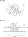
- FIGS. 26 and 27 show the second insulator 53 to which the flexible substrate 61 is attached in this manner.
- the opening portion 62A of the flexible conductor 63 is situated on the +Z direction side of the through hole 53B of the second insulator 53.
- the contact portions 54B of the three pairs of contacts 54 are exposed on the pair of inner lateral surfaces 53C of the through hole 53B of the second insulator 53.
- the first insulator 12 is first inserted between the middle parts of the three wires W1 and the surface of the garment C, and the middle parts of the three wires W1 are bent to extend along the pair of outer lateral surfaces 12B of the body portion 12A of the first insulator 12 and are separately accommodated in the corresponding wire conductor accommodation grooves 12C of the body portion 12A.
- the second insulator 53 is pressed in the -Z direction toward the first insulator 12 from the +Z direction side of the first insulator 12. As shown in FIGS. 26 and 27 , the second insulator 53 has the flexible substrate 61 attached thereto.
- the +Z directional part of the body portion 12A of the first insulator 12 passes through the through hole 53B of the second insulator 53 and the opening portion 62A of the flexible substrate 61 to protrude on the +Z direction side of the flexible substrate 61.
- step portions 53D of the second insulator 53 shown in FIG. 22 abut onto the projections 12D of the first insulator 12 shown in FIG. 3 , the position of the second insulator 53 in the Z direction with respect to the first insulator 12 is restricted, and the second insulator 53 is fitted to the first insulator 12.
- the contact portions 54B of the three pairs of contacts 54 are exposed on the pair of inner lateral surfaces 53C of the through hole 53B of the second insulator 53.
- the middle part of each wire W1 is sandwiched between the pair of outer lateral surfaces 12B of the body portion 12A of the first insulator 12 and the contact portions 54B of the pair of contacts 54 exposed on the pair of inner lateral surfaces 53C of the through hole 53B of the second insulator 53, makes contact with the contact portions 54B of the pair of contacts 54 with a predetermined contact pressure, and is electrically connected to the pair of contacts 54.
- the body portion 12A of the first insulator 12 and the middle parts of the three wires W1 that are bent to extend along the pair of outer lateral surfaces 12B of the body portion 12A are cut at a height H2 of the +Z directional surface of the flexible substrate 61 in a single step by using a nipper or another cutting tool.
- the +Z directional part of the body portion 12A of the first insulator 12 and the middle parts of the three wires W1 protruding on the +Z direction side of the flexible substrate 61 are cut and removed in this manner, and the connecting member 51 is thus assembled.
- the three wires W1 are each divided into two halves separately situated on the +X direction side and the -X direction side of the first insulator 12 to thereby form the wire conductor 21 disposed on the +X direction side of the first insulator 12 and the wire conductor 21 disposed on the -X direction side of the first insulator 12 as shown in FIG. 29 .
- three pairs of the wire conductors 21 are formed.
- the wire conductors 21 disposed on the +X direction side are electrically connected to the contact portions 54B of the contacts 54 exposed on the +X directional inner lateral surface 53C of the through hole 53B of the second insulator 53, and the wire conductors 21 disposed on the -X direction side are electrically connected to the contact portions 54B of the contacts 54 exposed on the -X directional inner lateral surface 53C of the through hole 53B of the second insulator 53.
- three pairs of the contacts 54 can be electrically connected to three pairs of the wire conductors 21 with ease.
- tip end surfaces, facing in the +Z direction, of the pair of wire conductors 21 and a tip end surface, facing in the +Z direction, of the body portion 12A of the first insulator 12 that has passed through the through hole 53B of the second insulator 53 and the opening portion 62A of the flexible substrate 61 are situated at the same height in the Z direction along the pair of outer lateral surfaces of the first insulator 12 and situated in the same plane (XY plane).
- FIG. 30 shows an assembly view of a connecting member 71 according to Embodiment 3.
- the three wires W2 are disposed on the +Z direction side of a first insulator 72
- the second insulator 53 is disposed on the +Z direction side of the three wires W2
- three pairs of contacts 54 are disposed on the +Z direction side of the second insulator 53
- the flexible substrate 61 is disposed on the +Z direction side of the three pairs of contacts 54.
- the second insulator 53, the three pairs of contacts 54, and the flexible substrate 61 are the same as those used in Embodiment 2.
- wire W1 used in Embodiment 1 is made of, for instance, a fibrous wire formed from a conductive thread woven or knitted therein
- a wire W2 used as a wire W2 is a coated wire configured such that an outer periphery of a conductor portion 81 is covered by an insulating coating portion 82 as shown in FIG. 31 .
- the conductor portion 81 may be either a so-called solid wire constituted of one conductor or a so-called stranded wire constituted of plural conductors being stranded.
- the first insulator 72 is made of, for example, an insulating resin, and includes a body portion 72A of flat plate shape extending in the +Z direction along a YZ plane.
- the body portion 72A includes a pair of outer lateral surfaces 72B separately facing in the +X direction and the -X direction, and three wire conductor accommodation grooves 72C are formed in the pair of outer lateral surfaces 72B, the wire conductor accommodation grooves 72C being aligned in the Y direction with predetermined intervals therebetween and each extending along the Z direction.
- the wire conductor accommodation grooves 72C accommodate the conductor portions 81 of the wires W2 when the connecting member 71 is assembled and each have a groove width corresponding to the diameter of the conductor portion 81 and a groove depth smaller than the diameter of the conductor portion 81.
- the body portion 72A is provided, at opposite end surfaces in the Y direction and at the -Z directional end, separately with projections 72D projecting in the Y direction.
- the insulating coating portion 82 is partly removed to thereby have the conductor portion 81 exposed at a middle part of each wire W2 as shown in FIG. 31 .
- the first insulator 72 is inserted between the conductor portions 81 exposed at middle parts of the three wires W2 and the surface of the garment C, and the conductor portions 81 of the three wires W2 are bent to extend along the pair of outer lateral surfaces 72B of the body portion 72A of the first insulator 72 and are separately accommodated in the corresponding wire conductor accommodation grooves 72C of the body portion 72A.
- the flexible substrate 61 is attached to the second insulator 53 as shown in FIGS. 26 and 27 .
- the second insulator 53 is pressed in the -Z direction toward the first insulator 72 from the +Z direction side of the first insulator 72.
- the +Z directional part of the body portion 72A of the first insulator 72 passes through the through hole 53B of the second insulator 53 and the opening portion 62A of the flexible substrate 61 to protrude on the +Z direction side of the flexible substrate 61.
- step portions 53D of the second insulator 53 shown in FIG. 22 abut onto the projections 72D of the first insulator 72 shown in FIG. 32 , the position of the second insulator 53 in the Z direction with respect to the first insulator 72 is restricted, and the second insulator 53 is fitted to the first insulator 72.
- the contact portions 54B of the three pairs of contacts 54 are exposed on the pair of inner lateral surfaces 53C of the through hole 53B of the second insulator 53.
- the conductor portion 81 exposed at the middle part of each wire W2 and accommodated in the corresponding wire conductor accommodation groove 72C of the body portion 72A of the first insulator 72 is sandwiched between the pair of outer lateral surfaces 72B of the body portion 72A of the first insulator 72 and the contact portions 54B of the pair of contacts 54 exposed on the pair of inner lateral surfaces 53C of the through hole 53B of the second insulator 53, makes contact with the contact portions 54B of the pair of contacts 54 with a predetermined contact pressure, and is electrically connected to the pair of contacts 54.
- the body portion 72A of the first insulator 72 and the conductor portions 81 at the middle parts of the three wires W2 that are bent to extend along the pair of outer lateral surfaces 72B of the body portion 72A are cut at the height H2 of the +Z directional surface of the flexible substrate 61 in a single step by using a nipper or another cutting tool.
- the +Z directional part of the body portion 72A of the first insulator 72 and the conductor portions 81 at the middle parts of the three wires W2 protruding on the +Z direction side of the flexible substrate 61 are cut and removed in this manner, and the connecting member 71 is thus assembled.
- the three wires W2 are each divided into two halves separately situated on the +X direction side and the -X direction side of the first insulator 72 to thereby form a wire conductor 83 disposed on the +X direction side of the first insulator 72 and a wire conductor 83 disposed on the -X direction side of the first insulator 72 as shown in FIG. 34 .
- three pairs of the wire conductors 83 are formed.
- the wire conductors 83 disposed on the +X direction side are electrically connected to the contact portions 54B of the contacts 54 exposed on the +X directional inner lateral surface 53C of the through hole 53B of the second insulator 53, and the wire conductors 83 disposed on the -X direction side are electrically connected to the contact portions 54B of the contacts 54 exposed on the -X directional inner lateral surface 53C of the through hole 53B of the second insulator 53.
- tip end surfaces, facing in the +Z direction, of the pair of wire conductors 83 and a tip end surface, facing in the +Z direction, of the body portion 72A of the first insulator 72 that has passed through the through hole 53B of the second insulator 53 and the opening portion 62A of the flexible substrate 61 are situated at the same height in the Z direction along the pair of outer lateral surfaces of the first insulator 72 and situated in the same plane (XY plane).
- the tip end surfaces of the body portion 72A of the first insulator 72 and the wire conductors 83 are situated in substantially the same plane and at close heights in the Z direction along the pair of outer lateral surfaces of the first insulator 72, since the body portion 72A and the wires W2 are cut by the same cutting tool in a single step.
- the flexible substrate 61 is attached to the second insulator 53 in Embodiments 2 and 3 described above, the flexible substrate 61 is not folded into, for example, the through hole 53B of the second insulator 53, and hence it is possible to attach, in place of the flexible substrate 61, a non-flexible, so-called rigid substrate to the second insulator 53.
- the connecting member 11, 51, 71 is mounted on the garment C serving as the mounting object
- the mounting object is not limited to the garment C; for instance, the connecting member 11, 51, 71 can be mounted on a seat, a bed, or a bedding piece in or on which the user lies, a bag or the like that the user carries or wears, or other goods with or to which the user's body directly or indirectly makes contact or is closely situated.
Landscapes
- Engineering & Computer Science (AREA)
- Manufacturing & Machinery (AREA)
- Textile Engineering (AREA)
- Microelectronics & Electronic Packaging (AREA)
- Coupling Device And Connection With Printed Circuit (AREA)
- Connections By Means Of Piercing Elements, Nuts, Or Screws (AREA)
- Multi-Conductor Connections (AREA)
Abstract
Description
- The present invention relates to a connecting method and a connecting member, in particular, to a connecting method and a connecting member for electrically connecting a wire conductor disposed along a surface of a mounting object to a connecting conductor.
- The present invention also relates to a wiring member including a wire conductor and a connecting member, and a garment on which the wiring member is mounted.
- As a connector connected to a flexible conductor, for instance,
JP 2005-122901 A FIG. 35 . The connector 1 is mounted on a flexibleflat cable 2 and includes a connectingconductor 4 made of a metal plate having apiercing piece 3, and a metal receivinggroove plate 6 provided with a receivinggroove 5. - When the
piercing piece 3 of the connectingconductor 4 pierces theflat cable 2 while the connectingconductor 4 and the receivinggroove plate 6 are aligned such that thepiercing piece 3 is inserted along one end of thereceiving groove 5, awire conductor 7 disposed inside theflat cable 2 is sheared by thepiercing piece 3. With insertion of thepiercing piece 3, a sheared part of thewire conductor 7 is caught in a gap formed between the other end of the receivinggroove 5 and thepiercing piece 3 to constitute a stretchedcut part 7A contacting thepiercing piece 3. As a result, the connectingconductor 4 and thewire conductor 7 are electrically connected to each other. - As shown in
FIG. 35 , with thepiercing piece 3 piercing theflat cable 2, thewire conductor 7 is sheared and divided into two conductor parts separately disposed on opposite sides of thepiercing piece 3. Meanwhile, of the two conductor parts thus divided, only one conductor part having thestretched cut part 7A is electrically connected to the connectingconductor 4 to form an electric circuit, whereas the other conductor part that does not include thestretched cut part 7A does not contribute to the electric circuit and thus becomes a useless part. - Accordingly, for connecting a plurality of connecting
conductors 4 to a plurality ofwire conductors 7, it is necessary to dispose connectingconductors 4 andwire conductors 7 on a one-to-one basis, and thus there is a problem in that a lot of work is required to form an electric circuit with multiple systems. - The present invention has been made to overcome the conventional problem as above and aims at providing a connecting method and a connecting member capable of electrically connecting a plurality of connecting conductors to a plurality of wire conductors with ease.
- The present invention also aims at providing a wiring member including a wire conductor and a connecting member, and a garment on which the wire conductor is mounted.
- A connecting method according to the present invention is one for electrically connecting a pair of wire conductors disposed along a surface of a mounting object to a pair of connecting conductors, the connecting method comprising:
- disposing a wire along the surface of the mounting object;
- disposing a first insulator between the surface of the mounting object and a middle part of the wire, the first insulator including a pair of outer lateral surfaces separately facing in opposite directions from each other along the surface of the mounting object;
- bending the middle part of the wire to extend along the pair of outer lateral surfaces of the first insulator;
- fitting a second insulator to the first insulator such that the middle part of the wire that is bent and part of the first insulator pass through and protrude from a through hole of the second insulator, whereby the middle part of the wire is sandwiched between the pair of outer lateral surfaces of the first insulator and the pair of connecting conductors exposed on a pair of inner lateral surfaces of the through hole of the second insulator to make contact with the pair of connecting conductors; and
- cutting and removing the middle part of the wire and the part of the first insulator protruding from the through hole of the second insulator, whereby the wire is divided into two halves to form the pair of wire conductors, and the pair of wire conductors are electrically connected to the pair of connecting conductors.
- A connecting member according to the present invention is one mounted on a mounting object and electrically connecting a pair of wire conductors disposed along a surface of the mounting object to a pair of connecting conductors, the connecting member comprising:
- a first insulator disposed on the surface of the mounting object and including a pair of outer lateral surfaces separately facing in opposite directions from each other along the surface of the mounting object;
- a second insulator including a through hole through which at least part of the first insulator passes; and
- the pair of connecting conductors retained by the second insulator,
- wherein the through hole of the second insulator includes a pair of inner lateral surfaces opposing the pair of outer lateral surfaces of the first insulator,
- the pair of connecting conductors are exposed on the pair of inner lateral surfaces of the through hole,
- the pair of wire conductors are bent to extend along the pair of outer lateral surfaces of the first insulator and are sandwiched between the pair of outer lateral surfaces of the first insulator and the pair of connecting conductors exposed on the pair of inner lateral surfaces of the through hole of the second insulator to be thereby electrically connected to the pair of connecting conductors, and
- tip end surfaces of the pair of wire conductors that are bent to extend along the pair of outer lateral surfaces of the first insulator and a tip end surface of the first insulator that has passed through the through hole of the second insulator are situated at a same height or close heights to each other in a direction along the pair of outer lateral surfaces of the first insulator.
- A wiring member according to the present invention is one mounted on a mounting object, the wiring member comprising:
- at least a pair of wire conductors; and
- the connecting member.
- A garment according to the present invention serves as the mounting object on which the wiring member is mounted.
-
-
FIG. 1 is a perspective view showing a connecting member according to Embodiment 1 of the invention. -
FIG. 2 is an assembly view of the connecting member according to Embodiment 1. -
FIG. 3 is a perspective view showing a first insulator used in the connecting member of Embodiment 1. -
FIG. 4 is a perspective view of a second insulator used in the connecting member of Embodiment 1 when viewed from an obliquely upper position. -
FIG. 5 is a perspective view of the second insulator used in the connecting member of Embodiment 1 when viewed from an obliquely lower position. -
FIG. 6 is a perspective view of a flexible substrate used in the connecting member of Embodiment 1 when viewed from an obliquely upper position. -
FIG. 7 is a perspective view of the flexible substrate used in the connecting member of Embodiment 1 when viewed from an obliquely lower position. -
FIG. 8 is a perspective view showing a state where a pair of fold portions of the flexible substrate are folded into a through hole of the second insulator in the connecting member of Embodiment 1 when viewed from an obliquely upper position. -
FIG. 9 is a perspective view showing the state where the pair of fold portions of the flexible substrate are folded into the through hole of the second insulator in the connecting member of Embodiment 1 when viewed from an obliquely lower position. -
FIG. 10 is a perspective view showing a garment used in Embodiment 1. -
FIG. 11 is a perspective view showing the garment to which a plurality of wires are attached in Embodiment 1. -
FIG. 12 is a perspective view showing the first insulator disposed between a surface of the garment and middle parts of the plurality of wires in Embodiment 1. -
FIG. 13 is a cross-sectional view showing the first insulator disposed between the surface of the garment and the middle parts of the plurality of wires in Embodiment 1. -
FIG. 14 is a perspective view showing a state where the second insulator is fitted to the first insulator in Embodiment 1. -
FIG. 15 is a cross-sectional view showing the state where the second insulator is fitted to the first insulator in Embodiment 1. -
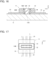
FIG. 16 is a cross-sectional view showing the connecting member of Embodiment 1. -
FIG. 17 is a plan view showing the connecting member of Embodiment 1. -
FIG. 18 is a perspective view showing the garment on which the connecting member according to Embodiment 1 is mounted. -
FIG. 19 is a perspective view showing a wiring member in which a plurality of wire conductors are connected to the connecting member of Embodiment 1. -
FIG. 20 is an assembly view of a connecting member according to Embodiment 2. -
FIG. 21 is a perspective view of a second insulator used in the connecting member according toEmbodiment 2 when viewed from an obliquely upper position. -
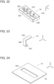
FIG. 22 is a perspective view of the second insulator used in the connecting member according toEmbodiment 2 when viewed from an obliquely lower position. -
FIG. 23 is a perspective view showing a contact used in the connecting member of Embodiment 2. -
FIG. 24 is a perspective view of a flexible substrate used in the connecting member ofEmbodiment 2 when viewed from an obliquely upper position. -
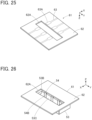
FIG. 25 is a perspective view of the flexible substrate used in the connecting member ofEmbodiment 2 when viewed from an obliquely lower position. -
FIG. 26 is a perspective view of a state where the contacts and the flexible substrate are attached to the second insulator in the connecting member ofEmbodiment 2 when viewed from an obliquely upper position. -
FIG. 27 is a perspective view of the state where the contacts and the flexible substrate are attached to the second insulator in the connecting member ofEmbodiment 2 when viewed from an obliquely lower position. -
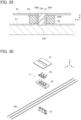
FIG. 28 is a cross-sectional view showing a state where the second insulator is fitted to the first insulator inEmbodiment 2. -
FIG. 29 is a cross-sectional view showing the connecting member of Embodiment 2. -
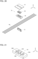
FIG. 30 is an assembly view of a connecting member according to Embodiment 3. -
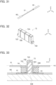
FIG. 31 is an enlarged partial perspective view showing a wire used in the connecting member of Embodiment 3. -
FIG. 32 is a perspective view showing a first insulator used in the connecting member of Embodiment 3. -
FIG. 33 is a cross-sectional view showing a state where the second insulator is fitted to the first insulator inEmbodiment 3. -
FIG. 34 is a cross-sectional view showing the connecting member ofEmbodiment 3. -
FIG. 35 is a cross-sectional view showing a conventional connector mounted on a flat cable. - Embodiments of the present invention are described below based on the accompanying drawings.
-
FIG. 1 shows a connectingmember 11 according to Embodiment 1. The connectingmember 11 is to be mounted on a mounting object constituted of, for example, a garment and is used to electrically connect pairs ofwire conductors 21 disposed along a surface of the mounting object to pairs of connecting conductors. - The connecting
member 11 includes afirst insulator 12, asecond insulator 13 fitted to thefirst insulator 12, and aflexible substrate 31 retained by thefirst insulator 12 and thesecond insulator 13. Thesecond insulator 13 is fitted to thefirst insulator 12 while being disposed on theflexible substrate 31. - The
flexible substrate 31 includes pairs of connecting conductors, and the pairs ofwire conductors 21 are electrically connected to the pairs of connecting conductors of theflexible substrate 31 between thefirst insulator 12 and thesecond insulator 13. - For convenience, the
flexible substrate 31 is defined as extending along an XY plane, the direction in which the pairs ofwire conductors 21 extend toward the connectingmember 11 is referred to as "X direction," and the direction perpendicular to an XY plane is referred to as "Z direction." Thesecond insulator 13 is disposed on the +Z directional surface of theflexible substrate 31. - In
FIG. 1 , three pairs ofwire conductors 21 are shown as the pairs ofwire conductors 21, and the three pairs ofwire conductors 21 are connected to three pairs of connecting conductors of theflexible substrate 31. -
FIG. 2 shows an assembly view of the connectingmember 11. Three wires W1 are disposed on the +Z direction side of thefirst insulator 12. The three wires W1 are aligned in the Y direction with predetermined intervals therebetween and each extend in the X direction. As the wire W1, use can be made of, for instance, a fibrous wire formed from a conductive thread woven or knitted therein. - The
flexible substrate 31 is disposed on the +Z direction side of the three wires W1, and thesecond insulator 13 is disposed further on the +Z direction side of theflexible substrate 31. - As shown in
FIG. 3 , thefirst insulator 12 is made of, for example, an insulating resin, and includes abody portion 12A of flat plate shape extending in the +Z direction along a YZ plane. Thebody portion 12A includes a pair of outerlateral surfaces 12B separately facing in the +X direction and the -X direction, and three wireconductor accommodation grooves 12C are formed in the pair of outer lateral surfaces 12B, the wireconductor accommodation grooves 12C being aligned in the Y direction with predetermined intervals therebetween and each extending along the Z direction. The wireconductor accommodation grooves 12C accommodate the wires W1 when the connectingmember 11 is assembled and each have a groove width corresponding to the width of the wire W1 and a groove depth smaller than the thickness dimension of the wire W1. - The
body portion 12A has a thickness D1 in the X direction. - In addition, the
body portion 12A is provided, at opposite end surfaces in the Y direction and at the -Z directional end, separately withprojections 12D projecting in the Y direction. - As shown in
FIG. 4 , thesecond insulator 13 is made of, for example, an insulating resin, and includes abody portion 13A of flat plate shape extending along an XY plane. Thebody portion 13A is provided with a throughhole 13B penetrating thebody portion 13A in the Z direction and extending in the Y direction. The throughhole 13B includes a pair of innerlateral surfaces 13C opposing each other in the X direction and each extending along a YZ plane, and has a width D2 in the X direction. The width D2 in the X direction of the throughhole 13B has a slightly larger dimension than the thickness D1 in the X direction of thebody portion 12A of thesecond insulator 12 such that the +Z directional part of thebody portion 12A can pass through the throughhole 13B in the Z direction. - As shown in
FIG. 5 , thebody portion 13A is also provided withstep portions 13D each facing in the -Z direction and separately formed at opposite ends in the Y direction of the throughhole 13B. - As shown in
FIG. 6 , theflexible substrate 31 includes a flexible insulatingbase 32 of sheet shape, and the insulatingbase 32 is provided with a H-shapedopening portion 32A extending long in the Y direction. Theopening portion 32A is formed of a cut penetrating the insulatingbase 32 in the Z direction and has a size corresponding to the throughhole 13B of thesecond insulator 13. Owing to theopening portion 32A, a pair offold portions 32B are formed to oppose each other in the X direction and each extend in the Y direction. The pair offold portions 32B are to be folded into the throughhole 13B of thesecond insulator 13 when the connectingmember 11 is assembled. - As shown in
FIG. 7 , the insulatingbase 32 is provided on its back surface facing in the -Z direction with three pairs offlexible conductors 33 each extending in the X direction so as to form a linear pattern. Twoflexible conductors 33 constituting each pair are separately disposed on the +X direction side and the -X direction side of theopening portion 32A across theopening portion 32A and are both situated on a single straight line extending in the X direction. Theflexible conductors 33 separately extend to reach the pair offold portions 32B, and three pairs of connectingconductors 34 formed of theflexible conductors 33 are separately disposed on the back surfaces facing in the -Z direction of thefold portions 32B. - As shown in
FIG. 6 , also on the front surface facing in the +Z direction of the insulatingbase 32, three pairs offlexible conductors 33 are formed near the +X directional end and the -X directional end of the insulatingbase 32. The three pairs offlexible conductors 33 formed on the front surface of the insulatingbase 32 are each electrically connected to the correspondingflexible conductor 33 on the back surface of the insulatingbase 32 through an interior of the insulatingbase 32. - When the connecting
member 11 is assembled, thebody portion 12A of thefirst insulator 12 is inserted in the throughhole 13B of thesecond insulator 13 from the -Z direction with theflexible substrate 31 intervening therebetween. In this process, as shown inFIGS. 8 and 9 , the pair offold portions 32B of theflexible substrate 31 are pressed by thebody portion 12A of thefirst insulator 12 to be thereby positioned on the pair of innerlateral surfaces 13C of the throughhole 13B of thesecond insulator 13. As a result, the three pairs of connectingconductors 34 disposed on the back surfaces of the pair offold portions 32B are exposed on the pair of innerlateral surfaces 13C of the throughhole 13B of thesecond insulator 13. - Next, described is a connecting method for connecting the three pairs of
wire conductors 21 to the three pairs of connectingconductors 34 by mounting the connectingmember 11 according to Embodiment 1 on a garment C serving as a mounting object. - As shown in
FIG. 10 , first, the garment C on whose surface six electrodes E are disposed is prepared. The six electrodes E constitute three pairs of electrodes E, each pair of which consists of two electrodes E disposed on the same position in the Y direction. - Next, as shown in
FIG. 11 , opposite ends of three wires W1 are separately connected to the three pairs of electrodes E of the garment C. The three wires W1 correspond to the three pairs of electrodes E, and opposite ends of each wire W1 are connected to the corresponding pair of electrodes E by, for example, soldering. At this time, a middle part of each wire W1 is not fixed to the garment C and is thus movable, and middle parts of the three wires W1 are disposed to be close to one another. - In addition, as shown in
FIG. 12 , thefirst insulator 12 is inserted between the middle parts of the three wires W1 that are not fixed to the garment C and the surface of the garment C, and the middle parts of the three wires W1 are bent to extend along the pair of outer lateral surfaces 12B of thefirst insulator 12 and are separately accommodated in the corresponding wireconductor accommodation grooves 12C of thebody portion 12A. - The wire
conductor accommodation groove 12C has a smaller depth than the thickness dimension of the wire W1, and therefore, as shown inFIG. 13 , the surface of the wire W1 accommodated in the wireconductor accommodation groove 12C protrudes to the outside in the X direction from the pair of outer lateral surfaces 12B of thebody portion 12A. - In this state, the
flexible substrate 31 is disposed on the +Z direction side of thefirst insulator 12, and, in addition, thesecond insulator 13 is pressed in the -Z direction toward thefirst insulator 12 from the +Z direction side of theflexible substrate 31. - Hence, the pair of
fold portions 32B of theflexible substrate 31 are folded into the throughhole 13B of thesecond insulator 13 by thebody portion 12A of thefirst insulator 12 as shown inFIGS. 8 and 9 , and the +Z directional part of thebody portion 12A of thefirst insulator 12 passes through theopening portion 32A of theflexible substrate 31 and the throughhole 13B of thesecond insulator 13 to project on the +Z direction side of thesecond insulator 13 as shown inFIG. 14 . - Since the
step portions 13D of thesecond insulator 13 shown inFIG. 5 abut onto theprojections 12D of thefirst insulator 12 shown inFIG. 3 , the position of thesecond insulator 13 in the Z direction with respect to thefirst insulator 12 is restricted, and thesecond insulator 13 is fitted to thefirst insulator 12. - At this time, as shown in
FIGS. 8 and 9 , the three pairs of connectingconductors 34 disposed on the back surfaces of the pair offold portions 32B of theflexible substrate 31 are exposed on the pair of innerlateral surfaces 13C of the throughhole 13B of thesecond insulator 13, and as shown inFIG. 13 , the surface of each wire W1 accommodated in the wireconductor accommodation groove 12C of thefirst insulator 12 protrudes to the outside in the X direction from the pair of outer lateral surfaces 12B of thebody portion 12A. - With this constitution, as shown in
FIG. 15 , the middle part of each wire W1 is sandwiched between the pair of outer lateral surfaces 12B of thebody portion 12A of thefirst insulator 12 and the pair of connectingconductors 34 exposed on the pair of innerlateral surfaces 13C of the throughhole 13B of thesecond insulator 13, makes contact with the pair of connectingconductors 34 with a predetermined contact pressure, and is electrically connected to the pair of connectingconductors 34. - In this state, the
body portion 12A of thefirst insulator 12 and the middle parts of the three wires W1 that are bent to extend along the pair of outer lateral surfaces 12B of thebody portion 12A are cut at a height H1 of the +Z directional surface of thesecond insulator 13. This process of cutting thebody portion 12A and the three wires W1 can be carried out by a single step using, for example, a nipper or another cutting tool. - The +Z directional part of the
body portion 12A of thefirst insulator 12 and the middle parts of the three wires W1 protruding on the +Z direction side of thesecond insulator 13 are cut and removed in this manner, and the connectingmember 11 shown inFIG. 1 is thus assembled. - Since the middle parts of the three wires W1 bent to extend along the pair of outer lateral surfaces 12B of the
body portion 12A of thefirst insulator 12 and protruding on the +Z direction side of thesecond insulator 13 are cut and removed, the three wires W1 are each divided into two halves separately situated on the +X direction side and the -X direction side of thefirst insulator 12 to thereby form thewire conductor 21 disposed on the +X direction side of thefirst insulator 12 and thewire conductor 21 disposed on the -X direction side of thefirst insulator 12 as shown inFIG. 16 . In other words, three pairs of thewire conductors 21 are formed. - The
wire conductor 21 disposed on the +X direction side is electrically connected to the connectingconductor 34 exposed on the +X directional innerlateral surface 13C of the throughhole 13B of thesecond insulator 13, while thewire conductor 21 disposed on the -X direction side is electrically connected to the connectingconductor 34 exposed on the -X directional innerlateral surface 13C of the throughhole 13B of thesecond insulator 13. - By using the three wires W1 to assemble the connecting
member 11 as described above, the three pairs of connectingconductors 34 can be electrically connected to the three pairs ofwire conductors 21 with ease. - Since part of the
body portion 12A of thefirst insulator 12 and middle parts of the three wires W1 protruding on the +Z direction side of thesecond insulator 13 are cut and removed, as shown inFIG. 1 , tip end surfaces, facing in the +Z direction, of the pair ofwire conductors 21 that are bent to extend along the pair of outer lateral surfaces 12B of thefirst insulator 12 and a tip end surface, facing in the +Z direction, of thebody portion 12A of thefirst insulator 12 that has passed through the throughhole 13B of thesecond insulator 13 are situated at the same height in the Z direction along the pair of outer lateral surfaces of thefirst insulator 12 and situated in the same plane (XY plane). - Even if a minute step is generated between the tip end surfaces, facing in the +Z direction, of the pair of
wire conductors 21 and the tip end surface, facing in the +Z direction, of thebody portion 12A of thefirst insulator 12 due to, for example, an edge shape of a cutting tool or elasticity difference between respective materials of thefirst insulator 12 and thewire conductors 21, the tip end surfaces of thebody portion 12A of thefirst insulator 12 and thewire conductors 21 are situated in substantially the same plane and at close heights in the Z direction along the pair of outer lateral surfaces of thefirst insulator 12, since thebody portion 12A and the wires W1 are cut by the same cutting tool in a single step. - In addition, since the three pairs of
wire conductors 21 are formed as a result of cutting and removing middle parts of the three wires W1, as shown inFIG. 17 , a pair ofwire conductors 21 corresponding to each wire W1 extend on a single straight line L on both sides of thefirst insulator 12 in the X direction. -
FIG. 18 shows the garment C on which the connectingmember 11 according to Embodiment 1 is mounted. Three pairs of thewire conductors 21 drawn from the connectingmember 11 are separately connected to corresponding electrodes E. - Then, a circuit module (not shown) such as a measuring circuit or a wireless transmitting circuit is connected to the three pairs of the
wire conductors 21 via theflexible substrate 31 disposed in the connectingmember 11, whereby the user's biological data including the heart rate and the body temperature obtained using the electrodes E of the garment C can be transmitted to the circuit module, and the circuit module can perform various measurements or wirelessly transmit the biological data to a remote measurement device. - In Embodiment 1 described above, the connecting
member 11 is assembled with the three wires W1 whose opposite end portions are separately connected to the electrodes E of the garment C as shown inFIG. 11 ; similarly, the connectingmember 11 can be assembled with three wires W1 whose opposite end portions are not connected to the electrodes E of the garment C by using thefirst insulator 12, thesecond insulator 13, and theflexible substrate 31. - A
wiring member 41 in which the three pairs ofwire conductors 21 are thus connected to the connectingmember 11 is shown inFIG. 19 . With use of thewiring member 41, it is possible to easily prepare the garment C which can obtain biological data by simply connecting end portions of the three pairs of thewire conductors 21 of thewiring member 41 to six electrodes E disposed on a surface of the garment C as shown inFIG. 10 . - In the connecting
member 11 according to Embodiment 1 described above, since three wires W 1 are used, three pairs ofwire conductors 21 are connected to three pairs of connectingconductors 34, but this is not the sole case. For instance, a connecting member can be configured such that with use of a single wire W1, a pair ofwire conductors 21 are connected to a pair of connectingconductors 34, that two pairs ofwire conductors 21 are connected to two pairs of connectingconductors 34, and even that four or more pairs ofwire conductors 21 are connected to four or more pairs of connectingconductors 34. -
FIG. 20 shows an assembly view of a connectingmember 51 according toEmbodiment 2. The three wires W1 are disposed on the +Z direction side of thefirst insulator 12, asecond insulator 53 is disposed on the +Z direction side of the three wires W 1, three pairs ofcontacts 54 are disposed on the +Z direction side of thesecond insulator 53, and aflexible substrate 61 is disposed on the +Z direction side of the three pairs ofcontacts 54. - Two
contacts 54 opposing each other in the X direction constitute each pair, and the three pairs ofcontacts 54 are aligned in the Y direction. In the connectingmember 51, thesecond insulator 53 is fitted to thefirst insulator 12, the three pairs ofcontacts 54 are retained by thesecond insulator 53, and theflexible substrate 61 is retained by the three pairs ofcontacts 54. - The three wires W1 and the
first insulator 12 are the same as those used in Embodiment 1. - As shown in
FIG. 21 , thesecond insulator 53 is made of, for example, an insulating resin, and includes abody portion 53A of flat plate shape extending along an XY plane. Thebody portion 53A is provided with a throughhole 53B penetrating thebody portion 53A in the Z direction and extending in the Y direction. The throughhole 53B includes a pair of innerlateral surfaces 53C opposing each other in the X direction and each extending along a YZ plane. - As shown in
FIG. 22 , thebody portion 53A is also provided withstep portions 53D each facing in the -Z direction and separately formed at opposite ends in the Y direction of the throughhole 53B. - In addition, as shown in
FIGS. 21 and22 , three pairs ofcontact accommodation grooves 53E are formed to extend from the +Z directional surface of thebody portion 53A to the -Z directional surface of thebody portion 53A across the inner lateral surfaces 53C. The three pairs ofcontact accommodation grooves 53E consist of threecontact accommodation grooves 53E aligned in the Y direction with predetermined intervals therebetween on the +X direction side of the throughhole 53B and threecontact accommodation grooves 53E aligned in the Y direction with predetermined intervals therebetween on the -X direction side of the throughhole 53B. -
FIG. 23 shows the configuration of onecontact 54 of those aligned on the -X direction side among the three pairs ofcontacts 54 aligned in the Y direction. Thecontact 54 is formed of a bent band-shaped member made of a metal component, and includes a connectingportion 54A extending in the X direction along an XY plane, acontact portion 54B extending from the +X directional end of the connectingportion 54A in the -Z direction along a YZ plane, and abent portion 54C extending from the -Z directional end of thecontact portion 54B in the -X direction along an XY plane. - Note that, of the three pairs of
contacts 54, thecontacts 54 aligned on the +X direction side have the same configuration as that of thecontact 54 shown inFIG. 23 but are disposed in the opposite orientation therefrom in the X direction. - Each
contact 54 is retained by thesecond insulator 53 while being accommodated in the correspondingcontact accommodation groove 53E of thebody portion 53A of thesecond insulator 53 and constitutes a connecting conductor in the connectingmember 51 ofEmbodiment 2. - The
second insulator 53 retaining the three pairs ofcontacts 54 as above can be produced by, for example, insert molding. - As shown in
FIGS. 24 and25 , theflexible substrate 61 includes a flexible insulatingbase 62 of sheet shape, and the insulatingbase 62 is provided with a rectangular-shapedopening portion 62A extending long in the Y direction. Theopening portion 62A corresponds to the throughhole 53B of thesecond insulator 53. - The insulating
base 62 is provided on its back surface facing in the -Z direction with three pairs offlexible conductors 63 each extending linearly in the X direction. Twoflexible conductors 63 constituting each pair are separately disposed on the +X direction side and the -X direction side of theopening portion 62A across theopening portion 62A and each include a rectangular connectingpad 63A formed in the vicinity of theopening portion 62A. - When the connecting
member 51 is assembled, theflexible substrate 61 is disposed on the +Z direction side of thesecond insulator 53 retaining the three pairs ofcontacts 54, and the connectingpads 63A of the three pairs offlexible conductors 63 of theflexible substrate 61 are each connected with the connectingportion 54A of thecorresponding contact 54 by, for example, soldering. -
FIGS. 26 and27 show thesecond insulator 53 to which theflexible substrate 61 is attached in this manner. Theopening portion 62A of theflexible conductor 63 is situated on the +Z direction side of the throughhole 53B of thesecond insulator 53. When the three pairs ofcontacts 54 are retained by thesecond insulator 53, thecontact portions 54B of the three pairs ofcontacts 54 are exposed on the pair of innerlateral surfaces 53C of the throughhole 53B of thesecond insulator 53. - For mounting the connecting
member 51 according toEmbodiment 2 on the garment C serving as a mounting object, similarly to Embodiment 1, as shown inFIGS. 12 and 13 , thefirst insulator 12 is first inserted between the middle parts of the three wires W1 and the surface of the garment C, and the middle parts of the three wires W1 are bent to extend along the pair of outer lateral surfaces 12B of thebody portion 12A of thefirst insulator 12 and are separately accommodated in the corresponding wireconductor accommodation grooves 12C of thebody portion 12A. - In this state, the
second insulator 53 is pressed in the -Z direction toward thefirst insulator 12 from the +Z direction side of thefirst insulator 12. As shown inFIGS. 26 and27 , thesecond insulator 53 has theflexible substrate 61 attached thereto. - With this constitution, as shown in
FIG. 28 , the +Z directional part of thebody portion 12A of thefirst insulator 12 passes through the throughhole 53B of thesecond insulator 53 and theopening portion 62A of theflexible substrate 61 to protrude on the +Z direction side of theflexible substrate 61. - Since the
step portions 53D of thesecond insulator 53 shown inFIG. 22 abut onto theprojections 12D of thefirst insulator 12 shown inFIG. 3 , the position of thesecond insulator 53 in the Z direction with respect to thefirst insulator 12 is restricted, and thesecond insulator 53 is fitted to thefirst insulator 12. - At this time, the
contact portions 54B of the three pairs ofcontacts 54 are exposed on the pair of innerlateral surfaces 53C of the throughhole 53B of thesecond insulator 53. With this constitution, the middle part of each wire W1 is sandwiched between the pair of outer lateral surfaces 12B of thebody portion 12A of thefirst insulator 12 and thecontact portions 54B of the pair ofcontacts 54 exposed on the pair of innerlateral surfaces 53C of the throughhole 53B of thesecond insulator 53, makes contact with thecontact portions 54B of the pair ofcontacts 54 with a predetermined contact pressure, and is electrically connected to the pair ofcontacts 54. - In this state, the
body portion 12A of thefirst insulator 12 and the middle parts of the three wires W1 that are bent to extend along the pair of outer lateral surfaces 12B of thebody portion 12A are cut at a height H2 of the +Z directional surface of theflexible substrate 61 in a single step by using a nipper or another cutting tool. - The +Z directional part of the
body portion 12A of thefirst insulator 12 and the middle parts of the three wires W1 protruding on the +Z direction side of theflexible substrate 61 are cut and removed in this manner, and the connectingmember 51 is thus assembled. - Since the middle parts of the three wires W1 bent to extend along the pair of outer lateral surfaces 12B of the
body portion 12A of thefirst insulator 12 and protruding on the +Z direction side of theflexible substrate 61 are cut and removed, the three wires W1 are each divided into two halves separately situated on the +X direction side and the -X direction side of thefirst insulator 12 to thereby form thewire conductor 21 disposed on the +X direction side of thefirst insulator 12 and thewire conductor 21 disposed on the -X direction side of thefirst insulator 12 as shown inFIG. 29 . In other words, three pairs of thewire conductors 21 are formed. - The
wire conductors 21 disposed on the +X direction side are electrically connected to thecontact portions 54B of thecontacts 54 exposed on the +X directional innerlateral surface 53C of the throughhole 53B of thesecond insulator 53, and thewire conductors 21 disposed on the -X direction side are electrically connected to thecontact portions 54B of thecontacts 54 exposed on the -X directional innerlateral surface 53C of the throughhole 53B of thesecond insulator 53. - By using the three wires W1 to assemble the connecting
member 51 as described above, three pairs of thecontacts 54 can be electrically connected to three pairs of thewire conductors 21 with ease. - Since the +Z directional part of the
body portion 12A of thefirst insulator 12 and middle parts of the three wires W1 protruding on the +Z direction side of theflexible substrate 61 are cut and removed, as shown inFIG. 29 , tip end surfaces, facing in the +Z direction, of the pair ofwire conductors 21 and a tip end surface, facing in the +Z direction, of thebody portion 12A of thefirst insulator 12 that has passed through the throughhole 53B of thesecond insulator 53 and theopening portion 62A of theflexible substrate 61 are situated at the same height in the Z direction along the pair of outer lateral surfaces of thefirst insulator 12 and situated in the same plane (XY plane). - Even if a minute step is generated between the tip end surfaces, facing in the +Z direction, of the pair of
wire conductors 21 and the tip end surface, facing in the +Z direction, of thebody portion 12A of thefirst insulator 12 due to, for example, an edge shape of a cutting tool or elasticity difference between respective materials of thefirst insulator 12 and thewire conductors 21, the tip end surfaces of thebody portion 12A of thefirst insulator 12 and thewire conductors 21 are situated in substantially the same plane and at close heights in the Z direction along the pair of outer lateral surfaces of thefirst insulator 12, since thebody portion 12A and the wires W1 are cut by the same cutting tool in a single step. -
FIG. 30 shows an assembly view of a connectingmember 71 according toEmbodiment 3. The three wires W2 are disposed on the +Z direction side of afirst insulator 72, thesecond insulator 53 is disposed on the +Z direction side of the three wires W2, three pairs ofcontacts 54 are disposed on the +Z direction side of thesecond insulator 53, and theflexible substrate 61 is disposed on the +Z direction side of the three pairs ofcontacts 54. - The
second insulator 53, the three pairs ofcontacts 54, and theflexible substrate 61 are the same as those used inEmbodiment 2. - While the wire W1 used in Embodiment 1 is made of, for instance, a fibrous wire formed from a conductive thread woven or knitted therein, in
Embodiment 3, used as a wire W2 is a coated wire configured such that an outer periphery of aconductor portion 81 is covered by an insulatingcoating portion 82 as shown inFIG. 31 . Theconductor portion 81 may be either a so-called solid wire constituted of one conductor or a so-called stranded wire constituted of plural conductors being stranded. - As shown in
FIG. 32 , thefirst insulator 72 is made of, for example, an insulating resin, and includes abody portion 72A of flat plate shape extending in the +Z direction along a YZ plane. Thebody portion 72A includes a pair of outerlateral surfaces 72B separately facing in the +X direction and the -X direction, and three wireconductor accommodation grooves 72C are formed in the pair of outer lateral surfaces 72B, the wireconductor accommodation grooves 72C being aligned in the Y direction with predetermined intervals therebetween and each extending along the Z direction. The wireconductor accommodation grooves 72C accommodate theconductor portions 81 of the wires W2 when the connectingmember 71 is assembled and each have a groove width corresponding to the diameter of theconductor portion 81 and a groove depth smaller than the diameter of theconductor portion 81. - In addition, the
body portion 72A is provided, at opposite end surfaces in the Y direction and at the -Z directional end, separately withprojections 72D projecting in the Y direction. - For mounting the connecting
member 71 according toEmbodiment 3 on the garment C serving as a mounting object, first, the insulatingcoating portion 82 is partly removed to thereby have theconductor portion 81 exposed at a middle part of each wire W2 as shown inFIG. 31 . - Subsequently, the
first insulator 72 is inserted between theconductor portions 81 exposed at middle parts of the three wires W2 and the surface of the garment C, and theconductor portions 81 of the three wires W2 are bent to extend along the pair of outer lateral surfaces 72B of thebody portion 72A of thefirst insulator 72 and are separately accommodated in the corresponding wireconductor accommodation grooves 72C of thebody portion 72A. - Similarly to
Embodiment 2, theflexible substrate 61 is attached to thesecond insulator 53 as shown inFIGS. 26 and27 . - In this state, the
second insulator 53 is pressed in the -Z direction toward thefirst insulator 72 from the +Z direction side of thefirst insulator 72. - With this constitution, as shown in
FIG. 33 , the +Z directional part of thebody portion 72A of thefirst insulator 72 passes through the throughhole 53B of thesecond insulator 53 and theopening portion 62A of theflexible substrate 61 to protrude on the +Z direction side of theflexible substrate 61. - Since the
step portions 53D of thesecond insulator 53 shown inFIG. 22 abut onto theprojections 72D of thefirst insulator 72 shown inFIG. 32 , the position of thesecond insulator 53 in the Z direction with respect to thefirst insulator 72 is restricted, and thesecond insulator 53 is fitted to thefirst insulator 72. - At this time, the
contact portions 54B of the three pairs ofcontacts 54 are exposed on the pair of innerlateral surfaces 53C of the throughhole 53B of thesecond insulator 53. With this constitution, theconductor portion 81 exposed at the middle part of each wire W2 and accommodated in the corresponding wireconductor accommodation groove 72C of thebody portion 72A of thefirst insulator 72 is sandwiched between the pair of outer lateral surfaces 72B of thebody portion 72A of thefirst insulator 72 and thecontact portions 54B of the pair ofcontacts 54 exposed on the pair of innerlateral surfaces 53C of the throughhole 53B of thesecond insulator 53, makes contact with thecontact portions 54B of the pair ofcontacts 54 with a predetermined contact pressure, and is electrically connected to the pair ofcontacts 54. - In this state, the
body portion 72A of thefirst insulator 72 and theconductor portions 81 at the middle parts of the three wires W2 that are bent to extend along the pair of outer lateral surfaces 72B of thebody portion 72A are cut at the height H2 of the +Z directional surface of theflexible substrate 61 in a single step by using a nipper or another cutting tool. - The +Z directional part of the
body portion 72A of thefirst insulator 72 and theconductor portions 81 at the middle parts of the three wires W2 protruding on the +Z direction side of theflexible substrate 61 are cut and removed in this manner, and the connectingmember 71 is thus assembled. - Since the
conductor portions 81 at the middle parts of the three wires W2 bent to extend along the pair of outer lateral surfaces 72B of thebody portion 72A of thefirst insulator 72 and protruding on the +Z direction side of theflexible substrate 61 are cut and removed, the three wires W2 are each divided into two halves separately situated on the +X direction side and the -X direction side of thefirst insulator 72 to thereby form awire conductor 83 disposed on the +X direction side of thefirst insulator 72 and awire conductor 83 disposed on the -X direction side of thefirst insulator 72 as shown inFIG. 34 . In other words, three pairs of thewire conductors 83 are formed. - The
wire conductors 83 disposed on the +X direction side are electrically connected to thecontact portions 54B of thecontacts 54 exposed on the +X directional innerlateral surface 53C of the throughhole 53B of thesecond insulator 53, and thewire conductors 83 disposed on the -X direction side are electrically connected to thecontact portions 54B of thecontacts 54 exposed on the -X directional innerlateral surface 53C of the throughhole 53B of thesecond insulator 53. - By using the three wires W2 to assemble the connecting
member 71 as described above, three pairs of thecontacts 54 can be electrically connected to three pairs of thewire conductors 83 with ease. - Since the +Z directional part of the
body portion 72A of thefirst insulator 72 and middle parts of the three wires W2 protruding on the +Z direction side of theflexible substrate 61 are cut and removed, as shown inFIG. 34 , tip end surfaces, facing in the +Z direction, of the pair ofwire conductors 83 and a tip end surface, facing in the +Z direction, of thebody portion 72A of thefirst insulator 72 that has passed through the throughhole 53B of thesecond insulator 53 and theopening portion 62A of theflexible substrate 61 are situated at the same height in the Z direction along the pair of outer lateral surfaces of thefirst insulator 72 and situated in the same plane (XY plane). - Even if a minute step is generated between the tip end surfaces, facing in the +Z direction, of the pair of
wire conductors 83 and the tip end surface, facing in the +Z direction, of thebody portion 72A of thefirst insulator 72 due to, for example, an edge shape of a cutting tool or elasticity difference between respective materials of thefirst insulator 72 and thewire conductors 83, the tip end surfaces of thebody portion 72A of thefirst insulator 72 and thewire conductors 83 are situated in substantially the same plane and at close heights in the Z direction along the pair of outer lateral surfaces of thefirst insulator 72, since thebody portion 72A and the wires W2 are cut by the same cutting tool in a single step. - While the
flexible substrate 61 is attached to thesecond insulator 53 inEmbodiments flexible substrate 61 is not folded into, for example, the throughhole 53B of thesecond insulator 53, and hence it is possible to attach, in place of theflexible substrate 61, a non-flexible, so-called rigid substrate to thesecond insulator 53. - In addition, while in Embodiments 1 to 3 described above, the connecting
member member
Claims (12)
- A connecting method for electrically connecting a pair of wire conductors (21, 83) disposed along a surface of a mounting object (C) to a pair of connecting conductors (34, 54), the connecting method comprising:disposing a wire (W 1, W2) along the surface of the mounting object;disposing a first insulator (12, 72) between the surface of the mounting object and a middle part of the wire, the first insulator including a pair of outer lateral surfaces (12B, 72B) separately facing in opposite directions from each other along the surface of the mounting object;bending the middle part of the wire to extend along the pair of outer lateral surfaces of the first insulator;fitting a second insulator (13, 53) to the first insulator such that the middle part of the wire that is bent and part of the first insulator pass through and protrude from a through hole (13B, 53B) of the second insulator, whereby the middle part of the wire is sandwiched between the pair of outer lateral surfaces of the first insulator and the pair of connecting conductors (34, 54) exposed on a pair of inner lateral surfaces (13C, 53C) of the through hole of the second insulator to make contact with the pair of connecting conductors; andcutting and removing the middle part of the wire and the part of the first insulator protruding from the through hole of the second insulator, whereby the wire is divided into two halves to form the pair of wire conductors (21, 83), and the pair of wire conductors are electrically connected to the pair of connecting conductors (34, 54).
- A connecting member (11, 51, 71) mounted on a mounting object (C) and electrically connecting a pair of wire conductors (21, 83) disposed along a surface of the mounting object to a pair of connecting conductors (34, 54), the connecting member comprising:a first insulator (12, 72) disposed on the surface of the mounting object and including a pair of outer lateral surfaces (12B, 72B) separately facing in opposite directions from each other along the surface of the mounting object;a second insulator (13, 53) including a through hole (13B, 53B) through which at least part of the first insulator passes; andthe pair of connecting conductors (34, 54) retained by the second insulator,wherein the through hole of the second insulator includes a pair of inner lateral surfaces (13C, 53C) opposing the pair of outer lateral surfaces of the first insulator,the pair of connecting conductors are exposed on the pair of inner lateral surfaces of the through hole,the pair of wire conductors are bent to extend along the pair of outer lateral surfaces of the first insulator and are sandwiched between the pair of outer lateral surfaces of the first insulator and the pair of connecting conductors exposed on the pair of inner lateral surfaces of the through hole of the second insulator to be thereby electrically connected to the pair of connecting conductors, andtip end surfaces of the pair of wire conductors (21, 83) that are bent to extend along the pair of outer lateral surfaces of the first insulator and a tip end surface of the first insulator (12, 72) that has passed through the through hole of the second insulator are situated at a same height or close heights to each other in a direction along the pair of outer lateral surfaces of the first insulator.
- The connecting member (11) according to claim 2,wherein the pair of connecting conductors (34) are formed of a pair of flexible conductors (33) exposed on a surface of a flexible substrate (31) that extends along a surface of the mounting object, andpart of the flexible substrate is bent to extend along the pair of inner lateral surfaces of the through hole, and the pair of flexible conductors on the flexible substrate that are bent are electrically connected to the pair of wire conductors (21) on opposite sides of the first insulator (12).
- The connecting member (51, 71) according to claim 2,wherein the pair of connecting conductors are formed of a pair of contacts (54) each made of a metal component, andthe pair of contacts are disposed such that parts thereof extend along the pair of inner lateral surfaces of the through hole, and the pair of contacts are electrically connected to the pair of wire conductors (21, 83) on opposite sides of the first insulator (12, 72).
- The connecting member (51, 71) according to claim 4, comprising a flexible substrate (61) having a pair of flexible conductors (63) exposed on a surface thereof,
wherein the pair of contacts (54) are soldered to the pair of flexible conductors of the flexible substrate. - The connecting member (11, 51, 71) according to one of claims 2-5, wherein the first insulator (12, 72) includes a pair of wire conductor accommodation grooves (12C, 72C) formed in the pair of outer lateral surfaces to accommodate the pair of wire conductors.
- The connecting member (11, 51, 71) according to one of claims 2-6, wherein the pair of wire conductors (21, 83) extend on a single straight line on both sides of the first insulator.
- The connecting member (11, 51, 71) according to one of claims 2-7, comprising a plurality of pairs of the connecting conductors (34, 54) retained by the second insulator and exposed on the pair of inner lateral surfaces of the through hole,
wherein a plurality of pairs of the wire conductors (21, 83) are bent to extend along the pair of outer lateral surfaces (12B, 72B) of the first insulator (12, 72) and sandwiched between the pair of outer lateral surfaces of the first insulator and the plurality of pairs of the connecting conductors exposed on the pair of inner lateral surfaces (13C, 53C) of the through hole (13B, 53B) of the second insulator (13, 53) to be thereby electrically connected to the plurality of pairs of the connecting conductors. - A wiring member (41) mounted on a mounting object (C), the wiring member comprising:at least a pair of wire conductors (21, 83); andthe connecting member (11, 51, 71) according to one of claims 2-8.
- The wiring member (41) according to claim 9, wherein the at least a pair of wire conductors (21, 83) are formed of wires using conductive fibers, or of electric wires.
- A garment (C) serving as the mounting object on which the wiring member (41) according to claim 9 or 10 is mounted.
- The garment (C) according to claim 11, on which at least a pair of electrodes (E) are disposed,
wherein the at least a pair of wire conductors are connected to the at least a pair of electrodes.
Applications Claiming Priority (1)
| Application Number | Priority Date | Filing Date | Title |
|---|---|---|---|
| JP2023064787A JP2024151457A (en) | 2023-04-12 | 2023-04-12 | Connection method, connection member, wiring member and clothing |
Publications (2)
| Publication Number | Publication Date |
|---|---|
| EP4447231A1 true EP4447231A1 (en) | 2024-10-16 |
| EP4447231B1 EP4447231B1 (en) | 2025-12-10 |
Family
ID=89666484
Family Applications (1)
| Application Number | Title | Priority Date | Filing Date |
|---|---|---|---|
| EP24153403.1A Active EP4447231B1 (en) | 2023-04-12 | 2024-01-23 | Connecting method, wiring member, and garment |
Country Status (4)
| Country | Link |
|---|---|
| US (1) | US20240347994A1 (en) |
| EP (1) | EP4447231B1 (en) |
| JP (1) | JP2024151457A (en) |
| CN (1) | CN118801130A (en) |
Citations (5)
| Publication number | Priority date | Publication date | Assignee | Title |
|---|---|---|---|---|
| JP2005122901A (en) | 2003-09-08 | 2005-05-12 | Furukawa Electric Co Ltd:The | Connector for flat circuit body and connection structure between the connector and flat circuit body |
| US20190027842A1 (en) * | 2017-07-24 | 2019-01-24 | Japan Aviation Electronics Industry, Limited | Connection assisting member and circuit board assembly |
| US20210075135A1 (en) * | 2019-09-09 | 2021-03-11 | Japan Aviation Electronics Industry, Limited | Connector and connecting method |
| US20210075146A1 (en) * | 2019-09-09 | 2021-03-11 | Japan Aviation Electronics Industry, Limited | Connector |
| US20210098898A1 (en) * | 2019-09-26 | 2021-04-01 | Japan Aviation Electronics Industry, Limited | Connector and connecting method |
Family Cites Families (11)
| Publication number | Priority date | Publication date | Assignee | Title |
|---|---|---|---|---|
| US4808112A (en) * | 1986-09-25 | 1989-02-28 | Tektronix, Inc. | High density connector design using anisotropically pressure-sensitive electroconductive composite sheets |
| US5326272A (en) * | 1990-01-30 | 1994-07-05 | Medtronic, Inc. | Low profile electrode connector |
| US6394833B1 (en) * | 2001-04-25 | 2002-05-28 | Miraco, Inc. | Flat flexible cable connector |
| US6695629B1 (en) * | 2002-10-25 | 2004-02-24 | Hewlett-Packard Development Company, L.P. | Low-profile mounting and connecting scheme for circuit boards |
| US20060280322A1 (en) * | 2005-05-19 | 2006-12-14 | Abe Kaho | Discreet interface system |
| WO2007084552A2 (en) * | 2006-01-17 | 2007-07-26 | Lifesync Corporation | Multi-lead keyhold connector |
| US11258189B2 (en) * | 2019-10-03 | 2022-02-22 | Japan Aviation Electronics Industry, Limited | Connector and connecting method |
| JP7438085B2 (en) * | 2020-11-18 | 2024-02-26 | 日本航空電子工業株式会社 | connector |
| JP7558095B2 (en) * | 2021-03-19 | 2024-09-30 | 日本航空電子工業株式会社 | Connectors and connection methods |
| JP7807994B2 (en) * | 2022-06-27 | 2026-01-28 | 日本航空電子工業株式会社 | Sheet-shaped conductive member and connector |
| JP7854383B2 (en) * | 2022-11-24 | 2026-05-01 | 日本航空電子工業株式会社 | Connector assembly |
-
2023
- 2023-04-12 JP JP2023064787A patent/JP2024151457A/en active Pending
-
2024
- 2024-01-23 EP EP24153403.1A patent/EP4447231B1/en active Active
- 2024-02-15 US US18/442,545 patent/US20240347994A1/en active Pending
- 2024-03-01 CN CN202410238559.1A patent/CN118801130A/en active Pending
Patent Citations (5)
| Publication number | Priority date | Publication date | Assignee | Title |
|---|---|---|---|---|
| JP2005122901A (en) | 2003-09-08 | 2005-05-12 | Furukawa Electric Co Ltd:The | Connector for flat circuit body and connection structure between the connector and flat circuit body |
| US20190027842A1 (en) * | 2017-07-24 | 2019-01-24 | Japan Aviation Electronics Industry, Limited | Connection assisting member and circuit board assembly |
| US20210075135A1 (en) * | 2019-09-09 | 2021-03-11 | Japan Aviation Electronics Industry, Limited | Connector and connecting method |
| US20210075146A1 (en) * | 2019-09-09 | 2021-03-11 | Japan Aviation Electronics Industry, Limited | Connector |
| US20210098898A1 (en) * | 2019-09-26 | 2021-04-01 | Japan Aviation Electronics Industry, Limited | Connector and connecting method |
Also Published As
| Publication number | Publication date |
|---|---|
| JP2024151457A (en) | 2024-10-25 |
| US20240347994A1 (en) | 2024-10-17 |
| EP4447231B1 (en) | 2025-12-10 |
| CN118801130A (en) | 2024-10-18 |
Similar Documents
| Publication | Publication Date | Title |
|---|---|---|
| EP3376601B1 (en) | Connector | |
| EP3783742B1 (en) | Connector and connecting method | |
| US11165179B2 (en) | Connector and connecting method | |
| EP4346017B1 (en) | Connector | |
| US12424774B2 (en) | Connector | |
| EP3799217B1 (en) | Connector and connecting method | |
| US12506313B2 (en) | Sheet type conductive member and connector | |
| CN117438812A (en) | Sheet conductive parts, connectors, clothing and connector installation methods | |
| JP4084292B2 (en) | Pressure welding structure of coaxial cable | |
| EP4447231B1 (en) | Connecting method, wiring member, and garment | |
| US12230907B2 (en) | Electrical connector for connecting an electric wire to a flat flexible conductor and an electrical connector assembly therefor | |
| CN117438147A (en) | Conductive parts and manufacturing methods thereof, connectors and installation methods thereof, clothing | |
| EP4611180A1 (en) | Connector | |
| EP4507128A1 (en) | Connector and connector assembly | |
| US10862254B2 (en) | Coated conductive wire connecting method, coated conductive wire connecting structure and coated conductive wire connecting member | |
| US20240283172A1 (en) | Connector and connector assembly | |
| EP4311033B1 (en) | Sheet type conductive member, connector, garment, and connector mounting method | |
| EP4343974B1 (en) | Connector | |
| EP4333216A1 (en) | Connector |
Legal Events
| Date | Code | Title | Description |
|---|---|---|---|
| PUAI | Public reference made under article 153(3) epc to a published international application that has entered the european phase |
Free format text: ORIGINAL CODE: 0009012 |
|
| STAA | Information on the status of an ep patent application or granted ep patent |
Free format text: STATUS: REQUEST FOR EXAMINATION WAS MADE |
|
| 17P | Request for examination filed |
Effective date: 20240123 |
|
| AK | Designated contracting states |
Kind code of ref document: A1 Designated state(s): AL AT BE BG CH CY CZ DE DK EE ES FI FR GB GR HR HU IE IS IT LI LT LU LV MC ME MK MT NL NO PL PT RO RS SE SI SK SM TR |
|
| RBV | Designated contracting states (corrected) |
Designated state(s): AL AT BE BG CH CY CZ DE DK EE ES FI FR GB GR HR HU IE IS IT LI LT LU LV MC ME MK MT NL NO PL PT RO RS SE SI SK SM TR |
|
| STAA | Information on the status of an ep patent application or granted ep patent |
Free format text: STATUS: EXAMINATION IS IN PROGRESS |
|
| 17Q | First examination report despatched |
Effective date: 20250129 |
|
| GRAP | Despatch of communication of intention to grant a patent |
Free format text: ORIGINAL CODE: EPIDOSNIGR1 |
|
| STAA | Information on the status of an ep patent application or granted ep patent |
Free format text: STATUS: GRANT OF PATENT IS INTENDED |
|
| GRAS | Grant fee paid |
Free format text: ORIGINAL CODE: EPIDOSNIGR3 |
|
| GRAA | (expected) grant |
Free format text: ORIGINAL CODE: 0009210 |
|
| STAA | Information on the status of an ep patent application or granted ep patent |
Free format text: STATUS: THE PATENT HAS BEEN GRANTED |
|
| INTG | Intention to grant announced |
Effective date: 20251021 |
|
| AK | Designated contracting states |
Kind code of ref document: B1 Designated state(s): AL AT BE BG CH CY CZ DE DK EE ES FI FR GB GR HR HU IE IS IT LI LT LU LV MC ME MK MT NL NO PL PT RO RS SE SI SK SM TR |
|
| REG | Reference to a national code |
Ref country code: CH Ref legal event code: F10 Free format text: ST27 STATUS EVENT CODE: U-0-0-F10-F00 (AS PROVIDED BY THE NATIONAL OFFICE) Effective date: 20251210 Ref country code: GB Ref legal event code: FG4D |
|
| REG | Reference to a national code |
Ref country code: DE Ref legal event code: R096 Ref document number: 602024001544 Country of ref document: DE |
|
| REG | Reference to a national code |
Ref country code: IE Ref legal event code: FG4D |
|
| PG25 | Lapsed in a contracting state [announced via postgrant information from national office to epo] |
Ref country code: ES Free format text: LAPSE BECAUSE OF FAILURE TO SUBMIT A TRANSLATION OF THE DESCRIPTION OR TO PAY THE FEE WITHIN THE PRESCRIBED TIME-LIMIT Effective date: 20251210 |
|
| REG | Reference to a national code |
Ref country code: LT Ref legal event code: MG9D |
|
| PG25 | Lapsed in a contracting state [announced via postgrant information from national office to epo] |
Ref country code: NO Free format text: LAPSE BECAUSE OF FAILURE TO SUBMIT A TRANSLATION OF THE DESCRIPTION OR TO PAY THE FEE WITHIN THE PRESCRIBED TIME-LIMIT Effective date: 20260310 |
|
| PGFP | Annual fee paid to national office [announced via postgrant information from national office to epo] |
Ref country code: DE Payment date: 20251217 Year of fee payment: 3 |
|
| PG25 | Lapsed in a contracting state [announced via postgrant information from national office to epo] |
Ref country code: HR Free format text: LAPSE BECAUSE OF FAILURE TO SUBMIT A TRANSLATION OF THE DESCRIPTION OR TO PAY THE FEE WITHIN THE PRESCRIBED TIME-LIMIT Effective date: 20251210 Ref country code: FI Free format text: LAPSE BECAUSE OF FAILURE TO SUBMIT A TRANSLATION OF THE DESCRIPTION OR TO PAY THE FEE WITHIN THE PRESCRIBED TIME-LIMIT Effective date: 20251210 |
|
| PGFP | Annual fee paid to national office [announced via postgrant information from national office to epo] |
Ref country code: AT Payment date: 20260301 Year of fee payment: 3 |
|
| REG | Reference to a national code |
Ref country code: NL Ref legal event code: MP Effective date: 20251210 |
|
| PG25 | Lapsed in a contracting state [announced via postgrant information from national office to epo] |
Ref country code: RS Free format text: LAPSE BECAUSE OF FAILURE TO SUBMIT A TRANSLATION OF THE DESCRIPTION OR TO PAY THE FEE WITHIN THE PRESCRIBED TIME-LIMIT Effective date: 20260310 |
|
| PGFP | Annual fee paid to national office [announced via postgrant information from national office to epo] |
Ref country code: FR Payment date: 20260204 Year of fee payment: 3 |
|
| PG25 | Lapsed in a contracting state [announced via postgrant information from national office to epo] |
Ref country code: LV Free format text: LAPSE BECAUSE OF FAILURE TO SUBMIT A TRANSLATION OF THE DESCRIPTION OR TO PAY THE FEE WITHIN THE PRESCRIBED TIME-LIMIT Effective date: 20251210 |
|
| PG25 | Lapsed in a contracting state [announced via postgrant information from national office to epo] |
Ref country code: BG Free format text: LAPSE BECAUSE OF FAILURE TO SUBMIT A TRANSLATION OF THE DESCRIPTION OR TO PAY THE FEE WITHIN THE PRESCRIBED TIME-LIMIT Effective date: 20251210 |