EP4447220A1 - End cap assembly, battery cell, battery, and electric device - Google Patents
End cap assembly, battery cell, battery, and electric device Download PDFInfo
- Publication number
- EP4447220A1 EP4447220A1 EP22949977.7A EP22949977A EP4447220A1 EP 4447220 A1 EP4447220 A1 EP 4447220A1 EP 22949977 A EP22949977 A EP 22949977A EP 4447220 A1 EP4447220 A1 EP 4447220A1
- Authority
- EP
- European Patent Office
- Prior art keywords
- blocking
- plate
- injection hole
- cap
- liquid injection
- Prior art date
- Legal status (The legal status is an assumption and is not a legal conclusion. Google has not performed a legal analysis and makes no representation as to the accuracy of the status listed.)
- Pending
Links
Images


Classifications
-
- H—ELECTRICITY
- H01—ELECTRIC ELEMENTS
- H01M—PROCESSES OR MEANS, e.g. BATTERIES, FOR THE DIRECT CONVERSION OF CHEMICAL ENERGY INTO ELECTRICAL ENERGY
- H01M10/00—Secondary cells; Manufacture thereof
- H01M10/05—Accumulators with non-aqueous electrolyte
- H01M10/052—Li-accumulators
- H01M10/0525—Rocking-chair batteries, i.e. batteries with lithium insertion or intercalation in both electrodes; Lithium-ion batteries
-
- H—ELECTRICITY
- H01—ELECTRIC ELEMENTS
- H01M—PROCESSES OR MEANS, e.g. BATTERIES, FOR THE DIRECT CONVERSION OF CHEMICAL ENERGY INTO ELECTRICAL ENERGY
- H01M50/00—Constructional details or processes of manufacture of the non-active parts of electrochemical cells other than fuel cells, e.g. hybrid cells
- H01M50/60—Arrangements or processes for filling or topping-up with liquids; Arrangements or processes for draining liquids from casings
- H01M50/609—Arrangements or processes for filling with liquid, e.g. electrolytes
- H01M50/627—Filling ports
- H01M50/636—Closing or sealing filling ports, e.g. using lids
-
- H—ELECTRICITY
- H01—ELECTRIC ELEMENTS
- H01M—PROCESSES OR MEANS, e.g. BATTERIES, FOR THE DIRECT CONVERSION OF CHEMICAL ENERGY INTO ELECTRICAL ENERGY
- H01M50/00—Constructional details or processes of manufacture of the non-active parts of electrochemical cells other than fuel cells, e.g. hybrid cells
- H01M50/10—Primary casings; Jackets or wrappings
- H01M50/147—Lids or covers
- H01M50/148—Lids or covers characterised by their shape
- H01M50/15—Lids or covers characterised by their shape for prismatic or rectangular cells
-
- H—ELECTRICITY
- H01—ELECTRIC ELEMENTS
- H01M—PROCESSES OR MEANS, e.g. BATTERIES, FOR THE DIRECT CONVERSION OF CHEMICAL ENERGY INTO ELECTRICAL ENERGY
- H01M50/00—Constructional details or processes of manufacture of the non-active parts of electrochemical cells other than fuel cells, e.g. hybrid cells
- H01M50/30—Arrangements for facilitating escape of gases
- H01M50/375—Vent means sensitive to or responsive to temperature
-
- H—ELECTRICITY
- H01—ELECTRIC ELEMENTS
- H01M—PROCESSES OR MEANS, e.g. BATTERIES, FOR THE DIRECT CONVERSION OF CHEMICAL ENERGY INTO ELECTRICAL ENERGY
- H01M50/00—Constructional details or processes of manufacture of the non-active parts of electrochemical cells other than fuel cells, e.g. hybrid cells
- H01M50/30—Arrangements for facilitating escape of gases
- H01M50/392—Arrangements for facilitating escape of gases with means for neutralising or absorbing electrolyte; with means for preventing leakage of electrolyte through vent holes
-
- H—ELECTRICITY
- H01—ELECTRIC ELEMENTS
- H01M—PROCESSES OR MEANS, e.g. BATTERIES, FOR THE DIRECT CONVERSION OF CHEMICAL ENERGY INTO ELECTRICAL ENERGY
- H01M50/00—Constructional details or processes of manufacture of the non-active parts of electrochemical cells other than fuel cells, e.g. hybrid cells
- H01M50/60—Arrangements or processes for filling or topping-up with liquids; Arrangements or processes for draining liquids from casings
- H01M50/609—Arrangements or processes for filling with liquid, e.g. electrolytes
- H01M50/627—Filling ports
- H01M50/636—Closing or sealing filling ports, e.g. using lids
- H01M50/645—Plugs
- H01M50/655—Plugs specially adapted for venting
-
- H—ELECTRICITY
- H01—ELECTRIC ELEMENTS
- H01M—PROCESSES OR MEANS, e.g. BATTERIES, FOR THE DIRECT CONVERSION OF CHEMICAL ENERGY INTO ELECTRICAL ENERGY
- H01M50/00—Constructional details or processes of manufacture of the non-active parts of electrochemical cells other than fuel cells, e.g. hybrid cells
- H01M50/60—Arrangements or processes for filling or topping-up with liquids; Arrangements or processes for draining liquids from casings
- H01M50/668—Means for preventing spilling of liquid or electrolyte, e.g. when the battery is tilted or turned over
-
- H—ELECTRICITY
- H01—ELECTRIC ELEMENTS
- H01M—PROCESSES OR MEANS, e.g. BATTERIES, FOR THE DIRECT CONVERSION OF CHEMICAL ENERGY INTO ELECTRICAL ENERGY
- H01M50/00—Constructional details or processes of manufacture of the non-active parts of electrochemical cells other than fuel cells, e.g. hybrid cells
- H01M50/10—Primary casings; Jackets or wrappings
- H01M50/147—Lids or covers
- H01M50/155—Lids or covers characterised by the material
- H01M50/157—Inorganic material
- H01M50/159—Metals
-
- Y—GENERAL TAGGING OF NEW TECHNOLOGICAL DEVELOPMENTS; GENERAL TAGGING OF CROSS-SECTIONAL TECHNOLOGIES SPANNING OVER SEVERAL SECTIONS OF THE IPC; TECHNICAL SUBJECTS COVERED BY FORMER USPC CROSS-REFERENCE ART COLLECTIONS [XRACs] AND DIGESTS
- Y02—TECHNOLOGIES OR APPLICATIONS FOR MITIGATION OR ADAPTATION AGAINST CLIMATE CHANGE
- Y02E—REDUCTION OF GREENHOUSE GAS [GHG] EMISSIONS, RELATED TO ENERGY GENERATION, TRANSMISSION OR DISTRIBUTION
- Y02E60/00—Enabling technologies; Technologies with a potential or indirect contribution to GHG emissions mitigation
- Y02E60/10—Energy storage using batteries
-
- Y—GENERAL TAGGING OF NEW TECHNOLOGICAL DEVELOPMENTS; GENERAL TAGGING OF CROSS-SECTIONAL TECHNOLOGIES SPANNING OVER SEVERAL SECTIONS OF THE IPC; TECHNICAL SUBJECTS COVERED BY FORMER USPC CROSS-REFERENCE ART COLLECTIONS [XRACs] AND DIGESTS
- Y02—TECHNOLOGIES OR APPLICATIONS FOR MITIGATION OR ADAPTATION AGAINST CLIMATE CHANGE
- Y02P—CLIMATE CHANGE MITIGATION TECHNOLOGIES IN THE PRODUCTION OR PROCESSING OF GOODS
- Y02P70/00—Climate change mitigation technologies in the production process for final industrial or consumer products
- Y02P70/50—Manufacturing or production processes characterised by the final manufactured product
Definitions
- the present application relates to the technical field of batteries, and particularly to a cap assembly, a battery cell, a battery and an electric-powered device.
- lithium-ion batteries As a new type of secondary battery, lithium-ion batteries have advantages of high energy density and power density, long cycle life, good safety, and environmental protection. With the development of modern society and enhancement of people's environmental awareness, more and more devices use lithium batteries as power sources, such as mobile phones, laptops, electric tools, and electric vehicles, which provide a broad space for the application and development of the lithium batteries.
- the amount of electrolyte in a battery cell is related to long-term stable operation of the battery, so it is necessary to avoid loss of the electrolyte during manufacturing and operation of the battery cell.
- the present application provides a cap assembly, a battery cell, a battery, and an electric-powered device, which can reduce loss of electrolyte and improve safety of the battery cell during operation.
- the embodiments of the present disclosure provide a cap assembly, including:
- the electrolyte can be blocked and prevented from directly flowing out through the liquid injection hole during the formation process. Moreover, when injecting the electrolyte through the liquid injection hole, the injected liquid can be prevented from directly spraying onto the electrode assembly and thus causing displacement or deformation of the electrode assembly, thereby improving safety of an electrolyte injection process. Further, by providing the blocking plate, at least part of the electrolyte can be prevented from flowing out through the liquid injection hole. Moreover, the blocking plate is provided with the vent hole, gases inside the battery cell can be discharged. The above configuration can ensure normal discharge of gases while preventing loss of the electrolyte. Further, by providing a plurality of blocking plates, multiple blocking measures are provided to prevent discharge of the electrolyte during the formation process, thereby further enhancing the effect of reducing loss of the electrolyte.
- the blocking plate includes a receiving cavity on a side facing the cap plate, and an orthographic projection of the receiving cavity on the cap plate at least partially covers the liquid injection hole.
- the blocking plate includes a side plate and a bottom plate, the side plate is disposed around an outer periphery of the liquid injection hole, the bottom plate is connected to the side plate and opposite to the liquid injection hole, and the side plate and the bottom plate enclose and form the receiving cavity in a cylindrical shape.
- the sealing nail in the liquid injection hole can be accommodated and positioned, thereby preventing the sealing nail from falling off, avoiding damage of the blocking plate caused by movements of the sealing nail during the electrolyte injection or vacuuming in the formation process, and thus improving safety of the blocking device.
- a plurality of vent holes are provided. By providing the plurality of vent holes, efficiency of gas discharge during the formation process can be increased.
- the plurality of vent holes are arranged on the blocking plate at uniform intervals.
- the above configuration can ensure uniform discharge of the gases, improve balancing of forces on the blocking plate, increase efficiency of the gas discharge, and extend service life of the blocking plate.
- diameters of the plurality of blocking plates decrease gradually in the first direction.
- a quantity Q of the blocking plates is in a range of 2 ⁇ Q ⁇ 5.
- the blocking device further includes a liquid absorbing assembly disposed in the receiving cavity, and the liquid absorbing assembly is formed as a structure with multiple holes.
- the electrolyte can be temporarily absorbed in the holes of the liquid absorbing assembly, and the electrolyte can flow back after the formation process is completed, thereby reducing loss of the electrolyte in the formation process.
- the liquid absorbing assembly includes a first liquid absorbing piece disposed between the blocking plate and the liquid injection hole, the first liquid absorbing piece is provided with a plurality of liquid absorbing holes on its surface, and the first liquid absorbing piece has a size larger than an aperture of the liquid injection hole.
- the liquid absorbing assembly includes a second liquid absorbing piece disposed between adjacent two blocking plates, the second liquid absorbing piece is provided with a plurality of liquid absorbing holes on its surface, and the second liquid absorbing piece has a size larger than the apertures of the vent holes on the adjacent two blocking plates.
- the present application further provides a battery including the battery cell of the above embodiments.
- the present application further provides an electric-powered device, including the battery of the above embodiments, and the battery is adapted to provide electrical energy.
- association relationship of associated objects indicating that there can be three types of relationships, for example, A and/or B can indicate the presence of A alone, the presence of A and B simultaneously, and the presence of B alone.
- character "/" in the present application generally indicates that the associated objects before and after the character are in an "or" relationship.
- a plurality of in the present application refers to two or more (including two).
- a battery cell may include a lithium ion secondary battery cell, a lithium ion primary battery cell, a lithium sulfur battery cell, a sodium-lithium ion battery cell, a sodium ion battery cell, a magnesium ion battery cell, or the like, and the embodiments of the present application do not limit this aspect.
- the battery cell can be in a shape of a cylinder, a flat body, a rectangular cuboid or in other shapes, and the embodiments of the present application do not limit this aspect.
- Battery cells are generally divided into three types by packaging: cylindrical battery cells, square battery cells, and soft pack battery cells. The embodiments of the present application do not limit this aspect.
- the battery mentioned in the embodiments of the present application refers to a single physical module that includes one or more battery cells to provide higher voltage and capacity.
- the battery mentioned in the present application may include battery modules, battery packs, or the like.
- the battery generally includes a casing for packaging one or more battery cells. The casing can prevent liquids or other foreign matters from affecting charging or discharging of the battery cells.
- the negative current collector can be made of copper, the negative active substance layer includes negative active substance, and the negative active substance can be carbon or silicon. In order to ensure that there is no melting in the negative tab when high current flows through it, a plurality of negative tabs are provided and stacked together.
- the separator can be made of PP (polypropylene) or PE (polyethylene), or the like. Further, the electrode assembly may be formed as a wound structure or a stacked structure, and the embodiments of the present application are not limited to this.
- SEI film solid electrolyte interface film
- film formation In order to form a complete SEI film, it is necessary to charge the battery cell with a low current after an electrolyte injection is completed, which is known as film formation.
- the process of formation will be accompanied by generation of gases. These gases will have a negative impact on the formation rate. Meanwhile, if these gases fail to be discharged timely and remain in an interior of the battery cell, they will decrease conversion efficiency of the battery cell subsequently.
- the applicant has found that in the high temperature and negative pressure environment, some of the electrolyte in the battery cell may be extracted by a negative pressure mechanism, causing loss of the electrolyte. Moreover, the boiling point of the electrolyte will vary with the level of the negative pressure, and during the formation process, some of the electrolyte may become gaseous and be extracted along with the gases generated during the formation process, causing further loss of the electrolyte.
- the embodiments of the present application provide a cap assembly provided with a blocking device.
- the blocking device is disposed on a side of a cap plate facing an electrode assembly of the battery cell and at least partially covers a liquid injection hole, the blocking device includes a vent hole, which is adapted for communicating the liquid injection hole with a space located at a side of the blocking device facing away from the cap plate.
- a plurality of blocking plates are provided and spaced apart in a first direction, and the first direction is a direction from the electrode assembly towards the cap plate.
- the electrolyte can be blocked during the formation process to prevent it from directly flowing out through the liquid injection hole. Moreover, when injecting the electrolyte through the liquid injection hole, the injected liquid can be prevented from directly spraying onto the electrode assembly and thus causing displacement or deformation of the electrode assembly, thereby improving safety of the electrolyte injection process. Further, by providing a plurality of blocking plates, multiple blocking measures are provided to prevent discharge of the electrolyte during the formation process, thereby further enhancing the effect of reducing loss of the electrolyte.
- the technical solutions described in the embodiments of the present application are applicable to the battery and the electric-powered device using the battery.
- the electric-powered device can be a vehicle, a mobile phone, a portable device, a laptop, a ship, a spacecraft, an electric toy, an electric tool, and so on.
- Fig. 1 is a structural schematic diagram of a vehicle provided in some embodiments of the present application.
- a vehicle 1 is provided with a battery 2 in its interior, and the battery 2 can be installed at a bottom, head, or rear of the vehicle 1.
- the battery 2 can be adapted for supplying electrical power to the vehicle 1, for example, the battery 2 can serve as an operating power source of the vehicle 1.
- the vehicle 1 may further include a controller 3 and a motor 4, the controller 3 is adapted to control the battery 2 to supply electrical power to the motor 4, for example, for satisfying working electrical power requirements of the vehicle 1 for starting, navigation, and travelling.
- the battery 2 can not only serve as the operating power source for the vehicle 1, but also as a driving power source for the vehicle 1, replacing or partially replacing fuel or natural gas to provide driving power for the vehicle 1.
- Fig. 2 is an explosive schematic diagram of a battery provided in some embodiments of the present application. As shown in Fig. 2 , the battery 2 includes a housing 5 and a battery cell 7, and the battery cell 7 is accommodated within the housing 5.
- the housing 5 is adapted to accommodate the battery cell 7, and the housing 5 can be formed as various structures.
- the housing 5 may include a first portion 51 and a second portion 52, the first portion 51 and the second portion 52 cover and close each other, and the first portion 51 and the second portion 52 define a receiving space 53 for accommodating the battery cell 7.
- the second portion 52 can be formed as a hollow structure with an opening at one end, the first portion 51 is formed as a plate-like structure, and the first portion 51 covers and closes a side with the opening of the second portion 52 to form the housing 5 with the receiving space 53; or, each of the first portion 51 and the second portion 52 may be formed as a hollow structure with an opening on one side, and a side with the opening of the first portion 51 is covered by a side with opening of the second portion 52 to form the housing 5 with the receiving space 53.
- the first portion 51 and the second portion 52 can be formed in various shapes, such as cylinders, and rectangles.
- a sealing element such as sealant, a sealing ring, can further be installed between the first portion 51 and the second portion 52.
- the first portion 51 covers and closes the second portion 52 on a top of the second portion 52
- the first portion 51 can also be referred to as an upper housing cover
- the second portion 52 can also be referred to as a lower housing body.
- the battery 2 there may be one battery cell 7, or may be a plurality of battery cells 7. If there are a plurality of battery cells 7, the plurality of battery cells 7 can be connected in series, in parallel, or in hybrid, where "in hybrid" means that the plurality of battery cells 7 are connected both in series and in parallel.
- the plurality of battery cells 7 can be directly connected in series, in parallel, or in hybrid, and then an integrity composed of the plurality of battery cells 7 can be received in the housing 5; certainly, it is also available that the plurality of battery cells 7 are connected in series, in parallel, or in hybrid to form battery modules 6 at first, and then a plurality of battery modules 6 are connected in series, in parallel, or in hybrid to form an integrity, which is accommodated in the housing 5.
- Fig. 3 is an explosive schematic diagram of the battery cell 7 in the battery provided in some embodiments of the present application.
- a plurality of battery modules 6 are then connected in series, in parallel, or in hybrid to form an integrity, which is accommodated in the housing.
- a plurality of battery cells 7 in the battery module 6 can be electrically connected through a busbar, to achieve parallel, series, or hybrid connection of the plurality of battery cells 7 in the battery module 6.
- the battery cell 7 in the embodiments of the present application includes an electrode unit 10, a shell 20, and a cap assembly 30.
- the shell 20 includes an opening 21, the electrode unit 10 is accommodated within the shell 20, and the cap assembly 30 is adapted for connecting with the shell 20 and covering and closing the opening 21.
- the electrode unit 10 includes at least one electrode assembly 11.
- the electrode assembly 11 includes a positive electrode plate, a negative electrode plate, and a separator.
- the electrode assembly 11 can be an electrode assembly of a wound type, an electrode assembly of a stacked type, or an electrode assembly of other types.
- the electrode assembly 11 is an electrode assembly of a wound type.
- the positive electrode plate, the negative electrode plate, and the separator are all formed as strip structures.
- the embodiments of the present application can sequentially stack the positive electrode plate, the separator and the negative electrode plate and wind them for more than two turns to form the electrode assembly 11.
- the electrode assembly 11 is an electrode assembly of a stacked type. Specifically, the electrode assembly 11 includes a plurality of positive electrode plates and a plurality of negative electrode plates, and the positive electrode plates and negative electrode plates are alternately stacked in a direction parallel to a thickness direction of the positive electrode plates and a thickness direction of the negative electrode plates.
- the electrode unit 10 includes at least one electrode assembly 11. That is to say, in the battery cell 7, there may be one or more electrode assemblies 11 accommodated within the shell 20.
- the shell 20 is formed as a hollow structure with an opening on one side.
- the cap assembly 30 covers and closes the shell 20 at the opening and forms a sealed connection with the shell 20, so as to form a containing cavity for accommodating the electrode unit 10 and the electrolyte.
- the shell 20 can be formed in various shapes, such as a cylinder, and a cuboid.
- the shape of the shell 20 can be determined depending on the specific shape of the electrode unit 10. For example, if the electrode unit 10 is formed as a cylindrical structure, a cylindrical shell may be selected; if the electrode unit 10 is formed as a cubic structure, a cubic shell may be selected.
- the cap assembly 30 also may be of various structures, such as a plate-like structure or a hollow structure with an opening on one end.
- the shell 20 is formed as a cubic
- the cap assembly 30 is formed as a plate-like structure
- the cap assembly 30 covers and closes the opening at the top of the shell 20.
- the cap assembly 30 further includes an electrode terminal 31.
- two electrode terminals 31 are provided, and are respectively defined as a positive electrode terminal and a negative electrode terminal.
- the positive electrode terminal and the negative electrode terminal are respectively adapted for electrically connecting with the positive and negative tabs of the electrode assembly 11 to output current generated by the electrode assembly 11.
- the cap assembly 30 further includes a pressure relief mechanism 32, which is adapted to release an internal pressure or temperature of the battery cell 7 when the internal pressure or temperature of the battery cell 7 reaches a predetermined value.
- the pressure relief mechanism 32 is located between the positive electrode terminal and the negative electrode terminal, and can be a component such as an explosion-proof valve, an explosion-proof disc, a gas valve, a pressure relief valve, and a safety valve.
- the shell 20 may further be formed as a hollow structure with openings on two opposite sides.
- Two cap assemblies 30 are provided, which respectively cover and close the shell 20 at the two openings and are connected to the shell 20 in a sealing manner, so as to form the containing cavity for accommodating the electrode unit 10 and the electrolyte.
- the positive electrode terminal and the negative electrode terminal may be installed on the same cap assembly 30. In other examples, the positive electrode terminal and the negative electrode terminal are installed on the two cap assemblies 30, respectively.
- Fig. 4 is a structural schematic diagram of the cap assembly 30 provided in some embodiments of the present application
- Fig. 5 is a structural schematic diagram of the cap assembly 30 provided in some other embodiments of the present application
- Fig. 6 is a structural schematic diagram of the cap assembly 30 provided in some further embodiments of the present application
- Fig. 7 is a structural schematic diagram of the cap assembly 30 provided in some further embodiments of the present application
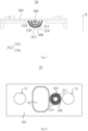
- Fig. 8 is a structural schematic diagram of the cap assembly 30 of the battery 2 in a top view in some embodiments of the present application.
- the liquid injection hole 303 is disposed on the cap plate 301, and the liquid injection hole 303 penetrates through the cap plate 301 in a thickness direction thereof and is communicated with a space in an interior of the shell 20.
- the liquid injection hole 303 is connected with a liquid injection device to inject the electrolyte into the shell 20.
- the liquid injection hole 303 is connected with the negative pressure mechanism to discharge redundant gases from the shell 20.
- the blocking device 302 is disposed inside the battery cell 7 and connected with the cap plate 301.
- the blocking device 302 may be a plate-like structure covering the liquid injection hole 303 immediately below the liquid injection hole 303, or a gap may be provided between the blocking device 302 and the liquid injection hole 303.
- the blocking device 302 may be made of plastic cement, or may be made of resin, plastic material, rubber or metal material.
- the materials for making the blocking device 302 is required to be resistant to corrosion of the electrolyte and high temperature, so as to prevent the blocking device 302 from being corroded by the electrolyte or being melted due to the high temperature during the formation process.
- the blocking device 302 below the liquid injection hole 303, the electrolyte is blocked during the formation process of the battery cell 7 to prevent it from flowing out directly through the liquid injection hole 303, and loss of the electrolyte during the formation process is effectively reduced.
- the blocking device 302 can further buffer the injection of the electrolyte, thereby preventing the injected electrolyte from directly spraying onto the electrode assembly 11 and thus causing displacement or deformation of the electrode assembly 11, and improving safety of the electrolyte injection process.
- the blocking plate 305 at least part of the electrolyte can be blocked from flowing out through the liquid injection hole 303.
- the vent hole 304 on the blocking plate 305 by providing the vent hole 304 on the blocking plate 305, the gases inside the battery cell 7 can be discharged.
- the above configuration can ensure normal discharge of gases while reducing loss of the electrolyte.
- the blocking plate 305 has a simple structure, can be conveniently manufactured, and can be applied to the liquid injection hole 303 of most structures.
- the blocking plate 305 includes a receiving cavity 306 on a side facing the cap plate 301, and an orthographic projection of the receiving cavity 306 on the cap plate 301 at least partially covers the liquid injection hole 303.
- the orthographic projection of the receiving cavity 306 on the cap plate 301 completely covers the liquid injection hole 303.
- the receiving cavity 306 is formed between the blocking plate 305 and the cap plate 301, and is communicated with the liquid injection hole 303 and the vent hole 304, respectively.
- the receiving cavity 306 can be a buffer space between the liquid injection hole 303 and the vent hole 304.
- the receiving cavity 306 By providing the receiving cavity 306, during the formation process, a portion of the refluxed electrolyte or condensed electrolyte gas can be temporarily stored and flow back into the shell 20 through the vent hole 304, thereby reducing loss of the electrolyte. Moreover, the receiving cavity 306 can accommodate the electrolyte during the electrolyte injection process, prevent the injected electrolyte from directly spraying towards the electrode assembly 11, and thus reduce the impact damage of the electrode assembly 11 caused by the electrolyte.
- the blocking plate 305 includes a side plate 307 and a bottom plate 308, the side plate 307 is disposed around an outer periphery of the liquid injection hole 303, the bottom plate 308 is connected to the side plate 307 and opposite to the liquid injection hole 303, and the side plate 307 and the bottom plate 308 enclose and form the receiving cavity 306 in a cylindrical shape.
- the sealing nail may be connected with the liquid injection hole 303 by welding or by other means. However, when the battery cell 7 moves or is subjected to external impacts, the sealing nail may fall off. The sealing nail that falls off may move during the formation process and rub with the blocking device 302, thereby causing damage of the blocking device 302. When the blocking device 302 is worn to generate a through-hole of a larger size, the sealing nail may enter the interior of the shell 20 via the through-hole and may damage the electrode assembly 11.
- the cylindrical receiving cavity 306 which is similar to the sealing nail in shape, the sealing nail can be accommodated and prevented from moving. Therefore, the cylindrical receiving cavity 306 in the present application can prevent the sealing nail from falling into the shell 20, and avoid damage of the blocking plate 305 caused by movements of the sealing nail during the electrolyte injection or vacuuming in the formation process, thereby improving safety of the blocking device 302.
- a plurality of vent holes 304 are arranged at uniform intervals on the blocking plate 305.
- the above configuration allows gases to be uniformly discharged through the blocking plate 305, can ensure a balanced force on the blocking plate 305, and meanwhile can improve efficiency of the gas discharge and extend service life of the blocking plate 305.
- the blocking device 302 includes a first blocking plate 309, a second blocking plate 310, and a third blocking plate 311 arranged sequentially in the first direction X.
- the first blocking plate 309 and the second blocking plate 310 are both formed as hemispherical structures, which occupy less space and can effectively reduce the space occupied by the blocking device 302 in the interior of the shell 20.
- the third blocking plate 311 is formed as a cylindrical structure, which can accommodate the sealing nail while blocking the electrolyte from flowing away.
- diameters of the plurality of blocking plates 305 decrease gradually in the first direction X.
- the first blocking plate 309, the second blocking plate 310, and the third blocking plate 311 can further be formed as structures with similar shapes while different sizes.
- all of the first blocking plate 309, the second blocking plate 310, and the third blocking plate 311 may be formed as cylindrical structures, or all of the first blocking plate 309, the second blocking plate 310, and the third blocking plate 311 may be formed as hemispherical or semi-ellipsoidal structures.
- the above structures may be selected based on actual usage, and there are no limitations here.
- the above configuration can divide the receiving cavity 306, and ensure a certain receiving space between adjacent two blocking plates 305, so as to improve efficiency of the gas discharge; meanwhile, it can facilitate connections of the blocking plates 305 with the cap plate 301 in a circumferential direction, thereby improving reliability of installation of the blocking device 302.
- a quantity Q of the blocking plates 305 is in a range of 2 ⁇ Q ⁇ 5. If the quantity of blocking plates 305 is less than 2, the effect of blocking the electrolyte is not significant, and some loss of electrolyte still will occur at the liquid injection hole 303. If the quantity of blocking plates is more than 5, the occupied space in the interior of the battery cell 7 is too large and the blocking plates 305 cannot be installed. Therefore, by providing a reasonable quantity for the blocking plates 305, the blocking effect can be ensured, while a weight of the cap assembly 30 can be reduced and energy density of the battery cell 7 can be ensured.
- the vent holes 304 on adjacent two blocking plates 305 are arranged in a staggered manner.
- a path of the electrolyte flowing between adjacent blocking plates 305 is extended, and a discharge velocity of the electrolyte is reduced.
- a flow path of gases generated by evaporation of the electrolyte also can be extended, thereby improving condensation efficiency of the vaporized electrolyte, and further reducing loss of the electrolyte.
- all the vent holes 304 on each of the block plate 305 have the same aperture, and in the first direction X, the apertures of the vent holes 304 on the plurality of block plates 305 decrease gradually.
- the apertures of the vent holes 304 By providing the apertures of the vent holes 304 to gradually decrease in a discharging direction of the electrolyte, the resistance to the electrolyte when the electrolyte is discharged can be gradually increased, and amount of the discharged electrolyte can be reduced.
- the liquid absorbing assembly 312 includes a first liquid absorbing piece 313 located between the blocking plate 305 and the liquid injection hole 303, the first liquid absorbing piece 313 is provided with a plurality of liquid absorbing holes on its surface, and the first liquid absorbing piece 313 has a size larger than the aperture of the liquid injection hole 303.
- the first liquid absorbing piece 313 may be made of materials resistant to corrosion of the electrolyte and high temperature, to avoid from being corroded by the electrolyte, or to prevent from being melted during the formation process.
- the first liquid absorbing piece 313 may be made of plastic cement, or may be made of resin, plastic material, rubber or metal material.
- the aluminum material can be made into the first liquid absorbing piece 313 with regular or irregular shapes, and multiple concave liquid absorbing holes may be provided on a surface of the aluminum material to absorb the electrolyte.
- the ability of the blocking device 302 to absorb the electrolyte can be increased and the effect of blocking the electrolyte from flowing away can be improved.
- the size of the first liquid absorbing piece 313 to be larger than the aperture of the liquid injection hole 303, the first liquid absorbing piece 313 can be prevented from being discharged from the liquid injection hole 303.
- the liquid absorbing assembly 312 includes a second liquid absorbing piece 314 located between adjacent two blocking plates 305, the second liquid absorbing piece 314 is provided with a plurality of liquid absorbing holes on its surface, and the second liquid absorbing piece 314 has a size larger than the apertures of the vent holes 304 on the adjacent two blocking plates 305.
- the second liquid absorbing assembly 314 is required to be made of materials resistant to corrosion of the electrolyte and high temperature, to avoid from being corroded by the electrolyte, or to prevent from being melted during the formation process.
- the second liquid absorbing piece 314 may be made of plastic cement, or may be made of resin, plastic material, rubber or metal material.
- the aluminum material can be made into the second liquid absorbing piece 314 with regular or irregular shapes, and multiple concave liquid absorbing holes may be provided on a surface of the aluminum material to absorb the electrolyte.
- the ability of the blocking device 302 to absorb the electrolyte can be increased and the effect of blocking the electrolyte from flowing away can be improved.
- the size of the second liquid absorbing piece 314 to be larger than the apertures of the vents 304, the second liquid absorbing piece 314 can be prevented from falling off through the vent holes 304, thereby preventing the second liquid absorbing piece 314 from damaging the electrode assembly 11.
- the embodiments of the present application further provide a battery 2, and referring to Figs. 2 and 4 , the battery 2 includes: the battery cell 7 in any of the above embodiments.
- the embodiments of the present application further provide an electric-powered device, which includes the battery 2 in any of the above embodiments, and the battery 2 is adapted to provide electrical energy.
- both the battery 2 and the electric-powered device as mentioned above are provided with the cap assembly 30 in the present application, they can achieve the following technical effects:
- the electrolyte can be blocked and prevented from directly flowing out through the liquid injection hole 303 during the formation process.
- the injected liquid is prevented from directly spraying onto the electrode assembly 11 and thus causing displacement or deformation of the electrode assembly 11, thereby improving safety of the liquid injection process.
Landscapes
- Chemical & Material Sciences (AREA)
- Chemical Kinetics & Catalysis (AREA)
- Electrochemistry (AREA)
- General Chemical & Material Sciences (AREA)
- Engineering & Computer Science (AREA)
- Materials Engineering (AREA)
- Manufacturing & Machinery (AREA)
- Gas Exhaust Devices For Batteries (AREA)
- Filling, Topping-Up Batteries (AREA)
Abstract
Description
- The present application claims priority of the
Chinese patent application 202221731363.9, titled "CAP ASSEMBLY, BATTERY CELL, BATTERY AND ELECTRIC-POWERED DEVICE" and filed on July 7, 2022 - The present application relates to the technical field of batteries, and particularly to a cap assembly, a battery cell, a battery and an electric-powered device.
- As a new type of secondary battery, lithium-ion batteries have advantages of high energy density and power density, long cycle life, good safety, and environmental protection. With the development of modern society and enhancement of people's environmental awareness, more and more devices use lithium batteries as power sources, such as mobile phones, laptops, electric tools, and electric vehicles, which provide a broad space for the application and development of the lithium batteries.
- Currently, safety of batteries is receiving increasing attention. The amount of electrolyte in a battery cell is related to long-term stable operation of the battery, so it is necessary to avoid loss of the electrolyte during manufacturing and operation of the battery cell.
- In view of the above issues, the present application provides a cap assembly, a battery cell, a battery, and an electric-powered device, which can reduce loss of electrolyte and improve safety of the battery cell during operation.
- On a first aspect, the embodiments of the present disclosure provide a cap assembly, including:
- a cap plate, including a liquid injection hole;
- a blocking device, disposed on a side of the cap plate facing an electrode assembly of a battery cell and at least partially covering the liquid injection hole, the blocking device including a vent hole, the vent hole being adapted for communicating the liquid injection hole with a space located at a side of the blocking device facing away from the cap plate, the blocking device including a blocking plate, the blocking plate being connected with the cap plate, and the blocking plate being provided with the vent hole which penetrates through the blocking plate, wherein a plurality of blocking plates are provided, the plurality of blocking plates are spaced apart in a first direction, and the first direction is a direction from the electrode assembly towards the cap plate.
- In the technical solutions of the embodiments of the present application, by providing the blocking device below the liquid injection hole, the electrolyte can be blocked and prevented from directly flowing out through the liquid injection hole during the formation process. Moreover, when injecting the electrolyte through the liquid injection hole, the injected liquid can be prevented from directly spraying onto the electrode assembly and thus causing displacement or deformation of the electrode assembly, thereby improving safety of an electrolyte injection process. Further, by providing the blocking plate, at least part of the electrolyte can be prevented from flowing out through the liquid injection hole. Moreover, the blocking plate is provided with the vent hole, gases inside the battery cell can be discharged. The above configuration can ensure normal discharge of gases while preventing loss of the electrolyte. Further, by providing a plurality of blocking plates, multiple blocking measures are provided to prevent discharge of the electrolyte during the formation process, thereby further enhancing the effect of reducing loss of the electrolyte.
- In some embodiments, the blocking plate includes a receiving cavity on a side facing the cap plate, and an orthographic projection of the receiving cavity on the cap plate at least partially covers the liquid injection hole. By providing the receiving cavity, a buffer space can be formed when injecting the electrolyte through the liquid injection hole for accommodating the electrolyte, thereby preventing the liquid from directly spraying towards the electrode assembly, and reducing impact of the electrolyte on the electrode assembly.
- In some embodiments, the blocking plate includes a side plate and a bottom plate, the side plate is disposed around an outer periphery of the liquid injection hole, the bottom plate is connected to the side plate and opposite to the liquid injection hole, and the side plate and the bottom plate enclose and form the receiving cavity in a cylindrical shape. By providing the cylindrical receiving cavity, the sealing nail in the liquid injection hole can be accommodated and positioned, thereby preventing the sealing nail from falling off, avoiding damage of the blocking plate caused by movements of the sealing nail during the electrolyte injection or vacuuming in the formation process, and thus improving safety of the blocking device.
- In some embodiments, a plurality of vent holes are provided. By providing the plurality of vent holes, efficiency of gas discharge during the formation process can be increased.
- In some embodiments, the plurality of vent holes are arranged on the blocking plate at uniform intervals. The above configuration can ensure uniform discharge of the gases, improve balancing of forces on the blocking plate, increase efficiency of the gas discharge, and extend service life of the blocking plate.
- In some embodiments, diameters of the plurality of blocking plates decrease gradually in the first direction. By providing the blocking plates with different diameters, the efficiency of gas discharge can be improved while facilitating connection between the blocking plate and the cap plate.
- In some embodiments, a quantity Q of the blocking plates is in a range of 2≤Q≤5. By providing a reasonable quantity of blocking plates, the blocking effect can be ensured, while a weight of the cap assembly can be reduced and energy density of the battery cell can be ensured.
- In some embodiments, the vent holes on adjacent two blocking plates are arranged in a staggered manner. By staggering the vent holes, a path of the electrolyte flowing between adjacent blocking plates is extended, and a discharge velocity of the electrolyte is reduced.
- In some embodiments, all the vent holes on each of block plates have equal apertures, and apertures of the vent holes on the plurality of blocking plates decrease gradually in the first direction. By providing the apertures of the vent holes to gradually decrease in a discharging direction of the electrolyte, the resistance to the electrolyte when the electrolyte is discharged can be gradually increased, and amount of the discharged electrolyte can be reduced.
- In some embodiments, the blocking device further includes a liquid absorbing assembly disposed in the receiving cavity, and the liquid absorbing assembly is formed as a structure with multiple holes. By providing the liquid absorbing assembly within the receiving cavity, the electrolyte can be temporarily absorbed in the holes of the liquid absorbing assembly, and the electrolyte can flow back after the formation process is completed, thereby reducing loss of the electrolyte in the formation process.
- In some embodiments, the liquid absorbing assembly includes a first liquid absorbing piece disposed between the blocking plate and the liquid injection hole, the first liquid absorbing piece is provided with a plurality of liquid absorbing holes on its surface, and the first liquid absorbing piece has a size larger than an aperture of the liquid injection hole. By providing the size of the first liquid absorbing piece to be larger than the aperture of the liquid injection hole, it can prevent the first liquid absorbing piece from being discharged through the liquid injection hole.
- In some embodiments, the liquid absorbing assembly includes a second liquid absorbing piece disposed between adjacent two blocking plates, the second liquid absorbing piece is provided with a plurality of liquid absorbing holes on its surface, and the second liquid absorbing piece has a size larger than the apertures of the vent holes on the adjacent two blocking plates. By providing the size of the second liquid absorbing piece to be larger than the apertures of the vent holes, it can prevent the second liquid absorbing piece from falling off through the vent holes, and thus prevent the second liquid absorbing piece from damaging the electrode assembly.
- On a second aspect, the present application further provides a battery cell, including the cap assembly of the above embodiments.
- On a third aspect, the present application further provides a battery including the battery cell of the above embodiments.
- On a fourth aspect, the present application further provides an electric-powered device, including the battery of the above embodiments, and the battery is adapted to provide electrical energy.
- The above description is only a summary of the technical solutions of the present application. In order to understand the technical means of the present application more clearly so that it can be implemented in accordance with the contents of the specification, and also in order to make the above and other purposes, features, and advantages of the present application more obvious and understandable, the specific implementations of the present application are listed below.
- The features, advantages, and technical effects of exemplary embodiments of the present application will be described below with reference to the accompanying drawings.
-
Fig. 1 is a structural schematic diagram of a vehicle provided in some embodiments of the present application. -
Fig. 2 is an explosive schematic diagram of a battery provided in some embodiments of the present application. -
Fig. 3 is an explosive, schematic diagram of a battery cell in a battery provided in some embodiments of the present application. -
Fig. 4 is a structural schematic diagram of a cap assembly provided in some embodiments of the present application. -
Fig. 5 is a structural schematic diagram of a cap assembly provided in some other embodiments of the present application. -
Fig. 6 is a structural schematic diagram of a cap assembly provided in some further embodiments of the present application. -
Fig. 7 is a structural schematic diagram of a cap assembly provided in some further embodiments of the present application. -
Fig. 8 is a structural schematic diagram of a cap assembly in a top view in some embodiments of the present application. - The accompanying drawings are not necessarily drawn to the actual scale.
- 1, vehicle; X, first direction; 2, battery; 3, controller; 4, motor; 5, housing; 51, first portion; 52, second portion; 53, receiving space; 6, battery module; 7, battery cell; 10, electrode unit; 11, electrode assembly; 20, shell; 21, opening; 30, cap assembly; 31, electrode terminal; 32, pressure relief mechanism; 301, cap plate; 302, blocking device; 303, liquid injection hole; 304, vent hole; 305, blocking plate; 306, receiving cavity; 307, side plate; 308, bottom plate; 309, first blocking plate; 310, second blocking plate; 311, third blocking plate; 312, liquid absorbing assembly; 313, first liquid absorbing piece; 314, second liquid absorbing piece.
- In order to make the purpose, technical solutions and advantages of the embodiments of the present application clearer, the technical solutions in the embodiments of the present application will be clearly described below in combination with the accompanying drawings in the embodiments of the present application. Obviously, the described embodiments are a part of the embodiments of the present application, not all of them. Based on the embodiments in the present application, all other embodiments obtained by ordinary skilled person in the art without creative labor fall within the protection scope of the present application.
- Unless otherwise defined, all technical and scientific terms used in the present application have the same meanings as those commonly understood by the person skilled in the art of the present application; the terms used in the description of the present application are only intended to describe specific embodiments while not limit the present application; the terms "include" and "have" in the description, claims and the above description of accompanying drawings of the present application, and any variations thereof, are intended to cover non-exclusive inclusion. The terms "first", "second", etc. in the description, claims or the above description of accompanying drawings of the present application are used to distinguish different objects, rather than to describe specific sequences or primary and secondary relationships.
- When referring to "embodiment" in the present application, it means that specific features, structures, or characteristics described in combination with said embodiment can be included in at least one embodiment of the present application. The phrase appearing in various positions in the description does not necessarily refer to the same embodiment, nor is it an independent or alternative embodiment that is mutually exclusive with other embodiments.
- In the description of the present application, it should be noted that unless otherwise specified and limited, the terms "installation", "connection", "coupling", and "attachment" should be broadly understood, for example, they can be fixed connections, detachable connections, or integrated connections; they can be direct connections, or indirect connections through intermediate mediums, or can be internal connections between two components. For ordinary skilled person in the art, the specific meanings of the above terms in the present application can be understood according to specific circumstances.
- In the present application, the term "and/or" is only a description of association relationship of associated objects, indicating that there can be three types of relationships, for example, A and/or B can indicate the presence of A alone, the presence of A and B simultaneously, and the presence of B alone. In addition, the character "/" in the present application generally indicates that the associated objects before and after the character are in an "or" relationship.
- In the embodiments of the present application, the same reference numerals represent the same components, and for simplicity, detailed descriptions of the same components are omitted in different embodiments. It should be understood that the thickness, length, width, and other dimensions of various components as well as the overall thickness, length, width, and other dimensions of the integrated device in the embodiments of the present application shown in the accompanying drawings, are only illustrative examples and should not constitute any limitations in the present application.
- The term "a plurality of" in the present application refers to two or more (including two).
- In the present application, a battery cell may include a lithium ion secondary battery cell, a lithium ion primary battery cell, a lithium sulfur battery cell, a sodium-lithium ion battery cell, a sodium ion battery cell, a magnesium ion battery cell, or the like, and the embodiments of the present application do not limit this aspect. The battery cell can be in a shape of a cylinder, a flat body, a rectangular cuboid or in other shapes, and the embodiments of the present application do not limit this aspect. Battery cells are generally divided into three types by packaging: cylindrical battery cells, square battery cells, and soft pack battery cells. The embodiments of the present application do not limit this aspect.
- The battery mentioned in the embodiments of the present application refers to a single physical module that includes one or more battery cells to provide higher voltage and capacity. For example, the battery mentioned in the present application may include battery modules, battery packs, or the like. The battery generally includes a casing for packaging one or more battery cells. The casing can prevent liquids or other foreign matters from affecting charging or discharging of the battery cells.
- The battery cell includes an electrode unit and electrolyte, the electrode unit includes at least one electrode assembly, and the electrode assembly includes a positive electrode plate, a negative electrode plate, and a separator. The battery cell operates mainly relying on movement of metal ions between the positive and negative electrode plates. The positive electrode plate includes a positive current collector and a positive active substance layer, and the positive active substance layer is coated on a surface of the positive current collector; the positive current collector includes a positive current collecting portion and a positive protruding portion protruding from the positive current collecting portion, the positive current collecting portion is coated with the positive active substance layer, at least part of the positive protruding portion is not coated with the positive active substance layer, and the positive protruding portion serves as a positive tab. Taking the lithium ion battery cell as an example, the positive current collector can be made of aluminum, and the positive active substance layer includes positive active substance, which may be lithium cobalt oxide, lithium iron phosphate, ternary lithium, lithium manganese oxide, or the like. The negative electrode plate includes a negative current collector and a negative active substance layer, and the negative active substance layer is coated on a surface of the negative current collector; the negative current collector includes a negative current collecting portion and a negative protruding portion protruding from the negative current collecting portion, the negative current collecting portion is coated with the negative active substance layer, at least part of the negative protruding portion is not coated with the negative active substance layer, and the negative protruding portion serves as a negative tab. The negative current collector can be made of copper, the negative active substance layer includes negative active substance, and the negative active substance can be carbon or silicon. In order to ensure that there is no melting in the negative tab when high current flows through it, a plurality of negative tabs are provided and stacked together. The separator can be made of PP (polypropylene) or PE (polyethylene), or the like. Further, the electrode assembly may be formed as a wound structure or a stacked structure, and the embodiments of the present application are not limited to this.
- In the production process of the battery, after installation of various components in the battery cell is completed, a formation process is required to form a solid electrolyte interface film (which is referred to as SEI film for abbreviation) on a surface of the electrode. In order to form a complete SEI film, it is necessary to charge the battery cell with a low current after an electrolyte injection is completed, which is known as film formation. The process of formation will be accompanied by generation of gases. These gases will have a negative impact on the formation rate. Meanwhile, if these gases fail to be discharged timely and remain in an interior of the battery cell, they will decrease conversion efficiency of the battery cell subsequently. This is because when gases appear in the battery cell, some part of the electrode plates will be caused to be exposed, unable to be soaked in the electrolyte, and thus unable to perform effective electricity conversion, resulting in that the efficiency of the battery cell will be lower than expected. In order to timely discharge the gases generated during film formation and improve efficiency of formation, it is necessary to maintain a high temperature and negative pressure environment inside the battery cell during the formation process.
- The applicant has found that in the high temperature and negative pressure environment, some of the electrolyte in the battery cell may be extracted by a negative pressure mechanism, causing loss of the electrolyte. Moreover, the boiling point of the electrolyte will vary with the level of the negative pressure, and during the formation process, some of the electrolyte may become gaseous and be extracted along with the gases generated during the formation process, causing further loss of the electrolyte.
- In view of this, the embodiments of the present application provide a cap assembly provided with a blocking device. The blocking device is disposed on a side of a cap plate facing an electrode assembly of the battery cell and at least partially covers a liquid injection hole, the blocking device includes a vent hole, which is adapted for communicating the liquid injection hole with a space located at a side of the blocking device facing away from the cap plate. Moreover, a plurality of blocking plates are provided and spaced apart in a first direction, and the first direction is a direction from the electrode assembly towards the cap plate.
- In the technical solutions of the embodiments of the present application, by providing the blocking device below the liquid injection hole, the electrolyte can be blocked during the formation process to prevent it from directly flowing out through the liquid injection hole. Moreover, when injecting the electrolyte through the liquid injection hole, the injected liquid can be prevented from directly spraying onto the electrode assembly and thus causing displacement or deformation of the electrode assembly, thereby improving safety of the electrolyte injection process. Further, by providing a plurality of blocking plates, multiple blocking measures are provided to prevent discharge of the electrolyte during the formation process, thereby further enhancing the effect of reducing loss of the electrolyte.
- The technical solutions described in the embodiments of the present application are applicable to the battery and the electric-powered device using the battery. The electric-powered device can be a vehicle, a mobile phone, a portable device, a laptop, a ship, a spacecraft, an electric toy, an electric tool, and so on. The vehicle can be a fuel powered vehicle, a gas powered vehicle, or a new energy vehicle, and the new energy vehicle can be a pure electric vehicle, a hybrid electric vehicle, an extended range vehicle, or the like; the spacecraft includes an airplane, a rocket, a space shuttle, a space ship, and the like; the electric toy includes a stationary or mobile electric toy, such as a game machine, an electric car toy, an electric ship toy, an electric plane toy, and the like; the electric tool includes a metal cutting electric tool, a grinding electric tool, an assembling electric tool and a railway electric tool, such as an electric drill, an electric grinder, an electric wrench, an electric screwdriver, an electric hammer, an electric impact drill, a concrete vibrator and an electric planer. There are no particular limitations on the above-mentioned electric-powered devices in the embodiments of the present application.
- For the convenience of description, the following embodiments are described by taking a vehicle as an example of the electric-powered device.
-
Fig. 1 is a structural schematic diagram of a vehicle provided in some embodiments of the present application. As shown inFig. 1 , avehicle 1 is provided with abattery 2 in its interior, and thebattery 2 can be installed at a bottom, head, or rear of thevehicle 1. Thebattery 2 can be adapted for supplying electrical power to thevehicle 1, for example, thebattery 2 can serve as an operating power source of thevehicle 1. - The
vehicle 1 may further include acontroller 3 and amotor 4, thecontroller 3 is adapted to control thebattery 2 to supply electrical power to themotor 4, for example, for satisfying working electrical power requirements of thevehicle 1 for starting, navigation, and travelling. - In some embodiments of the present application, the
battery 2 can not only serve as the operating power source for thevehicle 1, but also as a driving power source for thevehicle 1, replacing or partially replacing fuel or natural gas to provide driving power for thevehicle 1. -
Fig. 2 is an explosive schematic diagram of a battery provided in some embodiments of the present application. As shown inFig. 2 , thebattery 2 includes ahousing 5 and abattery cell 7, and thebattery cell 7 is accommodated within thehousing 5. - The
housing 5 is adapted to accommodate thebattery cell 7, and thehousing 5 can be formed as various structures. In some embodiments, thehousing 5 may include afirst portion 51 and asecond portion 52, thefirst portion 51 and thesecond portion 52 cover and close each other, and thefirst portion 51 and thesecond portion 52 define a receivingspace 53 for accommodating thebattery cell 7. Thesecond portion 52 can be formed as a hollow structure with an opening at one end, thefirst portion 51 is formed as a plate-like structure, and thefirst portion 51 covers and closes a side with the opening of thesecond portion 52 to form thehousing 5 with the receivingspace 53; or, each of thefirst portion 51 and thesecond portion 52 may be formed as a hollow structure with an opening on one side, and a side with the opening of thefirst portion 51 is covered by a side with opening of thesecond portion 52 to form thehousing 5 with the receivingspace 53. Certainly, thefirst portion 51 and thesecond portion 52 can be formed in various shapes, such as cylinders, and rectangles. - In order to improve the sealing performance between the
first portion 51 and thesecond portion 52 after they are connected, a sealing element such as sealant, a sealing ring, can further be installed between thefirst portion 51 and thesecond portion 52. - Assuming that the
first portion 51 covers and closes thesecond portion 52 on a top of thesecond portion 52, thefirst portion 51 can also be referred to as an upper housing cover, and thesecond portion 52 can also be referred to as a lower housing body. - In the
battery 2, there may be onebattery cell 7, or may be a plurality ofbattery cells 7. If there are a plurality ofbattery cells 7, the plurality ofbattery cells 7 can be connected in series, in parallel, or in hybrid, where "in hybrid" means that the plurality ofbattery cells 7 are connected both in series and in parallel. The plurality ofbattery cells 7 can be directly connected in series, in parallel, or in hybrid, and then an integrity composed of the plurality ofbattery cells 7 can be received in thehousing 5; certainly, it is also available that the plurality ofbattery cells 7 are connected in series, in parallel, or in hybrid to formbattery modules 6 at first, and then a plurality ofbattery modules 6 are connected in series, in parallel, or in hybrid to form an integrity, which is accommodated in thehousing 5. -
Fig. 3 is an explosive schematic diagram of thebattery cell 7 in the battery provided in some embodiments of the present application. In some embodiments, there are a plurality ofbattery cells 7, which are connected in series, in parallel, or in hybrid to formbattery modules 6. A plurality ofbattery modules 6 are then connected in series, in parallel, or in hybrid to form an integrity, which is accommodated in the housing. - A plurality of
battery cells 7 in thebattery module 6 can be electrically connected through a busbar, to achieve parallel, series, or hybrid connection of the plurality ofbattery cells 7 in thebattery module 6. - The
battery cell 7 in the embodiments of the present application includes anelectrode unit 10, ashell 20, and acap assembly 30. Theshell 20 includes anopening 21, theelectrode unit 10 is accommodated within theshell 20, and thecap assembly 30 is adapted for connecting with theshell 20 and covering and closing theopening 21. - The
electrode unit 10 includes at least oneelectrode assembly 11. Theelectrode assembly 11 includes a positive electrode plate, a negative electrode plate, and a separator. Theelectrode assembly 11 can be an electrode assembly of a wound type, an electrode assembly of a stacked type, or an electrode assembly of other types. - In some embodiments, the
electrode assembly 11 is an electrode assembly of a wound type. The positive electrode plate, the negative electrode plate, and the separator are all formed as strip structures. The embodiments of the present application can sequentially stack the positive electrode plate, the separator and the negative electrode plate and wind them for more than two turns to form theelectrode assembly 11. - In some other embodiments, the
electrode assembly 11 is an electrode assembly of a stacked type. Specifically, theelectrode assembly 11 includes a plurality of positive electrode plates and a plurality of negative electrode plates, and the positive electrode plates and negative electrode plates are alternately stacked in a direction parallel to a thickness direction of the positive electrode plates and a thickness direction of the negative electrode plates. - The
electrode unit 10 includes at least oneelectrode assembly 11. That is to say, in thebattery cell 7, there may be one ormore electrode assemblies 11 accommodated within theshell 20. - The
shell 20 is formed as a hollow structure with an opening on one side. Thecap assembly 30 covers and closes theshell 20 at the opening and forms a sealed connection with theshell 20, so as to form a containing cavity for accommodating theelectrode unit 10 and the electrolyte. - The
shell 20 can be formed in various shapes, such as a cylinder, and a cuboid. The shape of theshell 20 can be determined depending on the specific shape of theelectrode unit 10. For example, if theelectrode unit 10 is formed as a cylindrical structure, a cylindrical shell may be selected; if theelectrode unit 10 is formed as a cubic structure, a cubic shell may be selected. Certainly, thecap assembly 30 also may be of various structures, such as a plate-like structure or a hollow structure with an opening on one end. For example, theshell 20 is formed as a cubic, thecap assembly 30 is formed as a plate-like structure, and thecap assembly 30 covers and closes the opening at the top of theshell 20. - The
cap assembly 30 further includes anelectrode terminal 31. In some embodiments, twoelectrode terminals 31 are provided, and are respectively defined as a positive electrode terminal and a negative electrode terminal. The positive electrode terminal and the negative electrode terminal are respectively adapted for electrically connecting with the positive and negative tabs of theelectrode assembly 11 to output current generated by theelectrode assembly 11. - The
cap assembly 30 further includes apressure relief mechanism 32, which is adapted to release an internal pressure or temperature of thebattery cell 7 when the internal pressure or temperature of thebattery cell 7 reaches a predetermined value. For example, thepressure relief mechanism 32 is located between the positive electrode terminal and the negative electrode terminal, and can be a component such as an explosion-proof valve, an explosion-proof disc, a gas valve, a pressure relief valve, and a safety valve. - In some embodiments, the
shell 20 may further be formed as a hollow structure with openings on two opposite sides. Twocap assemblies 30 are provided, which respectively cover and close theshell 20 at the two openings and are connected to theshell 20 in a sealing manner, so as to form the containing cavity for accommodating theelectrode unit 10 and the electrolyte. In some examples, the positive electrode terminal and the negative electrode terminal may be installed on thesame cap assembly 30. In other examples, the positive electrode terminal and the negative electrode terminal are installed on the twocap assemblies 30, respectively. - Please continue to refer to
Figs. 4 to 8 , whereFig. 4 is a structural schematic diagram of thecap assembly 30 provided in some embodiments of the present application,Fig. 5 is a structural schematic diagram of thecap assembly 30 provided in some other embodiments of the present application,Fig. 6 is a structural schematic diagram of thecap assembly 30 provided in some further embodiments of the present application,Fig. 7 is a structural schematic diagram of thecap assembly 30 provided in some further embodiments of the present application, andFig. 8 is a structural schematic diagram of thecap assembly 30 of thebattery 2 in a top view in some embodiments of the present application. - As shown in
Figs. 2 to 6 , thecap assembly 30 in the embodiments of the present application includes: acap plate 301 and ablocking device 302. Thecap plate 301 includes aliquid injection hole 303. Theblocking device 302 is disposed on a side ofcap plate 301 facing theelectrode assembly 11 of thebattery cell 7 and at least partially covers theliquid injection hole 303. Theblocking device 302 includes avent hole 304, which is adapted to communicate theliquid injection hole 303 with a space located at a side of theblocking device 302 facing away from thecap plate 301. Theblocking device 302 includes a blockingplate 305, which is connected with thecap plate 301, and is provided with thevent hole 304 penetrating through the blockingplate 305. A plurality of blockingplates 305 are provided, and the plurality of blockingplates 305 are spaced apart in a first direction X, the first direction X is a direction from theelectrode assembly 11 towards thecap plate 301. - The
cap plate 301 is a component in thebattery cell 7 for connecting with theshell 20 to form a space for accommodating theelectrode assembly 11. Thecap plate 301 is generally made of metal materials, and can be formed in a plate-like structure of strip type. Thecap plate 301 is connected to theshell 20 in a sealing manner to prevent leakage of the electrolyte. Thecap plate 301 itself also has a certain strength to ensure stability of its shape and structure, and meanwhile ensure reliability of installation of theblocking device 302. Thecap plate 301 can be made of materials the same as theshell 20. For example, thecap plate 301 can be made of materials such as copper, aluminum, iron, stainless steel, and aluminum alloy. Theliquid injection hole 303 is disposed on thecap plate 301, and theliquid injection hole 303 penetrates through thecap plate 301 in a thickness direction thereof and is communicated with a space in an interior of theshell 20. When injecting the electrolyte, theliquid injection hole 303 is connected with a liquid injection device to inject the electrolyte into theshell 20. During the formation process, theliquid injection hole 303 is connected with the negative pressure mechanism to discharge redundant gases from theshell 20. - The
blocking device 302 is disposed inside thebattery cell 7 and connected with thecap plate 301. Theblocking device 302 may be a plate-like structure covering theliquid injection hole 303 immediately below theliquid injection hole 303, or a gap may be provided between the blockingdevice 302 and theliquid injection hole 303. Theblocking device 302 may be made of plastic cement, or may be made of resin, plastic material, rubber or metal material. Moreover, the materials for making theblocking device 302 is required to be resistant to corrosion of the electrolyte and high temperature, so as to prevent theblocking device 302 from being corroded by the electrolyte or being melted due to the high temperature during the formation process. - In the technical solutions of the embodiments of the present application, by providing the
blocking device 302 below theliquid injection hole 303, the electrolyte is blocked during the formation process of thebattery cell 7 to prevent it from flowing out directly through theliquid injection hole 303, and loss of the electrolyte during the formation process is effectively reduced. Moreover, when injecting the electrolyte through theliquid injection hole 303, theblocking device 302 can further buffer the injection of the electrolyte, thereby preventing the injected electrolyte from directly spraying onto theelectrode assembly 11 and thus causing displacement or deformation of theelectrode assembly 11, and improving safety of the electrolyte injection process. By providing the blockingplate 305, at least part of the electrolyte can be blocked from flowing out through theliquid injection hole 303. Moreover, by providing thevent hole 304 on the blockingplate 305, the gases inside thebattery cell 7 can be discharged. The above configuration can ensure normal discharge of gases while reducing loss of the electrolyte. Also, the blockingplate 305 has a simple structure, can be conveniently manufactured, and can be applied to theliquid injection hole 303 of most structures. - In some embodiments, the blocking
plate 305 may be fitted to thecap plate 301, a plurality of vent holes 304 may be provided, the plurality of vent holes 304 are all disposed below theliquid injection hole 303, and apertures of the vent holes 304 are smaller than an aperture of theliquid injection hole 303. Therefore, in the above embodiments, a flow velocity of the electrolyte flowing from theliquid injection hole 303 to theshell 20 can be buffered to a certain extent, and meanwhile the gases can be discharged smoothly. - In some embodiments of the present application, the blocking
plate 305 includes a receivingcavity 306 on a side facing thecap plate 301, and an orthographic projection of the receivingcavity 306 on thecap plate 301 at least partially covers theliquid injection hole 303. Optionally, the orthographic projection of the receivingcavity 306 on thecap plate 301 completely covers theliquid injection hole 303. The receivingcavity 306 is formed between the blockingplate 305 and thecap plate 301, and is communicated with theliquid injection hole 303 and thevent hole 304, respectively. The receivingcavity 306 can be a buffer space between theliquid injection hole 303 and thevent hole 304. - By providing the receiving
cavity 306, during the formation process, a portion of the refluxed electrolyte or condensed electrolyte gas can be temporarily stored and flow back into theshell 20 through thevent hole 304, thereby reducing loss of the electrolyte. Moreover, the receivingcavity 306 can accommodate the electrolyte during the electrolyte injection process, prevent the injected electrolyte from directly spraying towards theelectrode assembly 11, and thus reduce the impact damage of theelectrode assembly 11 caused by the electrolyte. - In some embodiments of the present application, as shown in
Fig. 5 , the blockingplate 305 includes aside plate 307 and abottom plate 308, theside plate 307 is disposed around an outer periphery of theliquid injection hole 303, thebottom plate 308 is connected to theside plate 307 and opposite to theliquid injection hole 303, and theside plate 307 and thebottom plate 308 enclose and form the receivingcavity 306 in a cylindrical shape. - After injecting the electrolyte into the
battery cell 7, it is required to seal theliquid injection hole 303 with a sealing nail. The sealing nail may be connected with theliquid injection hole 303 by welding or by other means. However, when thebattery cell 7 moves or is subjected to external impacts, the sealing nail may fall off. The sealing nail that falls off may move during the formation process and rub with theblocking device 302, thereby causing damage of theblocking device 302. When theblocking device 302 is worn to generate a through-hole of a larger size, the sealing nail may enter the interior of theshell 20 via the through-hole and may damage theelectrode assembly 11. - Therefore, by providing the cylindrical receiving
cavity 306 which is similar to the sealing nail in shape, the sealing nail can be accommodated and prevented from moving. Therefore, the cylindrical receivingcavity 306 in the present application can prevent the sealing nail from falling into theshell 20, and avoid damage of the blockingplate 305 caused by movements of the sealing nail during the electrolyte injection or vacuuming in the formation process, thereby improving safety of theblocking device 302. - In some embodiments of the present application, a plurality of vent holes 304 is provided. By providing the plurality of vent holes 304 on the blocking
plate 305, the area for gas discharge can be increased and efficiency of the gas discharge during the formation process can be improved. - In some embodiments of the present application, a plurality of vent holes 304 are arranged at uniform intervals on the blocking
plate 305. The above configuration allows gases to be uniformly discharged through the blockingplate 305, can ensure a balanced force on the blockingplate 305, and meanwhile can improve efficiency of the gas discharge and extend service life of the blockingplate 305. - In some embodiments, the
blocking device 302 includes afirst blocking plate 309, asecond blocking plate 310, and athird blocking plate 311 arranged sequentially in the first direction X. Thefirst blocking plate 309 and thesecond blocking plate 310 are both formed as hemispherical structures, which occupy less space and can effectively reduce the space occupied by the blockingdevice 302 in the interior of theshell 20. Thethird blocking plate 311 is formed as a cylindrical structure, which can accommodate the sealing nail while blocking the electrolyte from flowing away. - In some embodiments, diameters of the plurality of blocking
plates 305 decrease gradually in the first direction X. It can be understood that thefirst blocking plate 309, thesecond blocking plate 310, and thethird blocking plate 311 can further be formed as structures with similar shapes while different sizes. For example, all of thefirst blocking plate 309, thesecond blocking plate 310, and thethird blocking plate 311 may be formed as cylindrical structures, or all of thefirst blocking plate 309, thesecond blocking plate 310, and thethird blocking plate 311 may be formed as hemispherical or semi-ellipsoidal structures. The above structures may be selected based on actual usage, and there are no limitations here. - In the embodiments of the present application, by providing a plurality of blocking
plates 305, multiple blocking measures are provided to prevent discharge of the electrolyte during the formation process, further reducing loss of the electrolyte. Meanwhile, during the electrolyte injection process, the injected electrolyte is buffered and slowed down multiple times, thereby achieving the purpose of protecting theelectrode assembly 11. - In some embodiments of the present application, diameters of the blocking
plates 305 decrease gradually in the first direction X. The blockingplates 305 are all formed as hemispherical structures, and the diameters of the plurality of blockingplates 305 that are stacked, decreases gradually. Optionally, centers of the plurality of blockingplates 305 are located on the same straight line. - The above configuration can divide the receiving
cavity 306, and ensure a certain receiving space between adjacent two blockingplates 305, so as to improve efficiency of the gas discharge; meanwhile, it can facilitate connections of the blockingplates 305 with thecap plate 301 in a circumferential direction, thereby improving reliability of installation of theblocking device 302. - In some embodiments of the present application, a quantity Q of the blocking
plates 305 is in a range of 2≤Q≤5. If the quantity of blockingplates 305 is less than 2, the effect of blocking the electrolyte is not significant, and some loss of electrolyte still will occur at theliquid injection hole 303. If the quantity of blocking plates is more than 5, the occupied space in the interior of thebattery cell 7 is too large and the blockingplates 305 cannot be installed. Therefore, by providing a reasonable quantity for the blockingplates 305, the blocking effect can be ensured, while a weight of thecap assembly 30 can be reduced and energy density of thebattery cell 7 can be ensured. - In some embodiments of the present application, the vent holes 304 on adjacent two blocking
plates 305 are arranged in a staggered manner. By providing the staggered vent holes 304, a path of the electrolyte flowing between adjacent blockingplates 305 is extended, and a discharge velocity of the electrolyte is reduced. Meanwhile, a flow path of gases generated by evaporation of the electrolyte also can be extended, thereby improving condensation efficiency of the vaporized electrolyte, and further reducing loss of the electrolyte. - In some embodiments of the present application, all the vent holes 304 on each of the
block plate 305 have the same aperture, and in the first direction X, the apertures of the vent holes 304 on the plurality ofblock plates 305 decrease gradually. By providing the apertures of the vent holes 304 to gradually decrease in a discharging direction of the electrolyte, the resistance to the electrolyte when the electrolyte is discharged can be gradually increased, and amount of the discharged electrolyte can be reduced. - In some embodiments of the present application, as shown in
Fig. 7 , theblocking device 302 further includes aliquid absorbing assembly 312 located within the receivingcavity 306, and theliquid absorbing assembly 312 is formed as a structure with multiple holes. Theliquid absorbing assembly 312 can absorb or block the splashed electrolyte, so that a portion of the electrolyte flows back into theshell 20 and a portion of the electrolyte is temporarily absorbed into the structure with multiple holes of theliquid absorbing assembly 312. By providing theliquid absorbing assembly 312 in the receivingcavity 306, the electrolyte can be temporarily stored in the holes of theliquid absorbing assembly 312, and the electrolyte can flow back after the formation process is completed, thereby reducing loss of the electrolyte during the formation process. - In some embodiments of the present application, the
liquid absorbing assembly 312 includes a firstliquid absorbing piece 313 located between the blockingplate 305 and theliquid injection hole 303, the firstliquid absorbing piece 313 is provided with a plurality of liquid absorbing holes on its surface, and the firstliquid absorbing piece 313 has a size larger than the aperture of theliquid injection hole 303. - The first
liquid absorbing piece 313 may be made of materials resistant to corrosion of the electrolyte and high temperature, to avoid from being corroded by the electrolyte, or to prevent from being melted during the formation process. For example, the firstliquid absorbing piece 313 may be made of plastic cement, or may be made of resin, plastic material, rubber or metal material. Exemplarily, when the firstliquid absorbing piece 313 is made of metal aluminum material, the aluminum material can be made into the firstliquid absorbing piece 313 with regular or irregular shapes, and multiple concave liquid absorbing holes may be provided on a surface of the aluminum material to absorb the electrolyte. - By providing the first
liquid absorbing piece 313 of a structure with multiple holes, the ability of theblocking device 302 to absorb the electrolyte can be increased and the effect of blocking the electrolyte from flowing away can be improved. Moreover, by providing the size of the firstliquid absorbing piece 313 to be larger than the aperture of theliquid injection hole 303, the firstliquid absorbing piece 313 can be prevented from being discharged from theliquid injection hole 303. - In some embodiments of the present application, the
liquid absorbing assembly 312 includes a secondliquid absorbing piece 314 located between adjacent two blockingplates 305, the secondliquid absorbing piece 314 is provided with a plurality of liquid absorbing holes on its surface, and the secondliquid absorbing piece 314 has a size larger than the apertures of the vent holes 304 on the adjacent two blockingplates 305. - The second
liquid absorbing assembly 314 is required to be made of materials resistant to corrosion of the electrolyte and high temperature, to avoid from being corroded by the electrolyte, or to prevent from being melted during the formation process. For example, the secondliquid absorbing piece 314 may be made of plastic cement, or may be made of resin, plastic material, rubber or metal material. Exemplarily, when the secondliquid absorbing piece 314 is made of metal aluminum material, the aluminum material can be made into the secondliquid absorbing piece 314 with regular or irregular shapes, and multiple concave liquid absorbing holes may be provided on a surface of the aluminum material to absorb the electrolyte. - By providing the second
liquid absorbing piece 314 of a structure with multiple holes, the ability of theblocking device 302 to absorb the electrolyte can be increased and the effect of blocking the electrolyte from flowing away can be improved. Moreover, by providing the size of the secondliquid absorbing piece 314 to be larger than the apertures of thevents 304, the secondliquid absorbing piece 314 can be prevented from falling off through the vent holes 304, thereby preventing the secondliquid absorbing piece 314 from damaging theelectrode assembly 11. - The embodiments of the present application further provides a
battery cell 7 including acap assembly 30. Thecap assembly 30 includes acap plate 301 and ablocking device 302. Thecap plate 301 includes aliquid injection hole 303; theblocking device 302 is disposed on a side of thecap plate 301 facing theelectrode assembly 11 of thebattery cell 7 and at least partially covers theliquid injection hole 303, theblocking device 302 includes avent hole 304, thevent hole 304 is adapted to communicate theliquid injection hole 303 with a space located at a side of theblocking device 302 facing away from thecap plate 301. - The embodiments of the present application further provide a
battery 2, and referring toFigs. 2 and4 , thebattery 2 includes: thebattery cell 7 in any of the above embodiments. - The embodiments of the present application further provide an electric-powered device, which includes the
battery 2 in any of the above embodiments, and thebattery 2 is adapted to provide electrical energy. - Since both the
battery 2 and the electric-powered device as mentioned above are provided with thecap assembly 30 in the present application, they can achieve the following technical effects:
In thebattery 2 and the electrical device provided by the embodiments of the present application, by providing theblocking device 302 below theliquid injection hole 303, the electrolyte can be blocked and prevented from directly flowing out through theliquid injection hole 303 during the formation process. Moreover, when injecting the electrolyte through theliquid injection hole 303, the injected liquid is prevented from directly spraying onto theelectrode assembly 11 and thus causing displacement or deformation of theelectrode assembly 11, thereby improving safety of the liquid injection process. - Although the present application has been described with reference to preferred embodiments, various improvements can be made and equivalent components can be replaced without departing from the scope of the present application. In particular, as long as there is no structural conflict, the various technical features mentioned in the various embodiments can be combined in any way. The present application is not limited to the specific embodiments disclosed herein, but includes all technical solutions falling within the scope of the claims.
Claims (15)
- A cap assembly, comprising:a cap plate, comprising a liquid injection hole;a blocking device, disposed on a side of the cap plate facing an electrode assembly of a battery cell and at least partially covering the liquid injection hole, the blocking device comprising a vent hole, the vent hole being adapted for communicating the liquid injection hole with a space located at a side of the blocking device facing away from the cap plate, the blocking device comprising a blocking plate, the blocking plate being connected with the cap plate, and the blocking plate being provided with the vent hole which penetrates through the blocking plate, wherein a plurality of blocking plates are provided, the plurality of blocking plates are spaced apart in a first direction, and the first direction is a direction from the electrode assembly towards the cap plate.
- The cap assembly according to claim 1, wherein the blocking plate comprises a receiving cavity on a side facing the cap plate, and an orthographic projection of the receiving cavity on the cap plate at least partially covers the liquid injection hole.
- The cap assembly according to claim 2, wherein the blocking plate comprises a side plate and a bottom plate, the side plate is disposed around an outer periphery of the liquid injection hole, the bottom plate is connected to the side plate and opposite to the liquid injection hole, and the side plate and the bottom plate enclose and form the receiving cavity in a cylindrical shape.
- The cap assembly according to claim 2 or 3, wherein a plurality of vent holes are provided.
- The cap assembly according to claim 4, wherein the plurality of vent holes are arranged on the blocking plate at uniform intervals.
- The cap assembly according to claim 4, wherein diameters of the plurality of blocking plates decrease gradually in the first direction.
- The cap assembly according to claim 4, wherein a quantity Q of the blocking plates is in a range of 2≤Q≤5.
- The cap assembly according to claim 6, characterized in that the vent holes on adjacent two blocking plates are arranged in a staggered manner.
- The cap assembly according to claim 8, wherein all the vent holes on each of block plates have equal apertures, and apertures of the vent holes on the plurality of blocking plates decrease gradually in the first direction.
- The cap assembly according to any of claims 2 to 3 and 5 to 9, characterized in that the blocking device further comprises a liquid absorbing assembly disposed in the receiving cavity, and the liquid absorbing assembly is formed as a structure with multiple holes.
- The cap assembly according to claim 10, wherein the liquid absorbing assembly comprises a first liquid absorbing piece disposed between the blocking plate and the liquid injection hole, the first liquid absorbing piece is provided with a plurality of liquid absorbing holes on its surface, and the first liquid absorbing piece has a size larger than an aperture of the liquid injection hole.
- The cap assembly according to claim 10, wherein the liquid absorbing assembly comprises a second liquid absorbing piece disposed between adjacent two blocking plates, the second liquid absorbing piece is provided with a plurality of liquid absorbing holes on its surface, and the second liquid absorbing piece has a size larger than the apertures of the vent holes on the adjacent two blocking plates.
- A battery cell, comprising the cap assembly according to any of claims 1 to 12.
- A battery, comprising the battery cell according to claim 13.
- An electric-powered device, comprising the battery according to claim 14, wherein the battery is adapted to provide electrical energy.
Applications Claiming Priority (2)
| Application Number | Priority Date | Filing Date | Title |
|---|---|---|---|
| CN202221731363.9U CN217334364U (en) | 2022-07-07 | 2022-07-07 | End cover assembly, battery monomer, battery and power consumption device |
| PCT/CN2022/110605 WO2024007411A1 (en) | 2022-07-07 | 2022-08-05 | End cap assembly, battery cell, battery, and electric device |
Publications (2)
| Publication Number | Publication Date |
|---|---|
| EP4447220A1 true EP4447220A1 (en) | 2024-10-16 |
| EP4447220A4 EP4447220A4 (en) | 2025-07-09 |
Family
ID=82988348
Family Applications (1)
| Application Number | Title | Priority Date | Filing Date |
|---|---|---|---|
| EP22949977.7A Pending EP4447220A4 (en) | 2022-07-07 | 2022-08-05 | END CAP ASSEMBLY, BATTERY CELL, BATTERY AND ELECTRICAL DEVICE |
Country Status (4)
| Country | Link |
|---|---|
| US (1) | US20240372233A1 (en) |
| EP (1) | EP4447220A4 (en) |
| CN (1) | CN217334364U (en) |
| WO (1) | WO2024007411A1 (en) |
Families Citing this family (8)
| Publication number | Priority date | Publication date | Assignee | Title |
|---|---|---|---|---|
| CN118435451A (en) * | 2022-09-16 | 2024-08-02 | 宁德时代新能源科技股份有限公司 | Battery cells, batteries and electrical equipment |
| EP4478527A4 (en) * | 2022-10-27 | 2025-10-29 | Contemporary Amperex Technology Hong Kong Ltd | BATTERY CELL, BATTERY AND ELECTRICAL DEVICE |
| WO2024152261A1 (en) * | 2023-01-18 | 2024-07-25 | 宁德时代新能源科技股份有限公司 | Battery cell, battery and electrical device |
| CN116404324B (en) * | 2023-06-05 | 2023-08-01 | 厦门海辰储能科技股份有限公司 | Assembly method of end cover unit, energy storage device, electrical equipment and energy storage device |
| CN116565413B (en) * | 2023-07-12 | 2023-09-15 | 深圳海辰储能控制技术有限公司 | Energy storage devices and electrical equipment |
| CN116895902B (en) * | 2023-09-11 | 2024-05-07 | 比亚迪股份有限公司 | Cells, battery packs and vehicles |
| CN118899566B (en) * | 2024-09-30 | 2025-02-14 | 中创新航科技集团股份有限公司 | Battery formation device and formation equipment |
| CN121035517A (en) * | 2025-10-30 | 2025-11-28 | 宁德时代新能源科技股份有限公司 | Battery cells, battery packs, energy storage devices, energy storage systems, and charging networks |
Family Cites Families (14)
| Publication number | Priority date | Publication date | Assignee | Title |
|---|---|---|---|---|
| JP2015056357A (en) * | 2013-09-13 | 2015-03-23 | 株式会社豊田自動織機 | Power storage device |
| CN204596850U (en) * | 2015-03-31 | 2015-08-26 | 比亚迪股份有限公司 | A kind of cover plate assembly and lithium ion battery |
| JP6627399B2 (en) * | 2015-10-13 | 2020-01-08 | 株式会社豊田自動織機 | Power storage device |
| KR102467002B1 (en) * | 2015-11-24 | 2022-11-11 | 삼성에스디아이 주식회사 | Rechargeable battery |
| CN206992215U (en) * | 2017-07-24 | 2018-02-09 | 南京国轩电池有限公司 | Quadrate lithium battery top cover electrolyte replenishing structure |
| CN207320226U (en) * | 2017-10-17 | 2018-05-04 | 江西中锂新能源有限责任公司 | The lithium ion battery of fluid injection can be facilitated |
| JP7055648B2 (en) * | 2018-01-26 | 2022-04-18 | 三洋電機株式会社 | Power storage device |
| CN207938663U (en) * | 2018-01-31 | 2018-10-02 | 比亚迪股份有限公司 | Lid assemblies, cells, battery packs and vehicles |
| CN207800664U (en) * | 2018-02-01 | 2018-08-31 | 宁德时代新能源科技股份有限公司 | Cap assembly and power battery |
| CN208608247U (en) * | 2018-05-10 | 2019-03-15 | 江西安驰新能源科技有限公司 | A kind of supporting structure of square power battery |
| CN110707281B (en) * | 2019-10-10 | 2021-12-14 | 江西赣锋电池科技有限公司 | Secondary cell top cap fluid infusion structure |
| CN112701428B (en) * | 2021-03-25 | 2021-08-27 | 江苏时代新能源科技有限公司 | End cover assembly, battery monomer, battery and consumer |
| CN215418522U (en) * | 2021-07-29 | 2022-01-04 | 蜂巢能源科技有限公司 | Top cover assembly and lithium battery |
| CN114300772B (en) * | 2021-12-30 | 2024-02-13 | 淮南市通霸蓄电池有限公司 | Electrolyte level indicating device for explosion-proof special lead-acid storage battery |
-
2022
- 2022-07-07 CN CN202221731363.9U patent/CN217334364U/en active Active
- 2022-08-05 WO PCT/CN2022/110605 patent/WO2024007411A1/en not_active Ceased
- 2022-08-05 EP EP22949977.7A patent/EP4447220A4/en active Pending
-
2024
- 2024-07-15 US US18/773,332 patent/US20240372233A1/en active Pending
Also Published As
| Publication number | Publication date |
|---|---|
| WO2024007411A1 (en) | 2024-01-11 |
| CN217334364U (en) | 2022-08-30 |
| EP4447220A4 (en) | 2025-07-09 |
| US20240372233A1 (en) | 2024-11-07 |
Similar Documents
| Publication | Publication Date | Title |
|---|---|---|
| EP4447220A1 (en) | End cap assembly, battery cell, battery, and electric device | |
| EP3965214B1 (en) | Battery and related apparatus thereof and preparation method and preparation device therefor | |
| US20240313340A1 (en) | Battery cell, battery, and power consuming device | |
| US20230344068A1 (en) | End cap, battery cell, battery, and power consuming device | |
| CN217788606U (en) | Battery monomer, battery and consumer | |
| EP4485655B1 (en) | Battery and electric device | |
| EP4106087A1 (en) | Battery cell, battery, power-consuming device, and manufacturing method and device for battery | |
| CN216903136U (en) | Battery cells, batteries and electrical equipment | |
| US20240120608A1 (en) | End cap, battery cell, battery and power consuming device | |
| CN216698634U (en) | Exhaust device, battery cell, battery, and power consumption device | |
| CN219873977U (en) | Battery cell, battery and electricity utilization device | |
| CN219917360U (en) | Battery monomer, battery and electric equipment | |
| US20230369711A1 (en) | End cap, battery cell, battery and power consuming device | |
| CN116207436A (en) | Battery cell, manufacturing method and equipment thereof, battery and electricity utilization device | |
| US20240363963A1 (en) | Battery cell, battery, and power consuming device | |
| CN222463111U (en) | Battery monomer, battery and power consumption device | |
| EP4391197A1 (en) | Battery cell and manufacturing method and manufacturing device therefor, battery, and electric apparatus | |
| US20240222782A1 (en) | Pressure Relief Apparatus, Battery Cell, Battery, and Power Consumption Device | |
| US20240055705A1 (en) | Battery cell, battery, power consuming apparatus, and method and apparatus for manufacturing battery cell | |
| US20230395906A1 (en) | End cap, battery cell, battery and power consuming device | |
| CN217641563U (en) | End cover, battery monomer, battery and consumer | |
| US20250023171A1 (en) | Battery and electric-powered device | |
| US20250015452A1 (en) | Battery cell, battery, and electrical device | |
| US20240313337A1 (en) | End Cover, Battery Cell, Battery, and Electrical Device | |
| US20230369712A1 (en) | End cap, battery cell, battery and power consuming device |
Legal Events
| Date | Code | Title | Description |
|---|---|---|---|
| STAA | Information on the status of an ep patent application or granted ep patent |
Free format text: STATUS: THE INTERNATIONAL PUBLICATION HAS BEEN MADE |
|
| PUAI | Public reference made under article 153(3) epc to a published international application that has entered the european phase |
Free format text: ORIGINAL CODE: 0009012 |
|
| STAA | Information on the status of an ep patent application or granted ep patent |
Free format text: STATUS: REQUEST FOR EXAMINATION WAS MADE |
|
| 17P | Request for examination filed |
Effective date: 20240709 |
|
| AK | Designated contracting states |
Kind code of ref document: A1 Designated state(s): AL AT BE BG CH CY CZ DE DK EE ES FI FR GB GR HR HU IE IS IT LI LT LU LV MC MK MT NL NO PL PT RO RS SE SI SK SM TR |
|
| A4 | Supplementary search report drawn up and despatched |
Effective date: 20250610 |
|
| RIC1 | Information provided on ipc code assigned before grant |
Ipc: H01M 50/60 20210101ALI20250604BHEP Ipc: H01M 50/655 20210101ALI20250604BHEP Ipc: H01M 50/636 20210101AFI20250604BHEP |
|
| DAV | Request for validation of the european patent (deleted) | ||
| DAX | Request for extension of the european patent (deleted) |