EP4447211A1 - Battery rack and energy storage system including same - Google Patents
Battery rack and energy storage system including same Download PDFInfo
- Publication number
- EP4447211A1 EP4447211A1 EP23855050.3A EP23855050A EP4447211A1 EP 4447211 A1 EP4447211 A1 EP 4447211A1 EP 23855050 A EP23855050 A EP 23855050A EP 4447211 A1 EP4447211 A1 EP 4447211A1
- Authority
- EP
- European Patent Office
- Prior art keywords
- fire extinguishing
- battery
- module
- rack
- extinguishing agent
- Prior art date
- Legal status (The legal status is an assumption and is not a legal conclusion. Google has not performed a legal analysis and makes no representation as to the accuracy of the status listed.)
- Pending
Links
Images




Classifications
-
- H—ELECTRICITY
- H01—ELECTRIC ELEMENTS
- H01M—PROCESSES OR MEANS, e.g. BATTERIES, FOR THE DIRECT CONVERSION OF CHEMICAL ENERGY INTO ELECTRICAL ENERGY
- H01M50/00—Constructional details or processes of manufacture of the non-active parts of electrochemical cells other than fuel cells, e.g. hybrid cells
- H01M50/20—Mountings; Secondary casings or frames; Racks, modules or packs; Suspension devices; Shock absorbers; Transport or carrying devices; Holders
- H01M50/251—Mountings; Secondary casings or frames; Racks, modules or packs; Suspension devices; Shock absorbers; Transport or carrying devices; Holders specially adapted for stationary devices, e.g. power plant buffering or backup power supplies
-
- A—HUMAN NECESSITIES
- A62—LIFE-SAVING; FIRE-FIGHTING
- A62C—FIRE-FIGHTING
- A62C35/00—Permanently-installed equipment
- A62C35/58—Pipe-line systems
- A62C35/68—Details, e.g. of pipes or valve systems
-
- A—HUMAN NECESSITIES
- A62—LIFE-SAVING; FIRE-FIGHTING
- A62C—FIRE-FIGHTING
- A62C3/00—Fire prevention, containment or extinguishing specially adapted for particular objects or places
- A62C3/16—Fire prevention, containment or extinguishing specially adapted for particular objects or places in electrical installations, e.g. cableways
-
- H—ELECTRICITY
- H01—ELECTRIC ELEMENTS
- H01M—PROCESSES OR MEANS, e.g. BATTERIES, FOR THE DIRECT CONVERSION OF CHEMICAL ENERGY INTO ELECTRICAL ENERGY
- H01M10/00—Secondary cells; Manufacture thereof
- H01M10/42—Methods or arrangements for servicing or maintenance of secondary cells or secondary half-cells
-
- H—ELECTRICITY
- H01—ELECTRIC ELEMENTS
- H01M—PROCESSES OR MEANS, e.g. BATTERIES, FOR THE DIRECT CONVERSION OF CHEMICAL ENERGY INTO ELECTRICAL ENERGY
- H01M50/00—Constructional details or processes of manufacture of the non-active parts of electrochemical cells other than fuel cells, e.g. hybrid cells
- H01M50/20—Mountings; Secondary casings or frames; Racks, modules or packs; Suspension devices; Shock absorbers; Transport or carrying devices; Holders
- H01M50/204—Racks, modules or packs for multiple batteries or multiple cells
-
- H—ELECTRICITY
- H01—ELECTRIC ELEMENTS
- H01M—PROCESSES OR MEANS, e.g. BATTERIES, FOR THE DIRECT CONVERSION OF CHEMICAL ENERGY INTO ELECTRICAL ENERGY
- H01M50/00—Constructional details or processes of manufacture of the non-active parts of electrochemical cells other than fuel cells, e.g. hybrid cells
- H01M50/20—Mountings; Secondary casings or frames; Racks, modules or packs; Suspension devices; Shock absorbers; Transport or carrying devices; Holders
- H01M50/233—Mountings; Secondary casings or frames; Racks, modules or packs; Suspension devices; Shock absorbers; Transport or carrying devices; Holders characterised by physical properties of casings or racks, e.g. dimensions
-
- H—ELECTRICITY
- H01—ELECTRIC ELEMENTS
- H01M—PROCESSES OR MEANS, e.g. BATTERIES, FOR THE DIRECT CONVERSION OF CHEMICAL ENERGY INTO ELECTRICAL ENERGY
- H01M50/00—Constructional details or processes of manufacture of the non-active parts of electrochemical cells other than fuel cells, e.g. hybrid cells
- H01M50/20—Mountings; Secondary casings or frames; Racks, modules or packs; Suspension devices; Shock absorbers; Transport or carrying devices; Holders
- H01M50/233—Mountings; Secondary casings or frames; Racks, modules or packs; Suspension devices; Shock absorbers; Transport or carrying devices; Holders characterised by physical properties of casings or racks, e.g. dimensions
- H01M50/24—Mountings; Secondary casings or frames; Racks, modules or packs; Suspension devices; Shock absorbers; Transport or carrying devices; Holders characterised by physical properties of casings or racks, e.g. dimensions adapted for protecting batteries from their environment, e.g. from corrosion
-
- H—ELECTRICITY
- H01—ELECTRIC ELEMENTS
- H01M—PROCESSES OR MEANS, e.g. BATTERIES, FOR THE DIRECT CONVERSION OF CHEMICAL ENERGY INTO ELECTRICAL ENERGY
- H01M2220/00—Batteries for particular applications
- H01M2220/10—Batteries in stationary systems, e.g. emergency power source in plant
-
- Y—GENERAL TAGGING OF NEW TECHNOLOGICAL DEVELOPMENTS; GENERAL TAGGING OF CROSS-SECTIONAL TECHNOLOGIES SPANNING OVER SEVERAL SECTIONS OF THE IPC; TECHNICAL SUBJECTS COVERED BY FORMER USPC CROSS-REFERENCE ART COLLECTIONS [XRACs] AND DIGESTS
- Y02—TECHNOLOGIES OR APPLICATIONS FOR MITIGATION OR ADAPTATION AGAINST CLIMATE CHANGE
- Y02E—REDUCTION OF GREENHOUSE GAS [GHG] EMISSIONS, RELATED TO ENERGY GENERATION, TRANSMISSION OR DISTRIBUTION
- Y02E60/00—Enabling technologies; Technologies with a potential or indirect contribution to GHG emissions mitigation
- Y02E60/10—Energy storage using batteries
Definitions
- the present disclosure relates to a battery rack and an electric power storage system including the same, and more specifically, to a battery rack capable of effectively controlling thermal events and an electric power storage system including the same.
- Secondary batteries which are easy to apply depending on the product group and have electrical characteristics such as high energy density and the like, are generally used in electric vehicles (EVs) or hybrid electric vehicles (HEVs) that are driven by an electrical drive source, as well as in portable devices. These secondary batteries are attracting attention as a new energy source for improving eco-friendliness and energy efficiency in that they have the primary advantage of being able to dramatically reduce the use of fossil fuels and in that no by-product is generated due to energy use.
- EVs electric vehicles
- HEVs hybrid electric vehicles
- Types of current secondary batteries widely used include lithium ion batteries, lithium polymer batteries, nickel cadmium batteries, nickel hydrogen batteries, nickel zinc batteries, and the like.
- the operating voltage of this unit secondary battery cell that is, the unit battery cell, is approximately 2.5V to 4.5V. Therefore, when an output voltage higher than this is required, a battery pack may be configured by connecting a plurality of battery cells in series. In addition, a battery pack may be configured by connecting multiple battery cells in parallel depending on the charge/discharge capacity required for the battery pack. Accordingly, the number of battery cells included in the battery pack may be set in various ways depending on the required output voltage or charge/discharge capacity.
- a common method is to preferentially configure a battery module including at least one battery cell and then add other components using the at least one battery module, thereby configuring a battery pack or battery rack.
- an electric power storage system is configured as an energy source by providing at least one battery rack described above.
- an abnormality such as a short circuit may occur in some battery cells of a plurality of battery modules and the temperature of the battery cells may continue to increase and exceed a critical temperature according thereto, resulting in a thermal event. If a thermal event occurs in some battery cells as described above, safety issues may arise.
- a water injection system is configured adjacent to the battery rack so as to control thermal events generated in the battery module.
- the present disclosure has been designed to solve the problems of the related art, and therefore the present disclosure is directed to providing a battery rack capable of effectively controlling thermal events and an electric power storage system including the same.
- a battery rack including a battery module, a rack frame accommodating the battery module, a fire extinguishing agent supply module disposed on one side of the rack frame and connected to the battery module, and a support module coupled to the one side of the rack frame and configured to support the fire extinguishing agent supply module such that the fire extinguishing agent supply module faces the battery module.
- the fire extinguishing agent supply module may include a nozzle connected to the battery module, and a fire extinguishing pipe coupled to the support module and connected to the nozzle to supply a fire extinguishing agent to the nozzle
- the support module may include a pipe support portion supporting the fire extinguishing pipe, and a frame coupling portion extending from one side of the pipe support portion so as to face the one side of the rack frame and coupled to the one side of the rack frame.
- the frame coupling portion may be configured to come into surface contact with the one side of the rack frame.
- the frame coupling portion may be formed to extend in the up-and-down direction and may be configured such that the upper and lower ends thereof are coupled to the one side of the rack frame.
- the pipe support portion may be configured to surround at least a portion of the fire extinguishing pipe.
- the rack frame may include a rigid reinforcement portion provided on the one side of the rack frame so as to reinforce the rigidity of the rack frame
- the fire extinguishing pipe may include a fixing member protruding from a side surface of the fire extinguishing pipe facing the battery module and configured to fix the fire extinguishing pipe to the rigid reinforcement portion
- the frame coupling portion may include a recessed portion partially recessed to correspond to the height of the rigid reinforcement portion.
- the nozzle facing the rigid reinforcement portion may be configured to be connected to the battery module by passing through the rigid reinforcement portion.
- a plurality of battery modules may be provided, a plurality of nozzles may be provided, and the plurality of nozzles may be configured to respectively correspond to the plurality of battery modules.
- a plurality of battery modules may be provided, at least one rack frame may be provided, at least one fire extinguishing agent supply module and at least one support module may be provided to correspond to the at least one rack frame, and the battery rack may further include a pipe connection member configured to adjust the position of the fire extinguishing agent supply module to correspond to the height of the rack frame when the support module is coupled to the rack frame.
- the pipe connection member may include a fire extinguishing pipe connection member configured to connect different fire extinguishing agent supply modules disposed on one sides of respective rack frames, and the fire extinguishing pipe connection member may be configured to be adjustable in the degree of bending to correspond to the height of the rack frame when the support module is coupled to the rack frame.
- the pipe connection member may further include a supply pipe connection member configured to connect a supply pipe that supplies a fire extinguishing agent to the fire extinguishing agent supply module from the outside and the fire extinguishing agent supply module, and a discharge pipe connection member configured to connect a discharge pipe that receives a fire extinguishing agent from the fire extinguishing agent supply module and discharges the same to the outside and the fire extinguishing agent supply module, and at least one of the supply pipe connection member and the discharge pipe connection member may be configured to be adjustable in the degree of bending to correspond to the height of the rack frame when the support module is coupled to the rack frame.
- an electric power storage system includes at least one battery rack according to an embodiment of the present disclosure described above.
- the fire extinguishing agent is able to be discharged directly into a battery module, so the thermal event of the battery module may be quickly suppressed.
- connection between a battery module and a fire extinguishing agent supply module may be easily made, enabling more stable spray of the fire extinguishing agent.
- the fire extinguishing agent supply module is ensured to withstand such vibrations, so that stable control of thermal events may be possible.
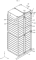
- FIG. 1 is a diagram illustrating a battery rack 10 according to an embodiment of the present disclosure
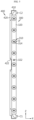
- FIG. 2 is a rear view of the battery rack 10 in FIG. 1
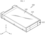
- FIG. 3 is a diagram illustrating a battery module 100 provided in the battery rack 10 in FIG. 1
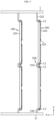
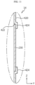
- FIGS. 4 to 6 are diagrams illustrating the coupling relationship between a fire extinguishing agent supply module 300 and a support module 400 provided in the battery rack 10 in FIG. 1 .
- the X-axis direction shown in the drawing may refer to the left-and-right direction
- the Y-axis direction may refer to the front-and-back direction perpendicular to the left-and-right direction on the horizontal plane (XY plane)
- the Z-axis direction may refer to the up-and-down direction perpendicular to both the X-axis direction and the Y-axis direction.
- a battery rack 10 includes a battery module 100, a rack frame 200, a fire extinguishing agent supply module 300, and a support module 400.
- the battery module 100 may include a cell assembly 110 and a module case 120.
- the cell assembly 110 may include at least one battery cell.
- the battery cell may refer to a secondary battery.
- This battery cell may be configured as a pouch-type battery cell, a cylindrical battery cell, or a square-shaped battery cell.
- the battery cell may be a pouch-type battery cell.
- the module case 120 may accommodate the cell assembly 110 therein. To this end, the module case 120 may have an internal accommodation space formed therein to accommodate the cell assembly 110.
- the rack frame 200 may accommodate the battery module 100 therein.
- the rack frame 200 may include an internal accommodation space for accommodating the battery module 100 therein.
- This rack frame 200 may include a main frame 210.
- the fire extinguishing agent supply module 300 may be disposed on one side of the rack frame 200 (e.g., the rear side of the rack frame 200). In addition, the fire extinguishing agent supply module 300 may be connected to the battery module 100.
- this fire extinguishing agent supply module 300 may be connected to the module case 120 of the battery module 100 (see FIG. 7 ).
- the fire extinguishing agent supply module 300 may receive a fire extinguishing agent from an external fire extinguishing agent supply tank (not shown) and spray the same on the cell assembly 110 inside the module case 120.
- the fire extinguishing agent may be a liquid, more specifically water, but is not limited thereto.
- This support module 400 may be coupled to one side of the rack frame 200 such that the fire extinguishing agent supply module 300 faces the battery module 100.
- the support module 400 may be coupled to the main frame 210 described above.
- the support module 400 may be bolted to the rack frame 200 but is not limited to this coupling method.
- the fire extinguishing agent is discharged directly into the battery module 100, when a thermal event occurs in the battery module 100, the thermal event is able to be quickly suppressed.
- the support module 400 is coupled to one side of the rack frame 200 such that the fire extinguishing agent supply module 300 faces the battery module 100, the coupling between the battery module 100 and the fire extinguishing agent supply module 300 may be easily performed, enabling more stable spraying of the fire extinguishing agent.
- the fire extinguishing agent supply module 300 is able to withstand such vibrations. Therefore, more stable control of thermal events may be possible.
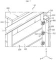
- FIG. 7 is an enlarged view of part A in FIG. 1 .
- a pipe connection member 500 which will be described later, will be omitted from FIG. 7 .
- the fire extinguishing agent supply module 300 may include a nozzle 310 and a fire extinguishing pipe 320.
- the nozzle 310 may be connected to the battery module 100.
- the nozzle 310 may be connected to the module case 120 of the battery module 100.
- a nozzle insertion hole 122 may be formed in the module case 120 of the battery module 100, as shown in FIG. 3 .
- This nozzle insertion hole 122 may be provided in the module case 120 to have a predetermined area such that the nozzle 310 may be inserted into the module case 120.
- At least a portion of the nozzle 310 may be inserted into the module case 120 through the nozzle insertion hole 122.
- This nozzle 310 may receive a fire extinguishing agent from the fire extinguishing agent supply tank described above and spray the same on the cell assembly 110 inside the module case 120.
- the nozzle 310 may include a nozzle body 312 and a nozzle head 314 as shown in FIGS. 4 to 7 .
- the nozzle body 312 may be formed in a substantially cylindrical shape.
- a fire extinguishing agent discharge path may be provided in a hollow form inside the nozzle body 312.
- the nozzle head 314 may be connected to the nozzle body 312 and inserted into the module case 120 through the nozzle insertion hole 122 of the module case 120.
- the nozzle head 314 may be configured as, for example, a glass bulb.
- the nozzle head 314 configured as the glass bulb may be configured to block the fire extinguishing agent discharge path inside the nozzle body 312 at ordinary times and break when a thermal event such as thermal runaway of the cell assembly 110 occurs to discharge the fire extinguishing agent into the module case 120.
- the glass bulb may contain a predetermined liquid (e.g., water) therein. This glass bulb may be configured to break due to volume expansion of the predetermined liquid when the temperature inside the module case 120 rises to a predetermined temperature or more due to thermal runaway of the cell assembly 110.
- the nozzle head 314 may include a separate on-off valve.
- the on-off valve of the nozzle head 314 may be provided on the nozzle head 314 along with a temperature sensor that detects the temperature inside the module case 120.
- the on-off valve may be configured to close the fire extinguishing agent discharge path in the nozzle body 312 at ordinary times and open the fire extinguishing agent discharge path when thermal runaway of the cell assembly 110 occurs, so that the nozzle head 314 may discharge the fire extinguishing agent into the module case 120.
- the temperature sensor detects that the temperature inside the module case 120 rises to a predetermined temperature or more due to the thermal runaway of the cell assembly 110, the on-off valve may open the fire extinguishing agent discharge path.
- the fire extinguishing pipe 320 may be coupled to the support module 400 and connected to the nozzle 310 so as to supply the fire extinguishing agent to the nozzle 310.
- the fire extinguishing pipe 320 may be connected to the nozzle body 312, thereby supplying the fire extinguishing agent to the nozzle head 314.
- the fire extinguishing pipe 320 may be connected to the fire extinguishing agent discharge path inside the nozzle body 312.
- a hole may be formed in the fire extinguishing pipe 320 so as to communicate with the fire extinguishing agent discharge path inside the nozzle body 312.
- the fire extinguishing pipe 320 may be connected to an external fire extinguishing agent supply tank so as to receive the fire extinguishing agent.
- the fire extinguishing pipe 320 may be an extruded pipe formed by extrusion as a single piece, but is not limited thereto.
- the fire extinguishing agent supply module 300 may further include a leak prevention member D.
- the leak prevention member D may be provided on the outer peripheral surface of the nozzle body 312 described above.
- the leak prevention member D may be silicon foam, but is not limited thereto, and any material with good cushioning and compressibility may be applied thereto.
- the leak prevention member D may be made of a material such as rubber, sponge, or the like.
- this leak prevention member D may come into close contact with the outer surface of the module case 120 when the nozzle 310 is connected to the battery module 100. Accordingly, when the fire extinguishing agent is discharged from the nozzle 310, the impact applied to the nozzle 310 and the battery module 100 may be alleviated. In addition, when the fire extinguishing agent is discharged from the nozzle 310, it is possible to prevent the fire extinguishing agent from leaking out of the battery module 100 through the gap between the nozzle 310 and the battery module 100.
- the support module 400 may include a pipe support portion 410 and a frame coupling portion 420.
- the pipe support portion 410 may support the fire extinguishing pipe 320.
- This pipe support portion 410 may be formed in a plate shape.
- the frame coupling portion 420 may be configured to extend from one side of the pipe support portion 410 to face one side of the rack frame 200 and to be coupled to one side of the rack frame 200. Specifically, the frame coupling portion 420 may be coupled to the main frame 210 described above. In this case, the frame coupling portion 420 may be formed in a plate shape. For example, the frame coupling portion 420 may be coupled to the main frame 210 located on the right side of the battery module 100 when viewed in the left-and-right direction of the rack frame 200.
- the plate-shaped frame coupling portion 420 may be coupled to one side of the rack frame 200 such that the portion where the nozzle 310 is connected to the fire extinguishing pipe 320 faces the battery module 100.
- the coupling between the battery module 100 and the nozzle 310 may be easily performed and the vibration applied to the fire extinguishing agent supply module 300 may be minimized, enabling more stable control of thermal events.
- the frame coupling portion 420 described above may be configured to come into surface contact with one side of the rack frame 200.
- the frame coupling portion 420 may be coupled to one side of the rack frame 200 so as to come into close contact therewith.
- the frame coupling portion 420 may be in close contact with one side of the rack frame 200, and at least a portion of the frame coupling portion 420 may be bolted to one side of the rack frame 200.
- the coupling between the rack frame 200 and the support module 400 may be made more stably.
- the frame coupling portion 420 may be formed to extend in the up-and-down direction and may be configured such that its upper and lower ends are coupled to one side of the rack frame 200.
- the frame coupling portion 420 is in surface contact with one side of the rack frame 200, even if only the upper and lower portions thereof are fixed to one side of the rack frame 200, it may be stably fixed to the rack frame 200.
- the pipe support portion 410 may be configured to surround at least a portion of the fire extinguishing pipe 320.
- the pipe support portion 410 may be configured to surround the remaining outer surfaces of the fire extinguishing pipe 320, excluding the side surface thereof facing the battery module 100 (the side surface on which the nozzle 310 is provided), or may be configured to surround some of the remaining outer surfaces of the fire extinguishing pipe 320, excluding the side surface thereof facing the battery module 100 (the side surface on which the nozzle 310 is provided).
- the pipe support portion 410 may be configured to surround the right side surface and upper surface of the fire extinguishing pipe 320 when viewed in the left-and-right direction, front-and-back direction, and up-and-down direction of the rack frame 200.
- the pipe support portion 410 may support the fire extinguishing pipe 320 more stably, and the rigidity of the fire extinguishing agent supply module 300 may be further reinforced in the state where the support module 400 is coupled to the rack frame 200.
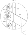
- FIG. 8 is a diagram illustrating the coupling relationship between a rigid reinforcement portion 230 and a fire extinguishing agent supply module 300 provided in the battery rack in FIG. 1 .
- the rack frame 200 may further include a rigid reinforcement portion 230.
- the rigid reinforcement portion 230 may be provided on one side of the rack frame 200 to reinforce the rigidity of the rack frame 200. Specifically, this rigid reinforcement portion 230 may connect a pair of main frames 210 in the left-and-right direction of the battery rack 10, thereby reinforcing the rigidity of the rack frame 200 in the left-and-right direction. For example, both ends of the rigid reinforcement portion 230 may be coupled to the main frame 210 when viewed in the left-and-right direction of the rack frame 200. For example, both ends of the rigid reinforcement portion 230 may be bolted to the main frame 210, but are not limited thereto.
- the fire extinguishing pipe 320 may include a fixing member 322, as shown in FIGS. 4 to 6 and FIG. 8 .
- the fixing member 322 may protrude from the side surface of the fire extinguishing pipe 320 facing the battery module 100 and may be configured to fix the fire extinguishing pipe 320 to the rigid reinforcement portion 230.
- the fixing member 322 may be formed by injection molding with the fire extinguishing pipe 320 when manufacturing the fire extinguishing pipe 320, or may be configured as a separate member and coupled to the fire extinguishing pipe 320.
- the fixing member 322 When the support module 400 is coupled to one side of the rack frame 200, the fixing member 322 may be inserted into a first hole H1 formed in the rigid reinforcement portion 230 toward one side of the rigid reinforcement portion 230 facing the fire extinguishing pipe 320.
- the fixing member 322 inserted into the first hole H1 may be configured to be fixed to the rigid reinforcement portion 230 by a nut inserted into the fixing member 322 toward the other side of the rigid reinforcement portion 230.
- the rigidity of the fire extinguishing agent supply module 300 may be further reinforced in the state in which the support module 400 is coupled to the rack frame 200. Accordingly, vibration applied to the fire extinguishing agent supply module 300 may be minimized, enabling more stable control of thermal events.
- the frame coupling portion 420 may include a recessed portion 422 that is partially recessed to correspond to the height of the rigid reinforcement portion 230.
- This recessed portion 422 when the frame coupling portion 420 is coupled to the rack frame 200, may prevent interference between the rigid reinforcement portion 230 and the frame coupling portion 420.
- the ends of the frame coupling portion 420 which are located above and below the recessed portion 422, may be bolted to one side of the rack frame 200.
- one end of the rigid reinforcement portion 230 may be fitted into the recessed portion 422. This configuration may enable more stable coupling of the support module 400 to the rack frame 200, as well as reducing the cost by reducing the components of the frame coupling portion 420.
- the nozzle 310 facing the rigid reinforcement portion 230 may be configured to be connected to the battery module 100 by passing through the rigid reinforcement portion 230.
- the nozzle 310 facing the rigid reinforcement portion 230 when the support module 400 is coupled to one side of the rack frame 200, may be inserted into a second hole H2 formed in the rigid reinforcement portion 230 toward one side of the rigid reinforcement portion 230 facing the fire extinguishing pipe 320. Accordingly, the nozzle 310 facing the rigid reinforcement portion 230 may be easily connected to the battery module 100 provided at a position facing the rigid reinforcement portion 230.
- a plurality of battery modules 100 may be provided.
- the plurality of battery modules 100 may be stacked in the up-and-down direction so as to be electrically connected to each other.
- the plurality of battery modules 100 may be arranged in two rows while being stacked in the up-and-down direction inside the rack frame 200.
- a plurality of nozzles 310 may be provided.
- the plurality of nozzles 310 may be connected to the fire extinguishing pipe 320 and may be provided along the up-and-down direction of the fire extinguishing pipe 320.
- the nozzles 310 may be configured to correspond to the battery modules 100, respectively. That is, each of the plurality of nozzles 310 may be connected to each battery module 100.
- FIG. 9 is a diagram illustrating the coupling relationship between a fire extinguishing agent supply module 300 and a pipe connection member 500 provided in the battery rack 10 in FIG. 1 .
- a plurality of battery modules 100 may be provided.
- at least one rack frame 200 may be provided.
- at least one fire extinguishing agent supply module 300 and support module 400 may be provided so as to correspond to the rack frame 200.
- a plurality of fire extinguishing agent supply modules 300 and support modules 400 may be configured to correspond to the same.
- the plurality of rack frames 200 may be configured to be stacked in the up-and-down direction.
- the battery rack 10 may further include a pipe connection member 500.
- the pipe connection member 500 may be configured as a flexible pipe.
- This pipe connection member 500 may be configured to adjust the position of the fire extinguishing agent supply module 300 to correspond to the height of the rack frame 200 when the support module 400 is coupled to the rack frame 200.
- the size of the rack frame 200 may also change corresponding thereto.
- the pipe connection member 500 may be configured to connect different fire extinguishing agent supply modules 300 disposed on one sides of the respective rack frames 200.
- the pipe connection member 500 may be configured to connect a supply pipe I, which supplies the fire extinguishing agent to the fire extinguishing agent supply module 300 from the outside (e.g., a fire extinguishing agent supply tank), and the fire extinguishing agent supply module 300.
- the pipe connection member 500 may be configured to connect a discharge pipe O, which receives the fire extinguishing agent from the fire extinguishing agent supply module 300 and discharges the same to the outside, and the fire extinguishing agent supply module 300.
- the supply pipe I may be provided at the top of the plurality of stacked rack frames 200.
- the discharge pipe O may be provided at the bottom of the plurality of stacked rack frames 200.
- This pipe connection member 500 may be made of a flexible material to be adjustable in the degree of bending thereof, so that the position of the fire extinguishing agent supply module 300 may be adjusted corresponding to the changed height of the rack frame 200.
- the position of the fire extinguishing agent supply module 300 may be easily adjusted to correspond to the number of battery modules 100 mounted in the rack frame 200 without changing the configuration of the fire extinguishing agent supply module 300. Accordingly, the overall configuration of the battery rack 10 may be configured more compactly.
- the pipe connection member 500 may include a fire extinguishing pipe connection member 510.
- the fire extinguishing pipe connection member 510 may be configured to connect different fire extinguishing agent supply modules 300 disposed on one sides of the respective rack frames 200.
- the plurality of rack frames 200 may be configured to be stacked in the up-and-down direction.
- the fire extinguishing pipe connection member 510 may connect different fire extinguishing pipes 320 disposed on one sides of the respective rack frames 200.
- the coupling between the fire extinguishing pipe connection member 510 and each fire extinguishing pipe 320 may be performed by a first connector C1.
- This first connector C1 may be a joint for connecting pipes.
- the fire extinguishing pipe connection member 510 may be configured to adjust the degree of bending to correspond to the height of the rack frame 200 when the support module 400 is coupled to the rack frame 200.
- the position of the fire extinguishing agent supply module 300 may be easily adjusted to correspond to the number of battery modules 100 mounted in the rack frame 200 without changing the configuration of the fire extinguishing agent supply module 300. Accordingly, the overall configuration of the battery rack 10 may be configured more compactly.
- the pipe connection member 500 may further include a supply pipe connection member 520 and a discharge pipe connection member 530.
- a single rack frame 200 or a plurality of rack frames may be provided.
- the supply pipe connection member 520 may be configured to connect the supply pipe I and the fire extinguishing agent supply module 300.
- the supply pipe connection member 520 may connect the supply pipe I and the fire extinguishing pipe 320.
- coupling between the supply pipe connection member 520 and the fire extinguishing pipe 320 may be performed by a second connector C2.
- This second connector C2 may be a joint for connecting pipes.
- the discharge pipe connection member 530 may be configured to connect the discharge pipe O and the fire extinguishing agent supply module 300.
- the discharge pipe connection member 530 may connect the discharge pipe O and the fire extinguishing pipe 320.
- coupling between the discharge pipe connection member 530 and the fire extinguishing pipe 320 may be performed by a third connector C3.
- This third connector C3 may be a joint for connecting pipes.
- At least one of the supply pipe connection member 520 and the discharge pipe connection member 530 may be configured to be adjustable in the degree of bending thereof, when the support module 400 is coupled to the rack frame 200, so as to correspond to the height of the rack frame 200.
- the position of the fire extinguishing agent supply module 300 may be easily adjusted to correspond to the number of battery modules 100 mounted in the rack frame 200 without changing the configuration of the fire extinguishing agent supply module 300. Accordingly, the overall configuration of the battery rack 10 may be configured more compactly.
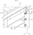
- FIG. 10 is a diagram illustrating a battery rack 12 according to another embodiment of the present disclosure.
- the battery rack 12 according to the present embodiment is similar to the battery rack 10 of the previous embodiment, redundant description of components that are substantially the same or similar to those of the previous embodiment will be omitted, and hereinafter, the differences therebetween will be described.
- the pipe support portion 410 may be configured to surround the remaining outer surfaces of the fire extinguishing pipe 320, excluding the side surface facing the battery module 100 (the side surface provided with the nozzle 310).
- the battery rack 12 may further reinforce the rigidity of the fire extinguishing agent supply module 300 in the state in which the support module 400 is coupled to the rack frame 200 and minimize the exposure of the fire extinguishing pipe 320 to the outside.
- FIG. 11 is a diagram illustrating a battery rack 14 according to another embodiment of the present disclosure.
- the battery rack 14 according to the present embodiment is similar to the battery rack 10 of the previous embodiment, redundant description of components that are substantially the same or similar to those of the previous embodiment will be omitted, and hereinafter, the differences therebetween will be described.
- the frame coupling portion 420 of the support module 400 may further include a pair of flange portions 424.
- the flange portions 424 may be configured to be bent from the ends of the frame coupling portion 420 in the upper and lower portions of the recessed portion 422 in the outward direction of the rack frame 200.
- the pair of flange portions 424 may be configured to face each other in the up-and-down direction.
- the flange portion 424 may be configured to come into surface contact with one end of the rigid reinforcement portion 230 when the frame coupling portion 420 is coupled to the rack frame 200.
- the flange portion 424 may be bolted to one end of the rigid reinforcement portion 230.
- the support module 400 may be more firmly coupled to the rack frame 200.
- the fire extinguishing agent is able to be discharged directly into the battery module 100, so the thermal event of the battery module 100 can be quickly suppressed.
- connection between the battery module 100 and the fire extinguishing agent supply module 300 can be easily made, enabling more stable spray of the fire extinguishing agent.
- the fire extinguishing agent supply module 300 is ensured to withstand such vibrations, so that stable control of thermal events may be possible.
- FIG. 12 is a diagram illustrating an electric power storage system 1 according to an embodiment of the present disclosure.
- the electric power storage system 1 may include at least one battery rack 10 and a rack container 50.
- two or more battery racks 10 may be provided.
- the rack container 50 may include an accommodating space for accommodating at least one battery rack 10.
Landscapes
- Chemical & Material Sciences (AREA)
- Chemical Kinetics & Catalysis (AREA)
- Electrochemistry (AREA)
- General Chemical & Material Sciences (AREA)
- Health & Medical Sciences (AREA)
- Public Health (AREA)
- Business, Economics & Management (AREA)
- Emergency Management (AREA)
- Engineering & Computer Science (AREA)
- Manufacturing & Machinery (AREA)
- Battery Mounting, Suspending (AREA)
- Secondary Cells (AREA)
Abstract
Description
- The present application claims priority to
Korean Patent Application No. 10-2022-0102009 filed on August 16, 2022 - The present disclosure relates to a battery rack and an electric power storage system including the same, and more specifically, to a battery rack capable of effectively controlling thermal events and an electric power storage system including the same.
- Secondary batteries, which are easy to apply depending on the product group and have electrical characteristics such as high energy density and the like, are generally used in electric vehicles (EVs) or hybrid electric vehicles (HEVs) that are driven by an electrical drive source, as well as in portable devices. These secondary batteries are attracting attention as a new energy source for improving eco-friendliness and energy efficiency in that they have the primary advantage of being able to dramatically reduce the use of fossil fuels and in that no by-product is generated due to energy use.
- Types of current secondary batteries widely used include lithium ion batteries, lithium polymer batteries, nickel cadmium batteries, nickel hydrogen batteries, nickel zinc batteries, and the like. The operating voltage of this unit secondary battery cell, that is, the unit battery cell, is approximately 2.5V to 4.5V. Therefore, when an output voltage higher than this is required, a battery pack may be configured by connecting a plurality of battery cells in series. In addition, a battery pack may be configured by connecting multiple battery cells in parallel depending on the charge/discharge capacity required for the battery pack. Accordingly, the number of battery cells included in the battery pack may be set in various ways depending on the required output voltage or charge/discharge capacity.
- Meanwhile, in the case of configuring a battery pack by connecting a plurality of battery cells in series/parallel, a common method is to preferentially configure a battery module including at least one battery cell and then add other components using the at least one battery module, thereby configuring a battery pack or battery rack. Meanwhile, an electric power storage system is configured as an energy source by providing at least one battery rack described above.
- In the case of the battery rack, an abnormality such as a short circuit may occur in some battery cells of a plurality of battery modules and the temperature of the battery cells may continue to increase and exceed a critical temperature according thereto, resulting in a thermal event. If a thermal event occurs in some battery cells as described above, safety issues may arise.
- To solve this problem, conventionally, a water injection system is configured adjacent to the battery rack so as to control thermal events generated in the battery module.
- However, since this conventional water injection system sprays a fire extinguishing agent over a wide area of the battery rack, it is difficult to quickly and effectively control the aforementioned thermal events.
- The present disclosure has been designed to solve the problems of the related art, and therefore the present disclosure is directed to providing a battery rack capable of effectively controlling thermal events and an electric power storage system including the same.
- However, the technical problems to be solved by the present disclosure are not limited to the above-mentioned problems, and other problems not mentioned will be clearly understood by those skilled in the art from the description of the invention below.
- According to one aspect of the present disclosure, there is provided a battery rack including a battery module, a rack frame accommodating the battery module, a fire extinguishing agent supply module disposed on one side of the rack frame and connected to the battery module, and a support module coupled to the one side of the rack frame and configured to support the fire extinguishing agent supply module such that the fire extinguishing agent supply module faces the battery module.
- In an embodiment, the fire extinguishing agent supply module may include a nozzle connected to the battery module, and a fire extinguishing pipe coupled to the support module and connected to the nozzle to supply a fire extinguishing agent to the nozzle, and the support module may include a pipe support portion supporting the fire extinguishing pipe, and a frame coupling portion extending from one side of the pipe support portion so as to face the one side of the rack frame and coupled to the one side of the rack frame.
- In an embodiment, the frame coupling portion may be configured to come into surface contact with the one side of the rack frame.
- In an embodiment, the frame coupling portion may be formed to extend in the up-and-down direction and may be configured such that the upper and lower ends thereof are coupled to the one side of the rack frame.
- In an embodiment, the pipe support portion may be configured to surround at least a portion of the fire extinguishing pipe.
- In an embodiment, the rack frame may include a rigid reinforcement portion provided on the one side of the rack frame so as to reinforce the rigidity of the rack frame, and the fire extinguishing pipe may include a fixing member protruding from a side surface of the fire extinguishing pipe facing the battery module and configured to fix the fire extinguishing pipe to the rigid reinforcement portion.
- In an embodiment, the frame coupling portion may include a recessed portion partially recessed to correspond to the height of the rigid reinforcement portion.
- In an embodiment, the nozzle facing the rigid reinforcement portion may be configured to be connected to the battery module by passing through the rigid reinforcement portion.
- In an embodiment, a plurality of battery modules may be provided, a plurality of nozzles may be provided, and the plurality of nozzles may be configured to respectively correspond to the plurality of battery modules.
- In an embodiment, a plurality of battery modules may be provided, at least one rack frame may be provided, at least one fire extinguishing agent supply module and at least one support module may be provided to correspond to the at least one rack frame, and the battery rack may further include a pipe connection member configured to adjust the position of the fire extinguishing agent supply module to correspond to the height of the rack frame when the support module is coupled to the rack frame.
- In an embodiment, the pipe connection member may include a fire extinguishing pipe connection member configured to connect different fire extinguishing agent supply modules disposed on one sides of respective rack frames, and the fire extinguishing pipe connection member may be configured to be adjustable in the degree of bending to correspond to the height of the rack frame when the support module is coupled to the rack frame.
- In an embodiment, the pipe connection member may further include a supply pipe connection member configured to connect a supply pipe that supplies a fire extinguishing agent to the fire extinguishing agent supply module from the outside and the fire extinguishing agent supply module, and a discharge pipe connection member configured to connect a discharge pipe that receives a fire extinguishing agent from the fire extinguishing agent supply module and discharges the same to the outside and the fire extinguishing agent supply module, and at least one of the supply pipe connection member and the discharge pipe connection member may be configured to be adjustable in the degree of bending to correspond to the height of the rack frame when the support module is coupled to the rack frame.
- In addition, an electric power storage system according to another aspect of the present disclosure includes at least one battery rack according to an embodiment of the present disclosure described above.
- According to the implemented configuration of the present disclosure, the fire extinguishing agent is able to be discharged directly into a battery module, so the thermal event of the battery module may be quickly suppressed.
- In addition, the connection between a battery module and a fire extinguishing agent supply module may be easily made, enabling more stable spray of the fire extinguishing agent.
- Additionally, even when strong vibrations are applied to the entire battery rack due to natural disasters such as earthquakes or typhoons, the fire extinguishing agent supply module is ensured to withstand such vibrations, so that stable control of thermal events may be possible.
- In addition, various other effects may be obtained by various embodiments of the present disclosure. These various effects of the present disclosure will be described in detail in each embodiment, or descriptions of effects that may be easily understood by those skilled in the art will be omitted.
- The accompanying drawings illustrate a preferred embodiment of the present disclosure and, together with the detailed description of the invention below, serve to provide further understanding of the technical features of the present disclosure, and thus, the present disclosure is not construed as being limited to the drawings.
-
FIG. 1 is a diagram illustrating a battery rack according to an embodiment of the present disclosure. -
FIG. 2 is a rear view of the battery rack inFIG. 1 . -
FIG. 3 is a diagram illustrating a battery module provided in the battery rack inFIG. 1 . -
FIGS. 4 to 6 are diagrams illustrating the coupling relationship between a fire extinguishing agent supply module and a support module provided in the battery rack inFIG. 1 . -
FIG. 7 is an enlarged view of part A inFIG. 1 . -
FIG. 8 is a diagram illustrating the coupling relationship between a rigid reinforcement portion and a fire extinguishing agent supply module provided in the battery rack inFIG. 1 . -
FIG. 9 is a diagram illustrating the coupling relationship between a fire extinguishing agent supply module and a pipe connection member provided in the battery rack inFIG. 1 . -
FIG. 10 is a diagram illustrating a battery rack according to another embodiment of the present disclosure. -
FIG. 11 is a diagram illustrating a battery rack according to another embodiment of the present disclosure. -
FIG. 12 is a diagram illustrating an electric power storage system according to an embodiment of the present disclosure. - Hereinafter, preferred embodiments of the present disclosure will be described in detail with reference to the accompanying drawings. Prior to the description, it should be understood that the terms used in the specification and the appended claims should not be construed as limited to general and dictionary meanings, but interpreted based on the meanings and concepts corresponding to technical aspects of the present disclosure on the basis of the principle that the inventor is allowed to define terms appropriately for the best explanation.
- Therefore, the configuration proposed in the embodiments and drawings herein is just a preferable example of the present disclosure and does not indicate the entirety of the technical concept of the present disclosure, so it should be understood that other equivalents and modifications could be made thereto without departing from the scope of the disclosure.
-
FIG. 1 is a diagram illustrating abattery rack 10 according to an embodiment of the present disclosure,FIG. 2 is a rear view of thebattery rack 10 inFIG. 1 ,FIG. 3 is a diagram illustrating abattery module 100 provided in thebattery rack 10 inFIG. 1 , andFIGS. 4 to 6 are diagrams illustrating the coupling relationship between a fire extinguishingagent supply module 300 and asupport module 400 provided in thebattery rack 10 inFIG. 1 . - In an embodiment of the present disclosure, the X-axis direction shown in the drawing may refer to the left-and-right direction, the Y-axis direction may refer to the front-and-back direction perpendicular to the left-and-right direction on the horizontal plane (XY plane), and the Z-axis direction may refer to the up-and-down direction perpendicular to both the X-axis direction and the Y-axis direction.
- Referring to
FIGS. 1 to 6 , abattery rack 10 according to an embodiment of the present disclosure includes abattery module 100, arack frame 200, a fire extinguishingagent supply module 300, and asupport module 400. - The
battery module 100 may include acell assembly 110 and amodule case 120. - The
cell assembly 110 may include at least one battery cell. Here, the battery cell may refer to a secondary battery. This battery cell may be configured as a pouch-type battery cell, a cylindrical battery cell, or a square-shaped battery cell. For example, the battery cell may be a pouch-type battery cell. - The
module case 120 may accommodate thecell assembly 110 therein. To this end, themodule case 120 may have an internal accommodation space formed therein to accommodate thecell assembly 110. - The
rack frame 200 may accommodate thebattery module 100 therein. To this end, therack frame 200 may include an internal accommodation space for accommodating thebattery module 100 therein. - This
rack frame 200 may include amain frame 210. - The
main frame 210 may be formed to extend in the up-and-down direction. Thismain frame 210 may be configured in a pillar shape. Thismain frame 210 may form an accommodating space capable of accommodating thebattery modules 100 inside therack frame 200. Although not shown in detail, therack frame 200 may further include a horizontal plate (not shown) connected to themain frame 210 and disposed in the horizontal direction. In this case, thebattery module 100 may be placed on the horizontal plate and received inside therack frame 200. - The fire extinguishing
agent supply module 300 may be disposed on one side of the rack frame 200 (e.g., the rear side of the rack frame 200). In addition, the fire extinguishingagent supply module 300 may be connected to thebattery module 100. - Specifically, this fire extinguishing
agent supply module 300 may be connected to themodule case 120 of the battery module 100 (seeFIG. 7 ). In addition, the fire extinguishingagent supply module 300 may receive a fire extinguishing agent from an external fire extinguishing agent supply tank (not shown) and spray the same on thecell assembly 110 inside themodule case 120. For example, the fire extinguishing agent may be a liquid, more specifically water, but is not limited thereto. - The
support module 400 may support the fire extinguishingagent supply module 300. For example, the fire extinguishingagent supply module 300 may be bolted to thesupport module 400, but is not limited to this coupling method. - This
support module 400 may be coupled to one side of therack frame 200 such that the fire extinguishingagent supply module 300 faces thebattery module 100. Specifically, thesupport module 400 may be coupled to themain frame 210 described above. For example, thesupport module 400 may be bolted to therack frame 200 but is not limited to this coupling method. - According to this implemented configuration of the present disclosure, since the fire extinguishing agent is discharged directly into the
battery module 100, when a thermal event occurs in thebattery module 100, the thermal event is able to be quickly suppressed. - In addition, since the
support module 400 is coupled to one side of therack frame 200 such that the fire extinguishingagent supply module 300 faces thebattery module 100, the coupling between thebattery module 100 and the fire extinguishingagent supply module 300 may be easily performed, enabling more stable spraying of the fire extinguishing agent. - In addition, by directly connecting the
support module 400 that supports the fire extinguishingagent supply module 300 to therack frame 200, even when strong vibrations are applied to theentire battery rack 10 due to natural disasters such as earthquakes or typhoons, the fire extinguishingagent supply module 300 is able to withstand such vibrations. Therefore, more stable control of thermal events may be possible. -
FIG. 7 is an enlarged view of part A inFIG. 1 . In this case, apipe connection member 500, which will be described later, will be omitted fromFIG. 7 . - Referring to
FIGS. 1 ,2 , and4 to 7 , the fire extinguishingagent supply module 300 may include anozzle 310 and afire extinguishing pipe 320. - The
nozzle 310 may be connected to thebattery module 100. In this case, thenozzle 310 may be connected to themodule case 120 of thebattery module 100. Specifically, anozzle insertion hole 122 may be formed in themodule case 120 of thebattery module 100, as shown inFIG. 3 . Thisnozzle insertion hole 122 may be provided in themodule case 120 to have a predetermined area such that thenozzle 310 may be inserted into themodule case 120. - At least a portion of the
nozzle 310 may be inserted into themodule case 120 through thenozzle insertion hole 122. Thisnozzle 310 may receive a fire extinguishing agent from the fire extinguishing agent supply tank described above and spray the same on thecell assembly 110 inside themodule case 120. - In addition, the
nozzle 310 may include anozzle body 312 and anozzle head 314 as shown inFIGS. 4 to 7 . - The
nozzle body 312 may be formed in a substantially cylindrical shape. In addition, a fire extinguishing agent discharge path may be provided in a hollow form inside thenozzle body 312. - The
nozzle head 314 may be connected to thenozzle body 312 and inserted into themodule case 120 through thenozzle insertion hole 122 of themodule case 120. - In addition, the
nozzle head 314 may be configured as, for example, a glass bulb. Thenozzle head 314 configured as the glass bulb may be configured to block the fire extinguishing agent discharge path inside thenozzle body 312 at ordinary times and break when a thermal event such as thermal runaway of thecell assembly 110 occurs to discharge the fire extinguishing agent into themodule case 120. For example, the glass bulb may contain a predetermined liquid (e.g., water) therein. This glass bulb may be configured to break due to volume expansion of the predetermined liquid when the temperature inside themodule case 120 rises to a predetermined temperature or more due to thermal runaway of thecell assembly 110. - Alternatively, the
nozzle head 314 may include a separate on-off valve. The on-off valve of thenozzle head 314 may be provided on thenozzle head 314 along with a temperature sensor that detects the temperature inside themodule case 120. Accordingly, the on-off valve may be configured to close the fire extinguishing agent discharge path in thenozzle body 312 at ordinary times and open the fire extinguishing agent discharge path when thermal runaway of thecell assembly 110 occurs, so that thenozzle head 314 may discharge the fire extinguishing agent into themodule case 120. For example, if the temperature sensor detects that the temperature inside themodule case 120 rises to a predetermined temperature or more due to the thermal runaway of thecell assembly 110, the on-off valve may open the fire extinguishing agent discharge path. - The
fire extinguishing pipe 320 may be coupled to thesupport module 400 and connected to thenozzle 310 so as to supply the fire extinguishing agent to thenozzle 310. - Specifically, the
fire extinguishing pipe 320 may be connected to thenozzle body 312, thereby supplying the fire extinguishing agent to thenozzle head 314. In this case, thefire extinguishing pipe 320 may be connected to the fire extinguishing agent discharge path inside thenozzle body 312. In particular, as shown inFIG. 4 , a hole may be formed in thefire extinguishing pipe 320 so as to communicate with the fire extinguishing agent discharge path inside thenozzle body 312. - In addition, the
fire extinguishing pipe 320 may be connected to an external fire extinguishing agent supply tank so as to receive the fire extinguishing agent. For example, thefire extinguishing pipe 320 may be an extruded pipe formed by extrusion as a single piece, but is not limited thereto. - Additionally, the fire extinguishing
agent supply module 300 may further include a leak prevention member D. The leak prevention member D may be provided on the outer peripheral surface of thenozzle body 312 described above. For example, the leak prevention member D may be silicon foam, but is not limited thereto, and any material with good cushioning and compressibility may be applied thereto. For example, the leak prevention member D may be made of a material such as rubber, sponge, or the like. - As shown in
FIG. 7 , this leak prevention member D may come into close contact with the outer surface of themodule case 120 when thenozzle 310 is connected to thebattery module 100. Accordingly, when the fire extinguishing agent is discharged from thenozzle 310, the impact applied to thenozzle 310 and thebattery module 100 may be alleviated. In addition, when the fire extinguishing agent is discharged from thenozzle 310, it is possible to prevent the fire extinguishing agent from leaking out of thebattery module 100 through the gap between thenozzle 310 and thebattery module 100. - In addition, as shown in
FIGS. 1 ,2 , and4 to 7 , thesupport module 400 may include apipe support portion 410 and aframe coupling portion 420. - The
pipe support portion 410 may support thefire extinguishing pipe 320. Thispipe support portion 410 may be formed in a plate shape. - The
frame coupling portion 420 may be configured to extend from one side of thepipe support portion 410 to face one side of therack frame 200 and to be coupled to one side of therack frame 200. Specifically, theframe coupling portion 420 may be coupled to themain frame 210 described above. In this case, theframe coupling portion 420 may be formed in a plate shape. For example, theframe coupling portion 420 may be coupled to themain frame 210 located on the right side of thebattery module 100 when viewed in the left-and-right direction of therack frame 200. - That is, the plate-shaped
frame coupling portion 420 may be coupled to one side of therack frame 200 such that the portion where thenozzle 310 is connected to thefire extinguishing pipe 320 faces thebattery module 100. - Accordingly, the coupling between the
battery module 100 and thenozzle 310 may be easily performed and the vibration applied to the fire extinguishingagent supply module 300 may be minimized, enabling more stable control of thermal events. - Referring to
FIGS. 1 ,2 , and4 to 7 , theframe coupling portion 420 described above may be configured to come into surface contact with one side of therack frame 200. - That is, since the
frame coupling portion 420 is formed in a plate shape to have a predetermined area, theframe coupling portion 420 may be coupled to one side of therack frame 200 so as to come into close contact therewith. For example, theframe coupling portion 420 may be in close contact with one side of therack frame 200, and at least a portion of theframe coupling portion 420 may be bolted to one side of therack frame 200. - According to the above implemented configuration, the coupling between the
rack frame 200 and thesupport module 400 may be made more stably. - In particular, the
frame coupling portion 420 may be formed to extend in the up-and-down direction and may be configured such that its upper and lower ends are coupled to one side of therack frame 200. - As described above, since the
frame coupling portion 420 is in surface contact with one side of therack frame 200, even if only the upper and lower portions thereof are fixed to one side of therack frame 200, it may be stably fixed to therack frame 200. - Accordingly, it is possible to minimize fastening components for coupling the
support module 400 to therack frame 200, thereby reducing work time and manufacturing costs. - Referring back to
FIGS. 4 to 7 , thepipe support portion 410 may be configured to surround at least a portion of thefire extinguishing pipe 320. - For example, the
pipe support portion 410 may be configured to surround the remaining outer surfaces of thefire extinguishing pipe 320, excluding the side surface thereof facing the battery module 100 (the side surface on which thenozzle 310 is provided), or may be configured to surround some of the remaining outer surfaces of thefire extinguishing pipe 320, excluding the side surface thereof facing the battery module 100 (the side surface on which thenozzle 310 is provided). - For example, the
pipe support portion 410 may be configured to surround the right side surface and upper surface of thefire extinguishing pipe 320 when viewed in the left-and-right direction, front-and-back direction, and up-and-down direction of therack frame 200. - Accordingly, the
pipe support portion 410 may support thefire extinguishing pipe 320 more stably, and the rigidity of the fire extinguishingagent supply module 300 may be further reinforced in the state where thesupport module 400 is coupled to therack frame 200. -
FIG. 8 is a diagram illustrating the coupling relationship between arigid reinforcement portion 230 and a fire extinguishingagent supply module 300 provided in the battery rack inFIG. 1 . - Referring back to
FIGS. 1 ,2 , and4 to 8 , therack frame 200 may further include arigid reinforcement portion 230. - The
rigid reinforcement portion 230 may be provided on one side of therack frame 200 to reinforce the rigidity of therack frame 200. Specifically, thisrigid reinforcement portion 230 may connect a pair ofmain frames 210 in the left-and-right direction of thebattery rack 10, thereby reinforcing the rigidity of therack frame 200 in the left-and-right direction. For example, both ends of therigid reinforcement portion 230 may be coupled to themain frame 210 when viewed in the left-and-right direction of therack frame 200. For example, both ends of therigid reinforcement portion 230 may be bolted to themain frame 210, but are not limited thereto. - In addition, the
fire extinguishing pipe 320 may include a fixingmember 322, as shown inFIGS. 4 to 6 andFIG. 8 . - The fixing
member 322 may protrude from the side surface of thefire extinguishing pipe 320 facing thebattery module 100 and may be configured to fix thefire extinguishing pipe 320 to therigid reinforcement portion 230. For example, the fixingmember 322 may be formed by injection molding with thefire extinguishing pipe 320 when manufacturing thefire extinguishing pipe 320, or may be configured as a separate member and coupled to thefire extinguishing pipe 320. - When the
support module 400 is coupled to one side of therack frame 200, the fixingmember 322 may be inserted into a first hole H1 formed in therigid reinforcement portion 230 toward one side of therigid reinforcement portion 230 facing thefire extinguishing pipe 320. Although not shown, the fixingmember 322 inserted into the first hole H1 may be configured to be fixed to therigid reinforcement portion 230 by a nut inserted into the fixingmember 322 toward the other side of therigid reinforcement portion 230. - According to this implemented configuration of the present disclosure, since the side of the
fire extinguishing pipe 320 facing thebattery module 100 is fixed to therack frame 200, the rigidity of the fire extinguishingagent supply module 300 may be further reinforced in the state in which thesupport module 400 is coupled to therack frame 200. Accordingly, vibration applied to the fire extinguishingagent supply module 300 may be minimized, enabling more stable control of thermal events. - In addition, the
frame coupling portion 420 may include a recessedportion 422 that is partially recessed to correspond to the height of therigid reinforcement portion 230. - This recessed
portion 422, when theframe coupling portion 420 is coupled to therack frame 200, may prevent interference between therigid reinforcement portion 230 and theframe coupling portion 420. In this case, the ends of theframe coupling portion 420, which are located above and below the recessedportion 422, may be bolted to one side of therack frame 200. - In addition, when the
frame coupling portion 420 is coupled to therack frame 200, one end of therigid reinforcement portion 230 may be fitted into the recessedportion 422. This configuration may enable more stable coupling of thesupport module 400 to therack frame 200, as well as reducing the cost by reducing the components of theframe coupling portion 420. - In addition, the
nozzle 310 facing therigid reinforcement portion 230 may be configured to be connected to thebattery module 100 by passing through therigid reinforcement portion 230. - Specifically, the
nozzle 310 facing therigid reinforcement portion 230, when thesupport module 400 is coupled to one side of therack frame 200, may be inserted into a second hole H2 formed in therigid reinforcement portion 230 toward one side of therigid reinforcement portion 230 facing thefire extinguishing pipe 320. Accordingly, thenozzle 310 facing therigid reinforcement portion 230 may be easily connected to thebattery module 100 provided at a position facing therigid reinforcement portion 230. - According to this implemented configuration, when the
rigid reinforcement portion 230 is provided in therack frame 200, interference between therigid reinforcement portion 230 and thenozzle 310 may be prevented, and a portion of thenozzle 310 may be inserted into therigid reinforcement portion 230, so that therack frame 200 may support the fire extinguishingagent supply module 300 more stably. - Referring back to
FIGS. 1 ,2 , and4 to 8 , a plurality ofbattery modules 100 may be provided. The plurality ofbattery modules 100 may be stacked in the up-and-down direction so as to be electrically connected to each other. For example, the plurality ofbattery modules 100 may be arranged in two rows while being stacked in the up-and-down direction inside therack frame 200. - In addition, a plurality of
nozzles 310 may be provided. The plurality ofnozzles 310 may be connected to thefire extinguishing pipe 320 and may be provided along the up-and-down direction of thefire extinguishing pipe 320. - In addition, the
nozzles 310 may be configured to correspond to thebattery modules 100, respectively. That is, each of the plurality ofnozzles 310 may be connected to eachbattery module 100. - According to this implemented configuration, even when a thermal event occurs in the plurality of
battery modules 100, it is possible to more quickly control the thermal event. -
FIG. 9 is a diagram illustrating the coupling relationship between a fire extinguishingagent supply module 300 and apipe connection member 500 provided in thebattery rack 10 inFIG. 1 . - Referring to
FIGS. 1 ,2 , and4 to 9 , a plurality ofbattery modules 100 may be provided. In addition, at least onerack frame 200 may be provided. In addition, at least one fire extinguishingagent supply module 300 andsupport module 400 may be provided so as to correspond to therack frame 200. For example, in the case where a plurality ofrack frame 200 is provided, a plurality of fire extinguishingagent supply modules 300 and supportmodules 400 may be configured to correspond to the same. Meanwhile, the plurality of rack frames 200 may be configured to be stacked in the up-and-down direction. - In addition, the
battery rack 10 may further include apipe connection member 500. For example, thepipe connection member 500 may be configured as a flexible pipe. - This
pipe connection member 500 may be configured to adjust the position of the fire extinguishingagent supply module 300 to correspond to the height of therack frame 200 when thesupport module 400 is coupled to therack frame 200. - For example, if the number of
battery modules 100 constituting thebattery rack 10 changes, the size of therack frame 200 may also change corresponding thereto. - Specifically, the
pipe connection member 500 may be configured to connect different fire extinguishingagent supply modules 300 disposed on one sides of the respective rack frames 200. In addition, thepipe connection member 500 may be configured to connect a supply pipe I, which supplies the fire extinguishing agent to the fire extinguishingagent supply module 300 from the outside (e.g., a fire extinguishing agent supply tank), and the fire extinguishingagent supply module 300. In addition, thepipe connection member 500 may be configured to connect a discharge pipe O, which receives the fire extinguishing agent from the fire extinguishingagent supply module 300 and discharges the same to the outside, and the fire extinguishingagent supply module 300. - For example, in the case where a plurality of rack frames 200 is provided, the supply pipe I may be provided at the top of the plurality of stacked rack frames 200. In addition, the discharge pipe O may be provided at the bottom of the plurality of stacked rack frames 200.
- This
pipe connection member 500 may be made of a flexible material to be adjustable in the degree of bending thereof, so that the position of the fire extinguishingagent supply module 300 may be adjusted corresponding to the changed height of therack frame 200. - According to this implemented configuration of the present disclosure, the position of the fire extinguishing
agent supply module 300 may be easily adjusted to correspond to the number ofbattery modules 100 mounted in therack frame 200 without changing the configuration of the fire extinguishingagent supply module 300. Accordingly, the overall configuration of thebattery rack 10 may be configured more compactly. - More specifically, the
pipe connection member 500 may include a fire extinguishingpipe connection member 510. - The fire extinguishing
pipe connection member 510 may be configured to connect different fire extinguishingagent supply modules 300 disposed on one sides of the respective rack frames 200. In this case, the plurality of rack frames 200 may be configured to be stacked in the up-and-down direction. - Specifically, the fire extinguishing
pipe connection member 510 may connect differentfire extinguishing pipes 320 disposed on one sides of the respective rack frames 200. In this case, the coupling between the fire extinguishingpipe connection member 510 and eachfire extinguishing pipe 320 may be performed by a first connector C1. This first connector C1 may be a joint for connecting pipes. - The fire extinguishing
pipe connection member 510 may be configured to adjust the degree of bending to correspond to the height of therack frame 200 when thesupport module 400 is coupled to therack frame 200. - Accordingly, in a structure in which the
rack frame 200 is stacked in the up-and-down direction, the position of the fire extinguishingagent supply module 300 may be easily adjusted to correspond to the number ofbattery modules 100 mounted in therack frame 200 without changing the configuration of the fire extinguishingagent supply module 300. Accordingly, the overall configuration of thebattery rack 10 may be configured more compactly. - In addition, the
pipe connection member 500 may further include a supplypipe connection member 520 and a dischargepipe connection member 530. In this case, asingle rack frame 200 or a plurality of rack frames may be provided. - The supply
pipe connection member 520 may be configured to connect the supply pipe I and the fire extinguishingagent supply module 300. - Specifically, the supply
pipe connection member 520 may connect the supply pipe I and thefire extinguishing pipe 320. In this case, coupling between the supplypipe connection member 520 and thefire extinguishing pipe 320 may be performed by a second connector C2. This second connector C2 may be a joint for connecting pipes. - The discharge
pipe connection member 530 may be configured to connect the discharge pipe O and the fire extinguishingagent supply module 300. - Specifically, the discharge
pipe connection member 530 may connect the discharge pipe O and thefire extinguishing pipe 320. In this case, coupling between the dischargepipe connection member 530 and thefire extinguishing pipe 320 may be performed by a third connector C3. This third connector C3 may be a joint for connecting pipes. - At least one of the supply
pipe connection member 520 and the dischargepipe connection member 530 may be configured to be adjustable in the degree of bending thereof, when thesupport module 400 is coupled to therack frame 200, so as to correspond to the height of therack frame 200. - Accordingly, the position of the fire extinguishing
agent supply module 300 may be easily adjusted to correspond to the number ofbattery modules 100 mounted in therack frame 200 without changing the configuration of the fire extinguishingagent supply module 300. Accordingly, the overall configuration of thebattery rack 10 may be configured more compactly. -
FIG. 10 is a diagram illustrating abattery rack 12 according to another embodiment of the present disclosure. - Since the
battery rack 12 according to the present embodiment is similar to thebattery rack 10 of the previous embodiment, redundant description of components that are substantially the same or similar to those of the previous embodiment will be omitted, and hereinafter, the differences therebetween will be described. - Referring to
FIG. 10 , in thebattery rack 12, thepipe support portion 410 may be configured to surround the remaining outer surfaces of thefire extinguishing pipe 320, excluding the side surface facing the battery module 100 (the side surface provided with the nozzle 310). - Therefore, the
battery rack 12 according to the present embodiment may further reinforce the rigidity of the fire extinguishingagent supply module 300 in the state in which thesupport module 400 is coupled to therack frame 200 and minimize the exposure of thefire extinguishing pipe 320 to the outside. -
FIG. 11 is a diagram illustrating abattery rack 14 according to another embodiment of the present disclosure. - Since the
battery rack 14 according to the present embodiment is similar to thebattery rack 10 of the previous embodiment, redundant description of components that are substantially the same or similar to those of the previous embodiment will be omitted, and hereinafter, the differences therebetween will be described. - Referring to
FIG. 11 , in thebattery rack 14, theframe coupling portion 420 of thesupport module 400 may further include a pair offlange portions 424. - Specifically, referring back to
FIGS. 1 ,4 to 6 , and8 together withFIG. 11 , theflange portions 424 may be configured to be bent from the ends of theframe coupling portion 420 in the upper and lower portions of the recessedportion 422 in the outward direction of therack frame 200. The pair offlange portions 424 may be configured to face each other in the up-and-down direction. - In this case, the
flange portion 424 may be configured to come into surface contact with one end of therigid reinforcement portion 230 when theframe coupling portion 420 is coupled to therack frame 200. For example, theflange portion 424 may be bolted to one end of therigid reinforcement portion 230. - With this configuration, in the
battery rack 14 according to the present embodiment, thesupport module 400 may be more firmly coupled to therack frame 200. - As described above, according to the embodiments of the present disclosure, the fire extinguishing agent is able to be discharged directly into the
battery module 100, so the thermal event of thebattery module 100 can be quickly suppressed. - In addition, the connection between the
battery module 100 and the fire extinguishingagent supply module 300 can be easily made, enabling more stable spray of the fire extinguishing agent. - Additionally, even when strong vibrations are applied to the
entire battery rack agent supply module 300 is ensured to withstand such vibrations, so that stable control of thermal events may be possible. -
FIG. 12 is a diagram illustrating an electricpower storage system 1 according to an embodiment of the present disclosure. - Referring to
FIG. 12 , the electricpower storage system 1 may include at least onebattery rack 10 and arack container 50. - In an embodiment, two or
more battery racks 10 may be provided. - In addition, the
rack container 50 may include an accommodating space for accommodating at least onebattery rack 10. - As described above, although the present disclosure has been described with reference to specific embodiments and drawings, the present disclosure is not limited thereto, and it is obvious that various modifications and changes may be conducted by those skilled in the art to which the present disclosure pertains without departing from the scope equivalent to the technical concept of the present disclosure and the claims to be described below.
- Meanwhile, although terms indicating directions such as up, down, left, right, front, and back are used in the present disclosure, these terms are only for convenience of explanation and It is obvious to those skilled in the art that the terms may vary depending on the location of the subject or the location of the observer.
Claims (13)
- A battery rack comprising:a battery module;a rack frame configured to accommodate the battery module;a fire extinguishing agent supply module disposed on one side of the rack frame and connected to the battery module; anda support module coupled to the one side of the rack frame and configured to support the fire extinguishing agent supply module such that the fire extinguishing agent supply module faces the battery module.
- The battery rack according to claim 1,
wherein the fire extinguishing agent supply module comprises:a nozzle connected to the battery module; anda fire extinguishing pipe coupled to the support module and connected to the nozzle to supply a fire extinguishing agent to the nozzle, andwherein the support module comprises:a pipe support portion configured to support the fire extinguishing pipe; anda frame coupling portion extending from one side of the pipe support portion so as to face the one side of the rack frame and coupled to the one side of the rack frame. - The battery rack according to claim 2,
wherein the frame coupling portion is configured to come into surface contact with the one side of the rack frame. - The battery rack according to claim 3,
wherein the frame coupling portion is formed to extend in the up-and-down direction and is configured such that the upper and lower ends thereof are coupled to the one side of the rack frame. - The battery rack according to claim 2,
wherein the pipe support portion is configured to surround at least a portion of the fire extinguishing pipe. - The battery rack according to claim 2,wherein the rack frame comprisesa rigid reinforcement portion provided on the one side of the rack frame so as to reinforce the rigidity of the rack frame, andwherein the fire extinguishing pipe comprisesa fixing member protruding from a side surface of the fire extinguishing pipe facing the battery module and configured to fix the fire extinguishing pipe to the rigid reinforcement portion.
- The battery rack according to claim 6,wherein the frame coupling portion comprisesa recessed portion partially recessed to correspond to the height of the rigid reinforcement portion.
- The battery rack according to claim 6,
wherein the nozzle facing the rigid reinforcement portion is configured to be connected to the battery module by passing through the rigid reinforcement portion. - The battery rack according to claim 2,wherein a plurality of battery modules is provided,wherein a plurality of nozzles is provided, andwherein the plurality of nozzles are configured to respectively correspond to the plurality of battery modules.
- The battery rack according to claim 1,wherein a plurality of battery modules is provided,wherein at least one rack frame is provided,wherein at least one fire extinguishing agent supply module and at least one support module are provided to correspond to the at least one rack frame, andwherein the battery rack further comprisesa pipe connection member configured to adjust the position of the fire extinguishing agent supply module so as to correspond to the height of the rack frame when the support module is coupled to the rack frame.
- The battery rack according to claim 10,wherein the pipe connection member comprisesa fire extinguishing pipe connection member configured to connect different fire extinguishing agent supply modules disposed on one sides of respective rack frames, andwherein the fire extinguishing pipe connection member is configured to be adjustable in the degree of bending to correspond to the height of the rack frame when the support module is coupled to the rack frame.
- The battery rack according to claim 10,
wherein the pipe connection member further comprises:a supply pipe connection member configured to connect a supply pipe that supplies a fire extinguishing agent to the fire extinguishing agent supply module from the outside and the fire extinguishing agent supply module; anda discharge pipe connection member configured to connect a discharge pipe that receives a fire extinguishing agent from the fire extinguishing agent supply module and discharges the same to the outside and the fire extinguishing agent supply module, andwherein at least one of the supply pipe connection member and the discharge pipe connection member is configured to be adjustable in the degree of bending to correspond to the height of the rack frame when the support module is coupled to the rack frame. - An electric power storage system comprising at least one battery rack according to any one of claims 1 to 12.
Applications Claiming Priority (2)
| Application Number | Priority Date | Filing Date | Title |
|---|---|---|---|
| KR1020220102009A KR20240023825A (en) | 2022-08-16 | 2022-08-16 | Battery rack and energy storage system including the same |
| PCT/KR2023/010224 WO2024039079A1 (en) | 2022-08-16 | 2023-07-17 | Battery rack and energy storage system including same |
Publications (2)
| Publication Number | Publication Date |
|---|---|
| EP4447211A1 true EP4447211A1 (en) | 2024-10-16 |
| EP4447211A4 EP4447211A4 (en) | 2025-06-11 |
Family
ID=89941862
Family Applications (1)
| Application Number | Title | Priority Date | Filing Date |
|---|---|---|---|
| EP23855050.3A Pending EP4447211A4 (en) | 2022-08-16 | 2023-07-17 | BATTERY PACK AND ENERGY STORAGE SYSTEM COMPRISING SAME |
Country Status (7)
| Country | Link |
|---|---|
| US (1) | US20250032834A1 (en) |
| EP (1) | EP4447211A4 (en) |
| JP (1) | JP2025515998A (en) |
| KR (1) | KR20240023825A (en) |
| CN (1) | CN118402125A (en) |
| AU (1) | AU2023327731A1 (en) |
| WO (1) | WO2024039079A1 (en) |
Family Cites Families (8)
| Publication number | Priority date | Publication date | Assignee | Title |
|---|---|---|---|---|
| KR101720278B1 (en) * | 2015-03-09 | 2017-03-28 | 주식회사 태산하이텍 | Rack housing for module battery of power storage system |
| JP2019075191A (en) * | 2016-03-08 | 2019-05-16 | パナソニックIpマネジメント株式会社 | Power storage device |
| CN209544545U (en) * | 2018-11-22 | 2019-10-25 | 浙江杭可科技股份有限公司 | A kind of column lithium ion battery component capacitive equipment |
| KR102775048B1 (en) * | 2019-09-05 | 2025-02-27 | 주식회사 엘지에너지솔루션 | Battery Pack Having Fire Extinguishing Unit |
| PL4002551T3 (en) * | 2019-11-08 | 2025-03-17 | Lg Energy Solution, Ltd. | Battery rack and power storage device comprising same |
| PL4207429T3 (en) * | 2020-10-05 | 2025-07-28 | Lg Energy Solution, Ltd. | Battery rack, energy storage system, and power generation system |
| KR102841554B1 (en) * | 2020-10-19 | 2025-08-01 | 주식회사 엘지에너지솔루션 | Battery Rack, Energy Storage System, and Power Generation System |
| KR20220102009A (en) | 2021-01-12 | 2022-07-19 | 삼성전자주식회사 | Electronic device and operation method of electronic device |
-
2022
- 2022-08-16 KR KR1020220102009A patent/KR20240023825A/en active Pending
-
2023
- 2023-07-17 WO PCT/KR2023/010224 patent/WO2024039079A1/en not_active Ceased
- 2023-07-17 CN CN202380015822.4A patent/CN118402125A/en active Pending
- 2023-07-17 EP EP23855050.3A patent/EP4447211A4/en active Pending
- 2023-07-17 JP JP2024563121A patent/JP2025515998A/en active Pending
- 2023-07-17 US US18/718,750 patent/US20250032834A1/en active Pending
- 2023-07-17 AU AU2023327731A patent/AU2023327731A1/en active Pending
Also Published As
| Publication number | Publication date |
|---|---|
| AU2023327731A1 (en) | 2024-08-01 |
| US20250032834A1 (en) | 2025-01-30 |
| EP4447211A4 (en) | 2025-06-11 |
| CN118402125A (en) | 2024-07-26 |
| WO2024039079A1 (en) | 2024-02-22 |
| JP2025515998A (en) | 2025-05-23 |
| KR20240023825A (en) | 2024-02-23 |
Similar Documents
| Publication | Publication Date | Title |
|---|---|---|
| US12294071B2 (en) | Battery pack incorporating battery module and rigid beam and adopting reverse assembling | |
| US12252000B2 (en) | Battery pack with efficient cooling path structure and improved safety and vehicle including the same | |
| JP7069312B2 (en) | Battery pack with connection plate | |
| JP7453376B2 (en) | Battery packs and automobiles containing them | |
| US12374745B2 (en) | Battery module, and battery pack and vehicle including battery module | |
| JP7457129B2 (en) | Housing, battery group and device | |
| US20190181405A1 (en) | Battery module including cross beam and battery pack comprising the same | |
| US20250183413A1 (en) | Battery rack and power storage device comprising same | |
| US20220399578A1 (en) | Sub pack comprising multiple unit modules and bms assembly, and battery pack comprising same | |
| US20220263183A1 (en) | Battery pack having integrated mechanical and electrical fixing structure of battery modules | |
| EP4160789A1 (en) | Battery pack | |
| JP2022508487A (en) | Battery packs and electronic devices with connection plates and automobiles | |
| EP4191734B1 (en) | Battery rack, power storage device, and power generation system | |
| KR102092917B1 (en) | Battery pack and energy storage system comprising the battery pack | |
| US20250032834A1 (en) | Battery rack and electric power storage system including same | |
| KR102660832B1 (en) | Battery pack and vehicle comprising the battery pack | |
| KR102178719B1 (en) | Battery rack and energy storage system comprising the battery rack | |
| KR102088974B1 (en) | Battery module, battery pack comprising the battery module and energy storage system comprising the battery pack | |
| KR20210133566A (en) | Battery module and battery pack including the same | |
| EP4742369A1 (en) | Battery pack and vehicle comprising same | |
| KR20240030838A (en) | Battery rack and energy storage system including the same | |
| KR20250078140A (en) | Battery pack and vehicle comprising the battery pack | |
| CN120548639A (en) | Battery pack and vehicle including the same | |
| CN120752805A (en) | Battery components |
Legal Events
| Date | Code | Title | Description |
|---|---|---|---|
| STAA | Information on the status of an ep patent application or granted ep patent |
Free format text: STATUS: THE INTERNATIONAL PUBLICATION HAS BEEN MADE |
|
| PUAI | Public reference made under article 153(3) epc to a published international application that has entered the european phase |
Free format text: ORIGINAL CODE: 0009012 |
|
| STAA | Information on the status of an ep patent application or granted ep patent |
Free format text: STATUS: REQUEST FOR EXAMINATION WAS MADE |
|
| 17P | Request for examination filed |
Effective date: 20240709 |
|
| AK | Designated contracting states |
Kind code of ref document: A1 Designated state(s): AL AT BE BG CH CY CZ DE DK EE ES FI FR GB GR HR HU IE IS IT LI LT LU LV MC ME MK MT NL NO PL PT RO RS SE SI SK SM TR |
|
| REG | Reference to a national code |
Ref country code: DE Ref legal event code: R079 Free format text: PREVIOUS MAIN CLASS: H01M0050240000 Ipc: H01M0050204000 |
|
| A4 | Supplementary search report drawn up and despatched |
Effective date: 20250513 |
|
| RIC1 | Information provided on ipc code assigned before grant |
Ipc: A62C 3/16 20060101ALI20250507BHEP Ipc: H01M 50/251 20210101ALI20250507BHEP Ipc: H01M 10/42 20060101ALI20250507BHEP Ipc: H01M 50/24 20210101ALI20250507BHEP Ipc: H01M 50/204 20210101AFI20250507BHEP |
|
| DAV | Request for validation of the european patent (deleted) | ||
| DAX | Request for extension of the european patent (deleted) | ||
| GRAP | Despatch of communication of intention to grant a patent |
Free format text: ORIGINAL CODE: EPIDOSNIGR1 |
|
| RIC1 | Information provided on ipc code assigned before grant |
Ipc: H01M 50/204 20210101AFI20260402BHEP Ipc: H01M 50/24 20210101ALI20260402BHEP Ipc: H01M 10/42 20060101ALI20260402BHEP Ipc: H01M 50/251 20210101ALI20260402BHEP Ipc: A62C 3/16 20060101ALI20260402BHEP |
|
| STAA | Information on the status of an ep patent application or granted ep patent |
Free format text: STATUS: GRANT OF PATENT IS INTENDED |