EP4447210A1 - Protective plate for battery pack, battery pack, and vehicle - Google Patents
Protective plate for battery pack, battery pack, and vehicle Download PDFInfo
- Publication number
- EP4447210A1 EP4447210A1 EP23745923.5A EP23745923A EP4447210A1 EP 4447210 A1 EP4447210 A1 EP 4447210A1 EP 23745923 A EP23745923 A EP 23745923A EP 4447210 A1 EP4447210 A1 EP 4447210A1
- Authority
- EP
- European Patent Office
- Prior art keywords
- layer
- protective plate
- dimension
- fiber
- resin composite
- Prior art date
- Legal status (The legal status is an assumption and is not a legal conclusion. Google has not performed a legal analysis and makes no representation as to the accuracy of the status listed.)
- Pending
Links
Images

Classifications
-
- H—ELECTRICITY
- H01—ELECTRIC ELEMENTS
- H01M—PROCESSES OR MEANS, e.g. BATTERIES, FOR THE DIRECT CONVERSION OF CHEMICAL ENERGY INTO ELECTRICAL ENERGY
- H01M50/00—Constructional details or processes of manufacture of the non-active parts of electrochemical cells other than fuel cells, e.g. hybrid cells
- H01M50/20—Mountings; Secondary casings or frames; Racks, modules or packs; Suspension devices; Shock absorbers; Transport or carrying devices; Holders
- H01M50/233—Mountings; Secondary casings or frames; Racks, modules or packs; Suspension devices; Shock absorbers; Transport or carrying devices; Holders characterised by physical properties of casings or racks, e.g. dimensions
- H01M50/242—Mountings; Secondary casings or frames; Racks, modules or packs; Suspension devices; Shock absorbers; Transport or carrying devices; Holders characterised by physical properties of casings or racks, e.g. dimensions adapted for protecting batteries against vibrations, collision impact or swelling
-
- B—PERFORMING OPERATIONS; TRANSPORTING
- B32—LAYERED PRODUCTS
- B32B—LAYERED PRODUCTS, i.e. PRODUCTS BUILT-UP OF STRATA OF FLAT OR NON-FLAT, e.g. CELLULAR OR HONEYCOMB, FORM
- B32B15/00—Layered products comprising a layer of metal
- B32B15/04—Layered products comprising a layer of metal comprising metal as the main or only constituent of a layer, which is next to another layer of the same or of a different material
- B32B15/046—Layered products comprising a layer of metal comprising metal as the main or only constituent of a layer, which is next to another layer of the same or of a different material of foam
-
- B—PERFORMING OPERATIONS; TRANSPORTING
- B32—LAYERED PRODUCTS
- B32B—LAYERED PRODUCTS, i.e. PRODUCTS BUILT-UP OF STRATA OF FLAT OR NON-FLAT, e.g. CELLULAR OR HONEYCOMB, FORM
- B32B15/00—Layered products comprising a layer of metal
- B32B15/04—Layered products comprising a layer of metal comprising metal as the main or only constituent of a layer, which is next to another layer of the same or of a different material
- B32B15/08—Layered products comprising a layer of metal comprising metal as the main or only constituent of a layer, which is next to another layer of the same or of a different material of synthetic resin
-
- B—PERFORMING OPERATIONS; TRANSPORTING
- B32—LAYERED PRODUCTS
- B32B—LAYERED PRODUCTS, i.e. PRODUCTS BUILT-UP OF STRATA OF FLAT OR NON-FLAT, e.g. CELLULAR OR HONEYCOMB, FORM
- B32B15/00—Layered products comprising a layer of metal
- B32B15/14—Layered products comprising a layer of metal next to a fibrous or filamentary layer
-
- B—PERFORMING OPERATIONS; TRANSPORTING
- B32—LAYERED PRODUCTS
- B32B—LAYERED PRODUCTS, i.e. PRODUCTS BUILT-UP OF STRATA OF FLAT OR NON-FLAT, e.g. CELLULAR OR HONEYCOMB, FORM
- B32B15/00—Layered products comprising a layer of metal
- B32B15/18—Layered products comprising a layer of metal comprising iron or steel
-
- B—PERFORMING OPERATIONS; TRANSPORTING
- B32—LAYERED PRODUCTS
- B32B—LAYERED PRODUCTS, i.e. PRODUCTS BUILT-UP OF STRATA OF FLAT OR NON-FLAT, e.g. CELLULAR OR HONEYCOMB, FORM
- B32B15/00—Layered products comprising a layer of metal
- B32B15/20—Layered products comprising a layer of metal comprising aluminium or copper
-
- B—PERFORMING OPERATIONS; TRANSPORTING
- B32—LAYERED PRODUCTS
- B32B—LAYERED PRODUCTS, i.e. PRODUCTS BUILT-UP OF STRATA OF FLAT OR NON-FLAT, e.g. CELLULAR OR HONEYCOMB, FORM
- B32B3/00—Layered products comprising a layer with external or internal discontinuities or unevennesses, or a layer of non-planar shape; Layered products comprising a layer having particular features of form
- B32B3/10—Layered products comprising a layer with external or internal discontinuities or unevennesses, or a layer of non-planar shape; Layered products comprising a layer having particular features of form characterised by a discontinuous layer, i.e. formed of separate pieces of material
- B32B3/12—Layered products comprising a layer with external or internal discontinuities or unevennesses, or a layer of non-planar shape; Layered products comprising a layer having particular features of form characterised by a discontinuous layer, i.e. formed of separate pieces of material characterised by a layer of regularly- arranged cells, e.g. a honeycomb structure
-
- B—PERFORMING OPERATIONS; TRANSPORTING
- B32—LAYERED PRODUCTS
- B32B—LAYERED PRODUCTS, i.e. PRODUCTS BUILT-UP OF STRATA OF FLAT OR NON-FLAT, e.g. CELLULAR OR HONEYCOMB, FORM
- B32B5/00—Layered products characterised by the non- homogeneity or physical structure, i.e. comprising a fibrous, filamentary, particulate or foam layer; Layered products characterised by having a layer differing constitutionally or physically in different parts
- B32B5/18—Layered products characterised by the non- homogeneity or physical structure, i.e. comprising a fibrous, filamentary, particulate or foam layer; Layered products characterised by having a layer differing constitutionally or physically in different parts characterised by features of a layer of foamed material
-
- B—PERFORMING OPERATIONS; TRANSPORTING
- B32—LAYERED PRODUCTS
- B32B—LAYERED PRODUCTS, i.e. PRODUCTS BUILT-UP OF STRATA OF FLAT OR NON-FLAT, e.g. CELLULAR OR HONEYCOMB, FORM
- B32B5/00—Layered products characterised by the non- homogeneity or physical structure, i.e. comprising a fibrous, filamentary, particulate or foam layer; Layered products characterised by having a layer differing constitutionally or physically in different parts
- B32B5/22—Layered products characterised by the non- homogeneity or physical structure, i.e. comprising a fibrous, filamentary, particulate or foam layer; Layered products characterised by having a layer differing constitutionally or physically in different parts characterised by the presence of two or more layers which are next to each other and are fibrous, filamentary, formed of particles or foamed
- B32B5/24—Layered products characterised by the non- homogeneity or physical structure, i.e. comprising a fibrous, filamentary, particulate or foam layer; Layered products characterised by having a layer differing constitutionally or physically in different parts characterised by the presence of two or more layers which are next to each other and are fibrous, filamentary, formed of particles or foamed one layer being a fibrous or filamentary layer
- B32B5/245—Layered products characterised by the non- homogeneity or physical structure, i.e. comprising a fibrous, filamentary, particulate or foam layer; Layered products characterised by having a layer differing constitutionally or physically in different parts characterised by the presence of two or more layers which are next to each other and are fibrous, filamentary, formed of particles or foamed one layer being a fibrous or filamentary layer another layer next to it being a foam layer
-
- B—PERFORMING OPERATIONS; TRANSPORTING
- B32—LAYERED PRODUCTS
- B32B—LAYERED PRODUCTS, i.e. PRODUCTS BUILT-UP OF STRATA OF FLAT OR NON-FLAT, e.g. CELLULAR OR HONEYCOMB, FORM
- B32B7/00—Layered products characterised by the relation between layers; Layered products characterised by the relative orientation of features between layers, or by the relative values of a measurable parameter between layers, i.e. products comprising layers having different physical, chemical or physicochemical properties; Layered products characterised by the interconnection of layers
- B32B7/04—Interconnection of layers
- B32B7/10—Interconnection of layers at least one layer having inter-reactive properties
-
- B—PERFORMING OPERATIONS; TRANSPORTING
- B32—LAYERED PRODUCTS
- B32B—LAYERED PRODUCTS, i.e. PRODUCTS BUILT-UP OF STRATA OF FLAT OR NON-FLAT, e.g. CELLULAR OR HONEYCOMB, FORM
- B32B7/00—Layered products characterised by the relation between layers; Layered products characterised by the relative orientation of features between layers, or by the relative values of a measurable parameter between layers, i.e. products comprising layers having different physical, chemical or physicochemical properties; Layered products characterised by the interconnection of layers
- B32B7/04—Interconnection of layers
- B32B7/12—Interconnection of layers using interposed adhesives or interposed materials with bonding properties
-
- B—PERFORMING OPERATIONS; TRANSPORTING
- B60—VEHICLES IN GENERAL
- B60L—PROPULSION OF ELECTRICALLY-PROPELLED VEHICLES; SUPPLYING ELECTRIC POWER FOR AUXILIARY EQUIPMENT OF ELECTRICALLY-PROPELLED VEHICLES; ELECTRODYNAMIC BRAKE SYSTEMS FOR VEHICLES IN GENERAL; MAGNETIC SUSPENSION OR LEVITATION FOR VEHICLES; MONITORING OPERATING VARIABLES OF ELECTRICALLY-PROPELLED VEHICLES; ELECTRIC SAFETY DEVICES FOR ELECTRICALLY-PROPELLED VEHICLES
- B60L50/00—Electric propulsion with power supplied within the vehicle
- B60L50/50—Electric propulsion with power supplied within the vehicle using propulsion power supplied by batteries or fuel cells
- B60L50/60—Electric propulsion with power supplied within the vehicle using propulsion power supplied by batteries or fuel cells using power supplied by batteries
- B60L50/64—Constructional details of batteries specially adapted for electric vehicles
-
- H—ELECTRICITY
- H01—ELECTRIC ELEMENTS
- H01M—PROCESSES OR MEANS, e.g. BATTERIES, FOR THE DIRECT CONVERSION OF CHEMICAL ENERGY INTO ELECTRICAL ENERGY
- H01M50/00—Constructional details or processes of manufacture of the non-active parts of electrochemical cells other than fuel cells, e.g. hybrid cells
- H01M50/20—Mountings; Secondary casings or frames; Racks, modules or packs; Suspension devices; Shock absorbers; Transport or carrying devices; Holders
- H01M50/218—Mountings; Secondary casings or frames; Racks, modules or packs; Suspension devices; Shock absorbers; Transport or carrying devices; Holders characterised by the material
- H01M50/22—Mountings; Secondary casings or frames; Racks, modules or packs; Suspension devices; Shock absorbers; Transport or carrying devices; Holders characterised by the material of the casings or racks
- H01M50/222—Inorganic material
- H01M50/224—Metals
-
- H—ELECTRICITY
- H01—ELECTRIC ELEMENTS
- H01M—PROCESSES OR MEANS, e.g. BATTERIES, FOR THE DIRECT CONVERSION OF CHEMICAL ENERGY INTO ELECTRICAL ENERGY
- H01M50/00—Constructional details or processes of manufacture of the non-active parts of electrochemical cells other than fuel cells, e.g. hybrid cells
- H01M50/20—Mountings; Secondary casings or frames; Racks, modules or packs; Suspension devices; Shock absorbers; Transport or carrying devices; Holders
- H01M50/218—Mountings; Secondary casings or frames; Racks, modules or packs; Suspension devices; Shock absorbers; Transport or carrying devices; Holders characterised by the material
- H01M50/22—Mountings; Secondary casings or frames; Racks, modules or packs; Suspension devices; Shock absorbers; Transport or carrying devices; Holders characterised by the material of the casings or racks
- H01M50/227—Organic material
-
- H—ELECTRICITY
- H01—ELECTRIC ELEMENTS
- H01M—PROCESSES OR MEANS, e.g. BATTERIES, FOR THE DIRECT CONVERSION OF CHEMICAL ENERGY INTO ELECTRICAL ENERGY
- H01M50/00—Constructional details or processes of manufacture of the non-active parts of electrochemical cells other than fuel cells, e.g. hybrid cells
- H01M50/20—Mountings; Secondary casings or frames; Racks, modules or packs; Suspension devices; Shock absorbers; Transport or carrying devices; Holders
- H01M50/218—Mountings; Secondary casings or frames; Racks, modules or packs; Suspension devices; Shock absorbers; Transport or carrying devices; Holders characterised by the material
- H01M50/22—Mountings; Secondary casings or frames; Racks, modules or packs; Suspension devices; Shock absorbers; Transport or carrying devices; Holders characterised by the material of the casings or racks
- H01M50/229—Composite material consisting of a mixture of organic and inorganic materials
-
- H—ELECTRICITY
- H01—ELECTRIC ELEMENTS
- H01M—PROCESSES OR MEANS, e.g. BATTERIES, FOR THE DIRECT CONVERSION OF CHEMICAL ENERGY INTO ELECTRICAL ENERGY
- H01M50/00—Constructional details or processes of manufacture of the non-active parts of electrochemical cells other than fuel cells, e.g. hybrid cells
- H01M50/20—Mountings; Secondary casings or frames; Racks, modules or packs; Suspension devices; Shock absorbers; Transport or carrying devices; Holders
- H01M50/218—Mountings; Secondary casings or frames; Racks, modules or packs; Suspension devices; Shock absorbers; Transport or carrying devices; Holders characterised by the material
- H01M50/22—Mountings; Secondary casings or frames; Racks, modules or packs; Suspension devices; Shock absorbers; Transport or carrying devices; Holders characterised by the material of the casings or racks
- H01M50/231—Mountings; Secondary casings or frames; Racks, modules or packs; Suspension devices; Shock absorbers; Transport or carrying devices; Holders characterised by the material of the casings or racks having a layered structure
-
- H—ELECTRICITY
- H01—ELECTRIC ELEMENTS
- H01M—PROCESSES OR MEANS, e.g. BATTERIES, FOR THE DIRECT CONVERSION OF CHEMICAL ENERGY INTO ELECTRICAL ENERGY
- H01M50/00—Constructional details or processes of manufacture of the non-active parts of electrochemical cells other than fuel cells, e.g. hybrid cells
- H01M50/20—Mountings; Secondary casings or frames; Racks, modules or packs; Suspension devices; Shock absorbers; Transport or carrying devices; Holders
- H01M50/244—Secondary casings; Racks; Suspension devices; Carrying devices; Holders characterised by their mounting method
-
- H—ELECTRICITY
- H01—ELECTRIC ELEMENTS
- H01M—PROCESSES OR MEANS, e.g. BATTERIES, FOR THE DIRECT CONVERSION OF CHEMICAL ENERGY INTO ELECTRICAL ENERGY
- H01M50/00—Constructional details or processes of manufacture of the non-active parts of electrochemical cells other than fuel cells, e.g. hybrid cells
- H01M50/20—Mountings; Secondary casings or frames; Racks, modules or packs; Suspension devices; Shock absorbers; Transport or carrying devices; Holders
- H01M50/249—Mountings; Secondary casings or frames; Racks, modules or packs; Suspension devices; Shock absorbers; Transport or carrying devices; Holders specially adapted for aircraft or vehicles, e.g. cars or trains
-
- H—ELECTRICITY
- H01—ELECTRIC ELEMENTS
- H01M—PROCESSES OR MEANS, e.g. BATTERIES, FOR THE DIRECT CONVERSION OF CHEMICAL ENERGY INTO ELECTRICAL ENERGY
- H01M50/00—Constructional details or processes of manufacture of the non-active parts of electrochemical cells other than fuel cells, e.g. hybrid cells
- H01M50/20—Mountings; Secondary casings or frames; Racks, modules or packs; Suspension devices; Shock absorbers; Transport or carrying devices; Holders
- H01M50/271—Lids or covers for the racks or secondary casings
- H01M50/273—Lids or covers for the racks or secondary casings characterised by the material
- H01M50/282—Lids or covers for the racks or secondary casings characterised by the material having a layered structure
-
- B—PERFORMING OPERATIONS; TRANSPORTING
- B32—LAYERED PRODUCTS
- B32B—LAYERED PRODUCTS, i.e. PRODUCTS BUILT-UP OF STRATA OF FLAT OR NON-FLAT, e.g. CELLULAR OR HONEYCOMB, FORM
- B32B2305/00—Condition, form or state of the layers or laminate
- B32B2305/02—Cellular or porous
- B32B2305/024—Honeycomb
-
- B—PERFORMING OPERATIONS; TRANSPORTING
- B32—LAYERED PRODUCTS
- B32B—LAYERED PRODUCTS, i.e. PRODUCTS BUILT-UP OF STRATA OF FLAT OR NON-FLAT, e.g. CELLULAR OR HONEYCOMB, FORM
- B32B2307/00—Properties of the layers or laminate
- B32B2307/70—Other properties
- B32B2307/732—Dimensional properties
- B32B2307/737—Dimensions, e.g. volume or area
- B32B2307/7375—Linear, e.g. length, distance or width
- B32B2307/7376—Thickness
-
- B—PERFORMING OPERATIONS; TRANSPORTING
- B32—LAYERED PRODUCTS
- B32B—LAYERED PRODUCTS, i.e. PRODUCTS BUILT-UP OF STRATA OF FLAT OR NON-FLAT, e.g. CELLULAR OR HONEYCOMB, FORM
- B32B2457/00—Electrical equipment
- B32B2457/10—Batteries
-
- B—PERFORMING OPERATIONS; TRANSPORTING
- B32—LAYERED PRODUCTS
- B32B—LAYERED PRODUCTS, i.e. PRODUCTS BUILT-UP OF STRATA OF FLAT OR NON-FLAT, e.g. CELLULAR OR HONEYCOMB, FORM
- B32B2571/00—Protective equipment
-
- B—PERFORMING OPERATIONS; TRANSPORTING
- B60—VEHICLES IN GENERAL
- B60R—VEHICLES, VEHICLE FITTINGS, OR VEHICLE PARTS, NOT OTHERWISE PROVIDED FOR
- B60R16/00—Electric or fluid circuits specially adapted for vehicles and not otherwise provided for; Arrangement of elements of electric or fluid circuits specially adapted for vehicles and not otherwise provided for
- B60R16/02—Electric or fluid circuits specially adapted for vehicles and not otherwise provided for; Arrangement of elements of electric or fluid circuits specially adapted for vehicles and not otherwise provided for electric constitutive elements
- B60R16/03—Electric or fluid circuits specially adapted for vehicles and not otherwise provided for; Arrangement of elements of electric or fluid circuits specially adapted for vehicles and not otherwise provided for electric constitutive elements for supply of electrical power to vehicle subsystems or for
- B60R16/033—Electric or fluid circuits specially adapted for vehicles and not otherwise provided for; Arrangement of elements of electric or fluid circuits specially adapted for vehicles and not otherwise provided for electric constitutive elements for supply of electrical power to vehicle subsystems or for characterised by the use of electrical cells or batteries
-
- H—ELECTRICITY
- H01—ELECTRIC ELEMENTS
- H01M—PROCESSES OR MEANS, e.g. BATTERIES, FOR THE DIRECT CONVERSION OF CHEMICAL ENERGY INTO ELECTRICAL ENERGY
- H01M2220/00—Batteries for particular applications
- H01M2220/20—Batteries in motive systems, e.g. vehicle, ship, plane
-
- Y—GENERAL TAGGING OF NEW TECHNOLOGICAL DEVELOPMENTS; GENERAL TAGGING OF CROSS-SECTIONAL TECHNOLOGIES SPANNING OVER SEVERAL SECTIONS OF THE IPC; TECHNICAL SUBJECTS COVERED BY FORMER USPC CROSS-REFERENCE ART COLLECTIONS [XRACs] AND DIGESTS
- Y02—TECHNOLOGIES OR APPLICATIONS FOR MITIGATION OR ADAPTATION AGAINST CLIMATE CHANGE
- Y02E—REDUCTION OF GREENHOUSE GAS [GHG] EMISSIONS, RELATED TO ENERGY GENERATION, TRANSMISSION OR DISTRIBUTION
- Y02E60/00—Enabling technologies; Technologies with a potential or indirect contribution to GHG emissions mitigation
- Y02E60/10—Energy storage using batteries
-
- Y—GENERAL TAGGING OF NEW TECHNOLOGICAL DEVELOPMENTS; GENERAL TAGGING OF CROSS-SECTIONAL TECHNOLOGIES SPANNING OVER SEVERAL SECTIONS OF THE IPC; TECHNICAL SUBJECTS COVERED BY FORMER USPC CROSS-REFERENCE ART COLLECTIONS [XRACs] AND DIGESTS
- Y02—TECHNOLOGIES OR APPLICATIONS FOR MITIGATION OR ADAPTATION AGAINST CLIMATE CHANGE
- Y02T—CLIMATE CHANGE MITIGATION TECHNOLOGIES RELATED TO TRANSPORTATION
- Y02T10/00—Road transport of goods or passengers
- Y02T10/60—Other road transportation technologies with climate change mitigation effect
- Y02T10/70—Energy storage systems for electromobility, e.g. batteries
Definitions
- the present disclosure relates to the technical field of new energy, and more specifically, to a protective plate for a battery pack, a battery pack and a vehicle.
- the battery housing is largely made of a metal material.
- the battery housing is generally produced with an aluminum material.
- a protective plate is generally arranged at the bottom of the battery pack to improve the safety performance of the battery pack.
- the protective plate is often prepared with steel, aluminum and other metal materials.
- the anti-corrosion process of protective plates made of metal materials is difficult, and the surface is easy to be corroded, so they have difficulties to meet the current requirements during use.
- An object of the present disclosure is to provide a protective plate for a battery pack, a battery pack and a vehicle.
- a protective plate for a battery pack includes a first fiber-resin composite layer, a metal layer and a buffering layer laminated in sequence.
- the protective plate further includes a second fiber-resin composite layer, where the second fiber-resin composite layer is arranged at a side of the buffering layer facing away from the metal layer.
- a thickness of the first fiber-resin composite layer ranges from 0.3 mm to 1.0 mm
- a thickness of the metal layer ranges from 0.6 mm to 1.2 mm
- a thickness of the buffering layer ranges from 6 mm to 12 mm
- a thickness of the second fiber-resin composite layer ranges from 0.5 mm to 1.0 mm.
- a thickness of the protective plate ranges from 7 mm to 15 mm.
- a first adhesive layer is arranged between the first fiber-resin composite layer and the metal layer, where a thickness of the first adhesive layer ranges from 0.1 mm to 0.3 mm.
- a second adhesive layer is arranged between the metal layer and the buffering layer, where a thickness of the second adhesive layer ranges from 0.1 mm to 0.3 mm.
- a third adhesive layer is arranged between the buffering layer and the second fiber-resin composite layer, where a thickness of the third adhesive layer ranges from 0.1 mm to 0.3 mm.
- the buffering layer and the metal layer are connected by a molten component.
- the metal layer is provided with a connecting hole, one end of the molten component is located in the connecting hole and connected to an inner wall of the connecting hole, and the other end of the molten component is connected to the buffering layer.
- a recess is arranged at a side of the buffering layer and facing the metal layer, and the metal layer is located in the recess.
- the metal layer has a first dimension in a length direction of the protective plate
- the first fiber-resin composite layer has a second dimension in the length direction of the protective plate
- the buffering layer has a third dimension in the length direction of the protective plate, where the first dimension is smaller than the second dimension, and the first dimension is smaller than the third dimension
- the metal layer has a fourth dimension in a width direction of the protective plate
- the first fiber-resin composite layer has a fifth dimension in the width direction of the protective plate
- the buffering layer has a sixth dimension in the width direction of the protective plate, where the fourth dimension is smaller than the fifth dimension, and the fourth dimension is smaller than the sixth dimension.
- the protective plate further includes a second fiber-resin composite layer, where the second fiber-resin composite layer is arranged at a side of the buffering layer facing away from the metal layer.
- the second fiber-resin composite layer has a seventh dimension in the length direction of the protective plate, and the seventh dimension is equal to the second dimension; and/or the second fiber-resin composite layer has an eighth dimension in the width direction of the protective plate, and the fifth dimension is equal to the eighth dimension.
- the second dimension is greater than or equal to the third dimension; and/or the fifth dimension is greater than or equal to the sixth dimension.
- the protective plate has a length dimension of Lmm.
- a first distance exists between an edge of the metal layer and an edge of the first fiber-resin composite layer, and the dimension of the first distance is L*(3% to 8%)mm; and a second distance exists between the edge of the metal layer and an edge of the buffering layer, and the dimension of the second distance is L*(3% to 8%)mm.
- the protective plate has a width dimension of Wmm.
- a third distance exists between an edge of the metal layer and an edge of the first fiber-resin composite layer, and the dimension of the third distance is W*(2% to 12%)mm; and a fourth distance exists between the edge of the metal layer and an edge of the buffering layer, and the dimension of the fourth distance is W*(2% to 12%)mm.
- the first fiber-resin composite layer includes a fiber and a resin, where the fiber is at least one of a carbon fiber, a glass fiber and an aramid fiber, and the resin is at least one of an epoxy resin, a phenolic resin, a polypropylene resin, and a nylon resin.
- the buffering layer has a honeycomb structure, where a hole size of the honeycomb structure ranges from 6 mm to 10 mm, and a hole wall dimension of the honeycomb structure ranges from 0.3 mm to 0.8 mm; or the buffering layer has a foam structure.
- a battery pack in a second aspect of the present disclosure, includes a tray and a protective plate according to the first aspect, where the protective plate is mounted on the tray.
- a vehicle which includes the battery pack according to the second aspect.
- the protective plate according to the present disclosure includes the first fiber-resin composite layer, the metal layer and the buffering layer laminated in sequence, where the metal layer is located between the first fiber-resin composite layer and the buffering layer, to avoid the corrosion of the metal layer of the protective plate.
- the first fiber-resin composite layer and the metal layer are laminated.
- the plastic deformation ability of the metal layer can effectively compensate for the brittle fracture of the first fiber resin composite layer itself, thus greatly enhancing the external impact resistance of the protective plate.
- the buffering layer has a good buffering and energy absorption performance. Therefore, the protective plate of the present disclosure has both impact resistance and structural rigidity, thus prolonging the service life of the protective plate.
- the present disclosure provides a protective plate 1 for a battery pack.
- the protective plate 1 includes a first fiber-resin composite layer 11, a metal layer 12 and a buffering layer 13 laminated in sequence.
- the protective plate 1 includes the first fiber-resin composite layer 11, the metal layer 12 and the buffering layer 13, where the metal layer 12 is located between the first fiber-resin composite layer 11 and the buffering layer 13.
- the first fiber-resin composite layer 11 has a composite sheet structure containing a fiber and a resin material.
- the first fiber-resin composite layer 11 serves as a surface material of the protective plate 1, that is, the first fiber-resin composite layer 11 is an outermost layer of the protective plate 1.
- the first fiber-resin composite layer 11 of the present disclosure has good corrosion resistance, and can also increase the scratch and impact resistance of the surface of the metal layer 12.
- the first fiber-resin composite layer 11 of the present disclosure is composed of a composite material of a fiber and a resin, which ensures the strength and rigidity of the protective plate 1.
- the first fiber-resin composite layer 11 and the metal layer 12 are laminated together.
- the first fiber-resin composite layer 11 and the metal layer 12 may be directly laminated together, or the first fiber-resin composite layer 11 and the metal layer 12 may be laminated together with the aid of an intervening material.
- the first fiber-resin composite layer 11 and the metal layer 12 are described to be laminated together by a first adhesive layer 15 hereinafter.
- the first adhesive layer 15 serves as the intervening material.
- the plastic deformation ability of the metal layer 12 can effectively compensate for the brittle fracture of the first fiber resin composite layer 11 itself, thus greatly enhancing the external impact resistance of the protective plate 1.
- the first fiber-resin composite layer 11 is arranged on a surface of the metal layer 12, to avoid the phenomenon that the metal layer 12 is easily corroded.
- the metal layer 12 can be made of steel, aluminum, and titanium alloy, etc.
- the metal layer 12 is a steel plate.
- the buffering layer 13 and the metal layer 12 are laminated together.
- the buffering layer 13 and the metal layer 12 may be directly laminated together, or the buffering layer 13 and the metal layer 12 may be laminated together with the aid of an intervening material.
- the buffering layer 13 and the metal layer 12 are described to be laminated together by a second adhesive layer 16 hereinafter.
- the second adhesive layer 16 serves as the intervening material.
- the rigidity of the buffering layer 13 is less than that of the metal layer 12. That is, when the metal layer 12 and the buffering layer 13 are impacted by the same force, the deformation of the metal layer 12 is smaller. Therefore, the metal layer 12 has a greater structural strength, and thus can prevent the global deformation caused by undue deformation of the bottom of the protective plate 1, to improve the structural stability of the protective plate 1.
- the buffering layer 13 has a small rigidity, and can further absorb the impact energy transmitted from the metal layer 12 through its own deformation, thereby inhibiting the transmission speed of the impact energy and reducing the impact on the protective plate 1.
- the buffering layer 13 is arranged on another surface of the metal layer 12, to avoid the phenomenon that the surface of the metal layer 12 is easily corroded.
- the protective plate 1 further includes a second fiber-resin composite layer 14.
- the second fiber-resin composite layer 14 is arranged at a side of the buffering layer 13 facing away from the metal layer 12.
- the second fiber resin composite layer 14 is arranged on the buffering layer 13 and faces away from the metal layer 12.
- the protective plate 1 includes the first fiber-resin composite layer 11, the metal layer 12, the buffering layer 13 and the second fiber-resin composite layer 14 laminated in sequence.
- the second fiber-resin composite layer 14 is additionally arranged, to further enhance the structural rigidity of the protective plate 1.
- both the first fiber-resin composite layer 11 and the second fiber-resin composite layer 14 include a fiber and a resin material, where the fiber material accounts for 50% to 60% by weight of the fiber-resin composite layer, and the resin material accounts for 35% to 50% by weight of the fiber-resin composite layer.
- the fiber material and the resin material in the first fiber-resin composite layer 11 and the second fiber-resin composite layer 14 are defined, so that both the first fiber-resin composite layer 11 and the second fiber-resin composite layer 14 have the integrated characteristics of light weight, collision resistance, impact resistance and the like.
- a thickness of the first fiber-resin composite layer 11 ranges from 0.3 mm to 1.0 mm
- a thickness of the metal layer 12 ranges from 0.6 mm to 1.2 mm
- a thickness of the buffering layer 13 ranges from 6 mm to 12 mm
- a thickness of the second fiber-resin composite layer 14 ranges from 0.5 mm to 1.0 mm.
- the thickness of the first fiber-resin composite layer 11, the metal layer 12, the buffering layer 13 and the second fiber-resin composite layer 14 is defined, so as to reduce the thickness of the protective plate 1 as much as possible and improve the effect of lightweighting while the structural strength, rigidity and impact resistance of the protective plate 1 are met.
- the protective plate 1 is applicable to the battery pack 2, to reduce the overall height space of the battery pack 2.
- the protective plate is a metal protective plate.
- a coating is arranged on the surface of the metal protective plate.
- a thickness of the coating formed on the metal surface generally ranges from 1.5 mm to 3.0 mm.
- the first fiber-resin composite layer 11 is arranged on a surface of the metal layer 12, and a thickness of the first fiber-resin composite layer 11 ranges from 0.3 mm to 1.0 mm, so as to achieve a lightweighting design and reduce the overall thickness of the protective plate 1.
- the thickness of the first fiber-resin composite layer 11 is 0.3 mm, 0.5 mm, 0.8 mm, or 1.0 mm.
- the thickness of the metal layer 12 is defined, so as to reduce the thickness of the metal layer 12 as much as possible while the structural strength of the protective plate 1 is met.
- the thickness of the metal layer 12 is 0.6 mm, 0.8 mm, 1 mm, or 1.2 mm.
- the thickness of the buffering layer 13 is defined, so as to reduce the thickness of the buffering layer 13 as much as possible while the buffering performance of the protective plate 1 is met.
- the thickness of the buffering layer 13 is 6 mm, 8 mm, 10 mm, or 12 mm.
- a thickness of the protective plate 1 ranges from 7 mm to 15 mm.
- the overall thickness of the protective plate 1 is defined, so as to ensure the rigidity and strength of the protective plate 1 and avoid the bending of the protective plate 1 when it is hit or impacted, while the lightweighting design of the protective plate is met.
- a first adhesive layer 15 is arranged between the first fiber-resin composite layer 11 and the metal layer 12, and a thickness of the first adhesive layer 15 ranges from 0.1 mm to 0.3 mm.
- a second adhesive layer 16 is arranged between the metal layer 12 and the buffering layer 13, and a thickness of the second adhesive layer 16 ranges from 0.1 mm to 0.3 mm.
- adjacent layers in the first fiber-resin composite layer 11, the metal layer 12 and the buffering layer 13, are bonded by an adhesive to form the protective plate 1.
- the first adhesive layer 15 is arranged between the first fiber-resin composite layer 11 and the metal layer 12, and the first fiber-resin composite layer 11 and the metal layer 12 are bonded together by the first adhesive layer 15.
- the second adhesive layer 16 is arranged between the metal layer 12 and the buffering layer 13, and the metal layer 12 and the buffering layer 13 are bonded together by the second adhesive layer 16.
- the first adhesive layer 15 and the second adhesive layer 16 may be the same type of adhesive layer, or the first adhesive layer 15 and the second adhesive layer 16 may be different types of adhesive layers.
- the first adhesive layer 15 is a hot melt adhesive film, which is melted by a heating and pressurizing means, to bond the first fiber-resin composite layer 11 and the metal layer 12 together.
- the first adhesive layer 15 is a coated adhesive layer, and the first fiber-resin composite layer 11 and the metal layer 12 are directly bonded by the coated adhesive layer.
- the second adhesive layer 16 is a hot melt adhesive film, which is melted by a heating and pressurizing means, to bond the buffering layer 13 and the metal layer 12 together.
- the second adhesive layer 16 is a coated adhesive layer, and the buffering layer 13 and the metal layer 12 are directly bonded by the coated adhesive layer.
- the thicknesses of the first adhesive layer 15 and the second adhesive layer 16 is defined.
- the thicknesses of the first adhesive layer 15 and the second adhesive layer 16 may be the same or different.
- the thickness of the first adhesive layer 15 ranges from 0.1 mm to 0.3 mm, and optionally, the thickness of the first adhesive layer 15 ranges from 0.15 mm to 0.2 mm.
- the thickness of the second adhesive layer 16 ranges from 0.1 mm to 0.3 mm, and optionally, the thickness of the second adhesive layer 16 ranges from 0.15 mm to 0.2 mm.
- connection modes between the thickness of the first fiber-resin composite layer 11, the metal layer 12 and the buffering layer 13 are defined, so as to improve the connection reliability between adjacent layers, and avoid the splitting of the protective plate 1 during use.
- a third adhesive layer is arranged between the buffering layer 13 and the second fiber-resin composite layer 14, and a thickness of the third adhesive layer ranges from 0.1 mm to 0.3 mm.
- the buffering layer 13 and the second fiber-resin composite layer 14 are bonded together by the third adhesive layer (not shown).
- the third adhesive layer is a hot melt adhesive film, which is melted by a heating and pressurizing means, to bond the second fiber-resin composite layer 14 and the buffering layer together.
- the third adhesive layer is a coated adhesive layer, and the second fiber-resin composite layer 14 and the buffering layer 13 are directly bonded by the coated adhesive layer.
- the thickness of the third adhesive layer ranges from 0.1 mm to 0.3 mm, and optionally, the thickness of the third adhesive layer ranges from 0.15 mm to 0.2 mm.
- the buffering layer 13 and the metal layer 12 are connected by a molten component.
- the metal layer 12 is provided with a connecting hole 20, one end of the molten component is located in the connecting hole 20 and connected to an inner wall of the connecting hole 20, and the other end of the molten component is connected to the buffering layer 13.
- a recess 17 is arranged at a side of the buffering layer 13 and facing the metal layer 12, and the metal layer 12 is located in the recess 17.
- the first fiber-resin composite layer 11 and the metal layer 12 are bonded by the first adhesive layer 15.
- the first adhesive layer 15 is a hot melt adhesive film, which is melted by a heating and pressurizing means, to bond the first fiber-resin composite layer 11 and the metal layer 12 together.
- the first fiber-resin composite layer 11 and the metal layer 12 are bonded together by a coated adhesive layer.
- the metal layer 12 and the buffering layer 13 are not bonded by an adhesive layer, but one or more molten components are arranged between the metal layer 12 and the buffering layer 13, and the metal layer 12 and the buffering layer 13 are connected by the molten components.
- the molten component can be distributed along a circumferential direction of the metal layer 12 and the buffering layer 13, or the molten component is diagonally distributed between the metal layer 12 and the buffering layer 13, or the molten component is distributed in an array between the metal layer 12 and the buffering layer 13.
- a limit post 18 arranged on the metal layer 12 and the buffering layer 13 are made in a molten state by hot pressing to form the molten component.
- the buffering layer 13 is arranged with the limit post 18, and the metal layer 12 is provided with a connecting hole 20 matched with the limit post 18.
- the limit post 18 is fitted in the connecting hole 20. That is, one end of the limit post 18 is fixed onto the buffering layer 13, and the other end of the limit post 18 is fixed to the metal layer 12 by the connecting hole 20.
- the limit post 18 is melted by a hot pressing process to form a molten component.
- the metal layer 12 and the buffering layer 13 are connected by the molten component (that is, molten limit post 18).
- the limit post 18 is a plastic post.
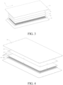
- the buffering layer 13 has a honeycomb structure. As shown in FIG. 4 , one end of the limit post 18 is fixed in a hole of the honeycomb structure.
- the first adhesive layer 15 is arranged between the first fiber-resin composite layer 11 and the metal layer 12, and the first fiber-resin composite layer 11 and the metal layer 12 are bonded together by the first adhesive layer 15.
- the second adhesive layer 16 is arranged between the metal layer 12 and the buffering layer 13, and the metal layer 12 and the buffering layer 13 are bonded together by the second adhesive layer 16.
- the buffering layer 13 is arranged with a recess 17, and the metal layer 12 is located in the recess 17. When the metal layer 12 is embedded in the recess 17, the metal layer 12 and the buffering layer 13 are initially fixed through the recess 17.
- the second adhesive layer 16 arranged between the metal layer 12 and the buffering layer 13 is melted by a heating and pressurizing means, to bond the metal layer 12 and the buffering layer 13 together. This further improves the connection strength between the metal layer 12 and the buffering layer 13 are bonded together.
- the metal layer 12 has a first dimension in a length direction of the protective plate 1
- the first fiber-resin composite layer 11 has a second dimension in the length direction of the protective plate 1
- the buffering layer 13 has a third dimension in the length direction of the protective plate 1, where the first dimension is smaller than the second dimension, and the first dimension is smaller than the third dimension
- the metal layer 12 has a fourth dimension in a width direction of the protective plate 1
- the first fiber-resin composite layer 11 has a fifth dimension in the width direction of the protective plate 1
- the buffering layer 13 has a sixth dimension in the width direction of the protective plate 1, where the fourth dimension is smaller than the fifth dimension, and the fourth dimension is smaller than the sixth dimension.
- the metal layer 12 is located between the first fiber-resin composite layer 11 and the buffering layer 13, and the length dimension and the width dimension of the metal layer 12 are defined, to avoid the corrosion of the metal layer 12.
- the length dimension of the metal layer 12 is smaller than the length dimension of the first fiber-resin composite layer 11, and the length dimension of the metal layer 12 is smaller than the length dimension of the buffering layer 13.
- the width dimension of the metal layer12 is smaller than the width dimension of the first fiber-resin composite layer 11, and the width dimension of the metal layer 12 is smaller than the width dimension of the buffering layer 13. That is, the surface area of the metal layer 12 is smaller than the surface area of the first fiber-resin composite layer 11, and the surface area of the metal layer 12 is smaller than the surface area of the buffering layer 13.
- the surface area of the metal layer 12 is smaller than the surface area of the first fiber-resin composite layer 11 and the surface area of the metal layer 12 is smaller than the surface area of the buffering layer 13,
- a portion of the first fiber-resin composite layer 11 is laminated with the metal layer 12, and the other portion of the first fiber-resin composite layer 11 is laminated with the buffering layer 13, so that the metal layer 12 is located between the first fiber-resin composite layer 11 and the buffering layer 13, to avoid the surface corrosion of the metal layer 12.
- the second fiber-resin composite layer 14 has a seventh dimension in the length direction of the protective plate 1, and the seventh dimension is equal to the second dimension; and/or the second fiber-resin composite layer 14 having an eighth dimension in the width direction of the protective plate 1, and the fifth dimension is equal to the eighth dimension.
- the length dimension of the buffering layer 13 is smaller than the length dimension of the first fiber-resin composite layer 11
- the width dimension of the buffering layer 13 is smaller than the width dimension of the first fiber-resin composite layer 11
- the length dimension of the second fiber-resin composite layer 14 is equal to the length dimension of the first fiber-resin composite layer 11
- the width dimension of the second fiber-resin composite layer 14 is equal to the width dimension of the first fiber-resin composite layer 11
- the second dimension is greater than or equal to the third dimension; and/or the fifth dimension is greater than or equal to the sixth dimension.
- the relationship between the length dimension of the first fiber-resin composite layer 11 and the length dimension of the buffering layer 13 is defined, and the relationship between the width dimension of the first fiber-resin composite layer 11 and the width dimension of the buffering layer 13 is defined, so that each surface of the metal layer 12 will not be exposed to the outside and each surface of the metal layer 12 will not be corroded.
- the length dimension of the first fiber-resin composite layer 11 is equal to the length dimension of the buffering layer 13
- the width dimension of the first fiber-resin composite layer 11 is equal to the width dimension of the buffering layer 13.
- a portion of the first fiber-resin composite layer 11 will be laminated with the metal layer 12, and the other portion of the first fiber-resin composite layer 11 will be laminated with the buffering layer 13.
- the length dimension of the first fiber-resin composite layer 11 is greater than the length dimension of the buffering layer 13
- the width dimension of the first fiber-resin composite layer 11 is greater than the width dimension of the buffering layer 13
- the length dimension of the first fiber-resin composite layer 11 is equal to the length dimension of the second fiber-resin composite layer 14
- the width dimension of the first fiber-resin composite layer 11 is equal to the width dimension of the second fiber-resin composite layer 14.
- a portion of the first fiber-resin composite layer 11 will be laminated with the metal layer 12, and the other portion of the first fiber-resin composite layer 11 will be laminated with the second fiber-resin composite layer 14.
- the protective plate 1 has a length dimension of Lmm. In the length direction of the protective plate 1, a first distance exists between an edge of the metal layer 12 and an edge of the first fiber-resin composite layer 11, and the dimension of the first distance is L*(3% to 8%)mm.
- a second distance exists between the edge of the metal layer 12 and an edge of the buffering layer 13, and the dimension of the second distance is L*(3% to 8%)mm.
- the protective plate 1 has a width dimension of Wmm. In the width direction of the protective plate 1, a third distance exists between an edge of the metal layer 12 and an edge of the first fiber-resin composite layer 11, and the dimension of the third distance is W*(2% to 12%)mm.
- a fourth distance exists between the edge of the metal layer 12 and an edge of the buffering layer 13, and the dimension of the fourth distance is W*(2% to 12%)mm.
- the metal layer 12 has a first edge and a second edge
- the first fiber-resin composite layer 11 has a third edge and a fourth edge.
- the first edge and the third edge are located at the same side
- the second edge and the fourth edge are located at the same side.
- a first distance exists between the first edge of the metal layer 12 and the third edge of the first fiber-resin composite layer 11, and the dimension of the first distance is L*(3% to 8%)mm.
- a first distance exists between the second edge of the metal layer 12 and the fourth edge of the first fiber-resin composite layer 11, and the dimension of the first distance is L*(3% to 8%)mm.
- the buffering layer 13 has a fifth edge and a sixth edge.
- the first edge and the fifth edge are located at the same side, and the second edge and the sixth edge are located at the same side.
- a second distance exists between the first edge and the fifth, and a second distance exists between the second edge and the sixth edge.
- the length dimension of the metal layer 12 is smaller than the length dimension of the first fiber-resin composite layer 11, and the length dimension of the metal layer 12 is smaller than the length dimension of the buffering layer 13.
- a first distance is defined to exist between an edge of the metal layer 12 and an edge of the first fiber-resin composite layer 11, and the dimension of the first distance is L*(3% to 8%)mm.
- a second distance is defined to exist between the edge of the metal layer 12 and an edge of the buffering layer 13, and the dimension of the second distance is L*(3% to 8%)mm.
- the metal layer 12 is located between the first fiber-resin composite layer 11 and the buffering layer 13, to avoid the corrosion of the surface of the metal layer 12 arranged along the length direction of the protective plate 1. Furthermore, since the length dimension of the metal layer 12 is smaller than the length dimension of the first fiber-resin composite layer 11, and the length dimension of the metal layer 12 is smaller than the length dimension of the buffering layer 13, the metal layer 12 is not arranged in an edge region in the length direction of the protective plate 1. In this embodiment, by defining the first distance and the second distance within this range, the structural strength of the edge region of the protective plate 1 is enhanced.
- the metal layer 12 has a seventh edge and an eighth edge
- the first fiber-resin composite layer 11 has a ninth edge and a tenth edge.
- the seventh edge and the ninth edge are located at the same side
- the eighth edge and the tenth edge are located at the same side.
- a third distance exists between the seventh edge and the ninth edge
- a third edge exists between the eighth edge and the tenth edge.
- the buffering layer 13 has an eleventh edge and a twelfth edge.
- the seventh edge and the eleventh edge are located at the same side, and the eighth edge and the twelfth edge are located at the same side.
- the width dimension of the metal lay er 12 is smaller than the width dimension of the first fiber-resin composite layer 11, and the width dimension of the metal layer 12 is smaller than the width dimension of the buffering layer 13.
- a third distance is defined to exist between an edge of the metal layer 12 and an edge of the first fiber-resin composite layer 11, and the dimension of the third distance is W*(2% to 12%)mm.
- a fourth distance is defined to exist between the edge of the metal layer 12 and an edge of the buffering layer 13, and the dimension of the fourth distance is W*(2% to 12%)mm.
- the metal layer 12 is located between the first fiber-resin composite layer 11 and the buffering layer 13, to avoid the corrosion of the surface of the metal layer 12 arranged along the width direction of the protective plate 1. Moreover, the metal layer 12 is not arranged in an edge region in the width direction of the protective plate 1. In this embodiment, by defining the third distance and the fourth distance within this range, the structural strength of the edge region of the protective plate 1 is enhanced.
- the dimension of the first distance can be L*(3% to 5%)mm, or L*(5% to 8%)mm
- the dimension of the second distance can be L*(3% to 5%)mm or L*(5% to 8%)mm
- the dimension of the third distance can be W*(2% to 10%)mm, or W*(3% to 12%)mm
- the dimension of the fourth distance can be W*(2% to 10%)mm, or W*(3% to 12%)mm.
- the first fiber-resin composite layer 11 includes a fiber and a resin, where the fiber is at least one of a carbon fiber, a glass fiber and an aramid fiber, and the resin is at least one of an epoxy resin, a phenolic resin, a polypropylene resin, and a nylon resin.
- the type of the fiber and the type of the resin in the first fiber-resin composite layer 11 are defined to improve the structural strength of the protective plate 1.
- the first fiber-resin composite layer 11 can be made of glass fiber and epoxy resin.
- the buffering layer 13 has a honeycomb structure 19, where a hole size of the honeycomb structure 19 ranges from 6 mm to 10 mm, and a hole wall dimension of the honeycomb structure 19 ranges from 0.3 mm to 0.8 mm; or the buffering layer 13 has a foam structure.
- the honeycomb structure 19 in the buffering layer is defined, particularly, the spatial size and the hole wall dimension of the honeycomb structure are defined, so that the buffering layer 13 can have a better buffering and energy absorption performance.
- the buffering layer 13 can be made of aluminum, and a honeycomb structure is formed on the aluminum plate; or, the buffering layer 13 can be made of polypropylene, and a honeycomb structure is formed on the polypropylene board (PP board), to improve the impact resistance of the protective plate 1, and enhance the overall rigidity of the protective plate 1.
- PP board polypropylene board
- the buffering layer 13 may have a foam structure, so that the buffering layer 13 has the function of buffering and absorbing energy.
- a battery pack 2 is provided.
- the battery pack 2 includes a tray 21 and a protective plate according to the first aspect, where the protective plate 1 is mounted on the tray 21.
- a battery pack 2 is provided.
- the battery pack 2 includes the protective plate 1 of the present disclosure.
- the protective plate 1 is mounted on the tray 21 of the battery pack 2.
- the protective plate 1 serves to protect the battery module 2, so as to improve the safety performance of the battery pack 2.
- the battery pack 2 includes a sealing cover 23, a battery core 22, the tray 21 and the protective plate 1.
- the sealing cover 23 and the tray 21 define a space accommodating the battery core 22.
- the protective plate 1 is arranged outside the tray 21 and the protective plate 1 is connected to the bottom of the tray 21.
- a vehicle which includes the battery pack 2 according to the second aspect.
- a vehicle which includes the battery pack 2 and a load connected to the battery pack.
- the load includes, but is not limited to, a converter and an air-conditioner compressor etc.
Landscapes
- Chemical & Material Sciences (AREA)
- Chemical Kinetics & Catalysis (AREA)
- Electrochemistry (AREA)
- General Chemical & Material Sciences (AREA)
- Engineering & Computer Science (AREA)
- Inorganic Chemistry (AREA)
- Aviation & Aerospace Engineering (AREA)
- Materials Engineering (AREA)
- Composite Materials (AREA)
- Life Sciences & Earth Sciences (AREA)
- Sustainable Development (AREA)
- Sustainable Energy (AREA)
- Power Engineering (AREA)
- Transportation (AREA)
- Mechanical Engineering (AREA)
- Laminated Bodies (AREA)
- Battery Mounting, Suspending (AREA)
- Body Structure For Vehicles (AREA)
Abstract
Description
- The present disclosure claims priority to
Chinese Patent Application No. 202220240991.0 filed on January 28, 2022 - The present disclosure relates to the technical field of new energy, and more specifically, to a protective plate for a battery pack, a battery pack and a vehicle.
- With the increasingly high requirements for energy conservation and environmental protection, electric vehicles have made rapid development in China in recent years. Different from traditional fuel-powered vehicles, power batteries are an important component of electric vehicles. As a carrier of the power battery, the increasingly high requirements are put forward for the safety performance, mechanical performance and lightweight of a power battery housing.
- At present, the battery housing is largely made of a metal material. To reduce the weight of the vehicle body, the battery housing is generally produced with an aluminum material. However, due to the low rigidity of aluminum, when stones or other sharp objects raised by new energy vehicles during traveling hit the bottom of a battery pack, the battery housing has the risk of damage, and cannot protect the battery pack well, thus leading to the failure of the battery pack and even the hazards of fire and explosion. Therefore, a protective plate is generally arranged at the bottom of the battery pack to improve the safety performance of the battery pack.
- In related art, the protective plate is often prepared with steel, aluminum and other metal materials. However, the anti-corrosion process of protective plates made of metal materials is difficult, and the surface is easy to be corroded, so they have difficulties to meet the current requirements during use.
- An object of the present disclosure is to provide a protective plate for a battery pack, a battery pack and a vehicle.
- In a first aspect of the present disclosure, a protective plate for a battery pack is provided. The protective plate includes a first fiber-resin composite layer, a metal layer and a buffering layer laminated in sequence.
- In some embodiments, the protective plate further includes a second fiber-resin composite layer, where the second fiber-resin composite layer is arranged at a side of the buffering layer facing away from the metal layer.
- In some embodiments, a thickness of the first fiber-resin composite layer ranges from 0.3 mm to 1.0 mm, a thickness of the metal layer ranges from 0.6 mm to 1.2 mm, a thickness of the buffering layer ranges from 6 mm to 12 mm, and a thickness of the second fiber-resin composite layer ranges from 0.5 mm to 1.0 mm.
- In some embodiments, a thickness of the protective plate ranges from 7 mm to 15 mm.
- In some embodiments, a first adhesive layer is arranged between the first fiber-resin composite layer and the metal layer, where a thickness of the first adhesive layer ranges from 0.1 mm to 0.3 mm.
- In some embodiments, a second adhesive layer is arranged between the metal layer and the buffering layer, where a thickness of the second adhesive layer ranges from 0.1 mm to 0.3 mm.
- In some embodiments, a third adhesive layer is arranged between the buffering layer and the second fiber-resin composite layer, where a thickness of the third adhesive layer ranges from 0.1 mm to 0.3 mm.
- In some embodiments, the buffering layer and the metal layer are connected by a molten component. The metal layer is provided with a connecting hole, one end of the molten component is located in the connecting hole and connected to an inner wall of the connecting hole, and the other end of the molten component is connected to the buffering layer.
- In some embodiments, a recess is arranged at a side of the buffering layer and facing the metal layer, and the metal layer is located in the recess.
- In some embodiments, the metal layer has a first dimension in a length direction of the protective plate, the first fiber-resin composite layer has a second dimension in the length direction of the protective plate, and the buffering layer has a third dimension in the length direction of the protective plate, where the first dimension is smaller than the second dimension, and the first dimension is smaller than the third dimension; and/or
the metal layer has a fourth dimension in a width direction of the protective plate, the first fiber-resin composite layer has a fifth dimension in the width direction of the protective plate, and the buffering layer has a sixth dimension in the width direction of the protective plate, where the fourth dimension is smaller than the fifth dimension, and the fourth dimension is smaller than the sixth dimension. - In some embodiments, the protective plate further includes a second fiber-resin composite layer, where the second fiber-resin composite layer is arranged at a side of the buffering layer facing away from the metal layer. The second fiber-resin composite layer has a seventh dimension in the length direction of the protective plate, and the seventh dimension is equal to the second dimension; and/or the second fiber-resin composite layer has an eighth dimension in the width direction of the protective plate, and the fifth dimension is equal to the eighth dimension.
- In some embodiments, the second dimension is greater than or equal to the third dimension; and/or the fifth dimension is greater than or equal to the sixth dimension.
- In some embodiments, the protective plate has a length dimension of Lmm. In the length direction of the protective plate 1, a first distance exists between an edge of the metal layer and an edge of the first fiber-resin composite layer, and the dimension of the first distance is L*(3% to 8%)mm; and
a second distance exists between the edge of the metal layer and an edge of the buffering layer, and the dimension of the second distance is L*(3% to 8%)mm. - In some embodiments, the protective plate has a width dimension of Wmm. In the width direction of the protective plate, a third distance exists between an edge of the metal layer and an edge of the first fiber-resin composite layer, and the dimension of the third distance is W*(2% to 12%)mm; and
a fourth distance exists between the edge of the metal layer and an edge of the buffering layer, and the dimension of the fourth distance is W*(2% to 12%)mm. - In some embodiments, the first fiber-resin composite layer includes a fiber and a resin, where the fiber is at least one of a carbon fiber, a glass fiber and an aramid fiber, and the resin is at least one of an epoxy resin, a phenolic resin, a polypropylene resin, and a nylon resin.
- In some embodiments, the buffering layer has a honeycomb structure, where a hole size of the honeycomb structure ranges from 6 mm to 10 mm, and a hole wall dimension of the honeycomb structure ranges from 0.3 mm to 0.8 mm; or the buffering layer has a foam structure.
- In a second aspect of the present disclosure, a battery pack is provided. The battery pack includes a tray and a protective plate according to the first aspect, where the protective plate is mounted on the tray.
- In a third aspect of the present disclosure, a vehicle is provided, which includes the battery pack according to the second aspect.
- One technical effect of the present disclosure is that the protective plate according to the present disclosure includes the first fiber-resin composite layer, the metal layer and the buffering layer laminated in sequence, where the metal layer is located between the first fiber-resin composite layer and the buffering layer, to avoid the corrosion of the metal layer of the protective plate.
- In the protective plate of the present disclosure, the first fiber-resin composite layer and the metal layer are laminated. The plastic deformation ability of the metal layer can effectively compensate for the brittle fracture of the first fiber resin composite layer itself, thus greatly enhancing the external impact resistance of the protective plate. Moreover, the buffering layer has a good buffering and energy absorption performance. Therefore, the protective plate of the present disclosure has both impact resistance and structural rigidity, thus prolonging the service life of the protective plate.
- Other features and advantages of the present disclosure will become apparent from the following detailed description of exemplary embodiments of the present disclosure with reference to the drawings.
- Accompanying drawings that constitute a part of the specification show embodiments of the present disclosure, and are used together with the specification to explain the principle of the present disclosure.
-
FIG. 1 shows a schematic structural view of a battery pack according to the present disclosure. -
FIG. 2 shows a schematic structural view of a battery tray and a protective plate according to the present disclosure. -
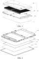
FIG. 3 shows a first schematic structural view of a protective plate according to the present disclosure. -
FIG. 4 shows a second schematic structural view of a protective plate according to the present disclosure. -
FIG. 5 shows a schematic structural view of a protective plate according to the present disclosure. -
- 1. protective plate; 11. first fiber-resin composite layer; 12. metal layer; 13. buffering layer; 14. second fiber-resin composite layer; 15. first adhesive layer; 16. second adhesive layer; 17. recess; 18. limit post; 19. honeycomb structure; 20. connecting hole;
- 2. battery pack; 21. tray; 22. battery core; 23. sealing cover.
- Various exemplary embodiments of the present disclosure are now described in detail with reference to the accompanying drawings. It is to be noted that unless otherwise specifically specified, the relative arrangement, numerical expressions, and numerical values of components and steps described in the embodiments do not limit the scope of the present disclosure.
- The following descriptions of at least one exemplary embodiment are merely illustrative, and do not constitute any limitation on the present disclosure and application or use thereof in any way.
- Technologies, and devices known to those of ordinary skill in related art may not be discussed in detail, but where appropriate, the techniques and the devices should be considered as a part of the specification.
- In all examples shown and discussed herein, any specific value should be construed to be merely exemplary, and not as limitations. Therefore, other examples of exemplary embodiments may have different values.
- It should be noted that similar reference numerals and letters indicate similar items in the following drawings. Therefore, once an item is defined in a drawing, it has no need to be discussed further in the following drawings.
- The present disclosure provides a protective plate 1 for a battery pack. As shown in
FIGs. 1 to 5 , the protective plate 1 includes a first fiber-resin composite layer 11, ametal layer 12 and abuffering layer 13 laminated in sequence. - In the embodiment of the present disclosure, the protective plate 1 includes the first fiber-
resin composite layer 11, themetal layer 12 and thebuffering layer 13, where themetal layer 12 is located between the first fiber-resin composite layer 11 and thebuffering layer 13. The first fiber-resin composite layer 11 has a composite sheet structure containing a fiber and a resin material. The first fiber-resin composite layer 11 serves as a surface material of the protective plate 1, that is, the first fiber-resin composite layer 11 is an outermost layer of the protective plate 1. The first fiber-resin composite layer 11 of the present disclosure has good corrosion resistance, and can also increase the scratch and impact resistance of the surface of themetal layer 12. The first fiber-resin composite layer 11 of the present disclosure is composed of a composite material of a fiber and a resin, which ensures the strength and rigidity of the protective plate 1. - In the embodiment of the present disclosure, the first fiber-
resin composite layer 11 and themetal layer 12 are laminated together. For example, the first fiber-resin composite layer 11 and themetal layer 12 may be directly laminated together, or the first fiber-resin composite layer 11 and themetal layer 12 may be laminated together with the aid of an intervening material. For example, the first fiber-resin composite layer 11 and themetal layer 12 are described to be laminated together by a firstadhesive layer 15 hereinafter. The firstadhesive layer 15 serves as the intervening material. In the embodiments of the present application, the plastic deformation ability of themetal layer 12 can effectively compensate for the brittle fracture of the first fiberresin composite layer 11 itself, thus greatly enhancing the external impact resistance of the protective plate 1. In addition, the first fiber-resin composite layer 11 is arranged on a surface of themetal layer 12, to avoid the phenomenon that themetal layer 12 is easily corroded. For example, themetal layer 12 can be made of steel, aluminum, and titanium alloy, etc. In some embodiments, themetal layer 12 is a steel plate. - In the embodiment of the present disclosure, the
buffering layer 13 and themetal layer 12 are laminated together. For example, thebuffering layer 13 and themetal layer 12 may be directly laminated together, or thebuffering layer 13 and themetal layer 12 may be laminated together with the aid of an intervening material. For example, thebuffering layer 13 and themetal layer 12 are described to be laminated together by a secondadhesive layer 16 hereinafter. The secondadhesive layer 16 serves as the intervening material. During use, when the protective plate 1 is impacted, since thebuffering layer 13 has a good buffering capacity, thebuffering layer 13 can absorb the force applied to the protective plate when impacted, so that the protective plate 1 has a good buffering and energy absorption performance. Particularly, the rigidity of thebuffering layer 13 is less than that of themetal layer 12. That is, when themetal layer 12 and thebuffering layer 13 are impacted by the same force, the deformation of themetal layer 12 is smaller. Therefore, themetal layer 12 has a greater structural strength, and thus can prevent the global deformation caused by undue deformation of the bottom of the protective plate 1, to improve the structural stability of the protective plate 1. Thebuffering layer 13 has a small rigidity, and can further absorb the impact energy transmitted from themetal layer 12 through its own deformation, thereby inhibiting the transmission speed of the impact energy and reducing the impact on the protective plate 1. After the protective plate 1 is impacted, the overall structural stability can be ensured, and the impact energy can be effectively absorbed, whereby the structural stability of the protective plate 1 is improved, and the service life of the protective plate 1 is prolonged. In addition, thebuffering layer 13 is arranged on another surface of themetal layer 12, to avoid the phenomenon that the surface of themetal layer 12 is easily corroded. - In an embodiment, as shown in
FIGs. 1 to 5 , the protective plate 1 further includes a second fiber-resin composite layer 14. The second fiber-resin composite layer 14 is arranged at a side of thebuffering layer 13 facing away from themetal layer 12. - In the embodiment of the present disclosure, the second fiber
resin composite layer 14 is arranged on thebuffering layer 13 and faces away from themetal layer 12. For example, the protective plate 1 includes the first fiber-resin composite layer 11, themetal layer 12, thebuffering layer 13 and the second fiber-resin composite layer 14 laminated in sequence. In the present disclosure, the second fiber-resin composite layer 14 is additionally arranged, to further enhance the structural rigidity of the protective plate 1. - In an embodiment, both the first fiber-
resin composite layer 11 and the second fiber-resin composite layer 14 include a fiber and a resin material, where the fiber material accounts for 50% to 60% by weight of the fiber-resin composite layer, and the resin material accounts for 35% to 50% by weight of the fiber-resin composite layer. In this embodiment, the fiber material and the resin material in the first fiber-resin composite layer 11 and the second fiber-resin composite layer 14 are defined, so that both the first fiber-resin composite layer 11 and the second fiber-resin composite layer 14 have the integrated characteristics of light weight, collision resistance, impact resistance and the like. - In an embodiment, as shown in
FIGs. 1 to 5 , a thickness of the first fiber-resin composite layer 11 ranges from 0.3 mm to 1.0 mm, a thickness of themetal layer 12 ranges from 0.6 mm to 1.2 mm, a thickness of thebuffering layer 13 ranges from 6 mm to 12 mm, and a thickness of the second fiber-resin composite layer 14 ranges from 0.5 mm to 1.0 mm. - In the embodiment, the thickness of the first fiber-
resin composite layer 11, themetal layer 12, thebuffering layer 13 and the second fiber-resin composite layer 14 is defined, so as to reduce the thickness of the protective plate 1 as much as possible and improve the effect of lightweighting while the structural strength, rigidity and impact resistance of the protective plate 1 are met. The protective plate 1 is applicable to thebattery pack 2, to reduce the overall height space of thebattery pack 2. - In related art, the protective plate is a metal protective plate. To prevent the corrosion of the metal protective plate, a coating is arranged on the surface of the metal protective plate. A thickness of the coating formed on the metal surface generally ranges from 1.5 mm to 3.0 mm. In this embodiment, the first fiber-
resin composite layer 11 is arranged on a surface of themetal layer 12, and a thickness of the first fiber-resin composite layer 11 ranges from 0.3 mm to 1.0 mm, so as to achieve a lightweighting design and reduce the overall thickness of the protective plate 1. For example, the thickness of the first fiber-resin composite layer 11 is 0.3 mm, 0.5 mm, 0.8 mm, or 1.0 mm. - In this embodiment, the thickness of the
metal layer 12 is defined, so as to reduce the thickness of themetal layer 12 as much as possible while the structural strength of the protective plate 1 is met. For example, the thickness of themetal layer 12 is 0.6 mm, 0.8 mm, 1 mm, or 1.2 mm. - In this embodiment, the thickness of the
buffering layer 13 is defined, so as to reduce the thickness of thebuffering layer 13 as much as possible while the buffering performance of the protective plate 1 is met. For example, the thickness of thebuffering layer 13 is 6 mm, 8 mm, 10 mm, or 12 mm. - In an embodiment, a thickness of the protective plate 1 ranges from 7 mm to 15 mm.
- In the embodiment, the overall thickness of the protective plate 1 is defined, so as to ensure the rigidity and strength of the protective plate 1 and avoid the bending of the protective plate 1 when it is hit or impacted, while the lightweighting design of the protective plate is met.
- In an embodiment, as shown in
FIGs. 3 to 5 , a firstadhesive layer 15 is arranged between the first fiber-resin composite layer 11 and themetal layer 12, and a thickness of the firstadhesive layer 15 ranges from 0.1 mm to 0.3 mm. - In an embodiment, a second
adhesive layer 16 is arranged between themetal layer 12 and thebuffering layer 13, and a thickness of the secondadhesive layer 16 ranges from 0.1 mm to 0.3 mm. - In a specific embodiment, as shown in
FIG. 3 , adjacent layers in the first fiber-resin composite layer 11, themetal layer 12 and thebuffering layer 13, are bonded by an adhesive to form the protective plate 1. For example, the firstadhesive layer 15 is arranged between the first fiber-resin composite layer 11 and themetal layer 12, and the first fiber-resin composite layer 11 and themetal layer 12 are bonded together by the firstadhesive layer 15. The secondadhesive layer 16 is arranged between themetal layer 12 and thebuffering layer 13, and themetal layer 12 and thebuffering layer 13 are bonded together by the secondadhesive layer 16. The firstadhesive layer 15 and the secondadhesive layer 16 may be the same type of adhesive layer, or the firstadhesive layer 15 and the secondadhesive layer 16 may be different types of adhesive layers. For example, the firstadhesive layer 15 is a hot melt adhesive film, which is melted by a heating and pressurizing means, to bond the first fiber-resin composite layer 11 and themetal layer 12 together. Alternatively, the firstadhesive layer 15 is a coated adhesive layer, and the first fiber-resin composite layer 11 and themetal layer 12 are directly bonded by the coated adhesive layer. The secondadhesive layer 16 is a hot melt adhesive film, which is melted by a heating and pressurizing means, to bond thebuffering layer 13 and themetal layer 12 together. Alternatively, the secondadhesive layer 16 is a coated adhesive layer, and thebuffering layer 13 and themetal layer 12 are directly bonded by the coated adhesive layer. - To avoid excessive thickness of the protective plate 1, the thicknesses of the first
adhesive layer 15 and the secondadhesive layer 16 is defined. The thicknesses of the firstadhesive layer 15 and the secondadhesive layer 16 may be the same or different. The thickness of the firstadhesive layer 15 ranges from 0.1 mm to 0.3 mm, and optionally, the thickness of the firstadhesive layer 15 ranges from 0.15 mm to 0.2 mm. The thickness of the secondadhesive layer 16 ranges from 0.1 mm to 0.3 mm, and optionally, the thickness of the secondadhesive layer 16 ranges from 0.15 mm to 0.2 mm. - In an embodiment of the present disclosure, the connection modes between the thickness of the first fiber-
resin composite layer 11, themetal layer 12 and thebuffering layer 13 are defined, so as to improve the connection reliability between adjacent layers, and avoid the splitting of the protective plate 1 during use. - In an embodiment, a third adhesive layer is arranged between the
buffering layer 13 and the second fiber-resin composite layer 14, and a thickness of the third adhesive layer ranges from 0.1 mm to 0.3 mm. - In the embodiment of the present disclosure, the
buffering layer 13 and the second fiber-resin composite layer 14 are bonded together by the third adhesive layer (not shown). For example, the third adhesive layer is a hot melt adhesive film, which is melted by a heating and pressurizing means, to bond the second fiber-resin composite layer 14 and the buffering layer together. Alternatively, the third adhesive layer is a coated adhesive layer, and the second fiber-resin composite layer 14 and thebuffering layer 13 are directly bonded by the coated adhesive layer. The thickness of the third adhesive layer ranges from 0.1 mm to 0.3 mm, and optionally, the thickness of the third adhesive layer ranges from 0.15 mm to 0.2 mm. - In an embodiment, as shown in
FIG. 4 , thebuffering layer 13 and themetal layer 12 are connected by a molten component. Themetal layer 12 is provided with a connectinghole 20, one end of the molten component is located in the connectinghole 20 and connected to an inner wall of the connectinghole 20, and the other end of the molten component is connected to thebuffering layer 13. Alternatively, - a
recess 17 is arranged at a side of thebuffering layer 13 and facing themetal layer 12, and themetal layer 12 is located in therecess 17. - In a specific embodiment, as shown in
FIG. 3 , the first fiber-resin composite layer 11 and themetal layer 12 are bonded by the firstadhesive layer 15. For example, the firstadhesive layer 15 is a hot melt adhesive film, which is melted by a heating and pressurizing means, to bond the first fiber-resin composite layer 11 and themetal layer 12 together. Alternatively, the first fiber-resin composite layer 11 and themetal layer 12 are bonded together by a coated adhesive layer. - As shown in
FIG. 4 , themetal layer 12 and thebuffering layer 13 are not bonded by an adhesive layer, but one or more molten components are arranged between themetal layer 12 and thebuffering layer 13, and themetal layer 12 and thebuffering layer 13 are connected by the molten components. For example, the molten component can be distributed along a circumferential direction of themetal layer 12 and thebuffering layer 13, or the molten component is diagonally distributed between themetal layer 12 and thebuffering layer 13, or the molten component is distributed in an array between themetal layer 12 and thebuffering layer 13. In the embodiment, alimit post 18 arranged on themetal layer 12 and thebuffering layer 13 are made in a molten state by hot pressing to form the molten component. - Particularly, the
buffering layer 13 is arranged with thelimit post 18, and themetal layer 12 is provided with a connectinghole 20 matched with thelimit post 18. Thelimit post 18 is fitted in the connectinghole 20. That is, one end of thelimit post 18 is fixed onto thebuffering layer 13, and the other end of thelimit post 18 is fixed to themetal layer 12 by the connectinghole 20. Thelimit post 18 is melted by a hot pressing process to form a molten component. Themetal layer 12 and thebuffering layer 13 are connected by the molten component (that is, molten limit post 18). One end of the molten component is fitted in the connectinghole 20, to fix the one end of the molten component to themetal layer 12, and the other end of the molten component is fixed onto thebuffering layer 13, thereby improving the connection strength between themetal layer 12 and thebuffering layer 13. For example, thelimit post 18 is a plastic post. For example, thebuffering layer 13 has a honeycomb structure. As shown inFIG. 4 , one end of thelimit post 18 is fixed in a hole of the honeycomb structure. - In another specific embodiment, as shown in
FIG. 5 , the firstadhesive layer 15 is arranged between the first fiber-resin composite layer 11 and themetal layer 12, and the first fiber-resin composite layer 11 and themetal layer 12 are bonded together by the firstadhesive layer 15. The secondadhesive layer 16 is arranged between themetal layer 12 and thebuffering layer 13, and themetal layer 12 and thebuffering layer 13 are bonded together by the secondadhesive layer 16. In the embodiment, to further improve the connection strength between themetal layer 12 and thebuffering layer 13, thebuffering layer 13 is arranged with arecess 17, and themetal layer 12 is located in therecess 17. When themetal layer 12 is embedded in therecess 17, themetal layer 12 and thebuffering layer 13 are initially fixed through therecess 17. After the initial fixing, the secondadhesive layer 16 arranged between themetal layer 12 and thebuffering layer 13 is melted by a heating and pressurizing means, to bond themetal layer 12 and thebuffering layer 13 together. This further improves the connection strength between themetal layer 12 and thebuffering layer 13 are bonded together. - In an embodiment, as shown in
FIGs. 3 to 5 , themetal layer 12 has a first dimension in a length direction of the protective plate 1, the first fiber-resin composite layer 11 has a second dimension in the length direction of the protective plate 1, and thebuffering layer 13 has a third dimension in the length direction of the protective plate 1, where the first dimension is smaller than the second dimension, and the first dimension is smaller than the third dimension; and/or
themetal layer 12 has a fourth dimension in a width direction of the protective plate 1, the first fiber-resin composite layer 11 has a fifth dimension in the width direction of the protective plate 1, and thebuffering layer 13 has a sixth dimension in the width direction of the protective plate 1, where the fourth dimension is smaller than the fifth dimension, and the fourth dimension is smaller than the sixth dimension. - In the embodiment, the
metal layer 12 is located between the first fiber-resin composite layer 11 and thebuffering layer 13, and the length dimension and the width dimension of themetal layer 12 are defined, to avoid the corrosion of themetal layer 12. - Particularly, in the length direction of the protective plate 1 (as shown in
FIG. 3 , the direction indicated by arrow a), the length dimension of themetal layer 12 is smaller than the length dimension of the first fiber-resin composite layer 11, and the length dimension of themetal layer 12 is smaller than the length dimension of thebuffering layer 13. - In the length direction of the protective plate 1 (as shown in
FIG. 3 , the direction indicated by arrow b), the width dimension of the metal layer12 is smaller than the width dimension of the first fiber-resin composite layer 11, and the width dimension of themetal layer 12 is smaller than the width dimension of thebuffering layer 13. That is, the surface area of themetal layer 12 is smaller than the surface area of the first fiber-resin composite layer 11, and the surface area of themetal layer 12 is smaller than the surface area of thebuffering layer 13. - Since the surface area of the
metal layer 12 is smaller than the surface area of the first fiber-resin composite layer 11 and the surface area of themetal layer 12 is smaller than the surface area of thebuffering layer 13, In the forming process of the protective plate 1, a portion of the first fiber-resin composite layer 11 is laminated with themetal layer 12, and the other portion of the first fiber-resin composite layer 11 is laminated with thebuffering layer 13, so that themetal layer 12 is located between the first fiber-resin composite layer 11 and thebuffering layer 13, to avoid the surface corrosion of themetal layer 12. - In an embodiment, the second fiber-
resin composite layer 14 has a seventh dimension in the length direction of the protective plate 1, and the seventh dimension is equal to the second dimension; and/or the second fiber-resin composite layer 14 having an eighth dimension in the width direction of the protective plate 1, and the fifth dimension is equal to the eighth dimension. - In the embodiment of the present disclosure, if the length dimension of the
buffering layer 13 is smaller than the length dimension of the first fiber-resin composite layer 11, the width dimension of thebuffering layer 13 is smaller than the width dimension of the first fiber-resin composite layer 11, the length dimension of the second fiber-resin composite layer 14 is equal to the length dimension of the first fiber-resin composite layer 11, and the width dimension of the second fiber-resin composite layer 14 is equal to the width dimension of the first fiber-resin composite layer 11, then a portion of the first fiber-resin composite layer 11 will be laminated with themetal layer 12, and the other portion of the first fiber-resin composite layer 11 will be laminated with the second fiber-resin composite layer 14, such that themetal layer 12 is wrapped, to avoids the corrosion of themetal layer 12. - Further, the second dimension is greater than or equal to the third dimension; and/or the fifth dimension is greater than or equal to the sixth dimension.
- In this embodiment, the relationship between the length dimension of the first fiber-
resin composite layer 11 and the length dimension of thebuffering layer 13 is defined, and the relationship between the width dimension of the first fiber-resin composite layer 11 and the width dimension of thebuffering layer 13 is defined, so that each surface of themetal layer 12 will not be exposed to the outside and each surface of themetal layer 12 will not be corroded. - When the second fiber-
resin composite layer 14 is not present, optionally, the length dimension of the first fiber-resin composite layer 11 is equal to the length dimension of thebuffering layer 13, and the width dimension of the first fiber-resin composite layer 11 is equal to the width dimension of thebuffering layer 13. In this case, a portion of the first fiber-resin composite layer 11 will be laminated with themetal layer 12, and the other portion of the first fiber-resin composite layer 11 will be laminated with thebuffering layer 13. - When the second fiber-
resin composite layer 14 is present, the length dimension of the first fiber-resin composite layer 11 is greater than the length dimension of thebuffering layer 13, the width dimension of the first fiber-resin composite layer 11 is greater than the width dimension of thebuffering layer 13, the length dimension of the first fiber-resin composite layer 11 is equal to the length dimension of the second fiber-resin composite layer 14, and the width dimension of the first fiber-resin composite layer 11 is equal to the width dimension of the second fiber-resin composite layer 14. In this case, a portion of the first fiber-resin composite layer 11 will be laminated with themetal layer 12, and the other portion of the first fiber-resin composite layer 11 will be laminated with the second fiber-resin composite layer 14. - In an embodiment, the protective plate 1 has a length dimension of Lmm. In the length direction of the protective plate 1, a first distance exists between an edge of the
metal layer 12 and an edge of the first fiber-resin composite layer 11, and the dimension of the first distance is L*(3% to 8%)mm. - A second distance exists between the edge of the
metal layer 12 and an edge of thebuffering layer 13, and the dimension of the second distance is L*(3% to 8%)mm. - The protective plate 1 has a width dimension of Wmm. In the width direction of the protective plate 1, a third distance exists between an edge of the
metal layer 12 and an edge of the first fiber-resin composite layer 11, and the dimension of the third distance is W*(2% to 12%)mm. - A fourth distance exists between the edge of the
metal layer 12 and an edge of thebuffering layer 13, and the dimension of the fourth distance is W*(2% to 12%)mm. - In the embodiment, in the length direction of the protective plate 1, the
metal layer 12 has a first edge and a second edge, and the first fiber-resin composite layer 11 has a third edge and a fourth edge. The first edge and the third edge are located at the same side, and the second edge and the fourth edge are located at the same side. A first distance exists between the first edge of themetal layer 12 and the third edge of the first fiber-resin composite layer 11, and the dimension of the first distance is L*(3% to 8%)mm. Alternatively, a first distance exists between the second edge of themetal layer 12 and the fourth edge of the first fiber-resin composite layer 11, and the dimension of the first distance is L*(3% to 8%)mm. - Similarly, in the length direction of the protective plate 1, the
buffering layer 13 has a fifth edge and a sixth edge. The first edge and the fifth edge are located at the same side, and the second edge and the sixth edge are located at the same side. A second distance exists between the first edge and the fifth, and a second distance exists between the second edge and the sixth edge. - In the embodiment, the length dimension of the
metal layer 12 is smaller than the length dimension of the first fiber-resin composite layer 11, and the length dimension of themetal layer 12 is smaller than the length dimension of thebuffering layer 13. In this embodiment, a first distance is defined to exist between an edge of themetal layer 12 and an edge of the first fiber-resin composite layer 11, and the dimension of the first distance is L*(3% to 8%)mm. A second distance is defined to exist between the edge of themetal layer 12 and an edge of thebuffering layer 13, and the dimension of the second distance is L*(3% to 8%)mm. In this way, themetal layer 12 is located between the first fiber-resin composite layer 11 and thebuffering layer 13, to avoid the corrosion of the surface of themetal layer 12 arranged along the length direction of the protective plate 1. Furthermore, since the length dimension of themetal layer 12 is smaller than the length dimension of the first fiber-resin composite layer 11, and the length dimension of themetal layer 12 is smaller than the length dimension of thebuffering layer 13, themetal layer 12 is not arranged in an edge region in the length direction of the protective plate 1. In this embodiment, by defining the first distance and the second distance within this range, the structural strength of the edge region of the protective plate 1 is enhanced. - In the embodiment, in the width direction of the protective plate 1, the
metal layer 12 has a seventh edge and an eighth edge, and the first fiber-resin composite layer 11 has a ninth edge and a tenth edge. The seventh edge and the ninth edge are located at the same side, and the eighth edge and the tenth edge are located at the same side. A third distance exists between the seventh edge and the ninth edge, and a third edge exists between the eighth edge and the tenth edge. - Similarly, in the width direction of the protective plate 1, the
buffering layer 13 has an eleventh edge and a twelfth edge. The seventh edge and the eleventh edge are located at the same side, and the eighth edge and the twelfth edge are located at the same side. A fourth distance exists between the seventh edge and the eleventh edge, and a fourth distance exists between the eighth edge and the twelfth edge. - In the embodiment, the width dimension of the metal lay er 12 is smaller than the width dimension of the first fiber-
resin composite layer 11, and the width dimension of themetal layer 12 is smaller than the width dimension of thebuffering layer 13. In this embodiment, a third distance is defined to exist between an edge of themetal layer 12 and an edge of the first fiber-resin composite layer 11, and the dimension of the third distance is W*(2% to 12%)mm. A fourth distance is defined to exist between the edge of themetal layer 12 and an edge of thebuffering layer 13, and the dimension of the fourth distance is W*(2% to 12%)mm. In this way, themetal layer 12 is located between the first fiber-resin composite layer 11 and thebuffering layer 13, to avoid the corrosion of the surface of themetal layer 12 arranged along the width direction of the protective plate 1. Moreover, themetal layer 12 is not arranged in an edge region in the width direction of the protective plate 1. In this embodiment, by defining the third distance and the fourth distance within this range, the structural strength of the edge region of the protective plate 1 is enhanced. - For example, the dimension of the first distance can be L*(3% to 5%)mm, or L*(5% to 8%)mm, the dimension of the second distance can be L*(3% to 5%)mm or L*(5% to 8%)mm; the dimension of the third distance can be W*(2% to 10%)mm, or W*(3% to 12%)mm; and the dimension of the fourth distance can be W*(2% to 10%)mm, or W*(3% to 12%)mm.
- In an embodiment, the first fiber-
resin composite layer 11 includes a fiber and a resin, where the fiber is at least one of a carbon fiber, a glass fiber and an aramid fiber, and the resin is at least one of an epoxy resin, a phenolic resin, a polypropylene resin, and a nylon resin. - In the embodiment, the type of the fiber and the type of the resin in the first fiber-
resin composite layer 11 are defined to improve the structural strength of the protective plate 1. For example, the first fiber-resin composite layer 11 can be made of glass fiber and epoxy resin. - In an embodiment, the
buffering layer 13 has ahoneycomb structure 19, where a hole size of thehoneycomb structure 19 ranges from 6 mm to 10 mm, and a hole wall dimension of thehoneycomb structure 19 ranges from 0.3 mm to 0.8 mm; or thebuffering layer 13 has a foam structure. - In this embodiment, the
honeycomb structure 19 in the buffering layer is defined, particularly, the spatial size and the hole wall dimension of the honeycomb structure are defined, so that thebuffering layer 13 can have a better buffering and energy absorption performance. - In addition, the
buffering layer 13 can be made of aluminum, and a honeycomb structure is formed on the aluminum plate; or, thebuffering layer 13 can be made of polypropylene, and a honeycomb structure is formed on the polypropylene board (PP board), to improve the impact resistance of the protective plate 1, and enhance the overall rigidity of the protective plate 1. - In an optional embodiment, the
buffering layer 13 may have a foam structure, so that thebuffering layer 13 has the function of buffering and absorbing energy. - In a second aspect of the present disclosure, a
battery pack 2 is provided. Thebattery pack 2 includes atray 21 and a protective plate according to the first aspect, where the protective plate 1 is mounted on thetray 21. - In the embodiment, a
battery pack 2 is provided. Thebattery pack 2 includes the protective plate 1 of the present disclosure. The protective plate 1 is mounted on thetray 21 of thebattery pack 2. The protective plate 1 serves to protect thebattery module 2, so as to improve the safety performance of thebattery pack 2. As shown inFIG. 1 , thebattery pack 2 includes a sealingcover 23, abattery core 22, thetray 21 and the protective plate 1. The sealingcover 23 and thetray 21 define a space accommodating thebattery core 22. The protective plate 1 is arranged outside thetray 21 and the protective plate 1 is connected to the bottom of thetray 21. - In a third aspect of the present disclosure, a vehicle is provided, which includes the
battery pack 2 according to the second aspect. - In the embodiment, a vehicle is provided, which includes the
battery pack 2 and a load connected to the battery pack. The load includes, but is not limited to, a converter and an air-conditioner compressor etc. When thebattery pack 2 is used in a vehicle, the safety of thebattery pack 2 is ensured, and the safety during the running of the vehicle is thus improved. - In the above embodiments, the differences between the various embodiments are mainly described. Where not contradictory, the different optimal features of various embodiments can be combined to form a more preferred embodiment, which will not be detailed here, considering the brevity of description.
- Although some specific embodiments of the present disclosure have been described in detail by way of examples, a person skilled in the art should understand that the foregoing examples are merely provided for description, and not intended to limit the scope of the present disclosure. A person skilled in the art should appreciate that modifications can be made to the foregoing embodiments without departing from the scope and spirit of the present disclosure. The scope of the present disclosure is defined by the appended claims.
Claims (15)
- A protective plate (1) for a battery pack (2), the protective plate (1) comprising a first fiber-resin composite layer (11), a metal layer (12), and a buffering layer (13) laminated in sequence.
- The protective plate (1) according to claim 1, the protective plate (1) further comprising a second fiber-resin composite layer (14), the second fiber-resin composite layer (14) being located at a side of the buffering layer (13) facing away from the metal layer (12).
- The protective plate (1) according to claim 2, wherein a thickness of the first fiber-resin composite layer (11) arranges from 0.3 mm to 1.0 mm, a thickness of the metal layer (12) ranges from 0.6 mm to 1.2 mm, a thickness of the buffering layer (13) ranges from 6 mm to 12 mm, and a thickness of the second fiber-resin composite layer (14) ranges from 0.5 mm to 1.0 mm.
- The protective plate (1) according to claim 1, wherein a thickness of the protective plate (1) ranges from 7 mm to 15 mm.
- The protective plate (1) according to claim 1, wherein a first adhesive layer (15) is arranged between the first fiber-resin composite layer (11) and the metal layer (12), and a thickness of the first adhesive layer (15) ranges from 0.1 mm to 0.3 mm; and/or
a second adhesive layer (16) is arranged between the metal layer (12) and the buffering layer (13), and a thickness of the second adhesive layer (16) ranges from 0.1 mm to 0.3 mm. - The protective plate (1) according to claim 2, wherein a third adhesive layer is provided between the buffering layer (13) and the second fiber-resin composite layer (14), and a thickness of the third adhesive layer ranges from 0.1 mm to 0.3 mm.
- The protective plate (1) according to claim 1, wherein the buffering layer (13) and the metal layer (12) are connected by a molten component, a connecting hole (20) is defined in the metal layer (12), one end of the molten component being located in the connecting hole (20) and connected to an inner wall of the connecting hole (20), and the other end of the molten component being connected to the buffering layer (13); or
a recess (17) is arranged at a side of the buffering layer (13) and facing the metal layer (12), and the metal layer (12) is located in the recess (17). - The protective plate (1) according to claim 1, wherein the metal layer (12) has a first dimension in a length direction of the protective plate (1), the first fiber-resin composite layer (11) has a second dimension in the length direction of the protective plate (1), the buffering layer (13) has a third dimension in the length direction of the protective plate (1), the first dimension being smaller than the second dimension, and the first dimension being smaller than the third dimension; and/or
the metal layer (12) has a fourth dimension in a width direction of the protective plate (1), the first fiber-resin composite layer (11) has a fifth dimension in the width direction of the protective plate (1), the buffering layer (13) has a sixth dimension in the width direction of the protective plate (1), the fourth dimension being smaller than the fifth dimension, and the fourth dimension being smaller than the sixth dimension. - The protective plate (1) according to claim 8, wherein the second dimension is greater than or equal to the third dimension; and/or the fifth dimension is greater than or equal to the sixth dimension.
- The protective plate (1) according to claim 8 or 9, the protective plate (1) further comprising a second fiber-resin composite layer (14), the second fiber-resin composite layer (14) being arranged at a side of the buffering layer (13) facing away from the metal layer (12), the second fiber-resin composite layer (14) having a seventh dimension in the length direction of the protective plate (1), and the seventh dimension being equal to the second dimension; and/or the second fiber-resin composite layer (14) having an eighth dimension in the width direction of the protective plate (1), and the fifth dimension being equal to the eighth dimension.
- The protective plate (1) according to claim 1, wherein the protective plate (1) has a length dimension of Lmm, in the length direction of the protective plate (1), a first distance is provided between an edge of the metal layer (12) and an edge of the first fiber-resin composite layer (11), and a dimension of the first distance is L*(3% to 8%)mm; and a second distance is provided between the edge of the metal layer (12) and an edge of the buffering layer (13), and a dimension of the second distance is L*(3% to 8%)mm; and/or
the protective plate (1) has a width dimension of Wmm, in the width direction of the protective plate (1), a third distance is provided between an edge of the metal layer (12) and an edge of the first fiber-resin composite layer (11), and a dimension of the third distance is W*(2% to 12%)mm; and a fourth distance is provided between the edge of the metal layer (12) and an edge of the buffering layer (13), and a dimension of the fourth distance is W*(2% to 12%)mm. - The protective plate (1) according to claim 1, wherein the first fiber-resin composite layer (11) comprises a fiber and a resin, the fiber being at least one of a carbon fiber, a glass fiber, and an aramid fiber, and the resin being at least one of an epoxy resin, a phenolic resin, a polypropylene resin, and a nylon resin.
- The protective plate (1) according to claim 1, wherein the buffering layer (13) has a honeycomb structure (19), a hole size of the honeycomb structure (19) ranges from 6 mm to 10 mm, and a hole wall dimension of the honeycomb structure (19) ranges from 0.3 mm to 0.8 mm; or the buffering layer (13) has a foam structure.
- A battery pack (2), the battery pack (2) comprising a tray (21) and a protective plate (1) according to any one of claims 1 to 13, the protective plate (1) being mounted on the tray (21).
- A vehicle, the vehicle comprising a battery pack (2) according to claim 14 and a load being connected to the battery pack (2).
Applications Claiming Priority (2)
| Application Number | Priority Date | Filing Date | Title |
|---|---|---|---|
| CN202220240991.0U CN216980743U (en) | 2022-01-28 | 2022-01-28 | A guard plate, battery package and vehicle for battery package |
| PCT/CN2023/071513 WO2023143040A1 (en) | 2022-01-28 | 2023-01-10 | Protective plate for battery pack, battery pack, and vehicle |
Publications (2)
| Publication Number | Publication Date |
|---|---|
| EP4447210A1 true EP4447210A1 (en) | 2024-10-16 |
| EP4447210A4 EP4447210A4 (en) | 2026-01-14 |
Family
ID=82354228
Family Applications (1)
| Application Number | Title | Priority Date | Filing Date |
|---|---|---|---|
| EP23745923.5A Pending EP4447210A4 (en) | 2022-01-28 | 2023-01-10 | PROTECTIVE PLATE FOR BATTERY PACK, BATTERY PACK AND VEHICLE |
Country Status (7)
| Country | Link |
|---|---|
| US (1) | US20240372198A1 (en) |
| EP (1) | EP4447210A4 (en) |
| JP (1) | JP7853427B2 (en) |
| KR (1) | KR20240120726A (en) |
| CN (1) | CN216980743U (en) |
| CA (1) | CA3244917A1 (en) |
| WO (1) | WO2023143040A1 (en) |
Families Citing this family (14)
| Publication number | Priority date | Publication date | Assignee | Title |
|---|---|---|---|---|
| CN216980743U (en) * | 2022-01-28 | 2022-07-15 | 比亚迪股份有限公司 | A guard plate, battery package and vehicle for battery package |
| CN118269845B (en) * | 2022-12-30 | 2025-09-16 | 比亚迪股份有限公司 | Protective plate and vehicle |
| CN118849546A (en) * | 2023-04-28 | 2024-10-29 | 比亚迪股份有限公司 | Protective panels, battery packs, and electrical equipment |
| CN116587694B (en) * | 2023-05-23 | 2026-05-08 | 宁波市阳光汽车配件有限公司 | Ablation-resistant composite protective plate and its preparation method |
| CN117698218B (en) * | 2023-11-08 | 2026-04-07 | 青岛中集创赢复合材料科技有限公司 | Battery pack guard board and preparation process thereof |
| EP4621960A1 (en) * | 2024-03-21 | 2025-09-24 | Eve Energy Co., Ltd. | Composite bottom guard, battery, and electrical device |
| DE202025101485U1 (en) * | 2024-03-25 | 2025-05-30 | Eve Energy Co., Ltd. | Floor protection plate and battery housing |
| CN221239723U (en) * | 2024-04-16 | 2024-06-28 | 宁德时代新能源科技股份有限公司 | Protective component, box, battery and electric equipment |
| CN222590916U (en) * | 2024-05-22 | 2025-03-11 | 广东金发复合材料有限公司 | Power battery protection plate, battery pack comprising same and vehicle |
| DE102024120891A1 (en) * | 2024-07-23 | 2026-01-29 | Audi Aktiengesellschaft | Support frame and battery box for mounting battery modules for a battery-electric vehicle |
| CN121460824A (en) * | 2024-07-31 | 2026-02-03 | 宁德时代新能源科技股份有限公司 | Battery device and electricity utilization device |
| CN121460825A (en) * | 2024-07-31 | 2026-02-03 | 宁德时代新能源科技股份有限公司 | Battery device and electricity utilization device |
| WO2026051232A1 (en) * | 2024-09-06 | 2026-03-12 | 惠州亿纬锂能股份有限公司 | Bottom protective plate, battery pack, and electric device |
| WO2026060924A1 (en) * | 2024-09-23 | 2026-03-26 | 惠州亿纬锂能股份有限公司 | Protective plate, battery box, battery module, and battery pack |
Family Cites Families (10)
| Publication number | Priority date | Publication date | Assignee | Title |
|---|---|---|---|---|
| JPH0768679A (en) * | 1993-09-07 | 1995-03-14 | Toyobo Co Ltd | Impact-resistant laminated structure |
| JP2006297927A (en) * | 2005-03-25 | 2006-11-02 | Toray Ind Inc | Automotive structures |
| JP2007196545A (en) * | 2006-01-27 | 2007-08-09 | Nissan Motor Co Ltd | Metal resin composite structure and manufacturing method thereof |
| CN209544447U (en) * | 2019-03-15 | 2019-10-25 | 北京新能源汽车股份有限公司蓝谷动力系统分公司 | Bottom protection plate assembly and battery pack |
| JP2021002420A (en) | 2019-06-19 | 2021-01-07 | 積水化学工業株式会社 | Battery cell housing case and battery pack |
| CN117533110A (en) | 2019-11-29 | 2024-02-09 | 比亚迪股份有限公司 | Battery pack and electric vehicle |
| CN215578819U (en) * | 2021-04-25 | 2022-01-18 | 恒大新能源技术(深圳)有限公司 | Battery protection plate, battery box body, battery pack and vehicle |
| CN215451600U (en) | 2021-06-08 | 2022-01-07 | 比亚迪股份有限公司 | Battery package end backplate and vehicle |
| CN113500830B (en) | 2021-07-09 | 2022-12-20 | 广东汇天航空航天科技有限公司 | Battery boxes and composite materials for battery boxes |
| CN216980743U (en) * | 2022-01-28 | 2022-07-15 | 比亚迪股份有限公司 | A guard plate, battery package and vehicle for battery package |
-
2022
- 2022-01-28 CN CN202220240991.0U patent/CN216980743U/en active Active
-
2023
- 2023-01-10 CA CA3244917A patent/CA3244917A1/en active Pending
- 2023-01-10 JP JP2024539685A patent/JP7853427B2/en active Active
- 2023-01-10 EP EP23745923.5A patent/EP4447210A4/en active Pending
- 2023-01-10 WO PCT/CN2023/071513 patent/WO2023143040A1/en not_active Ceased
- 2023-01-10 KR KR1020247021719A patent/KR20240120726A/en active Pending
-
2024
- 2024-07-19 US US18/777,729 patent/US20240372198A1/en active Pending
Also Published As
| Publication number | Publication date |
|---|---|
| JP7853427B2 (en) | 2026-04-28 |
| WO2023143040A1 (en) | 2023-08-03 |
| CN216980743U (en) | 2022-07-15 |
| EP4447210A4 (en) | 2026-01-14 |
| KR20240120726A (en) | 2024-08-07 |
| JP2025501970A (en) | 2025-01-24 |
| CA3244917A1 (en) | 2025-06-13 |
| US20240372198A1 (en) | 2024-11-07 |
Similar Documents
| Publication | Publication Date | Title |
|---|---|---|
| US20240372198A1 (en) | Protective plate for battery pack, battery pack, and vehicle | |
| CN215451600U (en) | Battery package end backplate and vehicle | |
| US11152660B2 (en) | Device for accommodating at least one energy module for a motor vehicle | |
| US8276975B2 (en) | FRP panel for automobile | |
| US20230014338A1 (en) | Electrical storage battery and vehicle | |
| CN213483866U (en) | Battery pack and vehicle | |
| CN219873805U (en) | Lower inner shell, lower shell, battery box and battery pack of battery pack | |
| US12459575B2 (en) | Vehicle body rear structure | |
| CN118849546A (en) | Protective panels, battery packs, and electrical equipment | |
| CN214688995U (en) | Battery packs and vehicles | |
| CN120322371A (en) | Underbody protection for a motor vehicle, motor vehicle having an underbody protection and method for producing an underbody protection | |
| JP2024526543A (en) | Protective member for battery structure of electric vehicle | |
| KR102171586B1 (en) | Method for The Battery Lower Case | |
| JP2011198472A (en) | Battery pack | |
| CN217387353U (en) | A fender structure and a vehicle having the same | |
| CN212400928U (en) | Upper guard for electric vehicle battery | |
| CN209298215U (en) | A kind of battery pack upper housing and the electric car with the upper housing | |
| CN223309114U (en) | Bottom plate, battery pack and power consumption device | |
| EP4624151A1 (en) | Bottom guard plate and battery box | |
| CN213278272U (en) | Battery package frame fixing device | |
| CN113386589A (en) | Upper guard for electric vehicle battery | |
| CN224191197U (en) | Battery pack | |
| CN215644720U (en) | Battery cell supporting structure of battery module, battery module and battery pack | |
| CN216928806U (en) | Battery pack box and battery pack | |
| CN223309115U (en) | Bottom plate, battery pack and power consumption device |
Legal Events
| Date | Code | Title | Description |
|---|---|---|---|
| STAA | Information on the status of an ep patent application or granted ep patent |
Free format text: STATUS: THE INTERNATIONAL PUBLICATION HAS BEEN MADE |
|
| PUAI | Public reference made under article 153(3) epc to a published international application that has entered the european phase |
Free format text: ORIGINAL CODE: 0009012 |
|
| STAA | Information on the status of an ep patent application or granted ep patent |
Free format text: STATUS: REQUEST FOR EXAMINATION WAS MADE |
|
| 17P | Request for examination filed |
Effective date: 20240628 |
|
| AK | Designated contracting states |
Kind code of ref document: A1 Designated state(s): AL AT BE BG CH CY CZ DE DK EE ES FI FR GB GR HR HU IE IS IT LI LT LU LV MC ME MK MT NL NO PL PT RO RS SE SI SK SM TR |
|
| DAV | Request for validation of the european patent (deleted) | ||
| DAX | Request for extension of the european patent (deleted) | ||
| A4 | Supplementary search report drawn up and despatched |
Effective date: 20251212 |
|
| RIC1 | Information provided on ipc code assigned before grant |
Ipc: H01M 50/231 20210101AFI20251208BHEP |