EP4447206A1 - Lithium secondary battery - Google Patents
Lithium secondary battery Download PDFInfo
- Publication number
- EP4447206A1 EP4447206A1 EP23857653.2A EP23857653A EP4447206A1 EP 4447206 A1 EP4447206 A1 EP 4447206A1 EP 23857653 A EP23857653 A EP 23857653A EP 4447206 A1 EP4447206 A1 EP 4447206A1
- Authority
- EP
- European Patent Office
- Prior art keywords
- electrode
- electrode terminal
- secondary battery
- lithium secondary
- cap
- Prior art date
- Legal status (The legal status is an assumption and is not a legal conclusion. Google has not performed a legal analysis and makes no representation as to the accuracy of the status listed.)
- Pending
Links
Images



Classifications
-
- H—ELECTRICITY
- H01—ELECTRIC ELEMENTS
- H01M—PROCESSES OR MEANS, e.g. BATTERIES, FOR THE DIRECT CONVERSION OF CHEMICAL ENERGY INTO ELECTRICAL ENERGY
- H01M50/00—Constructional details or processes of manufacture of the non-active parts of electrochemical cells other than fuel cells, e.g. hybrid cells
- H01M50/50—Current conducting connections for cells or batteries
- H01M50/543—Terminals
- H01M50/547—Terminals characterised by the disposition of the terminals on the cells
- H01M50/548—Terminals characterised by the disposition of the terminals on the cells on opposite sides of the cell
-
- H—ELECTRICITY
- H01—ELECTRIC ELEMENTS
- H01M—PROCESSES OR MEANS, e.g. BATTERIES, FOR THE DIRECT CONVERSION OF CHEMICAL ENERGY INTO ELECTRICAL ENERGY
- H01M10/00—Secondary cells; Manufacture thereof
- H01M10/05—Accumulators with non-aqueous electrolyte
- H01M10/052—Li-accumulators
-
- H—ELECTRICITY
- H01—ELECTRIC ELEMENTS
- H01M—PROCESSES OR MEANS, e.g. BATTERIES, FOR THE DIRECT CONVERSION OF CHEMICAL ENERGY INTO ELECTRICAL ENERGY
- H01M10/00—Secondary cells; Manufacture thereof
- H01M10/05—Accumulators with non-aqueous electrolyte
- H01M10/052—Li-accumulators
- H01M10/0525—Rocking-chair batteries, i.e. batteries with lithium insertion or intercalation in both electrodes; Lithium-ion batteries
-
- H—ELECTRICITY
- H01—ELECTRIC ELEMENTS
- H01M—PROCESSES OR MEANS, e.g. BATTERIES, FOR THE DIRECT CONVERSION OF CHEMICAL ENERGY INTO ELECTRICAL ENERGY
- H01M10/00—Secondary cells; Manufacture thereof
- H01M10/05—Accumulators with non-aqueous electrolyte
- H01M10/058—Construction or manufacture
- H01M10/0585—Construction or manufacture of accumulators having only flat construction elements, i.e. flat positive electrodes, flat negative electrodes and flat separators
-
- H—ELECTRICITY
- H01—ELECTRIC ELEMENTS
- H01M—PROCESSES OR MEANS, e.g. BATTERIES, FOR THE DIRECT CONVERSION OF CHEMICAL ENERGY INTO ELECTRICAL ENERGY
- H01M50/00—Constructional details or processes of manufacture of the non-active parts of electrochemical cells other than fuel cells, e.g. hybrid cells
- H01M50/10—Primary casings; Jackets or wrappings
- H01M50/147—Lids or covers
- H01M50/148—Lids or covers characterised by their shape
- H01M50/15—Lids or covers characterised by their shape for prismatic or rectangular cells
-
- H—ELECTRICITY
- H01—ELECTRIC ELEMENTS
- H01M—PROCESSES OR MEANS, e.g. BATTERIES, FOR THE DIRECT CONVERSION OF CHEMICAL ENERGY INTO ELECTRICAL ENERGY
- H01M50/00—Constructional details or processes of manufacture of the non-active parts of electrochemical cells other than fuel cells, e.g. hybrid cells
- H01M50/10—Primary casings; Jackets or wrappings
- H01M50/147—Lids or covers
- H01M50/148—Lids or covers characterised by their shape
- H01M50/154—Lid or cover comprising an axial bore for receiving a central current collector
-
- H—ELECTRICITY
- H01—ELECTRIC ELEMENTS
- H01M—PROCESSES OR MEANS, e.g. BATTERIES, FOR THE DIRECT CONVERSION OF CHEMICAL ENERGY INTO ELECTRICAL ENERGY
- H01M50/00—Constructional details or processes of manufacture of the non-active parts of electrochemical cells other than fuel cells, e.g. hybrid cells
- H01M50/10—Primary casings; Jackets or wrappings
- H01M50/172—Arrangements of electric connectors penetrating the casing
- H01M50/174—Arrangements of electric connectors penetrating the casing adapted for the shape of the cells
- H01M50/176—Arrangements of electric connectors penetrating the casing adapted for the shape of the cells for prismatic or rectangular cells
-
- H—ELECTRICITY
- H01—ELECTRIC ELEMENTS
- H01M—PROCESSES OR MEANS, e.g. BATTERIES, FOR THE DIRECT CONVERSION OF CHEMICAL ENERGY INTO ELECTRICAL ENERGY
- H01M50/00—Constructional details or processes of manufacture of the non-active parts of electrochemical cells other than fuel cells, e.g. hybrid cells
- H01M50/10—Primary casings; Jackets or wrappings
- H01M50/183—Sealing members
- H01M50/186—Sealing members characterised by the disposition of the sealing members
-
- H—ELECTRICITY
- H01—ELECTRIC ELEMENTS
- H01M—PROCESSES OR MEANS, e.g. BATTERIES, FOR THE DIRECT CONVERSION OF CHEMICAL ENERGY INTO ELECTRICAL ENERGY
- H01M50/00—Constructional details or processes of manufacture of the non-active parts of electrochemical cells other than fuel cells, e.g. hybrid cells
- H01M50/40—Separators; Membranes; Diaphragms; Spacing elements inside cells
- H01M50/46—Separators, membranes or diaphragms characterised by their combination with electrodes
-
- H—ELECTRICITY
- H01—ELECTRIC ELEMENTS
- H01M—PROCESSES OR MEANS, e.g. BATTERIES, FOR THE DIRECT CONVERSION OF CHEMICAL ENERGY INTO ELECTRICAL ENERGY
- H01M50/00—Constructional details or processes of manufacture of the non-active parts of electrochemical cells other than fuel cells, e.g. hybrid cells
- H01M50/50—Current conducting connections for cells or batteries
- H01M50/531—Electrode connections inside a battery casing
- H01M50/54—Connection of several leads or tabs of plate-like electrode stacks, e.g. electrode pole straps or bridges
-
- H—ELECTRICITY
- H01—ELECTRIC ELEMENTS
- H01M—PROCESSES OR MEANS, e.g. BATTERIES, FOR THE DIRECT CONVERSION OF CHEMICAL ENERGY INTO ELECTRICAL ENERGY
- H01M50/00—Constructional details or processes of manufacture of the non-active parts of electrochemical cells other than fuel cells, e.g. hybrid cells
- H01M50/50—Current conducting connections for cells or batteries
- H01M50/543—Terminals
- H01M50/547—Terminals characterised by the disposition of the terminals on the cells
-
- H—ELECTRICITY
- H01—ELECTRIC ELEMENTS
- H01M—PROCESSES OR MEANS, e.g. BATTERIES, FOR THE DIRECT CONVERSION OF CHEMICAL ENERGY INTO ELECTRICAL ENERGY
- H01M50/00—Constructional details or processes of manufacture of the non-active parts of electrochemical cells other than fuel cells, e.g. hybrid cells
- H01M50/50—Current conducting connections for cells or batteries
- H01M50/543—Terminals
- H01M50/547—Terminals characterised by the disposition of the terminals on the cells
- H01M50/55—Terminals characterised by the disposition of the terminals on the cells on the same side of the cell
-
- H—ELECTRICITY
- H01—ELECTRIC ELEMENTS
- H01M—PROCESSES OR MEANS, e.g. BATTERIES, FOR THE DIRECT CONVERSION OF CHEMICAL ENERGY INTO ELECTRICAL ENERGY
- H01M50/00—Constructional details or processes of manufacture of the non-active parts of electrochemical cells other than fuel cells, e.g. hybrid cells
- H01M50/50—Current conducting connections for cells or batteries
- H01M50/543—Terminals
- H01M50/552—Terminals characterised by their shape
- H01M50/553—Terminals adapted for prismatic, pouch or rectangular cells
-
- H—ELECTRICITY
- H01—ELECTRIC ELEMENTS
- H01M—PROCESSES OR MEANS, e.g. BATTERIES, FOR THE DIRECT CONVERSION OF CHEMICAL ENERGY INTO ELECTRICAL ENERGY
- H01M2220/00—Batteries for particular applications
- H01M2220/20—Batteries in motive systems, e.g. vehicle, ship, plane
-
- Y—GENERAL TAGGING OF NEW TECHNOLOGICAL DEVELOPMENTS; GENERAL TAGGING OF CROSS-SECTIONAL TECHNOLOGIES SPANNING OVER SEVERAL SECTIONS OF THE IPC; TECHNICAL SUBJECTS COVERED BY FORMER USPC CROSS-REFERENCE ART COLLECTIONS [XRACs] AND DIGESTS
- Y02—TECHNOLOGIES OR APPLICATIONS FOR MITIGATION OR ADAPTATION AGAINST CLIMATE CHANGE
- Y02E—REDUCTION OF GREENHOUSE GAS [GHG] EMISSIONS, RELATED TO ENERGY GENERATION, TRANSMISSION OR DISTRIBUTION
- Y02E60/00—Enabling technologies; Technologies with a potential or indirect contribution to GHG emissions mitigation
- Y02E60/10—Energy storage using batteries
-
- Y—GENERAL TAGGING OF NEW TECHNOLOGICAL DEVELOPMENTS; GENERAL TAGGING OF CROSS-SECTIONAL TECHNOLOGIES SPANNING OVER SEVERAL SECTIONS OF THE IPC; TECHNICAL SUBJECTS COVERED BY FORMER USPC CROSS-REFERENCE ART COLLECTIONS [XRACs] AND DIGESTS
- Y02—TECHNOLOGIES OR APPLICATIONS FOR MITIGATION OR ADAPTATION AGAINST CLIMATE CHANGE
- Y02P—CLIMATE CHANGE MITIGATION TECHNOLOGIES IN THE PRODUCTION OR PROCESSING OF GOODS
- Y02P70/00—Climate change mitigation technologies in the production process for final industrial or consumer products
- Y02P70/50—Manufacturing or production processes characterised by the final manufactured product
Definitions
- the present invention relates to a lithium secondary battery, and more particularly to a prismatic lithium secondary battery with low internal resistance and high design freedom when configuring a battery module construction.
- these battery cells are manufactured in a variety of shapes, including cylindrical, prismatic, and pouch-type.
- cylindrical and prismatic cells are commonly used in medium to large-sized modules that require high power, as they are relatively easy to achieve high capacity.
- the battery cell is configured by accommodating an electrode assembly formed by interposing a separator, which is an insulator, between a positive electrode and a negative electrode and an electrolyte together in a case, and by installing a cap plate on the case.
- the electrode assembly is connected with a positive electrode terminal and a negative electrode terminal, and these terminals are formed by protruding outwardly through the cap plate.
- FIG. 1 is a perspective view of a conventional cylindrical and prismatic battery cell structure, wherein the electrode assembly applied to the cell is in the form of a jellyroll. Due to structural limitations, the electrode assembly in the form of a jellyroll can only have one positive electrode lead and one negative electrode lead protruding to the outside, so the resistance generated inside the battery is greatly limited compared to the case where a plurality of electrode leads are introduced.
- An object of the present invention is to provide a secondary battery capable of reducing the internal resistance of a battery while allowing for easy positioning of electrode terminals, thereby providing a high degree of design freedom in the configuration of a battery module.
- the present invention provides a lithium secondary battery comprising:
- the upper cap may include the first electrode terminal and the second electrode terminal on the upper part surface; and include the first electrode terminal and the second electrode terminal on the A-side and the C-side of the cap side part, respectively, or may only include the second electrode terminal on the A-side or the C-side of the cap side part.
- the upper cap may include the first electrode terminal the upper surface part; and include the first electrode terminal and the second electrode terminal on the A-side and the C-side of the cap side part, respectively, or may only include the second electrode terminal on the A-side or the C-side of the cap side part.
- a total number of first electrode terminal and second electrode terminal may be three or more.
- the main body may be provided with a lead penetrating part on the upper part to expose a first electrode lead and a second electrode lead on the first side and the third side, respectively.
- the lead penetrating part may be formed from a point where the height is 1/2 to 4/5 to the upper end, relative to the lower end part of the first side and third side.
- a sealing part disposed between the outer periphery of the first electrode lead and the second electrode lead and the inner periphery of the lead penetrating part may be included.
- the A-side and the C-side of the upper cap may have a structure covering a lead penetrating part of the main body.
- the electrode assembly has a stacked structure with a plurality of first electrodes and a plurality of second electrodes alternately stacked and a separator interposed between the first electrodes and the second electrodes, and the first electrode and the second electrode may include at least one first electrode lead and one second electrode lead, respectively, on one side and an adjacent side located at the open upper end part of the main body when the inserted into the case.
- the first electrode and the second electrode include an electrode active layer, respectively, wherein the electrode active layer may be located at a height lower than the lead penetrating part when inserted into the main body.
- the lithium secondary battery according to the present invention has the advantage of including a stacked electrode assembly including a plurality of electrode leads, resulting in a significantly lower resistance inside the battery.
- the lithium secondary battery has the advantage that one or more first electrode terminals and second electrode terminals may be selectively disposed on an upper surface part of the upper cap and/or on a cap side part, respectively, thereby facilitating a position change of the electrode terminals, and providing a high degree of design freedom when configuring a battery module.
- the present invention provides a lithium secondary battery comprising
- a lithium secondary battery according to the present invention has a structure including an electrode assembly including a first electrode, a second electrode, and a separator, and a case in which an electrolyte is accommodated, wherein a plurality of at least one of the first electrode lead and the second electrode lead is introduced into the stacked electrode assembly to further reduce the resistance inside the battery.
- a plurality of electrode leads may be electrically connected with electrode terminals provided on an upper surface part or a side part of the battery, thereby facilitating a position change of the electrode terminals, which has the advantage of providing a high degree of design freedom in configuring the battery module.
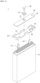
- FIG. 2 is a perspective view schematically illustrating the structure of a lithium secondary battery according to the present invention, and the lithium secondary battery will be described in detail with reference to FIG. 2 .
- a lithium secondary battery 100 includes an electrode assembly 120 having a plurality of first electrodes 121 and a plurality of second electrodes 122 alternately stacked and a separator interposed therebetween.
- the first electrode 121 and second electrode 122 may be a positive electrode or a negative electrode, respectively, and in some cases may be understood as negative electrode or positive electrode, respectively.
- the positive electrode includes a positive electrode active layer including a positive electrode active material on at least one side of a positive electrode current collector including aluminum or the like, and includes a positive electrode tab extending from a non-coated part of the positive electrode current collector where the positive electrode active layer is not formed.
- the negative electrode includes a negative electrode active layer including a negative electrode active material on at least one side of a negative electrode current collector including copper or the like, and includes a negative electrode tab extending from a non-coated part of the negative electrode current collector where the negative electrode active layer is not formed.
- the plurality of positive electrode tabs and the plurality of negative electrode tabs may be welded to each other to form a positive electrode lead and a negative electrode lead, respectively.
- the separator may be made of a porous thin film, for example, a polyolefin-based resin.
- the electrode assembly 120 may include at least one or more among first electrode leads 121a, 121b and second electrode leads 122a, 122b, respectively.
- the electrode assembly 120 may have the first electrode leads 121a, 121b and the second electrode leads 122a, 122b disposed on one side located at an upper end part of the main body 110 of a case and a side adjacent thereto when inserted into the case, and there may be one or more first electrode leads 121a, 121b and second electrode leads 122a, 122b disposed this way.
- the electrode assembly 120 may include a first electrode lead 121a and a second electrode lead 122a, respectively, on one side of the electrode assembly 120 located at an upper end part of the main body 110 when inserted into the case, and may further include a first electrode lead 121b and/or a second electrode lead 122b on two adjacent sides of the one side (i.e., a first side 111a position and a third side 111c position of the main body 110).
- the electrode assembly 120 may include a first electrode lead 121a or a second electrode lead 122a on one side of the electrode assembly 120 that is positioned at an upper end part of the main body 110 when inserted into the case, and may further include a first electrode lead 121b and/or a second electrode lead 122b on two adjacent sides of the one side (i.e., a first side 111a position and a third side 111c position of the main body 110).
- the two electrode leads included in the electrode assembly 120 may be different electrode leads.
- the electrode assembly 120 when the electrode assembly 120 includes a first electrode lead 121a on one side positioned at an upper end part of the main body 110 when inserted into the case, it may include a second electrode lead 122b on a side adjacent to the one side.
- a side adjacent to the one side may include a first electrode lead 121b.
- the present invention may significantly reduce the resistance inside the battery during charge and discharge.
- the lithium secondary battery 100 includes an electrode assembly 120 and a case to store the electrode assembly 120, wherein the case may be a battery can of various shapes, such as cylindrical or prismatic, and the like. In one example, the case may be a prismatic battery can.
- the case includes a main body 110 produced by a deep-drawing method or assembled according to a blueprint, and an upper cap 130, wherein the upper cap 130 may be ultrasonically welded or laser welded in an enveloping shape to an outside of the open upper end part of the main body 110 to seal the inside.
- the main body 110 is a rectangular structure with a shape corresponding to the open upper end for accommodating the electrode assembly 120 and the electrolyte (not shown), and has a structure including a main body side part 111 formed by sequentially coupling the ends of a first side 111a to a fourth side 111d, and a lower side part (not shown) coupled to the lower end of the main body side part 111.
- the main body 110 may be provided with a lead penetrating part 112 at the upper part for exposing a first electrode lead 121b and a second electrode lead 122b on the first side 111a and third side 111c, respectively.
- the aforementioned electrode assembly 120 may have first electrode lead 121a, 121b and second electrode lead 122a, 122b located on one side located on the open upper end part and an adjacent side thereof, that is, at least one among the first side 111a and third side 111c of the main body 110, when inserted into the case to reduce resistance within the battery.
- the first side 111a and the third side 111c may be provided with a lead penetrating part 112 for exposing the first electrode lead 121b and the second electrode lead 122b, which will be located on one or more of them.
- the lead penetrating part 112 may be located at an upper part of the first side 111a and the third side 111c. More specifically, the lead penetrating part may be formed from a height above a medium height relative to the lower end part of the first side 111a and the third side 111c, such as from a point where the height is 1/2 to 4/5, more specifically from a point where the height is 3/5 to 4/5, relative to the lower end part of the first side 111a and the third side 111c, to the upper end.
- the present invention may prevent the electrolyte accommodated inside the main body 110 from leaking to the outside, while at the same time improving the disadvantage of the circuit configuration of the battery module due to the low height of the electrode terminals disposed on the side when configuring the battery module.
- the lead penetrating part 112 may include a sealing part 113.
- the lead penetrating part 112 may include a sealing part 113 that fills the space between an outer periphery of the electrode leads (e.g., the first electrode lead and/or the second electrode lead) and an inner periphery of the lead penetrating part to more firmly fix the electrode leads.
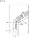
- the sealing part 113 may have an incised structure from the upper end surface of the main body 110 along the lead penetrating part 112 such that an electrode lead may be inserted in the middle, and the electrode lead may be inserted along the incision line 114.
- the sealing part 113 may be provided in a form that fills all of the inner periphery of the lead penetrating part 112 to primarily prevent leakage of the electrolyte accommodated in the main body 110 when the electrode assembly 120 is inserted into the case, when no electrode leads are provided on one side corresponding to the first side 111a and the third side 111c of the main body 110, as shown in FIG. 5 .
- the sealing part 113 may be configured of an elastic material to securely fix the electrode lead without damaging it upon insertion of the electrode lead, and to seal the lead penetrating part 112 upon non-insertion of the electrode lead.
- the elastic material is not particularly limited as long as it is conventionally used in the art, but may comprise one or more resins selected from the group consisting of epoxy, silicone, silicone-based rubber, styrene-based rubber, butadiene-based rubber, polyurethane, flexible PVC, and polypropylene copolymers.
- the upper cap 130 that is coupled to the open upper end part of the main body 110 to seal the case includes a cap side part and an upper surface part.
- the cap side part 130a to 130d includes A-side 130a to D-side 130d whose ends are sequentially coupled at positions corresponding to first side 111a to fourth side 111d of the main body, and an upper surface part is coupled to the upper end of the cap side part.
- the upper cap 130 may have a structure that covers the lead penetrating part 112 of the main body 110 with the A-side 130a and C-side 130c of the upper cap located on the inner surface. As such, the upper cap 130 may be completely sealed internally by being welded with the lead penetrating part covered by the A-side 130a and C-side 130c of the upper cap.
- the upper cap 130 may be provided with first electrode terminal 161a, 161b and second electrode terminal 162a, 162b to correspond to positions of first electrode lead 121a and second electrode lead 122a of the electrode assembly 120 stored in the main body 110.
- the first electrode terminal 161a, 161b and the second electrode terminal 162a, 162b are each provided on at least one among the upper surface part and the cap side part.
- first electrode terminals 161a, 161b and second electrode terminals 162a, 162b may be provided on at least one among an upper surface part and a cap side part of the upper cap 130 on which each electrode lead is located to correspond to the locations of the first electrode leads 121a, 121b and second electrode leads 122a, 122b, respectively.
- the previously described electrode assembly 120 may have a first electrode lead 121a, 121b and a second electrode lead 122a, 122b on one side located at an open upper end part of the main body 110 and a side adjacent thereto when inserted into the case, that is, one or more among a first side 111a and a third side 111c of the main body 110, wherein first electrode terminals 161a, 161b and second electrode terminals 162a, 162b may be provided at the positions where the first electrode leads 121a, 121b and second electrode leads 122a, 122b are provided.
- the upper cap may include a first electrode terminal 161a and a second electrode terminal 162a on the upper surface, as shown in (A) and (B) of FIG. 3 , respectively, along with a first electrode terminal 161b and a second electrode terminal 162b on the A-side and C-side of the cap side part, respectively, or only along with the second electrode terminal 162b on the A-side or C-side of the cap side part.
- the upper cap basically includes a first electrode terminal 161a and a second electrode terminal 162a on the upper surface, the same may be applied to conventional lithium secondary batteries and battery circuit modules having a battery can such as prismatic and the like, and the resistance inside the battery may be reduced by having additional electrode terminals on the side surface part.
- the upper cap 130 may include a first electrode terminal 161a on the upper surface part, as shown in (C) and (D) of FIG. 3 , along with a first electrode terminal 161b and a second electrode terminal 162b on the A-side 130a and C-side 130c of the cap side part, respectively, or only along with the second electrode terminal 162b on the A-side 130a or C-side 130c of the cap side part.
- the upper cap 130 is a structure having one electrode terminal on the upper surface, and electrode terminals having a charge corresponding to the electrode terminal on the upper surface are provided on the side surface part, which has the advantage of having a higher structural freedom in the design of the battery module compared to the case of having both the first electrode terminal 161a and the second electrode terminal 162a on the upper surface.
- the upper cap 130 may include three or more first electrode terminals and second electrode terminals.
- the secondary battery including the upper cap 130 can significantly reduce the resistance inside the battery during charging and discharging, which can improve the charging and discharging performance of the secondary battery and improve the heating phenomenon caused by the internal resistance.
- the main body 110 and the upper cap 130 may be configured of a lightweight conductive metal material such as aluminum, nickel, stainless steel, or an alloy thereof.
- the main body 110 and the upper cap 130 may include a coating layer that exhibits insulating properties while sealing the electrolyte to an inside of a conductive metal material.
- the coating layer may be a coating layer including a fluorine resin or the like.
- the cap plate 140 is formed by including terminal through-holes 141a, 141b, 142a, 142b and electrolyte inlet 143, which are welded to the upper end opening of the upper cap 130 to seal the upper cap 130.
- the terminal through-holes 141a, 141b, 142a, 142b are formed at a point that is 1/3 with respect to both sides of the cap plate 140, and into said terminal through-holes 141a, 141b, 142a, 142b are inserted electrode terminals 161a, 161b, 162a, 162b insulated by gasket tubes 151a, 151b, 152a, 152b.
- the electrolyte inlet 143 is formed on one side of the cap plate 140, and is sealed by a ball (not shown). At this time, the electrolyte inlet 143 may be formed from a planar shape to a circular shape as shown in FIG. 2 . Although not shown, the electrolyte inlet 143 may be formed in an elliptical shape, a square shape, or the like, wherein the planar shape of the electrolyte inlet 143 is not limited.
- the electrolyte inlet 143 may have a vertical cross-section formed as a Y-shape. Although not shown, the electrolyte inlet 143 may have a vertical cross-sectional shape formed as an eleven-shaped shape, and the like, wherein the vertical cross-sectional shape of the electrolyte inlet 143 is not limited to this.
- the lithium secondary battery according to the present invention has the advantage of not only low resistance inside the battery by having the above-described configuration, but also high design freedom in configuring the battery module due to the ease of changing the position of the electrode terminals.
- a stacked electrode assembly was manufactured by alternately stacking the prepared positive electrodes and negative electrodes and placing the separator between them and on the outermost surface. Then, the manufactured electrode assembly was inserted into a prismatic case (width 10 cm ⁇ length 35 cm ⁇ thickness 1.6 cm) and electrolyte was injected to produce a lithium secondary battery.
- the electrolyte was a liquid electrolyte to which LiPF6 as a lithium salt was added at a concentration of 1 M in an organic solvent mixed with Ethylene Carbonate (EC) and Ethyl Methyl Carbonate (EMC) in a volume ratio of 3:7, and the height of the electrolyte was adjusted so that the active layer of each electrode was sufficiently impregnated, but lower than a lead penetrating part of the prismatic case.
- EC Ethylene Carbonate
- EMC Ethyl Methyl Carbonate
- a lithium secondary battery was manufactured in the same manner as in the examples, except that a prismatic case including a j ellyroll-type electrode assembly and having the structure of FIG. 1 was used. However, the composition (components and content) and loading amount of the active material layers respectively provided on the negative electrode and positive electrode of the electrode assembly were adjusted the same as in Example 1.
- each lithium secondary battery manufactured in the Examples and Comparative Examples was fully charged to SOC 100% under a 4.25 V voltage condition. Then, the DC resistance of each fully charged lithium secondary battery was measured, and the DC resistance deviation rate of each lithium secondary battery was calculated based on the DC resistance value of the lithium secondary battery of Comparative Example 1. The results are shown in Table 2 below.
- Table 2 Electrode terminal arrangement DC resistance deviation rate [%] Comparative Example 1 Structure in FIG. 1 - Example 1 Structure (A) in FIG. 3 -5.4 Example 2 Structure (B) in FIG. 3 -2.8 Example 3 Structure (C) in FIG. 3 -3.1 Example 4 Structure (D) in FIG. 3 -1.1 Example 5 Structure (E) in FIG. 3 -0.5
- the lithium secondary battery according to the present invention has a low internal resistance of the battery. This means that by including a stacked electrode assembly with a plurality of electrode tabs, the resistance generated during charge and discharge is lowered.
- CONVENTIONAL LITHIUM SECONDARY BATTERY 10 CASE 21: FIRST ELECTRODE LEAD 22: SECOND ELECTRODE LEAD 30: UPPER CAP 31: HOLE FOR FIRST ELECTRODE LEAD 32: HOLE FOR SECOND ELECTRODE LEAD 33: HOLE FOR ELECTROLYTE INJECTION 40: CAP PLATE 41: TERMINAL THROUGH-HOLES 42: ELECTROLYTE INLET 50: GASKET TUBE 60: ELECTRODE TERMINAL 100: LITHIUM SECONDARY BATTERY ACCORDING TO THE PRESENT INVENTION 110: MAIN BODY 111A, 111B, 111C, 111D: FIRST SIDE, SECOND SIDE, THIRD SIDE, FOURTH SIDE 112: LEAD PENETRATING PART 113: SEALING PART 114: INCISION LINE 120: ELECTRODE ASSEMBLY 121: FIRST
Landscapes
- Chemical & Material Sciences (AREA)
- Chemical Kinetics & Catalysis (AREA)
- Electrochemistry (AREA)
- General Chemical & Material Sciences (AREA)
- Engineering & Computer Science (AREA)
- Manufacturing & Machinery (AREA)
- Materials Engineering (AREA)
- Connection Of Batteries Or Terminals (AREA)
- Secondary Cells (AREA)
- Sealing Battery Cases Or Jackets (AREA)
Abstract
Description
- This application claims the benefit of priority to
Korean Patent Application No. 10-2022-0105337, filed on August 23, 2022 - The present invention relates to a lithium secondary battery, and more particularly to a prismatic lithium secondary battery with low internal resistance and high design freedom when configuring a battery module construction.
- Unlike primary batteries, which cannot be recharged, secondary batteries, which can be charged and discharged, have been actively researched, commercialized, and widely used for applications in various high-tech fields.
- In particular, in recent years, large-capacity, high-power secondary batteries using non-aqueous electrolyte solutions with high energy density have been developed, and the large-capacity, high-power secondary batteries are generally configured in the form of high-power battery modules by connecting multiple battery cells in series and parallel to be used for power storage or devices requiring large power.
- Meanwhile, these battery cells are manufactured in a variety of shapes, including cylindrical, prismatic, and pouch-type. In particular, cylindrical and prismatic cells are commonly used in medium to large-sized modules that require high power, as they are relatively easy to achieve high capacity.
- The battery cell is configured by accommodating an electrode assembly formed by interposing a separator, which is an insulator, between a positive electrode and a negative electrode and an electrolyte together in a case, and by installing a cap plate on the case. In this case, the electrode assembly is connected with a positive electrode terminal and a negative electrode terminal, and these terminals are formed by protruding outwardly through the cap plate.
- When these battery cells are electrically connected to form a medium to large-sized battery module, a separate space for connecting the terminals is required because the electrode terminals are fixed in one direction in the conventional structure. As a result, the volume of the battery module becomes large, and the circuit configuration of the battery module can only be placed on the upper part where the electrode terminals are located, resulting in inflexibility in configuring the battery module and severely limiting the user's selectivity. In addition, if the battery module is configured by placing the battery cells with the electrode terminals protruding from the upper part of the battery cells side by side, as described above, the height of the battery module is increased, which increases the height of the vehicle body when used in an electric vehicle.
- Furthermore,
FIG. 1 is a perspective view of a conventional cylindrical and prismatic battery cell structure, wherein the electrode assembly applied to the cell is in the form of a jellyroll. Due to structural limitations, the electrode assembly in the form of a jellyroll can only have one positive electrode lead and one negative electrode lead protruding to the outside, so the resistance generated inside the battery is greatly limited compared to the case where a plurality of electrode leads are introduced. - Therefore, there is a need to develop a secondary battery that can reduce the internal resistance of the battery while allowing the electrode terminals to be easily repositioned to provide greater design freedom when configuring a battery module.
-
-
Korean Patent Publication No. 10-2016-0148316 -
Korean Patent Publication No. 10-2018-0137991 - An object of the present invention is to provide a secondary battery capable of reducing the internal resistance of a battery while allowing for easy positioning of electrode terminals, thereby providing a high degree of design freedom in the configuration of a battery module.
- To address the problems described above, in an exemplary embodiment, the present invention provides a lithium secondary battery comprising:
- a stacked electrode assembly including a first electrode, a second electrode, and a separator; and a case for accommodating the electrode assembly,
- wherein the case includes:
- a main body comprising a main body side part to which an end of a first side to a fourth side is sequentially coupled, and a lower surface part coupled to a lower end of the sides; and
- an upper cap coupled to an open upper end part of the main body by including a cap side part to which an end of A-side to D-side is sequentially coupled to correspond to a first side to a fourth side of the main body, and an upper surface part coupled to an upper end of the sides,
- wherein the upper cap is provided with a first electrode terminal and a second electrode terminal, and wherein the first electrode terminal and the second electrode terminal are each provided on at least one among the upper surface part and the cap side part.
- As an example, the upper cap may include the first electrode terminal and the second electrode terminal on the upper part surface; and include the first electrode terminal and the second electrode terminal on the A-side and the C-side of the cap side part, respectively, or may only include the second electrode terminal on the A-side or the C-side of the cap side part.
- As another example, the upper cap may include the first electrode terminal the upper surface part; and include the first electrode terminal and the second electrode terminal on the A-side and the C-side of the cap side part, respectively, or may only include the second electrode terminal on the A-side or the C-side of the cap side part.
- A total number of first electrode terminal and second electrode terminal may be three or more.
- In addition, the main body may be provided with a lead penetrating part on the upper part to expose a first electrode lead and a second electrode lead on the first side and the third side, respectively.
- Moreover, the lead penetrating part may be formed from a point where the height is 1/2 to 4/5 to the upper end, relative to the lower end part of the first side and third side.
- In addition, a sealing part disposed between the outer periphery of the first electrode lead and the second electrode lead and the inner periphery of the lead penetrating part may be included.
- Moreover, the A-side and the C-side of the upper cap may have a structure covering a lead penetrating part of the main body.
- In addition, the electrode assembly has a stacked structure with a plurality of first electrodes and a plurality of second electrodes alternately stacked and a separator interposed between the first electrodes and the second electrodes, and the first electrode and the second electrode may include at least one first electrode lead and one second electrode lead, respectively, on one side and an adjacent side located at the open upper end part of the main body when the inserted into the case.
- Here, the first electrode and the second electrode include an electrode active layer, respectively, wherein the electrode active layer may be located at a height lower than the lead penetrating part when inserted into the main body.
- The lithium secondary battery according to the present invention has the advantage of including a stacked electrode assembly including a plurality of electrode leads, resulting in a significantly lower resistance inside the battery. The lithium secondary battery has the advantage that one or more first electrode terminals and second electrode terminals may be selectively disposed on an upper surface part of the upper cap and/or on a cap side part, respectively, thereby facilitating a position change of the electrode terminals, and providing a high degree of design freedom when configuring a battery module.
-
-
FIG. 1 is a perspective view of the structure of a conventional lithium secondary battery. -
FIG. 2 is a perspective view of the structure of a lithium secondary battery according to the present invention. -
FIG. 3 is a schematic illustration of a location of a first electrode terminal and a second electrode terminal provided on an upper cap. -
FIGS. 4 and5 are structural diagrams illustrating a shape of a sealing part based on the presence of electrode leads in the electrode assembly. - The present invention may have various modifications and various examples, and specific examples are illustrated in the drawings and described in detail in the description.
- However, it should be understood that the present invention is not limited to specific embodiments, and includes all modifications, equivalents or alternatives within the spirit and technical scope of the present invention.
- The terms "comprise," "include" and "have" are used herein to designate the presence of characteristics, numbers, steps, actions, components or members described in the specification or a combination thereof, and it should be understood that the possibility of the presence or addition of one or more other characteristics, numbers, steps, actions, components, members or a combination thereof is not excluded in advance.
- In addition, when a part of a layer, a film, a region or a plate is disposed "on" another part, this includes not only a case in which one part is disposed "directly on" another part, but a case in which a third part is interposed there between. In contrast, when a part of a layer, a film, a region or a plate is disposed "under" another part, this includes not only a case in which one part is disposed "directly under" another part, but a case in which a third part is interposed there between. In addition, in this application, "on" may include not only a case of disposed on an upper part but also a case of disposed on a lower part.
- Hereinafter, the present invention will be described in more detail.
- In an exemplary embodiment, the present invention provides a lithium secondary battery comprising
- a stacked electrode assembly including a first electrode, a second electrode, and a separator; and a case for accommodating the electrode assembly, wherein
- the case includes a main body comprising a main body side part to which an end of a first side to a fourth side is sequentially coupled, and a lower surface part coupled to a lower end of the sides; and an upper cap coupled to an open upper end part of the main body by including a cap side part to which an end of A-side to D-side is sequentially coupled to correspond to a first side to a fourth side of the main body, and an upper surface part coupled to an upper end of the sides,
- wherein the upper cap is provided with a first electrode terminal and a second electrode terminal, and wherein the first electrode terminal and the second electrode terminal are each provided on at least one among an upper surface part and a cap side part.
- A lithium secondary battery according to the present invention has a structure including an electrode assembly including a first electrode, a second electrode, and a separator, and a case in which an electrolyte is accommodated, wherein a plurality of at least one of the first electrode lead and the second electrode lead is introduced into the stacked electrode assembly to further reduce the resistance inside the battery. In addition, such a plurality of electrode leads may be electrically connected with electrode terminals provided on an upper surface part or a side part of the battery, thereby facilitating a position change of the electrode terminals, which has the advantage of providing a high degree of design freedom in configuring the battery module.
-
FIG. 2 is a perspective view schematically illustrating the structure of a lithium secondary battery according to the present invention, and the lithium secondary battery will be described in detail with reference toFIG. 2 . - First, a lithium
secondary battery 100 according to the present invention includes anelectrode assembly 120 having a plurality offirst electrodes 121 and a plurality ofsecond electrodes 122 alternately stacked and a separator interposed therebetween. - The
first electrode 121 andsecond electrode 122 may be a positive electrode or a negative electrode, respectively, and in some cases may be understood as negative electrode or positive electrode, respectively. Here, the positive electrode includes a positive electrode active layer including a positive electrode active material on at least one side of a positive electrode current collector including aluminum or the like, and includes a positive electrode tab extending from a non-coated part of the positive electrode current collector where the positive electrode active layer is not formed. In addition, the negative electrode includes a negative electrode active layer including a negative electrode active material on at least one side of a negative electrode current collector including copper or the like, and includes a negative electrode tab extending from a non-coated part of the negative electrode current collector where the negative electrode active layer is not formed. The plurality of positive electrode tabs and the plurality of negative electrode tabs may be welded to each other to form a positive electrode lead and a negative electrode lead, respectively. Furthermore, the separator may be made of a porous thin film, for example, a polyolefin-based resin. - In addition, the
electrode assembly 120 may include at least one or more among first electrode leads 121a, 121b and second electrode leads 122a, 122b, respectively. - Specifically, the
electrode assembly 120 may have the first electrode leads 121a, 121b and the second electrode leads 122a, 122b disposed on one side located at an upper end part of themain body 110 of a case and a side adjacent thereto when inserted into the case, and there may be one or more first electrode leads 121a, 121b and second electrode leads 122a, 122b disposed this way. - As an example, the
electrode assembly 120 may include afirst electrode lead 121a and asecond electrode lead 122a, respectively, on one side of theelectrode assembly 120 located at an upper end part of themain body 110 when inserted into the case, and may further include afirst electrode lead 121b and/or asecond electrode lead 122b on two adjacent sides of the one side (i.e., afirst side 111a position and athird side 111c position of the main body 110). - As another example, the
electrode assembly 120 may include afirst electrode lead 121a or asecond electrode lead 122a on one side of theelectrode assembly 120 that is positioned at an upper end part of themain body 110 when inserted into the case, and may further include afirst electrode lead 121b and/or asecond electrode lead 122b on two adjacent sides of the one side (i.e., afirst side 111a position and athird side 111c position of the main body 110). - Here, when the
electrode assembly 120 includes oneelectrode lead main body 110 upon being inserted into the case, and on two adjacent sides (i.e., afirst side 111a position and athird side 111c position of the main body 110), the two electrode leads included in theelectrode assembly 120 may be different electrode leads. Specifically, when theelectrode assembly 120 includes afirst electrode lead 121a on one side positioned at an upper end part of themain body 110 when inserted into the case, it may include asecond electrode lead 122b on a side adjacent to the one side. In addition, when theelectrode assembly 120 includes asecond electrode lead 122a on one side positioned at an upper end part of themain body 110 when inserted into the case, a side adjacent to the one side may include afirst electrode lead 121b. - By introducing into the
electrode assembly 120 at least one electrode lead each for thefirst electrode 121 and thesecond electrode 122, and more specifically, by introducing so that the total number of first electrode leads and second electrode leads is at least three, the present invention may significantly reduce the resistance inside the battery during charge and discharge. - In addition, the lithium
secondary battery 100 according to the present invention includes anelectrode assembly 120 and a case to store theelectrode assembly 120, wherein the case may be a battery can of various shapes, such as cylindrical or prismatic, and the like. In one example, the case may be a prismatic battery can. - Here, the case includes a
main body 110 produced by a deep-drawing method or assembled according to a blueprint, and anupper cap 130, wherein theupper cap 130 may be ultrasonically welded or laser welded in an enveloping shape to an outside of the open upper end part of themain body 110 to seal the inside. - More specifically, the
main body 110 is a rectangular structure with a shape corresponding to the open upper end for accommodating theelectrode assembly 120 and the electrolyte (not shown), and has a structure including a main body side part 111 formed by sequentially coupling the ends of afirst side 111a to afourth side 111d, and a lower side part (not shown) coupled to the lower end of the main body side part 111. - Furthermore, the
main body 110 may be provided with alead penetrating part 112 at the upper part for exposing afirst electrode lead 121b and asecond electrode lead 122b on thefirst side 111a andthird side 111c, respectively. Specifically, theaforementioned electrode assembly 120 may havefirst electrode lead second electrode lead first side 111a andthird side 111c of themain body 110, when inserted into the case to reduce resistance within the battery. In this case, thefirst side 111a and thethird side 111c may be provided with alead penetrating part 112 for exposing thefirst electrode lead 121b and thesecond electrode lead 122b, which will be located on one or more of them. - The
lead penetrating part 112 may be located at an upper part of thefirst side 111a and thethird side 111c. More specifically, the lead penetrating part may be formed from a height above a medium height relative to the lower end part of thefirst side 111a and thethird side 111c, such as from a point where the height is 1/2 to 4/5, more specifically from a point where the height is 3/5 to 4/5, relative to the lower end part of thefirst side 111a and thethird side 111c, to the upper end. - By controlling the position of the
lead penetrating part 112 as described above, the present invention may prevent the electrolyte accommodated inside themain body 110 from leaking to the outside, while at the same time improving the disadvantage of the circuit configuration of the battery module due to the low height of the electrode terminals disposed on the side when configuring the battery module. - Furthermore, the
lead penetrating part 112 may include a sealingpart 113. Specifically, as shown inFIG. 4 , when theelectrode assembly 120 is provided with electrode leads on one side corresponding to thefirst side 111a and thethird side 111c of the main body when inserted into a case, thelead penetrating part 112 may include a sealingpart 113 that fills the space between an outer periphery of the electrode leads (e.g., the first electrode lead and/or the second electrode lead) and an inner periphery of the lead penetrating part to more firmly fix the electrode leads. In this case, the sealingpart 113 may have an incised structure from the upper end surface of themain body 110 along thelead penetrating part 112 such that an electrode lead may be inserted in the middle, and the electrode lead may be inserted along theincision line 114. - Furthermore, the sealing
part 113 may be provided in a form that fills all of the inner periphery of thelead penetrating part 112 to primarily prevent leakage of the electrolyte accommodated in themain body 110 when theelectrode assembly 120 is inserted into the case, when no electrode leads are provided on one side corresponding to thefirst side 111a and thethird side 111c of themain body 110, as shown inFIG. 5 . - The sealing
part 113 may be configured of an elastic material to securely fix the electrode lead without damaging it upon insertion of the electrode lead, and to seal thelead penetrating part 112 upon non-insertion of the electrode lead. The elastic material is not particularly limited as long as it is conventionally used in the art, but may comprise one or more resins selected from the group consisting of epoxy, silicone, silicone-based rubber, styrene-based rubber, butadiene-based rubber, polyurethane, flexible PVC, and polypropylene copolymers. - Furthermore, the
upper cap 130 that is coupled to the open upper end part of themain body 110 to seal the case includes a cap side part and an upper surface part. Thecap side part 130a to 130d includes A-side 130a to D-side 130d whose ends are sequentially coupled at positions corresponding tofirst side 111a tofourth side 111d of the main body, and an upper surface part is coupled to the upper end of the cap side part. - Here, the
upper cap 130 may have a structure that covers thelead penetrating part 112 of themain body 110 with the A-side 130a and C-side 130c of the upper cap located on the inner surface. As such, theupper cap 130 may be completely sealed internally by being welded with the lead penetrating part covered by the A-side 130a and C-side 130c of the upper cap. - In addition, the
upper cap 130 may be provided withfirst electrode terminal second electrode terminal first electrode lead 121a andsecond electrode lead 122a of theelectrode assembly 120 stored in themain body 110. In this case, thefirst electrode terminal second electrode terminal - Specifically, it may include
first electrode terminals second electrode terminals electrode assembly 120 inserted into themain body 110 as shown inFIG. 3 . Here, thefirst electrode terminals second electrode terminals upper cap 130 on which each electrode lead is located to correspond to the locations of the first electrode leads 121a, 121b and second electrode leads 122a, 122b, respectively. In order to reduce resistance within the battery, the previously describedelectrode assembly 120 may have afirst electrode lead second electrode lead main body 110 and a side adjacent thereto when inserted into the case, that is, one or more among afirst side 111a and athird side 111c of themain body 110, whereinfirst electrode terminals second electrode terminals - In one example, the upper cap may include a
first electrode terminal 161a and asecond electrode terminal 162a on the upper surface, as shown in (A) and (B) ofFIG. 3 , respectively, along with afirst electrode terminal 161b and asecond electrode terminal 162b on the A-side and C-side of the cap side part, respectively, or only along with thesecond electrode terminal 162b on the A-side or C-side of the cap side part. - In this case, since the upper cap basically includes a
first electrode terminal 161a and asecond electrode terminal 162a on the upper surface, the same may be applied to conventional lithium secondary batteries and battery circuit modules having a battery can such as prismatic and the like, and the resistance inside the battery may be reduced by having additional electrode terminals on the side surface part. - As another example, the
upper cap 130 may include afirst electrode terminal 161a on the upper surface part, as shown in (C) and (D) ofFIG. 3 , along with afirst electrode terminal 161b and asecond electrode terminal 162b on the A-side 130a and C-side 130c of the cap side part, respectively, or only along with thesecond electrode terminal 162b on the A-side 130a or C-side 130c of the cap side part. - In this case, the
upper cap 130 is a structure having one electrode terminal on the upper surface, and electrode terminals having a charge corresponding to the electrode terminal on the upper surface are provided on the side surface part, which has the advantage of having a higher structural freedom in the design of the battery module compared to the case of having both thefirst electrode terminal 161a and thesecond electrode terminal 162a on the upper surface. - In addition, the
upper cap 130 may include three or more first electrode terminals and second electrode terminals. In this case, the secondary battery including theupper cap 130 can significantly reduce the resistance inside the battery during charging and discharging, which can improve the charging and discharging performance of the secondary battery and improve the heating phenomenon caused by the internal resistance. - Meanwhile, the
main body 110 and theupper cap 130 may be configured of a lightweight conductive metal material such as aluminum, nickel, stainless steel, or an alloy thereof. - In addition, the
main body 110 and theupper cap 130 may include a coating layer that exhibits insulating properties while sealing the electrolyte to an inside of a conductive metal material. Specifically, the coating layer may be a coating layer including a fluorine resin or the like. - Furthermore, the
cap plate 140 is formed by including terminal through-holes electrolyte inlet 143, which are welded to the upper end opening of theupper cap 130 to seal theupper cap 130. The terminal through-holes cap plate 140, and into said terminal through-holes electrode terminals gasket tubes electrolyte inlet 143 is formed on one side of thecap plate 140, and is sealed by a ball (not shown). At this time, theelectrolyte inlet 143 may be formed from a planar shape to a circular shape as shown inFIG. 2 . Although not shown, theelectrolyte inlet 143 may be formed in an elliptical shape, a square shape, or the like, wherein the planar shape of theelectrolyte inlet 143 is not limited. Theelectrolyte inlet 143 may have a vertical cross-section formed as a Y-shape. Although not shown, theelectrolyte inlet 143 may have a vertical cross-sectional shape formed as an eleven-shaped shape, and the like, wherein the vertical cross-sectional shape of theelectrolyte inlet 143 is not limited to this. - The lithium secondary battery according to the present invention has the advantage of not only low resistance inside the battery by having the above-described configuration, but also high design freedom in configuring the battery module due to the ease of changing the position of the electrode terminals.
- Hereinafter, the present invention will be described in more detail by way of examples and experimental examples.
- However, the following examples and experimental examples are only illustrative of the present invention, and the contents of the present invention are not limited to the following examples and experimental examples.
- First, 40 positive electrodes and negative electrodes each were prepared, and 81 porous polyethylene separators (width 9.5 cm × length 34.5 cm, average thickness about 20 µm) wider than the positive electrodes and negative electrodes were prepared as separators. A stacked electrode assembly was manufactured by alternately stacking the prepared positive electrodes and negative electrodes and placing the separator between them and on the outermost surface. Then, the manufactured electrode assembly was inserted into a prismatic case (
width 10 cm × length 35 cm × thickness 1.6 cm) and electrolyte was injected to produce a lithium secondary battery. - In this case, the electrolyte was a liquid electrolyte to which LiPF6 as a lithium salt was added at a concentration of 1 M in an organic solvent mixed with Ethylene Carbonate (EC) and Ethyl Methyl Carbonate (EMC) in a volume ratio of 3:7, and the height of the electrolyte was adjusted so that the active layer of each electrode was sufficiently impregnated, but lower than a lead penetrating part of the prismatic case.
- In addition, the prismatic cases used had the structure of
FIG. 2 , but were adjusted as shown inFIG. 3 , with the electrode terminals of each case electrically connected with the first electrode lead and the second electrode lead of the corresponding electrode assembly.[Table 1] Electrode terminal arrangement Example 1 Structure (A) in FIG. 3 Example 2 Structure (B) in FIG. 3 Example 3 Structure (C) in FIG. 3 Example 4 Structure (D) in FIG. 3 Example 5 Structure (E) in FIG. 3 - A lithium secondary battery was manufactured in the same manner as in the examples, except that a prismatic case including a j ellyroll-type electrode assembly and having the structure of
FIG. 1 was used. However, the composition (components and content) and loading amount of the active material layers respectively provided on the negative electrode and positive electrode of the electrode assembly were adjusted the same as in Example 1. - To evaluate the battery resistance of the lithium secondary battery according to the present invention, each lithium secondary battery manufactured in the Examples and Comparative Examples was fully charged to
SOC 100% under a 4.25 V voltage condition. Then, the DC resistance of each fully charged lithium secondary battery was measured, and the DC resistance deviation rate of each lithium secondary battery was calculated based on the DC resistance value of the lithium secondary battery of Comparative Example 1. The results are shown in Table 2 below.[Table 2] Electrode terminal arrangement DC resistance deviation rate [%] Comparative Example 1 Structure in FIG. 1 - Example 1 Structure (A) in FIG. 3 -5.4 Example 2 Structure (B) in FIG. 3 -2.8 Example 3 Structure (C) in FIG. 3 -3.1 Example 4 Structure (D) in FIG. 3 -1.1 Example 5 Structure (E) in FIG. 3 -0.5 - As shown in Table 2 above, it can be seen that the lithium secondary battery according to the present invention has a low internal resistance of the battery. This means that by including a stacked electrode assembly with a plurality of electrode tabs, the resistance generated during charge and discharge is lowered.
- While the foregoing has been described with reference to preferred examples of the present invention, it will be understood by those skilled in the art or having ordinary knowledge of the art that various modifications and changes can be made to the invention without departing from the field of thought and technology described in the patent claims that will follow.
- Accordingly, the technical scope of the present invention is not limited to what is described in the detailed description of the specification, but must be determined by the claims of the patent.
-
1: CONVENTIONAL LITHIUM SECONDARY BATTERY 10: CASE 21: FIRST ELECTRODE LEAD 22: SECOND ELECTRODE LEAD 30: UPPER CAP 31: HOLE FOR FIRST ELECTRODE LEAD 32: HOLE FOR SECOND ELECTRODE LEAD 33: HOLE FOR ELECTROLYTE INJECTION 40: CAP PLATE 41: TERMINAL THROUGH-HOLES 42: ELECTROLYTE INLET 50: GASKET TUBE 60: ELECTRODE TERMINAL 100: LITHIUM SECONDARY BATTERY ACCORDING TO THE PRESENT INVENTION 110: MAIN BODY 111A, 111B, 111C, 111D: FIRST SIDE, SECOND SIDE, THIRD SIDE, FOURTH SIDE 112: LEAD PENETRATING PART 113: SEALING PART 114: INCISION LINE 120: ELECTRODE ASSEMBLY 121: FIRST ELECTRODE 121a, 121b: FIRST ELECTRODE LEAD 122: SECOND ELECTRODE 122a, 122b: SECOND ELECTRODE LEAD 130: UPPER CAP 130a, 130b, 130c, 130d: A-SIDE, B-SIDE, C-SIDE, D-SIDE 131: HOLE FOR FIRST ELECTRODE LEAD 132: HOLE FOR SECOND ELECTRODE LEAD 133: HOLE FOR ELECTROLYTE INJECTION 140: CAP PLATE 141a, 141b: THROUGH-HOLE FOR FIRST ELECTRODE TERMINAL 142a, 142b: THROUGH-HOLE FOR SECOND ELECTRODE TERMINAL 143: ELECTROLYTE INLET 151a, 151b: GASKET TUBE FOR FIRST ELECTRODE TERMINAL 152a, 152b: GASKET TUBE FOR SECOND ELECTRODE TERMINAL 161a, 161b: FIRST ELECTRODE TERMINAL 162a, 162b: SECOND ELECTRODE TERMINAL
Claims (12)
- A lithium secondary battery comprising:a stacked electrode assembly comprising a first electrode, a second electrode, and a separator; and a case for accommodating the electrode assembly,wherein the case comprises:a main body comprising a main body side part forming a first side, a second side, a third side, and a fourth side of the main body, and a lower surface part disposed at lower ends of the first sides to the fourth sides; andan upper cap disposed at an open upper end part of the main body and including a cap side part forming A-side, B-side, C-side, and D-side of the upper cap corresponding to the first side to the fourth side of the main body, and an upper surface part disposed at upper ends of the A-side to D-side of the upper cap,wherein the upper cap is provided with a first electrode terminal and a second electrode terminal, andwherein the first electrode terminal and the second electrode terminal are each provided at least one among the upper surface part and the cap side part.
- The lithium secondary battery of claim 1, wherein the upper cap includes the first electrode terminal and the second electrode terminal at the upper surface part, and includes another first electrode terminal and another second electrode terminal on the A-side and the C-side of the cap side part, respectively.
- The lithium secondary battery of claim 1, wherein the upper cap includes the first electrode terminal and the second electrode terminal on the upper surface part, and only includes another second electrode terminal on the A-side or the C-side of the cap side part.
- The lithium secondary battery of claim 1, wherein the upper cap includes the first electrode terminal on the upper surface part, and
includes another first electrode terminal and the second electrode terminal on the A-side and the C-side of the cap side part, respectively. - The lithium secondary battery of claim 1, wherein the upper cap includes the first electrode terminal on the upper surface part, and
only includes the second electrode terminal on the A-side or the C-side of the cap side part. - The lithium secondary battery of claim 1, wherein a total number of first electrode terminal and second electrode terminal is three or more.
- The lithium secondary battery of claim 1, wherein the main body is provided with a lead penetrating part at a respective upper part thereof to expose a first electrode lead and a second electrode lead on the first side and the third side.
- The lithium secondary battery of claim 7, wherein the respective lead penetrating part is formed from a point where a height is 1/2 to 4/5 to the upper end, relative to the lower end part of the first side and third side.
- The lithium secondary battery of claim 7, comprising a sealing part disposed between an outer periphery of the respective first electrode lead and the second electrode lead and an inner periphery of the respective lead penetrating part.
- The lithium secondary battery of claim 7, wherein the A-side and the C-side of the upper cap covers the respective lead penetrating part of the main body.
- The lithium secondary battery of claim 1, wherein the electrode assembly has a stacked structure with a plurality of first electrodes and a plurality of second electrodes alternately stacked and a separator interposed between the first electrodes and the second electrodes, and
the first electrode and the second electrode include at least one first electrode lead and one second electrode lead, respectively, at one side and an adjacent side located at the open upper end part of the main body when inserted into the case. - The lithium secondary battery of claim 7, wherein the first electrode and the second electrode include an electrode active layer, respectively,
wherein the electrode active layer is located at a height lower than the respective lead penetrating part when inserted into the main body.
Applications Claiming Priority (2)
| Application Number | Priority Date | Filing Date | Title |
|---|---|---|---|
| KR1020220105337A KR102758557B1 (en) | 2022-08-23 | 2022-08-23 | Lithium secondary battery |
| PCT/KR2023/012230 WO2024043619A1 (en) | 2022-08-23 | 2023-08-18 | Lithium secondary battery |
Publications (2)
| Publication Number | Publication Date |
|---|---|
| EP4447206A1 true EP4447206A1 (en) | 2024-10-16 |
| EP4447206A4 EP4447206A4 (en) | 2025-12-24 |
Family
ID=90013606
Family Applications (1)
| Application Number | Title | Priority Date | Filing Date |
|---|---|---|---|
| EP23857653.2A Pending EP4447206A4 (en) | 2022-08-23 | 2023-08-18 | LITHIUM SECONDARY BATTERY |
Country Status (6)
| Country | Link |
|---|---|
| US (1) | US20250046965A1 (en) |
| EP (1) | EP4447206A4 (en) |
| JP (1) | JP7761354B2 (en) |
| KR (1) | KR102758557B1 (en) |
| CN (1) | CN118648166A (en) |
| WO (1) | WO2024043619A1 (en) |
Family Cites Families (12)
| Publication number | Priority date | Publication date | Assignee | Title |
|---|---|---|---|---|
| CN100336245C (en) | 1998-01-14 | 2007-09-05 | 杨泰和 | Low internal resistance confluence structure of storage and discharge device |
| JP2002289155A (en) * | 2001-03-23 | 2002-10-04 | Mitsubishi Heavy Ind Ltd | Secondary battery and method of manufacturing the same |
| KR100754918B1 (en) | 2006-04-20 | 2007-09-03 | 현대에너셀 주식회사 | Side terminal type battery |
| KR100776766B1 (en) * | 2006-05-17 | 2007-11-16 | 현대에너셀 주식회사 | Battery having upper terminal |
| US9263762B2 (en) | 2013-11-22 | 2016-02-16 | Lanyang Energy Technology Co., Ltd. | Lithium ion batteries |
| KR102100932B1 (en) * | 2015-05-08 | 2020-04-14 | 주식회사 엘지화학 | Battery Cell Capable of Diversification of Electrical Connection Structure and Battery cell Assembly Including the Same |
| KR20160148316A (en) | 2015-06-16 | 2016-12-26 | 삼성에스디아이 주식회사 | Rechargeable battery |
| KR102074995B1 (en) * | 2015-07-27 | 2020-02-07 | 주식회사 엘지화학 | Battery Cell Having Improved Design Freedom in Positioning of Electrode Lead |
| KR20180080860A (en) * | 2017-01-05 | 2018-07-13 | 삼성에스디아이 주식회사 | Electrode assembly and rechargeable battery including the same |
| KR20180137991A (en) | 2017-06-20 | 2018-12-28 | 주식회사 엘지화학 | Secondary battery and manufactury methode for the same |
| KR102722638B1 (en) * | 2019-03-26 | 2024-10-25 | 주식회사 엘지에너지솔루션 | Battery module and method of manufacturing the same |
| KR102469872B1 (en) * | 2019-04-15 | 2022-11-23 | 에스케이온 주식회사 | Battery Module |
-
2022
- 2022-08-23 KR KR1020220105337A patent/KR102758557B1/en active Active
-
2023
- 2023-08-18 WO PCT/KR2023/012230 patent/WO2024043619A1/en not_active Ceased
- 2023-08-18 EP EP23857653.2A patent/EP4447206A4/en active Pending
- 2023-08-18 CN CN202380020201.5A patent/CN118648166A/en active Pending
- 2023-08-18 US US18/835,976 patent/US20250046965A1/en active Pending
- 2023-08-18 JP JP2024542379A patent/JP7761354B2/en active Active
Also Published As
| Publication number | Publication date |
|---|---|
| JP2025503744A (en) | 2025-02-04 |
| JP7761354B2 (en) | 2025-10-28 |
| CN118648166A (en) | 2024-09-13 |
| EP4447206A4 (en) | 2025-12-24 |
| US20250046965A1 (en) | 2025-02-06 |
| KR20240027297A (en) | 2024-03-04 |
| WO2024043619A1 (en) | 2024-02-29 |
| KR102758557B1 (en) | 2025-01-23 |
Similar Documents
| Publication | Publication Date | Title |
|---|---|---|
| US8557430B2 (en) | Rechargeable battery having current collector plate with protrusion | |
| US12476308B2 (en) | Battery case for secondary battery and pouch type secondary battery | |
| US11342636B2 (en) | Secondary battery | |
| US6387567B1 (en) | Secondary battery | |
| JP4628682B2 (en) | Battery unit and lithium secondary battery using the same | |
| US20230187795A1 (en) | Secondary battery | |
| US9172066B2 (en) | Protection circuit board, battery pack including the protection circuit board and method of fabricating the protection circuit board | |
| US20260045577A1 (en) | Pouch Type Battery Case and Pouch Type Secondary Battery | |
| KR20200091687A (en) | The Electrode Assembly And The Secondary Battery | |
| US20230216112A1 (en) | Secondary battery | |
| KR20210076770A (en) | The Case For Secondary Battery And The Pouch Type Secondary Battery | |
| KR20230086276A (en) | secondary battery | |
| US20120050946A1 (en) | Supercapacitor module | |
| EP4447206A1 (en) | Lithium secondary battery | |
| US12586846B2 (en) | Secondary battery | |
| EP4542758A1 (en) | Secondary battery and battery pack thereof | |
| US20250141048A1 (en) | Secondary battery | |
| KR102954927B1 (en) | Electrode lead, a method for manufacturing of the same, and lithium secondary battery comprising the same | |
| KR20210037460A (en) | The Battery Case For Secondary Battery And The Method For Manufacturing Thereof | |
| US20250349999A1 (en) | Integrated terminal, secondary battery including the same, and method of manufacturing the same | |
| US20260088466A1 (en) | Secondary battery | |
| US20250316747A1 (en) | Secondary battery | |
| US20250266542A1 (en) | Secondary battery and method of manufacturing a secondary battery | |
| KR20250144087A (en) | Rechargeable battery | |
| CN118899390A (en) | Electrode assembly, method for manufacturing the same, and secondary battery including the electrode assembly |
Legal Events
| Date | Code | Title | Description |
|---|---|---|---|
| STAA | Information on the status of an ep patent application or granted ep patent |
Free format text: STATUS: THE INTERNATIONAL PUBLICATION HAS BEEN MADE |
|
| PUAI | Public reference made under article 153(3) epc to a published international application that has entered the european phase |
Free format text: ORIGINAL CODE: 0009012 |
|
| STAA | Information on the status of an ep patent application or granted ep patent |
Free format text: STATUS: REQUEST FOR EXAMINATION WAS MADE |
|
| 17P | Request for examination filed |
Effective date: 20240709 |
|
| AK | Designated contracting states |
Kind code of ref document: A1 Designated state(s): AL AT BE BG CH CY CZ DE DK EE ES FI FR GB GR HR HU IE IS IT LI LT LU LV MC ME MK MT NL NO PL PT RO RS SE SI SK SM TR |
|
| DAV | Request for validation of the european patent (deleted) | ||
| DAX | Request for extension of the european patent (deleted) | ||
| A4 | Supplementary search report drawn up and despatched |
Effective date: 20251120 |
|
| RIC1 | Information provided on ipc code assigned before grant |
Ipc: H01M 50/176 20210101AFI20251114BHEP Ipc: H01M 50/547 20210101ALI20251114BHEP Ipc: H01M 50/148 20210101ALI20251114BHEP Ipc: H01M 50/46 20210101ALI20251114BHEP Ipc: H01M 50/553 20210101ALI20251114BHEP Ipc: H01M 50/186 20210101ALI20251114BHEP Ipc: H01M 10/0585 20100101ALI20251114BHEP Ipc: H01M 10/052 20100101ALI20251114BHEP Ipc: H01M 50/15 20210101ALI20251114BHEP Ipc: H01M 50/54 20210101ALI20251114BHEP Ipc: H01M 50/548 20210101ALI20251114BHEP Ipc: H01M 50/55 20210101ALI20251114BHEP |