EP4447190A1 - Method for inspecting battery module - Google Patents
Method for inspecting battery module Download PDFInfo
- Publication number
- EP4447190A1 EP4447190A1 EP23747391.3A EP23747391A EP4447190A1 EP 4447190 A1 EP4447190 A1 EP 4447190A1 EP 23747391 A EP23747391 A EP 23747391A EP 4447190 A1 EP4447190 A1 EP 4447190A1
- Authority
- EP
- European Patent Office
- Prior art keywords
- vision
- inspection process
- electrode leads
- battery module
- vision inspection
- Prior art date
- Legal status (The legal status is an assumption and is not a legal conclusion. Google has not performed a legal analysis and makes no representation as to the accuracy of the status listed.)
- Granted
Links
Images


Classifications
-
- G—PHYSICS
- G01—MEASURING; TESTING
- G01N—INVESTIGATING OR ANALYSING MATERIALS BY DETERMINING THEIR CHEMICAL OR PHYSICAL PROPERTIES
- G01N21/00—Investigating or analysing materials by the use of optical means, i.e. using sub-millimetre waves, infrared, visible or ultraviolet light
- G01N21/84—Systems specially adapted for particular applications
- G01N21/88—Investigating the presence of flaws or contamination
- G01N21/8806—Specially adapted optical and illumination features
-
- G—PHYSICS
- G01—MEASURING; TESTING
- G01N—INVESTIGATING OR ANALYSING MATERIALS BY DETERMINING THEIR CHEMICAL OR PHYSICAL PROPERTIES
- G01N21/00—Investigating or analysing materials by the use of optical means, i.e. using sub-millimetre waves, infrared, visible or ultraviolet light
- G01N21/84—Systems specially adapted for particular applications
- G01N21/88—Investigating the presence of flaws or contamination
- G01N21/95—Investigating the presence of flaws or contamination characterised by the material or shape of the object to be examined
-
- H—ELECTRICITY
- H01—ELECTRIC ELEMENTS
- H01M—PROCESSES OR MEANS, e.g. BATTERIES, FOR THE DIRECT CONVERSION OF CHEMICAL ENERGY INTO ELECTRICAL ENERGY
- H01M50/00—Constructional details or processes of manufacture of the non-active parts of electrochemical cells other than fuel cells, e.g. hybrid cells
- H01M50/20—Mountings; Secondary casings or frames; Racks, modules or packs; Suspension devices; Shock absorbers; Transport or carrying devices; Holders
- H01M50/204—Racks, modules or packs for multiple batteries or multiple cells
- H01M50/207—Racks, modules or packs for multiple batteries or multiple cells characterised by their shape
- H01M50/211—Racks, modules or packs for multiple batteries or multiple cells characterised by their shape adapted for pouch cells
-
- H—ELECTRICITY
- H01—ELECTRIC ELEMENTS
- H01M—PROCESSES OR MEANS, e.g. BATTERIES, FOR THE DIRECT CONVERSION OF CHEMICAL ENERGY INTO ELECTRICAL ENERGY
- H01M50/00—Constructional details or processes of manufacture of the non-active parts of electrochemical cells other than fuel cells, e.g. hybrid cells
- H01M50/50—Current conducting connections for cells or batteries
- H01M50/502—Interconnectors for connecting terminals of adjacent batteries; Interconnectors for connecting cells outside a battery casing
- H01M50/507—Interconnectors for connecting terminals of adjacent batteries; Interconnectors for connecting cells outside a battery casing comprising an arrangement of two or more busbars within a container structure, e.g. busbar modules
-
- H—ELECTRICITY
- H01—ELECTRIC ELEMENTS
- H01M—PROCESSES OR MEANS, e.g. BATTERIES, FOR THE DIRECT CONVERSION OF CHEMICAL ENERGY INTO ELECTRICAL ENERGY
- H01M50/00—Constructional details or processes of manufacture of the non-active parts of electrochemical cells other than fuel cells, e.g. hybrid cells
- H01M50/50—Current conducting connections for cells or batteries
- H01M50/502—Interconnectors for connecting terminals of adjacent batteries; Interconnectors for connecting cells outside a battery casing
- H01M50/514—Methods for interconnecting adjacent batteries or cells
-
- H—ELECTRICITY
- H01—ELECTRIC ELEMENTS
- H01M—PROCESSES OR MEANS, e.g. BATTERIES, FOR THE DIRECT CONVERSION OF CHEMICAL ENERGY INTO ELECTRICAL ENERGY
- H01M50/00—Constructional details or processes of manufacture of the non-active parts of electrochemical cells other than fuel cells, e.g. hybrid cells
- H01M50/50—Current conducting connections for cells or batteries
- H01M50/543—Terminals
- H01M50/552—Terminals characterised by their shape
- H01M50/553—Terminals adapted for prismatic, pouch or rectangular cells
- H01M50/557—Plate-shaped terminals
-
- Y—GENERAL TAGGING OF NEW TECHNOLOGICAL DEVELOPMENTS; GENERAL TAGGING OF CROSS-SECTIONAL TECHNOLOGIES SPANNING OVER SEVERAL SECTIONS OF THE IPC; TECHNICAL SUBJECTS COVERED BY FORMER USPC CROSS-REFERENCE ART COLLECTIONS [XRACs] AND DIGESTS
- Y02—TECHNOLOGIES OR APPLICATIONS FOR MITIGATION OR ADAPTATION AGAINST CLIMATE CHANGE
- Y02E—REDUCTION OF GREENHOUSE GAS [GHG] EMISSIONS, RELATED TO ENERGY GENERATION, TRANSMISSION OR DISTRIBUTION
- Y02E60/00—Enabling technologies; Technologies with a potential or indirect contribution to GHG emissions mitigation
- Y02E60/10—Energy storage using batteries
Definitions
- the present invention relates to a battery module inspection method.
- Secondary batteries are rechargeable unlike primary batteries and capable of being reduced in size and increasing capacity and thus, much research and development for the secondary batteries are carried out recently. As the technical development of and a demand for mobile devices increase, a demand for the secondary batteries as energy sources rapidly increases.
- the secondary batteries are classified into coin type batteries, cylindrical type batteries, prismatic type batteries, and pouch type batteries.
- an electrode assembly mounted in a battery case is a chargeable and dischargeable power generating device having a structure in which an electrode and a separator are stacked.
- the secondary batteries attract a lot of interest as energy sources not only for mobile devices, such as mobile phones, digital cameras, and notebook computers, but also for power systems of electric bikes, electric vehicles, hybrid electric vehicles, and the like.
- a small-sized battery pack in which one battery cell is packed is used in small-sized devices such as mobile devices or cameras, but a medium to large-sized battery pack in which a battery pack having two or more battery cells connected to each other in parallel and/or in series is packed is used in medium to large-sized devices such as notebook computers or electric vehicles.
- the number of the battery cells included in the battery pack may be variously set according to an output voltage or charge/discharge capacity required.
- a battery module constituted by at least one battery pack is configured and then, such at least one battery module is used to configure the battery pack by addition of other components.
- the number of the battery module included in the battery pack or the number of the battery cell included in the battery module may be variously set according to an output voltage or charge/discharge capacity required.
- the battery module set thus is configured by including a plurality of battery cells, which are stacked, and a busbar frame that electrically connects electrode leads of the plurality of battery cells to each other.
- One aspect of the present invention is to provide a battery module inspection method capable of preventing an erroneous inspection from occurring when a cell stack in which multiple battery cells are stacked is inspected during manufacturing of a battery module.
- a battery module inspection method may include: a first vision inspection process of inspecting a cell stack in which multiple battery cells are stacked, wherein the number and positions of electrode leads provided in the multiple battery cells, respectively, are inspected through a vision camera; and a second vision inspection process of inspecting the number and bending states of the electrode leads provided in the multiple battery cells, respectively, through the vision camera after the first vision inspection process.
- the occurrence of the erroneous inspections may be prevented by automatically performing the vision inspection through the vision camera when the cell stack in which the multiple battery cells are stacked is inspected during the manufacturing of the battery module.
- FIG. 1 is a perspective view illustrating a battery module inspected in a battery module inspection method according to an embodiment of the present invention.
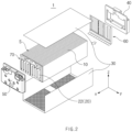
- FIG. 2 is an exploded perspective view illustrating a battery module inspected in a battery module inspection method according to an embodiment of the present invention.
- FIG. 3 is a front view illustrating a first vision inspection process in a battery module inspection method according to an embodiment of the present invention.
- FIG. 4 is a schematic perspective view illustrating a first vision inspection process in a battery module inspection method according to an embodiment of the present invention.
- FIG. 6 is a front view illustrating a second vision inspection process in a battery module inspection method according to an embodiment of the present invention.
- the battery module inspection method may include a first vision inspection process of inspecting the number and positions of electrode leads 20 provided in multiple battery cells 10, respectively, through vision cameras 110 and 120, and a second vision inspection process of inspecting the number and bending states of the electrode leads 20 provided in the multiple battery cells 10, respectively, through the vision cameras 110 and 120.
- the battery module inspection method according to an embodiment of the present invention may further include a third vision inspection process of photographing lower portions of the electrode leads 20 through the vision cameras 110 and 120 to inspect the number and positions of the electrode leads 20.
- a battery module 1 inspected in the battery module inspection method may include a cell stack S, in which the multiple battery cells 10 are stacked, busbar frames 60 and 70, each of which electrically connects the electrode leads 20 of the multiple battery cells 10 to each other, and a module case 30 that accommodates the cell stack S and the busbar frames 60 and 70 therein.
- the battery module may further include end plates 40 and 50 that cover openings at both sides, respectively, of the module case 30.
- a stack in which the multiple battery cells 10, each of which includes an electrolyte, are stacked may be provided.
- Each of the battery cells 10 may include an electrode assembly, the electrolyte, and a pouch that accommodates the electrode assembly and the electrolyte therein.
- the electrode assembly is a power generating device that is chargeable and dischargeable, and an electrode and a separator may be alternately stacked therein.
- the electrode may include a positive electrode and a negative electrode, and the positive electrode, the separator, and the negative electrode may be alternately stacked.
- the separator separates and electrically insulates the positive electrode and the negative electrode from each other.
- the battery cell 10 may further include the electrode lead 20 having one side portion connected to the electrode of the electrode assembly and the other side portion extending to the outside of the pouch.
- the electrode lead 20 may include a positive electrode lead 21 connected to the positive electrode and a negative electrode lead 22 connected to the negative electrode.
- FIG. 5 is a plan view illustrating a state in which an electrode lead is photographed by a vision camera in a first vision inspection process of a battery module inspection method according to an embodiment of the present invention.
- the cell stack S in which the multiple battery cells 10 are stacked may be inspected, and the number and positions of the electrode leads 20 provided in the multiple battery cells 10, respectively, may be inspected through the vision cameras 110 and 120.
- the first vision inspection process may be performed before the cell stack S is assembled with the busbar frames 60 and 70.
- Upper portions of the electrode leads 20 inserted into insulation blocks 150 and 160 may be photographed through the vision cameras 110 and 120 to inspect the number and positions of the electrode leads 20 in the first vision inspection process.
- an end 20a of the electrode lead 20 in each of multiple virtual rectangular shapes L1, the number of which is the same as the number of the multiple electrode leads 20, may be detected to check the number and position thereof in the first vision inspection process.
- an upper portion of the positive electrode lead 21 may be photographed by each of the vision cameras, and when one end 21a of the positive electrode lead 21 is disposed in each of the multiple virtual rectangular shapes L1, it may be determined to be normal.
- the defect determination of the negative electrode lead 22 may be also carried out like the defect determination of the positive electrode lead 21.
- the electrode leads 20 may be illuminated through illuminators 130 and 140 during the inspection of the electrode leads 20 through the vision cameras 110 and 120.
- the illuminators 130 and 140 may be provided as bar illuminators 130 and 140.
- the electrode leads 20 may be illuminated through the illuminators 130 and 140 in an upper diagonal direction based on a direction in which the electrode leads 20 extend.
- the number and position defects of the stacked battery cells of the cell stack S may be easily detected through the first vision inspection process before the cell stack S and the busbar frames 60 and 70 are assembled.
- it may be easily inspected through the first vision inspection process whether it is possible to assemble the cell stack S and the busbar frames 60 and 70, before the cell stack S and the busbar frames 60 and 70 are assembled.
- FIG. 7 is a schematic perspective view exemplarily illustrating a concept of a second vision inspection process in a battery module inspection method according to an embodiment of the present invention.
- FIG. 8 is a side view illustrating a state in which an electrode lead is photographed by a vision camera in a second vision inspection process of a battery module inspection method according to an embodiment of the present invention.
- FIG. 7 schematically simply illustrates a busbar frame.
- the number and bending states of the electrode leads 20 provided in the multiple battery cells 10, respectively, may be inspected through the vision cameras 110 and 120.
- front surfaces of the electrode leads 20 may be photographed through the vision cameras 110 and 120 to inspect the number and bending states of the electrode leads 20 in the second vision inspection process.
- the second vision inspection process may be performed after the cell stack S is assembled with the busbar frames 60 and 70. Accordingly, occurrences of the erroneous insertion and bending defects of the electrode lead 20 may be easily detected through the second vision inspection process when the cell stack S is assembled with the busbar frames 60 and 70. Assembly defects of the cell stack S and the busbar frames 60 and 70 may be also easily detected through the second vision inspection process.
- the end 20a of the electrode lead 20 in each of multiple virtual rectangular shapes L2, the number of which is same as the number of the multiple electrode leads 20, may be detected to check the number.
- it may be determined to be defective, and when two or more electrode leads 20 are detected in each of the multiple virtual rectangular shapes L2, it may be determined as redundant insertion to be defective.
- the end 20a of the electrode lead 20 may be detected to track a length thereof, and when an end length E of the detected electrode lead 20 is detected to be less 3.3% or more than an end length of a regular electrode lead, it may be determined as a bending defect.
- a length of a bending portion is 2 mm or more in a specification of the electrode lead 20 of which a length is 30 mm, it may be determined to be defective.
- the electrode leads 20 may be illuminated through the illuminators 130 and 140 in a direction facing the direction in which the electrode leads 20 extend.
- an axial direction in which the electrode lead 20 extends and a light axis of each of the illuminators 130 and 140 may be a coaxial direction in the second vision inspection process.
- FIG. 9 is a front view illustrating a third vision inspection process in a battery module inspection method according to an embodiment of the present invention.
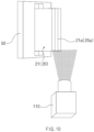
- FIG. 10 is a schematic perspective view exemplarily illustrating a concept of a third vision inspection process in a battery module inspection method according to an embodiment of the present invention.
- FIG. 10 schematically simply illustrates a busbar frame.
- the number and positions of the electrode leads 20 provided in the multiple battery cells 10, respectively, may be inspected through the vision cameras 110 and 120 after the cell stack S is assembled with the busbar frames 60 and 70.
- the lower portions of the electrode leads 20 may be photographed through the vision cameras 110 and 120 to inspect the number and positions of the electrode leads 20 in the third vision inspection process.
- the electrode leads 20 may be illuminated through the illuminators 130 and 140 in a lower diagonal direction based on the direction in which the electrode leads 20 extend.
- the electrode lead 20 may be easily inspected through the third vision inspection process whether the electrode lead 20 is erroneously inserted into each of the busbar frames 60 and 70 or there is no defect of an insertion length, after the cell stack S is assembled with the busbar frames 60 and 70. Accordingly, an assembled state of the cell stack S and the busbar frames 60 and 70 may be easily detected through the third vision inspection process.
- an end of the electrode lead 20 in each of multiple virtual rectangular shapes may be detected to check the number and position thereof in the third vision inspection process like the defect discrimination method of the first vision inspection process.
- it may be determined to be defective, and when two or more electrode leads 20 are detected in each of the multiple virtual rectangular shapes, it may be determined as redundant insertion to be defective.
- each of the vision cameras 110 and 120 and the illuminators 130 and 140 used in the first vision inspection process, the second vision inspection process, and the third vision inspection process may be moved to a fixed position by a moving means.
- each of the vision cameras 110 and 120 and the illuminators 130 and 140 may move upward from the electrode lead 20 of the battery cell 10 in the first vision inspection process, move coaxially together with the electrode lead 20 based on the electrode lead 20 of the battery cell 10 in the second vision inspection process, and move downward from the electrode lead 20 of the battery cell 10 in the third vision inspection process.
- the moving means may include a frame, in which each of the vision cameras 110 and 120 and the illuminators 130 and 140 is mounted, and a rotating part that rotates the frame.
- the rotating part may include a servo motor that rotates a rotary shaft of the rotating part.
- the battery module inspection method may prevent the occurrence of the erroneous inspections by automatically performing the vision inspection through the vision cameras 110 and 120 when the cell stack S in which the multiple battery cells 10 are stacked is inspected during the manufacturing of the battery module 1.
- Battery module 10 Battery cell 20: Electrode lead 20a: End 21: Positive electrode lead 21a: End 22: Negative electrode lead 30: Module case 40, 50: End plate 60, 70: Busbar frame 110, 120: Vision camera 130, 140: Illuminator 150, 160: Insulation block S: Cell stack E: End length
Landscapes
- Chemical & Material Sciences (AREA)
- Chemical Kinetics & Catalysis (AREA)
- General Chemical & Material Sciences (AREA)
- Electrochemistry (AREA)
- General Health & Medical Sciences (AREA)
- Biochemistry (AREA)
- Physics & Mathematics (AREA)
- General Physics & Mathematics (AREA)
- Immunology (AREA)
- Pathology (AREA)
- Analytical Chemistry (AREA)
- Life Sciences & Earth Sciences (AREA)
- Health & Medical Sciences (AREA)
- Battery Mounting, Suspending (AREA)
Abstract
Description
- The present application claims the benefit of the priority of
Korean Patent Application Nos. 10-2022-0012733, filed on January 27, 2022 10-2023-0010161, filed on January 26, 2023 - The present invention relates to a battery module inspection method.
- Secondary batteries are rechargeable unlike primary batteries and capable of being reduced in size and increasing capacity and thus, much research and development for the secondary batteries are carried out recently. As the technical development of and a demand for mobile devices increase, a demand for the secondary batteries as energy sources rapidly increases.
- According to shapes of a battery case, the secondary batteries are classified into coin type batteries, cylindrical type batteries, prismatic type batteries, and pouch type batteries. In the secondary batteries, an electrode assembly mounted in a battery case is a chargeable and dischargeable power generating device having a structure in which an electrode and a separator are stacked.
- The secondary batteries attract a lot of interest as energy sources not only for mobile devices, such as mobile phones, digital cameras, and notebook computers, but also for power systems of electric bikes, electric vehicles, hybrid electric vehicles, and the like.
- A small-sized battery pack in which one battery cell is packed is used in small-sized devices such as mobile devices or cameras, but a medium to large-sized battery pack in which a battery pack having two or more battery cells connected to each other in parallel and/or in series is packed is used in medium to large-sized devices such as notebook computers or electric vehicles. Thus, the number of the battery cells included in the battery pack may be variously set according to an output voltage or charge/discharge capacity required.
- Meanwhile, when a plurality of battery cells are connected to each other in parallel/series so as to configure the battery pack, it is a general method that a battery module constituted by at least one battery pack is configured and then, such at least one battery module is used to configure the battery pack by addition of other components. The number of the battery module included in the battery pack or the number of the battery cell included in the battery module may be variously set according to an output voltage or charge/discharge capacity required. The battery module set thus is configured by including a plurality of battery cells, which are stacked, and a busbar frame that electrically connects electrode leads of the plurality of battery cells to each other.
- According to the related art, inspections before and after assembling of an ICB busbar frame assembly (Busbar Frame Assy) are carried out through visual inspection work by a worker. Accordingly, erroneous inspections occur due to human inspection errors caused by the inspections relying on the worker. In addition, manual inspections of the ICB busbar frame assembly (Busbar Frame Assy) are carried out and thus, labor costs are increased.
- One aspect of the present invention is to provide a battery module inspection method capable of preventing an erroneous inspection from occurring when a cell stack in which multiple battery cells are stacked is inspected during manufacturing of a battery module.
- A battery module inspection method according to an embodiment of the present invention may include: a first vision inspection process of inspecting a cell stack in which multiple battery cells are stacked, wherein the number and positions of electrode leads provided in the multiple battery cells, respectively, are inspected through a vision camera; and a second vision inspection process of inspecting the number and bending states of the electrode leads provided in the multiple battery cells, respectively, through the vision camera after the first vision inspection process.
- According to the present invention, the occurrence of the erroneous inspections may be prevented by automatically performing the vision inspection through the vision camera when the cell stack in which the multiple battery cells are stacked is inspected during the manufacturing of the battery module.
-
-
FIG. 1 is a perspective view illustrating a battery module inspected in a battery module inspection method according to an embodiment of the present invention. -
FIG. 2 is an exploded perspective view illustrating a battery module inspected in a battery module inspection method according to an embodiment of the present invention. -
FIG. 3 is a front view illustrating a first vision inspection process in a battery module inspection method according to an embodiment of the present invention. -
FIG. 4 is a schematic perspective view illustrating a first vision inspection process in a battery module inspection method according to an embodiment of the present invention. -
FIG. 5 is a plan view illustrating a state in which an electrode lead is photographed by a vision camera in a first vision inspection process of a battery module inspection method according to an embodiment of the present invention. -
FIG. 6 is a front view illustrating a second vision inspection process in a battery module inspection method according to an embodiment of the present invention. -
FIG. 7 is a schematic perspective view exemplarily illustrating a concept of a second vision inspection process in a battery module inspection method according to an embodiment of the present invention. -
FIG. 8 is a side view illustrating a state in which an electrode lead is photographed by a vision camera in a second vision inspection process of a battery module inspection method according to an embodiment of the present invention. -
FIG. 9 is a front view illustrating a third vision inspection process in a battery module inspection method according to an embodiment of the present invention. -
FIG. 10 is a schematic perspective view exemplarily illustrating a concept of a third vision inspection process in a battery module inspection method according to an embodiment of the present invention. - The purpose, specified advantages, and novel features of the present invention will be clarified through the following detailed description and preferred embodiments taken in conjunction with the accompanying drawings. Note that like elements are designated by like reference numerals as far as possible even if they are shown in different drawings. The present invention may be embodied in different forms and should not be construed as limited to the embodiments set forth herein. Moreover, detailed descriptions related to well-known art will be ruled out in order not to unnecessarily obscure subject matters of the present invention.
-
FIG. 1 is a perspective view illustrating a battery module inspected in a battery module inspection method according to an embodiment of the present invention.FIG. 2 is an exploded perspective view illustrating a battery module inspected in a battery module inspection method according to an embodiment of the present invention. - In addition,
FIG. 3 is a front view illustrating a first vision inspection process in a battery module inspection method according to an embodiment of the present invention.FIG. 4 is a schematic perspective view illustrating a first vision inspection process in a battery module inspection method according to an embodiment of the present invention.FIG. 6 is a front view illustrating a second vision inspection process in a battery module inspection method according to an embodiment of the present invention. - Referring to
FIGS. 1 to 6 , the battery module inspection method according to an embodiment of the present invention may include a first vision inspection process of inspecting the number and positions of electrode leads 20 provided inmultiple battery cells 10, respectively, throughvision cameras multiple battery cells 10, respectively, through thevision cameras vision cameras - In more detail, referring to
FIGS. 1 and2 , abattery module 1 inspected in the battery module inspection method according to an embodiment of the present invention may include a cell stack S, in which themultiple battery cells 10 are stacked,busbar frames multiple battery cells 10 to each other, and amodule case 30 that accommodates the cell stack S and thebusbar frames end plates module case 30. - In the cell stack S, a stack in which the
multiple battery cells 10, each of which includes an electrolyte, are stacked may be provided. - Each of the
battery cells 10 may include an electrode assembly, the electrolyte, and a pouch that accommodates the electrode assembly and the electrolyte therein. - The electrode assembly is a power generating device that is chargeable and dischargeable, and an electrode and a separator may be alternately stacked therein. Here, the electrode may include a positive electrode and a negative electrode, and the positive electrode, the separator, and the negative electrode may be alternately stacked. Here, the separator separates and electrically insulates the positive electrode and the negative electrode from each other.
- The
battery cell 10 may further include theelectrode lead 20 having one side portion connected to the electrode of the electrode assembly and the other side portion extending to the outside of the pouch. - The
electrode lead 20 may include apositive electrode lead 21 connected to the positive electrode and anegative electrode lead 22 connected to the negative electrode. -
FIG. 5 is a plan view illustrating a state in which an electrode lead is photographed by a vision camera in a first vision inspection process of a battery module inspection method according to an embodiment of the present invention. - Referring to
FIGS. 2 and3 to 5 , in the first vision inspection process, the cell stack S in which themultiple battery cells 10 are stacked may be inspected, and the number and positions of the electrode leads 20 provided in themultiple battery cells 10, respectively, may be inspected through thevision cameras - The first vision inspection process may be performed before the cell stack S is assembled with the
busbar frames - Upper portions of the electrode leads 20 inserted into
insulation blocks vision cameras - In addition, an
end 20a of theelectrode lead 20 in each of multiple virtual rectangular shapes L1, the number of which is the same as the number of the multiple electrode leads 20, may be detected to check the number and position thereof in the first vision inspection process. Here, when even oneelectrode lead 20 is not detected in each of the multiple virtual rectangular shapes L1, it may be determined to be defective, and when two or more electrode leads 20 are detected in each of the multiple virtual rectangular shapes L1, it may be determined as redundant insertion to be defective. Here, for a specific example, an upper portion of thepositive electrode lead 21 may be photographed by each of the vision cameras, and when oneend 21a of thepositive electrode lead 21 is disposed in each of the multiple virtual rectangular shapes L1, it may be determined to be normal. The defect determination of thenegative electrode lead 22 may be also carried out like the defect determination of thepositive electrode lead 21. In the first vision inspection process, the electrode leads 20 may be illuminated throughilluminators vision cameras illuminators bar illuminators - In the first vision inspection process, the second vision inspection process, and the third vision inspection process, the electrode leads 20 may be illuminated through the
illuminators - Accordingly, the number and position defects of the stacked battery cells of the cell stack S may be easily detected through the first vision inspection process before the cell stack S and the busbar frames 60 and 70 are assembled. Thus, it may be easily inspected through the first vision inspection process whether it is possible to assemble the cell stack S and the busbar frames 60 and 70, before the cell stack S and the busbar frames 60 and 70 are assembled.
-
FIG. 7 is a schematic perspective view exemplarily illustrating a concept of a second vision inspection process in a battery module inspection method according to an embodiment of the present invention.FIG. 8 is a side view illustrating a state in which an electrode lead is photographed by a vision camera in a second vision inspection process of a battery module inspection method according to an embodiment of the present invention.FIG. 7 schematically simply illustrates a busbar frame. - Referring to
FIGS. 2 ,6 and8 , in the second vision inspection process, the number and bending states of the electrode leads 20 provided in themultiple battery cells 10, respectively, may be inspected through thevision cameras - In addition, front surfaces of the electrode leads 20 may be photographed through the
vision cameras electrode lead 20 may be easily detected through the second vision inspection process when the cell stack S is assembled with the busbar frames 60 and 70. Assembly defects of the cell stack S and the busbar frames 60 and 70 may be also easily detected through the second vision inspection process. - Referring to
FIGS. 7 and8 , in a method for inspecting the number of theelectrode lead 20 in the second vision inspection process, theend 20a of theelectrode lead 20 in each of multiple virtual rectangular shapes L2, the number of which is same as the number of the multiple electrode leads 20, may be detected to check the number. Here, when even oneelectrode lead 20 is not detected in each of the multiple virtual rectangular shapes L2, it may be determined to be defective, and when two or more electrode leads 20 are detected in each of the multiple virtual rectangular shapes L2, it may be determined as redundant insertion to be defective. - In a method for inspecting the bending state of the
electrode lead 20 in the second vision inspection process, theend 20a of theelectrode lead 20 may be detected to track a length thereof, and when an end length E of the detectedelectrode lead 20 is detected to be less 3.3% or more than an end length of a regular electrode lead, it may be determined as a bending defect. Here, for example, when a length of a bending portion is 2 mm or more in a specification of theelectrode lead 20 of which a length is 30 mm, it may be determined to be defective. - In addition, referring to
FIGS. 6 and7 , in the second vision inspection process, the electrode leads 20 may be illuminated through theilluminators electrode lead 20 extends and a light axis of each of theilluminators -
FIG. 9 is a front view illustrating a third vision inspection process in a battery module inspection method according to an embodiment of the present invention.FIG. 10 is a schematic perspective view exemplarily illustrating a concept of a third vision inspection process in a battery module inspection method according to an embodiment of the present invention.FIG. 10 schematically simply illustrates a busbar frame. - Referring to
FIGS. 2 ,9 and10 , in the third vision inspection process, the number and positions of the electrode leads 20 provided in themultiple battery cells 10, respectively, may be inspected through thevision cameras - The lower portions of the electrode leads 20 may be photographed through the
vision cameras - In the third vision inspection process, the electrode leads 20 may be illuminated through the
illuminators - Thus, it may be easily inspected through the third vision inspection process whether the
electrode lead 20 is erroneously inserted into each of the busbar frames 60 and 70 or there is no defect of an insertion length, after the cell stack S is assembled with the busbar frames 60 and 70. Accordingly, an assembled state of the cell stack S and the busbar frames 60 and 70 may be easily detected through the third vision inspection process. - In addition, an end of the
electrode lead 20 in each of multiple virtual rectangular shapes, the number of which is the same as the number of the multiple electrode leads 20, may be detected to check the number and position thereof in the third vision inspection process like the defect discrimination method of the first vision inspection process. Here, when even oneelectrode lead 20 is not detected in each of the multiple virtual rectangular shapes, it may be determined to be defective, and when two or more electrode leads 20 are detected in each of the multiple virtual rectangular shapes, it may be determined as redundant insertion to be defective. - Meanwhile, each of the
vision cameras illuminators - Through the moving means, each of the
vision cameras illuminators electrode lead 20 of thebattery cell 10 in the first vision inspection process, move coaxially together with theelectrode lead 20 based on theelectrode lead 20 of thebattery cell 10 in the second vision inspection process, and move downward from theelectrode lead 20 of thebattery cell 10 in the third vision inspection process. - Here, the moving means may include a frame, in which each of the
vision cameras illuminators - The battery module inspection method according to an embodiment of the present invention configured as above may prevent the occurrence of the erroneous inspections by automatically performing the vision inspection through the
vision cameras multiple battery cells 10 are stacked is inspected during the manufacturing of thebattery module 1. - Although the present invention has been described in detail with reference to the limited embodiments and the accompanying drawings, the present invention is not limited thereto. The present invention may be variously implemented by those of ordinary skill in the art, to which the present invention pertains, within the technical idea of the present invention.
- Moreover, the specific protective scope of the present invention will be clarified by the accompanying claims.
-
[Description of the Symbols] 1: Battery module 10: Battery cell 20: Electrode lead 20a: End 21: Positive electrode lead 21a: End 22: Negative electrode lead 30: Module case 40, 50: End plate 60, 70: Busbar frame 110, 120: Vision camera 130, 140: Illuminator 150, 160: Insulation block S: Cell stack E: End length
Claims (10)
- A battery module inspection method comprising:a first vision inspection process of inspecting a cell stack in which multiple battery cells are stacked, wherein the number and positions of electrode leads provided in the multiple battery cells, respectively, are inspected through a vision camera; anda second vision inspection process of inspecting the number and bending states of the electrode leads provided in the multiple battery cells, respectively, through the vision camera after the first vision inspection process.
- The battery module inspection method of claim 1, wherein the first vision inspection process is performed before the cell stack is assembled with a busbar frame, and
the second vision inspection process is performed after the cell stack is assembled with the busbar frame. - The battery module inspection method of claim 1, wherein, in the first vision inspection process, upper portions of the electrode leads inserted into an insulation block are photographed through the vision camera so as to inspect the number and positions of the electrode leads.
- The battery module inspection method of claim 1, wherein, in the second vision inspection process, front surfaces of the electrode leads are photographed through the vision camera so as to inspect the number and bending states of the electrode leads.
- The battery module inspection method of claim 1, further comprising a third vision inspection process of inspecting the number and positions of the electrode leads provided in the multiple battery cells, respectively, through the vision camera after the cell stack is assembled with the busbar frame.
- The battery module inspection method of claim 5, wherein, in the third vision inspection process, lower portions of the electrode leads are photographed through the vision camera so as to inspect the number and positions of the electrode leads.
- The battery module inspection method of claim 6, wherein, in the first vision inspection process, the second vision inspection process, and the third vision inspection process, when the electrode leads are inspected through the vision camera, the electrode leads are illuminated through an illuminator.
- The battery module inspection method of claim 7, wherein, in the first vision inspection process, the electrode leads are illuminated through the illuminator in an upper diagonal direction based on a direction in which the electrode leads extend.
- The battery module inspection method of claim 7, wherein, in the second vision inspection process, the electrode leads are illuminated through the illuminator in a direction facing a direction in which the electrode leads extend.
- The battery module inspection method of claim 7, wherein, in the third vision inspection process, the electrode leads are illuminated through the illuminator in a lower diagonal direction based on a direction in which the electrode leads extend.
Applications Claiming Priority (3)
| Application Number | Priority Date | Filing Date | Title |
|---|---|---|---|
| KR20220012733 | 2022-01-27 | ||
| KR1020230010161A KR20230115923A (en) | 2022-01-27 | 2023-01-26 | battery module inspection method |
| PCT/KR2023/001288 WO2023146350A1 (en) | 2022-01-27 | 2023-01-27 | Method for inspecting battery module |
Publications (3)
| Publication Number | Publication Date |
|---|---|
| EP4447190A1 true EP4447190A1 (en) | 2024-10-16 |
| EP4447190A4 EP4447190A4 (en) | 2025-04-02 |
| EP4447190B1 EP4447190B1 (en) | 2026-04-22 |
Family
ID=87472110
Family Applications (1)
| Application Number | Title | Priority Date | Filing Date |
|---|---|---|---|
| EP23747391.3A Active EP4447190B1 (en) | 2022-01-27 | 2023-01-27 | Battery module inspection method |
Country Status (4)
| Country | Link |
|---|---|
| US (1) | US20250341474A1 (en) |
| EP (1) | EP4447190B1 (en) |
| JP (1) | JP7810495B2 (en) |
| WO (1) | WO2023146350A1 (en) |
Families Citing this family (2)
| Publication number | Priority date | Publication date | Assignee | Title |
|---|---|---|---|---|
| CN117058138B (en) * | 2023-10-11 | 2024-03-22 | 宁德时代新能源科技股份有限公司 | Battery module verification method and device |
| KR20260001260A (en) * | 2024-06-27 | 2026-01-05 | 주식회사 엘지에너지솔루션 | Method for monitoring bending position of electrode tabs and electrode assembly winding device using the same |
Family Cites Families (11)
| Publication number | Priority date | Publication date | Assignee | Title |
|---|---|---|---|---|
| JP4892813B2 (en) * | 2004-05-26 | 2012-03-07 | トヨタ自動車株式会社 | Single cell inspection method and assembled battery assembly method |
| JP5555156B2 (en) * | 2010-12-28 | 2014-07-23 | プライムアースEvエナジー株式会社 | Inspection method for secondary battery structure |
| DE102012020358B3 (en) * | 2012-10-17 | 2014-02-13 | Audi Ag | Device for mounting holding frame with bus bars at battery module e.g. lithium-ion-battery module in electric vehicle, has detection unit for controlling locking device for releasing mobility of movement device based on detection result |
| JP2015170402A (en) * | 2014-03-05 | 2015-09-28 | 昭和電工パッケージング株式会社 | Inspection method of tab lead and inspection apparatus of tab lead |
| JP6659483B2 (en) * | 2016-07-05 | 2020-03-04 | 株式会社エンビジョンAescジャパン | Inspection method of joining condition between electrode tab and bus bar |
| KR102162874B1 (en) * | 2017-01-20 | 2020-10-07 | 주식회사 엘지화학 | Defect inspection device of electrode lead for secondary battery |
| CN108375544A (en) * | 2018-01-11 | 2018-08-07 | 多氟多(焦作)新能源科技有限公司 | A method of for detecting laminated battery plate lug bending |
| KR102081671B1 (en) * | 2018-08-28 | 2020-02-26 | 주식회사 폴 | Two Column Automatic Inspection System of Lead Tap for Senconday Battery |
| KR102403207B1 (en) * | 2020-04-07 | 2022-05-30 | (주)펨트론 | System for inspecting and loading lead tabs in multiple rows |
| KR102409650B1 (en) * | 2020-04-07 | 2022-06-17 | (주)펨트론 | System for inspecting lead tabs in multiple rows |
| KR102851616B1 (en) * | 2020-07-15 | 2025-08-28 | 주식회사 엘지에너지솔루션 | Electrode Lead Bending and Welding Device and Welding Method Using the Same |
-
2023
- 2023-01-27 EP EP23747391.3A patent/EP4447190B1/en active Active
- 2023-01-27 JP JP2024542193A patent/JP7810495B2/en active Active
- 2023-01-27 WO PCT/KR2023/001288 patent/WO2023146350A1/en not_active Ceased
- 2023-01-27 US US18/728,688 patent/US20250341474A1/en active Pending
Also Published As
| Publication number | Publication date |
|---|---|
| EP4447190A4 (en) | 2025-04-02 |
| WO2023146350A1 (en) | 2023-08-03 |
| US20250341474A1 (en) | 2025-11-06 |
| JP7810495B2 (en) | 2026-02-03 |
| EP4447190B1 (en) | 2026-04-22 |
| JP2025502330A (en) | 2025-01-24 |
Similar Documents
| Publication | Publication Date | Title |
|---|---|---|
| EP4447190A1 (en) | Method for inspecting battery module | |
| JP5465726B2 (en) | Lithium secondary battery unit set with bus bar and lithium secondary battery set with bus bar | |
| EP1829136B1 (en) | Battery cartridge for novel structure and open type battery module containing the same | |
| US7740981B2 (en) | Assembled battery including insulating support plate connected to a terminal surface | |
| EP2393141A2 (en) | Cell cartridge with a composite intercell connecting net structure | |
| EP2445047A2 (en) | Instrument connection type unit pack combined cell cartridge | |
| KR20090043429A (en) | Lithium Secondary Battery Unit Set and Lithium Secondary Battery Set | |
| US11018391B2 (en) | Battery cell, battery module, and battery pack and vehicle including the same | |
| EP0949698A2 (en) | Battery pack, battery charger and electronic equipment using battery pack | |
| WO2018236022A1 (en) | Battery pack | |
| EP4539196A1 (en) | Battery exterior inspection equipment | |
| EP4113696A1 (en) | System for detecting defect of electrode tab and method for detecting defect of electrode tab by using same | |
| WO2023197117A1 (en) | Measurement method and apparatus for tab | |
| KR101047991B1 (en) | Lithium secondary battery case having an end frame with an accommodating part and a lithium secondary battery set with an end frame with an accommodating part | |
| CN118511359A (en) | Battery module inspection method | |
| KR20230115923A (en) | battery module inspection method | |
| EP4310986A1 (en) | Bonding state inspection apparatus and bonding state inspection method using same | |
| EP4431920A1 (en) | Welding inspection device | |
| WO2023136487A1 (en) | Battery pack assembly having impact absorption function and apparatus and method for manufacturing same | |
| US20260003001A1 (en) | Method and apparatus for monitoring self-discharge phenomena of electrochemical cells | |
| KR102945543B1 (en) | Battery Module Testing Device | |
| US12621554B2 (en) | Welding inspection apparatus for inspecting a battery can | |
| US20260002998A1 (en) | Method and apparatus for monitoring self-discharge phenomena of electrochemical cells | |
| WO2026071617A1 (en) | Secondary battery comprising cell lead having hole for gap measurement, and method for welding cell lead | |
| CN119310112A (en) | Battery cell tray and detection device |
Legal Events
| Date | Code | Title | Description |
|---|---|---|---|
| STAA | Information on the status of an ep patent application or granted ep patent |
Free format text: STATUS: THE INTERNATIONAL PUBLICATION HAS BEEN MADE |
|
| PUAI | Public reference made under article 153(3) epc to a published international application that has entered the european phase |
Free format text: ORIGINAL CODE: 0009012 |
|
| STAA | Information on the status of an ep patent application or granted ep patent |
Free format text: STATUS: REQUEST FOR EXAMINATION WAS MADE |
|
| 17P | Request for examination filed |
Effective date: 20240709 |
|
| AK | Designated contracting states |
Kind code of ref document: A1 Designated state(s): AL AT BE BG CH CY CZ DE DK EE ES FI FR GB GR HR HU IE IS IT LI LT LU LV MC ME MK MT NL NO PL PT RO RS SE SI SK SM TR |
|
| REG | Reference to a national code |
Ref country code: DE Ref legal event code: R079 Free format text: PREVIOUS MAIN CLASS: H01M0010420000 Ipc: G01N0021950000 Ref document number: 602023015797 Country of ref document: DE |
|
| A4 | Supplementary search report drawn up and despatched |
Effective date: 20250227 |
|
| RIC1 | Information provided on ipc code assigned before grant |
Ipc: H01M 50/557 20210101ALI20250221BHEP Ipc: H01M 50/514 20210101ALI20250221BHEP Ipc: H01M 50/507 20210101ALI20250221BHEP Ipc: H01M 50/211 20210101ALI20250221BHEP Ipc: G01N 21/88 20060101ALI20250221BHEP Ipc: G01N 21/95 20060101AFI20250221BHEP |
|
| DAV | Request for validation of the european patent (deleted) | ||
| DAX | Request for extension of the european patent (deleted) | ||
| GRAP | Despatch of communication of intention to grant a patent |
Free format text: ORIGINAL CODE: EPIDOSNIGR1 |
|
| STAA | Information on the status of an ep patent application or granted ep patent |
Free format text: STATUS: GRANT OF PATENT IS INTENDED |
|
| RIC1 | Information provided on ipc code assigned before grant |
Ipc: G01N 21/95 20060101AFI20251110BHEP Ipc: G01N 21/88 20060101ALI20251110BHEP Ipc: H01M 50/211 20210101ALI20251110BHEP Ipc: H01M 50/507 20210101ALI20251110BHEP Ipc: H01M 50/514 20210101ALI20251110BHEP Ipc: H01M 50/557 20210101ALI20251110BHEP |
|
| INTG | Intention to grant announced |
Effective date: 20251119 |
|
| P01 | Opt-out of the competence of the unified patent court (upc) registered |
Free format text: CASE NUMBER: UPC_APP_0015396_4447190/2025 Effective date: 20251201 |
|
| GRAS | Grant fee paid |
Free format text: ORIGINAL CODE: EPIDOSNIGR3 |
|
| GRAA | (expected) grant |
Free format text: ORIGINAL CODE: 0009210 |
|
| STAA | Information on the status of an ep patent application or granted ep patent |
Free format text: STATUS: THE PATENT HAS BEEN GRANTED |
|
| AK | Designated contracting states |
Kind code of ref document: B1 Designated state(s): AL AT BE BG CH CY CZ DE DK EE ES FI FR GB GR HR HU IE IS IT LI LT LU LV MC ME MK MT NL NO PL PT RO RS SE SI SK SM TR |
|
| REG | Reference to a national code |
Ref country code: CH Ref legal event code: F10 Free format text: ST27 STATUS EVENT CODE: U-0-0-F10-F00 (AS PROVIDED BY THE NATIONAL OFFICE) Effective date: 20260422 Ref country code: GB Ref legal event code: FG4D |