EP4447027A1 - Splicing assembly and splicing display screen - Google Patents
Splicing assembly and splicing display screen Download PDFInfo
- Publication number
- EP4447027A1 EP4447027A1 EP21827169.0A EP21827169A EP4447027A1 EP 4447027 A1 EP4447027 A1 EP 4447027A1 EP 21827169 A EP21827169 A EP 21827169A EP 4447027 A1 EP4447027 A1 EP 4447027A1
- Authority
- EP
- European Patent Office
- Prior art keywords
- tiling
- mortise
- connector
- positioning portion
- tenon
- Prior art date
- Legal status (The legal status is an assumption and is not a legal conclusion. Google has not performed a legal analysis and makes no representation as to the accuracy of the status listed.)
- Pending
Links
Images




Classifications
-
- F—MECHANICAL ENGINEERING; LIGHTING; HEATING; WEAPONS; BLASTING
- F16—ENGINEERING ELEMENTS AND UNITS; GENERAL MEASURES FOR PRODUCING AND MAINTAINING EFFECTIVE FUNCTIONING OF MACHINES OR INSTALLATIONS; THERMAL INSULATION IN GENERAL
- F16B—DEVICES FOR FASTENING OR SECURING CONSTRUCTIONAL ELEMENTS OR MACHINE PARTS TOGETHER, e.g. NAILS, BOLTS, CIRCLIPS, CLAMPS, CLIPS OR WEDGES; JOINTS OR JOINTING
- F16B5/00—Joining sheets or plates, e.g. panels, to one another or to strips or bars parallel to them
- F16B5/0004—Joining sheets, plates or panels in abutting relationship
-
- H—ELECTRICITY
- H05—ELECTRIC TECHNIQUES NOT OTHERWISE PROVIDED FOR
- H05K—PRINTED CIRCUITS; CASINGS OR CONSTRUCTIONAL DETAILS OF ELECTRIC APPARATUS; MANUFACTURE OF ASSEMBLAGES OF ELECTRICAL COMPONENTS
- H05K5/00—Casings, cabinets or drawers for electric apparatus
- H05K5/30—Side-by-side or stacked arrangements
-
- G—PHYSICS
- G09—EDUCATION; CRYPTOGRAPHY; DISPLAY; ADVERTISING; SEALS
- G09F—DISPLAYING; ADVERTISING; SIGNS; LABELS OR NAME-PLATES; SEALS
- G09F9/00—Indicating arrangements for variable information in which the information is built-up on a support by selection or combination of individual elements
- G09F9/30—Indicating arrangements for variable information in which the information is built-up on a support by selection or combination of individual elements in which the desired character or characters are formed by combining individual elements
- G09F9/302—Indicating arrangements for variable information in which the information is built-up on a support by selection or combination of individual elements in which the desired character or characters are formed by combining individual elements characterised by the form or geometrical disposition of the individual elements
- G09F9/3026—Video wall, i.e. stackable semiconductor matrix display modules
-
- H—ELECTRICITY
- H05—ELECTRIC TECHNIQUES NOT OTHERWISE PROVIDED FOR
- H05K—PRINTED CIRCUITS; CASINGS OR CONSTRUCTIONAL DETAILS OF ELECTRIC APPARATUS; MANUFACTURE OF ASSEMBLAGES OF ELECTRICAL COMPONENTS
- H05K5/00—Casings, cabinets or drawers for electric apparatus
- H05K5/02—Details
- H05K5/0217—Mechanical details of casings
-
- F—MECHANICAL ENGINEERING; LIGHTING; HEATING; WEAPONS; BLASTING
- F16—ENGINEERING ELEMENTS AND UNITS; GENERAL MEASURES FOR PRODUCING AND MAINTAINING EFFECTIVE FUNCTIONING OF MACHINES OR INSTALLATIONS; THERMAL INSULATION IN GENERAL
- F16B—DEVICES FOR FASTENING OR SECURING CONSTRUCTIONAL ELEMENTS OR MACHINE PARTS TOGETHER, e.g. NAILS, BOLTS, CIRCLIPS, CLAMPS, CLIPS OR WEDGES; JOINTS OR JOINTING
- F16B2200/00—Constructional details of connections not covered for in other groups of this subclass
- F16B2200/83—Use of a magnetic material
Definitions
- the application relates to the technical fields of displays, in particular to a tiling component and a tiled display screen.
- displays are used in a wider and wider range of applications, not only for televisions, monitors, industrial displays and medical displays, but also increasingly used in public display occasions.
- displays are generally required to have a large display area to meet the requirements of people watching from a long distance and displaying larger amounts of information.
- the inventor of the present application finds that the tiling application of the display screen is usually multi-screen linkage, which requires a large number of display modules, and the bezels of the tiling screens require ultra-narrow bezels, such as the ultra-narrow bezel (UNB) type and extreme narrow bezel (ENB) type, and require no tiling gap visually. Therefore, an efficient tiling structure design is needed to ensure efficient screen installation and a design that reduces the tiling gap.
- UOB ultra-narrow bezel
- ENB extreme narrow bezel
- the embodiments of the application provide a tiling component and a tiled display screen, which can achieve efficient tiling and reduce the tiling gap.
- a tiling component including:
- the tiling component provided by the embodiments of the application positions the connector on a tiling panel through the positioning portion to align the connector. Then, a fixation is achieved by fixing a mortise and tenon structure. As a result, multiple tiling panels are efficiently and seamlessly tiled through the connectors.
- the tiling component provided in the embodiments of the application improves the installation efficiency of the tiled display screen and simplifies the installation means. Moreover, it is possible to guarantee a seamless design between the tiling display panels.
- the mortise and tenon structure includes a mortise and a tenon
- the mortise and tenon structure includes a mortise and a tenon; The fixation is achieved by inserting the tenon into the mortise in the connector.
- the connectors can be firmly connected to avoid separation of the connectors.
- an opening width of the mortise gradually increases from the tiling side to a direction away from the tiling side.
- the tiling component provided by the embodiments of the application, when the tiling components generate forces of mutual backwardness, because the opening width on the tiling side is the smallest and gradually increases in a direction away from the tiling side, the inclined planes on the tenon and mortise generate frictions in a direction away from the tiling side to balance the forces that deviate from each other. Therefore, it effectively prevents the tiling component from being pulled apart and ensures the tiling stability of the tiling component.
- the mortise and tenon structure includes a mortise and a tenon
- the positioning portion is arranged on a tiling side of the connector, and the mortise and the positioning portion are arranged spaced apart from each other; the mortise is arranged in the connector away from the tiling side, and the tenon is correspondingly inserted into the mortise and bridging the two connectors.
- the mortise is arranged on the connector away from the tiling side, and the connector can be clamped and fixed at different positions, not limited to the tiling side.
- the bridging of the tenon can connect the connector more firmly.
- an opening width of the mortise gradually increases from the tiling side to a direction away from the tiling side.
- the tiling component provided by the embodiments of the application, when the tiling components generate forces of mutual backwardness, because the opening width on the tiling side is the smallest and gradually increases in a direction away from the tiling side, the inclined planes on the tenon and mortise generate frictions in a direction away from the tiling side to balance the forces that deviate from each other. Therefore, it effectively prevents the tiling component from being pulled apart and ensures the tiling stability of the tiling component.
- the mortise and tenon structure further includes a protrusion portion and a fixture portion, and the protrusion portion protrudes in a direction perpendicular to a surface of the connector;
- a plurality of the mortise and tenon structures are arranged on the connector, and the mortise and tenon structures are arranged on both sides of the positioning portion.
- Configuring the positioning portion in the middle of the connector can make the positioning more accurate.
- the mortise and tenon structures are arranged on both sides of the positioning portion, which can make the connector more stable.
- a plurality of the positioning portions are arranged on the connector, and the positioning portions are arranged on both sides of the mortise and tenon structure.
- configuring a plurality of positioning portions can improve the alignment efficiency of the positioning portion and reduce the alignment error.
- a plurality of the mortise and tenon structures and a plurality of the positioning portions are arranged on the connector, and the mortise and tenon structures and the positioning portions are arranged alternately.
- Adding the positioning portion can increase the positioning accuracy of the positioning portion and align the connector from multiple angles and directions. Moreover, increasing the number of mortises can strengthen the stability of tiling pieces. Furthermore, alternately configuring a plurality of mortises and a plurality of positioning portions can increase the positioning accuracy of each mortise. Thus, the alignment error of the connector is reduced.
- the positioning portion is arranged on the mortise and tenon structure.
- the mortise and tenon structure may include a tenon and a mortise.
- the positioning portion can be provided in the mortise, so that the mortises can be aligned to form a fixed socket after the positioning portion is positioned accurately. Thus, the alignment accuracy of mortises is increased.
- the connector is further provided with a groove, and the positioning portion is embedded in the groove so that a surface of the positioning portion is flush with a surface of the connector.
- Making the surface of the positioning portion flush with the surface of the connector can ensure the distance between the positioning portions while avoiding protrusions on the tiling side, and ensure the positioning of the positioning portion and the attraction effect. Moreover, it avoids the problem that the positioning portion forms the protrusion on the surface of the connector, which leads to an increase in the tiling gap.
- an adhesive layer is arranged in the groove, and the positioning portion is fixed in the groove through the adhesive layer.
- configuring a rubber strip in the groove can prevent the magnetic positioning portion from peeling off or moving.
- material of the positioning portion is a magnetic material, and the positioning portion is matching with a shape of the groove.
- a tiled display screen including:
- the tiled display screen provided by the embodiments of the application adopts a tiling component.
- the tiling component has a connector and a tenon.
- the connector is provided with a positioning portion and a mortise.
- a connector on a tiling panel is positioned by a positioning portion, so that the connector is aligned.
- the fixation is then achieved by inserting the tenon into the mortise in the connector.
- multiple tiling panels are efficiently and seamlessly tiled through the connectors.
- the tiling component provided in the embodiments of the application improves the installation efficiency of the tiled display screen and simplifies the installation means. Moreover, it is possible to guarantee a seamless design between display units.
- the mortise and tenon structure includes a mortise and a tenon
- the mortise and tenon structure includes a mortise and a tenon;
- the fixation is achieved by inserting the tenon into the mortise in the connector.
- the connectors can be firmly connected to avoid separation of the connectors.
- the mortise is arranged on the connector away from the tiling side, and the connector can be clamped and fixed at different positions, not limited to the tiling side.
- the bridging of the tenon can connect the connector more firmly.
- the mortise and tenon structure further includes a protrusion portion and a fixture portion, and the protrusion portion protrudes in a direction perpendicular to a surface of the connector;
- an edge of the connector does not exceed an edge of the tiling panel.
- An edge of the connector does not exceed an edge of the tiling panel, so that the tiling side of the tiling panel is not affected by the tiling component during tiling, so as to reduce the tiling gap.
- a plurality of the tiling components are arranged on a tiling side of each tiling panel, and the tiling components are correspondingly arranged on the tiling sides of adjacent two of the tiling panels.
- increasing a number of the tiling components can prevent the upper and lower ends of tiling components configured on the large-size panels from peeling off.
- the tiling panels can better fix and the efficient tiling of the large-size tiled display screen can be achieved.
- the tiling component is fixed on the tiling panel through a threaded connection.
- the embodiments of the application provide a tiling component and a tiled display screen.
- the tiling component has a connector and a tenon.
- the connector is provided with a positioning portion and a mortise.
- a connector on a tiling panel is positioned by a positioning portion, so that the connector is aligned.
- the fixation is then achieved by inserting the tenon into the mortise in the connector.
- multiple tiling panels are efficiently and seamlessly tiled through the connectors.
- the tiling component provided in the embodiments of the application improves the installation efficiency of the tiled display screen and simplifies the installation means. Moreover, it is possible to guarantee a seamless design between display units.
- the embodiments of the application provide a tiling component and a tiled display screen.
- the following contents are detailed descriptions. It should be noted that the order of description of the following embodiments is not a limitation on the preferred order of the embodiments.
- FIG. 1 is a first schematic structural view of a tiling component provided by an embodiment of the application.
- a tiling component 10a includes a connector 101 and a positioning portion 102.
- the connector 101 is provided with a mortise and tenon structure 103.
- the positioning portion 102 is arranged on the connector 101.
- Two connectors 101 are tiled, and the positioning portions 102 are used to position the two connectors 101.
- the mortise and tenon structure 103 is used to fixedly connect the two connectors 101.
- the tiling component 10a provided by the embodiments of the application positions the connector 101 on a tiling panel through the positioning portion 102 to align the connector 101. Then, a fixation is achieved by fixing a mortise and tenon structure 103. As a result, multiple tiling panels are efficiently and seamlessly tiled through the connectors 101.
- the tiling component 10a provided in the embodiments of the application improves the installation efficiency of the tiled display screen and simplifies the installation means. Moreover, it is possible to guarantee a seamless design between the tiling display panels.
- the mortise and tenon structure 103 includes a mortise 1031 and a tenon 1032.
- the mortise 1011 and the positioning portion 102 are arranged on a tiling side S of the connector 101.
- the mortise 1031 is spaced apart from the positioning portion 102.
- the mortises 1031 on the two connectors 101 are tiled to form a fixed socket 1033.
- the tenon 1032 is correspondingly inserted into the fixed socket 1033 to connect the two connectors 101.
- the tiling component 10a provided in the embodiment of the present application has the connectors 101 and the tenon 1032.
- the connector 101 is provided with a positioning portion 102 and a mortise 1031.
- a connector 101 on a tiling panel is positioned by a positioning portion 102, so that the connector 101 is aligned.
- the tenon 1032 is inserted into the fixed socket 1033 formed by tiling the mortises 1031 on the connectors 101 for fixation.
- the connectors 101 can be firmly connected to avoid separation of the connectors 101.
- the positioning portion 102 includes a mark positioning portion and a magnetic positioning portion.
- the mark positioning portion may be a common alignment mark in the display panel.
- the alignment mark is arranged on the tiling side S of the connector 101, and then the alignment mark is captured through the camera to align the two connectors.
- FIG. 2 is a first schematic structural view of a tiled display screen provided by an embodiment of the application.
- FIG. 3 is a first schematic enlarged view of A in FIG. 2 .
- the tiling component 10a provided in the embodiments of the present application may be applied to a tiled display screen 10.
- the tiled display screen 10 includes a plurality of tiling panel 10b.
- the tiling component 10a is used to tile a plurality of tiling panel 10b.
- FIG. 2 in order to illustrate the position of the tiling component 10a on the tiling panel, it only shows one tiling panel 10b as an example.
- an opening width of the mortise 1031 gradually increases from the tiling side S to a direction away from the tiling side S.
- the tiling component 10a can be effectively prevented from being pulled apart.
- the tiling components 10a generate forces of mutual backwardness, because the opening width on the tiling side S is the smallest and gradually increases in a direction away from the tiling side S, the inclined planes on the tenon 1032 and mortise 1031 generate frictions to balance the forces that deviate the tiling components 10a from each other. Therefore, it effectively prevents the tiling component 10a from being pulled apart and ensures the tiling stability of the tiling component 10a.
- the connector 101 is further provided with a groove 1013.
- the positioning portion 102 is embedded in the groove 1013 so that a surface of the positioning portion 102 is flush with the surface of the connector 101.
- the positioning portion 102 may be a magnetic positioning portion.
- the magnetic positioning portion arranged on the surface of the connector 101 may cause a certain height of protrusion.
- the protrusions formed by these positioning portions 102 may cause an increased tiling gap. Therefore, in the embodiments of the present application, a groove 1013 is provided on the connector 101, and the positioning portion 102 is embedded in the groove 1013.
- making the surface of the positioning portion 102 flush with the surface of the connector 101 can ensure the distance between the positioning portions 102 while avoiding protrusions on the tiling side, and ensure the positioning of the positioning portion 102 and the attraction effect.
- FIG. 4 is a second schematic enlarged view of A in FIG. 2 .
- An adhesive layer 1014 is arranged in the groove 1013.
- the positioning portion 102 is fixed in the groove 1013 by the adhesive layer 1014. Due to the process accuracy, the positioning portion 102 may not fully fit with the groove 1013. Configuring the adhesive layer 1014 in the groove can prevent the positioning portion 102 from peeling off or moving.
- material made of the positioning portion 102 is a magnetic material.
- a shape of the positioning portion 102 matches a shape of the groove 1013.
- a groove 1013 for example, is provided on the connector 101, and then a magnet is embedded in the groove 1013.
- the magnet is fixed and embedded in the groove 1013 through the adhesive layer 1014 so that an edge of the magnet is flush with an edge of the connector 101.
- the two connectors can be fixed through the attraction of the magnets.
- the connectors 101 can play a role in alignment of the connectors 101.
- the connector 101 is provided with a plurality of mortises 1031.
- the mortises 1031 are arranged on both sides of the positioning portion 102. Since the main function of the positioning portion 102 is to align the adjacent two connectors 101 to align the mortise 1031, so as to facilitate the subsequent insertion and fixation of the tenon.
- the fixing effect of the positioning portion 102 is weaker than that of the mortise and tenon structure. Configuring the positioning portion 102 in the middle of the connector 101 can make the positioning more accurate.
- the mortise and tenon structures are arranged on both sides of the positioning portion 102, which can make the connection between the adjacent two connectors more stable.
- FIG. 3 and FIG. 4 illustrate two mortises 1031 as an example.
- the present application does not limit a specific number of mortises 1031.
- the number of mortises 1031 can be configured according to a length of the connector 101.
- the mortises 1031 may be symmetrically arranged on both sides of the positioning portion 102.
- the mortises 1031 may not be symmetrically arranged on both sides of the positioning portion 102, but only require to provide with mortises 1031 on both sides of the positioning portion 102.
- FIG. 5 is a second schematic structural view of a tiling component provided by an embodiment of the application.
- the connector 101 is provided with a plurality of positioning portions 102.
- the positioning portions 102 are arranged on both sides of the mortise 1031. Configuring a plurality of positioning portions 102 can improve the alignment efficiency of the positioning portion 102.
- the positioning portion 102 is a mark positioning portion, the mark is captured by a camera for positioning.
- inaccurate positioning may occur due to viewing angle errors. Therefore, configuring multiple positioning portions on the connector 101 can reduce the alignment error.
- the positioning portion 102 is a magnetic positioning portion
- the connector 101 may shift along a surface of the magnetic positioning portion after the magnets attracting each other. Therefore, by configuring multiple magnetic positioning portions and reducing a surface area of the magnetic positioning portion, the problem of surface shift can be improved and more accurate positioning can be carried out.
- FIG. 6 is a third schematic structural view of a tiling component provided by an embodiment of the application.
- the connector 101 is provided with multiple mortises 1031 and multiple positioning portions 102, and the mortises 1031 and the positioning portions 102 are arranged alternately.
- Adding a number of the positioning portions 102 can increase the positioning accuracy of the positioning portion 102 and align the connector 101 from multiple angles and directions. Moreover, increasing the number of mortises 1012 can strengthen the stability of tiling components 10a. Furthermore, alternately configuring the mortises 1031 and the positioning portions 102 can increase the positioning accuracy of each mortise 1031. Thus, the alignment error of the connector 101 reduces.
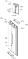
- FIG. 7 is a fourth schematic structural view of a tiling component provided by an embodiment of the present application.
- the mortise and tenon structure 103 includes a mortise 1031 and a tenon 1032.
- the positioning portion 102 is arranged on the tiling side S of the connector 101.
- the mortise 1031 is spaced apart from the positioning portion 102.
- the mortise 1031 is arranged on the connector 101 away from the tiling side S.
- the tenon 1032 is correspondingly inserted into the mortise 1031 and bridging the two connectors 101.
- FIG. 7 illustrates the bridge tenon 1032 arranged on the upper and lower sides of the connector 101 as an example.
- the tenon 1032 may also be provided only on one side of the connector 101.
- the tenon 1032 can be bridged on a side surface of the connector 101 or on a side of the connector 101 away from the tiled display screen, which is not limited here.
- the mortise 1031 is arranged on the connector 101 away from the tiling side S, and the connector 101 can be clamped and fixed at different positions, not limited to the tiling side S.
- the bridging tenon 1031 can connect the connector 101 more firmly.
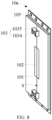
- FIG. 8 is a fifth schematic structural view of a tiling component provided by an embodiment of the present application.
- the mortise and tenon structure 103 includes a protrusion portion 1034 and a fixture portion 1035.
- the protrusion portion 1034 protrudes in a direction perpendicular to a surface of the connector 101.
- the protrusion portion 1034 and the positioning portion 102 both are arranged on the tiling side S of the connector 101.
- the protrusion portion 1034 is spaced apart from the positioning portion 102.
- the protrusion portion 1034 is correspondingly inserted into the fixture portion 1035 to connect two connectors 101.
- the shape of the protrusion portion 1034 illustrated in FIG. 8 is only an example and does not serve as a limitation on the shape of the protrusion portion 1034 in the present application.
- the shape of FIG. 8 can generate the friction force away from the tiling side S on the inclined plane of the protrusion portion 1034 and the fixture portion 1035 to balance the forces that deviate the tiling components 10a from each other. Therefore, it effectively prevents the tiling component 10a from being pulled apart and ensures the tiling stability of the tiling component 10a.
- the mortise and tenon structure 103 includes the protrusion portion 1034 and the fixture portion 1035, with such mortise and tenon structure 103 for fixing, it allows for some error in alignment and reduces the difficulty of alignment and positioning.
- FIG. 9 is a sixth schematic structural view of a tiling component provided by an embodiment of the present application.
- the embodiment shown in FIG. 9 differs from the previous embodiment in that the positioning portion 102 is arranged on the mortise and tenon structure 103.
- the mortise and tenon structure 103 may include a tenon 1031 and a mortise 1032.
- the positioning portion 102 can be provided in the mortise 1032, so that the mortises 1032 can be aligned to form a fixed socket 1033 after the positioning portion 102 is positioned accurately.
- the accuracy of the alignment of the mortise 1032 is increased.
- FIG. 9 illustrates the positioning portion 102 arranged in the mortise 1032 as an example.
- the positioning portion 102 can further be arranged on the protrusion portion 1034, which will not be described in detail here.
- FIG. 10 is a second schematic structural view of a tiled display screen provided by an embodiment of the application.
- a tiled display screen 10 includes a plurality of tiling panel 10b and tiling components 10a.
- the tiling component 10a is the tiling component 10a described in any one of the above embodiments.
- At least one connector 101 is arranged on the tiling side S of a tiling panel 10b.
- Two tiling components 10a are tiled for tiling of the tiling panels 10b.
- the tiling panel 10b includes a back plate 101b and a middle frame 102b arranged around the back plate 101b.
- the tiling panel 10b includes at least one tiling side S.
- the tiling side S may be a side where a edge of the back plate 101b of the tiling panel 10b is tiled.
- the tiling component 10a is arranged on the tiling side S.
- the tiling component 10a is screwed to the backplane 101b with screws 105 through the screw holes formed on the backplane 101b and the tiling component 10a.
- the screw hole plays a positioning role to ensure that the edge of the tiling component 10a does not exceed the edge of the tiling panel 10b.
- the screw hole and the screw 105 play a locking role to fix the tiling component 10a on the tiling panel 10b.
- FIG. 11 is a main structure view of a tiled display screen provided by an embodiment of the application.
- An edge of the tiling component 10a does not exceed an edge of the tiling panel 10b, so that the tiling side S of the tiling panel 10b is not affected by the tiling component 10a during tiling.
- the edge of the tiling component 10a may be flush with the edge of the tiling panel 10b, so as to ensure that the tiling side S does not protrude, so as to minimize the tiling gap during tiling. It is understood that the edge of the tiling component 10a may be slightly indented with respect to the tiling panel 10b.
- an orthographic projection of the tiling component 10a projected on the tiling panel 10b is within an area of the tiling panel 10b.
- the tiling component 10a between adjacent two tiling panels 10b may have a certain gap, but the gap between the mortises 1031 can be filled by designing a tenon 1032 matching a shape of the mortises 1031, which can also ensure the fixing effect of the tenon 1032 and the mortises 1031.
- the shape of the tenon 1032 and filling the gap between the mortise 1031 the contact area between the tenon 1032 and the connector 101 can be increased, so as to obtain a better fixing effect.
- the corresponding tiling component 10a in the adjacent two tiling panels 10b is positioned and tiled through the positioning portion 102 in the tiling component 10a.
- the connector 101 is also provided with a groove 1013.
- the positioning portion 102 is embedded in the groove 1013 so that a surface of the positioning portion 102 is flush with the surface of the connector 101.
- An adhesive layer 1014 is arranged in the groove 1013.
- the positioning portion 102 is fixed in the groove 1013 by the adhesive layer 1014.
- Material of the positioning portion 102 is a magnetic material, and the positioning portion 102 is matching with a shape of the groove 1013.
- the groove 1013 is provided on the connector 101, and then a magnet is embedded in the groove 1013.
- the magnet is fixed and embedded in the groove 1013 through the adhesive layer 1014 so that an edge of the magnet is flush with an edge of the tiling component 10a.
- the two connectors can be fixed through the attraction of the magnets.
- the connectors 101 can play a role in alignment of the connectors 101.
- the magnet is fixed inside the groove 1013 through the adhesive layer 1014 to further fix the magnet. Due to the process accuracy, the magnet may not fully fit with the groove 1013. Configuring the adhesive layer 1014 in the groove can prevent the magnet from peeling off or moving.
- the tiling panel 10b is attracted together by the magnetic attraction of the respective magnets on the tiling component 10a, the magnets play a basic fixing role, and align and position the connectors 101. Then the tenon 1032 with a corresponding shape is placed into the mortise 1031.
- the tiled display screen 10 provided by the embodiment of the application achieves efficient and simple seamless tiling through the tiling component 10a.
- FIG. 12 is a third schematic structural view of a tiled display screen provided by an embodiment of the application.
- a plurality of the tiling components 10a are arranged on a tiling side of each tiling panel 10b, and the tiling components 10a are correspondingly arranged on the tiling sides S of adjacent two of the tiling panels 10b.
- a number of tiling components 10a may be selected according to a size of the tiling panel 10b. In some large-size panels, the length of tiling side S is longer.
- a size of the tiling component 10a does not increase in a proportion. Therefore, increasing a number of the tiling components 10a can prevent the upper and lower ends of tiling components 10a configured on the large-size panels from peeling off.
- the tiling panels 10b can better fix and the efficient tiling of the large-size tiled display screen 10 can be achieved.
- the tiling component 10a is fixed on a tiling surface 10b by a threaded connection.
- the tiling component 10a and the tiling panel 10b are connected by screws 105 and screw holes.
- the screw holes are provided in the back plate 101b of the tiling panel 10b, and then the screw holes play a role in positioning of the tiling component 10a so that the edge of the tiling component 10a does not exceed the edge of the tiling panel 10b.
- the screw 105 has been installed at the screw hole in the figure. Therefore, the screw hole is not shown in the figure.
- the tiling component 10a may further be fixed to the tiling panel 10b by other connection methods, such as gluing.
Landscapes
- Engineering & Computer Science (AREA)
- Microelectronics & Electronic Packaging (AREA)
- Multimedia (AREA)
- Physics & Mathematics (AREA)
- General Physics & Mathematics (AREA)
- Theoretical Computer Science (AREA)
- General Engineering & Computer Science (AREA)
- Mechanical Engineering (AREA)
- Devices For Indicating Variable Information By Combining Individual Elements (AREA)
- Connection Of Plates (AREA)
Abstract
Description
- The application relates to the technical fields of displays, in particular to a tiling component and a tiled display screen.
- With the continuous development of display technologies, displays are used in a wider and wider range of applications, not only for televisions, monitors, industrial displays and medical displays, but also increasingly used in public display occasions. In public display applications, displays are generally required to have a large display area to meet the requirements of people watching from a long distance and displaying larger amounts of information.
- During the research and practice of the conventional art, the inventor of the present application finds that the tiling application of the display screen is usually multi-screen linkage, which requires a large number of display modules, and the bezels of the tiling screens require ultra-narrow bezels, such as the ultra-narrow bezel (UNB) type and extreme narrow bezel (ENB) type, and require no tiling gap visually. Therefore, an efficient tiling structure design is needed to ensure efficient screen installation and a design that reduces the tiling gap.
- The embodiments of the application provide a tiling component and a tiled display screen, which can achieve efficient tiling and reduce the tiling gap.
- The embodiments of the application provide a tiling component, including:
- a connector is provided with a mortise and tenon structure; and
- a positioning portion arranged on the connector; wherein two of the connectors are tiled, the positioning portion is used for positioning the two connectors, and the mortise and tenon structure is used for fixedly connecting the two connectors.
- The tiling component provided by the embodiments of the application positions the connector on a tiling panel through the positioning portion to align the connector. Then, a fixation is achieved by fixing a mortise and tenon structure. As a result, multiple tiling panels are efficiently and seamlessly tiled through the connectors. The tiling component provided in the embodiments of the application improves the installation efficiency of the tiled display screen and simplifies the installation means. Moreover, it is possible to guarantee a seamless design between the tiling display panels.
- Optionally, in some embodiments of the present application, the mortise and tenon structure includes a mortise and a tenon;
- the mortise and the positioning portion both are arranged on a tiling side of the connector, and the mortise and the positioning portion are arranged spaced apart from each other; wherein the mortises in the two connectors are tiled to form a fixed socket; and
- the tenon is correspondingly inserted into the fixed socket to connect the two connectors.
- In the tiling component provided by the embodiments of the application, the mortise and tenon structure includes a mortise and a tenon; The fixation is achieved by inserting the tenon into the mortise in the connector. By configuring the tenon and the mortise with a corresponding shape, the connectors can be firmly connected to avoid separation of the connectors.
- Optionally, in some embodiments of the present application, an opening width of the mortise gradually increases from the tiling side to a direction away from the tiling side.
- In the tiling component provided by the embodiments of the application, when the tiling components generate forces of mutual backwardness, because the opening width on the tiling side is the smallest and gradually increases in a direction away from the tiling side, the inclined planes on the tenon and mortise generate frictions in a direction away from the tiling side to balance the forces that deviate from each other. Therefore, it effectively prevents the tiling component from being pulled apart and ensures the tiling stability of the tiling component.
- Optionally, in some embodiments of the present application, the mortise and tenon structure includes a mortise and a tenon;
- the positioning portion is arranged on a tiling side of the connector, and the mortise and the positioning portion are arranged spaced apart from each other; the mortise is arranged in the connector away from the tiling side, and the tenon is correspondingly inserted into the mortise and bridging the two connectors.
- In the tiling component provided by the embodiments of the application, The mortise is arranged on the connector away from the tiling side, and the connector can be clamped and fixed at different positions, not limited to the tiling side. In addition, the bridging of the tenon can connect the connector more firmly.
- Optionally, in some embodiments of the present application, an opening width of the mortise gradually increases from the tiling side to a direction away from the tiling side.
- In the tiling component provided by the embodiments of the application, when the tiling components generate forces of mutual backwardness, because the opening width on the tiling side is the smallest and gradually increases in a direction away from the tiling side, the inclined planes on the tenon and mortise generate frictions in a direction away from the tiling side to balance the forces that deviate from each other. Therefore, it effectively prevents the tiling component from being pulled apart and ensures the tiling stability of the tiling component.
- Optionally, in some embodiments of the present application, the mortise and tenon structure further includes a protrusion portion and a fixture portion, and the protrusion portion protrudes in a direction perpendicular to a surface of the connector;
- the protrusion portion and the positioning portion both are arranged on a tiling side of the connector, and the protrusion portion and the positioning portion are arranged spaced apart from each other; and
- the protrusion portion is correspondingly inserted into the fixture portion to connect the two connectors.
- In the tiling component provided by the embodiments of the application, with such mortise and tenon structure for fixation, there can be a certain tolerance in alignment and reduce the difficulty of alignment and positioning.
- Optionally, in some embodiments of the present application, a plurality of the mortise and tenon structures are arranged on the connector, and the mortise and tenon structures are arranged on both sides of the positioning portion.
- In the tiling component provided by the embodiments of the application, Configuring the positioning portion in the middle of the connector can make the positioning more accurate. In addition, the mortise and tenon structures are arranged on both sides of the positioning portion, which can make the connector more stable.
- Optionally, in some embodiments of the present application, a plurality of the positioning portions are arranged on the connector, and the positioning portions are arranged on both sides of the mortise and tenon structure.
- In the tiling component provided by the embodiments of the application, configuring a plurality of positioning portions can improve the alignment efficiency of the positioning portion and reduce the alignment error.
- Optionally, in some embodiments of the present application, a plurality of the mortise and tenon structures and a plurality of the positioning portions are arranged on the connector, and the mortise and tenon structures and the positioning portions are arranged alternately.
- In the tiling component provided by the embodiments of the application, Adding the positioning portion can increase the positioning accuracy of the positioning portion and align the connector from multiple angles and directions. Moreover, increasing the number of mortises can strengthen the stability of tiling pieces. Furthermore, alternately configuring a plurality of mortises and a plurality of positioning portions can increase the positioning accuracy of each mortise. Thus, the alignment error of the connector is reduced.
- Optionally, in some embodiments of the present application, the positioning portion is arranged on the mortise and tenon structure.
- In the tiling component provided by the embodiments of the application, the mortise and tenon structure may include a tenon and a mortise. The positioning portion can be provided in the mortise, so that the mortises can be aligned to form a fixed socket after the positioning portion is positioned accurately. Thus, the alignment accuracy of mortises is increased.
- Optionally, in some embodiments of the present application, the connector is further provided with a groove, and the positioning portion is embedded in the groove so that a surface of the positioning portion is flush with a surface of the connector.
- In the tiling component provided by the embodiments of the application, Making the surface of the positioning portion flush with the surface of the connector can ensure the distance between the positioning portions while avoiding protrusions on the tiling side, and ensure the positioning of the positioning portion and the attraction effect. Moreover, it avoids the problem that the positioning portion forms the protrusion on the surface of the connector, which leads to an increase in the tiling gap.
- Optionally, in some embodiments of the present application, an adhesive layer is arranged in the groove, and the positioning portion is fixed in the groove through the adhesive layer.
- In the tiling component provided by the embodiments of the application, configuring a rubber strip in the groove can prevent the magnetic positioning portion from peeling off or moving.
- Optionally, in some embodiments of the present application, material of the positioning portion is a magnetic material, and the positioning portion is matching with a shape of the groove.
- In the tiling component provided by the embodiments of the application, In an aspect, the two connectors can be fixed through the attraction of the magnets. In another aspect, since the magnets on the two pieces are arranged opposite to each other, they can play a role in alignment of the connectors.
- Accordingly, the embodiments of the application provide a tiled display screen, including:
- a plurality tiling panels;
- a tiling component includes a connector and a positioning portion, wherein the connector is provided with a mortise and tenon structure; the positioning portion is arranged on the connector; two of the connectors are tiled, the positioning portion is used for positioning the two connectors, the mortise and tenon structure is used for fixedly connecting the two connectors, at least one connector is arranged on a tiling side of the tiling panel, and two of the tiling components are tiled for the tiling of the tiling panels.
- The tiled display screen provided by the embodiments of the application adopts a tiling component. The tiling component has a connector and a tenon. The connector is provided with a positioning portion and a mortise. A connector on a tiling panel is positioned by a positioning portion, so that the connector is aligned. The fixation is then achieved by inserting the tenon into the mortise in the connector. As a result, multiple tiling panels are efficiently and seamlessly tiled through the connectors. The tiling component provided in the embodiments of the application improves the installation efficiency of the tiled display screen and simplifies the installation means. Moreover, it is possible to guarantee a seamless design between display units.
- Optionally, in some embodiments of the present application, the mortise and tenon structure includes a mortise and a tenon;
- the mortise and the positioning portion both are arranged on a tiling side of the connector, and the mortise and the positioning portion are arranged spaced apart from each other; wherein the mortises in the two connectors are tiled to form a fixed socket; and
- the tenon is correspondingly inserted into the fixed socket to connect the two connectors.
- In the tiled display screen provided by the embodiments of the application, the mortise and tenon structure includes a mortise and a tenon; The fixation is achieved by inserting the tenon into the mortise in the connector. By configuring the tenon and the mortise with a corresponding shape, the connectors can be firmly connected to avoid separation of the connectors.
- Optionally, in some embodiments of the present application, the mortise and tenon structure includes a mortise and a tenon;
the positioning portion is arranged on a tiling side of the connector, and the mortise and the positioning portion are arranged spaced apart from each other; the mortise is arranged in the connector away from the tiling side, and the tenon is correspondingly inserted into the mortise and bridging the two connectors. - In the tiled display screen provided by the embodiments of the application, The mortise is arranged on the connector away from the tiling side, and the connector can be clamped and fixed at different positions, not limited to the tiling side. In addition, the bridging of the tenon can connect the connector more firmly.
- Optionally, in some embodiments of the present application, the mortise and tenon structure further includes a protrusion portion and a fixture portion, and the protrusion portion protrudes in a direction perpendicular to a surface of the connector;
- the protrusion portion and the positioning portion both are arranged on a tiling side of the connector, and the protrusion portion and the positioning portion are arranged spaced apart from each other; and
- the protrusion portion is correspondingly inserted into the fixture portion to connect the two connectors.
- In the tiled display screen provided by the embodiments of the application, with such mortise and tenon structure for fixation, there can be a certain tolerance in alignment and reduce the difficulty of alignment and positioning.
- Optionally, in some embodiments of the present application, an edge of the connector does not exceed an edge of the tiling panel.
- In the tiled display screen provided by the embodiments of the application, An edge of the connector does not exceed an edge of the tiling panel, so that the tiling side of the tiling panel is not affected by the tiling component during tiling, so as to reduce the tiling gap.
- Optionally, in some embodiments of the present application, a plurality of the tiling components are arranged on a tiling side of each tiling panel, and the tiling components are correspondingly arranged on the tiling sides of adjacent two of the tiling panels.
- In the tiled display screen provided by the embodiments of the application, increasing a number of the tiling components can prevent the upper and lower ends of tiling components configured on the large-size panels from peeling off. By adding the tiling components, the tiling panels can better fix and the efficient tiling of the large-size tiled display screen can be achieved.
- Optionally, in some embodiments of the present application, the tiling component is fixed on the tiling panel through a threaded connection.
- In the tiled display screen provided by the embodiments of the application, Positioning the tiling component through the screw hole so that the edge of the tiling component does not exceed the edge of the tiling panel.
- The embodiments of the application provide a tiling component and a tiled display screen. The tiling component has a connector and a tenon. The connector is provided with a positioning portion and a mortise. A connector on a tiling panel is positioned by a positioning portion, so that the connector is aligned. The fixation is then achieved by inserting the tenon into the mortise in the connector. As a result, multiple tiling panels are efficiently and seamlessly tiled through the connectors. The tiling component provided in the embodiments of the application improves the installation efficiency of the tiled display screen and simplifies the installation means. Moreover, it is possible to guarantee a seamless design between display units.
- In order to more clearly explain the technical solutions according to the embodiments of the present application, the following will briefly introduce the drawings that need to be used in the description of the embodiments. It is apparent that the drawings in the following description are only some embodiments of the present application. For those skilled in the art can obtain other drawings based on these drawings without any creative work.
-
FIG. 1 is a first schematic structural view of a tiling component provided by an embodiment of the application. -
FIG. 2 is a first schematic structural view of a tiled display screen provided by an embodiment of the application. -
FIG. 3 is a first schematic enlarged view of A inFIG. 2 . -
FIG. 4 is a second schematic enlarged view of A inFIG. 2 . -
FIG. 5 is a second schematic structural view of a tiling component provided by an embodiment of the application. -
FIG. 6 is a third schematic structural view of a tiling component provided by an embodiment of the application. -
FIG. 7 is a third schematic structural view of a tiling component provided by an embodiment of the application. -
FIG. 8 is a fourth schematic structural view of a tiling component provided by an embodiment of the present application. -
FIG. 9 is a fifth schematic structural view of a tiling component provided by an embodiment of the present application. -
FIG. 10 is a second schematic structural view of a tiled display screen provided by an embodiment of the application. -
FIG. 11 is a main structure view of a tiled display screen provided by an embodiment of the application. -
FIG. 12 is a third schematic structural view of a tiled display screen provided by an embodiment of the present application. - The technical solutions in the embodiments of the present application will be clearly and completely described below in conjunction with the drawings in the embodiments of the present application. It is apparent that the described embodiments are only a part of the embodiments of the present application, rather than all the embodiments. On the basis of the embodiments of the present application, all other embodiments obtained by those skilled in the art without any creative work belong to the protection scope of the present application. In addition, it should be understood that the specific embodiments described herein are only used to illustrate and explain the application and are not used to limit the application. In the present application, in the absence of a contrary explanation, the location terms used herein, such as "above" and "below", usually refer to top and bottom of the device in actual use or working condition, specifically the direction of the accompanying drawings; while "inside" and "outside" are for an outline of the device.
- The embodiments of the application provide a tiling component and a tiled display screen. The following contents are detailed descriptions. It should be noted that the order of description of the following embodiments is not a limitation on the preferred order of the embodiments.
- Referring to
FIG. 1, FIG. 1 is a first schematic structural view of a tiling component provided by an embodiment of the application. As shown inFIG. 1 , atiling component 10a includes aconnector 101 and apositioning portion 102. Theconnector 101 is provided with a mortise andtenon structure 103. Thepositioning portion 102 is arranged on theconnector 101. Twoconnectors 101 are tiled, and thepositioning portions 102 are used to position the twoconnectors 101. The mortise andtenon structure 103 is used to fixedly connect the twoconnectors 101. - The
tiling component 10a provided by the embodiments of the application positions theconnector 101 on a tiling panel through thepositioning portion 102 to align theconnector 101. Then, a fixation is achieved by fixing a mortise andtenon structure 103. As a result, multiple tiling panels are efficiently and seamlessly tiled through theconnectors 101. Thetiling component 10a provided in the embodiments of the application improves the installation efficiency of the tiled display screen and simplifies the installation means. Moreover, it is possible to guarantee a seamless design between the tiling display panels. - Continue referring to
FIG. 1 . The mortise andtenon structure 103 includes amortise 1031 and atenon 1032. The mortise 1011 and thepositioning portion 102 are arranged on a tiling side S of theconnector 101. Themortise 1031 is spaced apart from thepositioning portion 102. Themortises 1031 on the twoconnectors 101 are tiled to form a fixedsocket 1033. thetenon 1032 is correspondingly inserted into the fixedsocket 1033 to connect the twoconnectors 101. - The
tiling component 10a provided in the embodiment of the present application has theconnectors 101 and thetenon 1032. Theconnector 101 is provided with apositioning portion 102 and amortise 1031. Aconnector 101 on a tiling panel is positioned by apositioning portion 102, so that theconnector 101 is aligned. Then, thetenon 1032 is inserted into the fixedsocket 1033 formed by tiling themortises 1031 on theconnectors 101 for fixation. By configuring thetenon 1032 and themortise 1031 with a corresponding shape, theconnectors 101 can be firmly connected to avoid separation of theconnectors 101. - Optionally, the
positioning portion 102 includes a mark positioning portion and a magnetic positioning portion. The mark positioning portion may be a common alignment mark in the display panel. The alignment mark is arranged on the tiling side S of theconnector 101, and then the alignment mark is captured through the camera to align the two connectors. - Referring to
FIG. 2 andFIG. 3 .FIG. 2 is a first schematic structural view of a tiled display screen provided by an embodiment of the application.FIG. 3 is a first schematic enlarged view of A inFIG. 2 . Thetiling component 10a provided in the embodiments of the present application may be applied to atiled display screen 10. As shown inFIG. 2 , thetiled display screen 10 includes a plurality oftiling panel 10b. Thetiling component 10a is used to tile a plurality oftiling panel 10b. InFIG. 2 , in order to illustrate the position of thetiling component 10a on the tiling panel, it only shows onetiling panel 10b as an example. - Optionally, an opening width of the
mortise 1031 gradually increases from the tiling side S to a direction away from the tiling side S. By designing themortise 1031 in this shape, thetiling component 10a can be effectively prevented from being pulled apart. When thetiling components 10a generate forces of mutual backwardness, because the opening width on the tiling side S is the smallest and gradually increases in a direction away from the tiling side S, the inclined planes on thetenon 1032 andmortise 1031 generate frictions to balance the forces that deviate thetiling components 10a from each other. Therefore, it effectively prevents thetiling component 10a from being pulled apart and ensures the tiling stability of thetiling component 10a. - Optionally, the
connector 101 is further provided with agroove 1013. Thepositioning portion 102 is embedded in thegroove 1013 so that a surface of thepositioning portion 102 is flush with the surface of theconnector 101. - As described above, the
positioning portion 102 may be a magnetic positioning portion. The magnetic positioning portion arranged on the surface of theconnector 101 may cause a certain height of protrusion. The protrusions formed by these positioningportions 102 may cause an increased tiling gap. Therefore, in the embodiments of the present application, agroove 1013 is provided on theconnector 101, and thepositioning portion 102 is embedded in thegroove 1013. Thus, the problem of the increased tiling gap caused by the protrusion formed on the surface of theconnector 101 is avoided. In addition, making the surface of thepositioning portion 102 flush with the surface of theconnector 101 can ensure the distance between the positioningportions 102 while avoiding protrusions on the tiling side, and ensure the positioning of thepositioning portion 102 and the attraction effect. - Referring to
figure 4, FIG. 4 is a second schematic enlarged view of A inFIG. 2 . Anadhesive layer 1014 is arranged in thegroove 1013. Thepositioning portion 102 is fixed in thegroove 1013 by theadhesive layer 1014. Due to the process accuracy, thepositioning portion 102 may not fully fit with thegroove 1013. Configuring theadhesive layer 1014 in the groove can prevent thepositioning portion 102 from peeling off or moving. - Optionally, material made of the
positioning portion 102 is a magnetic material. A shape of thepositioning portion 102 matches a shape of thegroove 1013. Specifically, agroove 1013, for example, is provided on theconnector 101, and then a magnet is embedded in thegroove 1013. The magnet is fixed and embedded in thegroove 1013 through theadhesive layer 1014 so that an edge of the magnet is flush with an edge of theconnector 101. Using a magnet as thepositioning portion 102, in an aspect, the two connectors can be fixed through the attraction of the magnets. In another aspect, since the magnets on the twoconnectors 101 are arranged opposite to each other, theconnectors 101 can play a role in alignment of theconnectors 101. - Continue referring to
FIGS. 3 and 4 . Theconnector 101 is provided with a plurality ofmortises 1031. Themortises 1031 are arranged on both sides of thepositioning portion 102. Since the main function of thepositioning portion 102 is to align the adjacent twoconnectors 101 to align themortise 1031, so as to facilitate the subsequent insertion and fixation of the tenon. The fixing effect of thepositioning portion 102 is weaker than that of the mortise and tenon structure. Configuring thepositioning portion 102 in the middle of theconnector 101 can make the positioning more accurate. In addition, the mortise and tenon structures are arranged on both sides of thepositioning portion 102, which can make the connection between the adjacent two connectors more stable. -
FIG. 3 and FIG. 4 illustrate twomortises 1031 as an example. However, the present application does not limit a specific number ofmortises 1031. Specifically, the number ofmortises 1031 can be configured according to a length of theconnector 101. Themortises 1031 may be symmetrically arranged on both sides of thepositioning portion 102. Themortises 1031 may not be symmetrically arranged on both sides of thepositioning portion 102, but only require to provide withmortises 1031 on both sides of thepositioning portion 102. - Referring to
FIG. 5, FIG. 5 is a second schematic structural view of a tiling component provided by an embodiment of the application. Theconnector 101 is provided with a plurality ofpositioning portions 102. The positioningportions 102 are arranged on both sides of themortise 1031. Configuring a plurality ofpositioning portions 102 can improve the alignment efficiency of thepositioning portion 102. When thepositioning portion 102 is a mark positioning portion, the mark is captured by a camera for positioning. When only one marker positioning portion is set, inaccurate positioning may occur due to viewing angle errors. Therefore, configuring multiple positioning portions on theconnector 101 can reduce the alignment error. When thepositioning portion 102 is a magnetic positioning portion, theconnector 101 may shift along a surface of the magnetic positioning portion after the magnets attracting each other. Therefore, by configuring multiple magnetic positioning portions and reducing a surface area of the magnetic positioning portion, the problem of surface shift can be improved and more accurate positioning can be carried out. - Referring to
FIG. 6, FIG. 6 is a third schematic structural view of a tiling component provided by an embodiment of the application. Theconnector 101 is provided withmultiple mortises 1031 andmultiple positioning portions 102, and themortises 1031 and thepositioning portions 102 are arranged alternately. - Adding a number of the
positioning portions 102 can increase the positioning accuracy of thepositioning portion 102 and align theconnector 101 from multiple angles and directions. Moreover, increasing the number of mortises 1012 can strengthen the stability oftiling components 10a. Furthermore, alternately configuring themortises 1031 and thepositioning portions 102 can increase the positioning accuracy of eachmortise 1031. Thus, the alignment error of theconnector 101 reduces. - Referring to
FIG. 7, FIG. 7 is a fourth schematic structural view of a tiling component provided by an embodiment of the present application. The mortise andtenon structure 103 includes amortise 1031 and atenon 1032. Thepositioning portion 102 is arranged on the tiling side S of theconnector 101. Themortise 1031 is spaced apart from thepositioning portion 102. Themortise 1031 is arranged on theconnector 101 away from the tiling side S. Thetenon 1032 is correspondingly inserted into themortise 1031 and bridging the twoconnectors 101. - It should be noted that
FIG. 7 illustrates thebridge tenon 1032 arranged on the upper and lower sides of theconnector 101 as an example. Thetenon 1032 may also be provided only on one side of theconnector 101. In addition, thetenon 1032 can be bridged on a side surface of theconnector 101 or on a side of theconnector 101 away from the tiled display screen, which is not limited here. - The
mortise 1031 is arranged on theconnector 101 away from the tiling side S, and theconnector 101 can be clamped and fixed at different positions, not limited to the tiling side S. In addition, thebridging tenon 1031 can connect theconnector 101 more firmly. - Referring to
FIG. 8, FIG. 8 is a fifth schematic structural view of a tiling component provided by an embodiment of the present application. The mortise andtenon structure 103 includes aprotrusion portion 1034 and afixture portion 1035. Theprotrusion portion 1034 protrudes in a direction perpendicular to a surface of theconnector 101. Theprotrusion portion 1034 and thepositioning portion 102 both are arranged on the tiling side S of theconnector 101. Theprotrusion portion 1034 is spaced apart from thepositioning portion 102. Theprotrusion portion 1034 is correspondingly inserted into thefixture portion 1035 to connect twoconnectors 101. - It should be noted that the shape of the
protrusion portion 1034 illustrated inFIG. 8 is only an example and does not serve as a limitation on the shape of theprotrusion portion 1034 in the present application. The shape ofFIG. 8 can generate the friction force away from the tiling side S on the inclined plane of theprotrusion portion 1034 and thefixture portion 1035 to balance the forces that deviate thetiling components 10a from each other. Therefore, it effectively prevents thetiling component 10a from being pulled apart and ensures the tiling stability of thetiling component 10a. - The mortise and
tenon structure 103 includes theprotrusion portion 1034 and thefixture portion 1035, with such mortise andtenon structure 103 for fixing, it allows for some error in alignment and reduces the difficulty of alignment and positioning. - Referring to
FIG. 9, FIG. 9 is a sixth schematic structural view of a tiling component provided by an embodiment of the present application. The embodiment shown inFIG. 9 differs from the previous embodiment in that thepositioning portion 102 is arranged on the mortise andtenon structure 103. - Optionally, the mortise and
tenon structure 103 may include atenon 1031 and amortise 1032. Thepositioning portion 102 can be provided in themortise 1032, so that themortises 1032 can be aligned to form a fixedsocket 1033 after thepositioning portion 102 is positioned accurately. Thus, the accuracy of the alignment of themortise 1032 is increased. -
FIG. 9 illustrates thepositioning portion 102 arranged in themortise 1032 as an example. Thepositioning portion 102 can further be arranged on theprotrusion portion 1034, which will not be described in detail here. - Accordingly, the embodiment of the present application provides a tiled display screen. Referring to
FIG. 10, FIG. 10 is a second schematic structural view of a tiled display screen provided by an embodiment of the application. Atiled display screen 10 includes a plurality oftiling panel 10b andtiling components 10a. Thetiling component 10a is thetiling component 10a described in any one of the above embodiments. At least oneconnector 101 is arranged on the tiling side S of atiling panel 10b. Twotiling components 10a are tiled for tiling of thetiling panels 10b. - Specifically, the
tiling panel 10b includes aback plate 101b and amiddle frame 102b arranged around theback plate 101b. Thetiling panel 10b includes at least one tiling side S. The tiling side S may be a side where a edge of theback plate 101b of thetiling panel 10b is tiled. Thetiling component 10a is arranged on the tiling side S. On the tiling side S, thetiling component 10a is screwed to thebackplane 101b withscrews 105 through the screw holes formed on thebackplane 101b and thetiling component 10a. In an aspect, the screw hole plays a positioning role to ensure that the edge of thetiling component 10a does not exceed the edge of thetiling panel 10b. In another aspect, the screw hole and thescrew 105 play a locking role to fix thetiling component 10a on thetiling panel 10b. - Referring to
FIG. 11, FIG. 11 is a main structure view of a tiled display screen provided by an embodiment of the application. An edge of thetiling component 10a does not exceed an edge of thetiling panel 10b, so that the tiling side S of thetiling panel 10b is not affected by thetiling component 10a during tiling. Optionally, the edge of thetiling component 10a may be flush with the edge of thetiling panel 10b, so as to ensure that the tiling side S does not protrude, so as to minimize the tiling gap during tiling. It is understood that the edge of thetiling component 10a may be slightly indented with respect to thetiling panel 10b. Namely, an orthographic projection of thetiling component 10a projected on thetiling panel 10b is within an area of thetiling panel 10b. In this case, thetiling component 10a between adjacent twotiling panels 10b may have a certain gap, but the gap between themortises 1031 can be filled by designing atenon 1032 matching a shape of themortises 1031, which can also ensure the fixing effect of thetenon 1032 and themortises 1031. Moreover, by designing the shape of thetenon 1032 and filling the gap between themortise 1031, the contact area between thetenon 1032 and theconnector 101 can be increased, so as to obtain a better fixing effect. - After the
tiling component 10a is configured, thecorresponding tiling component 10a in the adjacent twotiling panels 10b is positioned and tiled through thepositioning portion 102 in thetiling component 10a. - Referring to
FIGS. 4 and11 , theconnector 101 is also provided with agroove 1013. Thepositioning portion 102 is embedded in thegroove 1013 so that a surface of thepositioning portion 102 is flush with the surface of theconnector 101. Anadhesive layer 1014 is arranged in thegroove 1013. Thepositioning portion 102 is fixed in thegroove 1013 by theadhesive layer 1014. Material of thepositioning portion 102 is a magnetic material, and thepositioning portion 102 is matching with a shape of thegroove 1013. - For example, the
groove 1013 is provided on theconnector 101, and then a magnet is embedded in thegroove 1013. The magnet is fixed and embedded in thegroove 1013 through theadhesive layer 1014 so that an edge of the magnet is flush with an edge of thetiling component 10a. Using a magnet as thepositioning portion 102, in an aspect, the two connectors can be fixed through the attraction of the magnets. In another aspect, since the magnets on the twoconnectors 101 are arranged opposite to each other, theconnectors 101 can play a role in alignment of theconnectors 101. - The magnet is fixed inside the
groove 1013 through theadhesive layer 1014 to further fix the magnet. Due to the process accuracy, the magnet may not fully fit with thegroove 1013. Configuring theadhesive layer 1014 in the groove can prevent the magnet from peeling off or moving. - Thus, the
tiling panel 10b is attracted together by the magnetic attraction of the respective magnets on thetiling component 10a, the magnets play a basic fixing role, and align and position theconnectors 101. Then thetenon 1032 with a corresponding shape is placed into themortise 1031. Thetiled display screen 10 provided by the embodiment of the application achieves efficient and simple seamless tiling through thetiling component 10a. - Referring to
FIG. 12, FIG. 12 is a third schematic structural view of a tiled display screen provided by an embodiment of the application. A plurality of thetiling components 10a are arranged on a tiling side of eachtiling panel 10b, and thetiling components 10a are correspondingly arranged on the tiling sides S of adjacent two of thetiling panels 10b. - Specifically, a number of
tiling components 10a may be selected according to a size of thetiling panel 10b. In some large-size panels, the length of tiling side S is longer. When thetiling component 10a is used for tiling, in order to prevent thetiling component 10a from affecting an overall thickness and weight of thetiled display screen 10, a size of thetiling component 10a does not increase in a proportion. Therefore, increasing a number of thetiling components 10a can prevent the upper and lower ends oftiling components 10a configured on the large-size panels from peeling off. By adding thetiling components 10a, thetiling panels 10b can better fix and the efficient tiling of the large-sizetiled display screen 10 can be achieved. - Referring to
FIGS. 3 and12 , optionally, thetiling component 10a is fixed on atiling surface 10b by a threaded connection. For example, thetiling component 10a and thetiling panel 10b are connected byscrews 105 and screw holes. Specifically, the screw holes are provided in theback plate 101b of thetiling panel 10b, and then the screw holes play a role in positioning of thetiling component 10a so that the edge of thetiling component 10a does not exceed the edge of thetiling panel 10b. It can be understood that thescrew 105 has been installed at the screw hole in the figure. Therefore, the screw hole is not shown in the figure. Thetiling component 10a may further be fixed to thetiling panel 10b by other connection methods, such as gluing. - The above description describes a tiling component and a tiled display screen provided by the embodiments of the present application in detail. In this context, specific examples are used to explain the principle and implementation means of the present application. The description of the above embodiments is only used to help understand the methods and core ideas of the present application. Moreover, for those skilled in the art, they may change in the specific implementation means and application scope according to the ideas of the present application. In summary, the content of this specification should not be construed as a limitation to the present application.
Claims (20)
- A tiling component comprising:a connector is provided with a mortise and tenon structure; anda positioning portion arranged on the connector; wherein two of the connectors are tiled, the positioning portion is used for positioning the two connectors, and the mortise and tenon structure is used for fixedly connecting the two connectors.
- The tiling component according to claim 1, wherein the mortise and tenon structure comprises a mortise and a tenon;the mortise and the positioning portion both are arranged on a tiling side of the connector, and the mortise and the positioning portion are arranged spaced apart from each other; wherein the mortises in the two connectors are tiled to form a fixed socket; andthe tenon is correspondingly inserted into the fixed socket to connect the two connectors.
- The tiling component according to claim 2, wherein an opening width of the mortise gradually increases from the tiling side to a direction away from the tiling side.
- The tiling component according to claim 1, wherein the mortise and tenon structure comprises a mortise and a tenon;
the positioning portion is arranged on a tiling side of the connector, and the mortise and the positioning portion are arranged spaced apart from each other; the mortise is arranged in the connector away from the tiling side, and the tenon is correspondingly inserted into the mortise and bridging the two connectors. - The tiling component according to claim 4, wherein an opening width of the mortise gradually increases from the tiling side to a direction away from the tiling side.
- The tiling component according to claim 1, wherein the mortise and tenon structure further comprises a protrusion portion and a fixture portion, and the protrusion portion protrudes in a direction perpendicular to a surface of the connector;the protrusion portion and the positioning portion both are arranged on a tiling side of the connector, and the protrusion portion and the positioning portion are arranged spaced apart from each other; andthe protrusion portion is correspondingly inserted into the fixture portion to connect the two connectors.
- The tiling component according to claim 1, wherein a plurality of the mortise and tenon structures are arranged on the connector, and the mortise and tenon structures are arranged on both sides of the positioning portion.
- The tiling component according to claim 1, wherein a plurality of the positioning portions are arranged on the connector, and the positioning portions are arranged on both sides of the mortise and tenon structure.
- The tiling component according to claim 1, wherein a plurality of the mortise and tenon structures and a plurality of the positioning portions are arranged on the connector, and the mortise and tenon structures and the positioning portions are arranged alternately.
- The tiling component according to claim 1, wherein the positioning portion is arranged on the mortise and tenon structure.
- The tiling component according to claim 1, wherein the connector is further provided with a groove, and the positioning portion is embedded in the groove so that a surface of the positioning portion is flush with a surface of the connector.
- The tiling component according to claim 11, wherein an adhesive layer is arranged in the groove, and the positioning portion is fixed in the groove through the adhesive layer.
- The tiling component according to claim 11, wherein material of the positioning portion is a magnetic material, and the positioning portion is matching with a shape of the groove.
- A tiled display screen comprisingcomprises:a plurality tiling panels;a tiling component comprises a connector and a positioning portion, wherein the connector is provided with a mortise and tenon structure; the positioning portion is arranged on the connector; two of the connectors are tiled, the positioning portion is used for positioning the two connectors, the mortise and tenon structure is used for fixedly connecting the two connectors, at least one connector is arranged on a tiling side of the tiling panel, and two of the tiling components are tiled for the tiling of the tiling panels.
- The tiled display screen according to claim 14, wherein the mortise and tenon structure comprises a mortise and a tenon;the mortise and the positioning portion both are arranged on a tiling side of the connector, and the mortise and the positioning portion are arranged spaced apart from each other; wherein the mortises in the two connectors are tiled to form a fixed socket; andthe tenon is correspondingly inserted into the fixed socket to connect the two connectors.
- The tiled display screen according to claim 14, wherein the mortise and tenon structure comprises a mortise and a tenon;
the positioning portion is arranged on a tiling side of the connector, and the mortise and the positioning portion are arranged spaced apart from each other; the mortise is arranged in the connector away from the tiling side, and the tenon is correspondingly inserted into the mortise and bridging the two connectors. - The tiled display screen according to claim 14, wherein the mortise and tenon structure further comprises a protrusion portion and a fixture portion, and the protrusion portion protrudes in a direction perpendicular to a surface of the connector;the protrusion portion and the positioning portion both are arranged on a tiling side of the connector, and the protrusion portion and the positioning portion are arranged spaced apart from each other; andthe protrusion portion is correspondingly inserted into the fixture portion to connect the two connectors.
- The tiled display screen according to claim 14, wherein an edge of the connector does not exceed an edge of the tiling panel.
- The tiled display screen according to claim 14, wherein a plurality of the tiling components are arranged on a tiling side of each tiling panel, and the tiling components are correspondingly arranged on the tiling sides of adjacent two of the tiling panels.
- The tiled display screen according to claim 14, wherein the tiling component is fixed on the tiling panel through a threaded connection.
Applications Claiming Priority (2)
| Application Number | Priority Date | Filing Date | Title |
|---|---|---|---|
| CN202111501347.0A CN114151425A (en) | 2021-12-09 | 2021-12-09 | Splicing assembly and spliced display screen |
| PCT/CN2021/139629 WO2023103073A1 (en) | 2021-12-09 | 2021-12-20 | Splicing assembly and splicing display screen |
Publications (2)
| Publication Number | Publication Date |
|---|---|
| EP4447027A1 true EP4447027A1 (en) | 2024-10-16 |
| EP4447027A4 EP4447027A4 (en) | 2025-10-15 |
Family
ID=80454229
Family Applications (1)
| Application Number | Title | Priority Date | Filing Date |
|---|---|---|---|
| EP21827169.0A Pending EP4447027A4 (en) | 2021-12-09 | 2021-12-20 | Splice arrangement and splice display screen |
Country Status (5)
| Country | Link |
|---|---|
| US (1) | US12075573B2 (en) |
| EP (1) | EP4447027A4 (en) |
| JP (1) | JP7516431B2 (en) |
| CN (1) | CN114151425A (en) |
| WO (1) | WO2023103073A1 (en) |
Families Citing this family (3)
| Publication number | Priority date | Publication date | Assignee | Title |
|---|---|---|---|---|
| CN115273679A (en) * | 2022-08-20 | 2022-11-01 | 深圳市蓝极星光电科技有限公司 | Splicing connection structure of display screen and flexible LED display screen |
| CN115291427A (en) * | 2022-08-22 | 2022-11-04 | 深圳市松山电子科技有限公司 | Small-size, convenient-to-assemble display screen structure |
| KR20240160423A (en) * | 2023-05-02 | 2024-11-11 | 엘지디스플레이 주식회사 | Display device |
Family Cites Families (22)
| Publication number | Priority date | Publication date | Assignee | Title |
|---|---|---|---|---|
| DE3614490A1 (en) * | 1986-04-29 | 1987-11-05 | Kueffner Reinhold Innenausbau | BASIC FRAME AND CONNECTING ELEMENTS FOR DISPLAY SYSTEMS |
| JP2002290873A (en) | 2001-03-26 | 2002-10-04 | Nec Corp | Method for manufacturing display panel support frame, display panel support frame and display device |
| WO2008147073A1 (en) | 2007-05-29 | 2008-12-04 | Basic Tech Co., Ltd. | Light emitting diode display panel connection apparatus and light emitting diode display apparatus having the same |
| JP2014053367A (en) | 2012-09-05 | 2014-03-20 | Pioneer Electronic Corp | Organic semiconductor device and attachment method of the same |
| US9326620B1 (en) * | 2015-03-12 | 2016-05-03 | Nanolumens Acquisition, Inc. | Modular display system and methods |
| CN206194304U (en) | 2016-08-22 | 2017-05-24 | 厦门市朗星节能照明股份有限公司 | Seamless concatenation formula LED display screen |
| CN205920719U (en) * | 2016-08-22 | 2017-02-01 | 厦门市朗星节能照明股份有限公司 | Pin -connected panel LED display screen |
| CN206400525U (en) * | 2016-11-14 | 2017-08-11 | 广州视源电子科技股份有限公司 | Connecting structure for quickly splicing intelligent flat plate and combined intelligent flat plate device |
| CN110651318B (en) | 2017-03-22 | 2022-06-03 | 10644137 加拿大公司 | Apparatus having flexible LED display module and method employing the same |
| CN207558303U (en) * | 2017-11-17 | 2018-06-29 | 深圳市纽斯达光电有限公司 | A kind of novel high-definition outdoor display screen being easily installed |
| CN107958577A (en) | 2017-12-26 | 2018-04-24 | 深圳市零壹创新科技有限公司 | A kind of spliced alarm set |
| CN208908133U (en) | 2018-09-30 | 2019-05-28 | 广州市安丽电子科技有限公司 | A kind of display screen for leading to driving plate with DP ring being easily installed |
| CN111050098A (en) * | 2018-10-12 | 2020-04-21 | 青岛海尔多媒体有限公司 | Laser television |
| CN209625677U (en) * | 2019-03-22 | 2019-11-12 | 深圳市九晙科技有限公司 | A kind of seamless splicing type LED display |
| CN110827698A (en) * | 2019-11-22 | 2020-02-21 | 盐城盐龙文化体育产业投资有限公司 | Display screen mounting structure capable of being spliced and combined |
| CN212899264U (en) * | 2020-08-26 | 2021-04-06 | 郑州索腾电子科技有限公司 | Concatenation screen convenient to installation |
| CN213331856U (en) * | 2020-09-20 | 2021-06-01 | 广西比佳晟展览有限公司 | Assembling structure of LED display screen |
| CN213635159U (en) | 2020-10-20 | 2021-07-06 | 广州视源电子科技股份有限公司 | Split joint type interactive flat plate |
| CN112419912A (en) | 2020-11-30 | 2021-02-26 | 安徽明洋电子有限公司 | LED display module convenient to assemble |
| CN214175581U (en) * | 2020-12-08 | 2021-09-10 | 广州视源电子科技股份有限公司 | Display screen splicing structure and intelligent interactive panel |
| CN113219729A (en) | 2021-05-10 | 2021-08-06 | 武汉华星光电技术有限公司 | Display panel and display device |
| CN113539125A (en) * | 2021-05-26 | 2021-10-22 | 绍兴汇恒建设管理有限公司 | LED display module and LED display screen |
-
2021
- 2021-12-09 CN CN202111501347.0A patent/CN114151425A/en active Pending
- 2021-12-20 WO PCT/CN2021/139629 patent/WO2023103073A1/en not_active Ceased
- 2021-12-20 JP JP2021577104A patent/JP7516431B2/en active Active
- 2021-12-20 US US17/622,835 patent/US12075573B2/en active Active
- 2021-12-20 EP EP21827169.0A patent/EP4447027A4/en active Pending
Also Published As
| Publication number | Publication date |
|---|---|
| JP7516431B2 (en) | 2024-07-16 |
| EP4447027A4 (en) | 2025-10-15 |
| WO2023103073A1 (en) | 2023-06-15 |
| US20240040710A1 (en) | 2024-02-01 |
| JP2024505602A (en) | 2024-02-07 |
| CN114151425A (en) | 2022-03-08 |
| US12075573B2 (en) | 2024-08-27 |
Similar Documents
| Publication | Publication Date | Title |
|---|---|---|
| US12075573B2 (en) | Tiling component and tiled display screen | |
| US9689563B2 (en) | Angle and alignment adjusting method for a display | |
| CN110544427A (en) | Display main body and splicing intelligent interactive panel | |
| CN116486709A (en) | Video wall | |
| CN210860548U (en) | Reinforcing frame assembly, display main body and spliced intelligent interactive tablet | |
| CN115547203A (en) | Bearing box body assembling part and splicing display device | |
| KR102152708B1 (en) | Video wall and fixing apparatus therefor | |
| US20240114634A1 (en) | Splicing display device | |
| CN214175581U (en) | Display screen splicing structure and intelligent interactive panel | |
| CN201805033U (en) | Coedge connector | |
| CN216053677U (en) | Bearing box body assembling part and splicing display device | |
| EP4372727A1 (en) | Tiled box and tiled display screen | |
| CN222482918U (en) | LED light box, display panel and display device | |
| US20240357752A1 (en) | Display device | |
| CN212381568U (en) | Infrared screen splicing type frame structure without welding | |
| CN216817706U (en) | Frame connection structure and display device | |
| CN110675768A (en) | LED (light-emitting diode) assembling module | |
| US11914240B2 (en) | Spliced display screen | |
| US11920724B2 (en) | Electronic apparatus | |
| CN223743234U (en) | LED cabinets and LED display devices having them | |
| CN110097830A (en) | A kind of complete preceding preceding display screen box body and its display screen safeguarded of installation | |
| CN114399954A (en) | Spliced display panel | |
| KR102410337B1 (en) | Guide pin and video wall using the same | |
| CN115875349B (en) | Display screen splicing mechanism and electronic device | |
| US11922834B2 (en) | Splicing component and spliced display screen |
Legal Events
| Date | Code | Title | Description |
|---|---|---|---|
| STAA | Information on the status of an ep patent application or granted ep patent |
Free format text: STATUS: UNKNOWN |
|
| STAA | Information on the status of an ep patent application or granted ep patent |
Free format text: STATUS: THE INTERNATIONAL PUBLICATION HAS BEEN MADE |
|
| PUAI | Public reference made under article 153(3) epc to a published international application that has entered the european phase |
Free format text: ORIGINAL CODE: 0009012 |
|
| STAA | Information on the status of an ep patent application or granted ep patent |
Free format text: STATUS: REQUEST FOR EXAMINATION WAS MADE |
|
| 17P | Request for examination filed |
Effective date: 20211227 |
|
| AK | Designated contracting states |
Kind code of ref document: A1 Designated state(s): AL AT BE BG CH CY CZ DE DK EE ES FI FR GB GR HR HU IE IS IT LI LT LU LV MC MK MT NL NO PL PT RO RS SE SI SK SM TR |
|
| DAV | Request for validation of the european patent (deleted) | ||
| DAX | Request for extension of the european patent (deleted) | ||
| A4 | Supplementary search report drawn up and despatched |
Effective date: 20250915 |
|
| RIC1 | Information provided on ipc code assigned before grant |
Ipc: G09F 9/302 20060101AFI20250909BHEP Ipc: F16B 5/00 20060101ALI20250909BHEP |