EP4446777A1 - An automotive radar tranceiver system with increased angular separability - Google Patents
An automotive radar tranceiver system with increased angular separability Download PDFInfo
- Publication number
- EP4446777A1 EP4446777A1 EP23167808.7A EP23167808A EP4446777A1 EP 4446777 A1 EP4446777 A1 EP 4446777A1 EP 23167808 A EP23167808 A EP 23167808A EP 4446777 A1 EP4446777 A1 EP 4446777A1
- Authority
- EP
- European Patent Office
- Prior art keywords
- antenna
- subarray
- array antenna
- zero
- antennas
- Prior art date
- Legal status (The legal status is an assumption and is not a legal conclusion. Google has not performed a legal analysis and makes no representation as to the accuracy of the status listed.)
- Pending
Links
Images

Classifications
-
- G—PHYSICS
- G01—MEASURING; TESTING
- G01S—RADIO DIRECTION-FINDING; RADIO NAVIGATION; DETERMINING DISTANCE OR VELOCITY BY USE OF RADIO WAVES; LOCATING OR PRESENCE-DETECTING BY USE OF THE REFLECTION OR RERADIATION OF RADIO WAVES; ANALOGOUS ARRANGEMENTS USING OTHER WAVES
- G01S13/00—Systems using the reflection or reradiation of radio waves, e.g. radar systems; Analogous systems using reflection or reradiation of waves whose nature or wavelength is irrelevant or unspecified
- G01S13/88—Radar or analogous systems specially adapted for specific applications
- G01S13/93—Radar or analogous systems specially adapted for specific applications for anti-collision purposes
- G01S13/931—Radar or analogous systems specially adapted for specific applications for anti-collision purposes of land vehicles
-
- G—PHYSICS
- G01—MEASURING; TESTING
- G01S—RADIO DIRECTION-FINDING; RADIO NAVIGATION; DETERMINING DISTANCE OR VELOCITY BY USE OF RADIO WAVES; LOCATING OR PRESENCE-DETECTING BY USE OF THE REFLECTION OR RERADIATION OF RADIO WAVES; ANALOGOUS ARRANGEMENTS USING OTHER WAVES
- G01S13/00—Systems using the reflection or reradiation of radio waves, e.g. radar systems; Analogous systems using reflection or reradiation of waves whose nature or wavelength is irrelevant or unspecified
- G01S13/02—Systems using reflection of radio waves, e.g. primary radar systems; Analogous systems
- G01S13/06—Systems determining position data of a target
- G01S13/42—Simultaneous measurement of distance and other co-ordinates
-
- G—PHYSICS
- G01—MEASURING; TESTING
- G01S—RADIO DIRECTION-FINDING; RADIO NAVIGATION; DETERMINING DISTANCE OR VELOCITY BY USE OF RADIO WAVES; LOCATING OR PRESENCE-DETECTING BY USE OF THE REFLECTION OR RERADIATION OF RADIO WAVES; ANALOGOUS ARRANGEMENTS USING OTHER WAVES
- G01S13/00—Systems using the reflection or reradiation of radio waves, e.g. radar systems; Analogous systems using reflection or reradiation of waves whose nature or wavelength is irrelevant or unspecified
- G01S13/02—Systems using reflection of radio waves, e.g. primary radar systems; Analogous systems
- G01S13/50—Systems of measurement based on relative movement of target
- G01S13/58—Velocity or trajectory determination systems; Sense-of-movement determination systems
- G01S13/583—Velocity or trajectory determination systems; Sense-of-movement determination systems using transmission of continuous unmodulated waves, amplitude-, frequency-, or phase-modulated waves and based upon the Doppler effect resulting from movement of targets
- G01S13/584—Velocity or trajectory determination systems; Sense-of-movement determination systems using transmission of continuous unmodulated waves, amplitude-, frequency-, or phase-modulated waves and based upon the Doppler effect resulting from movement of targets adapted for simultaneous range and velocity measurements
-
- G—PHYSICS
- G01—MEASURING; TESTING
- G01S—RADIO DIRECTION-FINDING; RADIO NAVIGATION; DETERMINING DISTANCE OR VELOCITY BY USE OF RADIO WAVES; LOCATING OR PRESENCE-DETECTING BY USE OF THE REFLECTION OR RERADIATION OF RADIO WAVES; ANALOGOUS ARRANGEMENTS USING OTHER WAVES
- G01S7/00—Details of systems according to groups G01S13/00, G01S15/00, G01S17/00
- G01S7/02—Details of systems according to groups G01S13/00, G01S15/00, G01S17/00 of systems according to group G01S13/00
- G01S7/03—Details of HF subsystems specially adapted therefor, e.g. common to transmitter and receiver
-
- H—ELECTRICITY
- H01—ELECTRIC ELEMENTS
- H01Q—ANTENNAS, i.e. RADIO AERIALS
- H01Q1/00—Details of, or arrangements associated with, antennas
- H01Q1/27—Adaptation for use in or on movable bodies
- H01Q1/32—Adaptation for use in or on road or rail vehicles
- H01Q1/3208—Adaptation for use in or on road or rail vehicles characterised by the application wherein the antenna is used
- H01Q1/3233—Adaptation for use in or on road or rail vehicles characterised by the application wherein the antenna is used particular used as part of a sensor or in a security system, e.g. for automotive radar, navigation systems
-
- G—PHYSICS
- G01—MEASURING; TESTING
- G01S—RADIO DIRECTION-FINDING; RADIO NAVIGATION; DETERMINING DISTANCE OR VELOCITY BY USE OF RADIO WAVES; LOCATING OR PRESENCE-DETECTING BY USE OF THE REFLECTION OR RERADIATION OF RADIO WAVES; ANALOGOUS ARRANGEMENTS USING OTHER WAVES
- G01S13/00—Systems using the reflection or reradiation of radio waves, e.g. radar systems; Analogous systems using reflection or reradiation of waves whose nature or wavelength is irrelevant or unspecified
- G01S13/02—Systems using reflection of radio waves, e.g. primary radar systems; Analogous systems
- G01S13/06—Systems determining position data of a target
- G01S13/08—Systems for measuring distance only
- G01S13/32—Systems for measuring distance only using transmission of continuous waves, whether amplitude-, frequency-, or phase-modulated, or unmodulated
- G01S13/34—Systems for measuring distance only using transmission of continuous waves, whether amplitude-, frequency-, or phase-modulated, or unmodulated using transmission of continuous, frequency-modulated waves while heterodyning the received signal, or a signal derived therefrom, with a locally-generated signal related to the contemporaneously transmitted signal
- G01S13/343—Systems for measuring distance only using transmission of continuous waves, whether amplitude-, frequency-, or phase-modulated, or unmodulated using transmission of continuous, frequency-modulated waves while heterodyning the received signal, or a signal derived therefrom, with a locally-generated signal related to the contemporaneously transmitted signal using sawtooth modulation
-
- H—ELECTRICITY
- H01—ELECTRIC ELEMENTS
- H01Q—ANTENNAS, i.e. RADIO AERIALS
- H01Q21/00—Antenna arrays or systems
- H01Q21/06—Arrays of individually energised antenna units similarly polarised and spaced apart
- H01Q21/061—Two dimensional planar arrays
Definitions
- the present disclosure relates to automotive radar systems, and in particular to radar systems comprising antenna arrays adapted for detecting the bearing to one or more targets in terms of azimuth and/or elevation angle, in addition to detecting range and radial velocity.
- Automotive radar systems are under constant development. Ever increasing demands on performance metrics such as radar range and angular resolution drives this development. Some modern automotive radar systems are required to be able to separate relatively small objects from each other, such as motorcycles, which are at the same radial range from the radar transceiver and which move with the same radial velocity. This separation of objects requires a radar system which has sufficient performance in terms of azimuth and/or elevation angle separability. A radar system lacking in angle separability performance may not be able to separate two smaller objects from each other, thus risking that higher layer control functions misinterpret the traffic situation, which is undesired.
- the ability to separate targets that are close to each other is very important for automotive sensors, e.g., to realize autonomous driving. This is valid for every domain that a sensor can measure, e.g., Range, Doppler, Azimuth and Elevation for a radar sensor, and becomes more and more important to the angle domain.
- the angular difference that targets can be maximum close together to each other and still be separately seen is called resolution, and an increased resolution in the angle domain is required.
- radar systems based on large antenna arrays can be used, i.e., antenna arrays spanning over a large aperture and comprising a large number of transmit (Tx) and receive (Rx) antenna elements.
- An antenna aperture can be increased by increasing the inter element distance by some factor to improve the angle resolution.
- the bearing spectrum is containing grating lobes that can lead to false targets.
- One way to counteract or at least reduce grating lobes is to have uneven distances between antenna elements.
- Dias discloses a generalized coprime array structure. This can be used to achieve larger aperture with fewer antenna elements.
- a factor can be associated with the coprime numbers and has an option to shift the sub-arrays.
- a linear array antenna comprising at least two superimposed subarray antennas, where each subarray antenna comprises a plurality of antenna elements.
- the shift distance s i is chosen separate from zero and integers, i.e., chosen to be non-zero and non-integer.
- antenna element positions with lower grating lobes and narrow beamwidths leading to more accurate angle estimations.
- By choosing the shift distances in an appropriate manner it can be avoided that antenna elements of the sub-arrays 300, 400 end up on the same position in the resulting linear array antenna 500. This enables more antenna elements to be used in the linear array antenna 500 than presented by prior art.
- the sparsity factor ⁇ i equals 1.
- the compression factor p i equals 1.
- the antenna positions d ni for the linear array antenna are scaled by a scaling factor F that equals A d max , where A denotes a desired antenna aperture and d max denotes the largest value of d ni ⁇ i , i.e., for all the sub-array antennas.
- the determined antenna positions d ni for the linear array antenna can be adapted to fit a certain antenna aperture A.
- FIG. 1A illustrates an example traffic scenario 100 where a vehicle 110 with a radar transceiver arrangement 120 approaches two motorcycles 160, 161.
- the radar transceiver arrangement 120 is associated with a field of view 125.
- This example radar transceiver arrangement 120 is a forward-looking radar.
- the techniques disclosed herein are however not limited to forward looking radar systems but can be used also in corner radars and other types of radar systems.
- the automotive radar transceiver arrangement 120 comprises a radar transceiver 130, an antenna arrangement 140 and a processing device 150.
- the radar transceiver 130 comprises a transmitter device 131 and a receiver device 132
- the antenna arrangement 140 comprises a transmitter antenna arrangement 180 and a receiver antenna arrangement 190.
- the transmitter device 131 and the transmitter antenna arrangement 180 are adapted to generate and transmit radar signals 170, 171.
- the receiver antenna arrangement 190 and the receiver device 132 are adapted to receive the reflected signals 172, 173.
- the processing device 150 is adapted to process the received reflected radar signals 172, 173.
- At least one antenna arrangement 180, 190 comprises at least one linear array antenna 500 as schematically illustrated in Figure 5 , and which in turn comprises a plurality of antenna elements, where adjacent antenna elements are separated by a corresponding distance as will be discussed more in the following.
- the radar transceiver 130 is arranged to generate a frequency modulated continuous wave (FMCW) radar signal over a radar bandwidth called a chirp, where the frequency is swept over the radar bandwidth within a duration.
- FMCW frequency modulated continuous wave
- Other types of radar signal formats may also be used, such as band-spread radar signals where orthogonal codes are used to spread a modulated signal over a wide frequency band, or an orthogonal frequency division multiplexed (OFDM) radar signal.
- OFDM orthogonal frequency division multiplexed
- None of the two motorcycles 160, 161 in the example traffic scenario 100 has a large radar cross section (RCS), and they are located at about the same distance from the radar transceiver arrangement 120.
- the two motorcycles 160, 161 also move with approximately the same radial velocity with respect to the radar transceiver arrangement 120.
- target angles a, b e.g., with respect to a boresight direction 142 in azimuth and or elevation angle.
- a radar transceiver which does not have the required angle separability performance will see the two target objects 160, 161 as a single target.
- a way to obtain an increased angle separability performance is to increase the aperture of the array antenna 140 by increasing the inter element distance by some factor to improve the angle resolution.
- the bearing spectrum contains grating lobes that can lead to false targets.
- a linear array antenna 500 comprising at least two superimposed subarray antennas 300, 400, each subarray antenna 300, 400 comprising a plurality of antenna elements 301, 302, 303, 304; 401, 402, 403, 404, 405.
- the shift distance s i is chosen separate from zero and integers, i.e., chosen to be non-zero and non-integer.
- antenna element positions with lower grating lobes and narrow beamwidths leading to more accurate angle estimations.
- By choosing the shift distances in an appropriate manner it can be avoided that antenna elements of the sub-arrays 300, 400 end up on the same position in the resulting linear array antenna 500. This enables more antenna elements to be used in the linear array antenna 500 than presented by prior art.
- prototype co-prime, uncompressed, array antennas and nested array antennas, fully compressed are special cases and depend on the compression factor p i .
- the sparsity factor ⁇ i equals 1.
- the compression factor p i equals 1.
- the antenna positions d ni for the linear array antenna 500 are scaled by a scaling factor F that equals A d max , where A denotes a desired antenna aperture and d max denotes the largest value of d ni ⁇ i , i.e., for all the sub-array antennas 300, 400.
- the determined antenna positions d ni for the linear array antenna 500 can be adapted to fit a certain antenna aperture A.
- Figure 4 shows a schematic representation of a resulting linear array antenna 500 that is formed by combining the first sub-array antenna 300 and the second sub-array antenna 400.
- a first shift distance s 1 that is non-integer and not zero
- all the antenna elements 301, 302, 303, 304; 401, 402, 403, 404, 405 have different positions d n along the linear array antenna 500.
- the linear array antenna 500 comprises nine individual antenna elements 301, 302, 303, 304; 401, 402, 403, 404, 405.
- the linear array antenna 500 can be scaled to a certain antenna aperture A.
- the present disclosure also relates to a radar transceiver arrangement 120 that comprises a transmitter device 131 and a transmitter antenna arrangement 180 adapted to generate and transmit radar signals 170, 171.
- the radar transceiver arrangement 120 further comprises a receiver device 132 and a receiver antenna arrangement adapted to receive reflected signals 172, 173 which have been reflected by one or more target objects 160, 161.
- At least one antenna arrangement 180, 190 comprises at least one linear array antenna 500 as described herein.
- linear array antenna 500 as described herein can be used for both transmitting antenna arrangements and receiving antenna arrangements, and that several linear array antennas 500, which can be mutually different, can be used to form a two-dimensional array antenna.
- the present disclosure also relates to a two-dimensional array antenna 600 comprising a plurality of linear array antennas 500 1 , 500 2 , 500 3 , ..., 500 z as described herein.
- the number of linear array antennas runs from 1 to z.
- the linear array antennas 500 1 , 500 2 , 500 3 ,..., 500 z are in rows or columns or outer product of linear array antennas 500 i , 500 j to form a two-dimensional array antenna 600 with i , j ⁇ [1, z ].
- outer product at least one of the linear array antennas 500 i , 500 j in question should be co-prime.
- At least two array antennas 500 1 , 500 2 , 500 3 , ..., 500 z comprise antenna elements 301, 302, 303, 304; 401, 402, 403, 404, 405 positioned in mutually different linear manners.
- the present disclosure also relates to a three-dimensional array antenna 700 comprising a plurality of two-dimensional array antennas 600 (only two schematically indicated in Figure 6 ) as described above.
- the present disclosure also relates to a vehicle 110 comprising the radar transceiver arrangement 120 according to the above.
- the present disclosure is not limited to the above, but may vary freely within the scope of the appended claims.
- n i can be an arbitrary number for at least one i.
- tuning parameters can be used to achieve the desired performance. According to some aspects, in practice, a lot of parameters are altered until a desired antenna performance is acquired.
Landscapes
- Engineering & Computer Science (AREA)
- Radar, Positioning & Navigation (AREA)
- Remote Sensing (AREA)
- Physics & Mathematics (AREA)
- Computer Networks & Wireless Communication (AREA)
- General Physics & Mathematics (AREA)
- Computer Security & Cryptography (AREA)
- Electromagnetism (AREA)
- Variable-Direction Aerials And Aerial Arrays (AREA)
- Radar Systems Or Details Thereof (AREA)
Abstract

- the subscript i denotes subarray antenna i (300, 400), where i c [1, q],
- εi is a sparsity factor that can be any positive integer,
-
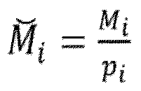

- n is an integer value which indicates the antenna elements (301, 302, 303, 304; 401, 402, 403, 404, 405) and starts from zero,
- dni denotes the position of antenna element n (301, 302, 303, 304; 401, 402, 403, 404, 405) in subarray antenna i (300, 400),
- d is the Nyquist distance, and
- si defines a shift distance from a zero reference, being a real number equal to or larger than zero.
Description
- The present disclosure relates to automotive radar systems, and in particular to radar systems comprising antenna arrays adapted for detecting the bearing to one or more targets in terms of azimuth and/or elevation angle, in addition to detecting range and radial velocity.
- Automotive radar systems are under constant development. Ever increasing demands on performance metrics such as radar range and angular resolution drives this development. Some modern automotive radar systems are required to be able to separate relatively small objects from each other, such as motorcycles, which are at the same radial range from the radar transceiver and which move with the same radial velocity. This separation of objects requires a radar system which has sufficient performance in terms of azimuth and/or elevation angle separability. A radar system lacking in angle separability performance may not be able to separate two smaller objects from each other, thus risking that higher layer control functions misinterpret the traffic situation, which is undesired.
- The ability to separate targets that are close to each other is very important for automotive sensors, e.g., to realize autonomous driving. This is valid for every domain that a sensor can measure, e.g., Range, Doppler, Azimuth and Elevation for a radar sensor, and becomes more and more important to the angle domain. The angular difference that targets can be maximum close together to each other and still be separately seen is called resolution, and an increased resolution in the angle domain is required.
- In order to meet the increasing requirements on angular resolution, radar systems based on large antenna arrays can be used, i.e., antenna arrays spanning over a large aperture and comprising a large number of transmit (Tx) and receive (Rx) antenna elements. An antenna aperture can be increased by increasing the inter element distance by some factor to improve the angle resolution.
- However, if the highest possible frequency is not spatially sampled at least twice, the Nyquist criterion is not fulfilled. In this case the bearing spectrum is containing grating lobes that can lead to false targets. One way to counteract or at least reduce grating lobes is to have uneven distances between antenna elements. The document "Extremely Sparse Co-Prime Sensing: Low Latency Estimation is not a Dream but a Reality", Department of Electrical Engineering, Indian Institute of Technology Delhi, India, 2020, by Usham V. Dias discloses a generalized coprime array structure. This can be used to achieve larger aperture with fewer antenna elements. Here, a factor can be associated with the coprime numbers and has an option to shift the sub-arrays.
- There is, however, a need for improvements to achieve an array antenna with an increased grating lobes reduction and a more efficient use of an antenna aperture.
- This object is at least in part obtained by a linear array antenna comprising at least two superimposed subarray antennas, where each subarray antenna comprises a plurality of antenna elements. For each sub-array antenna i, a plurality of antenna elements are positioned in a linear manner defined by

- Here,
- the subscript i denotes subarray antenna i, with i ∈ [1,q], i.e., i runs from 1 to q and q is the number of subarray antennas,
- ε i is a sparsity factor that can be any positive integer and is used to modify the co-prime locations for the array antenna,
-


- n is an integer value which indicates the antenna elements and starts from zero,
- dni denotes the position of antenna element n in subarray antenna i,
- d is the Nyquist distance,

- si defines a shift distance from a zero reference, being a real number equal to or larger than zero.
- For at least one subarray antenna, the shift distance si is chosen separate from zero and integers, i.e., chosen to be non-zero and non-integer.
- This provides antenna element positions with lower grating lobes and narrow beamwidths, leading to more accurate angle estimations. By choosing the shift distances in an appropriate manner, it can be avoided that antenna elements of the
sub-arrays linear array antenna 500. This enables more antenna elements to be used in thelinear array antenna 500 than presented by prior art. - According to some aspects, for at least one sub-array antenna i, the sparsity factor ε i equals 1. According to some further aspects, for at least one sub-array antenna i, the compression factor pi equals 1.
- In this manner, a simplified expression for the antenna elements is obtained, where the antenna elements are positioned in a linear manner defined by

- According to some aspects, the antenna positions dni for the linear array antenna are scaled by a scaling factor F that equals

- This means that the determined antenna positions dni for the linear array antenna can be adapted to fit a certain antenna aperture A.
- There are also disclosed herein two-dimensional array antennas, three-dimensional array antennas, radar transceiver arrangements and vehicles associated with the above-mentioned advantages.
- Generally, all terms used in the claims are to be interpreted according to their ordinary meaning in the technical field, unless explicitly defined otherwise herein. All references to "a/an/the element, apparatus, component, means, step, etc." are to be interpreted openly as referring to at least one instance of the element, apparatus, component, means, step, etc., unless explicitly stated otherwise. The steps of any method disclosed herein do not have to be performed in the exact order disclosed, unless explicitly stated.
- Further features of, and advantages with, the present invention will become apparent when studying the appended claims and the following description. The skilled person realizes that different features of the present invention may be combined to create embodiments other than those described in the following, without departing from the scope of the present invention.
- The present disclosure will now be described in detail with reference to the appended drawings, where:
-
Figure 1A schematically illustrates a vehicle with a radar sensor; -
Figure 1B schematically illustrates a radar transceiver arrangement; -
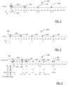
Figure 2 schematically illustrates a first subarray antenna; -
Figure 3 schematically illustrates a second subarray antenna; -
Figure 4 schematically illustrates a linear array antenna that is constituted by the first subarray antenna and the second subarray antenna; -
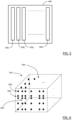
Figure 5 schematically illustrates a two-dimensional array antenna; and -
Figure 6 schematically illustrates a three-dimensional array antenna. - Aspects of the present disclosure will now be described more fully hereinafter with reference to the accompanying drawings. The different arrangements, devices, systems, computer programs and methods disclosed herein can, however, be realized in many different forms and should not be construed as being limited to the aspects set forth herein. Like numbers in the drawings refer to like elements throughout.
- The terminology used herein is for describing aspects of the disclosure only and is not intended to limit the invention. As used herein, the singular forms "a", "an" and "the" are intended to include the plural forms as well, unless the context clearly indicates otherwise.
-
Figure 1A illustrates anexample traffic scenario 100 where avehicle 110 with aradar transceiver arrangement 120 approaches twomotorcycles radar transceiver arrangement 120 is associated with a field ofview 125. This exampleradar transceiver arrangement 120 is a forward-looking radar. The techniques disclosed herein are however not limited to forward looking radar systems but can be used also in corner radars and other types of radar systems. - With reference also to
Figure 1B , according to some aspects, the automotiveradar transceiver arrangement 120 comprises aradar transceiver 130, anantenna arrangement 140 and aprocessing device 150. Theradar transceiver 130 comprises atransmitter device 131 and areceiver device 132, and theantenna arrangement 140 comprises atransmitter antenna arrangement 180 and areceiver antenna arrangement 190. Thetransmitter device 131 and thetransmitter antenna arrangement 180 are adapted to generate and transmitradar signals receiver antenna arrangement 190 and thereceiver device 132 are adapted to receive the reflected signals 172, 173. Theprocessing device 150 is adapted to process the received reflected radar signals 172, 173. - At least one
antenna arrangement linear array antenna 500 as schematically illustrated inFigure 5 , and which in turn comprises a plurality of antenna elements, where adjacent antenna elements are separated by a corresponding distance as will be discussed more in the following. - According to some aspects, the
radar transceiver 130 is arranged to generate a frequency modulated continuous wave (FMCW) radar signal over a radar bandwidth called a chirp, where the frequency is swept over the radar bandwidth within a duration. Other types of radar signal formats may also be used, such as band-spread radar signals where orthogonal codes are used to spread a modulated signal over a wide frequency band, or an orthogonal frequency division multiplexed (OFDM) radar signal. - None of the two
motorcycles example traffic scenario 100 has a large radar cross section (RCS), and they are located at about the same distance from theradar transceiver arrangement 120. The twomotorcycles radar transceiver arrangement 120. Thus, to separate the twotarget objects boresight direction 142 in azimuth and or elevation angle. A radar transceiver which does not have the required angle separability performance will see the twotarget objects - A way to obtain an increased angle separability performance is to increase the aperture of the
array antenna 140 by increasing the inter element distance by some factor to improve the angle resolution. - However, if the highest possible frequency is not sampled at least twice, the Nyquist criterion is not fulfilled. In this case the bearing spectrum contains grating lobes that can lead to false targets.
- In order to counteract the occurrence of grating lobes, with reference to
Figure 2-Figure 4 , there is alinear array antenna 500 comprising at least twosuperimposed subarray antennas subarray antenna antenna elements superimposed subarray antennas - For each sub-array antenna i 300, 400, a plurality of
antenna elements 
- Here,
- the subscript i denotes subarray antenna i 300, 400, with i runs from 1 to q and q is the number of subarray antennas,
- ε i is a sparsity factor that can be any positive integer and is used to modify the co-prime locations for the
array antenna 500, -

- pi is a compression factor that relates to Co-Prime Arrays with Compressed Inter-element Spacings, CACIS, and pi ∈ [1,Mi ], such that

- n is an integer value which indicates the
antenna elements - dni denotes the position of
antenna element n - d is the
Nyquist distance 
- Fi is a scaling factor, and
- si defines a shift distance from a zero reference, being a real number equal to or larger than zero.
- According to the present disclosure, for at least one
subarray antenna 300, the shift distance si is chosen separate from zero and integers, i.e., chosen to be non-zero and non-integer. - This provides antenna element positions with lower grating lobes and narrow beamwidths, leading to more accurate angle estimations. By choosing the shift distances in an appropriate manner, it can be avoided that antenna elements of the sub-arrays 300, 400 end up on the same position in the resulting
linear array antenna 500. This enables more antenna elements to be used in thelinear array antenna 500 than presented by prior art. - According to some aspects, prototype co-prime, uncompressed, array antennas and nested array antennas, fully compressed, are special cases and depend on the compression factor pi .
- According to some aspects, for at least one sub-array antenna i 300, 400, the sparsity factor ε i equals 1.
- According to some aspects, for at least one sub-array antenna i 300, 400, the compression factor pi equals 1.
- This means that the
antenna elements 
- According to some aspects, the antenna positions dni for the
linear array antenna 500 are scaled by a scaling factor F that equals
sub-array antennas - This means that the determined antenna positions dni for the
linear array antenna 500 can be adapted to fit a certain antenna aperture A. - In the following, a non-limiting example where two sub-arrays are determined and combined to form linear array antenna will be described. Here, the sparsity factor ε i equals 1 and the compression factor pi equals 1.
-
Figure 2 shows a schematic representation of a firstsub-array antenna 300, i=1, with M1=5 and where n1 runs from 0 to 3. There is a first shift distance s 1 = 0,4 which means that afirst antenna element 301 on the firstsub-array antenna 300 is shifted 0,4d from a zero reference. All theother antenna elements -
Figure 3 shows a schematic representation of a secondsub-array antenna 400, i=2, with M2=4 and where n2 runs from 0 to 4. There is a second shift distance s 2 = 0 which means that afirst antenna element 401 on the secondsub-array antenna 400 is positioned at the zero reference. All theother antenna elements -
Figure 4 shows a schematic representation of a resultinglinear array antenna 500 that is formed by combining the firstsub-array antenna 300 and the secondsub-array antenna 400. By having a first shift distance s 1 that is non-integer and not zero, all theantenna elements linear array antenna 500. In this manner, thelinear array antenna 500 comprises nineindividual antenna elements - It is also shown how the
linear array antenna 500 can be scaled to a certain antenna aperture A. In this case, the antenna aperture A is a one-dimensional measure that in the example is A=13,98λ and dmax = 16,0d. This leads to that
Figure 4 to provide the scaled antenna element positions dn(F=13,98λ/16d) inFigure 4 . - With renewed reference also to
Figure 1A and Figure 1B , the present disclosure also relates to aradar transceiver arrangement 120 that comprises atransmitter device 131 and atransmitter antenna arrangement 180 adapted to generate and transmitradar signals radar transceiver arrangement 120 further comprises areceiver device 132 and a receiver antenna arrangement adapted to receive reflectedsignals antenna arrangement linear array antenna 500 as described herein. - This means that the
linear array antenna 500 as described herein can be used for both transmitting antenna arrangements and receiving antenna arrangements, and that severallinear array antennas 500, which can be mutually different, can be used to form a two-dimensional array antenna. - With reference to
Figure 5 , the present disclosure also relates to a two-dimensional array antenna 600 comprising a plurality oflinear array antennas - According to some aspects, the
linear array antennas linear array antennas dimensional array antenna 600 with i,j ∈ [1,z]. In the case of outer product, at least one of thelinear array antennas - According to some aspects, at least two
array antennas antenna elements - With reference to
Figure 6 , the present disclosure also relates to a three-dimensional array antenna 700 comprising a plurality of two-dimensional array antennas 600 (only two schematically indicated inFigure 6 ) as described above. - The present disclosure also relates to a
vehicle 110 comprising theradar transceiver arrangement 120 according to the above. The present disclosure is not limited to the above, but may vary freely within the scope of the appended claims. For example, there can be an arbitrary number of antenna elements in each sub-array antenna, i.e., ni can be an arbitrary number for at least one i. - By means of the present disclosure, several tuning parameters can be used to achieve the desired performance. According to some aspects, in practice, a lot of parameters are altered until a desired antenna performance is acquired.
Claims (10)
- A linear array antenna (500) comprising at least two superimposed subarray antennas (300, 400), each subarray antenna (300, 400) comprising a plurality of antenna elements (301, 302, 303, 304; 401, 402, 403, 404, 405), where, for each sub-array antenna i (300, 400), a plurality of antenna elements (301, 302, 303, 304; 401, 402, 403, 404, 405) are positioned in a linear manner defined by
 - the subscript i denotes subarray antenna i (300, 400), with i∈[1,q], i.e., i runs from 1 to q and q is the number of subarray antennas,- ε i is a sparsity factor that can be any positive integer and is used to modify the co-prime locations for the array antenna (500),-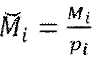
 - n is an integer value which indicates the antenna elements (301, 302, 303, 304; 401, 402, 403, 404, 405) and starts from zero,- dni denotes the position of antenna element n (301, 302, 303, 304; 401, 402, 403, 404, 405) in subarray antenna i (300, 400),- d is the Nyquist distance,
 - si defines a shift distance from a zero reference, being a real number equal to or larger than zero,characterized in that for at least one subarray antenna (300), the shift distance si is chosen separate from zero and integers, i.e., chosen to be non-zero and non-integer.
 - The linear array antenna (500) according to claim 1, wherein, for at least one sub-array antenna i (300, 400), the sparsity factor ε i equals 1.
- The linear array antenna (500) according to any one of the claims 1 or 2, wherein, for at least one sub-array antenna i (300, 400), the compression factor pi equals 1.
- The linear array antenna (500) according to any one of the previous claims, wherein the antenna positions dni for the linear array antenna (500) are scaled by a scaling factor F that equals

- A two-dimensional array antenna (600) comprising a plurality of linear array antennas (5001, 5002, 5003, ..., 500z) according to any one of the previous claims.
- The two-dimensional array antenna (600) according to claim 5, where the linear array antennas (5001, 5002, 5003,..., 500z) are in rows or columns or outer product of linear array antennas (500 i , 500 j ) to form a two-dimensional array antenna (600) with i,j ∈ [1,z].
- The two-dimensional array antenna (600) according to any one of the claims 5 or 6, where at least two array antennas (5001, 5002, 5003, ..., 500z) comprise antenna elements (301, 302, 303, 304; 401, 402, 403, 404, 405) positioned in mutually different linear manners.
- A three-dimensional array antenna (700) comprising a plurality of two-dimensional array antennas (600) according to any one of the claims 5-7.
- A radar transceiver arrangement (120) comprising a transmitter device (131) and a transmitter antenna arrangement (180) adapted to generate and transmit radar signals (170, 171), where the radar transceiver arrangement (120) further comprises a receiver device 132 and a receiver antenna arrangement (190) adapted to receive the reflected signals (172, 173), wherein at least one antenna arrangement (180, 190) comprises at least one linear array antenna (500) according to any one of the previous claims 1-4.
- A vehicle (110) comprising the radar transceiver arrangement (120) according to claim 9.
Priority Applications (3)
| Application Number | Priority Date | Filing Date | Title |
|---|---|---|---|
| EP23167808.7A EP4446777A1 (en) | 2023-04-13 | 2023-04-13 | An automotive radar tranceiver system with increased angular separability |
| PCT/EP2024/060016 WO2024213725A1 (en) | 2023-04-13 | 2024-04-12 | An automotive radar transceiver arrangement and radar array antennas with increased angular separability |
| CN202480025281.8A CN121002400A (en) | 2023-04-13 | 2024-04-12 | Automotive radar transceiver arrangement and radar array antenna with improved angle separability |
Applications Claiming Priority (1)
| Application Number | Priority Date | Filing Date | Title |
|---|---|---|---|
| EP23167808.7A EP4446777A1 (en) | 2023-04-13 | 2023-04-13 | An automotive radar tranceiver system with increased angular separability |
Publications (1)
| Publication Number | Publication Date |
|---|---|
| EP4446777A1 true EP4446777A1 (en) | 2024-10-16 |
Family
ID=86052224
Family Applications (1)
| Application Number | Title | Priority Date | Filing Date |
|---|---|---|---|
| EP23167808.7A Pending EP4446777A1 (en) | 2023-04-13 | 2023-04-13 | An automotive radar tranceiver system with increased angular separability |
Country Status (3)
| Country | Link |
|---|---|
| EP (1) | EP4446777A1 (en) |
| CN (1) | CN121002400A (en) |
| WO (1) | WO2024213725A1 (en) |
Citations (1)
| Publication number | Priority date | Publication date | Assignee | Title |
|---|---|---|---|---|
| EP4050363A1 (en) * | 2021-02-25 | 2022-08-31 | Nxp B.V. | Radar-based detection using sparse array processing |
-
2023
- 2023-04-13 EP EP23167808.7A patent/EP4446777A1/en active Pending
-
2024
- 2024-04-12 CN CN202480025281.8A patent/CN121002400A/en active Pending
- 2024-04-12 WO PCT/EP2024/060016 patent/WO2024213725A1/en not_active Ceased
Patent Citations (1)
| Publication number | Priority date | Publication date | Assignee | Title |
|---|---|---|---|---|
| EP4050363A1 (en) * | 2021-02-25 | 2022-08-31 | Nxp B.V. | Radar-based detection using sparse array processing |
Non-Patent Citations (4)
| Title |
|---|
| QIN SI ET AL: "Generalized Coprime Array Configurations for Direction-of-Arrival Estimation", IEEE TRANSACTIONS ON SIGNAL PROCESSING, IEEE, USA, vol. 63, no. 6, 1 March 2015 (2015-03-01), pages 1377 - 1390, XP011573078, ISSN: 1053-587X, [retrieved on 20150211], DOI: 10.1109/TSP.2015.2393838 * |
| USHAM V DIAS: "Extremely Sparse Co-Prime Sensing: Low Latency Estimation is not a Dream but a Reality", ARXIV.ORG, CORNELL UNIVERSITY LIBRARY, 201 OLIN LIBRARY CORNELL UNIVERSITY ITHACA, NY 14853, 23 November 2020 (2020-11-23), XP081819340 * |
| USHAM V DIAS: "Sub-Nyquist Co-Prime Sensing with Compressed Inter-Element Spacing -- Low Latency Approach", ARXIV.ORG, CORNELL UNIVERSITY LIBRARY, 201 OLIN LIBRARY CORNELL UNIVERSITY ITHACA, NY 14853, 23 July 2020 (2020-07-23), XP081725889 * |
| USHAM V: "Extremely Sparse Co-Prime Sensing: Low Latency Estimation is not a Dream but a Reality", DEPARTMENT OF ELECTRICAL ENGINEERING, INDIAN INSTITUTE OF TECHNOLOGY, 2020 |
Also Published As
| Publication number | Publication date |
|---|---|
| WO2024213725A1 (en) | 2024-10-17 |
| CN121002400A (en) | 2025-11-21 |
Similar Documents
| Publication | Publication Date | Title |
|---|---|---|
| EP1742081B1 (en) | Digital beamforming for an electronically scanned radar system | |
| EP2956795B1 (en) | Multiple-swath stripmap sar imaging | |
| CN108594233B (en) | Speed ambiguity resolving method based on MIMO automobile radar | |
| EP3572838B1 (en) | Radar device | |
| US7994965B2 (en) | Surveillance apparatus and method | |
| US10816641B2 (en) | Imaging radar sensor with synthetic enlargement of the antenna aperture and two-dimensional beam sweep | |
| US4851848A (en) | Frequency agile synthetic aperture radar | |
| WO2018035148A1 (en) | Novel automotive radar using 3d printed luneburg lens | |
| CN101578531A (en) | Electronic scan rader device and receiving array antenna | |
| US5066956A (en) | Azimuth-stacked radar method and apparatus | |
| US12405369B2 (en) | Radar imaging method, and radar implementing such a method | |
| EP4016127A1 (en) | Multiple input multiple steered output (mimso) radar | |
| WO2022229386A1 (en) | Mimo radar using a frequency scanning antenna | |
| US11606151B2 (en) | Array antenna apparatus using spatial power spectrum combining and method of controlling the same | |
| CN116569063A (en) | Motion Compensation for Fast Target Detection in Automotive Radar | |
| US11843162B2 (en) | MIMO radar system for an aerial vehicle | |
| WO2023020959A1 (en) | Low level radar fusion for automotive radar transceivers | |
| Hassanien et al. | Resolving target ambiguities in automotive radar using DDMA techniques | |
| Zhang et al. | Performance analysis of resolving left/right ambiguity in multichannel forward-looking SAR imaging | |
| WO2024213725A1 (en) | An automotive radar transceiver arrangement and radar array antennas with increased angular separability | |
| JP2024022945A (en) | Radar system and radar signal processing method |
Legal Events
| Date | Code | Title | Description |
|---|---|---|---|
| PUAI | Public reference made under article 153(3) epc to a published international application that has entered the european phase |
Free format text: ORIGINAL CODE: 0009012 |
|
| STAA | Information on the status of an ep patent application or granted ep patent |
Free format text: STATUS: THE APPLICATION HAS BEEN PUBLISHED |
|
| AK | Designated contracting states |
Kind code of ref document: A1 Designated state(s): AL AT BE BG CH CY CZ DE DK EE ES FI FR GB GR HR HU IE IS IT LI LT LU LV MC ME MK MT NL NO PL PT RO RS SE SI SK SM TR |
|
| STAA | Information on the status of an ep patent application or granted ep patent |
Free format text: STATUS: REQUEST FOR EXAMINATION WAS MADE |
|
| 17P | Request for examination filed |
Effective date: 20250404 |
|
| GRAP | Despatch of communication of intention to grant a patent |
Free format text: ORIGINAL CODE: EPIDOSNIGR1 |
|
| STAA | Information on the status of an ep patent application or granted ep patent |
Free format text: STATUS: GRANT OF PATENT IS INTENDED |
|
| INTG | Intention to grant announced |
Effective date: 20260216 |
|
| RIC1 | Information provided on ipc code assigned before grant |
Ipc: G01S 13/931 20200101AFI20260206BHEP Ipc: G01S 13/42 20060101ALI20260206BHEP Ipc: G01S 13/58 20060101ALI20260206BHEP Ipc: G01S 7/03 20060101ALI20260206BHEP Ipc: H01Q 1/32 20060101ALI20260206BHEP Ipc: G01S 13/34 20060101ALN20260206BHEP Ipc: H01Q 21/06 20060101ALN20260206BHEP |