EP4446755A1 - Detection of a loose electrical connection in a wind turbine - Google Patents
Detection of a loose electrical connection in a wind turbine Download PDFInfo
- Publication number
- EP4446755A1 EP4446755A1 EP23167272.6A EP23167272A EP4446755A1 EP 4446755 A1 EP4446755 A1 EP 4446755A1 EP 23167272 A EP23167272 A EP 23167272A EP 4446755 A1 EP4446755 A1 EP 4446755A1
- Authority
- EP
- European Patent Office
- Prior art keywords
- conductors
- loops
- coiling
- direction coiling
- measuring wire
- Prior art date
- Legal status (The legal status is an assumption and is not a legal conclusion. Google has not performed a legal analysis and makes no representation as to the accuracy of the status listed.)
- Withdrawn
Links
Images


Classifications
-
- G—PHYSICS
- G01—MEASURING; TESTING
- G01R—MEASURING ELECTRIC VARIABLES; MEASURING MAGNETIC VARIABLES
- G01R19/00—Arrangements for measuring currents or voltages or for indicating presence or sign thereof
- G01R19/165—Indicating that current or voltage is either above or below a predetermined value or within or outside a predetermined range of values
- G01R19/16566—Circuits and arrangements for comparing voltage or current with one or several thresholds and for indicating the result not covered by subgroups G01R19/16504, G01R19/16528, G01R19/16533
- G01R19/16571—Circuits and arrangements for comparing voltage or current with one or several thresholds and for indicating the result not covered by subgroups G01R19/16504, G01R19/16528, G01R19/16533 comparing AC or DC current with one threshold, e.g. load current, over-current, surge current or fault current
-
- G—PHYSICS
- G01—MEASURING; TESTING
- G01R—MEASURING ELECTRIC VARIABLES; MEASURING MAGNETIC VARIABLES
- G01R19/00—Arrangements for measuring currents or voltages or for indicating presence or sign thereof
- G01R19/10—Measuring sum, difference or ratio
-
- F—MECHANICAL ENGINEERING; LIGHTING; HEATING; WEAPONS; BLASTING
- F03—MACHINES OR ENGINES FOR LIQUIDS; WIND, SPRING, OR WEIGHT MOTORS; PRODUCING MECHANICAL POWER OR A REACTIVE PROPULSIVE THRUST, NOT OTHERWISE PROVIDED FOR
- F03D—WIND MOTORS
- F03D17/00—Monitoring or testing of wind motors, e.g. diagnostics
-
- G—PHYSICS
- G01—MEASURING; TESTING
- G01R—MEASURING ELECTRIC VARIABLES; MEASURING MAGNETIC VARIABLES
- G01R15/00—Details of measuring arrangements of the types provided for in groups G01R17/00 - G01R29/00, G01R33/00 - G01R33/26 or G01R35/00
- G01R15/14—Adaptations providing voltage or current isolation, e.g. for high-voltage or high-current networks
- G01R15/18—Adaptations providing voltage or current isolation, e.g. for high-voltage or high-current networks using inductive devices, e.g. transformers
- G01R15/181—Adaptations providing voltage or current isolation, e.g. for high-voltage or high-current networks using inductive devices, e.g. transformers using coils without a magnetic core, e.g. Rogowski coils
-
- G—PHYSICS
- G01—MEASURING; TESTING
- G01R—MEASURING ELECTRIC VARIABLES; MEASURING MAGNETIC VARIABLES
- G01R19/00—Arrangements for measuring currents or voltages or for indicating presence or sign thereof
- G01R19/0092—Measuring current only
-
- G—PHYSICS
- G01—MEASURING; TESTING
- G01R—MEASURING ELECTRIC VARIABLES; MEASURING MAGNETIC VARIABLES
- G01R27/00—Arrangements for measuring resistance, reactance, impedance, or electric characteristics derived therefrom
- G01R27/02—Measuring real or complex resistance, reactance, impedance, or other two-pole characteristics derived therefrom, e.g. time constant
- G01R27/025—Measuring very high resistances, e.g. isolation resistances, i.e. megohm-meters
-
- G—PHYSICS
- G01—MEASURING; TESTING
- G01R—MEASURING ELECTRIC VARIABLES; MEASURING MAGNETIC VARIABLES
- G01R31/00—Arrangements for testing electric properties; Arrangements for locating electric faults; Arrangements for electrical testing characterised by what is being tested not provided for elsewhere
- G01R31/50—Testing of electric apparatus, lines, cables or components for short-circuits, continuity, leakage current or incorrect line connections
- G01R31/52—Testing for short-circuits, leakage current or ground faults
-
- G—PHYSICS
- G01—MEASURING; TESTING
- G01R—MEASURING ELECTRIC VARIABLES; MEASURING MAGNETIC VARIABLES
- G01R31/00—Arrangements for testing electric properties; Arrangements for locating electric faults; Arrangements for electrical testing characterised by what is being tested not provided for elsewhere
- G01R31/50—Testing of electric apparatus, lines, cables or components for short-circuits, continuity, leakage current or incorrect line connections
- G01R31/54—Testing for continuity
-
- G—PHYSICS
- G01—MEASURING; TESTING
- G01R—MEASURING ELECTRIC VARIABLES; MEASURING MAGNETIC VARIABLES
- G01R31/00—Arrangements for testing electric properties; Arrangements for locating electric faults; Arrangements for electrical testing characterised by what is being tested not provided for elsewhere
- G01R31/50—Testing of electric apparatus, lines, cables or components for short-circuits, continuity, leakage current or incorrect line connections
- G01R31/55—Testing for incorrect line connections
-
- G—PHYSICS
- G01—MEASURING; TESTING
- G01R—MEASURING ELECTRIC VARIABLES; MEASURING MAGNETIC VARIABLES
- G01R31/00—Arrangements for testing electric properties; Arrangements for locating electric faults; Arrangements for electrical testing characterised by what is being tested not provided for elsewhere
- G01R31/50—Testing of electric apparatus, lines, cables or components for short-circuits, continuity, leakage current or incorrect line connections
- G01R31/66—Testing of connections, e.g. of plugs or non-disconnectable joints
Definitions
- the invention relates to the detection of a loose connection, or high-resistance connection, of conductors electrically connecting two electrical devices or systems.
- the invention is especially related to electrical devices within wind turbines.
- Wind turbines are positioned either onshore or offshore. In either case, the electrical connections are not checked frequently, often due to the turbines being relatively inaccessible. It thus would be an advantage to have an automatic and/or online detection of a loose connection. This is also the case since due to the loads and conditions, a connection could get loose over time.
- the solution includes introducing a method to measure if there is substantially equal current in a plural of N conductors, the method including to arrange a measuring wire with a first direction coiling formed of N1 loops around a first of the conductors and a second direction coiling formed of N2 loops around a second of the conductors at the opposite looping direction relative to the first direction coiling, wherein number of loops N1 and N2 is selected such that the current induced in the measuring wire due to inductance by the currents in the conductors theoretically adds to value below a threshold T, and detect it as an inequality among the conductors if the added measurement exceeds the threshold T.
- the total sum of loops N1 of the first direction coiling's may be such that it equals the total of sum of loops N2 of the second direction coiling's.
- Each of the first and second direction loops may encircle the same number of conductors.
- Each of the first and second direction loops may encircle a single conductor.
- first direction coiling's There may be double the number of first direction coiling's compared to the number of second direction coiling's, and where the individual of the first direction coiling's has half the number of loops as the individual second direction coiling's.
- Each first kind coiling may comprise two loops, and each second kind coiling comprises four loops.
- the method may be used to detect a loose connection of the conductors.
- the conductors may be divided into groups of three, where for each group the tree conductors are connected with a measuring wire.
- the aggregated number of loops N1 of the first may equal the aggregated number of loops N2 of the second direction coiling's.
- the solution further includes introducing a wind turbine comprising means to control if there is substantially equal current in a plural of N conductors, the means including arrange a measuring wire arranged with a first direction coiling formed of N1 loops around a first of the conductors and a second direction coiling formed of N2 loops around a second of the conductors at the opposite looping direction relative to the first direction coiling, wherein number of loops N1 and N2 is selected such that the current induced in the measuring wire due to inductance by the currents in the conductors theoretically adds to value below a threshold T, and detect it as an inequality among the conductors if the added measurement exceeds the threshold T.
- the wind turbine may include the means for operating according to the method of any of the previous embodiments.
- Figure 1 shows an embodiment wind turbine 1 positioned in the water, such as the ocean.
- the wind turbine 1 comprises a tower 2 mounted on a non-depicted fundament.
- a nacelle 3 is arranged on top of the tower 2.
- the wind turbine 1 further comprises a wind rotor 5 having two, three or more blades 4 (in the perspective of Figure 1 only two blades 4 are visible).
- the wind rotor 5 is rotatable around a longitudinal rotation axis Y.
- the wind turbine 1 comprises an electric generator.
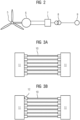
- FIG. 2 schematically shows the principle of construction of the energy producing system of a wind turbine 1 showing a generator 1 connected to the rotor 5 by a shaft or drive train.
- a variable-voltage DC link with a capacitor is feed by the rectified voltage pulses of the generator 1, and an inverter 7, for example a force-commutated inverter, is adapted to create a defined alternating output voltage.
- a transformer 8 brings the alternating voltage to a suitable peak level and frequency for feeding the energy into the utility grid 9.
- Figure 3A illustrates six conductors 10 connecting two devices 11.
- the devices 11 could be any electrical systems or devices where power exchange is required. In one embodiment they could be respectively a generator 6 and inverter 7 in a wind turbine 1, a wind turbine 1 in general to a grid 9, an inverter 7 to the transformer 8 etc.
- the conductors 10 are connected to the devices 11 transferring a total current split between the six conductors 10. Ideally if excluding any effects of current displacement due to asymmetrical magnetic field distribution, each thus will be carrying about the same fraction of the total current in the ideal situation with equal resistivities etc.
- fig. 3A all conductors are correctly connected, but in fig. 3B one is loosely 12 or not fully connected forming a loose or high-resistivity connection. This could form a risk, e.g., the current in the remaining conductors raising to a level where they could be heating possible to start a fire.
- Figure 4 illustrates a method to measure if there is substantially equal current in 3 conductors 10, though the method could be expanded to any number N conductors 10.
- the method includes to arrange a measuring wire 20 with a first direction coiling 30 wrapped around a first of the conductors (10) and a second direction coiling 40 wrapped around a second of the conductors 10 at the opposite looping direction relative to the first direction coiling 30.
- the one of the first 30 and second 40 direction coiling's thus could be looping, or is wrapped, with N1 loops in a clockwise direction around the respective conductor 10, whereas the other of the first 30 and second 40 direction coiling's then could be looping, or is wrapped, with N2 loops in an anti-clockwise direction around the respective conductor 10.
- first direction coiling's 30 are seen each with two loops, and the single second direction coiling 40 are seen with four loops.
- any number N of conductors would apply to the present invention, just as any number of respective first 30 and second 40 direction coiling's.
- the number of loops in the different first direction coiling's 30 and the different second direction coiling's 40 could also be different.
- the number of loops N1, N2 of the respective first 30 and second 40 direction coiling's corresponds to the number of conductors 10 they respectively loop's or is wrapped around.
- the aggregated, or total, number of loops N1 of the first 30 equals the aggregated, or total, number of loops N2 of the second 40 direction coiling's
- the number of loops N1 and N2 is selected such that the current induced in the measuring wire 20 due to inductance by the currents in the conductors 10 theoretically adds to value below a threshold T.
- the method thus includes to detect it as an inequality among the conductors 10) if the added measurement exceeds the threshold T.
- T equals zero or is at least close to zero compared to the expected current of each conductor 10, such as less than 20%, or less than 10% or less than 5%.
- Iw is the current measured in the measuring wire 20
- the parts 2 ⁇ 130,1 and 2 ⁇ I30, 2 is the two first 30 direction coiling's each with two loops and the respective currents I30,1 and I30,2 in the conductors 10.
- the part 4 ⁇ I40 is the four loops of the second direction coiling 40 and the current I40 of the respective conductor 10. If all currents are equal, Iw will be zero, or close to zero. In a less ideal situation if Iw > T, where T is the defined threshold possible being zero, this is an indication of an inequality.
- Figure 5 illustrates an embodiment with more than 3 conductors.
- conductors 10 are seen divided into groups of three. For each group the tree conductors 10 are connected with a measuring wire 20 according to the previous embodiments.
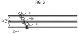
- Figure 6 shows an embodiment where there are more than 3 conductors, where, alternatively, or additionally, to forming groups of three each with a measuring wire 20 as in fig. 3 , all or some of the first 30 and second 40 direction coiling's are wrapped around a plural of conductors 10.
- each of the coiling's 30, 40 loop the same number of conductors 10.
- the number of loops N1, N2 of the respectively first 30 and second 40 direction coiling's are the same as in e.g. fig. 4 , thus giving the same conditions.
- the first part is the sum of the currents I30,n1 of the individual conductors 10 looped by first 30 direction coiling's multiplied with the respective loops N1 n1 .
- the second part is the sum of the currents I40,n1 of the individual conductors 10 looped by second 40 direction coiling's multiplied with the respective loops N2 n2 .
- the respective number loops N1 n1 and N2 n2 of the individual conductors 10 and the number of first 30 and second 40 direction coiling's are then selected such that in case of equality of currents in the conductors 10 the measuring wire 20 current Iw ideally will be zero, or at least close to zero.
- the total sum of loops N1 of the first direction coiling's 30 equals the total of sum of loops N2 of the second direction coiling's 40.
- each of the first 30 and second 40 direction loops encircles the same number of conductors 10.
- the different coiling's 30, 40 loop different number of conductors 10.
Landscapes
- Physics & Mathematics (AREA)
- General Physics & Mathematics (AREA)
- Engineering & Computer Science (AREA)
- Power Engineering (AREA)
- Life Sciences & Earth Sciences (AREA)
- Sustainable Development (AREA)
- Sustainable Energy (AREA)
- Chemical & Material Sciences (AREA)
- Combustion & Propulsion (AREA)
- Mechanical Engineering (AREA)
- General Engineering & Computer Science (AREA)
- Measuring Instrument Details And Bridges, And Automatic Balancing Devices (AREA)
- Testing Of Short-Circuits, Discontinuities, Leakage, Or Incorrect Line Connections (AREA)
- Windings For Motors And Generators (AREA)
Abstract
The related invention relates to a method to measure if there is substantially equal current in a plural of N conductors (10), the method including to arrange a measuring wire (20) with a first direction coiling (30) formed of N1 loops around a first of the conductors (10) and a second direction coiling (40) formed of N2 loops around a second of the conductors (10) at the opposite looping direction relative to the first direction coiling (30), wherein number of loops N1 and N2 is selected such that the current induced in the measuring wire (20) due to inductance by the currents in the conductors (10) theoretically adds to value below a threshold T, and detect it as an inequality among the conductors (10) if the added measurement exceeds the threshold T.
Furthermore, the present invention relates to a wind turbine comprising the means for and operating according to the method.
Description
- The invention relates to the detection of a loose connection, or high-resistance connection, of conductors electrically connecting two electrical devices or systems. The invention is especially related to electrical devices within wind turbines.
- Wind turbines are positioned either onshore or offshore. In either case, the electrical connections are not checked frequently, often due to the turbines being relatively inaccessible. It thus would be an advantage to have an automatic and/or online detection of a loose connection. This is also the case since due to the loads and conditions, a connection could get loose over time.
- It therefore is an object of the present invention to introduce cheap and easily introduced and replicable means and method to identify if there is a loose connection of conductors, which otherwise could lead to damage of the devices or wind turbine itself, such as by fire.
- The object of the invention is achieved by the independent claims. The dependent claims describe advantageous developments and modifications of the invention.
- The solution includes introducing a method to measure if there is substantially equal current in a plural of N conductors, the method including to arrange a measuring wire with a first direction coiling formed of N1 loops around a first of the conductors and a second direction coiling formed of N2 loops around a second of the conductors at the opposite looping direction relative to the first direction coiling, wherein number of loops N1 and N2 is selected such that the current induced in the measuring wire due to inductance by the currents in the conductors theoretically adds to value below a threshold T, and detect it as an inequality among the conductors if the added measurement exceeds the threshold T.
- The total sum of loops N1 of the first direction coiling's may be such that it equals the total of sum of loops N2 of the second direction coiling's.
- Each of the first and second direction loops may encircle the same number of conductors.
- Each of the first and second direction loops may encircle a single conductor.
- There may be double the number of first direction coiling's compared to the number of second direction coiling's, and where the individual of the first direction coiling's has half the number of loops as the individual second direction coiling's.
- There may be two first direction coiling's and one second direction coiling.
- Each first kind coiling may comprise two loops, and each second kind coiling comprises four loops.
- The method may be used to detect a loose connection of the conductors.
- The conductors may be divided into groups of three, where for each group the tree conductors are connected with a measuring wire.
- The aggregated number of loops N1 of the first may equal the aggregated number of loops N2 of the second direction coiling's.
- The solution further includes introducing a wind turbine comprising means to control if there is substantially equal current in a plural of N conductors, the means including arrange a measuring wire arranged with a first direction coiling formed of N1 loops around a first of the conductors and a second direction coiling formed of N2 loops around a second of the conductors at the opposite looping direction relative to the first direction coiling, wherein number of loops N1 and N2 is selected such that the current induced in the measuring wire due to inductance by the currents in the conductors theoretically adds to value below a threshold T, and detect it as an inequality among the conductors if the added measurement exceeds the threshold T.
- The wind turbine may include the means for operating according to the method of any of the previous embodiments.
- Embodiments of the invention are now described, by way of example only, with reference to the accompanying drawings, of which:
- Figure 1
- shows a general illustration of a wind turbine.
- Figure 2
- shows a general illustration of the drive train within a wind turbine.
- Figures 3A
- and B illustrates phase shifted three-phase currents, where
fig. 3A shows the currents adding to zero in an ideal system. - Figure 4
- shows three conductors with a measuring wire formed with first direction coiling's looping two of the conductors, and a second direction coiling looping the third conductor.
- Figure 5
- shows nine conductors divided into groups of three conductors, where for each group a measuring wire is formed with first direction coiling's looping two of the conductors, and a second direction coiling looping the third conductor of the group.
- Figure 6
- shows nine conductors divided into groups of three conductors, where a measuring wire is formed with two first direction coiling's each looping three of the conductors, and a second direction coiling looping the three remaining conductors.
- The illustration in the drawings is in schematic form. It is noted that in different figures, similar or identical elements may be provided with the same reference signs.
-
Figure 1 shows an embodiment wind turbine 1 positioned in the water, such as the ocean. The wind turbine 1 comprises atower 2 mounted on a non-depicted fundament. Anacelle 3 is arranged on top of thetower 2. The wind turbine 1 further comprises awind rotor 5 having two, three or more blades 4 (in the perspective ofFigure 1 only twoblades 4 are visible). Thewind rotor 5 is rotatable around a longitudinal rotation axis Y. The wind turbine 1 comprises an electric generator. -
Figure 2 schematically shows the principle of construction of the energy producing system of a wind turbine 1 showing a generator 1 connected to therotor 5 by a shaft or drive train. A variable-voltage DC link with a capacitor is feed by the rectified voltage pulses of the generator 1, and aninverter 7, for example a force-commutated inverter, is adapted to create a defined alternating output voltage. Atransformer 8 brings the alternating voltage to a suitable peak level and frequency for feeding the energy into the utility grid 9. -
Figure 3A illustrates sixconductors 10 connecting twodevices 11. Thedevices 11 could be any electrical systems or devices where power exchange is required. In one embodiment they could be respectively agenerator 6 and inverter 7 in a wind turbine 1, a wind turbine 1 in general to a grid 9, aninverter 7 to thetransformer 8 etc. - In the illustration six
conductors 10 are illustrated though any number more than oneconductor 10 would apply to the present invention. - In the illustration the
conductors 10 are connected to thedevices 11 transferring a total current split between the sixconductors 10. Ideally if excluding any effects of current displacement due to asymmetrical magnetic field distribution, each thus will be carrying about the same fraction of the total current in the ideal situation with equal resistivities etc. Infig. 3A all conductors are correctly connected, but infig. 3B one is loosely 12 or not fully connected forming a loose or high-resistivity connection. This could form a risk, e.g., the current in the remaining conductors raising to a level where they could be heating possible to start a fire. -
Figure 4 illustrates a method to measure if there is substantially equal current in 3conductors 10, though the method could be expanded to anynumber N conductors 10. - The method includes to arrange a
measuring wire 20 with a first direction coiling 30 wrapped around a first of the conductors (10) and a second direction coiling 40 wrapped around a second of theconductors 10 at the opposite looping direction relative to the first direction coiling 30. The one of the first 30 and second 40 direction coiling's thus could be looping, or is wrapped, with N1 loops in a clockwise direction around therespective conductor 10, whereas the other of the first 30 and second 40 direction coiling's then could be looping, or is wrapped, with N2 loops in an anti-clockwise direction around therespective conductor 10. - In the illustration two first direction coiling's 30 are seen each with two loops, and the single second direction coiling 40 are seen with four loops.
- More generally, any number N of conductors would apply to the present invention, just as any number of respective first 30 and second 40 direction coiling's.
- The number of loops in the different first direction coiling's 30 and the different second direction coiling's 40 could also be different.
- In one embodiment, the number of loops N1, N2 of the respective first 30 and second 40 direction coiling's corresponds to the number of
conductors 10 they respectively loop's or is wrapped around. In the illustrated embodiment offig. 1 the two first direction coiling's 30 each is wrapped around asingle conductor 10 and each comprises N1 = 2 loops. The second direction coiling 40 is wrapped around asingle conductor 10 and each comprises N2 = 4 loops. In total, the aggregated, or total, number of loops N1 of the first 30 equals the aggregated, or total, number of loops N2 of the second 40 direction coiling's - In general, the number of loops N1 and N2 is selected such that the current induced in the
measuring wire 20 due to inductance by the currents in theconductors 10 theoretically adds to value below a threshold T. The method thus includes to detect it as an inequality among the conductors 10) if the added measurement exceeds the threshold T. In one embodiment T equals zero or is at least close to zero compared to the expected current of eachconductor 10, such as less than 20%, or less than 10% or less than 5%. - The equation for the ideal situation taking only account on the currents within the
conductors 10 and their induction of a current in themeasuring wire 20, would then be:
- Where Iw is the current measured in the
measuring wire 20, theparts 2 × 130,1 and 2 × I30, 2 is the two first 30 direction coiling's each with two loops and the respective currents I30,1 and I30,2 in theconductors 10. Thepart 4 × I40 is the four loops of the second direction coiling 40 and the current I40 of therespective conductor 10. If all currents are equal, Iw will be zero, or close to zero. In a less ideal situation if Iw > T, where T is the defined threshold possible being zero, this is an indication of an inequality. -
Figure 5 illustrates an embodiment with more than 3 conductors. In the illustration 9conductors 10 are seen divided into groups of three. For each group thetree conductors 10 are connected with ameasuring wire 20 according to the previous embodiments. -
Figure 6 shows an embodiment where there are more than 3 conductors, where, alternatively, or additionally, to forming groups of three each with ameasuring wire 20 as infig. 3 , all or some of the first 30 and second 40 direction coiling's are wrapped around a plural ofconductors 10. - In
figure 6 each of the coiling's 30, 40 loop the same number ofconductors 10. The number of loops N1, N2 of the respectively first 30 and second 40 direction coiling's are the same as in e.g.fig. 4 , thus giving the same conditions. - A more general equation for the ideal situation taking only account on the currents within the
conductors 10 and their induction of a current in themeasuring wire 20, would then be:
- Where Iw is the current measured in the
measuring wire 20, the first part is the sum of the currents I30,n1 of theindividual conductors 10 looped by first 30 direction coiling's multiplied with the respective loops N1n1. In the same manner, the second part is the sum of the currents I40,n1 of theindividual conductors 10 looped by second 40 direction coiling's multiplied with the respective loops N2n2. - The respective number loops N1n1 and N2n2 of the
individual conductors 10 and the number of first 30 and second 40 direction coiling's are then selected such that in case of equality of currents in theconductors 10 themeasuring wire 20 current Iw ideally will be zero, or at least close to zero. - In the embodiments as illustrated in e.g. any of
figs. 4-6 , the total sum of loops N1 of the first direction coiling's 30 equals the total of sum of loops N2 of the second direction coiling's 40. - Further, for the illustrated embodiments each of the first 30 and second 40 direction loops encircles the same number of
conductors 10. - In some not illustrated embodiments the different coiling's 30, 40 loop different number of
conductors 10.
Claims (12)
- Method to measure if there is substantially equal current in a plural of N conductors (10), the method including to arrange a measuring wire (20) with a first direction coiling (30) formed of N1 loops around a first of the conductors (10) and a second direction coiling (40) formed of N2 loops around a second of the conductors (10) at the opposite looping direction relative to the first direction coiling (30), wherein number of loops N1 and N2 is selected such that the current induced in the measuring wire (20) due to inductance by the currents in the conductors (10) theoretically adds to value below a threshold T, and detect it as an inequality among the conductors (10) if the added measurement exceeds the threshold T.
- Method according to claim 1, wherein the total sum of loops N1 of the first direction coiling's (30) equals the total of sum of loops N2 of the second direction coiling's (40) .
- Method according to claim 1 or 2, wherein each of the first (30) and second (40) direction loops encircles the same number of conductors (10).
- Method according to claim 1, 2 or 3, wherein each of the first (30) and second (40) direction loops encircles a single conductor (10).
- Method according to any of the preceding claims, wherein there are double the number of first direction coiling's (30) compared to the number of second direction coiling's (40), and where the individual of the first direction coiling's (30) has half the number of loops as the individual second direction coiling's (40).
- Method according to claim 5, wherein there are two first direction coiling's (30) and one second direction coiling (40).
- Method according to claim 5 or 6, wherein each first kind coiling (30) comprises two loops, and each second kind coiling (40) comprises four loops.
- Method according to any of the preceding claims, wherein the method is used to detect a loose connection of the conductors (10).
- Method according to any of the preceding claims, wherein the conductors (10) are divided into groups of three, where for each group the tree conductors (10) are connected with a measuring wire (20).
- Method according to any of the preceding claims, the aggregated number of loops N1 of the first 30 equals the aggregated number of loops N2 of the second 40 direction coiling's.
- Wind turbine (1) comprising means to control if there is substantially equal current in a plural of N conductors (10), the means including arrange a measuring wire (20) arranged with a first direction coiling (30) formed of N1 loops around a first of the conductors (10) and a second direction coiling (40) formed of N2 loops around a second of the conductors (10) at the opposite looping direction relative to the first direction coiling (30), wherein number of loops N1 and N2 is selected such that the current induced in the measuring wire (20) due to inductance by the currents in the conductors (10) theoretically adds to value below a threshold T, and detect it as an inequality among the conductors (10) if the added measurement exceeds the threshold T.
- Wind turbine (1) according to claim 11, wherein it includes the means for operating according to the method of any of claims 2-10.
Priority Applications (5)
| Application Number | Priority Date | Filing Date | Title |
|---|---|---|---|
| EP23167272.6A EP4446755A1 (en) | 2023-04-11 | 2023-04-11 | Detection of a loose electrical connection in a wind turbine |
| EP24708208.4A EP4666079A1 (en) | 2023-04-11 | 2024-03-01 | Detection of a loose electrical connection in a wind turbine |
| PCT/EP2024/055410 WO2024213307A1 (en) | 2023-04-11 | 2024-03-01 | Detection of a loose electrical connection in a wind turbine |
| CN202480024770.1A CN120981723A (en) | 2023-04-11 | 2024-03-01 | Detection of loose electrical connections in wind turbines |
| KR1020257033804A KR20250173506A (en) | 2023-04-11 | 2024-03-01 | Detection of loose electrical connections in wind turbines |
Applications Claiming Priority (1)
| Application Number | Priority Date | Filing Date | Title |
|---|---|---|---|
| EP23167272.6A EP4446755A1 (en) | 2023-04-11 | 2023-04-11 | Detection of a loose electrical connection in a wind turbine |
Publications (1)
| Publication Number | Publication Date |
|---|---|
| EP4446755A1 true EP4446755A1 (en) | 2024-10-16 |
Family
ID=85985114
Family Applications (2)
| Application Number | Title | Priority Date | Filing Date |
|---|---|---|---|
| EP23167272.6A Withdrawn EP4446755A1 (en) | 2023-04-11 | 2023-04-11 | Detection of a loose electrical connection in a wind turbine |
| EP24708208.4A Pending EP4666079A1 (en) | 2023-04-11 | 2024-03-01 | Detection of a loose electrical connection in a wind turbine |
Family Applications After (1)
| Application Number | Title | Priority Date | Filing Date |
|---|---|---|---|
| EP24708208.4A Pending EP4666079A1 (en) | 2023-04-11 | 2024-03-01 | Detection of a loose electrical connection in a wind turbine |
Country Status (4)
| Country | Link |
|---|---|
| EP (2) | EP4446755A1 (en) |
| KR (1) | KR20250173506A (en) |
| CN (1) | CN120981723A (en) |
| WO (1) | WO2024213307A1 (en) |
Citations (4)
| Publication number | Priority date | Publication date | Assignee | Title |
|---|---|---|---|---|
| FR2971852A1 (en) * | 2011-02-17 | 2012-08-24 | Neelogy | Method for positioning resilient or flexible magnetic field circulation sensor around e.g. return driver, to measure direct current, circulating in driver, involves positioning sensor according to preset form and specific formula |
| CA2885959A1 (en) * | 2012-10-02 | 2014-04-10 | Wobben Properties Gmbh | Method for monitoring multiple electrical energy lines in a cable strand |
| US20170373625A1 (en) * | 2015-01-13 | 2017-12-28 | Vestas Wind Systems A/S | Monitoring of a dc-link of a split wind-turbine-converter system |
| FR3116125A1 (en) * | 2020-11-09 | 2022-05-13 | Safran Electrical & Power | Current sensor and current sensor transducer assembly system |
-
2023
- 2023-04-11 EP EP23167272.6A patent/EP4446755A1/en not_active Withdrawn
-
2024
- 2024-03-01 EP EP24708208.4A patent/EP4666079A1/en active Pending
- 2024-03-01 CN CN202480024770.1A patent/CN120981723A/en active Pending
- 2024-03-01 WO PCT/EP2024/055410 patent/WO2024213307A1/en not_active Ceased
- 2024-03-01 KR KR1020257033804A patent/KR20250173506A/en active Pending
Patent Citations (4)
| Publication number | Priority date | Publication date | Assignee | Title |
|---|---|---|---|---|
| FR2971852A1 (en) * | 2011-02-17 | 2012-08-24 | Neelogy | Method for positioning resilient or flexible magnetic field circulation sensor around e.g. return driver, to measure direct current, circulating in driver, involves positioning sensor according to preset form and specific formula |
| CA2885959A1 (en) * | 2012-10-02 | 2014-04-10 | Wobben Properties Gmbh | Method for monitoring multiple electrical energy lines in a cable strand |
| US20170373625A1 (en) * | 2015-01-13 | 2017-12-28 | Vestas Wind Systems A/S | Monitoring of a dc-link of a split wind-turbine-converter system |
| FR3116125A1 (en) * | 2020-11-09 | 2022-05-13 | Safran Electrical & Power | Current sensor and current sensor transducer assembly system |
Also Published As
| Publication number | Publication date |
|---|---|
| WO2024213307A1 (en) | 2024-10-17 |
| EP4666079A1 (en) | 2025-12-24 |
| CN120981723A (en) | 2025-11-18 |
| KR20250173506A (en) | 2025-12-10 |
Similar Documents
| Publication | Publication Date | Title |
|---|---|---|
| Polinder et al. | Trends in wind turbine generator systems | |
| EP2241749B1 (en) | An enhanced method of controlling the output of a hydroelectric turbine generator | |
| US8106526B2 (en) | Power converter for use with wind generator | |
| CN103887812B (en) | There is the wind turbine of heterogeneous high-temperature superconducting generator | |
| US9252657B2 (en) | Phase-displacement of a power converter in a wind turbine | |
| EP2114001A1 (en) | A modular converter for converting the electric power produced by aerogenerators, and a wind-power plant that uses said converter | |
| EP3480610B1 (en) | Diagnosing a winding set of a stator | |
| EP3245528B1 (en) | Monitoring of a dc-link of a split wind-turbine-converter system | |
| US20140030089A1 (en) | Wind turbine lifetime estimator | |
| EP2551984A2 (en) | Power plant control system and method for influencing high voltage characteristics | |
| CN102400849A (en) | Frequency conversion wind power equipment | |
| DK3101274T3 (en) | Wind Energy System | |
| Brochu et al. | Generic equivalent collector system parameters for large wind power plants | |
| US20130301167A1 (en) | Transformer arrangement for wind turbine and method for controlling voltage | |
| EP4666079A1 (en) | Detection of a loose electrical connection in a wind turbine | |
| EP3057210A1 (en) | Wind turbine converter | |
| Awad et al. | Mitigation of Temporary Overvoltages in Weak Grids Connected to DFIG-based Wind Farms. | |
| US10141744B2 (en) | Cable arrangement of an energy storage system | |
| Anaya-Lara | Offshore wind farm arrays | |
| US20190097426A1 (en) | Device and method for testing power modules | |
| La Seta et al. | Comparison of stabilizing methods for doubly-fed induction generators for wind turbines | |
| Gheydi et al. | Comparative assessment of power loss among four typical wind turbines in power distribution system | |
| CN114142717B (en) | A fault-tolerant operation control method for wind turbines and wind turbines | |
| Khraijah et al. | Optimization planning for large-scale offshore wind farms using multi-terminal HVDC transmission system | |
| CN224037167U (en) | Coil structure, flat wire stator assembly and generator |
Legal Events
| Date | Code | Title | Description |
|---|---|---|---|
| PUAI | Public reference made under article 153(3) epc to a published international application that has entered the european phase |
Free format text: ORIGINAL CODE: 0009012 |
|
| STAA | Information on the status of an ep patent application or granted ep patent |
Free format text: STATUS: THE APPLICATION HAS BEEN PUBLISHED |
|
| AK | Designated contracting states |
Kind code of ref document: A1 Designated state(s): AL AT BE BG CH CY CZ DE DK EE ES FI FR GB GR HR HU IE IS IT LI LT LU LV MC ME MK MT NL NO PL PT RO RS SE SI SK SM TR |
|
| STAA | Information on the status of an ep patent application or granted ep patent |
Free format text: STATUS: THE APPLICATION IS DEEMED TO BE WITHDRAWN |
|
| 18D | Application deemed to be withdrawn |
Effective date: 20250417 |