EP4446750A1 - Automatic analysis device control method, and automatic analysis device - Google Patents
Automatic analysis device control method, and automatic analysis device Download PDFInfo
- Publication number
- EP4446750A1 EP4446750A1 EP22903841.9A EP22903841A EP4446750A1 EP 4446750 A1 EP4446750 A1 EP 4446750A1 EP 22903841 A EP22903841 A EP 22903841A EP 4446750 A1 EP4446750 A1 EP 4446750A1
- Authority
- EP
- European Patent Office
- Prior art keywords
- flow path
- flow rate
- cleaning
- low
- pressure
- Prior art date
- Legal status (The legal status is an assumption and is not a legal conclusion. Google has not performed a legal analysis and makes no representation as to the accuracy of the status listed.)
- Pending
Links
Images


Classifications
-
- G—PHYSICS
- G01—MEASURING; TESTING
- G01N—INVESTIGATING OR ANALYSING MATERIALS BY DETERMINING THEIR CHEMICAL OR PHYSICAL PROPERTIES
- G01N35/00—Automatic analysis not limited to methods or materials provided for in any single one of groups G01N1/00 - G01N33/00; Handling materials therefor
- G01N35/10—Devices for transferring samples or any liquids to, in, or from, the analysis apparatus, e.g. suction devices, injection devices
-
- G—PHYSICS
- G01—MEASURING; TESTING
- G01N—INVESTIGATING OR ANALYSING MATERIALS BY DETERMINING THEIR CHEMICAL OR PHYSICAL PROPERTIES
- G01N35/00—Automatic analysis not limited to methods or materials provided for in any single one of groups G01N1/00 - G01N33/00; Handling materials therefor
- G01N35/02—Automatic analysis not limited to methods or materials provided for in any single one of groups G01N1/00 - G01N33/00; Handling materials therefor using a plurality of sample containers moved by a conveyor system past one or more treatment or analysis stations
- G01N35/025—Automatic analysis not limited to methods or materials provided for in any single one of groups G01N1/00 - G01N33/00; Handling materials therefor using a plurality of sample containers moved by a conveyor system past one or more treatment or analysis stations having a carousel or turntable for reaction cells or cuvettes
-
- G—PHYSICS
- G01—MEASURING; TESTING
- G01F—MEASURING VOLUME, VOLUME FLOW, MASS FLOW OR LIQUID LEVEL; METERING BY VOLUME
- G01F1/00—Measuring the volume flow or mass flow of fluid or fluent solid material wherein the fluid passes through a meter in a continuous flow
- G01F1/704—Measuring the volume flow or mass flow of fluid or fluent solid material wherein the fluid passes through a meter in a continuous flow using marked regions or existing inhomogeneities within the fluid stream, e.g. statistically occurring variations in a fluid parameter
- G01F1/708—Measuring the time taken to traverse a fixed distance
-
- G—PHYSICS
- G01—MEASURING; TESTING
- G01N—INVESTIGATING OR ANALYSING MATERIALS BY DETERMINING THEIR CHEMICAL OR PHYSICAL PROPERTIES
- G01N35/00—Automatic analysis not limited to methods or materials provided for in any single one of groups G01N1/00 - G01N33/00; Handling materials therefor
- G01N35/00584—Control arrangements for automatic analysers
- G01N35/00594—Quality control, including calibration or testing of components of the analyser
- G01N35/00613—Quality control
- G01N35/00623—Quality control of instruments
-
- G—PHYSICS
- G01—MEASURING; TESTING
- G01N—INVESTIGATING OR ANALYSING MATERIALS BY DETERMINING THEIR CHEMICAL OR PHYSICAL PROPERTIES
- G01N35/00—Automatic analysis not limited to methods or materials provided for in any single one of groups G01N1/00 - G01N33/00; Handling materials therefor
- G01N35/10—Devices for transferring samples or any liquids to, in, or from, the analysis apparatus, e.g. suction devices, injection devices
- G01N35/1004—Cleaning sample transfer devices
-
- G—PHYSICS
- G01—MEASURING; TESTING
- G01N—INVESTIGATING OR ANALYSING MATERIALS BY DETERMINING THEIR CHEMICAL OR PHYSICAL PROPERTIES
- G01N35/00—Automatic analysis not limited to methods or materials provided for in any single one of groups G01N1/00 - G01N33/00; Handling materials therefor
- G01N35/10—Devices for transferring samples or any liquids to, in, or from, the analysis apparatus, e.g. suction devices, injection devices
- G01N35/1009—Characterised by arrangements for controlling the aspiration or dispense of liquids
- G01N35/1016—Control of the volume dispensed or introduced
-
- G—PHYSICS
- G01—MEASURING; TESTING
- G01N—INVESTIGATING OR ANALYSING MATERIALS BY DETERMINING THEIR CHEMICAL OR PHYSICAL PROPERTIES
- G01N35/00—Automatic analysis not limited to methods or materials provided for in any single one of groups G01N1/00 - G01N33/00; Handling materials therefor
- G01N35/10—Devices for transferring samples or any liquids to, in, or from, the analysis apparatus, e.g. suction devices, injection devices
- G01N35/1065—Multiple transfer devices
- G01N35/1072—Multiple transfer devices with provision for selective pipetting of individual channels
-
- G—PHYSICS
- G01—MEASURING; TESTING
- G01N—INVESTIGATING OR ANALYSING MATERIALS BY DETERMINING THEIR CHEMICAL OR PHYSICAL PROPERTIES
- G01N35/00—Automatic analysis not limited to methods or materials provided for in any single one of groups G01N1/00 - G01N33/00; Handling materials therefor
- G01N35/02—Automatic analysis not limited to methods or materials provided for in any single one of groups G01N1/00 - G01N33/00; Handling materials therefor using a plurality of sample containers moved by a conveyor system past one or more treatment or analysis stations
- G01N35/04—Details of the conveyor system
- G01N2035/0401—Sample carriers, cuvettes or reaction vessels
- G01N2035/0437—Cleaning cuvettes or reaction vessels
Definitions
- the present disclosure relates to a control method for an automatic analyzer, and an automatic analyzer.
- An automatic analyzer for example, a biochemical automatic analyzer, analyzes components of a biological sample (hereinafter referred to as a "sample") such as serum or urine.
- a biological sample hereinafter referred to as serum or urine.
- a sample and a reagent are dispensed into a reaction container using a dispensing nozzle and reacted with each other, and a change in color tone or turbidity generated in a reaction solution is optically measured by a photometry unit such as a spectrophotometer. Therefore, contamination or the like of the nozzle affects dispensing accuracy, and as a result, also affects reliability of the automatic analyzer. Therefore, after dispensing a sample or the like, the sample or the like adhering to an outer wall or an inner side of the nozzle is cleaned using a cleaning liquid.
- PTL 1 discloses that "The cleaning liquid circulates around the outside of the probe through the cleaning cell to clean the outside of the probe more thoroughly. Similarly, it is known to cause the cleaning liquid to flow through the probe.
- the cleaning liquid is preferably divided by a plurality of continuous bubbles, and the bubbles are likely to rub against an inner surface of the probe when the bubbles pass through the probe, and further promote removal of a carried substance".
- a flow rate of the cleaning liquid changes.
- a cleaning liquid amount is small, for example, the nozzle cannot be sufficiently cleaned and a carryover or the like may occur.
- a pressure of the flow path is mainly measured to detect an abnormality.
- Such an abnormality detection technique based on pressure measurement is applied to a flow path having a relative high pressure and a high flow rate, and cannot be applied to a flow path having a low pressure and a low flow rate.
- attempts are made to introduce a cleaning system having a low pressure and a low flow rate, but in the related art as in PTL 1, no study is made on detection sensitivity in a cleaning system having a low pressure and a low flow rate.
- the present disclosure proposes a technique for improving detection sensitivity in flow rate measurement in a cleaning system having a low pressure and a low flow rate in an automatic analyzer.
- the present disclosure includes a plurality of methods for solving the above problems, and for example, the present disclosure proposes a control method for an automatic analyzer including a liquid feed pump that feeds, through a flow path, a cleaning liquid to a cleaning mechanism of a dispensing nozzle, and a control unit that controls an operation of the liquid feed pump, in which the control method includes operating, by the control unit, the liquid feed pump to feed the cleaning liquid to a low-pressure flow path having a low pressure and a low flow rate, the low-pressure flow path constituting at least a part of the flow path, and operating, by the control unit, a flow rate estimation mechanism provided in the low-pressure flow path to obtain a flow rate estimation value in the low-pressure flow path.
- detection sensitivity in flow rate measurement in a cleaning system having a low pressure and a low flow rate can be improved in an automatic analyzer.
- the present embodiment discloses a technique of estimating a flow rate in a cleaning system having a low pressure and a low flow rate (for example, an outer cleaning flow path) in an automatic analyzer, detecting a cleaning abnormality based on the estimated flow rate, and adjusting a flow rate of a liquid feed pump.
- a low pressure can be defined as, for example, 10 kPa or less
- a low flow rate can be defined as a flow rate due to liquid feeding at a low pressure (10 kPa).
- a high pressure can be defined as 100 kPa or more.
- FIG. 1 is a diagram showing an overall schematic configuration example of an automatic analyzer 100 according to the present embodiment.
- the automatic analyzer 100 includes a reagent disk 102 on which a plurality of reagent containers 101 are mounted, a reaction disk 103 that mixes a reagent with a sample to measure a reaction, a reagent dispensing mechanism 104 that aspirates and discharges a reagent, a sample dispensing mechanism 105 that aspirates and discharges a sample, and a control unit (a processor) 214 that controls opening and closing of a liquid feed pump 202 and valves (see FIG. 2 ).
- the automatic analyzer 100 may include other components.
- the reagent dispensing mechanism 104 includes a reagent nozzle (not shown) for dispensing a reagent.
- the sample dispensing mechanism 105 includes a sample dispensing nozzle 110 for dispensing a sample.
- a sample loaded into the automatic analyzer is loaded into a sample container (a test tube) 108 and is transported by being mounted on a rack 106.
- a plurality of sample containers 108 are mounted on the rack 106.
- the sample is urine or a sample derived from blood such as serum or whole blood.
- the sample dispensing mechanism 105 moves, by a rotation operation, the sample dispensing nozzle 110 to an aspiration position at which a sample is aspirated from the sample container 108, a discharge position at which the sample is discharged to a cell 109, and a cleaning position at which a tip end of the sample dispensing nozzle 110 is cleaned in a cleaning tank 107.
- sample dispensing mechanism 105 lowers the sample dispensing nozzle 110 according to heights of the sample container 108, the cell 109, and the cleaning tank 107 at the aspiration position, the discharge position, and the cleaning position.
- the sample dispensing nozzle 110 and the reagent nozzle are provided with a liquid contact detection sensor for detecting a liquid surface, and contacting with a target liquid (a sample or a reagent) can be confirmed based on a sensor signal.
- the automatic analyzer 100 measures a mixed liquid of a sample and a reagent contained in the cell 109 to analyze a concentration of a predetermined component in the sample.
- a general configuration of the automatic analyzer 100 is described above.
- the technique according to the present embodiment can also be applied to a case of a reagent nozzle in which the same nozzle is cleaned and repeatedly used.
- the present embodiment is also applicable to an apparatus for dispensing a sample and a reagent using the same nozzle.
- FIG. 2 is a diagram showing a schematic configuration example of a cleaning flow path of a dispensing mechanism (the sample dispensing mechanism 105) in the automatic analyzer 100 according to the present embodiment.
- a cleaning system flow path of the automatic analyzer 100 includes, for example, an inner cleaning flow path 206 and an outer cleaning flow path 207, and is implemented by a cleaning liquid storage container 201, the liquid feed pump 202 that feeds a cleaning liquid, the cleaning tank 107 for cleaning an outer wall of a nozzle, a sample syringe 203 for aspirating and discharging a sample, the sample dispensing nozzle (hereinafter, simply referred to as a dispensing nozzle) 110, a three-way electromagnetic valve 204 provided downstream of the liquid feed pump 202, and a three-way electromagnetic valve 208 provided upstream of the dispensing nozzle 110.
- the three-way electromagnetic valve 204 selectively connects the inner cleaning flow path 206 for supplying a cleaning liquid into the dispensing nozzle 110 and the outer cleaning flow path 207 for supplying the cleaning liquid to the cleaning tank 107 for cleaning an outer wall of the dispensing nozzle 110 to a cleaning liquid supply flow path 205 for feeding the cleaning liquid by the liquid feed pump 202.
- the three-way electromagnetic valve 208 switches a connection source of the dispensing nozzle 110.
- the cleaning liquid can be supplied to the dispensing nozzle 110 to clean the inside of the dispensing nozzle 110.
- a sample can be aspirated or discharged using the sample syringe 203.
- the sample syringe 203 and the dispensing flow path 209 are filled with degassed water supplied through a two-way electromagnetic valve 210.
- a bubble generation unit implemented by a three-way electromagnetic valve 211 is provided at a predetermined position (upstream) of the outer cleaning flow path 207, and a bubble sensor 212 and a bubble sensor 213 are disposed at a constant interval downstream of the three-way electromagnetic valve 211.
- Bubbles (air) can be introduced into the outer cleaning flow path 207 through the three-way electromagnetic valve 211 (by opening an atmospheric relief valve NC), and the bubbles (a boundary surface between the cleaning liquid and air) are detected by the bubble sensors.
- the outer cleaning flow path 207 is a flow path that operates at a low pressure (for example, 10 kPa or less as described above) and a low flow rate, bubbles are less likely to collapse when the bubbles (air) are introduced into the outer cleaning flow path 207, and detection becomes easy. It is possible to avoid a risk of deteriorating dispensing accuracy due to bubbles mixing into the sample syringe 203.
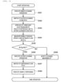
- FIG. 3 is a flowchart showing dispensing operation control processing according to the present embodiment.
- the dispensing operation includes an inner cleaning operation, an outer cleaning operation, and a sample dispensing operation, and in the present embodiment, a flow rate of the liquid feed pump 202. is estimated during the outer cleaning operation.
- control unit 214 operates the liquid feed pump 202 to supply the cleaning liquid from the cleaning liquid storage container 201 to the inner cleaning flow path 206 through the cleaning liquid supply flow path 205, and performs inner cleaning for the dispensing nozzle 110.
- the control unit 214 switches the three-way electromagnetic valve 204 to connect the cleaning liquid supply flow path 205 to the outer cleaning flow path 207.
- the control unit 214 operates the liquid feed pump 202 to fill the outer cleaning flow path 207 (for example, a flow path up to the cleaning tank 107) with the cleaning liquid.
- the control unit 214 switches the three-way electromagnetic valve 211 that is a bubble generation unit to an atmospheric relief side for a certain time. During this time, the cleaning liquid inside the outer cleaning flow path 207 is discharged from the cleaning tank 107 due to falling under own weight of the cleaning liquid.
- control unit 214 returns the three-way electromagnetic valve 211 to a closed state and causes the liquid feed pump 202 to feed the cleaning liquid. Then, a boundary surface between the cleaning liquid and air (may be a boundary surface between the cleaning liquid and air in a bubble) moves in the outer cleaning flow path.
- the control unit 214 obtains a time difference between a time at which the boundary surface between the cleaning liquid and air passes through the bubble sensor 212 and a time at which the boundary surface between the cleaning liquid and air passes through the bubble sensor 213, and calculates a bubble moving speed V (the number of bubble sensors may be one).
- the control unit 214 compares the estimated flow rate Q with a preset target flow rate Q 0 to determine whether the estimated flow rate Q is within a normal range. Specifically, it is determined whether
- ⁇ ⁇ Q YES in step 305: the flow rate is within the normal range
- the processing proceeds to step 306.
- ⁇ ⁇ Q NO in step 305: the flow rate is out of the normal range
- the processing proceeds to step 309.
- the control unit 214 operates the liquid feed pump 202 to supply the cleaning liquid to the outer cleaning flow path 207, and performs outer cleaning for the dispensing nozzle 110.
- the outer cleaning can be performed by spraying the cleaning liquid to a tip end of the dispensing nozzle 110 in the cleaning tank 107.
- the control unit 214 controls the three-way electromagnetic valve 208 to close a cleaning liquid supply side and open a sample liquid supply side, thereby switching to a dispensing flow path.
- the control unit 214 moves the dispensing nozzle 110 to the sample container 108 and performs a dispensing operation. When the dispensing operation is completed, the processing is ended.
- the control unit 214 notifies of a cleaning abnormality (for example, notification by voice or notification by displaying a warning message on a display screen), and ends the processing without performing the dispensing operation.
- a cleaning abnormality for example, notification by voice or notification by displaying a warning message on a display screen
- FIG. 4 is a flowchart showing the flow rate adjustment processing according to the present embodiment.
- the control unit 214 performs the same operations as those in steps 303 and 304, measures a moving speed V of bubbles (a boundary surface between the cleaning liquid and air), and calculates the estimated flow rate Q.
- step 401 may not be executed. In this case, a value of the estimated flow rate Q calculated in step 304 can be used.
- control unit 214 performs the same operations as those in steps 303 and 304, measures a moving speed V of bubbles (a boundary surface between the cleaning liquid and air), and calculates the estimated flow rate. Q.
- the control unit 214 compares the estimated flow rate Q with the preset target flow rate Q 0 to determine whether the estimated flow rate Q is within a normal range. Specifically, it is determined whether
- ⁇ ⁇ Q YES in step 404: the flow rate is within the normal range
- the flow rate adjustment processing is ended.
- ⁇ ⁇ Q NO in step 404: the flow rate is out of the normal range
- the processing proceeds to step 405.
- the control unit 214 notifies of a cleaning abnormality (for example, notification by voice or notification by displaying a warning message on a display screen), and ends the processing without performing the dispensing operation.
- a cleaning abnormality for example, notification by voice or notification by displaying a warning message on a display screen
- the processing may proceed to step 402 without notifying the cleaning abnormality, and a pump drive voltage adjustment may be performed until the difference between the estimated flow rate Q and the target flow rate Q 0 is less than the flow rate error allowable range ⁇ Q (loop processing from step 402 to step 404).
- the technique according to the present disclosure is not limited to the above-described embodiment, and includes various modifications.
- the above-described embodiment has been described in detail to facilitate understanding of the technique according to the present disclosure, and is not necessarily limited to those including all the configurations described above.
- a part of a configuration according to one embodiment can be replaced with a configuration according to another embodiment, and other components can be added to components according to the present embodiment.
- another configuration can be added to, deleted from, or replaced with a part of configurations according to one embodiment.
- modifications will be exemplified.
- the flow rate abnormality determination processing and the flow rate adjustment processing based on a flow rate (an inner cleaning flow rate) of the outer cleaning flow path 207 are described. However, depending on conditions (for example, when a flow rate of the inner cleaning flow path 206 (an inner cleaning flow rate) is more important than the outer cleaning flow rate or when it is desired to control the inner cleaning flow rate), it may, be necessary to determine a flow rate abnormality or adjust a flow rate based on the inner cleaning flow rate.
- a correlation coefficient k Q A /Q B between the inner cleaning flow path flow rate Q A and the outer cleaning flow path flow rate Q B is obtained using a flowmeter or the like, and is stored in an internal memory (not shown) of the control unit 214.
- a configuration can be adopted in which flow rate estimation mechanisms are collectively disposed at one place of the cleaning liquid supply flow path 205 most upstream of a cleaning flow path, and the above-described flow rate estimation processing can be applied to such a configuration.
- the dispensing mechanisms and cleaning mechanisms can be reduced in size by the plurality of flow rate estimation mechanisms at one place.
- a configuration can be adopted in which flow rate estimation mechanisms are collectively disposed at one place of a waste liquid tank (not shown) connected to the cleaning tank 107 most downstream of a cleaning flow path, and the above-described flow rate estimation processing can be applied to such a configuration.
- the dispensing mechanisms and cleaning mechanisms can be reduced in size by collecting the plurality of flow rate estimation mechanisms at one place.
- control unit 214 may be divided and executed by a plurality of control units.
- the plurality of control units may be incorporated in the automatic analyzer 100 or may be provided outside of the automatic analyzer 100.
- a flow rate in the outer cleaning flow path 207 may be estimated by a thermal flowmeter including a heater and a temperature sensor or a Coriolis flowmeter using a Coriolis force.
- An operating system (OS) or the like operating on a computer may perform a part or all of actual processing based on an instruction of the program code, and the functions of the above-described embodiment may be implemented by the processing. Further, after the program code read from the storage medium is written in a memory on the computer, a CPU or the like of the computer may perform a part or all of actual processing based on an instruction of the program code, and the functions of the above-described embodiment may be implemented by the processing.
- the software program code for implementing the functions of the embodiment may be stored, by distributing via a network, in a storage unit such as a hard disk or a memory of the system or the device or a storage medium such as a CD-RW or a CD-R, and the computer (or CPU or MPU) of the system or the device may read and execute the program code stored in the storage unit or the storage medium at the time of use.
- a storage unit such as a hard disk or a memory of the system or the device or a storage medium such as a CD-RW or a CD-R
- control lines and information lines considered to be necessary for description are shown in the above-described embodiment, and not all control lines and information lines in a product are necessarily shown. All configurations may be connected to one another.
Landscapes
- Chemical & Material Sciences (AREA)
- Physics & Mathematics (AREA)
- General Physics & Mathematics (AREA)
- Analytical Chemistry (AREA)
- Life Sciences & Earth Sciences (AREA)
- Health & Medical Sciences (AREA)
- Biochemistry (AREA)
- General Health & Medical Sciences (AREA)
- Immunology (AREA)
- Pathology (AREA)
- Engineering & Computer Science (AREA)
- Quality & Reliability (AREA)
- Chemical Kinetics & Catalysis (AREA)
- Fluid Mechanics (AREA)
- Automatic Analysis And Handling Materials Therefor (AREA)
Abstract
Description
- The present disclosure relates to a control method for an automatic analyzer, and an automatic analyzer.
- An automatic analyzer, for example, a biochemical automatic analyzer, analyzes components of a biological sample (hereinafter referred to as a "sample") such as serum or urine. In such a biochemical automatic analyzer, generally, a sample and a reagent are dispensed into a reaction container using a dispensing nozzle and reacted with each other, and a change in color tone or turbidity generated in a reaction solution is optically measured by a photometry unit such as a spectrophotometer. Therefore, contamination or the like of the nozzle affects dispensing accuracy, and as a result, also affects reliability of the automatic analyzer. Therefore, after dispensing a sample or the like, the sample or the like adhering to an outer wall or an inner side of the nozzle is cleaned using a cleaning liquid.
- For example, PTL 1 discloses that "The cleaning liquid circulates around the outside of the probe through the cleaning cell to clean the outside of the probe more thoroughly. Similarly, it is known to cause the cleaning liquid to flow through the probe. The cleaning liquid is preferably divided by a plurality of continuous bubbles, and the bubbles are likely to rub against an inner surface of the probe when the bubbles pass through the probe, and further promote removal of a carried substance".
- PTL 1:
JPH06-43723Y - In an automatic analyzer, when performance of a pump that supplies a cleaning liquid for cleaning a nozzle deteriorates due to aging or a flow path from the pump, to a discharge port of the cleaning liquid is clogged, a flow rate of the cleaning liquid changes. When a cleaning liquid amount is small, for example, the nozzle cannot be sufficiently cleaned and a carryover or the like may occur. In order to cope with such a change in the cleaning liquid amount, generally, a pressure of the flow path is mainly measured to detect an abnormality.
- Such an abnormality detection technique based on pressure measurement is applied to a flow path having a relative high pressure and a high flow rate, and cannot be applied to a flow path having a low pressure and a low flow rate. In recent years, attempts are made to introduce a cleaning system having a low pressure and a low flow rate, but in the related art as in PTL 1, no study is made on detection sensitivity in a cleaning system having a low pressure and a low flow rate.
- In view of such a situation, the present disclosure proposes a technique for improving detection sensitivity in flow rate measurement in a cleaning system having a low pressure and a low flow rate in an automatic analyzer.
- In order to solve the above problems, for example, a configuration described in the claims is adopted.
- The present disclosure includes a plurality of methods for solving the above problems, and for example, the present disclosure proposes a control method for an automatic analyzer including a liquid feed pump that feeds, through a flow path, a cleaning liquid to a cleaning mechanism of a dispensing nozzle, and a control unit that controls an operation of the liquid feed pump, in which the control method includes operating, by the control unit, the liquid feed pump to feed the cleaning liquid to a low-pressure flow path having a low pressure and a low flow rate, the low-pressure flow path constituting at least a part of the flow path, and operating, by the control unit, a flow rate estimation mechanism provided in the low-pressure flow path to obtain a flow rate estimation value in the low-pressure flow path.
- Additional features related to the present disclosure will be clarified based on the description of the present description and the accompanying drawings. Aspects of the present disclosure may be achieved and implemented using elements, combinations of various elements, the following detailed description, and accompanying claims.
- It is necessary to understand that description of the present description is merely a typical example, and is not intended to limit the scope of the claims or application examples of the present disclosure in any way.
- According to the present disclosure, detection sensitivity in flow rate measurement in a cleaning system having a low pressure and a low flow rate can be improved in an automatic analyzer.
-
- [
FIG. 1] FIG. 1 is a diagram showing an overall schematic configuration example of anautomatic analyzer 100 according to the present embodiment. - [
FIG. 2] FIG. 2 is a diagram showing a schematic configuration example of a cleaning flow path of a dispensing mechanism (sample dispensing mechanism 105) in theautomatic analyzer 100 according to the present embodiment. - [
FIG. 3] FIG. 3 is a flowchart showing dispensing operation control processing according to the present embodiment. - [
FIG. 4] FIG. 4 is a flowchart showing flow rate adjustment processing according to the present embodiment. - The present embodiment discloses a technique of estimating a flow rate in a cleaning system having a low pressure and a low flow rate (for example, an outer cleaning flow path) in an automatic analyzer, detecting a cleaning abnormality based on the estimated flow rate, and adjusting a flow rate of a liquid feed pump. In the present embodiment, a low pressure can be defined as, for example, 10 kPa or less, and a low flow rate can be defined as a flow rate due to liquid feeding at a low pressure (10 kPa). A high pressure can be defined as 100 kPa or more.
- Hereinafter, an embodiment of the present disclosure will be described with reference to the accompanying drawings. In the accompanying drawings, functionally the same elements may be denoted by the same reference numerals. The accompanying drawings show specific embodiments and implementation examples according to the principle of the disclosure, but the embodiments and the implementation examples are provided for understanding the present disclosure and are not by no means to be used to limit the present disclosure.
-
FIG. 1 is a diagram showing an overall schematic configuration example of anautomatic analyzer 100 according to the present embodiment. Theautomatic analyzer 100 includes areagent disk 102 on which a plurality ofreagent containers 101 are mounted, areaction disk 103 that mixes a reagent with a sample to measure a reaction, areagent dispensing mechanism 104 that aspirates and discharges a reagent, asample dispensing mechanism 105 that aspirates and discharges a sample, and a control unit (a processor) 214 that controls opening and closing of aliquid feed pump 202 and valves (seeFIG. 2 ). Theautomatic analyzer 100 may include other components. - The
reagent dispensing mechanism 104 includes a reagent nozzle (not shown) for dispensing a reagent. Thesample dispensing mechanism 105 includes asample dispensing nozzle 110 for dispensing a sample. - A sample loaded into the automatic analyzer is loaded into a sample container (a test tube) 108 and is transported by being mounted on a
rack 106. A plurality ofsample containers 108 are mounted on therack 106. The sample is urine or a sample derived from blood such as serum or whole blood. - The
sample dispensing mechanism 105 moves, by a rotation operation, thesample dispensing nozzle 110 to an aspiration position at which a sample is aspirated from thesample container 108, a discharge position at which the sample is discharged to acell 109, and a cleaning position at which a tip end of thesample dispensing nozzle 110 is cleaned in acleaning tank 107. - Further, the
sample dispensing mechanism 105 lowers thesample dispensing nozzle 110 according to heights of thesample container 108, thecell 109, and thecleaning tank 107 at the aspiration position, the discharge position, and the cleaning position. Thesample dispensing nozzle 110 and the reagent nozzle are provided with a liquid contact detection sensor for detecting a liquid surface, and contacting with a target liquid (a sample or a reagent) can be confirmed based on a sensor signal. - The
automatic analyzer 100 measures a mixed liquid of a sample and a reagent contained in thecell 109 to analyze a concentration of a predetermined component in the sample. A general configuration of theautomatic analyzer 100 is described above. - Although a cleaning system flow path of the
sample dispensing nozzle 110 is described as an example in the present embodiment, the technique according to the present embodiment can also be applied to a case of a reagent nozzle in which the same nozzle is cleaned and repeatedly used. The present embodiment is also applicable to an apparatus for dispensing a sample and a reagent using the same nozzle. -
FIG. 2 is a diagram showing a schematic configuration example of a cleaning flow path of a dispensing mechanism (the sample dispensing mechanism 105) in theautomatic analyzer 100 according to the present embodiment. - A cleaning system flow path of the
automatic analyzer 100 includes, for example, an innercleaning flow path 206 and an outercleaning flow path 207, and is implemented by a cleaningliquid storage container 201, theliquid feed pump 202 that feeds a cleaning liquid, thecleaning tank 107 for cleaning an outer wall of a nozzle, asample syringe 203 for aspirating and discharging a sample, the sample dispensing nozzle (hereinafter, simply referred to as a dispensing nozzle) 110, a three-wayelectromagnetic valve 204 provided downstream of theliquid feed pump 202, and a three-wayelectromagnetic valve 208 provided upstream of the dispensingnozzle 110. - The three-way
electromagnetic valve 204 selectively connects the innercleaning flow path 206 for supplying a cleaning liquid into the dispensingnozzle 110 and the outercleaning flow path 207 for supplying the cleaning liquid to thecleaning tank 107 for cleaning an outer wall of the dispensingnozzle 110 to a cleaning liquidsupply flow path 205 for feeding the cleaning liquid by theliquid feed pump 202. - The three-way
electromagnetic valve 208 switches a connection source of the dispensingnozzle 110. When the dispensingnozzle 110 is connected to the innercleaning flow path 206, the cleaning liquid can be supplied to the dispensingnozzle 110 to clean the inside of the dispensingnozzle 110. When the dispensingnozzle 110 is connected to a dispensingflow path 209, a sample can be aspirated or discharged using thesample syringe 203. Thesample syringe 203 and the dispensingflow path 209 are filled with degassed water supplied through a two-wayelectromagnetic valve 210. - A bubble generation unit implemented by a three-way
electromagnetic valve 211 is provided at a predetermined position (upstream) of the outercleaning flow path 207, and abubble sensor 212 and abubble sensor 213 are disposed at a constant interval downstream of the three-wayelectromagnetic valve 211. Bubbles (air) can be introduced into the outercleaning flow path 207 through the three-way electromagnetic valve 211 (by opening an atmospheric relief valve NC), and the bubbles (a boundary surface between the cleaning liquid and air) are detected by the bubble sensors. Since the outercleaning flow path 207 is a flow path that operates at a low pressure (for example, 10 kPa or less as described above) and a low flow rate, bubbles are less likely to collapse when the bubbles (air) are introduced into the outercleaning flow path 207, and detection becomes easy. It is possible to avoid a risk of deteriorating dispensing accuracy due to bubbles mixing into thesample syringe 203. -
FIG. 3 is a flowchart showing dispensing operation control processing according to the present embodiment. The dispensing operation includes an inner cleaning operation, an outer cleaning operation, and a sample dispensing operation, and in the present embodiment, a flow rate of theliquid feed pump 202. is estimated during the outer cleaning operation. - First, the
control unit 214 operates theliquid feed pump 202 to supply the cleaning liquid from the cleaningliquid storage container 201 to the innercleaning flow path 206 through the cleaning liquidsupply flow path 205, and performs inner cleaning for the dispensingnozzle 110. - The
control unit 214 switches the three-wayelectromagnetic valve 204 to connect the cleaning liquidsupply flow path 205 to the outercleaning flow path 207. When the outercleaning flow path 207 is not filled with the cleaning liquid, thecontrol unit 214 operates theliquid feed pump 202 to fill the outer cleaning flow path 207 (for example, a flow path up to the cleaning tank 107) with the cleaning liquid. - The
control unit 214 switches the three-wayelectromagnetic valve 211 that is a bubble generation unit to an atmospheric relief side for a certain time. During this time, the cleaning liquid inside the outercleaning flow path 207 is discharged from thecleaning tank 107 due to falling under own weight of the cleaning liquid. - Thereafter, the
control unit 214 returns the three-wayelectromagnetic valve 211 to a closed state and causes theliquid feed pump 202 to feed the cleaning liquid. Then, a boundary surface between the cleaning liquid and air (may be a boundary surface between the cleaning liquid and air in a bubble) moves in the outer cleaning flow path. Thecontrol unit 214 obtains a time difference between a time at which the boundary surface between the cleaning liquid and air passes through thebubble sensor 212 and a time at which the boundary surface between the cleaning liquid and air passes through thebubble sensor 213, and calculates a bubble moving speed V (the number of bubble sensors may be one). - After the bubble moving speed V is calculated, the
control unit 214 obtains an estimated flow rate Q based on a cross-sectional area S of the outercleaning flow path 207 according to a flow rate estimation formula Q = V . S. - The
control unit 214 compares the estimated flow rate Q with a preset target flow rate Q0 to determine whether the estimated flow rate Q is within a normal range. Specifically, it is determined whether |Q - Q0| is less than a flow rate error allowable range ΔQ. When |Q - Q0| < ΔQ (YES in step 305: the flow rate is within the normal range), the processing proceeds to step 306. On the other hand, when |Q - Q0| ≥ ΔQ (NO in step 305: the flow rate is out of the normal range), the processing proceeds to step 309. - The
control unit 214 operates theliquid feed pump 202 to supply the cleaning liquid to the outercleaning flow path 207, and performs outer cleaning for the dispensingnozzle 110. The outer cleaning can be performed by spraying the cleaning liquid to a tip end of the dispensingnozzle 110 in thecleaning tank 107. - The
control unit 214 controls the three-wayelectromagnetic valve 208 to close a cleaning liquid supply side and open a sample liquid supply side, thereby switching to a dispensing flow path. - The
control unit 214 moves the dispensingnozzle 110 to thesample container 108 and performs a dispensing operation. When the dispensing operation is completed, the processing is ended. - The
control unit 214 notifies of a cleaning abnormality (for example, notification by voice or notification by displaying a warning message on a display screen), and ends the processing without performing the dispensing operation. - For example, when it is determined in the processing shown in
FIG. 3 that a flow rate determination result is out of the normal range (NO in step 305), the flow rate may be adjusted to be within the normal range (flow rate adjustment processing). Even in a case where the processing shown inFIG. 3 is not executed, when an operator (a user) wants to adjust the flow rate, the flow rate adjustment processing may be executed by inputting an instruction to execute the flow rate adjustment processing.FIG. 4 is a flowchart showing the flow rate adjustment processing according to the present embodiment. - The
control unit 214 performs the same operations as those insteps 303 and 304, measures a moving speed V of bubbles (a boundary surface between the cleaning liquid and air), and calculates the estimated flow rate Q. When the flow rate adjustment processing is executed after cleaning abnormality notification processing (step 309.inFIG. 3 ), step 401 may not be executed. In this case, a value of the estimated flow rate Q calculated in step 304 can be used. - The
control unit 214 obtains an adjusted pump drive voltage E' based on a ratio between the estimated flow rate Q and the target flow rate Q0 and a pre-adjustment pump drive voltage E according to a formula E' = E * (Q0/Q), and sets the adjusted pump drive voltage as a drive voltage (a pump drive voltage) of theliquid feed pump 202. - Again, the
control unit 214 performs the same operations as those insteps 303 and 304, measures a moving speed V of bubbles (a boundary surface between the cleaning liquid and air), and calculates the estimated flow rate. Q. - The
control unit 214 compares the estimated flow rate Q with the preset target flow rate Q0 to determine whether the estimated flow rate Q is within a normal range. Specifically, it is determined whether |Q - Q0| is less than the flow rate error allowable range ΔQ. When |Q - Q0| < ΔQ (YES in step 404: the flow rate is within the normal range), the flow rate adjustment processing is ended. On the other hand, when |Q - Q0| ≥ ΔQ (NO in step 404: the flow rate is out of the normal range), the processing proceeds to step 405. - The
control unit 214 notifies of a cleaning abnormality (for example, notification by voice or notification by displaying a warning message on a display screen), and ends the processing without performing the dispensing operation. Although the cleaning abnormality is notified when a difference between the estimated flow rate Q and the target flow rate Q0 is equal to or larger than the flow rate error allowable range ΔQ in the present embodiment, the processing may proceed to step 402 without notifying the cleaning abnormality, and a pump drive voltage adjustment may be performed until the difference between the estimated flow rate Q and the target flow rate Q0 is less than the flow rate error allowable range ΔQ (loop processing fromstep 402 to step 404). - The technique according to the present disclosure is not limited to the above-described embodiment, and includes various modifications. For example, the above-described embodiment has been described in detail to facilitate understanding of the technique according to the present disclosure, and is not necessarily limited to those including all the configurations described above. A part of a configuration according to one embodiment can be replaced with a configuration according to another embodiment, and other components can be added to components according to the present embodiment. In addition, another configuration can be added to, deleted from, or replaced with a part of configurations according to one embodiment. Hereinafter, modifications will be exemplified.
- In the above-described embodiment, the flow rate abnormality determination processing and the flow rate adjustment processing based on a flow rate (an inner cleaning flow rate) of the outer
cleaning flow path 207 are described. However, depending on conditions (for example, when a flow rate of the inner cleaning flow path 206 (an inner cleaning flow rate) is more important than the outer cleaning flow rate or when it is desired to control the inner cleaning flow rate), it may, be necessary to determine a flow rate abnormality or adjust a flow rate based on the inner cleaning flow rate. - In such a case, even when drive voltages of the
liquid feed pump 202 are the same, pressure losses are different depending on a difference in diameters of pipes or lengths of pipes constituting flow paths, and thus an inner cleaning flow path flow rate QA and an outer cleaning flow path flow rate QB are different. On the other hand, what is affected by changes over time is mainly an inner element of theliquid feed pump 202 such as a motor rotation speed, and a diameter and a length of a pipe of an outer flow path do not change. Therefore, it is expected that a correlation between the inner cleaning flow path flow rate QA and the outer cleaning flow path flow rate QB does not greatly change over time. - Therefore, before the
automatic analyzer 100 is shipped as a product, a correlation coefficient k = QA/QB between the inner cleaning flow path flow rate QA and the outer cleaning flow path flow rate QB is obtained using a flowmeter or the like, and is stored in an internal memory (not shown) of thecontrol unit 214. In this manner, the inner cleaning flow rate can be estimated based on an estimated value of the outer cleaning flow rate according to an inner cleaning flow rate estimation formula QA = kQs. By using the estimated inner cleaning flow rate QA, it is possible to execute the flow rate abnormality determination processing and the flow rate adjustment processing based on the inner cleaning flow rate in the same procedure as in the above-described embodiment. - When there are a plurality of dispensing mechanisms and liquid feed pumps, a configuration can be adopted in which flow rate estimation mechanisms are collectively disposed at one place of the cleaning liquid
supply flow path 205 most upstream of a cleaning flow path, and the above-described flow rate estimation processing can be applied to such a configuration. The dispensing mechanisms and cleaning mechanisms can be reduced in size by the plurality of flow rate estimation mechanisms at one place. - When there are a plurality of dispensing mechanisms and liquid feed pumps, a configuration can be adopted in which flow rate estimation mechanisms are collectively disposed at one place of a waste liquid tank (not shown) connected to the
cleaning tank 107 most downstream of a cleaning flow path, and the above-described flow rate estimation processing can be applied to such a configuration. The dispensing mechanisms and cleaning mechanisms can be reduced in size by collecting the plurality of flow rate estimation mechanisms at one place. - Although various kinds of processing are executed by one
control unit 214 in the above-described embodiment, the processing may be divided and executed by a plurality of control units. The plurality of control units may be incorporated in theautomatic analyzer 100 or may be provided outside of theautomatic analyzer 100. - In addition to a mode in which bubbles are generated and a flow rate is estimated based on a moving speed of the bubbles, a flow rate in the outer
cleaning flow path 207 may be estimated by a thermal flowmeter including a heater and a temperature sensor or a Coriolis flowmeter using a Coriolis force. -
- (i) An automatic analyzer according to the present embodiment performs an operation of operating a liquid feed pump to feed a cleaning liquid to a low-pressure flow path having a low pressure and a low flow rate (for example, a flow path for feeding the cleaning liquid at 10 kPa) constituting at least a part of a flow path, operating a flow rate estimation mechanism (for example, a mechanism that introduces air (bubbles) and estimates a flow rate based on a moving speed of the air, a mechanism that estimates a flow rate using a thermal flowmeter, a mechanism that estimates a flow rate using a Coriolis flowmeter, and the like) installed in the low-pressure flow path to obtain a flow rate estimation value in the low-pressure flow path. Accordingly, detection sensitivity in flow rate measurement in a cleaning system having a low pressure and a low flow rate can be improved in an automatic analyzer including a dispensing mechanism.
- (ii) When the mechanism that estimates the flow rate based on the moving speed of the boundary surface between the air (bubbles) and the cleaning liquid is used, an air introduction mechanism is controlled to introduce air into the low-pressure flow path, a movement -of the boundary surface between the air and the cleaning liquid is detected by a sensor, and the flow rate estimation value in the low-pressure flow path is obtained based on a volume of the low-pressure flow path and the moving speed of the boundary surface in the low-pressure flow path calculated based on a detection signal from the sensor. Since a three-way electromagnetic valve can be used as the air introduction mechanism, the flow rate estimation mechanism can be implemented at low cost, and the automatic analyzer can be reduced in size. Here, the boundary surface between the air and the cleaning liquid is generated by introducing the air into an outer cleaning flow path corresponding to the low-pressure flow path.
- (iii) As for the flow rate estimation value, a determination may be made to determine whether the flow rate estimation.value is within a preset normal flow rate range, and a determination result may be output, or flow rate adjustment processing for adjusting a flow rate of the liquid feed pump may be executed.
- (iv) Functions of the embodiment of the present disclosure can also be implemented by software program codes. In this case, a storage medium that records the program code is provided in a system or a device, and a computer (or CPU or MPU) of the system or the device reads the program code stored in the storage medium. In this case, the program code read from the storage medium implements the functions of the above-described embodiment, and the program code and the storage medium that stores the program code constitute the present disclosure. Examples of the storage medium for supplying such a program code include a flexible disk, a CD-ROM, a DVD-ROM, a hard disk, an optical disk, a magnetooptical disk, a CD-R, a magnetic tape, a nonvolatile memory card, and a ROM.
- An operating system (OS) or the like operating on a computer may perform a part or all of actual processing based on an instruction of the program code, and the functions of the above-described embodiment may be implemented by the processing. Further, after the program code read from the storage medium is written in a memory on the computer, a CPU or the like of the computer may perform a part or all of actual processing based on an instruction of the program code, and the functions of the above-described embodiment may be implemented by the processing.
- Further, the software program code for implementing the functions of the embodiment may be stored, by distributing via a network, in a storage unit such as a hard disk or a memory of the system or the device or a storage medium such as a CD-RW or a CD-R, and the computer (or CPU or MPU) of the system or the device may read and execute the program code stored in the storage unit or the storage medium at the time of use.
- Finally, it is necessary to understand that processes and techniques described here are not essentially related to any specific device, and can be implemented by any appropriate combination of components. Further, various types of devices for general purposes can be used in accordance with teachings described here. It may be advantageous to configure a dedicated device to execute steps of the method described here. Various inventions can be formed by appropriately combining a plurality of components disclosed in the embodiment. For example, several components may be deleted from all components disclosed in the embodiment. Further, components belonging to different embodiments may be appropriately combined. Although the present disclosure has been described in relation to specific examples, the specific examples are used for description only, and are not intended to limit the present disclosure in all viewpoints. It is understood that there are many combinations of hardware, software, and firmware suitable for implementing the present disclosure for those skilled in the present field. For example, the above-described software can be implemented in a wide range of programs or script languages such as assembler, C/C++, perl, Shell, PHP, and Java (registered trademark).
- Further, control lines and information lines considered to be necessary for description are shown in the above-described embodiment, and not all control lines and information lines in a product are necessarily shown. All configurations may be connected to one another.
-
- 100
- automatic analyzer
- 101
- reagent container
- 102
- reagent disk
- 103
- reaction disk
- 104
- reagent dispensing mechanism
- 105
- sample dispensing mechanism
- 106
- rack
- 107
- cleaning tank
- 108
- sample container
- 109
- cell
- 110
- sample dispensing nozzle (dispensing nozzle)
- 201
- cleaning liquid storage container
- 202
- liquid feed pump
- 203
- sample syringe .
- 204, 208, 211
- three-way electromagnetic valve
- 205
- cleaning liquid supply flow path
- 206
- inner cleaning flow path
- 207
- outer cleaning flow path
- 209
- dispensing flow path
- 210
- two-way electromagnetic valve
- 212, 213
- bubble sensor
- 214
- control unit
Claims (15)
- A control method for an automatic analyzer including a liquid feed pump that feeds, through a flow path, a cleaning liquid to a cleaning mechanism of a dispensing nozzle, and a control unit that controls an operation of the liquid feed pump, the control method comprising:operating, by the control unit, the liquid feed pump to feed the cleaning liquid to a low-pressure flow path having a low pressure and a low flow rate, the low-pressure flow path constituting at least a part of the flow path; andoperating, by the control unit, a flow rate estimation mechanism provided in the low-pressure flow path to obtain a flow rate estimation value in the low-pressure flow path.
- The control method according to claim 1, whereinthe flow rate estimation mechanism is an air introduction mechanism that supplies air to the low-pressure flow path, andthe obtaining of the flow rate estimation value in the low-pressure flow path includescontrolling the air introduction mechanism by the control unit, introducing the air into the low-pressure flow path, and generating a boundary surface between the air and the cleaning liquid,operating, by the control unit, a sensor to detect the boundary surface in the low-pressure flow path,calculating, by the control unit, and based on a detection signal from the sensor, a moving speed of the boundary surface in the low-pressure flow path, andestimating, by the control unit, and based on a volume of the low-pressure flow path and the moving speed of the boundary surface, a flow rate of the liquid feed pump in the low-pressure flow path.
- The control method according to claim 1, whereinin the low-pressure flow path, the cleaning liquid is fed at a pressure of 10 kPa or less,the control method further comprising:
determining, by the control unit, whether the flow rate estimation value is within a.preset flow rate normal range, and outputting a determination result. - The control method according to claim 1, whereinin the low-pressure flow path, the cleaning liquid is fed at a pressure of 10 kPa or less,the control method further comprising:
executing, by the control unit, flow rate adjustment processing of adjusting a flow rate of the liquid feed pump. - The control method according to claim 2, wherein
the generating of the boundary surface between the air and the cleaning liquid includes generating, by the control unit, the boundary surface by introducing the air into an outer cleaning flow path corresponding to the low-pressure flow path among flow paths including an inner cleaning flow path configured to supply the cleaning liquid into the dispensing nozzle and the outer cleaning flow path configured to supply the cleaning liquid to a cleaning tank for cleaning an outer wall of the dispensing nozzle. - The control method according to claim 2, whereinthe air introduction mechanism includes an atmospheric relief electromagnetic valve; andthe control unit introduces the air into the low-pressure flow path by opening the atmospheric relief electromagnetic valve provided in the low-pressure flow path.
- The control method according to claim 6, wherein
the obtaining of the flow rate estimation value includesopening, by the control unit, the atmospheric relief electromagnetic valve and discharging the cleaning liquid filled in a downstream of the atmospheric relief electromagnetic valve,starting, by the control unit, feeding by the liquid feed pump and moving the boundary surface between the cleaning liquid and the air in the low-pressure flow path,acquiring, by the control unit, information on movement of the boundary surface detected by the sensor,calculating, by the control unit, and based on time information on the movement of the boundary surface, the moving speed of the boundary surface, andcalculating, by the control unit, the flow rate estimation value in the low-pressure flow path by multiplying the moving speed by a cross-sectional area of the low-pressure flow path. - The control method according to claim 4, wherein
the control unit executes the flow rate adjustment processing by adjusting a drive voltage value of the liquid feed pump based on a ratio between the flow rate estimation value and a given target flow rate value. - The control method according to claim 5, further comprising:calculating, by the control unit, a flow rate estimation value of the liquid feed pump in the outer cleaning flow path;calculating, by the control unit, and based on a preset correlation formula between a flow rate in the inner cleaning flow path and a flow rate in the outer cleaning flow path, a flow rate estimation value in the inner cleaning flow path based on the flow rate estimation value in the outer cleaning flow path; andadjusting, by the control unit, and when the flow rate estimation value in the inner cleaning flow path is out of a normal range, a flow rate of the liquid feed pump such that the flow rate estimation value in the inner cleaning flow path coincides with a given target flow rate.
- The control method according to claim 1, wherein
the control unit calculates the flow rate estimation value of the liquid feed pump in a waste liquid flow path or a cleaning liquid supply flow path that is provided in the flow path. - An automatic analyzer comprising:a dispensing nozzle;a cleaning liquid tank configured to store a cleaning liquid;a cleaning mechanism configured to clean the dispensing nozzle;a low-pressure flow path connected from the cleaning liquid tank to the cleaning mechanism and having a low pressure and a low flow rate;a liquid feed pump configured to feed the cleaning liquid to the cleaning mechanism through the low-pressure flow path; anda control unit configured to operate the liquid feed pump and a flow rate estimation mechanism provided in the low-pressure flow path to obtain a flow rate estimation value in the low-pressure flow path.
- The automatic analyzer according to claim 11, whereinthe flow rate estimation mechanism is an air introduction mechanism that supplies air to the low-pressure flow path, andthe control unit includesprocessing of controlling the air introduction mechanism to introduce the air into the low-pressure flow path and generate a boundary surface between the air and the cleaning liquid,processing of detecting the boundary surface in the low-pressure flow path by operating a sensor,processing of calculating, based on a detection signal from the sensor, a moving speed of the boundary surface in the low-pressure flow path, andprocessing of estimating, based on a volume of the low-pressure flow path and the moving speed of the boundary surface, a flow rate of the liquid feed pump in the low-pressure flow path.
- The automatic analyzer according to claim 11, whereinin the low-pressure flow path, the cleaning liquid is fed at a pressure of 10 kPa or less, andthe control unit further executes processing of determining whether the flow rate estimation value is within a preset flow rate normal range and outputting a determination result.
- The automatic analyzer according to claim 11, whereinin the low-pressure flow path, the cleaning liquid is fed at a pressure of 10 kPa or less, andthe control unit further executes flow rate adjustment processing of adjusting a flow rate of the liquid feed pump.
- The automatic analyzer according to claim 12, wherein
the control unit includesprocessing of generating the boundary surface by introducing the air into an outer cleaning flow path corresponding to the low-pressure flow path among flow paths including an inner cleaning flow path configured to supply the cleaning liquid into the dispensing nozzle and the outer cleaning flow path configured to supply the cleaning liquid to a cleaning tank for cleaning an outer wall of the dispensing nozzle,processing of calculating a flow rate estimation value of the liquid feed pump in the outer cleaning flow path,processing of calculating, based on a preset correlation formula between a flow rate in the inner cleaning flow path and a flow rate in the outer cleaning flow path, a flow rate estimation value in the inner cleaning flow path based on the flow rate estimation value in the outer cleaning flow path, andprocessing of adjusting, when the flow rate estimation value in the inner cleaning flow path is out of a normal range, a flow rate of the liquid feed pump such that the flow rate estimation value in the inner cleaning flow path coincides with a given target flow rate.
Applications Claiming Priority (2)
| Application Number | Priority Date | Filing Date | Title |
|---|---|---|---|
| JP2021198200 | 2021-12-07 | ||
| PCT/JP2022/037616 WO2023105907A1 (en) | 2021-12-07 | 2022-10-07 | Automatic analysis device control method, and automatic analysis device |
Publications (2)
| Publication Number | Publication Date |
|---|---|
| EP4446750A1 true EP4446750A1 (en) | 2024-10-16 |
| EP4446750A4 EP4446750A4 (en) | 2025-12-03 |
Family
ID=86730170
Family Applications (1)
| Application Number | Title | Priority Date | Filing Date |
|---|---|---|---|
| EP22903841.9A Pending EP4446750A4 (en) | 2021-12-07 | 2022-10-07 | CONTROL METHOD FOR AUTOMATIC ANALYSIS DEVICE AND AUTOMATIC ANALYSIS DEVICE |
Country Status (5)
| Country | Link |
|---|---|
| US (1) | US20250020680A1 (en) |
| EP (1) | EP4446750A4 (en) |
| JP (1) | JP7766712B2 (en) |
| CN (1) | CN118302676A (en) |
| WO (1) | WO2023105907A1 (en) |
Family Cites Families (7)
| Publication number | Priority date | Publication date | Assignee | Title |
|---|---|---|---|---|
| JP2920679B2 (en) * | 1990-10-18 | 1999-07-19 | 株式会社エステック | Liquid flow meter |
| JP3229915B2 (en) * | 1995-01-19 | 2001-11-19 | 日本電子株式会社 | Biochemical automatic analyzer |
| FR2754597B1 (en) * | 1996-10-15 | 1998-12-24 | Schlumberger Cie Dowell | FLOWMETER BASED ON THE EXPLOITATION OF CORIOLIS FORCES |
| DE60316900T2 (en) * | 2002-11-18 | 2008-07-24 | Sysmex Corp., Kobe | analyzer |
| JP2007064759A (en) * | 2005-08-30 | 2007-03-15 | Hoyutec Kk | Fluid transfer device |
| JP2009042025A (en) * | 2007-08-08 | 2009-02-26 | Olympus Corp | Autoanalyzer |
| JP2011163909A (en) * | 2010-02-09 | 2011-08-25 | Beckman Coulter Inc | Automatic analyzer and washing method for dispensing means |
-
2022
- 2022-10-07 US US18/713,873 patent/US20250020680A1/en active Pending
- 2022-10-07 WO PCT/JP2022/037616 patent/WO2023105907A1/en not_active Ceased
- 2022-10-07 JP JP2023566108A patent/JP7766712B2/en active Active
- 2022-10-07 EP EP22903841.9A patent/EP4446750A4/en active Pending
- 2022-10-07 CN CN202280078135.2A patent/CN118302676A/en active Pending
Also Published As
| Publication number | Publication date |
|---|---|
| CN118302676A (en) | 2024-07-05 |
| WO2023105907A1 (en) | 2023-06-15 |
| US20250020680A1 (en) | 2025-01-16 |
| JPWO2023105907A1 (en) | 2023-06-15 |
| EP4446750A4 (en) | 2025-12-03 |
| JP7766712B2 (en) | 2025-11-10 |
Similar Documents
| Publication | Publication Date | Title |
|---|---|---|
| EP3594694B1 (en) | Automatic analysis device | |
| EP3511720B1 (en) | Automatic analyzer | |
| EP2878955B1 (en) | Automated analyzer | |
| EP4071481B1 (en) | Automatic analysis device and dispensing method | |
| EP2322941A1 (en) | Automatic analyzing device | |
| CN111819449B (en) | automatic analysis device | |
| CN110226090A (en) | Automated Volumetric Reagent Delivery Test | |
| CN113156098A (en) | Method for detecting the presence of a clot in a liquid sample analyzer | |
| EP3581937B1 (en) | Automatic analysis device | |
| US20250020680A1 (en) | Automatic analysis device control method, and automatic analysis device | |
| US20240369589A1 (en) | Automatic analysis device | |
| US20230184801A1 (en) | Automatic analyzer, dispensing device, and dispensing control method | |
| EP4726396A1 (en) | Automated analyzing device and abnormality determining method for same | |
| JP4065199B2 (en) | Method for use in testing a liquid sample, test unit utilizing the method, and system comprising the test unit | |
| JP7535651B2 (en) | Automatic analysis device and method for checking flow path thereof | |
| EP4644912A1 (en) | Automatic analyzing apparatus and probe position detecting method | |
| JP2017146182A (en) | Automatic analyzer and method for cleaning the same | |
| EP3859349B1 (en) | Test method and dispensing device | |
| EP3893000A1 (en) | Automated analysis apparatus | |
| EP4354147A1 (en) | Dispensing device, automatic analysis device, and dispensing method | |
| JP2010112832A (en) | Automatic analyzer | |
| EP4600659A1 (en) | Automatic analysis device and method for cleaning probe | |
| EP4715391A1 (en) | Automatic analysis device | |
| JP5372646B2 (en) | Automatic analyzer | |
| EP4310506A1 (en) | Automatic analysis device |
Legal Events
| Date | Code | Title | Description |
|---|---|---|---|
| STAA | Information on the status of an ep patent application or granted ep patent |
Free format text: STATUS: THE INTERNATIONAL PUBLICATION HAS BEEN MADE |
|
| PUAI | Public reference made under article 153(3) epc to a published international application that has entered the european phase |
Free format text: ORIGINAL CODE: 0009012 |
|
| STAA | Information on the status of an ep patent application or granted ep patent |
Free format text: STATUS: REQUEST FOR EXAMINATION WAS MADE |
|
| 17P | Request for examination filed |
Effective date: 20240708 |
|
| AK | Designated contracting states |
Kind code of ref document: A1 Designated state(s): AL AT BE BG CH CY CZ DE DK EE ES FI FR GB GR HR HU IE IS IT LI LT LU LV MC ME MK MT NL NO PL PT RO RS SE SI SK SM TR |
|
| DAV | Request for validation of the european patent (deleted) | ||
| DAX | Request for extension of the european patent (deleted) | ||
| A4 | Supplementary search report drawn up and despatched |
Effective date: 20251105 |
|
| RIC1 | Information provided on ipc code assigned before grant |
Ipc: G01N 35/10 20060101AFI20251030BHEP Ipc: G01N 35/04 20060101ALN20251030BHEP |