EP4446270A1 - Universal sill and an elevator - Google Patents
Universal sill and an elevator Download PDFInfo
- Publication number
- EP4446270A1 EP4446270A1 EP24169916.4A EP24169916A EP4446270A1 EP 4446270 A1 EP4446270 A1 EP 4446270A1 EP 24169916 A EP24169916 A EP 24169916A EP 4446270 A1 EP4446270 A1 EP 4446270A1
- Authority
- EP
- European Patent Office
- Prior art keywords
- universal
- parts
- sill
- assembled
- additional parts
- Prior art date
- Legal status (The legal status is an assumption and is not a legal conclusion. Google has not performed a legal analysis and makes no representation as to the accuracy of the status listed.)
- Pending
Links
Images

Classifications
-
- B—PERFORMING OPERATIONS; TRANSPORTING
- B66—HOISTING; LIFTING; HAULING
- B66B—ELEVATORS; ESCALATORS OR MOVING WALKWAYS
- B66B13/00—Doors, gates, or other apparatus controlling access to, or exit from, cages or lift well landings
- B66B13/30—Constructional features of doors or gates
- B66B13/301—Details of door sills
Definitions
- the present disclosure relates to a universal sill and an elevator including the universal sill.
- a universal sill includes: a middle part, comprising a guide rail configured to guide a door to open and close in a length direction; and one or more additional parts, configured to be assembled to the middle part, a total width of the middle part and the one or more additional parts after assembly defines a width of the universal sill, and the width of the universal sill varies according to the one or more additional parts actually assembled.
- the universal sill according to the present disclosure can have different widths, so that when replacing the elevator, the universal sill can well adapt to the sizes of different old sills.
- the universal sill according to the present disclosure may have one or more of the following features.
- the one or more additional parts comprise one or more left parts and/or one or more right parts, the one or more left parts are configured to be assembled to the middle part from a left side, and the one or more right parts are configured to be assembled to the middle part from a right side.
- the one or more additional parts can be one of the following cases: one or more left parts, one or more right parts, one or more left parts and one or more right parts, which can be flexibly selected, so as to form different sills with different total widths and guide rails at different positions.
- a part of the additional parts closest to the middle part is assembled to the middle part through a dovetail groove provided in the middle part.
- the design of the dovetail groove is convenient for assembly.
- an outer part of the additional parts is assembled to an adjacent inner part through a dovetail groove arranged on an outer side of the adjacent inner part.
- the design of the dovetail groove is convenient for assembly.
- an inner upper end and an inner lower end of the additional parts are provided with mating convex parts protruding inward, which are configured to be in interference fit with mating concave parts arranged on an outer side of an adjacent inner part or the middle part. It is not easy for the two mated parts to slide relatively, and a relatively flat sill surface can be obtained to increase passenger friendliness and aesthetics.
- the additional parts are symmetrical about a horizontal plane bisecting a height of the additional parts.
- the left part can act as the right part, and the right part can act as the left part, as long as it is turned by 180 degrees, so the design can reduce the specification number of parts.
- each of the additional parts is selected from a first part and a second part, the first part has a plurality of selectable first widths, the second part has a fixed second width, and the middle part has a fixed middle width.
- the plurality of selectable first widths are 10 mm, 15 mm and 20 mm, and the second width is 5 mm.
- the reasonable design of selectable width can reduce the number of parts.
- an outer side of the first part is provided with a dovetail groove
- an outer side of the second part is not provided with a dovetail groove.
- No dovetail groove is arranged at the outermost part, which can save the processing procedure and cost.
- the additional parts and the middle part have selectable heights. Different heights can adapt to different old sill heights.
- an elevator is provided and includes the abovementioned universal sill, and the universal sill is configured to be installed at a floor of an elevator landing.
- a direction of door opening and closing is defined as a length direction
- the direction perpendicular to the length direction in the horizontal plane is defined as the width direction
- the vertical direction perpendicular to the horizontal plane is defined as the height direction.
- Fig. 1 is a cross-sectional view of a universal sill according to an embodiment of the present disclosure.
- the universal sill is configured to be installed at the floor of an elevator landing, thereby guiding a landing door provided at the landing.
- the universal sill according to the present disclosure includes a middle part C and an additional part directly or indirectly assembled to the middle part.
- the additional part assembled to the middle part from the left side or the right side the type of the additional part can be divided into the left part and the right part.
- Fig. 2 is a view of the parts before assembly
- Fig. 3 is a view of the parts after assembly. Based on the middle part C, a side close to the middle part C is called the inner side, and a side away from the middle part C is called the outer side.
- the middle part C includes a groove extending in the length direction, and the groove is formed as a guide rail for guiding a door to open and close.
- the middle part C further includes a fastener accommodating part, the fastener accommodating part includes an opening that opens downward and the width of the opening is smaller than the width of the fastener accommodating part, and the fastener accommodating part is configured to allow a screw to fasten the middle part C to the floor.
- the screw head of the screw may be accommodated in the fastener accommodating part and the width of the screw head is greater than the width of the opening, and the shaft portion of the screw may be fastened to the floor through the opening, thereby fastening the middle part C to the floor.
- Dovetail grooves 1 are arranged at the outer sides of the left and right ends of the middle part C for assembling the left part and the right part.
- One or more additional parts can be provided, for example, any number of left parts, any number of right parts, any number of left parts and any number of right parts.
- the left part is assembled, one or more left parts can be provided, and the left parts are configured to be assembled to the middle part C from the left side.
- the right part is assembled, one or more right parts can be provided, and the right parts are configured to be assembled to the middle part C from the right side.
- the inner sides of the left part and the right part are provided with protrusions, and the protrusions are configured to match with the dovetail groove 1 on the outer side of the middle part C or an adjacent inner part, so that the left part or the right part is assembled to the middle part C or the adjacent inner part.
- the left part closest to the middle part C among the one or more left parts is assembled to the middle part C through the protrusion arranged on the inner side (here, the right side) and the dovetail groove 1 arranged on the left side of the middle part C
- the right part closest to the middle part C among the one or more right parts is assembled to the middle part C through the protrusion arranged on the inner side (here, the left side) and the dovetail groove 1 arranged on the right side of the middle part C
- the outer part of the one or more left parts and one or more right side parts is assembled to the adjacent inner part through a protrusion arranged on the inner side of the outer part and the dovetail groove 1 arranged on the outer side of the adjacent inner part.
- the outer sides of the left parts and the right parts may or may not be provided with dovetail grooves 1, and the part without the dovetail groove 1 can only be assembled to the outermost side of the left side or the right side.
- Additional parts may be fastened to the middle part C by screws, as shown in Fig. 1 .
- the inner upper end and the inner lower end of the additional parts are provided with mating convex parts 2 protruding inward, which are configured to be in interference fit with mating concave parts 3 arranged on the outer side of the adjacent inner part or the middle part C, so that it is not easy for the two parts that are mated to slide relatively, and a relatively flat sill surface can be obtained to increase passenger friendliness and aesthetics.
- the additional parts are symmetrical about a horizontal plane bisecting a height of the additional parts.
- the left part can act as the right part
- the right part can act as the left part, as long as it is turned by 180 degrees, so the design can reduce the specification number of parts.
- one or more left parts can be assembled on the left side of the middle part C, and/or one or more right parts can be assembled on the right side of the middle part C. Because the width of the universal sill is limited by the total width of the one or more left parts, the middle part C and one or more right parts which are assembled, different total widths can be obtained by changing the number of left parts and right parts, that is, the width of the universal sill varies according to one or more left parts and/or one or more right parts which are actually assembled.
- the left part and the right part can be defined with a certain number of specifications under the condition that the width of the middle part C is fixed.
- the left part and the right part are selected from a first part A and a second part B.
- the first part A has a plurality of selectable first widths
- the second part B has a fixed second width.
- the plurality of selectable first widths are 10mm, 15mm and 20mm
- the second width is 5 mm.
- first parts A and/or second parts B on the left and right sides
- a variety of different total widths can be achieved.
- two first parts A are selected on the left side and the second part B is selected on the right side, that is, the assembled sill is A+A+C+B.
- the number of selected parts on the left and right sides can be arbitrary, for example, the assembled sill can be A+C, C+B, A+C+A, B+A+C+B, B+A+C+A+A+B, etc.
- the outer side of the first part A is provided with a dovetail groove 1
- the outer side of the second part B is not provided with a dovetail groove 1.
- the second part B can only be provided on the outermost side on the left or right side.
- the outer side of the second part B may not be provided with the mating concave part 3.
- the additional part and the middle part C can have selectable heights, for example, all of them have a height of 20mm, 25mm or 30 mm.
Landscapes
- Elevator Door Apparatuses (AREA)
Abstract
Description
- The present disclosure relates to a universal sill and an elevator including the universal sill.
- The use of elevators is very common. However, with the aging of elevators and the upgrading of elevator technology, the problem of replacing elevators is faced. The floor of the elevator landing needs a sill to guide a landing door to open and close. When replacing the elevator, because the basic size of the old sill is fixed, it is difficult to find the sill with the same basic size and suitable for the new elevator in the market, which leads to the difficulty in installing the landing door at the elevator replacement site.
- In view of the above problems, according to a first aspect of the present disclosure, a universal sill is provided and includes: a middle part, comprising a guide rail configured to guide a door to open and close in a length direction; and one or more additional parts, configured to be assembled to the middle part, a total width of the middle part and the one or more additional parts after assembly defines a width of the universal sill, and the width of the universal sill varies according to the one or more additional parts actually assembled.
- The universal sill according to the present disclosure can have different widths, so that when replacing the elevator, the universal sill can well adapt to the sizes of different old sills.
- The universal sill according to the present disclosure may have one or more of the following features.
- According to an embodiment, the one or more additional parts comprise one or more left parts and/or one or more right parts, the one or more left parts are configured to be assembled to the middle part from a left side, and the one or more right parts are configured to be assembled to the middle part from a right side. The one or more additional parts can be one of the following cases: one or more left parts, one or more right parts, one or more left parts and one or more right parts, which can be flexibly selected, so as to form different sills with different total widths and guide rails at different positions.
- According to an embodiment, a part of the additional parts closest to the middle part is assembled to the middle part through a dovetail groove provided in the middle part. The design of the dovetail groove is convenient for assembly.
- According to an embodiment, an outer part of the additional parts is assembled to an adjacent inner part through a dovetail groove arranged on an outer side of the adjacent inner part. The design of the dovetail groove is convenient for assembly.
- According to an embodiment, an inner upper end and an inner lower end of the additional parts are provided with mating convex parts protruding inward, which are configured to be in interference fit with mating concave parts arranged on an outer side of an adjacent inner part or the middle part. It is not easy for the two mated parts to slide relatively, and a relatively flat sill surface can be obtained to increase passenger friendliness and aesthetics.
- According to an embodiment, the additional parts are symmetrical about a horizontal plane bisecting a height of the additional parts. Through the symmetrical design, the left part can act as the right part, and the right part can act as the left part, as long as it is turned by 180 degrees, so the design can reduce the specification number of parts.
- According to an embodiment, each of the additional parts is selected from a first part and a second part, the first part has a plurality of selectable first widths, the second part has a fixed second width, and the middle part has a fixed middle width. Through the first part and the second part with different specifications, more sills with different widths can be assembled.
- According to an embodiment, the plurality of selectable first widths are 10 mm, 15 mm and 20 mm, and the second width is 5 mm. The reasonable design of selectable width can reduce the number of parts.
- According to an embodiment, an outer side of the first part is provided with a dovetail groove, and an outer side of the second part is not provided with a dovetail groove. No dovetail groove is arranged at the outermost part, which can save the processing procedure and cost.
- According to an embodiment, the additional parts and the middle part have selectable heights. Different heights can adapt to different old sill heights.
- According to a second aspect of the present disclosure, an elevator is provided and includes the abovementioned universal sill, and the universal sill is configured to be installed at a floor of an elevator landing.
- In order to explain the technical solution of the embodiment of the present disclosure more clearly, the accompanying drawings of the embodiments of the present disclosure will be briefly introduced below. The accompanying drawings are only used to show some embodiments of the present disclosure, and are not limited to all embodiments of the present disclosure.
-
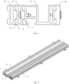
Fig. 1 is a cross-sectional view of a universal sill according to an embodiment of the present disclosure. -
Fig. 2 is an unassembled perspective view of a universal sill according to an embodiment of the present disclosure. -
Fig. 3 is an assembled perspective view of a universal sill according to an embodiment of the present disclosure. -
- C middle part
- A first part
- B second part
- 1 dovetail groove
- 2 mating convex part
- 3 mating concave part
- In order to make the purpose, technical details and advantages of the technical solution of the present disclosure more clear, the technical solution of the embodiment of the present disclosure will be described clearly and completely in the following with the accompanying drawings of specific embodiments of the present disclosure. Like reference numerals in the drawings represent like parts. It should be noted that the described embodiments are a part of the embodiments of the present disclosure, not the whole embodiments. Based on the described embodiments of the present disclosure, all other embodiments obtained by ordinary skilled in the art without creative labor belong to the scope of protection of the present disclosure.
- Unless otherwise defined, technical terms or scientific terms used herein shall have their ordinary meanings as understood by ordinary skilled in the art to which the present disclosure belongs. The words "first", "second" and similar words used in the specification and claims of the patent application of the present disclosure do not indicate any order, quantity or importance, but are only used to distinguish different components. Similar words such as "including" or "comprising" mean that the elements or objects appearing before the word cover the elements or objects listed after the word and their equivalents, without excluding other elements or objects. Similar words such as "connect" or "connected" are not limited to physical or mechanical connection, but can include electrical connection, whether direct or indirect. "Up", "Down", "Left" and "Right" are only used to indicate the relative positional relationship. When the absolute position of the described object changes, the relative positional relationship may also change accordingly.
- The present disclosure will be described in detail below by describing example embodiments.
- In the following description, a direction of door opening and closing is defined as a length direction, the direction perpendicular to the length direction in the horizontal plane is defined as the width direction, and the vertical direction perpendicular to the horizontal plane is defined as the height direction.
-
Fig. 1 is a cross-sectional view of a universal sill according to an embodiment of the present disclosure. The universal sill is configured to be installed at the floor of an elevator landing, thereby guiding a landing door provided at the landing. Referring toFig. 1 , the universal sill according to the present disclosure includes a middle part C and an additional part directly or indirectly assembled to the middle part. According to the additional part assembled to the middle part from the left side or the right side, the type of the additional part can be divided into the left part and the right part.Fig. 2 is a view of the parts before assembly, andFig. 3 is a view of the parts after assembly. Based on the middle part C, a side close to the middle part C is called the inner side, and a side away from the middle part C is called the outer side. - The middle part C includes a groove extending in the length direction, and the groove is formed as a guide rail for guiding a door to open and close. The middle part C further includes a fastener accommodating part, the fastener accommodating part includes an opening that opens downward and the width of the opening is smaller than the width of the fastener accommodating part, and the fastener accommodating part is configured to allow a screw to fasten the middle part C to the floor. Specifically, the screw head of the screw may be accommodated in the fastener accommodating part and the width of the screw head is greater than the width of the opening, and the shaft portion of the screw may be fastened to the floor through the opening, thereby fastening the middle part C to the floor.
Dovetail grooves 1 are arranged at the outer sides of the left and right ends of the middle part C for assembling the left part and the right part. - One or more additional parts can be provided, for example, any number of left parts, any number of right parts, any number of left parts and any number of right parts.
- If the left part is assembled, one or more left parts can be provided, and the left parts are configured to be assembled to the middle part C from the left side. If the right part is assembled, one or more right parts can be provided, and the right parts are configured to be assembled to the middle part C from the right side. The inner sides of the left part and the right part are provided with protrusions, and the protrusions are configured to match with the
dovetail groove 1 on the outer side of the middle part C or an adjacent inner part, so that the left part or the right part is assembled to the middle part C or the adjacent inner part. For example, the left part closest to the middle part C among the one or more left parts is assembled to the middle part C through the protrusion arranged on the inner side (here, the right side) and thedovetail groove 1 arranged on the left side of the middle part C, and the right part closest to the middle part C among the one or more right parts is assembled to the middle part C through the protrusion arranged on the inner side (here, the left side) and thedovetail groove 1 arranged on the right side of the middle part C, the outer part of the one or more left parts and one or more right side parts is assembled to the adjacent inner part through a protrusion arranged on the inner side of the outer part and thedovetail groove 1 arranged on the outer side of the adjacent inner part. The outer sides of the left parts and the right parts may or may not be provided withdovetail grooves 1, and the part without thedovetail groove 1 can only be assembled to the outermost side of the left side or the right side. - Additional parts (left parts and right parts) may be fastened to the middle part C by screws, as shown in
Fig. 1 . - The inner upper end and the inner lower end of the additional parts (the left part and the right part) are provided with mating
convex parts 2 protruding inward, which are configured to be in interference fit with matingconcave parts 3 arranged on the outer side of the adjacent inner part or the middle part C, so that it is not easy for the two parts that are mated to slide relatively, and a relatively flat sill surface can be obtained to increase passenger friendliness and aesthetics. - The additional parts (left parts and right parts) are symmetrical about a horizontal plane bisecting a height of the additional parts. Through the symmetrical design, the left part can act as the right part, and the right part can act as the left part, as long as it is turned by 180 degrees, so the design can reduce the specification number of parts.
- In order to adapt to different widths when replacing the sill, one or more left parts can be assembled on the left side of the middle part C, and/or one or more right parts can be assembled on the right side of the middle part C. Because the width of the universal sill is limited by the total width of the one or more left parts, the middle part C and one or more right parts which are assembled, different total widths can be obtained by changing the number of left parts and right parts, that is, the width of the universal sill varies according to one or more left parts and/or one or more right parts which are actually assembled.
- In order to more easily adapt to different widths and limit the number of parts to be processed when replacing the sill, in addition to making the left part and the right part symmetrical up and down, the left part and the right part can be defined with a certain number of specifications under the condition that the width of the middle part C is fixed. For example, the left part and the right part are selected from a first part A and a second part B. For example, the first part A has a plurality of selectable first widths, and the second part B has a fixed second width. For example, the plurality of selectable first widths are 10mm, 15mm and 20mm, and the second width is 5 mm. Then, by selecting any number of first parts A and/or second parts B on the left and right sides, a variety of different total widths can be achieved. In the embodiment of
Fig. 1 , two first parts A are selected on the left side and the second part B is selected on the right side, that is, the assembled sill is A+A+C+B. It should be noted that the number of selected parts on the left and right sides can be arbitrary, for example, the assembled sill can be A+C, C+B, A+C+A, B+A+C+B, B+A+C+A+A+B, etc. - Optionally, the outer side of the first part A is provided with a
dovetail groove 1, and the outer side of the second part B is not provided with adovetail groove 1. In this case, the second part B can only be provided on the outermost side on the left or right side. Moreover, in this case, because the second part B is arranged at the outermost side, the outer side of the second part B may not be provided with the matingconcave part 3. - In order to adapt to different heights when replacing the sill, the additional part and the middle part C can have selectable heights, for example, all of them have a height of 20mm, 25mm or 30 mm.
- The exemplary implementation of the universal sill proposed by the present disclosure has been described in detail above with reference to the preferred embodiment. However, those skilled in the art can understand that various variations and modifications can be made to the above specific embodiment without departing from the concept of the present disclosure, and various technical features and structures proposed by the present disclosure can be combined in various ways without exceeding the protection scope of the present disclosure.
Claims (11)
- A universal sill, comprising:a middle part (C), comprising a guide rail configured to guide a door to open and close in a length direction; andone or more additional parts (A; B), configured to be assembled to the middle part,wherein a total width of the middle part and the one or more additional parts after assembly defines a width of the universal sill, and the width of the universal sill varies according to the one or more additional parts actually assembled.
- The universal sill according to claim 1, wherein the one or more additional parts comprise one or more left parts and/or one or more right parts, the one or more left parts are configured to be assembled to the middle part (C) from a left side, and the one or more right parts are configured to be assembled to the middle part from a right side.
- The universal sill according to claim 1, wherein a part of the additional parts closest to the middle part (C) is assembled to the middle part through a dovetail groove (1) provided in the middle part.
- The universal sill according to claim 1, wherein an outer part of the additional parts is assembled to an adjacent inner part through a dovetail groove (1) arranged on an outer side of the adjacent inner part.
- The universal sill according to claim 1, wherein an inner upper end and an inner lower end of the additional parts are provided with mating convex parts (2) protruding inward, which are configured to be in interference fit with mating concave parts (3) arranged on an outer side of an adjacent inner part or the middle part (C).
- The universal sill according to any one of claims 1-5, wherein the additional parts are symmetrical about a horizontal plane bisecting a height of the additional parts.
- The universal sill according to any one of claims 1-5, wherein each of the additional parts is selected from a first part (A) and a second part (B), the first part has a plurality of selectable first widths, the second part has a fixed second width, and the middle part has a fixed middle width.
- The universal sill according to claim 7, wherein the plurality of selectable first widths are 10 mm, 15 mm and 20 mm, and the second width is 5 mm.
- The universal sill according to claim 7, wherein an outer side of the first part (A) is provided with a dovetail groove (1), and an outer side of the second part (B) is not provided with a dovetail groove.
- The universal sill according to any one of claims 1-5, wherein the additional parts (A; B) and the middle part (C) have selectable heights.
- An elevator, comprising the universal sill according to any one of claims 1-10, wherein the universal sill is configured to be installed at a floor of an elevator landing.
Applications Claiming Priority (1)
| Application Number | Priority Date | Filing Date | Title |
|---|---|---|---|
| CN202310392916.5A CN116639576A (en) | 2023-04-13 | 2023-04-13 | Universal Thresholds and Lifts |
Publications (1)
| Publication Number | Publication Date |
|---|---|
| EP4446270A1 true EP4446270A1 (en) | 2024-10-16 |
Family
ID=87638837
Family Applications (1)
| Application Number | Title | Priority Date | Filing Date |
|---|---|---|---|
| EP24169916.4A Pending EP4446270A1 (en) | 2023-04-13 | 2024-04-12 | Universal sill and an elevator |
Country Status (2)
| Country | Link |
|---|---|
| EP (1) | EP4446270A1 (en) |
| CN (1) | CN116639576A (en) |
Citations (4)
| Publication number | Priority date | Publication date | Assignee | Title |
|---|---|---|---|---|
| US1715188A (en) * | 1928-06-13 | 1929-05-28 | Bullock John | Elevator saddle |
| JP2004269218A (en) * | 2003-03-11 | 2004-09-30 | Toshiba Elevator Co Ltd | Elevator sill |
| JP2006347728A (en) * | 2005-06-17 | 2006-12-28 | Mitsubishi Electric Corp | Sill device of elevator |
| JP2010208767A (en) * | 2009-03-09 | 2010-09-24 | Toshiba Elevator Co Ltd | Sill structure for elevator |
Family Cites Families (11)
| Publication number | Priority date | Publication date | Assignee | Title |
|---|---|---|---|---|
| JP3042922U (en) * | 1997-03-17 | 1997-11-04 | 株式会社ブィテックス | Assembly structure of sill and kamoi materials |
| CA2214734A1 (en) * | 1997-09-08 | 1999-03-08 | Royal Group Technologies Limited | Composite door frames |
| JP2000072364A (en) * | 1998-08-27 | 2000-03-07 | Hitachi Building Systems Co Ltd | Elevator car threshold |
| JP2007186306A (en) * | 2006-01-13 | 2007-07-26 | Mitsubishi Electric Corp | Elevator sill equipment |
| DE202007015160U1 (en) * | 2007-10-30 | 2009-03-12 | Frey, Inge | Door frame with a threshold |
| JP5932081B1 (en) * | 2015-02-27 | 2016-06-08 | 東芝エレベータ株式会社 | Elevator running clearance occlusion device |
| CN207774523U (en) * | 2017-11-30 | 2018-08-28 | 青岛一建集团有限公司 | The novel and multifunctional protective device of elevator threshold |
| KR20200027733A (en) * | 2018-09-05 | 2020-03-13 | 현대엘리베이터주식회사 | Elevator door sill structure adjustable for length |
| JP7135680B2 (en) * | 2018-09-28 | 2022-09-13 | 三菱電機ビルソリューションズ株式会社 | How to replace an elevator threshold |
| CN219689076U (en) * | 2023-04-13 | 2023-09-15 | 通力电梯有限公司 | Universal threshold and elevator |
| CN221503063U (en) * | 2023-12-28 | 2024-08-09 | 君旺窗业(上海)有限公司 | Reinforced barrier-free bridge-cut-off threshold structure |
-
2023
- 2023-04-13 CN CN202310392916.5A patent/CN116639576A/en active Pending
-
2024
- 2024-04-12 EP EP24169916.4A patent/EP4446270A1/en active Pending
Patent Citations (4)
| Publication number | Priority date | Publication date | Assignee | Title |
|---|---|---|---|---|
| US1715188A (en) * | 1928-06-13 | 1929-05-28 | Bullock John | Elevator saddle |
| JP2004269218A (en) * | 2003-03-11 | 2004-09-30 | Toshiba Elevator Co Ltd | Elevator sill |
| JP2006347728A (en) * | 2005-06-17 | 2006-12-28 | Mitsubishi Electric Corp | Sill device of elevator |
| JP2010208767A (en) * | 2009-03-09 | 2010-09-24 | Toshiba Elevator Co Ltd | Sill structure for elevator |
Also Published As
| Publication number | Publication date |
|---|---|
| CN116639576A (en) | 2023-08-25 |
Similar Documents
| Publication | Publication Date | Title |
|---|---|---|
| US20190386443A1 (en) | Busway Systems and Related Assemblies and Methods | |
| US10072687B2 (en) | Board interlocking structure | |
| US11133629B2 (en) | Busway systems and related assemblies and methods | |
| EP4604156A1 (en) | Shell and relay | |
| CN210270727U (en) | Server | |
| CN219689076U (en) | Universal threshold and elevator | |
| KR101275503B1 (en) | Deck connector | |
| RU2421375C2 (en) | Aircraft wheel, aircraft wheel panel and aircraft | |
| US12193589B2 (en) | Mounting device for a curtain | |
| US11285889B2 (en) | Harness guide | |
| HU223720B1 (en) | Electrical equipment support for attachment to trunking | |
| KR20180010934A (en) | Connector assembly having protect plate | |
| JP2024513574A (en) | sealed battery housing | |
| CN116639576A (en) | Universal Thresholds and Lifts | |
| US20190086044A1 (en) | Recessed light fixture | |
| US20080229541A1 (en) | End Cap | |
| KR20190084546A (en) | Door apparatus | |
| CN111480267A (en) | Terminal block and air conditioner | |
| US10151319B2 (en) | Wiring box fixing structure for ventilating fan | |
| CN223470260U (en) | Air conditioner indoor unit and air conditioner | |
| CN205615323U (en) | A open roof structure that is used for driving guidance assembly of cable and is used for vehicle | |
| CN211448242U (en) | Magnetic suspension automatic door capable of self-adapting to width of door body | |
| EP1657206A2 (en) | Elevator car with simplified assembly | |
| US20110303797A1 (en) | Power pole extender | |
| CN224021115U (en) | A multifunctional separator seal |
Legal Events
| Date | Code | Title | Description |
|---|---|---|---|
| PUAI | Public reference made under article 153(3) epc to a published international application that has entered the european phase |
Free format text: ORIGINAL CODE: 0009012 |
|
| STAA | Information on the status of an ep patent application or granted ep patent |
Free format text: STATUS: THE APPLICATION HAS BEEN PUBLISHED |
|
| AK | Designated contracting states |
Kind code of ref document: A1 Designated state(s): AL AT BE BG CH CY CZ DE DK EE ES FI FR GB GR HR HU IE IS IT LI LT LU LV MC ME MK MT NL NO PL PT RO RS SE SI SK SM TR |
|
| RAP1 | Party data changed (applicant data changed or rights of an application transferred) |
Owner name: KONE CORPORATION |
|
| P01 | Opt-out of the competence of the unified patent court (upc) registered |
Free format text: CASE NUMBER: APP_876/2025 Effective date: 20250108 |
|
| STAA | Information on the status of an ep patent application or granted ep patent |
Free format text: STATUS: REQUEST FOR EXAMINATION WAS MADE |
|
| 17P | Request for examination filed |
Effective date: 20250319 |