EP4446263A1 - Package grouping apparatus for a packaging machine, packaging machine having a package grouping apparatus and a method of grouping packages - Google Patents
Package grouping apparatus for a packaging machine, packaging machine having a package grouping apparatus and a method of grouping packages Download PDFInfo
- Publication number
- EP4446263A1 EP4446263A1 EP24168355.6A EP24168355A EP4446263A1 EP 4446263 A1 EP4446263 A1 EP 4446263A1 EP 24168355 A EP24168355 A EP 24168355A EP 4446263 A1 EP4446263 A1 EP 4446263A1
- Authority
- EP
- European Patent Office
- Prior art keywords
- packages
- package
- grouping
- carts
- engagement element
- Prior art date
- Legal status (The legal status is an assumption and is not a legal conclusion. Google has not performed a legal analysis and makes no representation as to the accuracy of the status listed.)
- Granted
Links
Images




Classifications
-
- B—PERFORMING OPERATIONS; TRANSPORTING
- B65—CONVEYING; PACKING; STORING; HANDLING THIN OR FILAMENTARY MATERIAL
- B65G—TRANSPORT OR STORAGE DEVICES, e.g. CONVEYORS FOR LOADING OR TIPPING, SHOP CONVEYOR SYSTEMS OR PNEUMATIC TUBE CONVEYORS
- B65G54/00—Non-mechanical conveyors not otherwise provided for
- B65G54/02—Non-mechanical conveyors not otherwise provided for electrostatic, electric, or magnetic
-
- B—PERFORMING OPERATIONS; TRANSPORTING
- B65—CONVEYING; PACKING; STORING; HANDLING THIN OR FILAMENTARY MATERIAL
- B65G—TRANSPORT OR STORAGE DEVICES, e.g. CONVEYORS FOR LOADING OR TIPPING, SHOP CONVEYOR SYSTEMS OR PNEUMATIC TUBE CONVEYORS
- B65G47/00—Article or material-handling devices associated with conveyors; Methods employing such devices
- B65G47/02—Devices for feeding articles or materials to conveyors
- B65G47/04—Devices for feeding articles or materials to conveyors for feeding articles
- B65G47/06—Devices for feeding articles or materials to conveyors for feeding articles from a single group of articles arranged in orderly pattern, e.g. workpieces in magazines
- B65G47/08—Devices for feeding articles or materials to conveyors for feeding articles from a single group of articles arranged in orderly pattern, e.g. workpieces in magazines spacing or grouping the articles during feeding
- B65G47/082—Devices for feeding articles or materials to conveyors for feeding articles from a single group of articles arranged in orderly pattern, e.g. workpieces in magazines spacing or grouping the articles during feeding grouping articles in rows
-
- B—PERFORMING OPERATIONS; TRANSPORTING
- B65—CONVEYING; PACKING; STORING; HANDLING THIN OR FILAMENTARY MATERIAL
- B65G—TRANSPORT OR STORAGE DEVICES, e.g. CONVEYORS FOR LOADING OR TIPPING, SHOP CONVEYOR SYSTEMS OR PNEUMATIC TUBE CONVEYORS
- B65G47/00—Article or material-handling devices associated with conveyors; Methods employing such devices
- B65G47/02—Devices for feeding articles or materials to conveyors
- B65G47/04—Devices for feeding articles or materials to conveyors for feeding articles
- B65G47/06—Devices for feeding articles or materials to conveyors for feeding articles from a single group of articles arranged in orderly pattern, e.g. workpieces in magazines
- B65G47/08—Devices for feeding articles or materials to conveyors for feeding articles from a single group of articles arranged in orderly pattern, e.g. workpieces in magazines spacing or grouping the articles during feeding
- B65G47/084—Devices for feeding articles or materials to conveyors for feeding articles from a single group of articles arranged in orderly pattern, e.g. workpieces in magazines spacing or grouping the articles during feeding grouping articles in a predetermined 2-dimensional pattern
- B65G47/086—Devices for feeding articles or materials to conveyors for feeding articles from a single group of articles arranged in orderly pattern, e.g. workpieces in magazines spacing or grouping the articles during feeding grouping articles in a predetermined 2-dimensional pattern cubiform articles
-
- B—PERFORMING OPERATIONS; TRANSPORTING
- B65—CONVEYING; PACKING; STORING; HANDLING THIN OR FILAMENTARY MATERIAL
- B65G—TRANSPORT OR STORAGE DEVICES, e.g. CONVEYORS FOR LOADING OR TIPPING, SHOP CONVEYOR SYSTEMS OR PNEUMATIC TUBE CONVEYORS
- B65G47/00—Article or material-handling devices associated with conveyors; Methods employing such devices
- B65G47/52—Devices for transferring articles or materials between conveyors i.e. discharging or feeding devices
- B65G47/53—Devices for transferring articles or materials between conveyors i.e. discharging or feeding devices between conveyors which cross one another
-
- B—PERFORMING OPERATIONS; TRANSPORTING
- B65—CONVEYING; PACKING; STORING; HANDLING THIN OR FILAMENTARY MATERIAL
- B65G—TRANSPORT OR STORAGE DEVICES, e.g. CONVEYORS FOR LOADING OR TIPPING, SHOP CONVEYOR SYSTEMS OR PNEUMATIC TUBE CONVEYORS
- B65G47/00—Article or material-handling devices associated with conveyors; Methods employing such devices
- B65G47/52—Devices for transferring articles or materials between conveyors i.e. discharging or feeding devices
- B65G47/68—Devices for transferring articles or materials between conveyors i.e. discharging or feeding devices adapted to receive articles arriving in one layer from one conveyor lane and to transfer them in individual layers to more than one conveyor lane or to one broader conveyor lane, or vice versa, e.g. combining the flows of articles conveyed by more than one conveyor
- B65G47/71—Devices for transferring articles or materials between conveyors i.e. discharging or feeding devices adapted to receive articles arriving in one layer from one conveyor lane and to transfer them in individual layers to more than one conveyor lane or to one broader conveyor lane, or vice versa, e.g. combining the flows of articles conveyed by more than one conveyor the articles being discharged or distributed to several distinct separate conveyors or to a broader conveyor lane
- B65G47/715—Devices for transferring articles or materials between conveyors i.e. discharging or feeding devices adapted to receive articles arriving in one layer from one conveyor lane and to transfer them in individual layers to more than one conveyor lane or to one broader conveyor lane, or vice versa, e.g. combining the flows of articles conveyed by more than one conveyor the articles being discharged or distributed to several distinct separate conveyors or to a broader conveyor lane to a broader conveyor lane
-
- B—PERFORMING OPERATIONS; TRANSPORTING
- B65—CONVEYING; PACKING; STORING; HANDLING THIN OR FILAMENTARY MATERIAL
- B65G—TRANSPORT OR STORAGE DEVICES, e.g. CONVEYORS FOR LOADING OR TIPPING, SHOP CONVEYOR SYSTEMS OR PNEUMATIC TUBE CONVEYORS
- B65G47/00—Article or material-handling devices associated with conveyors; Methods employing such devices
- B65G47/74—Feeding, transfer, or discharging devices of particular kinds or types
- B65G47/82—Rotary or reciprocating members for direct action on articles or materials, e.g. pushers, rakes, shovels
Definitions
- the present invention relates to a package grouping apparatus for the grouping of packages, in particular of packages filled with a pourable product, even more particular of packages formed from a multilayer packaging material and filled with a pourable product.
- the present invention also relates to a packaging machine having a package grouping apparatus.
- the present invention also relates to a method of grouping packages, in particular of packages filled with a pourable product, even more particular of packages formed from a multilayer packaging material and filled with a pourable product.
- liquid or pourable food products such as fruit juice, UHT (ultra-high-temperature treated) milk, wine, tomato sauce, etc.
- UHT ultra-high-temperature treated milk
- wine wine
- tomato sauce etc.
- a typical example is the parallelepiped-shaped package for pourable food products known as Tetra Brik Aseptic (registered trademark), which is made by sealing and folding a laminated strip packaging material.
- the packaging material has a multilayer structure comprising a carton and/or paper base layer, covered on both sides with layers of heat-seal plastic material, e.g. polyethylene.
- the packaging material also comprises a layer of oxygen-barrier material, e.g. an aluminum foil, which is superimposed on a layer of heat-seal plastic material, and is in turn covered with another layer of heat-seal plastic material forming the inner face of the package eventually contacting the food product.
- Composite packages of this sort are normally produced within fully automatic packaging machines, which at least form the composite packages from the multilayer packaging material and fill the composite packages with the pourable food product.
- a typical packaging machine comprises at least a package forming apparatus, which forms the composite packages from the multilayer packaging material and which also fills the composite packages with the pourable food product.
- packaging machines also comprise downstream equipment, which receives the composite packages from the package forming apparatus.
- the downstream equipment may comprise a package grouping apparatus configured to form respective groups of packages from a succession of advancing packages.
- Known package grouping apparatuses may comprise mechanical means so as to divide the succession of packages into a plurality of parallel streams of packages and to compact some of the packages of the plurality of streams for obtaining respective groups.
- Number 1 indicates as a whole a package grouping apparatus for forming groups 2 of packages 3.
- packages 3 are filled with a pourable product, more preferentially a pourable food product, such as milk, cream, fruit juice, wine, tomato sauce, sugar, salt, emulsions, solutions containing solid particles (e.g. legumes) .
- a pourable food product such as milk, cream, fruit juice, wine, tomato sauce, sugar, salt, emulsions, solutions containing solid particles (e.g. legumes) .
- packages 3 may be formed from a multilayer packaging material.
- the multilayer packaging material may comprise at least a layer of fibrous material, such as e.g. a paper or cardboard layer, and at least two layers of heat-seal plastic material, e.g. polyethylene, interposing the layer of fibrous material in between one another.
- a layer of fibrous material such as e.g. a paper or cardboard layer
- heat-seal plastic material e.g. polyethylene
- the multilayer packaging material may also comprise a layer of gas- and light-barrier material, e.g. aluminum foil or ethylene vinyl alcohol (EVOH) film, in particular being arranged between one of the layers of the heat-seal plastic material and the layer of fibrous material.
- the multilayer packaging material may also comprise a further layer of heat-seal plastic material being interposed between the layer of gas- and light-barrier material and the layer of fibrous material.
- package grouping apparatus 1 may be part of a packaging machine, the packaging machine being configured to form packages 3 filled with a pourable product, preferentially packages 3 formed from the multilayer packaging material.
- the packaging machine may comprise a package forming apparatus configured to form and/or fill packages 3.
- the packaging machine may comprise a conveyor configured to convey packages 3 from the package forming apparatus to package grouping apparatus 1.
- the package forming apparatus may be arranged upstream of package grouping apparatus 1; i.e. package grouping apparatus 1 may receive, in use, packages 3 from the package forming apparatus.
- the multilayer packaging material may be provided in the form of a web, in particular being wound up on a bobbin.
- the package forming apparatus may be configured to sterilize, to form, seal, fill and cut the web so as to obtain packages 3 being filled with the pourable product.
- the package forming apparatus may be configured to form a tube from the web of the multilayer packaging material, to longitudinally seal the tube, to fill the tube with the pourable product and to transversally seal and cut the tube.
- the web may comprise a succession of connected blanks.
- the blanks may be defined by a succession of repeated patterns provided on the web, more preferentially each pattern defining at least partially the aesthetical appearance of the finalized package 2.
- the multilayer packaging material may be provided in the form of single package blank, which, in use, are singularly formed and filled.
- each package 3 may extend along a longitudinal axis and may comprise at least two transversal walls (being transversal to the respective longitudinal axis) and being disposed at opposite sides of package 3 and a side wall extending between the transversal walls.
- one respective transversal wall of each package 3 may define a bottom wall and the other respective transversal wall may define a top wall.
- the bottom wall may define a support surface adapted to be placed on a (horizontal) plane or any other kind of support.
- package grouping apparatus 1 may comprise:
- grouping system 5 may be configured to form one or more groups 2 of packages 3 during advancement of packages 3 along advancement path P, preferentially along a grouping portion P1 of advancement path P.
- grouping portion P1 may have a rectilinear shape.
- each group 2 may comprise at least one leading package 3 and one trailing package 3.
- each trailing package 3 is the respective package 3 of the respective group 2 being arranged upstream with respect to the other packages 3 of the respective group 2 and with regard to advancement path P and each leading package 3 is arranged downstream with respect to the other packages 3 of the respective group 2 and with regard to advancement path P.
- each leading package 3 is the first package 3 of the respective group 2 and each trailing package 3 is the last package 3 of the respective group 2 and with respect to advancement path P.
- the packages 3 of each group 2 are arranged in a row; i.e. one after the other.
- grouping system 5 may be configured to compact the respective packages 3 of each group 2; i.e. each package 3 of each group 2 abuts against at least one neighboring package 3 of the respective group 2.
- the respective leading package 3 and the respective trailing package 3 of each group 2 are in contact with only one neighboring package 3, while these packages 3 of each group 2 which are interposed between the respective leading package 3 and the respective trailing package 3 are in contact with two respective neighboring packages 3 (in particular, one neighboring package 3 being arranged upstream and the other neighboring package 3 being arranged downstream).
- packages 3 advancing, in use, along advancement path P are arranged one after the other, e.g. packages 3 may be spaced apart from one another (i.e. not being in contact with one another). Operation of grouping system 5 allows to define groups 2 of packages 3 and to compact the respective packages 3 (i.e. after compaction, the respective packages 3 are approached to one another and each one is in contact with at least one other package 3 of the respective group 2).
- grouping system 5 may comprise:
- Each cart 7 may comprise a respective engagement element 9, each engagement element 9 being configured to be controlled into abutment with at least one package 3.
- the actuation unit may be configured to control advancement of independent carts 7 such to form, preferentially to at least temporaneously form, for each group 2 of packages 3 a respective pair of independent carts 7, preferentially the respective pair of carts 7 being controlled such to define the packages 3 being part of the respective group 2, and more preferentially to also compact the respective packages 3.
- the actuation unit may be configured to control the respective carts 7 of each pair such that the respective engagement element 9 of one of the independent carts 7 engages with the respective leading package 3 and the respective engagement element 9 of the other one of the respective independent carts 7 engages the respective trailing package 3.
- each pair of carts 7 comprises a leading cart 7 and a trailing cart 7 with regard to endless path S; i.e. the respective leading cart 7 is arranged upstream from the respective trailing cart 7.
- the actuation unit may be configured such to control advancement of the respective leading cart 7 and of the respective trailing cart 7 such that the engagement element 9 of the respective leading cart 7 and of the respective trailing cart 7 engage, respectively, the leading package 3 and the trailing package 3.
- the actuation unit is configured to control advancement of the respective carts 7 of each pair of carts 7 such that the respective packages 3 of each group 2 are interposed between the respective engagement elements 9.
- the actuation unit may also be configured to control advancement of the respective carts 7 of each pair of carts 7 such to compact the respective packages 3 of the respective group 2 (i.e. the respective packages 3 are brought into contact with one another; in other words, each package 3 of each group 2 is after compaction in contact with at least one other package 3 of the respective group 2).
- each independent cart 7 comprises a powering unit configured to control movement of the respective engagement element 9 from a respective rest position to a respective active position, and preferentially from the respective active position to the respective rest position.
- each engagement element 9 may be in a retracted position and an extracted position when being controlled into, respectively, the respective rest position and the respective active position.
- Each engagement element 9 moves away from the endless carrier 6 when being controlled from the rest (retracted) position to the active (extracted) position.
- Each engagement element 9 moves towards the endless carrier 6 when being controlled from the rest (retracted) position to the active (extracted) position.
- each engagement element 9 may be at least rectilinearly moveable between the respective rest position and the respective active position.
- each engagement element 9 may be configured such to allow for the grouping and compaction of the respective group 2 when being in the respective rest position and to move, in particular in collaboration with the respective engagement element 9 of the other cart 7 of the respective pair of carts 7, the respective group 2, preferentially so as to discharge the respective group 2 from inlet conveying device 4.
- each powering unit may be configured to control movement of the respective engagement element 9 from the respective rest position to the respective active position after formation of the respective group 2 of packages 3 and for discharging the respective group 2 away from inlet conveying device 4.
- grouping system 5 may be configured to simultaneously control the respective engagement elements 9 of the respective carts 7 of each pair from the respective rest positions to the respective active positions.
- grouping system 5 may also comprise at least one energy transfer device 10 configured to transfer energy to the powering units of carts 7 during advancement of carts 7 along an energy transfer portion S1 of endless path S.
- Energy transfer device 10 may be configured such to provide to the powering units the energy needed to control the movement of the respective engagement elements 9 from the respective rest positions to the respective active positions, and preferentially from the respective active positions to the respective rest positions.
- energy transfer device 10 may be arranged such that the powering units receive the energy from energy transfer device 10 while the respective engagement elements 9 are controlled to move from the respective rest position to the respective active position, and preferentially also while controlling movement of the respective engagement elements 9 back from the respective active position to the respective rest configuration.
- each powering unit may be configured to move the respective engagement element 9 from the rest position to the active position during advancement of the respective independent cart 7 along energy transfer portion S1. In this way, one avoids the need to provide for significant energy storages provided on carts 7.
- energy transfer portion S1 may have a rectilinear shape.
- Such a solution is favorable as it is possible to transfer the energy to the powering units while moving the respective engagement elements 9 to the respective active positions and while group 2 of packages 3 advances along a rectilinear portion of advancement path P. This allows an easier handling of groups 2 in comparison to the case of removing groups 2 from inlet conveying device 4 during movement of groups 2 along curved portions.
- grouping system 5 may also comprise at least one communication device configured to communicate with carts 7, preferentially so as to exchange data, more preferentially in a bidirectional manner, between the communication device and a respective communication group of each cart 7.
- each energy transfer device 10 may comprise one respective communication device.
- each powering unit may comprise the respective communication group.
- each communication device may be configured to communicate with carts 7, preferentially the respective powering units, such to control the energy transfer to powering units.
- Figure 2a illustrates a succession of packages 3, in the specific case shown three, being advanced by inlet conveying device 4 along advancement path P.
- the packages 3 are spaced from one another (i.e. they are not in contact with one another), e.g. the packages 3 may be unequally spaced apart from one another or, in an alternative case not shown, may be equally spaced apart from one another.
- One of the respective carriers 7, in particular the leading carrier 7, of the respective pair advances such that the respective engagement element 9 is arranged upstream from the respective leading package 3, preferentially the respective engagement element 9 is put into contact with the respective leading package 3.
- the other one of the respective carriers 7, in particular the trailing carrier 7, of the respective pair advances such that the respective engagement element 9 is arranged downstream from the respective trailing package 3.
- the trailing carrier 7 advances such that the group 2 has the desired number of packages 3, in the specific case shown three, and is put into contact with the trailing package 3, preferentially thereby interposing the respective packages 3 of the respective group 2 in between the respective engagement elements 9.
- advancement of the respective leading carrier 7 and of the respective trailing carrier 7 may be coordinated such to obtain the desired group 2.
- the energy needed to control movement of engagement elements 9 from the respective rest positions to the respective active positions, and preferentially back to the respective rest positions, is provided to the powering units through energy transfer from energy transfer device 10 to the powering units. Preferentially, the energy transfer occurs while the respective engagement elements 9 are moved from the respective rest positions to the respective active positions.
- energy transfer device 10 may comprise one or more emitting coils and each powering unit may comprise at least one receiving coil. Moreover, the one or more emitting coils and each receiving coil may be configured such to transfer energy by means of induction energy transfer.
- the emitting coils are configured to generate an electromagnetic field and each receiving coil is configured to interact with the electromagnetic field so as to generate a current within the receiving coil.
- the thereby generated current can be used by the respective powering unit for moving the respective engagement element 9 from the rest position to the active position.
- powering units may be configured to directly control movement of the respective engagement elements 9 between the respective rest positions to the active positions.
- each powering unit may comprise at least one actuator connected to the respective engagement element 9 and the powering unit may be configured to control operation of the actuator such that the actuator moves the respective engagement element 9.
- grouping system 5 may comprise one or more mechanical cams.
- each mechanical cam may be configured such to allow for movement of engagement elements 9 at least from the respective rest positions to the respective active positions.
- each mechanical cam may be arranged adjacent to a section of advancement path P, at which groups 2 may be discharged from inlet conveying device 4.
- each powering unit may comprise at least one respective cam follower and at least one coupling group connected to the respective cam follower and coupling the respective cam follower to the respective engagement element 9.
- each powering unit may be configured to control the respective cam follower between a respective idle position and a respective operative position.
- each cam follower being controlled in the respective operative portion is adapted to interact with at least one mechanical cam at a time.
- each powering unit may be configured such to selectively control the respective cam follower in the respective operative position such that cam follower interacts with one respective mechanical cam at a time and the interaction is such that the respective engagement element 9 moves from the respective rest position to the respective active position.
- the energy of the powering unit may be set to be sufficient to move the cam follower and the energy for moving the respective group 2 originates from the interaction of the respective cam follower with the mechanical cam.
- each engagement element 9 from the respective active position to the respective rest position may be guided by interaction between the respective cam follower and the mechanical cam.
- each powering unit may be configured to control each cam follower back to the respective idle position, in the case that the respective engagement element 9 shall move back to the respective rest position.
- package grouping apparatus 1 may further comprise at least one outlet conveying system 15 configured to receive at least one respective group 2 of packages 3 discharged from inlet conveying device 4.
- outlet conveying system 15 may be configured to receive the respective group 2 during movement of the respective engagement elements 9 from the respective rest position to the respective active position.
- outlet conveying system 15 may be configured to receive a plurality of groups 2 of packages 3 so as to allow for the generation of a batch 16 of groups 2 of packages 3.
- each batch 16 may have an array arrangement of packages 3; i.e. packages 3 may be arranged in two dimensions; in other words, packages 3 may be aligned with respect to one another along a first direction D1 and a second direction D2 perpendicular to first direction D1.
- each batch 16 may result from feeding a plurality of groups 2 of packages 3 onto outlet conveying system 15, and more preferentially such that each group 2 is put into contact with at least one other group 2 of packages 3.
- outlet conveying system 15 may be configured to further advance groups 2 and/or batches 16.
- outlet conveying system 15 may be configured to advance groups 2 and/or batches 16 to one or more final packaging apparatuses (of the packaging machine and being) configured to further pack groups 2 and/or batches 16.
- Final packaging apparatuses may be chosen from the group of cardboard packers configured to pack each group 2 and/or batch 16 of packages 3 in a carton box and a wrapping machine configured to wrap each group 2 and/or batch 16 of packages 2 within a wrapping material, such as a web of plastic material.
- outlet conveying system 15 may be configured to receive one group 2 after the other group 2 of a plurality of respective groups 2 so as to form the respective batch 16. Preferentially, outlet conveying system 15 may be configured to further advance the respective batch 16 as a whole and not only the single received groups 2.
- outlet conveying system 15 may be arranged adjacent to inlet conveying device 4.
- At least one respective mechanical cam may be associated to outlet conveying system 15.
- each powering unit may be configured to control the respective cam follower into the respective operative position so as to allow transfer of the respective group 2 onto outlet conveying system 15.
- endless carrier 6 may have an annular shape.
- endless carrier 6 may comprises at least one rectilinear track 17. More preferentially, energy transfer device 10 may be arranged such that energy transfer portion S1 may be parallel to a portion of rectilinear track 17.
- endless carrier 6 may comprise a plurality of rectilinear tracks 17 and a plurality of curved tracks 18.
- endless track 15 has an oval shape.
- endless carrier 6 may comprise two rectilinear tracks 17 spaced apart from, and preferentially parallel to one another, and two opposed curved tracks 18 connected to rectilinear tracks 17.
- each engagement element 9 may be configured to at least laterally contact the respective packages 3. Preferentially, at least each engagement element 9 may be configured to contact the respective side walls of the respective packages 3.
- each engagement element 9 may comprise at least a first engagement surface 19 configured to contact the respective packages 3.
- each first engagement surface 19 may be arranged such to permit the compaction of the respective packages 3 of the respective group 2.
- each group 2 may be interposed between the two respective first engagement surfaces 19.
- each engagement element 9 may also comprise a second engagement surface 20 configured to contact the respective packages 3, and in particular being configured to facilitate the discharging of the respective groups 2 from inlet conveying device 4.
- first engagement surface 19 and the second engagement surface 20 may be perpendicular to one another.
- the actuation unit may be configured to selectively generate an electromagnetic field for selectively interacting with the plurality of carts 7 and for selectively advancing the plurality of carts 7 along endless path S.
- the actuation unit may comprise an annular housing and a plurality of coils arranged along and within the annular housing.
- the actuation unit may comprise a powering group operatively coupled to the plurality of coils and configured to selectively power each one of the plurality of coils.
- the selective advancement of carts 7 means that the actuation unit may accelerate and decelerate each cart 7 independently from one another. Certainly, the actuation unit operates such to avoid any collisions between carts 7 and such to coordinate movement of the respective carts 7 of each pair of carts 7 with respect to one another.
- each cart 7 may comprise a magnetic and/or paramagnetic element configured to interact with the electromagnetic field generated by the actuation unit.
- inlet conveying device 4 may comprise at least a rectilinear section 21.
- each powering unit may be configured to control the respective engagement element 9 from the respective rest position to the respective active position during advancement of the respective group 2 of packages 3 along at least a portion of rectilinear section 21.
- rectilinear section 21 may be parallel to energy transfer portion S1.
- inlet conveying device 4 may comprise a belt conveyor 22 configured to carry packages 3 and to advance packages 3 along advancement path P.
- package grouping apparatus 1 forms groups 2 of packages 3. Preferentially, the package grouping apparatus 1 receives the packages 3 from the package forming apparatus.
- the package forming apparatus forms and fills packages 3, preferentially from the multilayer packaging material.
- operation of package distributing apparatus 1 and the respective method of distributing the succession of packages 3 comprises the steps of:
- the step of grouping comprises the sub-steps of:
- the sub-step of controlling may be executed during the step of transferring energy.
- the respective groups 2 of packages 3 are fed to an outlet conveying system 15.
- operation of package grouping apparatus 1 also foresees that engagement elements 9 may be moved back to the respective rest position after discharging the respective group 2 and/or after transferring the respective group 2 to outlet conveying system 15.
- each powering unit may move the respective cam follower into the respective operative position and such that the respective cam follower interact with at least one respective mechanical cam leading to movement of the respective engagement element 9 into the respective active position.
- number 1' indicates an alternative package grouping apparatus according to the present invention; as package grouping apparatus 1' is similar to package grouping apparatus 1, the following description is limited to the differences between them, and using the same references, where possible, for identical or corresponding parts.
- package grouping apparatus 1' differs from package grouping apparatus 1 in comprising a plurality of outlet conveying systems 15, preferentially each one adjacently arranged to inlet conveying device 4.
- package grouping apparatus 1' may be configured such to transfer each group 2 to one respective outlet conveying system 15.
- outlet conveying systems 15 may be spaced apart from one another along advancement path P, preferentially along grouping portion P1.
- each powering unit may be configured to selectively control the respective cam follower into the respective operative position such that the respective group 2 is transferred onto the desired outlet conveying system 15.
- each powering unit does not control the respective cam follower into the operative position, but only controls the respective cam follower into the respective operative position such that the respective group 2 is transferred onto the desired outlet conveying system 15.
- package grouping apparatus 1' As operation of package grouping apparatus 1' is similar to operation of packaging grouping apparatus 1, we refer to the differences between operation of package grouping apparatus 1' and package grouping apparatus 1.
- number 1" indicates an alternative package grouping apparatus according to the present invention; as package grouping apparatus 1" is similar to package grouping apparatus 1, the following description is limited to the differences between them, and using the same references, where possible, for identical or corresponding parts.
- package grouping apparatus 1'' differs from package grouping apparatus 1 in comprising more than one energy transfer device 10 arranged at different positions.
- each energy transfer device 10 may be associated to one respective rectilinear track 17.
- package grouping apparatus 1'' comprises two energy transfer devices 10, one associated to a first rectilinear track 17 and the other one associated to a second rectilinear track 17 different from the first rectilinear track 17.
- the first rectilinear track 17 and the second rectilinear track 17 may be connected to one another by a respective curved track 18.
- package grouping apparatus 1" differs from package grouping apparatus 1 also in comprising more than one outlet conveying systems 15 arranged such that at least one respective outlet conveying system 15 may be associated to each energy transfer device 10.
- groups 2 can be transferred to the one or other outlet conveying system 15 in function of whether the one or other energy transfer device 10 transfers, in use, energy to the respective powering units.
- package grouping apparatus 1 As operation of package grouping apparatus 1" is similar to operation of packaging grouping apparatus 1, we refer to the differences between operation of package grouping apparatus 1" and package grouping apparatus 1.
- powering units receive energy from one or the other energy transfer device 10 so as to transfer the respective groups 2 to the desired outlet conveying system 15 by selectively moving the respective engagement elements 9 from the respective rest position to the respective active position.
- package grouping apparatuses 1, 1' and 1'' can be easily adapted to format changes.
- package grouping apparatus 1, 1' and 1'' can be easily modified e.g. by adding and/or activating and/or deactivating outlet conveying systems 15 so as to adapted to the specific temporary or permanent requirements.
- a further advantage of package grouping apparatus 1, 1' and 1'' resides in a reduction of the mechanical components.
Landscapes
- Engineering & Computer Science (AREA)
- Mechanical Engineering (AREA)
- Attitude Control For Articles On Conveyors (AREA)
Abstract
Description
- The present invention relates to a package grouping apparatus for the grouping of packages, in particular of packages filled with a pourable product, even more particular of packages formed from a multilayer packaging material and filled with a pourable product.
- Advantageously, the present invention also relates to a packaging machine having a package grouping apparatus.
- Advantageously, the present invention also relates to a method of grouping packages, in particular of packages filled with a pourable product, even more particular of packages formed from a multilayer packaging material and filled with a pourable product.
- As is known, many liquid or pourable food products, such as fruit juice, UHT (ultra-high-temperature treated) milk, wine, tomato sauce, etc., are sold in composite packages made of a multilayer packaging material.
- A typical example is the parallelepiped-shaped package for pourable food products known as Tetra Brik Aseptic (registered trademark), which is made by sealing and folding a laminated strip packaging material. The packaging material has a multilayer structure comprising a carton and/or paper base layer, covered on both sides with layers of heat-seal plastic material, e.g. polyethylene. In the case of aseptic packages for long-storage products, the packaging material also comprises a layer of oxygen-barrier material, e.g. an aluminum foil, which is superimposed on a layer of heat-seal plastic material, and is in turn covered with another layer of heat-seal plastic material forming the inner face of the package eventually contacting the food product.
- Composite packages of this sort are normally produced within fully automatic packaging machines, which at least form the composite packages from the multilayer packaging material and fill the composite packages with the pourable food product.
- A typical packaging machine comprises at least a package forming apparatus, which forms the composite packages from the multilayer packaging material and which also fills the composite packages with the pourable food product.
- Additionally, such packaging machines also comprise downstream equipment, which receives the composite packages from the package forming apparatus.
- The downstream equipment may comprise a package grouping apparatus configured to form respective groups of packages from a succession of advancing packages.
- Known package grouping apparatuses may comprise mechanical means so as to divide the succession of packages into a plurality of parallel streams of packages and to compact some of the packages of the plurality of streams for obtaining respective groups.
- Even though the known package grouping apparatuses work satisfyingly well, a need is felt in the sector to further improve the known Package grouping apparatuses and the respective method of distributing packages.
- It is therefore an object of the present invention to provide in an improved package grouping apparatus for forming groups of packages.
- It is a further object of the present invention to provide an improved packaging machine having a grouping apparatus.
- It is another object of the present invention to provide an improved method of forming groups of packages.
- According to the present invention, there is provided a package grouping apparatus according to the
independent claim 1. - Preferred embodiments of the package grouping apparatus are claimed in the claims being directly or indirectly dependent on
claim 1. - According to the present invention, there is also provided a packaging machine according to claim 12.
- According to the present invention, there is also provided a method according to the independent claim 13.
- Preferred embodiments of the method are claimed in the claims being directly or indirectly dependent on claim 13.
- Three non-limiting embodiments of the present invention will be described by way of example with reference to the accompanying drawings, in which:
-
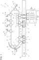
Figure 1 is a schematic top view of a package grouping apparatus according to a first embodiment of the present invention, with parts removed for clarity; -
Figures 2a to 2d is a schematic top view of the package grouping apparatus ofFigure 1 during different moments of operation, with parts removed for clarity; -
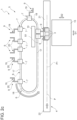
Figure 3 is a schematic top view of a package grouping apparatus according to a second embodiment of the present invention, with parts removed for clarity; and -
Figure 4 is a schematic top view of a package grouping apparatus according to a third embodiment of the present invention, with parts removed for clarity. -
Number 1 indicates as a whole a package grouping apparatus for forminggroups 2 ofpackages 3. - Preferentially,
packages 3 are filled with a pourable product, more preferentially a pourable food product, such as milk, cream, fruit juice, wine, tomato sauce, sugar, salt, emulsions, solutions containing solid particles (e.g. legumes) . - Preferentially,
packages 3 may be formed from a multilayer packaging material. - In more detail, the multilayer packaging material may comprise at least a layer of fibrous material, such as e.g. a paper or cardboard layer, and at least two layers of heat-seal plastic material, e.g. polyethylene, interposing the layer of fibrous material in between one another. One of these two layers of heat-seal plastic material defines an inner face of the
composite packages 3 eventually contacting the pourable food product packaged withinpackages 3. - According to some possible non-limiting embodiments, the multilayer packaging material may also comprise a layer of gas- and light-barrier material, e.g. aluminum foil or ethylene vinyl alcohol (EVOH) film, in particular being arranged between one of the layers of the heat-seal plastic material and the layer of fibrous material. In particular, the multilayer packaging material may also comprise a further layer of heat-seal plastic material being interposed between the layer of gas- and light-barrier material and the layer of fibrous material.
- According to some preferred non-limiting embodiments,
package grouping apparatus 1 may be part of a packaging machine, the packaging machine being configured to formpackages 3 filled with a pourable product, preferentiallypackages 3 formed from the multilayer packaging material. - Preferentially, the packaging machine may comprise a package forming apparatus configured to form and/or fill
packages 3. Moreover, the packaging machine may comprise a conveyor configured to conveypackages 3 from the package forming apparatus to packagegrouping apparatus 1. - The package forming apparatus may be arranged upstream of
package grouping apparatus 1; i.e.package grouping apparatus 1 may receive, in use,packages 3 from the package forming apparatus. - According to some preferred non-limiting embodiments, the multilayer packaging material may be provided in the form of a web, in particular being wound up on a bobbin. Accordingly, the package forming apparatus may be configured to sterilize, to form, seal, fill and cut the web so as to obtain
packages 3 being filled with the pourable product. In further detail, the package forming apparatus may be configured to form a tube from the web of the multilayer packaging material, to longitudinally seal the tube, to fill the tube with the pourable product and to transversally seal and cut the tube. - In more detail, the web may comprise a succession of connected blanks. Preferentially, the blanks may be defined by a succession of repeated patterns provided on the web, more preferentially each pattern defining at least partially the aesthetical appearance of the finalized
package 2. - Alternatively, the multilayer packaging material may be provided in the form of single package blank, which, in use, are singularly formed and filled.
- In more detail, each
package 3 may extend along a longitudinal axis and may comprise at least two transversal walls (being transversal to the respective longitudinal axis) and being disposed at opposite sides ofpackage 3 and a side wall extending between the transversal walls. - More specifically, one respective transversal wall of each
package 3 may define a bottom wall and the other respective transversal wall may define a top wall. In particular, the bottom wall may define a support surface adapted to be placed on a (horizontal) plane or any other kind of support. - With particular reference to
Figures 1 ,package grouping apparatus 1 may comprise: - an
inlet conveying device 4 configured to advance the succession ofpackages 3 along an advancement path P; and - a
grouping system 5 configured to form one ormore groups 2 ofpackages 3. - In more detail,
grouping system 5 may be configured to form one ormore groups 2 ofpackages 3 during advancement ofpackages 3 along advancement path P, preferentially along a grouping portion P1 of advancement path P. Preferentially, grouping portion P1 may have a rectilinear shape. - Advantageously, each
group 2 may comprise at least one leadingpackage 3 and onetrailing package 3. - In more detail, each
trailing package 3 is therespective package 3 of therespective group 2 being arranged upstream with respect to theother packages 3 of therespective group 2 and with regard to advancement path P and each leadingpackage 3 is arranged downstream with respect to theother packages 3 of therespective group 2 and with regard to advancement path P. In alternative words, each leadingpackage 3 is thefirst package 3 of therespective group 2 and eachtrailing package 3 is thelast package 3 of therespective group 2 and with respect to advancement path P. - Advantageously, the
packages 3 of eachgroup 2 are arranged in a row; i.e. one after the other. - Preferentially,
grouping system 5 may be configured to compact therespective packages 3 of eachgroup 2; i.e. eachpackage 3 of eachgroup 2 abuts against at least one neighboringpackage 3 of therespective group 2. In more detail, the respective leadingpackage 3 and the respectivetrailing package 3 of eachgroup 2 are in contact with only one neighboringpackage 3, while thesepackages 3 of eachgroup 2 which are interposed between the respective leadingpackage 3 and the respectivetrailing package 3 are in contact with two respective neighboring packages 3 (in particular, one neighboringpackage 3 being arranged upstream and the other neighboringpackage 3 being arranged downstream). - Advantageously and as will be explained in more detail further below, prior to operation of
grouping system 5,packages 3 advancing, in use, along advancement path P are arranged one after the other,e.g. packages 3 may be spaced apart from one another (i.e. not being in contact with one another). Operation ofgrouping system 5 allows to definegroups 2 ofpackages 3 and to compact the respective packages 3 (i.e. after compaction, therespective packages 3 are approached to one another and each one is in contact with at least oneother package 3 of the respective group 2). - With particular reference to
Figures 1 to 2d ,grouping system 5 may comprise: - an
endless carrier 6; - a plurality of
independent carts 7 moveably coupled toendless carrier 6; and - an actuation unit configured to selectively advance
carts 7 alongendless carrier 6 and along an endless path S, preferentially defined by (the shape of)endless carrier 6. - Each
cart 7 may comprise arespective engagement element 9, eachengagement element 9 being configured to be controlled into abutment with at least onepackage 3. - In more detail, the actuation unit may be configured to control advancement of
independent carts 7 such to form, preferentially to at least temporaneously form, for eachgroup 2 of packages 3 a respective pair ofindependent carts 7, preferentially the respective pair ofcarts 7 being controlled such to define thepackages 3 being part of therespective group 2, and more preferentially to also compact therespective packages 3. - In further detail, the actuation unit may be configured to control the
respective carts 7 of each pair such that therespective engagement element 9 of one of theindependent carts 7 engages with the respective leadingpackage 3 and therespective engagement element 9 of the other one of the respectiveindependent carts 7 engages the respective trailingpackage 3. - More specifically, each pair of
carts 7 comprises a leadingcart 7 and a trailingcart 7 with regard to endless path S; i.e. the respectiveleading cart 7 is arranged upstream from the respective trailingcart 7. - Moreover, the actuation unit may be configured such to control advancement of the respective
leading cart 7 and of the respective trailingcart 7 such that theengagement element 9 of the respectiveleading cart 7 and of the respective trailingcart 7 engage, respectively, the leadingpackage 3 and the trailingpackage 3. - Advantageously, the actuation unit is configured to control advancement of the
respective carts 7 of each pair ofcarts 7 such that therespective packages 3 of eachgroup 2 are interposed between therespective engagement elements 9. - According to some preferred embodiments, the actuation unit may also be configured to control advancement of the
respective carts 7 of each pair ofcarts 7 such to compact therespective packages 3 of the respective group 2 (i.e. therespective packages 3 are brought into contact with one another; in other words, eachpackage 3 of eachgroup 2 is after compaction in contact with at least oneother package 3 of the respective group 2). - Advantageously, each
independent cart 7 comprises a powering unit configured to control movement of therespective engagement element 9 from a respective rest position to a respective active position, and preferentially from the respective active position to the respective rest position. - Preferentially, each
engagement element 9 may be in a retracted position and an extracted position when being controlled into, respectively, the respective rest position and the respective active position. Eachengagement element 9 moves away from theendless carrier 6 when being controlled from the rest (retracted) position to the active (extracted) position. Eachengagement element 9 moves towards theendless carrier 6 when being controlled from the rest (retracted) position to the active (extracted) position. - In more detail, each
engagement element 9 may be at least rectilinearly moveable between the respective rest position and the respective active position. - More specifically, each
engagement element 9 may be configured such to allow for the grouping and compaction of therespective group 2 when being in the respective rest position and to move, in particular in collaboration with therespective engagement element 9 of theother cart 7 of the respective pair ofcarts 7, therespective group 2, preferentially so as to discharge therespective group 2 frominlet conveying device 4. - In more detail, each powering unit may be configured to control movement of the
respective engagement element 9 from the respective rest position to the respective active position after formation of therespective group 2 ofpackages 3 and for discharging therespective group 2 away frominlet conveying device 4. - Preferentially,
grouping system 5 may be configured to simultaneously control therespective engagement elements 9 of therespective carts 7 of each pair from the respective rest positions to the respective active positions. - Additionally,
grouping system 5 may also comprise at least oneenergy transfer device 10 configured to transfer energy to the powering units ofcarts 7 during advancement ofcarts 7 along an energy transfer portion S1 of endless path S. -
Energy transfer device 10 may be configured such to provide to the powering units the energy needed to control the movement of therespective engagement elements 9 from the respective rest positions to the respective active positions, and preferentially from the respective active positions to the respective rest positions. - According to some preferred non-limiting embodiments,
energy transfer device 10 may be arranged such that the powering units receive the energy fromenergy transfer device 10 while therespective engagement elements 9 are controlled to move from the respective rest position to the respective active position, and preferentially also while controlling movement of therespective engagement elements 9 back from the respective active position to the respective rest configuration. - In other words, each powering unit may be configured to move the
respective engagement element 9 from the rest position to the active position during advancement of the respectiveindependent cart 7 along energy transfer portion S1. In this way, one avoids the need to provide for significant energy storages provided oncarts 7. - According to some preferred non-limiting embodiments, energy transfer portion S1 may have a rectilinear shape. Such a solution is favorable as it is possible to transfer the energy to the powering units while moving the
respective engagement elements 9 to the respective active positions and whilegroup 2 ofpackages 3 advances along a rectilinear portion of advancement path P. This allows an easier handling ofgroups 2 in comparison to the case of removinggroups 2 frominlet conveying device 4 during movement ofgroups 2 along curved portions. - According to some possible non-limiting embodiments,
grouping system 5 may also comprise at least one communication device configured to communicate withcarts 7, preferentially so as to exchange data, more preferentially in a bidirectional manner, between the communication device and a respective communication group of eachcart 7. - Preferentially, each
energy transfer device 10 may comprise one respective communication device. - Preferentially, each powering unit may comprise the respective communication group.
- According to some preferred non-limiting embodiments, each communication device may be configured to communicate with
carts 7, preferentially the respective powering units, such to control the energy transfer to powering units. - With particular reference to
Figures 2a to 2d , an example of operation ofgrouping system 5 is shown.Figure 2a illustrates a succession ofpackages 3, in the specific case shown three, being advanced byinlet conveying device 4 along advancement path P. In the specific case shown, thepackages 3 are spaced from one another (i.e. they are not in contact with one another), e.g. thepackages 3 may be unequally spaced apart from one another or, in an alternative case not shown, may be equally spaced apart from one another. - One of the
respective carriers 7, in particular the leadingcarrier 7, of the respective pair advances such that therespective engagement element 9 is arranged upstream from the respective leadingpackage 3, preferentially therespective engagement element 9 is put into contact with the respective leadingpackage 3. The other one of therespective carriers 7, in particular the trailingcarrier 7, of the respective pair advances such that therespective engagement element 9 is arranged downstream from the respective trailingpackage 3. As shown inFigures 2a and2b , during advancement of therespective packages 3 along advancement path P, the trailingcarrier 7 advances such that thegroup 2 has the desired number ofpackages 3, in the specific case shown three, and is put into contact with the trailingpackage 3, preferentially thereby interposing therespective packages 3 of therespective group 2 in between therespective engagement elements 9. - It should be noted that advancement of the respective leading
carrier 7 and of therespective trailing carrier 7 may be coordinated such to obtain the desiredgroup 2. - As disclosed in
Figure 2c , the relative distance between therespective carts 7 of the pair is reduced so as to compact therespective packages 3 of therespective group 2. - Finally and as illustrated in
Figure 2d , the tworespective engagement elements 9 of therespective carriers 7 are simultaneously controlled from the respective rest positions to the respective active positions and therespective group 2 ofpackages 3 is removed frominlet conveying device 4. - The energy needed to control movement of
engagement elements 9 from the respective rest positions to the respective active positions, and preferentially back to the respective rest positions, is provided to the powering units through energy transfer fromenergy transfer device 10 to the powering units. Preferentially, the energy transfer occurs while therespective engagement elements 9 are moved from the respective rest positions to the respective active positions. - According to some preferred non-limiting embodiments,
energy transfer device 10 may comprise one or more emitting coils and each powering unit may comprise at least one receiving coil. Moreover, the one or more emitting coils and each receiving coil may be configured such to transfer energy by means of induction energy transfer. - In further detail, the emitting coils are configured to generate an electromagnetic field and each receiving coil is configured to interact with the electromagnetic field so as to generate a current within the receiving coil. The thereby generated current can be used by the respective powering unit for moving the
respective engagement element 9 from the rest position to the active position. - According to some possible embodiments, powering units may be configured to directly control movement of the
respective engagement elements 9 between the respective rest positions to the active positions. E.g. each powering unit may comprise at least one actuator connected to therespective engagement element 9 and the powering unit may be configured to control operation of the actuator such that the actuator moves therespective engagement element 9. - Alternatively or in addition,
grouping system 5 may comprise one or more mechanical cams. Preferentially, each mechanical cam may be configured such to allow for movement ofengagement elements 9 at least from the respective rest positions to the respective active positions. Preferentially, each mechanical cam may be arranged adjacent to a section of advancement path P, at whichgroups 2 may be discharged frominlet conveying device 4. - Moreover, each powering unit may comprise at least one respective cam follower and at least one coupling group connected to the respective cam follower and coupling the respective cam follower to the
respective engagement element 9. - Furthermore, each powering unit may be configured to control the respective cam follower between a respective idle position and a respective operative position. In particular, each cam follower being controlled in the respective operative portion is adapted to interact with at least one mechanical cam at a time.
- Additionally, each powering unit may be configured such to selectively control the respective cam follower in the respective operative position such that cam follower interacts with one respective mechanical cam at a time and the interaction is such that the
respective engagement element 9 moves from the respective rest position to the respective active position. According to such an embodiment, the energy of the powering unit may be set to be sufficient to move the cam follower and the energy for moving therespective group 2 originates from the interaction of the respective cam follower with the mechanical cam. - Moreover, movement of each
engagement element 9 from the respective active position to the respective rest position may be guided by interaction between the respective cam follower and the mechanical cam. - Preferentially, each powering unit may be configured to control each cam follower back to the respective idle position, in the case that the
respective engagement element 9 shall move back to the respective rest position. - With particular reference to
Figures 1 to 2d ,package grouping apparatus 1 may further comprise at least oneoutlet conveying system 15 configured to receive at least onerespective group 2 ofpackages 3 discharged frominlet conveying device 4. Preferentially,outlet conveying system 15 may be configured to receive therespective group 2 during movement of therespective engagement elements 9 from the respective rest position to the respective active position. - According to some possible non-limiting embodiments,
outlet conveying system 15 may be configured to receive a plurality ofgroups 2 ofpackages 3 so as to allow for the generation of abatch 16 ofgroups 2 ofpackages 3. - Preferentially, each
batch 16 may have an array arrangement ofpackages 3; i.e. packages 3 may be arranged in two dimensions; in other words,packages 3 may be aligned with respect to one another along a first direction D1 and a second direction D2 perpendicular to first direction D1. - Preferentially, each
batch 16 may result from feeding a plurality ofgroups 2 ofpackages 3 ontooutlet conveying system 15, and more preferentially such that eachgroup 2 is put into contact with at least oneother group 2 ofpackages 3. - According to some preferred non-limiting embodiments,
outlet conveying system 15 may be configured tofurther advance groups 2 and/orbatches 16. E.g.outlet conveying system 15 may be configured to advancegroups 2 and/orbatches 16 to one or more final packaging apparatuses (of the packaging machine and being) configured to furtherpack groups 2 and/orbatches 16. Final packaging apparatuses may be chosen from the group of cardboard packers configured to pack eachgroup 2 and/orbatch 16 ofpackages 3 in a carton box and a wrapping machine configured to wrap eachgroup 2 and/orbatch 16 ofpackages 2 within a wrapping material, such as a web of plastic material. - In particular,
outlet conveying system 15 may be configured to receive onegroup 2 after theother group 2 of a plurality ofrespective groups 2 so as to form therespective batch 16. Preferentially,outlet conveying system 15 may be configured to further advance therespective batch 16 as a whole and not only the single receivedgroups 2. - In further detail,
outlet conveying system 15 may be arranged adjacent toinlet conveying device 4. - According to some possible non-limiting embodiments, at least one respective mechanical cam may be associated to
outlet conveying system 15. Preferentially, each powering unit may be configured to control the respective cam follower into the respective operative position so as to allow transfer of therespective group 2 ontooutlet conveying system 15. - With particular reference to
Figures 1 to 2d ,endless carrier 6 may have an annular shape. - Preferentially,
endless carrier 6 may comprises at least onerectilinear track 17. More preferentially,energy transfer device 10 may be arranged such that energy transfer portion S1 may be parallel to a portion ofrectilinear track 17. - More specifically,
endless carrier 6 may comprise a plurality ofrectilinear tracks 17 and a plurality ofcurved tracks 18. - In the specific embodiment disclosed,
endless track 15 has an oval shape. - In particular,
endless carrier 6 may comprise tworectilinear tracks 17 spaced apart from, and preferentially parallel to one another, and two opposedcurved tracks 18 connected torectilinear tracks 17. - With particular reference to
Figures 1 to 2d , eachengagement element 9 may be configured to at least laterally contact therespective packages 3. Preferentially, at least eachengagement element 9 may be configured to contact the respective side walls of therespective packages 3. - According to some preferred non-limiting embodiments, each
engagement element 9 may comprise at least afirst engagement surface 19 configured to contact therespective packages 3. In particular, eachfirst engagement surface 19 may be arranged such to permit the compaction of therespective packages 3 of therespective group 2. - Preferentially, each
group 2 may be interposed between the two respective first engagement surfaces 19. - Preferentially, each
engagement element 9 may also comprise asecond engagement surface 20 configured to contact therespective packages 3, and in particular being configured to facilitate the discharging of therespective groups 2 frominlet conveying device 4. - Preferentially, the
first engagement surface 19 and thesecond engagement surface 20 may be perpendicular to one another. - According to some preferred non-limiting embodiments, the actuation unit may be configured to selectively generate an electromagnetic field for selectively interacting with the plurality of
carts 7 and for selectively advancing the plurality ofcarts 7 along endless path S. - Preferentially, the actuation unit may comprise an annular housing and a plurality of coils arranged along and within the annular housing.
- Moreover, the actuation unit may comprise a powering group operatively coupled to the plurality of coils and configured to selectively power each one of the plurality of coils.
- It should be noted that the selective advancement of
carts 7 means that the actuation unit may accelerate and decelerate eachcart 7 independently from one another. Certainly, the actuation unit operates such to avoid any collisions betweencarts 7 and such to coordinate movement of therespective carts 7 of each pair ofcarts 7 with respect to one another. - According to some preferred non-limiting embodiments, each
cart 7 may comprise a magnetic and/or paramagnetic element configured to interact with the electromagnetic field generated by the actuation unit. - With particular reference to
Figures 1 to 2d ,inlet conveying device 4 may comprise at least arectilinear section 21. Preferentially, each powering unit may be configured to control therespective engagement element 9 from the respective rest position to the respective active position during advancement of therespective group 2 ofpackages 3 along at least a portion ofrectilinear section 21. - Preferentially,
rectilinear section 21 may be parallel to energy transfer portion S1. - According to some preferred non-limiting embodiments,
inlet conveying device 4 may comprise abelt conveyor 22 configured to carrypackages 3 and to advancepackages 3 along advancement path P. - In use,
package grouping apparatus 1forms groups 2 ofpackages 3. Preferentially, thepackage grouping apparatus 1 receives thepackages 3 from the package forming apparatus. - More specifically, the package forming apparatus forms and fills
packages 3, preferentially from the multilayer packaging material. - In more detail, operation of
package distributing apparatus 1 and the respective method of distributing the succession ofpackages 3 comprises the steps of: - advancing the succession of
packages 3 along advancement path P; and - grouping packages 3 while
packages 3 advance along advancement path P into one ormore groups 2 ofpackages 3. - Advantageously, the step of grouping comprises the sub-steps of:
- selectively advancing, preferentially by operation of the actuation unit,
carts 7 along endless path S such to form for eachgroup 2 of packages 3 a respective pair ofcarts 7 of which therespective engagement element 9 of one of thecarts 7 engages with the respective leadingpackage 3 and therespective engagement element 9 of the other one of therespective carts 7 engages the respective trailingpackage 3; - compacting the
packages 3 of therespective group 2 ofpackages 3, preferentially by reducing the relative distance between therespective carts 7 of the respective pair with respect to one another; - controlling movement by operation of the respective powering unit the
respective engagement element 9 between the respective rest position to the respective active position after formation of therespective group 2 ofpackages 3 and for discharging therespective group 2 frominlet conveying device 4; and - transferring energy from an energy transfer device (10) to the powering units of the independent carts (7) during advancement of the independent carts (7) along an energy transfer portion (S1) of the endless path (S) and such to provide for the energy needed to control the respective engagement elements (9) from the respective rest position to the respective active position during the sub-step of controlling.
- According to some preferred non-limiting embodiments, the sub-step of controlling may be executed during the step of transferring energy.
- According to some preferred non-limiting embodiments, during the step of controlling, the
respective groups 2 ofpackages 3 are fed to anoutlet conveying system 15. - According to some preferred non-limiting embodiments, operation of
package grouping apparatus 1 also foresees thatengagement elements 9 may be moved back to the respective rest position after discharging therespective group 2 and/or after transferring therespective group 2 tooutlet conveying system 15. - According to some possible embodiments, during the sub-step of controlling, each powering unit may move the respective cam follower into the respective operative position and such that the respective cam follower interact with at least one respective mechanical cam leading to movement of the
respective engagement element 9 into the respective active position. - With reference to
Figure 3 , number 1' indicates an alternative package grouping apparatus according to the present invention; as package grouping apparatus 1' is similar to packagegrouping apparatus 1, the following description is limited to the differences between them, and using the same references, where possible, for identical or corresponding parts. - In particular, package grouping apparatus 1' differs from
package grouping apparatus 1 in comprising a plurality ofoutlet conveying systems 15, preferentially each one adjacently arranged toinlet conveying device 4. - Moreover, package grouping apparatus 1' may be configured such to transfer each
group 2 to one respectiveoutlet conveying system 15. - Preferentially,
outlet conveying systems 15 may be spaced apart from one another along advancement path P, preferentially along grouping portion P1. - According to some possible non-limiting embodiments, at least one respective mechanical cam may be associated to each
outlet conveying system 15. Preferentially, each powering unit may be configured to selectively control the respective cam follower into the respective operative position such that therespective group 2 is transferred onto the desiredoutlet conveying system 15. E.g., in use, ifgroup 2 is adjacent to oneoutlet conveying system 15 and thegroup 2 is not to be transferred onto theoutlet conveying system 15, the respective powering unit does not control the respective cam follower into the operative position, but only controls the respective cam follower into the respective operative position such that therespective group 2 is transferred onto the desiredoutlet conveying system 15. - As operation of package grouping apparatus 1' is similar to operation of
packaging grouping apparatus 1, we refer to the differences between operation of package grouping apparatus 1' andpackage grouping apparatus 1. - In particular, the difference resides in that groups 2 are selectively fed to one of
outlet conveying systems 15. - With reference to
Figure 4 ,number 1" indicates an alternative package grouping apparatus according to the present invention; aspackage grouping apparatus 1" is similar to packagegrouping apparatus 1, the following description is limited to the differences between them, and using the same references, where possible, for identical or corresponding parts. - In particular, package grouping apparatus 1'' differs from
package grouping apparatus 1 in comprising more than oneenergy transfer device 10 arranged at different positions. - Preferentially, each
energy transfer device 10 may be associated to one respectiverectilinear track 17. - According to the specific example shown, package grouping apparatus 1'' comprises two
energy transfer devices 10, one associated to a firstrectilinear track 17 and the other one associated to a secondrectilinear track 17 different from the firstrectilinear track 17. Preferentially, the firstrectilinear track 17 and the secondrectilinear track 17 may be connected to one another by a respectivecurved track 18. - Additionally,
package grouping apparatus 1" differs frompackage grouping apparatus 1 also in comprising more than oneoutlet conveying systems 15 arranged such that at least one respectiveoutlet conveying system 15 may be associated to eachenergy transfer device 10. - Preferentially,
groups 2 can be transferred to the one or otheroutlet conveying system 15 in function of whether the one or otherenergy transfer device 10 transfers, in use, energy to the respective powering units. - As operation of
package grouping apparatus 1" is similar to operation ofpackaging grouping apparatus 1, we refer to the differences between operation ofpackage grouping apparatus 1" andpackage grouping apparatus 1. - In particular, powering units receive energy from one or the other
energy transfer device 10 so as to transfer therespective groups 2 to the desiredoutlet conveying system 15 by selectively moving therespective engagement elements 9 from the respective rest position to the respective active position. - The advantages of
package grouping apparatus - In particular, it is possible to form
groups 2 and/orbatches 16 ofpackages 3 in a reduced space with high dynamics. - Additionally,
package grouping apparatuses 1, 1' and 1'' can be easily adapted to format changes. - Moreover,
package grouping apparatus 1, 1' and 1'' can be easily modified e.g. by adding and/or activating and/or deactivatingoutlet conveying systems 15 so as to adapted to the specific temporary or permanent requirements. - A further advantage of
package grouping apparatus 1, 1' and 1'' resides in a reduction of the mechanical components. - Clearly, changes may be made to package
grouping apparatus grouping packages 3 as described herein without, however, departing from the scope of protection as defined in the accompanying claims.
Claims (15)
- - Package grouping apparatus (1, 1', 1'') for grouping a succession of packages (3) comprising:- an inlet conveying device (4) configured to advance a succession of packages (3) along an advancement path (P); and- a grouping system (5) configured to form one or more groups (2) of packages (3) from the packages (3) advancing along the advancement path (P); each group (2) of packages (3) comprises one leading package (3) and one trailing package (3);wherein the grouping system (5) comprises:- an endless carrier (6);- a plurality of independent carts (7) moveably coupled to the endless carrier (6) and each having at least one engagement element (9); and- an actuation unit configured to selectively advance the independent carts (7) along the endless carrier (6) and along an endless path (S);wherein the actuation unit is configured to control advancement of the plurality of independent carts (7) such to form for each group (2) of packages (3) a respective pair of independent carts (7) of which the respective engagement element (9) of one of the independent carts (7) engages with the respective leading package (3) and of the respective engagement element (9) of the other one of the respective independent carts (7) engages the respective trailing package (3);wherein the actuation unit is further configured to control the independent carts (7) of each pair of independent carts (7) such to compact the packages (3) of the respective group (2) of packages (3);wherein each independent cart (7) comprises a powering unit configured to move the respective engagement element (9) between a respective rest position to a respective active position;wherein the powering unit is configured to control movement of the respective engagement element (9) from the respective rest position to the respective active position after formation of the respective group (2) of packages (3) and for discharging the respective group (2) of packages (3) from the inlet conveying device (4);wherein the grouping system (5) also comprises an energy transfer device (10) configured to transfer energy to the powering units of the independent carts (7) during advancement of the independent carts (7) along an energy transfer portion (S1) of the endless path (S) and such to provide for the energy needed to control the respective engagement element (9) from the respective rest position to the respective active position.
- - Package grouping apparatus according to claim 1, wherein each powering unit is configured to control movement of the respective engagement element (9) from the respective rest position to the respective active position during advancement of the respective independent cart (7) along the energy transfer portion (S1); and/or
the energy transfer device (10) is arranged such that each powering unit receives, in use, the energy from the energy transfer device (10) while controlling movement of the respective engagement element (9) from the respective rest position to the respective active position. - - Package grouping apparatus according to claim 1 or 2, wherein the energy transfer portion (S1) has a rectilinear shape.
- - Package grouping apparatus according to any one of the preceding claims, wherein each powering unit is configured such to control the respective engagement element (9) from the respective rest position to the respective active position during advancement of the respective group (2) along a rectilinear portion of the advancement path (P).
- - Package grouping apparatus according to any one of the preceding claims, wherein the energy transfer device (10) comprises one or more emitting coils and each powering unit may comprise at least one receiving coil;
wherein the one or more emitting coils and each receiving coil are configured to transfer energy by means of induction energy transfer. - - Package grouping apparatus according to any one of the preceding claims, further comprising at least one outlet conveying system (15) configured to receive at least one respective group (2) of packages (3) discharged from the inlet conveying device (4) during movement of the respective engagement elements (9) from the respective rest position to the respective active position.
- - Package grouping apparatus according to claim 6, wherein the outlet conveying system (15) is configured to receive a plurality of groups (2) of packages (3) so as to allow for the generation of a batch (16) of groups (2) of packages (3); wherein the packages (3) of each batch (16) present an array arrangement.
- - Package grouping apparatus according to claim 6 or 7, comprising at least two energy transfer devices and each one being configured to transfer energy to the powering units during advancement of the independent carts (7) along the respective energy transfer portions (10) of the endless path (S) .
- - Package grouping apparatus according to any one of the preceding claims, wherein the packages (3) of each group (2) of packages (3) are arranged in a row.
- - Package grouping apparatus according to any one of the preceding claims, wherein the actuation unit is configured to selectively generate an electromagnetic field for selectively interacting with the plurality of carts (7) and for selectively advancing the plurality of carts (7).
- - Package grouping apparatus according to any one of the preceding claims, wherein the grouping system (5) comprises at least one mechanical cam;wherein each powering unit comprises at least one respective cam follower and at least one coupling group connected to the respective cam follower and coupling the respective cam follower to the respective engagement element (9) ;wherein each powering unit is configured to control the respective cam follower between a respective idle position and a respective operative position;wherein each powering unit is configured such to selectively control the respective cam follower in the respective operative position such that cam follower interacts with the mechanical cam;wherein the interaction between the cam follower and the mechanical cam is such that the respective engagement element (9) moves from the respective rest position to the respective active position.
- - Packaging machine configured to form packages (3) filled with a pourable product comprising a grouping apparatus (1, 1', 1") according to any one of the preceding claims.
- - Packaging machine according to claim 12, further comprising a package forming apparatus configured to form and fill the packages (3);
wherein the grouping apparatus (1, 1', 1") is arranged downstream from the package forming apparatus so as to receive the packages (3) from the package forming apparatus. - - Method of grouping a succession of packages (3) comprising the steps of:- advancing a succession of packages (3) along an advancement path (P) of an inlet conveying device (4); and- grouping the packages (3) advancing along the advancement path (P) into one or more groups (2) of packages (3) from the packages (3), each group (2) of packages (3) having one leading package (3) and one trailing package (3);wherein the step of grouping comprises the sub-steps of:- selectively advancing a plurality of carts (7), each having a respective engagement element (9) and each being moveably arranged on an endless carrier (6), along an endless path (S) and such to form for each group (2) of packages (3) a respective pair of independent carts (7) of which the respective engagement element (9) of one of the independent carts (7) engages with the respective leading package (3) and the respective engagement element (9) of the other one of the respective independent carts (7) engages the respective trailing package (3);- compacting the packages (3) of the respective group (2) of packages (3);- controlling a movement by operation of a respective powering unit of the respective independent cart (7) of the respective engagement element (9) between a respective rest position to a respective active position after formation of the respective group (2) of packages (3) and for discharging the respective group (2) of packages (3) from the inlet conveying device (4);- transferring energy from an energy transfer device (10) to the powering units of the independent carts (7) during advancement of the independent carts (7) along an energy transfer portion (S1) of the endless path (S) and such to provide for the energy needed to control the respective engagement elements (9) from the respective rest position to the respective active position during the sub-step of moving.
- - Method according to claim 14, wherein the sub-step of controlling is executed during the step of transferring energy.
Applications Claiming Priority (1)
| Application Number | Priority Date | Filing Date | Title |
|---|---|---|---|
| IT102023000006984A IT202300006984A1 (en) | 2023-04-12 | 2023-04-12 | APPARATUS FOR GROUPING PACKAGES FOR A PACKAGING MACHINE, PACKAGING MACHINE HAVING AN APPARATUS FOR GROUPING PACKAGES AND A METHOD OF GROUPING PACKAGES |
Publications (2)
| Publication Number | Publication Date |
|---|---|
| EP4446263A1 true EP4446263A1 (en) | 2024-10-16 |
| EP4446263B1 EP4446263B1 (en) | 2025-11-05 |
Family
ID=86851761
Family Applications (1)
| Application Number | Title | Priority Date | Filing Date |
|---|---|---|---|
| EP24168355.6A Active EP4446263B1 (en) | 2023-04-12 | 2024-04-04 | Package grouping apparatus for a packaging machine, packaging machine having a package grouping apparatus and a method of grouping packages |
Country Status (3)
| Country | Link |
|---|---|
| EP (1) | EP4446263B1 (en) |
| IT (1) | IT202300006984A1 (en) |
| WO (1) | WO2024213454A1 (en) |
Citations (3)
| Publication number | Priority date | Publication date | Assignee | Title |
|---|---|---|---|---|
| US20180186579A1 (en) * | 2015-06-30 | 2018-07-05 | C.E.R.M.E.X. Constructions Etudes Et Recherches De Materiels Pour L'emballage D'expedition | Device and method for forming batches |
| FR3075188A1 (en) * | 2017-12-19 | 2019-06-21 | C.E.R.M.E.X. Constructions Etudes Et Recherches De Materiels Pour L'emballage D'expedition | DEVICE AND METHOD FOR POSITIONING FRONT OR SIDE PRODUCTS SIMULTANEOUSLY AT THEIR CONVEYAGE |
| FR3081850A1 (en) * | 2018-05-29 | 2019-12-06 | Gebo Packaging Solutions France | PREPARATION OF BATCHES OF PRODUCTS |
-
2023
- 2023-04-12 IT IT102023000006984A patent/IT202300006984A1/en unknown
-
2024
- 2024-04-04 WO PCT/EP2024/059118 patent/WO2024213454A1/en not_active Ceased
- 2024-04-04 EP EP24168355.6A patent/EP4446263B1/en active Active
Patent Citations (3)
| Publication number | Priority date | Publication date | Assignee | Title |
|---|---|---|---|---|
| US20180186579A1 (en) * | 2015-06-30 | 2018-07-05 | C.E.R.M.E.X. Constructions Etudes Et Recherches De Materiels Pour L'emballage D'expedition | Device and method for forming batches |
| FR3075188A1 (en) * | 2017-12-19 | 2019-06-21 | C.E.R.M.E.X. Constructions Etudes Et Recherches De Materiels Pour L'emballage D'expedition | DEVICE AND METHOD FOR POSITIONING FRONT OR SIDE PRODUCTS SIMULTANEOUSLY AT THEIR CONVEYAGE |
| FR3081850A1 (en) * | 2018-05-29 | 2019-12-06 | Gebo Packaging Solutions France | PREPARATION OF BATCHES OF PRODUCTS |
Also Published As
| Publication number | Publication date |
|---|---|
| IT202300006984A1 (en) | 2024-10-12 |
| EP4446263B1 (en) | 2025-11-05 |
| WO2024213454A1 (en) | 2024-10-17 |
Similar Documents
| Publication | Publication Date | Title |
|---|---|---|
| EP2743192B1 (en) | A unit for sequencing and guiding items | |
| US10549485B2 (en) | Packaging apparatus for forming sealed packages from a tube of packaging material | |
| EP4310027B1 (en) | Conveying apparatus for a packaging machine and packaging machine having a conveying apparatus | |
| JP2006321567A (en) | Continuously operating packaging device | |
| EP3760548B1 (en) | A packaging assembly for forming and sealing a plurality of packs containing a pourable product and a method for forming and sealing a plurality of packs | |
| EP2284084A1 (en) | Folding unit for pourable food product packaging machines | |
| CN119497670A (en) | Digital printing device for packaging machine and packaging machine having the same | |
| EP4357255A1 (en) | Folding apparatus and packaging machine having a folding apparatus | |
| EP4446263B1 (en) | Package grouping apparatus for a packaging machine, packaging machine having a package grouping apparatus and a method of grouping packages | |
| EP4177191A1 (en) | Package distribution apparatus and method of distributing packages | |
| EP4265533A1 (en) | Infeed conveyor for a folding apparatus, folding apparatus having an infeed conveyor and packaging machine having a folding apparatus | |
| EP4414298A1 (en) | Grouping apparatus, packaging plant, method for grouping packages | |
| WO2024251614A1 (en) | Package forming apparatus and packaging machine for forming packages | |
| EP4455025A1 (en) | Capping apparatus for a packaging machine and packaging machine having a capping apparatus | |
| EP4656534A1 (en) | Infeed conveyor for a folding apparatus, folding apparatus having an infeed conveyor and packaging machine having a folding apparatus for forming finalized packages from semi-finalized packs | |
| EP4656538A1 (en) | Folding apparatus, packaging machine having a folding apparatus and method for forming finalized packages from semi-finalized packs | |
| EP4656539A1 (en) | Folding apparatus, packaging machine having a folding apparatus and method for forming finalized packages from semi-finalized packs | |
| EP4357260A1 (en) | Infeed conveyor for a folding apparatus, folding apparatus having an infeed conveyor and packaging machine having a folding apparatus | |
| EP4357254A1 (en) | Folding apparatus and packaging machine having a folding apparatus | |
| EP4656535A1 (en) | Folding apparatus, packaging machine having a folding apparatus and method for forming finalized packages from semi-finalized packs | |
| WO2025252431A1 (en) | Unit for grouping packages containing a pourable product and related method | |
| WO2025247749A1 (en) | Conveying apparatus, folding apparatus having a conveying apparatus and packaging machine having a folding apparatus |
Legal Events
| Date | Code | Title | Description |
|---|---|---|---|
| PUAI | Public reference made under article 153(3) epc to a published international application that has entered the european phase |
Free format text: ORIGINAL CODE: 0009012 |
|
| STAA | Information on the status of an ep patent application or granted ep patent |
Free format text: STATUS: THE APPLICATION HAS BEEN PUBLISHED |
|
| AK | Designated contracting states |
Kind code of ref document: A1 Designated state(s): AL AT BE BG CH CY CZ DE DK EE ES FI FR GB GR HR HU IE IS IT LI LT LU LV MC ME MK MT NL NO PL PT RO RS SE SI SK SM TR |
|
| STAA | Information on the status of an ep patent application or granted ep patent |
Free format text: STATUS: REQUEST FOR EXAMINATION WAS MADE |
|
| 17P | Request for examination filed |
Effective date: 20250416 |
|
| GRAP | Despatch of communication of intention to grant a patent |
Free format text: ORIGINAL CODE: EPIDOSNIGR1 |
|
| STAA | Information on the status of an ep patent application or granted ep patent |
Free format text: STATUS: GRANT OF PATENT IS INTENDED |
|
| INTG | Intention to grant announced |
Effective date: 20250626 |
|
| GRAS | Grant fee paid |
Free format text: ORIGINAL CODE: EPIDOSNIGR3 |
|
| GRAA | (expected) grant |
Free format text: ORIGINAL CODE: 0009210 |
|
| STAA | Information on the status of an ep patent application or granted ep patent |
Free format text: STATUS: THE PATENT HAS BEEN GRANTED |
|
| AK | Designated contracting states |
Kind code of ref document: B1 Designated state(s): AL AT BE BG CH CY CZ DE DK EE ES FI FR GB GR HR HU IE IS IT LI LT LU LV MC ME MK MT NL NO PL PT RO RS SE SI SK SM TR |
|
| REG | Reference to a national code |
Ref country code: CH Ref legal event code: F10 Free format text: ST27 STATUS EVENT CODE: U-0-0-F10-F00 (AS PROVIDED BY THE NATIONAL OFFICE) Effective date: 20251105 Ref country code: GB Ref legal event code: FG4D |
|
| REG | Reference to a national code |
Ref country code: DE Ref legal event code: R096 Ref document number: 602024001142 Country of ref document: DE |
|
| REG | Reference to a national code |
Ref country code: IE Ref legal event code: FG4D |
|
| REG | Reference to a national code |
Ref country code: NL Ref legal event code: MP Effective date: 20251105 |
|
| PG25 | Lapsed in a contracting state [announced via postgrant information from national office to epo] |
Ref country code: ES Free format text: LAPSE BECAUSE OF FAILURE TO SUBMIT A TRANSLATION OF THE DESCRIPTION OR TO PAY THE FEE WITHIN THE PRESCRIBED TIME-LIMIT Effective date: 20251105 |
|
| REG | Reference to a national code |
Ref country code: LT Ref legal event code: MG9D |
|
| PG25 | Lapsed in a contracting state [announced via postgrant information from national office to epo] |
Ref country code: NO Free format text: LAPSE BECAUSE OF FAILURE TO SUBMIT A TRANSLATION OF THE DESCRIPTION OR TO PAY THE FEE WITHIN THE PRESCRIBED TIME-LIMIT Effective date: 20260205 |
|
| PG25 | Lapsed in a contracting state [announced via postgrant information from national office to epo] |
Ref country code: AT Free format text: LAPSE BECAUSE OF FAILURE TO SUBMIT A TRANSLATION OF THE DESCRIPTION OR TO PAY THE FEE WITHIN THE PRESCRIBED TIME-LIMIT Effective date: 20251105 Ref country code: FI Free format text: LAPSE BECAUSE OF FAILURE TO SUBMIT A TRANSLATION OF THE DESCRIPTION OR TO PAY THE FEE WITHIN THE PRESCRIBED TIME-LIMIT Effective date: 20251105 Ref country code: HR Free format text: LAPSE BECAUSE OF FAILURE TO SUBMIT A TRANSLATION OF THE DESCRIPTION OR TO PAY THE FEE WITHIN THE PRESCRIBED TIME-LIMIT Effective date: 20251105 |
|
| REG | Reference to a national code |
Ref country code: AT Ref legal event code: MK05 Ref document number: 1854165 Country of ref document: AT Kind code of ref document: T Effective date: 20251105 |
|
| PG25 | Lapsed in a contracting state [announced via postgrant information from national office to epo] |
Ref country code: NL Free format text: LAPSE BECAUSE OF FAILURE TO SUBMIT A TRANSLATION OF THE DESCRIPTION OR TO PAY THE FEE WITHIN THE PRESCRIBED TIME-LIMIT Effective date: 20251105 |
|
| PG25 | Lapsed in a contracting state [announced via postgrant information from national office to epo] |
Ref country code: RS Free format text: LAPSE BECAUSE OF FAILURE TO SUBMIT A TRANSLATION OF THE DESCRIPTION OR TO PAY THE FEE WITHIN THE PRESCRIBED TIME-LIMIT Effective date: 20260205 |
|
| PG25 | Lapsed in a contracting state [announced via postgrant information from national office to epo] |
Ref country code: IS Free format text: LAPSE BECAUSE OF FAILURE TO SUBMIT A TRANSLATION OF THE DESCRIPTION OR TO PAY THE FEE WITHIN THE PRESCRIBED TIME-LIMIT Effective date: 20260305 |
|
| PG25 | Lapsed in a contracting state [announced via postgrant information from national office to epo] |
Ref country code: PT Free format text: LAPSE BECAUSE OF FAILURE TO SUBMIT A TRANSLATION OF THE DESCRIPTION OR TO PAY THE FEE WITHIN THE PRESCRIBED TIME-LIMIT Effective date: 20260305 |
|
| PG25 | Lapsed in a contracting state [announced via postgrant information from national office to epo] |
Ref country code: PL Free format text: LAPSE BECAUSE OF FAILURE TO SUBMIT A TRANSLATION OF THE DESCRIPTION OR TO PAY THE FEE WITHIN THE PRESCRIBED TIME-LIMIT Effective date: 20251105 |
|
| PG25 | Lapsed in a contracting state [announced via postgrant information from national office to epo] |
Ref country code: LV Free format text: LAPSE BECAUSE OF FAILURE TO SUBMIT A TRANSLATION OF THE DESCRIPTION OR TO PAY THE FEE WITHIN THE PRESCRIBED TIME-LIMIT Effective date: 20251105 |
|
| PG25 | Lapsed in a contracting state [announced via postgrant information from national office to epo] |
Ref country code: BG Free format text: LAPSE BECAUSE OF FAILURE TO SUBMIT A TRANSLATION OF THE DESCRIPTION OR TO PAY THE FEE WITHIN THE PRESCRIBED TIME-LIMIT Effective date: 20251105 |
|
| PG25 | Lapsed in a contracting state [announced via postgrant information from national office to epo] |
Ref country code: LT Free format text: LAPSE BECAUSE OF FAILURE TO SUBMIT A TRANSLATION OF THE DESCRIPTION OR TO PAY THE FEE WITHIN THE PRESCRIBED TIME-LIMIT Effective date: 20251105 |
|
| PG25 | Lapsed in a contracting state [announced via postgrant information from national office to epo] |
Ref country code: SM Free format text: LAPSE BECAUSE OF FAILURE TO SUBMIT A TRANSLATION OF THE DESCRIPTION OR TO PAY THE FEE WITHIN THE PRESCRIBED TIME-LIMIT Effective date: 20251105 |
|
| PG25 | Lapsed in a contracting state [announced via postgrant information from national office to epo] |
Ref country code: DK Free format text: LAPSE BECAUSE OF FAILURE TO SUBMIT A TRANSLATION OF THE DESCRIPTION OR TO PAY THE FEE WITHIN THE PRESCRIBED TIME-LIMIT Effective date: 20251105 |
|
| PG25 | Lapsed in a contracting state [announced via postgrant information from national office to epo] |
Ref country code: IT Free format text: LAPSE BECAUSE OF FAILURE TO SUBMIT A TRANSLATION OF THE DESCRIPTION OR TO PAY THE FEE WITHIN THE PRESCRIBED TIME-LIMIT Effective date: 20251105 |
|
| PG25 | Lapsed in a contracting state [announced via postgrant information from national office to epo] |
Ref country code: EE Free format text: LAPSE BECAUSE OF FAILURE TO SUBMIT A TRANSLATION OF THE DESCRIPTION OR TO PAY THE FEE WITHIN THE PRESCRIBED TIME-LIMIT Effective date: 20251105 |
|
| PG25 | Lapsed in a contracting state [announced via postgrant information from national office to epo] |
Ref country code: CZ Free format text: LAPSE BECAUSE OF FAILURE TO SUBMIT A TRANSLATION OF THE DESCRIPTION OR TO PAY THE FEE WITHIN THE PRESCRIBED TIME-LIMIT Effective date: 20251105 |
|
| PG25 | Lapsed in a contracting state [announced via postgrant information from national office to epo] |
Ref country code: SK Free format text: LAPSE BECAUSE OF FAILURE TO SUBMIT A TRANSLATION OF THE DESCRIPTION OR TO PAY THE FEE WITHIN THE PRESCRIBED TIME-LIMIT Effective date: 20251105 |
|
| PG25 | Lapsed in a contracting state [announced via postgrant information from national office to epo] |
Ref country code: SE Free format text: LAPSE BECAUSE OF FAILURE TO SUBMIT A TRANSLATION OF THE DESCRIPTION OR TO PAY THE FEE WITHIN THE PRESCRIBED TIME-LIMIT Effective date: 20251105 |