EP4446236A1 - Cooling of aircraft cryogenic fuel tank assembly - Google Patents
Cooling of aircraft cryogenic fuel tank assembly Download PDFInfo
- Publication number
- EP4446236A1 EP4446236A1 EP24170113.5A EP24170113A EP4446236A1 EP 4446236 A1 EP4446236 A1 EP 4446236A1 EP 24170113 A EP24170113 A EP 24170113A EP 4446236 A1 EP4446236 A1 EP 4446236A1
- Authority
- EP
- European Patent Office
- Prior art keywords
- fuel
- tank assembly
- fuel tank
- cryogenic
- aircraft
- Prior art date
- Legal status (The legal status is an assumption and is not a legal conclusion. Google has not performed a legal analysis and makes no representation as to the accuracy of the status listed.)
- Pending
Links
Images

Classifications
-
- B—PERFORMING OPERATIONS; TRANSPORTING
- B64—AIRCRAFT; AVIATION; COSMONAUTICS
- B64D—EQUIPMENT FOR FITTING IN OR TO AIRCRAFT; FLIGHT SUITS; PARACHUTES; ARRANGEMENT OR MOUNTING OF POWER PLANTS OR PROPULSION TRANSMISSIONS IN AIRCRAFT
- B64D37/00—Arrangements in connection with fuel supply for power plant
- B64D37/30—Fuel systems for specific fuels
-
- B—PERFORMING OPERATIONS; TRANSPORTING
- B64—AIRCRAFT; AVIATION; COSMONAUTICS
- B64D—EQUIPMENT FOR FITTING IN OR TO AIRCRAFT; FLIGHT SUITS; PARACHUTES; ARRANGEMENT OR MOUNTING OF POWER PLANTS OR PROPULSION TRANSMISSIONS IN AIRCRAFT
- B64D37/00—Arrangements in connection with fuel supply for power plant
- B64D37/34—Conditioning fuel, e.g. heating
-
- B—PERFORMING OPERATIONS; TRANSPORTING
- B64—AIRCRAFT; AVIATION; COSMONAUTICS
- B64F—GROUND OR AIRCRAFT-CARRIER-DECK INSTALLATIONS SPECIALLY ADAPTED FOR USE IN CONNECTION WITH AIRCRAFT; DESIGNING, MANUFACTURING, ASSEMBLING, CLEANING, MAINTAINING OR REPAIRING AIRCRAFT, NOT OTHERWISE PROVIDED FOR; HANDLING, TRANSPORTING, TESTING OR INSPECTING AIRCRAFT COMPONENTS, NOT OTHERWISE PROVIDED FOR
- B64F1/00—Ground or aircraft-carrier-deck installations
- B64F1/28—Liquid-handling installations specially adapted for fuelling stationary aircraft
-
- F—MECHANICAL ENGINEERING; LIGHTING; HEATING; WEAPONS; BLASTING
- F17—STORING OR DISTRIBUTING GASES OR LIQUIDS
- F17C—VESSELS FOR CONTAINING OR STORING COMPRESSED, LIQUEFIED OR SOLIDIFIED GASES; FIXED-CAPACITY GAS-HOLDERS; FILLING VESSELS WITH, OR DISCHARGING FROM VESSELS, COMPRESSED, LIQUEFIED, OR SOLIDIFIED GASES
- F17C3/00—Vessels not under pressure
- F17C3/02—Vessels not under pressure with provision for thermal insulation
- F17C3/10—Vessels not under pressure with provision for thermal insulation by liquid-circulating or vapour-circulating jackets
-
- F—MECHANICAL ENGINEERING; LIGHTING; HEATING; WEAPONS; BLASTING
- F25—REFRIGERATION OR COOLING; COMBINED HEATING AND REFRIGERATION SYSTEMS; HEAT PUMP SYSTEMS; MANUFACTURE OR STORAGE OF ICE; LIQUEFACTION SOLIDIFICATION OF GASES
- F25B—REFRIGERATION MACHINES, PLANTS OR SYSTEMS; COMBINED HEATING AND REFRIGERATION SYSTEMS; HEAT PUMP SYSTEMS
- F25B9/00—Compression machines, plants or systems, in which the refrigerant is air or other gas of low boiling point
-
- B—PERFORMING OPERATIONS; TRANSPORTING
- B64—AIRCRAFT; AVIATION; COSMONAUTICS
- B64F—GROUND OR AIRCRAFT-CARRIER-DECK INSTALLATIONS SPECIALLY ADAPTED FOR USE IN CONNECTION WITH AIRCRAFT; DESIGNING, MANUFACTURING, ASSEMBLING, CLEANING, MAINTAINING OR REPAIRING AIRCRAFT, NOT OTHERWISE PROVIDED FOR; HANDLING, TRANSPORTING, TESTING OR INSPECTING AIRCRAFT COMPONENTS, NOT OTHERWISE PROVIDED FOR
- B64F1/00—Ground or aircraft-carrier-deck installations
- B64F1/36—Other airport installations
-
- F—MECHANICAL ENGINEERING; LIGHTING; HEATING; WEAPONS; BLASTING
- F17—STORING OR DISTRIBUTING GASES OR LIQUIDS
- F17C—VESSELS FOR CONTAINING OR STORING COMPRESSED, LIQUEFIED OR SOLIDIFIED GASES; FIXED-CAPACITY GAS-HOLDERS; FILLING VESSELS WITH, OR DISCHARGING FROM VESSELS, COMPRESSED, LIQUEFIED, OR SOLIDIFIED GASES
- F17C2221/00—Handled fluid, in particular type of fluid
- F17C2221/01—Pure fluids
- F17C2221/012—Hydrogen
-
- F—MECHANICAL ENGINEERING; LIGHTING; HEATING; WEAPONS; BLASTING
- F17—STORING OR DISTRIBUTING GASES OR LIQUIDS
- F17C—VESSELS FOR CONTAINING OR STORING COMPRESSED, LIQUEFIED OR SOLIDIFIED GASES; FIXED-CAPACITY GAS-HOLDERS; FILLING VESSELS WITH, OR DISCHARGING FROM VESSELS, COMPRESSED, LIQUEFIED, OR SOLIDIFIED GASES
- F17C2223/00—Handled fluid before transfer, i.e. state of fluid when stored in the vessel or before transfer from the vessel
- F17C2223/01—Handled fluid before transfer, i.e. state of fluid when stored in the vessel or before transfer from the vessel characterised by the phase
- F17C2223/0146—Two-phase
- F17C2223/0153—Liquefied gas, e.g. LPG, GPL
- F17C2223/0161—Liquefied gas, e.g. LPG, GPL cryogenic, e.g. LNG, GNL, PLNG
-
- F—MECHANICAL ENGINEERING; LIGHTING; HEATING; WEAPONS; BLASTING
- F17—STORING OR DISTRIBUTING GASES OR LIQUIDS
- F17C—VESSELS FOR CONTAINING OR STORING COMPRESSED, LIQUEFIED OR SOLIDIFIED GASES; FIXED-CAPACITY GAS-HOLDERS; FILLING VESSELS WITH, OR DISCHARGING FROM VESSELS, COMPRESSED, LIQUEFIED, OR SOLIDIFIED GASES
- F17C2223/00—Handled fluid before transfer, i.e. state of fluid when stored in the vessel or before transfer from the vessel
- F17C2223/03—Handled fluid before transfer, i.e. state of fluid when stored in the vessel or before transfer from the vessel characterised by the pressure level
- F17C2223/033—Small pressure, e.g. for liquefied gas
-
- F—MECHANICAL ENGINEERING; LIGHTING; HEATING; WEAPONS; BLASTING
- F17—STORING OR DISTRIBUTING GASES OR LIQUIDS
- F17C—VESSELS FOR CONTAINING OR STORING COMPRESSED, LIQUEFIED OR SOLIDIFIED GASES; FIXED-CAPACITY GAS-HOLDERS; FILLING VESSELS WITH, OR DISCHARGING FROM VESSELS, COMPRESSED, LIQUEFIED, OR SOLIDIFIED GASES
- F17C2227/00—Transfer of fluids, i.e. method or means for transferring the fluid; Heat exchange with the fluid
- F17C2227/03—Heat exchange with the fluid
- F17C2227/0337—Heat exchange with the fluid by cooling
-
- F—MECHANICAL ENGINEERING; LIGHTING; HEATING; WEAPONS; BLASTING
- F17—STORING OR DISTRIBUTING GASES OR LIQUIDS
- F17C—VESSELS FOR CONTAINING OR STORING COMPRESSED, LIQUEFIED OR SOLIDIFIED GASES; FIXED-CAPACITY GAS-HOLDERS; FILLING VESSELS WITH, OR DISCHARGING FROM VESSELS, COMPRESSED, LIQUEFIED, OR SOLIDIFIED GASES
- F17C2227/00—Transfer of fluids, i.e. method or means for transferring the fluid; Heat exchange with the fluid
- F17C2227/03—Heat exchange with the fluid
- F17C2227/0367—Localisation of heat exchange
- F17C2227/0369—Localisation of heat exchange in or on a vessel
-
- F—MECHANICAL ENGINEERING; LIGHTING; HEATING; WEAPONS; BLASTING
- F17—STORING OR DISTRIBUTING GASES OR LIQUIDS
- F17C—VESSELS FOR CONTAINING OR STORING COMPRESSED, LIQUEFIED OR SOLIDIFIED GASES; FIXED-CAPACITY GAS-HOLDERS; FILLING VESSELS WITH, OR DISCHARGING FROM VESSELS, COMPRESSED, LIQUEFIED, OR SOLIDIFIED GASES
- F17C2250/00—Accessories; Control means; Indicating, measuring or monitoring of parameters
- F17C2250/03—Control means
-
- F—MECHANICAL ENGINEERING; LIGHTING; HEATING; WEAPONS; BLASTING
- F17—STORING OR DISTRIBUTING GASES OR LIQUIDS
- F17C—VESSELS FOR CONTAINING OR STORING COMPRESSED, LIQUEFIED OR SOLIDIFIED GASES; FIXED-CAPACITY GAS-HOLDERS; FILLING VESSELS WITH, OR DISCHARGING FROM VESSELS, COMPRESSED, LIQUEFIED, OR SOLIDIFIED GASES
- F17C2250/00—Accessories; Control means; Indicating, measuring or monitoring of parameters
- F17C2250/03—Control means
- F17C2250/032—Control means using computers
-
- F—MECHANICAL ENGINEERING; LIGHTING; HEATING; WEAPONS; BLASTING
- F17—STORING OR DISTRIBUTING GASES OR LIQUIDS
- F17C—VESSELS FOR CONTAINING OR STORING COMPRESSED, LIQUEFIED OR SOLIDIFIED GASES; FIXED-CAPACITY GAS-HOLDERS; FILLING VESSELS WITH, OR DISCHARGING FROM VESSELS, COMPRESSED, LIQUEFIED, OR SOLIDIFIED GASES
- F17C2250/00—Accessories; Control means; Indicating, measuring or monitoring of parameters
- F17C2250/04—Indicating or measuring of parameters as input values
- F17C2250/0404—Parameters indicated or measured
- F17C2250/0439—Temperature
-
- F—MECHANICAL ENGINEERING; LIGHTING; HEATING; WEAPONS; BLASTING
- F17—STORING OR DISTRIBUTING GASES OR LIQUIDS
- F17C—VESSELS FOR CONTAINING OR STORING COMPRESSED, LIQUEFIED OR SOLIDIFIED GASES; FIXED-CAPACITY GAS-HOLDERS; FILLING VESSELS WITH, OR DISCHARGING FROM VESSELS, COMPRESSED, LIQUEFIED, OR SOLIDIFIED GASES
- F17C2250/00—Accessories; Control means; Indicating, measuring or monitoring of parameters
- F17C2250/06—Controlling or regulating of parameters as output values
- F17C2250/0605—Parameters
- F17C2250/0631—Temperature
-
- F—MECHANICAL ENGINEERING; LIGHTING; HEATING; WEAPONS; BLASTING
- F17—STORING OR DISTRIBUTING GASES OR LIQUIDS
- F17C—VESSELS FOR CONTAINING OR STORING COMPRESSED, LIQUEFIED OR SOLIDIFIED GASES; FIXED-CAPACITY GAS-HOLDERS; FILLING VESSELS WITH, OR DISCHARGING FROM VESSELS, COMPRESSED, LIQUEFIED, OR SOLIDIFIED GASES
- F17C2270/00—Applications
- F17C2270/01—Applications for fluid transport or storage
- F17C2270/0186—Applications for fluid transport or storage in the air or in space
- F17C2270/0189—Planes
Definitions
- the present invention relates generally to an aircraft cryogenic fuel storage system and more specifically to a cryogenic fuel tank assembly for an aircraft.
- Aircraft powered operating systems may not be available during periods where the aircraft is not operating, such, as during loading of passengers or extended maintenance operations. However, the requirement to maintain the fuel in the desired phase remains. Moreover, permitting the fuel tank to warm to ambient conditions during aircraft downtime may introduce undesired stresses that effect operational life.
- a cryogenic fuel system for an aircraft includes, a fuel tank assembly that is configured to store a cryogenic fuel in a liquid phase during aircraft operation, and a cooling system that is associated with the fuel tank assembly.
- the cooling system is configured to maintain the fuel tank assembly within a predefined temperature range during non-flight operation.
- the cooling system includes a coupling to a ground based power source.
- the cooling system is operable independent of power that is generated on the aircraft.
- the fuel tank assembly includes a network of conduits for a coolant that are utilized to maintain the temperature of the fuel tank assembly, and are optionally utilized to maintain the temperature of the fuel tank assembly within the predefined temperature range.
- the cryogenic fuel system includes an inlet for filling the network of conduits with the coolant.
- the network of conduits are fillable with coolant through the inlet during non-flight operation.
- the network of conduits contain the coolant during aircraft operation.
- the cooling system includes an aircraft located portion and a ground based portion.
- the ground based portion includes devices that are configured to circulate the coolant within the network of conduits.
- the cooling system is configured to maintain a temperature of the fuel tank assembly that is independent of whether the fuel tank assembly is filled with fuel or is empty.
- the predefined temperature range includes a lower limit above the temperature that is required for maintaining the cryogenic fuel in the liquid phase.
- the predefined temperature range includes an upper limit that is below a temperature required for maintaining the cryogenic fuel in the liquid phase.
- This aspect of the invention may also extend to an aircraft propulsion system comprising a turbine engine configured to generate propulsive thrust utilizing a cryogenically stored fuel, and a cryogenic fuel system (32) as described above or herein and/or claimed in any of claims 1 to 9.
- An aircraft propulsion system includes, a turbine engine that is configured to generate propulsive thrust that utilizes a cryogenically stored fuel, and a cryogenic fuel system that includes a fuel tank assembly that is configured to store a cryogenic fuel in a liquid phase during aircraft operation, and a cooling system that is associated with the fuel tank assembly.
- the cooling system is configured to maintain the fuel tank assembly within a predefined temperature range during non-flight operation.
- the cooling system is operable independent of power that is generated on the aircraft.
- the cooling system is configured to maintain a temperature of the fuel tank assembly, and optionally maintain a temperature of the fuel tank assembly within the predefined temperature range, independent of whether the fuel tank assembly is filled with fuel or is empty.
- the fuel tank assembly includes a network of conduits for a coolant that are utilized to maintain the temperature of the fuel tank assembly, and are optionally utilized to maintain the temperature of the fuel tank assembly within the predefined temperature range, and an inlet for filling the network of conduits with the coolant.
- the network of conduits are fillable with coolant through the inlet during non-flight operation.
- the cooling system includes an aircraft located portion and a ground based portion, the aircraft located portion optionally connectable to the ground based portion.
- the ground based portion includes devices that are configured to circulate the coolant within the network of conduits.
- the predefined temperature range includes an upper limit that is below a temperature required for maintaining the cryogenic fuel in the liquid phase.
- a method of operating a cryogenic fuel system for an aircraft includes, storing a fuel in a fuel tank assembly at a cryogenic condition for use during aircraft operation, powering a cooling system that is associated with the fuel tank assembly during non-flight operation, and circulating a coolant within a network of conduits that are associated with the fuel tank assembly utilizing a ground based system to maintain the fuel tank assembly within a predefined temperature range during non-flight operation.
- the method includes filling the network of conduits with the coolant from the ground based system during non-flight operation.
- the predefined temperature range includes a lower limit that is above the temperature required for maintaining the cryogenic fuel in the liquid phase.
- the method includes removing the fuel from the fuel tank assembly during non-flight operation and maintaining the fuel tank assembly within the predefined temperature range once the fuel removed from the fuel tank assembly.
- the predefined temperature range includes a lower limit that is determined to reduce boil off of fuel within the fuel tank assembly.
- FIG. 1 schematically illustrates an aircraft 20 that includes a cryogenic fuel system 32 and a cryogenic fuel tank assembly 34.
- a cooling system 36 is configured to maintain a temperature within a predefined range when the aircraft 20 is in a non-operating condition, such as when parked at an airport gate or for maintenance. Repeated thermal cycling between ambient and cryogenic temperatures can reduce operational life of the fuel tank assembly 34.
- the example cooling system 36 maintains the fuel tank assembly 34 at temperatures that maintain cryogenic conditions needed to maintain the fuel in a liquid phase.
- the example cooling system 36 may also operate to reduce or eliminate thermal cycling of the fuel tank assembly 34 when empty.
- the aircraft fuel system 32 distributes fuel to the engines 22 and includes features that accommodate and use the gaseous fuel during aircraft operation. However, when the aircraft is in a non-flight condition or not operating such as during passenger loading and unloading and any other extended period of non-flight operation or down time, the cryogenic fuel will boil off at some rate. Depending on ambient conditions and the duration of the down time, losses of fuel due to transformation of the liquid fuel to gaseous form can be significant.
- cryogenic fuel tank assembly 34 operates at temperatures sufficiently low to maintain the fuel in a liquid form.
- the fuel tank assembly 34 will operate to maintain the fuel at temperatures below -252 °C (-422 °F) at 1 bar pressure.
- the temperature may be -245 °C (-409 °F) at other realistic operating pressures.
- Other fuels require different temperature ranges to maintain fuel in the liquid form.
- cryogenic temperatures are considered as temperature below -153°C (-243 °F).
- the operating temperature of the fuel tank assembly 34 does not fluctuate dramatically. Maintaining the lower temperature requires energy input to operate the cooling system 34. In some instances, during extended periods of down time, fuel may be removed from the fuel tank assembly 34 and saved in an off-plane fuel storage tank 52.
- the fuel tank assembly 34 does not need to maintain the cryogenic temperatures required for the fuel. However, permitting the fuel tank assembly 34 to warm to ambient temperatures followed by cooling back to cryogenic temperatures induces thermal cycle stresses and strains that may reduce operational life. Accordingly, the example cooling system 36 provides for maintaining the fuel tank assembly 34 within a predefined temperature range that limits thermal cycling. During such non-flight conditions wherein, the fuel tank assembly 34 does not contain fuel, the temperatures maybe maintained at around -100 °C (-148°F).
- the disclosed temperature ranges are provided by way of example and different temperatures may be appropriate for different fuels and configurations and are within the contemplation of this disclosure.
- the example aircraft 22 includes cryogenic fueled turbine engines 22.
- Each of the turbine engines 22 include a fan section 24, a compressor section 26, a combustor section 28 and a turbine section 30 in flow series. Inlet air is compressed in the compressor section 26 and communicated to the combustor section 28 for mixing with a cryogenic fuel and ignited to generate a high energy gas flow that expands through the turbine section 30 to drive the compressor 26 and the fan 24.
- turbine engine 22 is shown schematically by way of example, other turbine engine architectures could be utilized and are within the contemplation of this disclosure.
- configuration of the aircraft 20 is shown by way of example and other aircraft configurations could be utilized and are within the contemplation of this disclosure.
- the cryogenic fuel is a hydrogen-based fuel.
- the hydrogen-based fuel may be hydrogen and/or be derived from hydrogen containing compounds such as ammonia.
- the cryogenic fuel is a liquid natural gas. It should be appreciated that although hydrogen, ammonia and liquid natural gas are disclosed by way of example, other cryogenic fuels could be utilized and are within the scope and contemplation of this disclosure.
- the cryogenic fuel tank assembly 34 stores fuel onboard the aircraft 20 in liquid form.
- the example cooling system 36 maintains the fuel tank assembly 34 within a predefined temperature range. If fuel remains within the fuel tank assembly 34, the temperature range is within limits determined to maintain the fuel in the liquid form and prevent and/or reduce boil off.
- the predefined temperature range will include limits that reduce thermal cycling.
- the predefined temperature range includes a lower limit that is greater than that needed to maintain fuel in a liquid state. Because no fuel is present, the temperature need not be maintained at such low temperatures, but only to temperatures determined to limit thermal cycling.
- the example cooling system 36 is configured to operate when the aircraft 20 is not operating and therefore not generating power for an extended period.
- the cooling system 36 includes an aircraft portion 38 that is mounted within the aircraft 20 and a ground portion 40.
- the aircraft portion 38 includes the fuel tank assembly 34 that includes a plurality of conduits 64 for circulating a coolant 56 to maintain a desired temperature of the fuel tank assembly 34.
- the ground based portion 40 includes a tank 46 for coolant, a pump 48 and a coolant circulation system 50.
- An inlet 58 and an outlet 60 are provided on the aircraft 20 to couple the aircraft portion 38 to the ground portion 40.
- the inlet 58 and outlet 60 provide for the flow of coolant 56 to the conduits 64 associated with the fuel tank assembly 34.
- the coolant circulation system 50 includes devices and structures for operation of a refrigerant cycle for maintaining the flow of coolant 56 at temperatures and pressures determined to keep the fuel tank assembly 34 within a desired temperature range.
- the conduits 64 are filled with coolant 56 during aircraft operation.
- the coolant 56 within the conduits 64 may be utilized for cooling of the fuel tank assembly 34 during aircraft operation.
- the coolant 56 may simply be stored in the conduits 64 and only circulated when coupled to the ground based portion 40.
- coolant 56 is emptied from the conduits 64 during aircraft operations and filled once coupled to the ground based portion 40.
- coolant 56 from the coolant tank 46 is pumped through the coolant circulation system 50 and into the conduits 64. Once the conduits 64 are filled, the coolant 56 is circulated through the aircraft portion 38 and the ground portion 40 to maintain the fuel tank assembly 34 at desired temperatures.
- a controller 42 is provided that controls operation to maintain the desired temperature of the fuel tank assembly 34.
- One or more sensors schematically indicated at 62 maybe associated with the fuel tank assembly 34 to provide temperature information to the controller 42.
- Other sensors system(s), schematically indicated at 66 may provide other information indicative of conditions of the fuel tank assembly 34 and/or of fuel stored within the fuel tank assembly 34. For example, a pressure of fuel within the fuel tank assembly may be communicated to the controller. Additionally, surface temperatures of portions of the fuel tank assembly 34 may be gathered and utilized to tailor cooling flow when the fuel tank assembly 34 is empty of fuel.
- the controller 42 is programmed to operate the aircraft portion 38 and ground based portion 40 of the example cooling system 36 to maintain fuel stored within the fuel tank assembly at predefined temperatures.
- the controller 42 may also be programmed to maintain the fuel tank assembly 34 within a predefined temperature range to reduce thermal cycling when void of fuel.
- the example controller 42 is a device and system for performing necessary computing or calculation operations.
- the example controller 42 may be specially constructed for this purpose, or it may comprise at least a general-purpose computer selectively activated or reconfigured by a computer program stored in the computer. Additionally, the controller 42 may be a dedicated device for operation of the fuel system, or may be a program stored on an engine or aircraft controller.
- the controller 42 may include a computer program directing operation.
- a computer program and also data required for its execution may be stored in a computer readable storage medium, such as, but is not limited to, any type of disk including floppy disks, optical disks, CD-ROMs, magnetic-optical disks, read-only memories (ROMs), random access memories (RAMS), EPROMs, EEPROMs, magnetic or optical cards, application specific integrated circuits (ASICs), or any type of media suitable for storing electronic instructions, and each coupled to a computer system bus.
- the computer referred to may include a single processor or may be architectures employing multiple processor designs for increased computing capability.
- fuel stored in the fuel tank assembly 34 is maintained at cryogenic conditions during aircraft operation.
- systems powered by aircraft power storage and/or generating systems are utilized to power the cooling system 36.
- Fuel is dispersed through the fuel system 32 to the engines 22 to provide for the generation of power and propulsive thrust.
- the cooling system 36 is powered by a ground based power source 54.
- the aircraft 20 includes a coupling 44 for communicating power for the ground based power source 54 to the cooling system 36. Most power required to operate the cooling system 36 is therefore provided by the ground based power system 54.
- the aircraft 20 may include power storage systems, such as batteries that may be utilized to partially power the cooling system. 36.
- fuel within the aircraft mounted fuel tank assembly 34 is offloaded into a ground based fuel storage tank 52.
- the fuel is removed to the ground based fuel storage tank 52 to reduce demands on the cooling system 36.
- the cooling system 36 only needs to maintain temperatures within a range determined to limit thermal cycling. Such a temperature range may not need to be as low as required to maintain the fuel in a liquid phase. However, the temperature range will be lower than ambient conditions to reduce thermal cycling on the fuel tank assembly 34.
- fuel remains within the fuel tank assembly 34 and therefore cryogenic temperatures are maintained to hold the fuel in a liquid phase. Moreover, the fuel tank assembly 34 is maintained at temperatures determined to reduce boil off the cryogenic fuel.
- coolant 56 is stored onboard the aircraft 20 within the conduits 64. Once the aircraft 20 is idle the ground portion 40 is coupled to the conduits 64 by accessible inlet 58 and outlet 60.
- the ground portion 40 includes the coolant circulation system 50 that provides for circulation and cooling of the coolant 56. Coolant may be added to fill the system and combined with coolant stored in the conduits. During the aircraft downtime, the ground portion 40 operates to circulate coolant to maintain the temperature of the fuel tank assembly 34.
- the conduits 64 are emptied of coolant 56 during aircraft operation. Once the aircraft 20 is parked, the conduits 64 are filled with coolant 56 from the ground based portion 40.
- the ground based portion 40 includes the coolant tank 46 for storing coolant needed to fill the conduits. Accordingly, once the ground based portion 40 is coupled to the conduits 64, coolant 56 fills the conduits and begins circulating to maintain the fuel tank assembly 34 within the desired temperature range.
- Operation of the ground based portion 40 in concert with the aircraft portion 38 is governed by the controller 42 based on information indicative of conditions of the fuel tank assembly 34.
- Sensor systems 62 and 64 provide information to the controller 42 that is utilized to tailor operation of the ground based system.
- the information provided to the controller 42 may include the temperature information of fuel within the tank assembly 34, the temperature of the tank assembly 34 itself, pressures or any other measurement that provides an indication of tank conditions that are useful for maintaining the tank assembly 34 within temperature within a desired range.
- the ground based portion 40 is decoupled from the aircraft portion 38.
- decoupling of the ground based portion 40 includes removing coolant from the conduits 64 associated with the tank assembly 34.
- decoupling of the ground based portion 40 includes leaving coolant within the conduits 64.
- the disclosed example cryogenic fuel system maintains fuel tank conditions during aircraft downtime utilizing ground based systems. Moreover, the disclosed example cryogenic fuel system maintains a temperature within a predefined range to either maintain fuel in a desired phase or to reduce thermal cycling of the fuel tank assembly.
Landscapes
- Engineering & Computer Science (AREA)
- Aviation & Aerospace Engineering (AREA)
- Mechanical Engineering (AREA)
- Physics & Mathematics (AREA)
- Thermal Sciences (AREA)
- General Engineering & Computer Science (AREA)
- Filling Or Discharging Of Gas Storage Vessels (AREA)
Abstract
Description
- The present invention relates generally to an aircraft cryogenic fuel storage system and more specifically to a cryogenic fuel tank assembly for an aircraft.
- Reduction and/or elimination of carbon emissions generated by aircraft operation is a stated goal of aircraft manufacturers and airline operators. Alternate fuels have been proposed including ammonia, hydrogen and natural gas. Some alternate fuels require storage at temperatures well below ambient conditions to maintain them in a liquid form. Accordingly, aircraft will include operating systems that provide the required pressures and temperatures to maintain the fuel in a desired phase during flight operation.
- Aircraft powered operating systems may not be available during periods where the aircraft is not operating, such, as during loading of passengers or extended maintenance operations. However, the requirement to maintain the fuel in the desired phase remains. Moreover, permitting the fuel tank to warm to ambient conditions during aircraft downtime may introduce undesired stresses that effect operational life.
- A cryogenic fuel system for an aircraft according to a first aspect of the invention, among other possible things, includes, a fuel tank assembly that is configured to store a cryogenic fuel in a liquid phase during aircraft operation, and a cooling system that is associated with the fuel tank assembly. The cooling system is configured to maintain the fuel tank assembly within a predefined temperature range during non-flight operation.
- In a further embodiment of the foregoing cryogenic fuel system, the cooling system includes a coupling to a ground based power source.
- In a further embodiment of any of the foregoing cryogenic fuel systems, the cooling system is operable independent of power that is generated on the aircraft.
- In a further embodiment of any of the foregoing cryogenic fuel systems, the fuel tank assembly includes a network of conduits for a coolant that are utilized to maintain the temperature of the fuel tank assembly, and are optionally utilized to maintain the temperature of the fuel tank assembly within the predefined temperature range.
- In a further embodiment of any of the foregoing, the cryogenic fuel system includes an inlet for filling the network of conduits with the coolant. The network of conduits are fillable with coolant through the inlet during non-flight operation.
- In a further embodiment of any of the foregoing cryogenic fuel systems, the network of conduits contain the coolant during aircraft operation.
- In a further embodiment of any of the foregoing cryogenic fuel systems, the cooling system includes an aircraft located portion and a ground based portion. The ground based portion includes devices that are configured to circulate the coolant within the network of conduits.
- In a further embodiment of any of the foregoing cryogenic fuel systems, the cooling system is configured to maintain a temperature of the fuel tank assembly that is independent of whether the fuel tank assembly is filled with fuel or is empty.
- In a further embodiment of any of the foregoing cryogenic fuel systems, the predefined temperature range includes a lower limit above the temperature that is required for maintaining the cryogenic fuel in the liquid phase.
- In a further embodiment of any of the foregoing cryogenic fuel systems the predefined temperature range includes an upper limit that is below a temperature required for maintaining the cryogenic fuel in the liquid phase.
- This aspect of the invention may also extend to an aircraft propulsion system comprising a turbine engine configured to generate propulsive thrust utilizing a cryogenically stored fuel, and a cryogenic fuel system (32) as described above or herein and/or claimed in any of claims 1 to 9.
- An aircraft propulsion system according to another aspect of the invention, among other possible things includes, a turbine engine that is configured to generate propulsive thrust that utilizes a cryogenically stored fuel, and a cryogenic fuel system that includes a fuel tank assembly that is configured to store a cryogenic fuel in a liquid phase during aircraft operation, and a cooling system that is associated with the fuel tank assembly. The cooling system is configured to maintain the fuel tank assembly within a predefined temperature range during non-flight operation.
- In a further embodiment of the foregoing aircraft propulsion system, the cooling system is operable independent of power that is generated on the aircraft.
- In a further embodiment of any of the foregoing aircraft propulsion systems, the cooling system is configured to maintain a temperature of the fuel tank assembly, and optionally maintain a temperature of the fuel tank assembly within the predefined temperature range, independent of whether the fuel tank assembly is filled with fuel or is empty.
- In a further embodiment of any of the foregoing aircraft propulsion systems, the fuel tank assembly includes a network of conduits for a coolant that are utilized to maintain the temperature of the fuel tank assembly, and are optionally utilized to maintain the temperature of the fuel tank assembly within the predefined temperature range, and an inlet for filling the network of conduits with the coolant. The network of conduits are fillable with coolant through the inlet during non-flight operation.
- In a further embodiment of any of the foregoing aircraft propulsion systems, the cooling system includes an aircraft located portion and a ground based portion, the aircraft located portion optionally connectable to the ground based portion. The ground based portion includes devices that are configured to circulate the coolant within the network of conduits.
- In a further embodiment of any of the foregoing aircraft propulsion systems, the predefined temperature range includes an upper limit that is below a temperature required for maintaining the cryogenic fuel in the liquid phase.
- A method of operating a cryogenic fuel system for an aircraft according to another aspect of the invention, among other possible things includes, storing a fuel in a fuel tank assembly at a cryogenic condition for use during aircraft operation, powering a cooling system that is associated with the fuel tank assembly during non-flight operation, and circulating a coolant within a network of conduits that are associated with the fuel tank assembly utilizing a ground based system to maintain the fuel tank assembly within a predefined temperature range during non-flight operation.
- In a further embodiment of the foregoing method, the method includes filling the network of conduits with the coolant from the ground based system during non-flight operation.
- In a further embodiment of any of the foregoing methods, the predefined temperature range includes a lower limit that is above the temperature required for maintaining the cryogenic fuel in the liquid phase.
- In a further embodiment of any of the foregoing methods, the method includes removing the fuel from the fuel tank assembly during non-flight operation and maintaining the fuel tank assembly within the predefined temperature range once the fuel removed from the fuel tank assembly.
- In a further embodiment of any of the foregoing methods, the predefined temperature range includes a lower limit that is determined to reduce boil off of fuel within the fuel tank assembly.
- Although the different examples have the specific components shown in the illustrations, embodiments of this invention are not limited to those particular combinations. It is possible to use some of the components or features from one of the examples in combination with features or components from another one of the examples.
- These and other features disclosed herein can be best understood from the following specification and drawings, the following of which is a brief description.
-
-
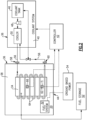
Figure 1 is a schematic view of a schematic view of an example aircraft cryogenic fuel system. -
Figure 2 is a schematic view of the example aircraft cryogenic fuel system. -
Figure 1 schematically illustrates anaircraft 20 that includes acryogenic fuel system 32 and a cryogenicfuel tank assembly 34. Acooling system 36 is configured to maintain a temperature within a predefined range when theaircraft 20 is in a non-operating condition, such as when parked at an airport gate or for maintenance. Repeated thermal cycling between ambient and cryogenic temperatures can reduce operational life of thefuel tank assembly 34. Theexample cooling system 36 maintains thefuel tank assembly 34 at temperatures that maintain cryogenic conditions needed to maintain the fuel in a liquid phase. Moreover, theexample cooling system 36 may also operate to reduce or eliminate thermal cycling of thefuel tank assembly 34 when empty. - Maintaining the cryogenic fuel in liquid form requires systems to maintain temperatures well below ambient temperatures. Even with such cryogenic systems, some amount of the liquid fuel changes phase into a gaseous form. The
aircraft fuel system 32 distributes fuel to theengines 22 and includes features that accommodate and use the gaseous fuel during aircraft operation. However, when the aircraft is in a non-flight condition or not operating such as during passenger loading and unloading and any other extended period of non-flight operation or down time, the cryogenic fuel will boil off at some rate. Depending on ambient conditions and the duration of the down time, losses of fuel due to transformation of the liquid fuel to gaseous form can be significant. - Additionally, the cryogenic
fuel tank assembly 34 operates at temperatures sufficiently low to maintain the fuel in a liquid form. For example, for a liquid hydrogen fuel, thefuel tank assembly 34 will operate to maintain the fuel at temperatures below -252 °C (-422 °F) at 1 bar pressure. The temperature may be -245 °C (-409 °F) at other realistic operating pressures. Other fuels require different temperature ranges to maintain fuel in the liquid form. Moreover, cryogenic temperatures are considered as temperature below -153°C (-243 °F). During normal aircraft operation, the operating temperature of thefuel tank assembly 34 does not fluctuate dramatically. Maintaining the lower temperature requires energy input to operate thecooling system 34. In some instances, during extended periods of down time, fuel may be removed from thefuel tank assembly 34 and saved in an off-planefuel storage tank 52. - Without fuel present, the
fuel tank assembly 34 does not need to maintain the cryogenic temperatures required for the fuel. However, permitting thefuel tank assembly 34 to warm to ambient temperatures followed by cooling back to cryogenic temperatures induces thermal cycle stresses and strains that may reduce operational life. Accordingly, theexample cooling system 36 provides for maintaining thefuel tank assembly 34 within a predefined temperature range that limits thermal cycling. During such non-flight conditions wherein, thefuel tank assembly 34 does not contain fuel, the temperatures maybe maintained at around -100 °C (-148°F). The disclosed temperature ranges are provided by way of example and different temperatures may be appropriate for different fuels and configurations and are within the contemplation of this disclosure. - The
example aircraft 22 includes cryogenic fueledturbine engines 22. Each of theturbine engines 22 include afan section 24, acompressor section 26, a combustor section 28 and a turbine section 30 in flow series. Inlet air is compressed in thecompressor section 26 and communicated to the combustor section 28 for mixing with a cryogenic fuel and ignited to generate a high energy gas flow that expands through the turbine section 30 to drive thecompressor 26 and thefan 24. - Although an
example turbine engine 22 is shown schematically by way of example, other turbine engine architectures could be utilized and are within the contemplation of this disclosure. Moreover, the configuration of theaircraft 20 is shown by way of example and other aircraft configurations could be utilized and are within the contemplation of this disclosure. - In one example embodiment, the cryogenic fuel is a hydrogen-based fuel. The hydrogen-based fuel may be hydrogen and/or be derived from hydrogen containing compounds such as ammonia. In another example embodiment, the cryogenic fuel is a liquid natural gas. It should be appreciated that although hydrogen, ammonia and liquid natural gas are disclosed by way of example, other cryogenic fuels could be utilized and are within the scope and contemplation of this disclosure.
- The cryogenic
fuel tank assembly 34 stores fuel onboard theaircraft 20 in liquid form. During downtime where the aircraft is not operating, theexample cooling system 36 maintains thefuel tank assembly 34 within a predefined temperature range. If fuel remains within thefuel tank assembly 34, the temperature range is within limits determined to maintain the fuel in the liquid form and prevent and/or reduce boil off. - If fuel has been removed from the
fuel tank assembly 34, such as moved to the ground basedfuel storage tank 52, the predefined temperature range will include limits that reduce thermal cycling. In one example embodiment, the predefined temperature range includes a lower limit that is greater than that needed to maintain fuel in a liquid state. Because no fuel is present, the temperature need not be maintained at such low temperatures, but only to temperatures determined to limit thermal cycling. - Referring to
Figure 2 with continued reference toFigure 1 , theexample cooling system 36 is configured to operate when theaircraft 20 is not operating and therefore not generating power for an extended period. Thecooling system 36 includes anaircraft portion 38 that is mounted within theaircraft 20 and aground portion 40. Theaircraft portion 38 includes thefuel tank assembly 34 that includes a plurality ofconduits 64 for circulating acoolant 56 to maintain a desired temperature of thefuel tank assembly 34. The ground basedportion 40 includes atank 46 for coolant, apump 48 and acoolant circulation system 50. - An
inlet 58 and anoutlet 60 are provided on theaircraft 20 to couple theaircraft portion 38 to theground portion 40. Theinlet 58 andoutlet 60 provide for the flow ofcoolant 56 to theconduits 64 associated with thefuel tank assembly 34. Thecoolant circulation system 50 includes devices and structures for operation of a refrigerant cycle for maintaining the flow ofcoolant 56 at temperatures and pressures determined to keep thefuel tank assembly 34 within a desired temperature range. - In one example embodiment, the
conduits 64 are filled withcoolant 56 during aircraft operation. Thecoolant 56 within theconduits 64 may be utilized for cooling of thefuel tank assembly 34 during aircraft operation. Alternatively, thecoolant 56 may simply be stored in theconduits 64 and only circulated when coupled to the ground basedportion 40. - In another example embodiment,
coolant 56 is emptied from theconduits 64 during aircraft operations and filled once coupled to the ground basedportion 40. In such an example,coolant 56 from thecoolant tank 46 is pumped through thecoolant circulation system 50 and into theconduits 64. Once theconduits 64 are filled, thecoolant 56 is circulated through theaircraft portion 38 and theground portion 40 to maintain thefuel tank assembly 34 at desired temperatures. - A
controller 42 is provided that controls operation to maintain the desired temperature of thefuel tank assembly 34. One or more sensors schematically indicated at 62 maybe associated with thefuel tank assembly 34 to provide temperature information to thecontroller 42. Other sensors system(s), schematically indicated at 66 may provide other information indicative of conditions of thefuel tank assembly 34 and/or of fuel stored within thefuel tank assembly 34. For example, a pressure of fuel within the fuel tank assembly may be communicated to the controller. Additionally, surface temperatures of portions of thefuel tank assembly 34 may be gathered and utilized to tailor cooling flow when thefuel tank assembly 34 is empty of fuel. - The
controller 42 is programmed to operate theaircraft portion 38 and ground basedportion 40 of theexample cooling system 36 to maintain fuel stored within the fuel tank assembly at predefined temperatures. Thecontroller 42 may also be programmed to maintain thefuel tank assembly 34 within a predefined temperature range to reduce thermal cycling when void of fuel. - The
example controller 42 is a device and system for performing necessary computing or calculation operations. Theexample controller 42 may be specially constructed for this purpose, or it may comprise at least a general-purpose computer selectively activated or reconfigured by a computer program stored in the computer. Additionally, thecontroller 42 may be a dedicated device for operation of the fuel system, or may be a program stored on an engine or aircraft controller. - The
controller 42 may include a computer program directing operation. Such a computer program and also data required for its execution may be stored in a computer readable storage medium, such as, but is not limited to, any type of disk including floppy disks, optical disks, CD-ROMs, magnetic-optical disks, read-only memories (ROMs), random access memories (RAMS), EPROMs, EEPROMs, magnetic or optical cards, application specific integrated circuits (ASICs), or any type of media suitable for storing electronic instructions, and each coupled to a computer system bus. Furthermore, the computer referred to may include a single processor or may be architectures employing multiple processor designs for increased computing capability. - In one example operational embodiment, fuel stored in the
fuel tank assembly 34 is maintained at cryogenic conditions during aircraft operation. During such aircraft operation, systems powered by aircraft power storage and/or generating systems are utilized to power thecooling system 36. Fuel is dispersed through thefuel system 32 to theengines 22 to provide for the generation of power and propulsive thrust. - Once the
aircraft 20 has landed and is no longer generating power, thecooling system 36 is powered by a ground basedpower source 54. Theaircraft 20 includes acoupling 44 for communicating power for the ground basedpower source 54 to thecooling system 36. Most power required to operate thecooling system 36 is therefore provided by the ground basedpower system 54. Theaircraft 20 may include power storage systems, such as batteries that may be utilized to partially power the cooling system. 36. - In another example operational embodiment, fuel within the aircraft mounted
fuel tank assembly 34 is offloaded into a ground basedfuel storage tank 52. In this example, the fuel is removed to the ground basedfuel storage tank 52 to reduce demands on thecooling system 36. When thefuel tank assembly 34 is empty, thecooling system 36 only needs to maintain temperatures within a range determined to limit thermal cycling. Such a temperature range may not need to be as low as required to maintain the fuel in a liquid phase. However, the temperature range will be lower than ambient conditions to reduce thermal cycling on thefuel tank assembly 34. - In another example embodiment, fuel remains within the
fuel tank assembly 34 and therefore cryogenic temperatures are maintained to hold the fuel in a liquid phase. Moreover, thefuel tank assembly 34 is maintained at temperatures determined to reduce boil off the cryogenic fuel. - In one example embodiment,
coolant 56 is stored onboard theaircraft 20 within theconduits 64. Once theaircraft 20 is idle theground portion 40 is coupled to theconduits 64 byaccessible inlet 58 andoutlet 60. Theground portion 40 includes thecoolant circulation system 50 that provides for circulation and cooling of thecoolant 56. Coolant may be added to fill the system and combined with coolant stored in the conduits. During the aircraft downtime, theground portion 40 operates to circulate coolant to maintain the temperature of thefuel tank assembly 34. - In another example embodiment, the
conduits 64 are emptied ofcoolant 56 during aircraft operation. Once theaircraft 20 is parked, theconduits 64 are filled withcoolant 56 from the ground basedportion 40. The ground basedportion 40 includes thecoolant tank 46 for storing coolant needed to fill the conduits. Accordingly, once the ground basedportion 40 is coupled to theconduits 64,coolant 56 fills the conduits and begins circulating to maintain thefuel tank assembly 34 within the desired temperature range. - Operation of the ground based
portion 40 in concert with theaircraft portion 38 is governed by thecontroller 42 based on information indicative of conditions of thefuel tank assembly 34.Sensor systems controller 42 that is utilized to tailor operation of the ground based system. The information provided to thecontroller 42 may include the temperature information of fuel within thetank assembly 34, the temperature of thetank assembly 34 itself, pressures or any other measurement that provides an indication of tank conditions that are useful for maintaining thetank assembly 34 within temperature within a desired range. - When the
aircraft 20 is ready to resume operation, the ground basedportion 40 is decoupled from theaircraft portion 38. In one example embodiment, decoupling of the ground basedportion 40 includes removing coolant from theconduits 64 associated with thetank assembly 34. In another example embodiment, decoupling of the ground basedportion 40 includes leaving coolant within theconduits 64. Once the ground basedportion 40 is decoupled, operation of thefuel tank assembly 34 is taken over by aircraft powered systems. - Accordingly, the disclosed example cryogenic fuel system maintains fuel tank conditions during aircraft downtime utilizing ground based systems. Moreover, the disclosed example cryogenic fuel system maintains a temperature within a predefined range to either maintain fuel in a desired phase or to reduce thermal cycling of the fuel tank assembly.
- Although an example embodiment has been disclosed, a worker of ordinary skill in this art would recognize that certain modifications would come within the scope of this disclosure. For that reason, the following claims should be studied to determine the scope and content of this disclosure.
Claims (15)
- A cryogenic fuel system (32) for an aircraft (20), the cryogenic fuel system (32) comprising:a fuel tank assembly (34) configured to store a cryogenic fuel in a liquid phase during aircraft operation; anda cooling system (36) associated with the fuel tank assembly (34), the cooling system (36) configured to maintain the fuel tank assembly (34) within a predefined temperature range during non-flight operation.
- The cryogenic fuel system (32) of claim 1, wherein the cooling system (36) includes a coupling (44) to a ground based power source (54).
- The cryogenic fuel system (32) of claim 1 or 2, wherein the cooling system (36) is operable independent of power generated on the aircraft (20).
- The cryogenic fuel system (32) of any preceding claim, wherein the fuel tank assembly (34) includes a network of conduits (64) for a coolant (56) utilized to maintain the temperature of the fuel tank assembly (34) within the predefined temperature range.
- The cryogenic fuel system (32) of claim 4, including an inlet (58) for filling the network of conduits (64) with the coolant (56), wherein the network of conduits (64) are fillable with coolant (56) through the inlet (58) during non-flight operation.
- The cryogenic fuel system (32) of claim 4 or 5, wherein the network of conduits (64) contain the coolant (56) during aircraft operation.
- The cryogenic fuel system (32) of any of claims 4 to 6, wherein the cooling system (36) includes an aircraft located portion (38) and a ground based portion (40), the ground based portion (40) includes devices configured to circulate the coolant (56) within the network of conduits (64).
- The cryogenic fuel system (32) of any preceding claim, wherein the cooling system (36) is configured to maintain a temperature of the fuel tank assembly (34) independent of whether the fuel tank assembly (34) is filled with fuel or is empty.
- The cryogenic fuel system (32) of any preceding claim, wherein the predefined temperature range includes an upper limit that is below a temperature required for maintaining the cryogenic fuel in the liquid phase.
- An aircraft propulsion system comprising:a turbine engine (22) configured to generate propulsive thrust utilizing a cryogenically stored fuel; anda cryogenic fuel system (32) as claimed in any preceding claim.
- A method of operating a cryogenic fuel system (32) for an aircraft (20), the method comprising:storing a fuel in a fuel tank assembly (34) at a cryogenic condition for use during aircraft operation;powering a cooling system (36) associated with the fuel tank assembly (34) during non-flight operation; andcirculating a coolant (56) within a network of conduits (64) associated with the fuel tank assembly (34) utilizing a ground based system to maintain the fuel tank assembly (34) within a predefined temperature range during non-flight operation.
- The method of claim 11, including filling the network of conduits (64) with the coolant (56) from the ground based system during non-flight operation.
- The cryogenic fuel system of any of claims 1 to 9, or the apparatus of claim 10, or the method of claim 11 or 12, wherein the predefined temperature range includes a lower limit above the temperature required for maintaining the cryogenic fuel in the liquid phase.
- The method of any of claims 11 to 13, including removing the fuel from the fuel tank assembly (34) during non-flight operation and maintaining the fuel tank assembly (34) within the predefined temperature range once the fuel removed from the fuel tank assembly (34).
- The method of any of claims 11 to 14, wherein the predefined temperature range includes a lower limit determined to reduce boil off of fuel within the fuel tank assembly (34).
Applications Claiming Priority (1)
| Application Number | Priority Date | Filing Date | Title |
|---|---|---|---|
| US18/300,594 US20240343408A1 (en) | 2023-04-14 | 2023-04-14 | Cooling of aircraft cryogenic fuel tank assembly |
Publications (1)
| Publication Number | Publication Date |
|---|---|
| EP4446236A1 true EP4446236A1 (en) | 2024-10-16 |
Family
ID=90730358
Family Applications (1)
| Application Number | Title | Priority Date | Filing Date |
|---|---|---|---|
| EP24170113.5A Pending EP4446236A1 (en) | 2023-04-14 | 2024-04-12 | Cooling of aircraft cryogenic fuel tank assembly |
Country Status (2)
| Country | Link |
|---|---|
| US (1) | US20240343408A1 (en) |
| EP (1) | EP4446236A1 (en) |
Citations (8)
| Publication number | Priority date | Publication date | Assignee | Title |
|---|---|---|---|---|
| DE3911655C1 (en) * | 1989-04-10 | 1990-06-07 | Messerschmitt-Boelkow-Blohm Gmbh, 8012 Ottobrunn, De | Cryogenic supersonic aircraft fuel tank - is surrounded by fuel pipe harness to permit heating or cooling |
| CN103234112A (en) * | 2013-04-26 | 2013-08-07 | 北京航空航天大学 | Mobile low-temperature liquefied gas storage system |
| US20150337730A1 (en) * | 2012-12-28 | 2015-11-26 | General Electric Company | Turbine engine assemblies |
| US20160025339A1 (en) * | 2013-03-15 | 2016-01-28 | General Electric Company | Energy-efficient and controlled vaporization of cryofuels for aircraft engines |
| DE102015215066A1 (en) * | 2015-08-06 | 2017-02-09 | Bayerische Motoren Werke Aktiengesellschaft | Method for operating a fuel cell system of a motor vehicle |
| CN109969411A (en) * | 2018-12-31 | 2019-07-05 | 北京航空航天大学 | An aircraft fuel thermal management system and method with cold storage capability |
| CN110043791A (en) * | 2019-04-30 | 2019-07-23 | 成都深冷科技有限公司 | The device and method of liquid hydrogen storage tank evaporation rate is reduced using liquid nitrogen cooling capacity |
| WO2022084432A1 (en) * | 2020-10-23 | 2022-04-28 | Ic Technology As | Improved cryogenic storage tank with an integrated closed cooling system |
Family Cites Families (3)
| Publication number | Priority date | Publication date | Assignee | Title |
|---|---|---|---|---|
| JP2016508912A (en) * | 2012-12-28 | 2016-03-24 | ゼネラル・エレクトリック・カンパニイ | Method for managing LNG boil-off and management assembly for LNG boil-off |
| ES2933078A1 (en) * | 2021-07-27 | 2023-01-31 | Airbus Operations Slu | AIRCRAFT WITH HYDROGEN TANK (Machine-translation by Google Translate, not legally binding) |
| US12479402B2 (en) * | 2022-04-06 | 2025-11-25 | Cummins Inc. | Fuel refilling system and method for equipment powered by fuel |
-
2023
- 2023-04-14 US US18/300,594 patent/US20240343408A1/en active Pending
-
2024
- 2024-04-12 EP EP24170113.5A patent/EP4446236A1/en active Pending
Patent Citations (8)
| Publication number | Priority date | Publication date | Assignee | Title |
|---|---|---|---|---|
| DE3911655C1 (en) * | 1989-04-10 | 1990-06-07 | Messerschmitt-Boelkow-Blohm Gmbh, 8012 Ottobrunn, De | Cryogenic supersonic aircraft fuel tank - is surrounded by fuel pipe harness to permit heating or cooling |
| US20150337730A1 (en) * | 2012-12-28 | 2015-11-26 | General Electric Company | Turbine engine assemblies |
| US20160025339A1 (en) * | 2013-03-15 | 2016-01-28 | General Electric Company | Energy-efficient and controlled vaporization of cryofuels for aircraft engines |
| CN103234112A (en) * | 2013-04-26 | 2013-08-07 | 北京航空航天大学 | Mobile low-temperature liquefied gas storage system |
| DE102015215066A1 (en) * | 2015-08-06 | 2017-02-09 | Bayerische Motoren Werke Aktiengesellschaft | Method for operating a fuel cell system of a motor vehicle |
| CN109969411A (en) * | 2018-12-31 | 2019-07-05 | 北京航空航天大学 | An aircraft fuel thermal management system and method with cold storage capability |
| CN110043791A (en) * | 2019-04-30 | 2019-07-23 | 成都深冷科技有限公司 | The device and method of liquid hydrogen storage tank evaporation rate is reduced using liquid nitrogen cooling capacity |
| WO2022084432A1 (en) * | 2020-10-23 | 2022-04-28 | Ic Technology As | Improved cryogenic storage tank with an integrated closed cooling system |
Also Published As
| Publication number | Publication date |
|---|---|
| US20240343408A1 (en) | 2024-10-17 |
Similar Documents
| Publication | Publication Date | Title |
|---|---|---|
| US12422103B2 (en) | Device for regulating the pressure of an aircraft cryogenic fuel tank | |
| US9255664B2 (en) | Cryogenic fuel system with auxiliary power provided by boil-off gas | |
| US5899085A (en) | Integrated air conditioning and power unit | |
| US6845630B2 (en) | Electric power and cooling system for an aircraft | |
| US20130192246A1 (en) | Dual fuel aircraft engine control system and method for operating same | |
| US8480460B2 (en) | Cabin air supercharged aircraft internal combustion engine | |
| US10184614B2 (en) | Method for managing LNG boil-off and LNG boil-off management assembly | |
| US20130186059A1 (en) | Dual fuel aircraft system and method for operating same | |
| US10822103B2 (en) | Propulsor assembly for an aircraft | |
| CN105026268A (en) | Energy-efficient and controlled vaporization of cryogenic fuels for aircraft engines | |
| JPH09184452A (en) | High density liquid propellant | |
| JP2016509645A (en) | Temperature and actuation control system and method for controlling aircraft fluid temperature | |
| EP3575216B1 (en) | Air supply management system for auxiliary power unit | |
| EP4393825A1 (en) | Fuel conditioning system | |
| EP4303417B1 (en) | Hybrid electric hydrogen engine for aircraft | |
| EP4446236A1 (en) | Cooling of aircraft cryogenic fuel tank assembly | |
| US20240369021A1 (en) | System for conditioning fuel for supplying an aircraft turbomachine, aircraft and method of use | |
| JP2019056347A (en) | Fuel supply system and fuel supply method | |
| US20240254927A1 (en) | Reliquification of boil off gas at airport gate | |
| US20260055726A1 (en) | Water injection system for performance and durability augmentation with selectively utilized water tank | |
| EP4406854B1 (en) | Cryogenic fuel boil off powered fuel cell | |
| US20260078697A1 (en) | H2o performance and durability augmentation | |
| US12509246B2 (en) | Collection of boil off gas at airport gate | |
| EP4647591A1 (en) | Aircraft fuel system and method | |
| Bailey et al. | System evaluation of a non-toxic upgrade for Shuttle OMS/RCS |
Legal Events
| Date | Code | Title | Description |
|---|---|---|---|
| PUAI | Public reference made under article 153(3) epc to a published international application that has entered the european phase |
Free format text: ORIGINAL CODE: 0009012 |
|
| STAA | Information on the status of an ep patent application or granted ep patent |
Free format text: STATUS: THE APPLICATION HAS BEEN PUBLISHED |
|
| AK | Designated contracting states |
Kind code of ref document: A1 Designated state(s): AL AT BE BG CH CY CZ DE DK EE ES FI FR GB GR HR HU IE IS IT LI LT LU LV MC ME MK MT NL NO PL PT RO RS SE SI SK SM TR |
|
| STAA | Information on the status of an ep patent application or granted ep patent |
Free format text: STATUS: REQUEST FOR EXAMINATION WAS MADE |
|
| 17P | Request for examination filed |
Effective date: 20250415 |
|
| STAA | Information on the status of an ep patent application or granted ep patent |
Free format text: STATUS: EXAMINATION IS IN PROGRESS |
|
| 17Q | First examination report despatched |
Effective date: 20251106 |