EP4446234A1 - Multi-directional baffles for aircraft fuel tanks - Google Patents
Multi-directional baffles for aircraft fuel tanks Download PDFInfo
- Publication number
- EP4446234A1 EP4446234A1 EP24164682.7A EP24164682A EP4446234A1 EP 4446234 A1 EP4446234 A1 EP 4446234A1 EP 24164682 A EP24164682 A EP 24164682A EP 4446234 A1 EP4446234 A1 EP 4446234A1
- Authority
- EP
- European Patent Office
- Prior art keywords
- baffle
- baffles
- fuel
- tank
- cryogenic
- Prior art date
- Legal status (The legal status is an assumption and is not a legal conclusion. Google has not performed a legal analysis and makes no representation as to the accuracy of the status listed.)
- Pending
Links
Images






Classifications
-
- B—PERFORMING OPERATIONS; TRANSPORTING
- B64—AIRCRAFT; AVIATION; COSMONAUTICS
- B64D—EQUIPMENT FOR FITTING IN OR TO AIRCRAFT; FLIGHT SUITS; PARACHUTES; ARRANGEMENT OR MOUNTING OF POWER PLANTS OR PROPULSION TRANSMISSIONS IN AIRCRAFT
- B64D37/00—Arrangements in connection with fuel supply for power plant
- B64D37/02—Tanks
- B64D37/06—Constructional adaptations thereof
-
- B—PERFORMING OPERATIONS; TRANSPORTING
- B64—AIRCRAFT; AVIATION; COSMONAUTICS
- B64D—EQUIPMENT FOR FITTING IN OR TO AIRCRAFT; FLIGHT SUITS; PARACHUTES; ARRANGEMENT OR MOUNTING OF POWER PLANTS OR PROPULSION TRANSMISSIONS IN AIRCRAFT
- B64D37/00—Arrangements in connection with fuel supply for power plant
- B64D37/02—Tanks
- B64D37/06—Constructional adaptations thereof
- B64D37/08—Internal partitioning
-
- B—PERFORMING OPERATIONS; TRANSPORTING
- B60—VEHICLES IN GENERAL
- B60K—ARRANGEMENT OR MOUNTING OF PROPULSION UNITS OR OF TRANSMISSIONS IN VEHICLES; ARRANGEMENT OR MOUNTING OF PLURAL DIVERSE PRIME-MOVERS IN VEHICLES; AUXILIARY DRIVES FOR VEHICLES; INSTRUMENTATION OR DASHBOARDS FOR VEHICLES; ARRANGEMENTS IN CONNECTION WITH COOLING, AIR INTAKE, GAS EXHAUST OR FUEL SUPPLY OF PROPULSION UNITS IN VEHICLES
- B60K15/00—Arrangement in connection with fuel supply of combustion engines or other fuel consuming energy converters, e.g. fuel cells; Mounting or construction of fuel tanks
- B60K15/03—Fuel tanks
- B60K15/077—Fuel tanks with means modifying or controlling distribution or motion of fuel, e.g. to prevent noise, surge, splash or fuel starvation
-
- B—PERFORMING OPERATIONS; TRANSPORTING
- B64—AIRCRAFT; AVIATION; COSMONAUTICS
- B64D—EQUIPMENT FOR FITTING IN OR TO AIRCRAFT; FLIGHT SUITS; PARACHUTES; ARRANGEMENT OR MOUNTING OF POWER PLANTS OR PROPULSION TRANSMISSIONS IN AIRCRAFT
- B64D37/00—Arrangements in connection with fuel supply for power plant
- B64D37/02—Tanks
-
- B—PERFORMING OPERATIONS; TRANSPORTING
- B64—AIRCRAFT; AVIATION; COSMONAUTICS
- B64D—EQUIPMENT FOR FITTING IN OR TO AIRCRAFT; FLIGHT SUITS; PARACHUTES; ARRANGEMENT OR MOUNTING OF POWER PLANTS OR PROPULSION TRANSMISSIONS IN AIRCRAFT
- B64D37/00—Arrangements in connection with fuel supply for power plant
- B64D37/30—Fuel systems for specific fuels
-
- B—PERFORMING OPERATIONS; TRANSPORTING
- B65—CONVEYING; PACKING; STORING; HANDLING THIN OR FILAMENTARY MATERIAL
- B65D—CONTAINERS FOR STORAGE OR TRANSPORT OF ARTICLES OR MATERIALS, e.g. BAGS, BARRELS, BOTTLES, BOXES, CANS, CARTONS, CRATES, DRUMS, JARS, TANKS, HOPPERS, FORWARDING CONTAINERS; ACCESSORIES, CLOSURES, OR FITTINGS THEREFOR; PACKAGING ELEMENTS; PACKAGES
- B65D90/00—Component parts, details or accessories for large containers
- B65D90/52—Anti-slosh devices
-
- F—MECHANICAL ENGINEERING; LIGHTING; HEATING; WEAPONS; BLASTING
- F02—COMBUSTION ENGINES; HOT-GAS OR COMBUSTION-PRODUCT ENGINE PLANTS
- F02M—SUPPLYING COMBUSTION ENGINES IN GENERAL WITH COMBUSTIBLE MIXTURES OR CONSTITUENTS THEREOF
- F02M21/00—Apparatus for supplying engines with non-liquid fuels, e.g. gaseous fuels stored in liquid form
- F02M21/02—Apparatus for supplying engines with non-liquid fuels, e.g. gaseous fuels stored in liquid form for gaseous fuels
- F02M21/0218—Details on the gaseous fuel supply system, e.g. tanks, valves, pipes, pumps, rails, injectors or mixers
- F02M21/0221—Fuel storage reservoirs, e.g. cryogenic tanks
-
- F—MECHANICAL ENGINEERING; LIGHTING; HEATING; WEAPONS; BLASTING
- F15—FLUID-PRESSURE ACTUATORS; HYDRAULICS OR PNEUMATICS IN GENERAL
- F15D—FLUID DYNAMICS, i.e. METHODS OR MEANS FOR INFLUENCING THE FLOW OF GASES OR LIQUIDS
- F15D1/00—Influencing flow of fluids
- F15D1/0005—Baffle plates
-
- B—PERFORMING OPERATIONS; TRANSPORTING
- B60—VEHICLES IN GENERAL
- B60K—ARRANGEMENT OR MOUNTING OF PROPULSION UNITS OR OF TRANSMISSIONS IN VEHICLES; ARRANGEMENT OR MOUNTING OF PLURAL DIVERSE PRIME-MOVERS IN VEHICLES; AUXILIARY DRIVES FOR VEHICLES; INSTRUMENTATION OR DASHBOARDS FOR VEHICLES; ARRANGEMENTS IN CONNECTION WITH COOLING, AIR INTAKE, GAS EXHAUST OR FUEL SUPPLY OF PROPULSION UNITS IN VEHICLES
- B60K15/00—Arrangement in connection with fuel supply of combustion engines or other fuel consuming energy converters, e.g. fuel cells; Mounting or construction of fuel tanks
- B60K15/03—Fuel tanks
- B60K2015/03328—Arrangements or special measures related to fuel tanks or fuel handling
- B60K2015/0344—Arrangements or special measures related to fuel tanks or fuel handling comprising baffles
-
- B—PERFORMING OPERATIONS; TRANSPORTING
- B60—VEHICLES IN GENERAL
- B60K—ARRANGEMENT OR MOUNTING OF PROPULSION UNITS OR OF TRANSMISSIONS IN VEHICLES; ARRANGEMENT OR MOUNTING OF PLURAL DIVERSE PRIME-MOVERS IN VEHICLES; AUXILIARY DRIVES FOR VEHICLES; INSTRUMENTATION OR DASHBOARDS FOR VEHICLES; ARRANGEMENTS IN CONNECTION WITH COOLING, AIR INTAKE, GAS EXHAUST OR FUEL SUPPLY OF PROPULSION UNITS IN VEHICLES
- B60K15/00—Arrangement in connection with fuel supply of combustion engines or other fuel consuming energy converters, e.g. fuel cells; Mounting or construction of fuel tanks
- B60K15/03—Fuel tanks
- B60K15/077—Fuel tanks with means modifying or controlling distribution or motion of fuel, e.g. to prevent noise, surge, splash or fuel starvation
- B60K2015/0775—Fuel tanks with means modifying or controlling distribution or motion of fuel, e.g. to prevent noise, surge, splash or fuel starvation for reducing movement or slash noise of fuel
-
- F—MECHANICAL ENGINEERING; LIGHTING; HEATING; WEAPONS; BLASTING
- F17—STORING OR DISTRIBUTING GASES OR LIQUIDS
- F17C—VESSELS FOR CONTAINING OR STORING COMPRESSED, LIQUEFIED OR SOLIDIFIED GASES; FIXED-CAPACITY GAS-HOLDERS; FILLING VESSELS WITH, OR DISCHARGING FROM VESSELS, COMPRESSED, LIQUEFIED, OR SOLIDIFIED GASES
- F17C2270/00—Applications
- F17C2270/01—Applications for fluid transport or storage
- F17C2270/0186—Applications for fluid transport or storage in the air or in space
- F17C2270/0189—Planes
-
- Y—GENERAL TAGGING OF NEW TECHNOLOGICAL DEVELOPMENTS; GENERAL TAGGING OF CROSS-SECTIONAL TECHNOLOGIES SPANNING OVER SEVERAL SECTIONS OF THE IPC; TECHNICAL SUBJECTS COVERED BY FORMER USPC CROSS-REFERENCE ART COLLECTIONS [XRACs] AND DIGESTS
- Y02—TECHNOLOGIES OR APPLICATIONS FOR MITIGATION OR ADAPTATION AGAINST CLIMATE CHANGE
- Y02E—REDUCTION OF GREENHOUSE GAS [GHG] EMISSIONS, RELATED TO ENERGY GENERATION, TRANSMISSION OR DISTRIBUTION
- Y02E60/00—Enabling technologies; Technologies with a potential or indirect contribution to GHG emissions mitigation
- Y02E60/30—Hydrogen technology
- Y02E60/32—Hydrogen storage
Definitions
- This disclosure relates generally to hydrogen aircraft fuel storage and, more particularly, to cryogenic hydrogen tank systems and methods for operating the same.
- liquid hydrogen is susceptible to boil off and bubble formation in the fuel when exposed to fuel slosh, or movement of the fuel in the cryogenic fuel tank.
- exposure to acceleration is of particular concern, as g-loads can cause the fuel to move in all degrees of freedom.
- a first part is above a second part, if the second part has at least one part between Earth and the first part.
- a first part is "below” a second part when the first part is closer to the Earth than the second part.
- a first part can be above or below a second part with one or more of: other parts therebetween, without other parts therebetween, with the first and second parts touching, or without the first and second parts being in direct contact with one another.
- any part e.g., a layer, film, area, region, or plate
- any part e.g., a layer, film, area, region, or plate
- the referenced part is either in contact with the other part, or that the referenced part is above the other part with one or more intermediate part(s) located therebetween.
- connection references may include intermediate members between the elements referenced by the connection reference and/or relative movement between those elements unless otherwise indicated. As such, connection references do not necessarily infer that two elements are directly connected and/or in fixed relation to each other. As used herein, stating that any part is in "contact” with another part is defined to mean that there is no intermediate part between the two parts.
- descriptors such as “first,” “second,” “third,” etc. are used herein without imputing or otherwise indicating any meaning of priority, physical order, arrangement in a list, and/or ordering in any way, but are merely used as labels and/or arbitrary names to distinguish elements for ease of understanding the disclosed examples.
- the descriptor "first” may be used to refer to an element in the detailed description, while the same element may be referred to in a claim with a different descriptor such as "second” or “third.” In such instances, it should be understood that such descriptors are used merely for identifying those elements distinctly that might, for example, otherwise share a same name.
- A, B, and/or C refers to any combination or subset of A, B, C such as (1) A alone, (2) B alone, (3) C alone, (4) A with B, (5) A with C, (6) B with C, or (7) A with B and with C.
- the phrase "at least one of A and B" is intended to refer to implementations including any of (1) at least one A, (2) at least one B, or (3) at least one A and at least one B.
- the phrase "at least one of A or B" is intended to refer to implementations including any of (1) at least one A, (2) at least one B, or (3) at least one A and at least one B.
- the phrase "at least one of A and B" is intended to refer to implementations including any of (1) at least one A, (2) at least one B, or (3) at least one A and at least one B.
- the phrase "at least one of A or B" is intended to refer to implementations including any of (1) at least one A, (2) at least one B, or (3) at least one A and at least one B.
- “approximately” and “about” modify their subjects/values to recognize the potential presence of variations that occur in real world applications. For example, “approximately” and “about” may modify dimensions that may not be exact due to manufacturing tolerances and/or other real world imperfections as will be understood by persons of ordinary skill in the art. For example, “approximately” and “about” may indicate such dimensions may be within a tolerance range of +/- 10% unless otherwise specified in the below description.
- the term "substantially” is used to describe a relationship between two parts that is within three degrees of the stated relationship (e.g., a substantially colinear relationship is within three degrees of being linear, a substantially perpendicular relationship is within three degrees of being perpendicular, a substantially parallel relationship is within three degrees of being parallel, etc.).
- the term "substantially constant” is used to describe the state of a temperature, pressure, or some other property that is remaining within one unit of measure of the initial value (e.g. temperature is substantially constant in spite of a change from 11.1 degrees Celsius to 11.2 degrees Celsius).
- the term "substantially similar” or “substantially equal” is used to describe a relationship between two entities that indicate that they are the same within one unit of measurement of each other (e.g. a vapor pressure 374.0 kPa is substantially equal to a saturated pressure of 374.2 kPa.
- the term “substantially simultaneous” is used to describe a relationship between two components that are acting within one second of each other (e.g. at the same time).
- the term "substantially completely" is used to describe a liquid phase of the hydrogen fuel and refers to a unit mass (e.g., one kilogram (kg), one pound (lb.), etc.) of LH2 that includes near 100% hydrogen in the liquid phase, such as at least 99%, such as at least 97.5%, such as at least 95%, such as at least 92.5%, such as at least 90%, such as at least 85%, or such as at least 75% of LH2 per unit mass.
- one unit mass of LH2 substantially completely in the liquid phase can include 95% liquid hydrogen and 5% hydrogen vapor bubbles.
- the phrase "in communication,” including variations thereof, encompasses direct communication and/or indirect communication through one or more intermediary components, and does not require direct physical (e.g., wired) communication and/or constant communication, but rather additionally includes selective communication at periodic intervals, scheduled intervals, aperiodic intervals, and/or one-time events.
- Example cryogenic hydrogen tank systems are disclosed herein.
- Example cryogenic hydrogen tanks are used to transport liquid hydrogen (LH2) and/or hydrogen vapor (gaseous hydrogen (GH2)).
- LH2 liquid hydrogen
- GH2 gaseous hydrogen
- hydrogen aircraft consume the LH2 for propulsion, requiring the storage of large amounts of LH2 or GH2.
- the liquid hydrogen Due to having six degrees of freedom of aircraft acceleration, the liquid hydrogen is susceptible to fluid movement inside a cryogenic hydrogen tank (hereinafter referred to as "sloshing") which can result in fuel boil off, bubble formation, and/or dynamic imbalance forces/moments on the aircraft transporting the liquid hydrogen.
- Hydrogen aircraft use hydrogen fuel (diatomic hydrogen) to eliminate carbon dioxide emissions relative to commercial aircraft that combust hydrocarbon fuels (e.g., Jet-A) for propulsion.
- hydrogen fuel poses a number of challenges as compared with combustible hydrocarbon liquid fuel.
- in its gaseous form hydrogen fuel has a much lower power density than Jet-A fuel.
- the volume of the liquid hydrogen (LH2) fuel is approximately four times the volume of Jet-A fuel to operate the aircraft over a given range.
- hydrogen fuel has a relatively low boiling point and must be stored at cryogenic temperatures to be maintained in the liquid phase.
- a storage tank holding liquid hydrogen cryogenically requires more space overall and has an increased weight as compared with a storage tank holding a comparable volume of Jet-A fuel.
- Ordinary or normal hydrogen gas that is liquefied includes about 25 % Parahydrogen and 75 % Orthohydrogen.
- the liquid undergoes a slow natural conversion from the ortho to the para form, liberating heat. This exothermic reaction generates heat greater than the heat of vaporization. This temperature increase can cause the LH2 to boil, hence the term "boil-off," which is used herein to describe the warming and evaporation process of contained LH2.
- Boil-off losses occur at the rate of about 1 % per hour.
- a conversion catalyst minimizes or otherwise reduces these losses and yields better than 95 % parahydrogen during liquefaction. It is assumed that liquid parahydrogen will be used as a fuel and can be stored with only nominal losses.
- the temperature of the LH2 can rise, and the LH2 can boil-off. Hydrogen vapor bubbles formed from boil-off can enter extraction flowlines with LH2 fuel and flow downstream to an LH2 pump.
- the LH2 When an example LH2 tank is refueled, the LH2 forms a first portion of the internal volume of the LH2 tank (e.g., 90%), and hydrogen vapor forms a second portion of the internal volume of the LH2 tank (e.g., 10%).
- the "vapor pressure” refers to pressure acting on the interior walls of a tank (e.g., an onboard LH2 tank) and the surface of a liquid (e.g., LH2) within the tank.
- saturated pressure refers to the vapor pressure when the LH2 and the hydrogen vapor are in equilibrium.
- the LH2 and the hydrogen vapor are in equilibrium and the vapor pressure is substantially similar to a saturated pressure at the given temperature.
- the saturated pressure is dependent on the temperature within the tank.
- the saturated pressure can be determined based on the temperature within the tank.
- the temperature can remain substantially similar over time, the evaporation and condensation rates can equalize, and the vapor pressure can become substantially similar (e.g., equal) to the saturated pressure.
- the evaporation rate of the LH2 increases and causes the vapor pressure to increase above the saturated pressure.
- the saturated pressure and the evaporation rate increase accordingly.
- the vapor pressure associated with the increased evaporation rate for example eight to twelve bar of pressure, is greater than the saturated pressure associated with the second temperature.
- the vapor pressure is kept sufficiently higher, approximately two bar higher, than the saturated pressure.
- the vapor pressure is maintained at levels that satisfy a safety threshold and an operational threshold of example tank systems disclosed herein. For example, 6 bar satisfies both thresholds of a tank system.
- cryogenic hydrogen tanks Another consideration of cryogenic hydrogen tanks is sloshing.
- a 100% full cryogenic hydrogen tank will not experience sloshing. However, when there is room for dynamic liquid movement of the liquid hydrogen, sloshing may occur.
- a g-load, or load factor based on a relationship to the force of gravity is placed on the large sized liquid tank and must be analyzed. G-loads are caused by acceleration of an example aircraft. The g-loads cause significant fluid motion to be of concern due to the large sized tank structure.
- Sloshing may have several effects on the tank due to liquid movement, as approximately one ton of liquid per tank is being sloshed or moved around.
- sloshing imposes stress concentrations on a liquid hydrogen tank shell as well as on an outer vacuum chamber.
- sloshing causes further liquid movement, which in turn mixes the liquid and vapor resulting in a temperature rise and corresponding tank pressure increase. This increase in tank temperature/pressure increases the amount of boil-off of liquid hydrogen and increases the amount of bubble formation. A greater amount of bubble formation increases the cavitation risk for the attached liquid hydrogen pump and puts further strain on a downstream phase separator when withdrawing liquid from the tank.
- sloshing creates an induced imbalance force or moment on the aircraft which may affect flight stability, lateral tanks, or other cryogenic hydrogen tanks. For these reasons, it is desired to minimize or otherwise reduce the amount of fuel slosh and hydrogen boil-off.
- a baffle In order to combat sloshing, a baffle can be used. Baffles, or structures placed within a fuel tank to reduce the fuel slosh within the fuel tank, have various designs such as ring baffles, vertical slotted baffles, horizontal porous baffles, or grid-like baffles.
- the challenge associated with creation of a baffle is reducing the weight in an aircraft, while increasing an the size and compliance of the baffle in reducing fuel slosh.
- Baffles can also be used to harness or control the reduced sloshing that can still occur in the fuel tank. Controlled sloshing provides a mixing effect that helps to reduce hydrogen stratification. Hydrogen stratification can be a concern for temperature and pressure build up, whereas sloshing tends to reduce the pressure in the tank due to the mixing of liquid and vapors.
- FIG. 1 is an illustration of an example first perspective view of an example first aircraft 100 that can include example cryogenic hydrogen tank systems disclosed herein.
- the first aircraft 100 includes a forward portion 102 and an aft portion 104 axially aligned along a centerline 106.
- the first aircraft 100 includes a fuselage 110, wings 120 attached to the fuselage 110, and an empennage 130.
- the first aircraft 100 includes a pair of wings 120, one on a port side of the first aircraft 100 (a port wing) and one on a starboard side of the first aircraft 100 (a starboard wing).
- first aircraft 100 illustrated in FIG. 1 is a commercial airplane, examples described herein can also be applicable to other types of fixed-wing aircraft, such as cargo aircraft, unmanned aerial vehicles (UAV), etc.
- UAV unmanned aerial vehicles
- the fuselage 110 includes a nose 112 and a tail 114, and the centerline extends axially between the nose 112 and the tail 114.
- the first aircraft 100 is substantially symmetric about the centerline 106.
- the first aircraft 100 can generate lift to perform flight operations when the aircraft 100 propels itself in a forward direction 115, wherein the forward direction 115 is generally aligned with the centerline 106 and points from the aft portion 104 toward the forward portion 102 of the aircraft 100.
- the first aircraft 100 illustrated in FIGS. 1 is a commercial passenger aircraft including a cockpit 116 to allow operation of the first aircraft 100.
- the first aircraft 100 also includes a passenger compartment 118 to accommodate passenger seating.
- a first cryogenic hydrogen tank 160 (“first tank 160") is placed aft of the cockpit 116 to separate the cockpit 116 from the passenger compartment 118
- a second cryogenic hydrogen tank 170 (“second tank 170") is placed aft of the passenger compartment 118 to separate the passenger compartment 118 from the empennage 130 and the tail 114.
- the first aircraft 100 is a cargo aircraft including storage bays to replace and/or accompany the passenger compartment 118.
- the first aircraft 100 also includes a propulsion system that produces a propulsive thrust required to propel the first aircraft 100 in flight, during taxiing operations, and the like.
- the propulsion system for the first aircraft 100 shown in FIG. 1 includes engines 140.
- the engines 140 are attached to the wings 120 by pylons 122 in an under-wing configuration.
- the engines 140 can have alternative configurations and/or can be coupled to other portions of the first aircraft 100.
- the engines 140 can additionally or alternatively include one or more engines (e.g., engines 140) coupled to other parts of the first aircraft 100, such as, for example, the empennage 130 and the fuselage 110.
- the wings 120 are attached to the fuselage 110 at example attachment points 124. As the first aircraft 100 is propelled through the air, the wings 120 generate lift and the resultant lift acts on the first aircraft 100 at a wing center of lift (described below), sometimes also referred to as a center of pressure.
- a wing center of lift (described below), sometimes also referred to as a center of pressure.
- the engines 140 shown in FIG. 1 are hydrogen turbine engines that are each capable of selectively generating a propulsive thrust for the first aircraft 100.
- the amount of propulsive thrust can be controlled at least in part based on a volume of fuel provided to the hydrogen turbine engines 140 via a fuel system.
- the LH2 fuel is stored in the first cryogenic hydrogen tank 160 and the second cryogenic hydrogen tank 170.
- Example tank systems disclosed herein include a fuel delivery assembly 150 providing the fuel flow from the first tank 160 and/or the second tank 170 to the engines 140, and, more specifically, to a fuel manifold of the combustion section of the turbomachine of the hydrogen turbine engines 140.
- the fuel delivery assembly 150 includes tubes, pipes, and the like, to fluidly connect the various components of example integrated tank systems to the hydrogen turbine engine 140.
- the fuel delivery assembly 150 can also include various other components and systems used to distribute LH2 fuel in example tank systems to the gas turbine engines 140, such as pumps, vaporizers, and the like.
- Example cryogenic hydrogen tank systems disclosed herein are described as including first tank 160, second tank 170, and/or other cryogenic hydrogen tanks to provide LH2 fuel to be combusted in the hydrogen turbine engines 140.
- cryogenic hydrogen tank systems disclosed herein can be used to supply LH2 and/or GH2 to other power systems, such as hydrogen fuel cells, power generators, and/or other electrical generators that rely on hydrogen fuel to function.
- Example cryogenic hydrogen tank systems disclosed herein are configured to hold the hydrogen fuel at least partially within the liquid phase and are configured to provide hydrogen fuel to the fuel delivery assembly 150 substantially completely in the liquid phase.
- the LH2 can include vapor bubbles which can flow into LH2 extraction flowlines. Such vapor bubbles can cause cavitation damage to LH2 pumps driving flow from example integrated tank systems.
- example baffle systems are included in example cryogenic hydrogen tanks disclosed herein. Such baffle systems are described in greater detail below.
- the hydrogen fuel is stored in cryogenic fuel tanks at cryogenic temperatures.
- the first and second tanks 160, 170 can store hydrogen fuel at a temperature of -253 degrees Celsius (°C) (20 Kelvin (K)) and a saturated pressure of 15 pounds per square inch (psi) to maintain the hydrogen fuel substantially completely in the liquid phase.
- storing hydrogen fuel in the liquid phase within a volume sufficient to power the first aircraft 100 over a range of a typical continental flight, international flight, overseas flight, etc. can involve larger cryogenic hydrogen tank(s) (e.g., first tank 160, second tank 170, etc.).
- FIG. 2 is a schematic illustration of a cross section of the fuselage 110 taken along line 2-2 in FIG. 1 .
- the wings 120 are configured to generate a center of lift 202.
- the first and second cryogenic hydrogen tanks 160, 170 are located entirely within the fuselage 110.
- the first and second tanks 160, 170 are located within the fuselage 110 such that the first and second tanks 160, 170 are substantially equidistant from the wing center of lift 202.
- the first aircraft 100 is symmetrical about the centerline 106, and the wing center of lift 202 is located on the centerline 106. Locating the first and second tanks 160, 170 substantially equidistant in the forward and aft directions from the wing center of lift 202 promotes the balance and stability of the aircraft 100 during flight.
- the first tank 160 defines a first center of gravity 204 and defines a moment arm M FT extending between the wing center of lift 202 and the first center of gravity 204.
- the second tank 170 defines a second center of gravity 206 and defines a moment arm M AT extending between the wing center of lift 202 and the second center of gravity 206.
- the first and second tanks 160, 170 define a third center of gravity 208.
- a position of the third center of gravity 208 is based on a combination of the first center of gravity 204 and the second center of gravity 206.
- the third center of gravity 208 is positioned aft of the wing center of lift 202.
- the third center of gravity 208 is aligned with the wing center of lift 202.
- the first tank 160 and the second tank 170 are positioned within the fuselage 110 such that the moment arms M FT , M AT are balanced when fuel levels therein are substantially similar (e.g. when both fuel tanks are half filled).
- the fuel delivery assemblies 150 are to extract LH2 from the first and second tanks 160, 170 substantially simultaneously so as not to significantly unbalance the aircraft 100.
- Such synchronization can lead to complex control systems of the fuel delivery assemblies 150.
- the first and second tanks 160, 170 cannot trim and/or redistribute fuel if fuel extraction becomes unsynchronized.
- first and second tanks 160, 170 can be included in example tank systems disclosed herein to refuel and/or extract LH2 to/from the first and second tanks 160, 170 substantially simultaneously (e.g. at the same time) without complex and/or multiple control systems for the fuel delivery assemblies 150.
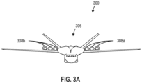
- FIG. 3A is an illustration of a front view of an example second aircraft 300 that can include example cryogenic hydrogen tanks disclosed herein.
- front view 306 shows the second aircraft 300 includes a first group of engines 308a and a second group of engines 308b.
- the second aircraft 300 includes a fuel delivery system to provide LH2 fuel from example tank systems to the first and second groups of engines 308a, 308b.
- the first and second groups of engines 308a, 308b can combust the fuel to generate a propulsive thrust and propel the second aircraft 300 in flight, during taxiing operations, and the like.
- FIG. 3A is an illustration of a front view of an example second aircraft 300 that can include example cryogenic hydrogen tanks disclosed herein.
- front view 306 shows the second aircraft 300 includes a first group of engines 308a and a second group of engines 308b.
- the second aircraft 300 includes a fuel delivery system to provide LH2 fuel from example tank systems to the first and second groups of engines 308a, 308b.
- each engine of the first and second groups of engines 308a, 308b is attached to an upper portion of the pair of wings 320 (shown in FIG. 3C ) via a pylon or some other connective structure not shown in FIGs. 3A-3C .
- the first and second groups of engines 308a, 308b are attached to the upper portion of the pair of wings 320 (shown in FIG. 3C ) in FIG. 3A
- one or more of the engines of the first and/or second groups of engines 308a, 308b can have alternative configurations and/or can be coupled to other portions of the second aircraft 300.
- the first and second groups of engines 308a, 308b illustrated in FIG. 3A are hydrogen turbine engines that are each able to selectively generate a propulsive thrust for the second aircraft 300.
- the amount of propulsive thrust can be controlled at least in part based on a volume of liquid hydrogen (LH2) fuel provided to the first and second groups of engines 308a, 308b via an example fuel delivery system.
- LH2 liquid hydrogen
- the fuel delivery system is not illustrated in FIGs. 3A-3C
- the fuel delivery system included in the second aircraft 300 can include elements (e.g., the fuel delivery assembly 150) that are substantially similar to those illustrated in FIGS. 1 and/or 2.
- FIG. 3B is an illustration of the same example second aircraft 300 from a side view.
- side view 304 shows the aircraft that can include example cryogenic hydrogen tanks disclosed herein.
- the second aircraft 300 shown in FIG. 3B is a commercial passenger aircraft, examples described herein can also be applicable to other fixed-wing aircraft, including cargo aircraft, unmanned aerial vehicles (UAV), hypersonic launch vehicles, etc.
- UAV unmanned aerial vehicles
- FIG. 3C is an illustration of a top view of the example second aircraft 300 that can include example cryogenic hydrogen tanks disclosed herein.
- the example top-down view 302 is intended to show placements and/or locations of various elements of the second aircraft 300 relative to such a view but not intended to illustrate a cross-sectional view of the second aircraft 300.
- the second aircraft 300 illustrated in FIG. 3C is substantially symmetric about a centerline 310 and includes a fuselage 312 and an empennage 314.
- the example centerline 310 extends from a nose 316 to a tail 318 of the second aircraft 300.
- the second aircraft 300 includes wings 320 attached to the fuselage 312, wherein one wing is positioned on a port side of the second aircraft 300 (a port wing), and another wing is positioned on a starboard side of the second aircraft 300 (a starboard wing).
- the wings 320 generate lift and the resultant lift acts on the second aircraft 300 at a wing center of lift 321, sometimes also referred to as a center of pressure.
- the example second aircraft 300 also includes stabilizers 322 attached to the empennage 314, wherein one stabilizer is positioned on the port side of the second aircraft 300 (a port stabilizer), and another stabilizer is positioned on the starboard side of the second aircraft 300 (a starboard stabilizer). As illustrated in FIG. 3 , a forward direction (toward the nose 316), an aft direction (toward the tail 318), a port direction (toward the left side of FIG. 3 ), and a starboard direction (toward the right side of FIG. 3 ) are associated with the second aircraft 300.
- Example cryogenic hydrogen tank systems disclosed herein can store LH2 fuel in a first group of cryogenic hydrogen tanks 324 ("first group of tanks 324") and a second group of cryogenic hydrogen tanks 326 ("second group of tanks 326").
- the first group of tanks 324 includes a first tank 324a, a second tank 324b, and a third tank 324c.
- the second group of tanks 326 includes a fourth tank 326a, a fifth tank 326b, and a sixth tank 326c.
- the tanks 324a-324c, 326a-326c are substantially similar to the first and second tanks 160, 170 described in connection with FIGS. 1 and 2 .
- the first and second groups of tanks 324, 326 are located entirely within the fuselage 312.
- the first and fourth tanks 324a, 326a are positioned forward of the second and fifth tanks 324b, 326b.
- the third and sixth tanks 324c, 326c are positioned aft of the second and fifth tanks 324b, 326b.
- each of the first tank 324a defines a first center of gravity 328a
- the second tank 324b defines a second center of gravity 328b
- the third tank 324c defines a third center of gravity 328c
- the fourth tank 326a defines a fourth center of gravity 330a
- the fifth tank 326b defines a fifth center of gravity 330b
- the sixth tank 326c defines a sixth center of gravity 330c.
- the second center of gravity 328b, the fifth center of gravity 330b, and the wing center of lift 321 are substantially aligned along a reference line 332 oriented transverse (or substantially perpendicular) to the centerline 310.
- the first and second groups of tanks 324, 326 are located in the fuselage 312 such that, relative to the forward and aft directions, the first, third, fourth, and sixth centers of gravity 328a, 328c, 330a, 330c are substantially equidistant from the wing center of lift 321. Similarly, relative to the port and starboard directions, the first, third, fourth, and sixth centers of gravity 328a, 328c, 330a, 330c are substantially equidistant from the centerline 310.
- An example forward tank moment arm, M FT extends from the wing center of lift 321 to the centers of gravity of the two forward tanks
- an example aft tank moment arm, M AT extends from the wing center of lift 321 to the centers of gravity of the two aft tanks.
- the first and second groups of tanks 324, 326 define a seventh center of gravity 334.
- a position of the seventh center of gravity 334 is based on a combination of the first, second, third, fourth, fifth, and sixth centers of gravity 228a-228c, 230a-230c.
- the seventh center of gravity 334 is positioned aft of the wing center of lift 321.
- the seventh center of gravity 334 is aligned with the wing center of lift 321.
- the second aircraft 300 illustrated in FIGs. 3A-3C is a commercial passenger aircraft similar to the first aircraft shown in FIG. 1 .
- the first and second groups of tanks 324, 326 include six tanks, the second aircraft 300 has a longer range than the first aircraft 100 ( FIGS. 1 and 2 ).
- more cryogenic tanks are included rather than developing one larger onboard tank. Having multiple cryogenic tanks distributes fuel weight more evenly throughout the fuselage 312 than a single tank.
- the second aircraft 300 can pitch up to an angle of attack (e.g., 10 degrees, 15 degrees, etc.). If the second aircraft 300 included one onboard tank to carry the same fuel capacity as six individual tanks, the majority of the LH2 would transfer behind the wing center of lift 321 during takeoff, move a center of gravity of the one onboard tank in the aft direction, and impart some undesirable instability to the second aircraft 300.
- an angle of attack e.g. 10 degrees, 15 degrees, etc.
- the second aircraft 300 includes six tanks, the respective centers of gravity 328a-328c, 330a-330c would not shift as significantly in the aft direction during takeoff relative to the example singular onboard tank, thus allowing the second aircraft 300 to maintain controllability and stability during most stages of flight (e.g., takeoff, cruise, landing, etc.).
- hydrogen aircraft e.g., the first and/or second hydrogen aircraft 100 ( FIGS. 1 and 2 ), 300 ( FIGS. 3A-3C )
- multiple cryogenic hydrogen tanks e.g., two, three, six, etc.
- the refueling process for multiple individual tanks includes connecting a refueling flowline to a first tank, filling the first tank to capacity with LH2, disconnecting the refueling flowline, purging the refueling flowline, connecting the refueling flowline to a second tank in the group of tanks (e.g., the first group of tanks 324a), and repeating the refueling process until each of the individual tanks is filled to capacity.
- FIG. 4 is an illustration of an isometric view of an example third aircraft 400.
- This example aircraft is shown to be accelerating forwards and upward at an angle of fifteen degrees, as an aircraft would during takeoff, as demonstrated by acceleration vectors 402, 404.
- the resultant example vector 406 shows the longitudinal loading force exerted on the aircraft and its contents, including a cryogenic hydrogen tank (not shown).
- An example load of 0.245g applied across the forward acceleration vector 402 coupled with an example load of 0.065g applied by the upward acceleration vector 404 results in 0.250g of acceleration at the fifteen degree angle.
- FIG. 5A presents an isometric view of an example baffle 500 that can be used in conjunction with a cryogenic fuel tank (shown later in FIG. 8 ) to mitigate cryogenic fuel slosh.
- the example baffle 500 has a baffle core 502.
- the baffle core 502 is hollow, whereas the baffle core 502 is solid in other examples.
- Material used to construct the baffle core 502 includes magnetorheological materials such as foamed aluminum, carbon fiber composites, glass fiber composites, steel foam, a combination of materials, and/or other composite structures. These magnetorheological materials give the baffle a variable stiffness such that two baffles constructed of the same material may have two different stiffnesses. Additionally, the magnetorheological materials give the baffle the property that the stiffness within each baffle varies. In some examples, the baffle 500 is constructed of materials with compliance to allow the baffle structure to deform to reduce the slosh of cryogenic fuel.
- FIG. 5B shows a side view of the example baffle 500 in isolation.
- the baffle 500 is angular, meaning the baffle 500 has a base 508 that is curved to match a curved inner surface of the cryogenic fuel tank, shown later in FIG. 8 .
- This angular feature helps prevent fuel from passing under the baffle and dampens potential fuel slosh by an imposition of the example baffle in a fluid path though the cryogenic fuel tank.
- a height of an example baffle is greater than a minimum height to ensure that fuel does not simply pass over the top of the baffle without the baffle imposing a structure to dampen movement of the fuel.
- a height of the baffle that is less than a maximum height minimizes or otherwise reduces the weight of the baffle, is more efficient in terms of fueling by ensuring that there is no need to compartmentalize the tank or use pumps to circulate the fuel, and does not induce additional sloshing of the liquid hydrogen fuel.
- the baffle 500 is of an example height perpendicular to the baffle base 508 within range of a baffle height to tank radius ratio, where 0 ⁇ baffle height/tank radius ⁇ 0.5.
- a size of the example baffle 500 helps determine its effectiveness in mitigating cryogenic fuel slosh.
- a width of the baffle 500 is measured along the axis of the baffle base 508 and is constrained by a height of the baffle 500, presenting a baffle width to baffle height ratio. Having a minimum width ensures imposition of the baffle 500 in any potential fluid path, mitigating fuel slosh.
- the baffle 500 is constrained to allow space between the baffles and not compartmentalize the example cryogenic fuel tank.
- a baffle width to baffle height ratio of the baffle 500 is in the range of 0.5 ⁇ baffle width/baffle height ⁇ 1.5.
- FIG. 5C shows example baffle 500 from a top view.
- Baffle 500 has a first member 504 extending along a first plane 510 in a first direction, and a second member 506 extending along a second plane 512 in a second direction.
- the baffle 500 has the first member 504 extending along the first plane 510 perpendicular to the second member 506 extending along the second plane 512.
- Not all baffles include the members as perpendicular or straight.
- Some example baffle planes are curved, cosine, or are sinusoidal, as shown later in FIG. 13 .
- Baffle members can be non-porous or unslotted to prevent the passage of fluid through the baffle.
- the baffle members can be porous to allow the passage of fluid through holes or slots and mitigate fluid impacting the surface of the baffle.
- Usage of a non-porous or unslotted baffle dampens potential fuel slosh by an imposition of the example baffle in a fluid path though the cryogenic fuel tank.
- An advantage to utilizing a porous baffle is a reduction in surface area impacted when fuel is subject to acceleration. By reducing the surface area through the introduction of pores, such as holes or slots, less fuel impacts the baffle and, therefore, less fluid splashing occurs. Less fuel splashing dampens the fuel motion.
- Another advantage of having a porous baffle includes weight reduction of the baffle.
- FIG. 5B shows an example non-porous baffle 500
- FIG. 6 shows an example porous baffle 600.
- the baffle members are slotted or porous to allow fuel to pass through.
- Example holes 602 enable fluid motion, reducing the amount of fuel impacting the surfaces 604 of members 606, 608 of the baffle 600 and resulting splash.
- the fuel slosh is dampened, as there is less fluid splashing within an example cryogenic fuel tank.
- FIG. 7 shows a top view of an example cryogenic fuel tank 700.
- an example baffle base 508 is connected to an inner surface of a cryogenic fuel tank 702.
- the baffle base 508 is connected to the cryogenic fuel tank inner surface 702 by welding.
- epoxy-based adhesives may be used to attach a baffle to a cryogenic fuel tank inner surface. Connecting the baffle base 508 to the inner surface of the cryogenic fuel tank via welding or epoxy-based adhesive gives rigidity to the structure and ensures potential fuel slosh is dampened by an imposition of the example baffle in a fluid path though the cryogenic fuel tank.
- FIG. 8 illustrates an isometric view of the example cryogenic fuel tank 700 to hold a cryogenic fuel, such as liquid hydrogen.
- the cryogenic fuel tank 700 has a system of baffles 804 connected to its inner surface 702 to mitigate cryogenic fuel slosh.
- the plurality of baffles 804 works to dampen the fuel slosh in multiple directions by having members 806, 808 extending in two different planes to dampen the fluid movement in all directions of acceleration experienced by the aircraft.
- the example system of baffles 804 is connected to the inner surface 702 of the cryogenic fuel tank 700.
- Dampening cryogenic fuel slosh is dependent on many factors such as the location of the baffles along the length of the cryogenic fuel tank, the location of the baffles around the circumference of the cryogenic fuel tank (also referred to as the angle of stagger), the number of baffles along the length of the cryogenic fuel tank, and the number of baffles along the circumference of the fuel tank.
- the example system of baffles 804 is constrained based on a ratio of a size of each baffle, circumferential spacing between baffles within a set, and axial spacing between sets of baffles. The three constraints yield a density of baffles within an example cryogenic fuel tank.
- FIG. 9A shows an example top view of a system of baffles 904 circumferentially spaced around the inner surface 902 of a cryogenic fuel tank 900.
- a set of four circumferentially spaced baffles at six axial positions is shown.
- a portion of cryogenic fuel tank 900 is shown to be cross sectioned and later depicted in FIG. 9B .
- the example baffles of FIG. 9A highlight an alternating spatial configuration showing first set of baffles 906 and third set of baffles 910 along the length of the cryogenic fuel tank 900 being aligned in the axial direction.
- a second set of baffles 908 and fourth set of baffles 912 along the length of the cryogenic fuel tank 900 are shown as being aligned in the axial direction.
- the third set of baffles 910 is eclipsed by the first set of baffles 906, and the fourth set of baffles 912 is eclipsed by the second set of baffles 908.
- FIG. 9B shows a cross-sectioned view 9B of cryogenic fuel tank 900 of FIG 9A .
- the inner surface 902 of the cryogenic fuel tank 900 has a set of four baffles 908.
- the set of four baffles 908 are spaced out along the circumference of the cryogenic tank inner surface 902 equidistant. As shown by angle 914, each baffle is separated circumferentially by 90 degrees in this configuration.
- FIG. 10A shows an alternate example in which a cryogenic fuel tank 1000 has a system of baffles 1004 that are placed closer together as compared to FIG. 9A.
- FIG. 9A highlights an angle of 90 degrees between baffles
- FIG 10A shows an arrangement of baffles having an angle of 60 degrees.
- a portion of cryogenic fuel tank 1000 is shown to be cross sectioned and later depicted in FIG. 10B .
- the size of the baffles is smaller, but the number of baffles is increased.
- FIG. 10B shows a cross-sectioned view 10B of cryogenic fuel tank 1000 of FIG 10A .
- the inner surface 1002 of the cryogenic fuel tank 1000 has six baffles 1006 attached at any given location along the length of the cryogenic fuel tank 1000.
- the baffles 1006 are spaced out along the circumference of the cryogenic tank inner surface 1002 equidistant. As shown by angle 1014, each baffle is separated circumferentially by 60 degrees in this configuration.
- baffle placement inside of a cryogenic fuel tank There are many different configurations for baffle placement inside of a cryogenic fuel tank. Additional configurations may include different patterns or randomization. The example patterns for baffle placement are not exclusive.
- FIG. 11A highlights an angle of stagger between a first set of baffles 1102 and an adjacent second set of baffles 1104.
- a cross-sectional view 11B is taken from a first location 1101 along the length of an example cryogenic fuel tank 1100.
- the first set of baffles 1102 is spaced circumferentially around the circumference of the cryogenic fuel tank 1100 at the first location 1101.
- a second set of baffles 1104 is spaced circumferentially around the circumference of the cryogenic fuel tank 1100 at a second location 1103 along the length of the example cryogenic fuel tank 1100.
- the second set of baffles 1104 is offset circumferentially, or staggered, with respect to the first set of baffles 1102. As such, the second set of baffles 1104 do not to align with the first set of baffles 1102 in the axial direction as shown in FIG. 11A .
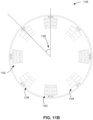
- FIG. 11B shows a cross sectioned view of the example cryogenic fuel tank 1100 of FIG. 11A .
- This cross sectioned view includes a first set of baffles 1102 and second set of baffles 1104.
- each baffle of the first set of baffles 1102 is placed at equal distances around the circumference of the inner surface of the cryogenic fuel tank 1100.
- each baffle of the second set of baffles 1104 is placed at equal distances around the circumference of the inner surface of the cryogenic fuel tank 1100.
- the first and second sets of baffles are angularly offset, so that in this cross-sectioned view, all baffles from the first set of baffles 1102 and all baffles from the second set of baffles 1104 are visible.
- the degree to which the second set of baffles 1102 is offset from the first set of baffles 1104 is referred to as an angle of stagger 1106.
- the angle of stagger 1106 is constant from baffle to baffle for the entire circumference, regardless of location along the length of the cryogenic fuel tank 1100.
- This example shows a four baffle per baffle set, resulting in a constant 45 degree angle of stagger 1106.
- the angle of stagger 1106 is greater than 45 degrees.
- the angle of stagger 1106 is less than 45 degrees. In still other examples, the angle of stagger 1106 varies, for example, where sets of baffles have different circumferential spacing than one another, different numbers of baffles, and/or unequal spacing.
- the baffle base (shown in FIG. 5B ) includes a torsion spring (shown in FIGS. 12A and 12B ) at the center of the baffle.
- the torsion spring at the center of the baffle base connects to the inner surface of the cryogenic fuel tank to allow the example baffle to rotate in the rotational direction (about the z-axis shown in FIG. 12B ).
- the torsion spring acts as a control to adapt to various fuel fill levels and acceleration profiles by enabling motion in the directions shown.
- One motion is a twisting motion.
- a twisting motion By utilizing a torsion spring, a twisting motion is enabled wherein the baffle may rotate in a rotational direction.
- the energy required to rotate the baffle comes from a kinetic energy of the fuel moving in the tank.
- the fuel has less kinetic energy to create slosh within the cryogenic fuel tank.
- a bending motion is also enabled from the use of a torsion spring.
- An example baffle with a torsion spring has the ability to have its members bend back and forth along the length of the tank or perpendicular to the length of the tank (along the x-axis or the y-axis as shown in FIG. 12B ). Similar to the twisting motion, the bending motion requires kinetic energy from the fuel to move. By consuming the kinetic energy of the fuel, the fuel has less kinetic energy to create slosh within the cryogenic fuel tank. Using the torsion spring to attach the baffle to the inner surface of the cryogenic fuel tank has the benefit of reducing cryogenic fuel slosh.
- FIG. 12A demonstrates a perspective view of an example cryogenic fuel tank 1200 with a plurality of baffles 1202.
- each baffle of the plurality of baffles 1202 is attached to the cryogenic fuel tank 1200 with a torsion spring 1210 at the base of the center of the baffle.
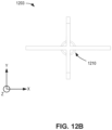
- FIG. 12B is a top view of an example baffle of the plurality of baffles 1202 from FIG. 12A .
- a torsion spring 1210 at the base of the center is shown.
- the torsion spring 1210 enables both bending (along the x-axis or the y-axis) and twisting (about the z-axis) motions.
- the spring 1210 allows the baffle 1202 to rotate or bend with motion of the fuel. Kinetic energy of the fuel is transferred to potential energy in the spring, dampening any potential fuel slosh.
- baffles depicted previously show a system of baffles having the same member arrangement and shape.
- a combination of different baffle member arrangements is used to dampen the cryogenic fuel slosh.
- FIG. 13 is a simplified top view illustration of a variety of baffle member arrangements similar to the baffle shown in isolation in FIG. 5A .
- each example baffle has at members on two different planes. Members positioned in two different planes can be used to form a cross wing baffle 1312, similar to the baffles shown in the plurality of baffles 804 in FIG. 8 .
- a baffle can be formed as a square baffle 1302, a circular baffle 1304, an inverted semicircular baffle 1306, a cross-cosine baffle 1308, a cross-sine baffle 1310, or a stepwise baffle 1314, 1316.
- FIG. 14 is an illustration of various example baffle side views. Similar to the baffle 500 shown in FIG. 5B , the baffles shown in FIG. 14 include fabrications to a height ratio of the range 0 ⁇ baffle height/tank radius ⁇ 0.5, to dampen potential fuel movement.
- the shape of the fabrication can be in various forms such as uniform 1402, conical 1404, concave 1406, and/or convex 1408.
- Baffles can be made from various methods of manufacture.
- a baffle could be made from additive manufacturing or could be fabricated via solidification expansion of an aluminum foam.
- FIG. 15 is an example baffle 1500 made in a honeycomb structure using an additive manufacturing process.
- the honeycomb structure 1500 of FIG. 15 can be affixed to the inner surface of the cryogenic fuel tank (e.g., the cryogenic fuel tank 700 of FIGS. 7-8 ).
- the example honeycomb structure 1500 uses the porosity described earlier to enable fluid flow through the honeycomb elements 1502. By enabling fluid flow through elements or passages 1502 of the honeycomb structure 1500, the fluid does not impact the baffle as much as the fluid would impact a solid structure. Relatively less fluid impact correlates to less fuel sloshing. Additionally, the hollow structure of the honeycomb is, by design, lightweight.
- example apparatuses and articles of manufacture have been disclosed that decrease weight and cost of baffle designs, remove compartmentalization of cryogenic fuel tanks and the associated need for fuel circulating pumps, and mitigate fuel slosh while allowing controlled mixing of fuel and vapors to reduce hydrogen stratification in cryogenic fuel tanks.
- a cryogenic fuel tank comprising an inner surface defining an interior of the cryogenic fuel tank to hold a fuel, and a plurality of baffles including a first baffle, the first baffle including a first member extending along a first plane, and a second member extending along a second plane, the first plane different from the second plane, the second member connected to the first member, the plurality of baffles connected to the inner surface.
- cryogenic fuel tank of any preceding clause wherein the inner surface is a curved inner surface.
- cryogenic fuel tank of any preceding clause wherein at least one of the first member or the second member is deformable.
- cryogenic fuel tank of any preceding clause wherein at least one of the first member or the second member includes a magnetorheological material.
- cryogenic fuel tank of any preceding clause wherein the magnetorheological material includes at least one of foamed aluminum, carbon fiber composites, glass fiber composites, or steel foam.
- cryogenic fuel tank of any preceding clause wherein the first baffle includes an opening in at least one of the first member or the second member.
- the plurality of baffles includes a second baffle, the second baffle including a third member extending along a third plane, and a fourth member extending along a fourth plane, the third plane different from the fourth plane, the fourth member connected to the third member.
- cryogenic fuel tank of any preceding clause wherein the first baffle is connected to the inner surface by a torsion spring to allow the first baffle to rotate in a rotational direction.
- cryogenic fuel tank of any preceding clause wherein the first baffle is connected to the inner surface by a torsion spring to allow the first baffle to bend.
- cryogenic fuel tank of any preceding clause wherein at least one of the first member or the second member has at least one of a uniform shape, a conical shape, concave shape, or a convex shape.
- cryogenic fuel tank of any preceding clause wherein at least one of the first member or the second member has a honeycomb structure.
- a system of baffles to dampen movement of a cryogenic fuel in a cryogenic fuel tank comprising a first baffle, the first baffle including a first surface to dampen fuel movement in at least a first direction, and a second baffle, the second baffle including a second surface to dampen fuel movement in at least a second direction, the second direction being different from the first direction, each baffle of the system of baffles being connected to the cryogenic fuel tank.
- baffles of any preceding clause wherein a base of the first baffle is curved to match a curved inner surface of the cryogenic fuel tank.
- baffles of any preceding clause wherein at least one of the first baffle or the second baffle deforms to dampen movement of the cryogenic fuel.
- baffles of any preceding clause wherein at least one surface of a baffle includes an opening to allow the cryogenic fuel to pass through.
- baffles of any preceding clause wherein a baffle is connected to the cryogenic fuel tank by a torsion spring to allow the baffle to rotate in a rotational direction.
- baffles of any preceding clause wherein a baffle is connected to the cryogenic fuel tank by a torsion spring to allow the baffle to rotate.
- each core of each baffle includes a magnetorheological material.
- the magnetorheological material includes at least one of foamed aluminum, carbon fiber composites, glass fiber composites, or steel foam.
- baffles of any preceding clause wherein at least one of the first baffle or the second baffle has at least one of a uniform shape, a conical shape, a concave shape, a convex shape, or a honeycomb shape.
- a means for dampening movement of a cryogenic fuel in a cryogenic fuel tank including a first surface to dampen fuel movement in at least a first direction, and a second surface to dampen fuel movement in at least a second direction, the second direction being different from the first direction, each means being connected to the cryogenic fuel tank.
- magnetorheological material includes at least one of foamed aluminum, carbon fiber composites, glass fiber composites, or steel foam.
- the means has at least one of a uniform shape, a conical shape, a concave shape, a convex shape, or a honeycomb shape.
- a method of manufacturing a baffle by additive manufacturing including a first surface to dampen fuel movement in at least a first direction, and second surface to dampen fuel movement in at least a second direction, the second direction being different from the first direction.
- a system of baffles comprising: a first baffle, the first baffle including: a first member to dampen fuel movement in at least a first direction; and a second member to dampen fuel movement in at least a second direction; and a second baffle, the second baffle including a third member to dampen fuel movement in at least a first direction, the second baffle being circumferentially offset and axially spaced from the first baffle.
- baffles of any preceding clause wherein a base of the first baffle is curved to match a curved inner surface of a fuel tank.
- baffles of any preceding clause wherein at least one of the first baffle or the second baffle is deformable to dampen movement of a fuel.
- baffles of any preceding clause wherein at least one member of a baffle includes an opening to allow a fuel to pass through.
- baffles of any preceding clause wherein a baffle is connected to a fuel tank by a torsion spring to allow the baffle to rotate in a rotational direction.
- baffles of any preceding clause wherein a baffle is connected to a fuel tank by a torsion spring to allow the baffle to bend.
- baffles of any preceding clause wherein a core of each baffle includes a magnetorheological material.
- the magnetorheological material includes at least one of foamed aluminum, carbon fiber composites, glass fiber composites, or steel foam.
- baffles of any preceding clause wherein at least one of the first baffle or the second baffle has at least one of a uniform shape, a conical shape, a concave shape, a convex shape.
- baffles of any preceding clause wherein the first baffle has a width to height ratio of 0.5 to 1.5.
- baffles of any preceding clause wherein the first baffle has a height constrained by the radius of a tank, where the baffle height divided by the tank radius is greater than zero and less than or equal to 0.5.
- baffles of any preceding clause wherein the first baffle is made via additive manufacturing into a honeycomb shape.
- baffles of any preceding clause wherein the first and second baffle are circumferentially offset by 45 degrees.
- baffles of any preceding clause wherein the first baffle is axially aligned with a second baffle, a third baffle, and a fourth baffle, each baffle circumferentially spaced apart from a respective adjacent baffle by 90 degrees.
- baffles of any preceding clause wherein the first baffle is axially aligned with a second baffle, a third baffle, a fourth baffle, a fifth baffle, and a sixth baffle, each baffle circumferentially spaced apart from a respective adjacent baffle by 60 degrees.
- baffles of any preceding clause wherein the first and second baffles represent first and second sets of baffles with circumferential spacing, the first and second sets of baffles axially spaced to allow for five sets of baffles.
- baffles of any preceding clause wherein the first member is at least one of straight, curved, sinusoidal, or cosine shaped.
- a cryogenic fuel tank including a system of baffles, the system of baffles comprising: a first baffle, the first baffle including: a first member to dampen fuel movement in at least a first direction; and a second member to dampen fuel movement in at least a second direction; and a second baffle, the second baffle including a third member to dampen fuel movement in at least a first direction, the second baffle being circumferentially offset and axially spaced from the first baffle.
Landscapes
- Engineering & Computer Science (AREA)
- Aviation & Aerospace Engineering (AREA)
- Mechanical Engineering (AREA)
- Chemical & Material Sciences (AREA)
- General Engineering & Computer Science (AREA)
- Combustion & Propulsion (AREA)
- Oil, Petroleum & Natural Gas (AREA)
- General Chemical & Material Sciences (AREA)
- Chemical Kinetics & Catalysis (AREA)
- Life Sciences & Earth Sciences (AREA)
- Sustainable Development (AREA)
- Sustainable Energy (AREA)
- Transportation (AREA)
- Physics & Mathematics (AREA)
- Fluid Mechanics (AREA)
- Filling Or Discharging Of Gas Storage Vessels (AREA)
Abstract
Description
- This invention was made with Government support under contract number 80NSSC19M0125 awarded by the National Aeronautics and Space Administration. The United States Government has certain rights in this invention.
- This disclosure relates generally to hydrogen aircraft fuel storage and, more particularly, to cryogenic hydrogen tank systems and methods for operating the same.
- In recent years, hydrogen aircraft have been developed that include multiple onboard cryogenic tanks to store liquid hydrogen fuel. As opposed to other tank fuels, liquid hydrogen is susceptible to boil off and bubble formation in the fuel when exposed to fuel slosh, or movement of the fuel in the cryogenic fuel tank. In aircraft, exposure to acceleration is of particular concern, as g-loads can cause the fuel to move in all degrees of freedom.
-
-
FIG. 1 is an illustration of an example first aircraft that can implement example integrated cryogenic hydrogen tank systems disclosed herein. -
FIG. 2 is an illustration of a cross-sectional view of the example first aircraft. -
FIG. 3A is an illustration of a front view of an example second aircraft that can implement the example cryogenic hydrogen tank systems disclosed herein. -
FIG. 3B is an illustration of a side view of the example second aircraft that can implement the example cryogenic hydrogen tank systems disclosed herein. -
FIG. 3C is an illustration of a top view of the example second aircraft that can implement the example cryogenic hydrogen tank systems disclosed herein. -
FIG. 4 is an illustration of an example aircraft that has example acceleration vectors. -
FIG. 5A is an illustration of an isometric view of an example isolated baffle. -
FIG. 5B is an illustration of a side view of the example isolated baffle. -
FIG. 5C is an illustration of a top view of the example isolated baffle. -
FIG. 6 is an isometric view of an example porous baffle. -
FIG. 7 is an illustration of an example cross-sectional top view of a fuel tank with a system of baffles. -
FIG. 8 is an illustration of an example cross-sectional isometric view of a fuel tank with a system of baffles. -
FIG. 9A is an illustration of a cross-sectional top view of a first arrangement of baffles. -
FIG. 9B is an illustration of a cross-sectional end view of the first arrangement of baffles. -
FIG. 10A is an illustration of a cross-sectional top view of a second arrangement of baffles. -
FIG. 10B is an illustration of a cross-sectional end view of the second arrangement of baffles. -
FIG. 11A is an illustration of a cross-sectional top view of a third arrangement of baffles with an angle of stagger. -
FIG. 11B is an illustration of a cross-sectional end view of the third arrangement of baffles with the angle of stagger. -
FIG. 12A is an illustration of a cross-sectional top view of an example fuel tank with a plurality of baffles and the motion of the baffles when the baffles are attached to the fuel tank by a torsion spring. -
FIG. 12B is an illustration of a top view of a baffle with a torsion spring. -
FIG. 13 is an illustration of a variety of different example baffle shapes. -
FIG. 14 is an illustration of example shapes in which example baffles can be formed. -
FIG. 15 is an illustration of an example baffle in a honeycomb structure. - In general, the same reference numbers will be used throughout the drawing(s) and accompanying written description to refer to the same or like parts. The figures are not to scale. Instead, the thickness of the layers or regions may be enlarged in the drawings. Although the figures show layers and regions with clean lines and boundaries, some or all of these lines and/or boundaries may be idealized. In reality, the boundaries and/or lines may be unobservable, blended, and/or irregular.
- As used herein, unless otherwise stated, the term "above" describes the relationship of two parts relative to Earth. A first part is above a second part, if the second part has at least one part between Earth and the first part. Likewise, as used herein, a first part is "below" a second part when the first part is closer to the Earth than the second part. As noted above, a first part can be above or below a second part with one or more of: other parts therebetween, without other parts therebetween, with the first and second parts touching, or without the first and second parts being in direct contact with one another.
- As used herein, stating that any part (e.g., a layer, film, area, region, or plate) is in any way on (e.g., positioned on, located on, disposed on, or formed on, etc.) another part, indicates that the referenced part is either in contact with the other part, or that the referenced part is above the other part with one or more intermediate part(s) located therebetween.
- As used herein, connection references (e.g., attached, coupled, connected, and joined) may include intermediate members between the elements referenced by the connection reference and/or relative movement between those elements unless otherwise indicated. As such, connection references do not necessarily infer that two elements are directly connected and/or in fixed relation to each other. As used herein, stating that any part is in "contact" with another part is defined to mean that there is no intermediate part between the two parts.
- Unless specifically stated otherwise, descriptors such as "first," "second," "third," etc., are used herein without imputing or otherwise indicating any meaning of priority, physical order, arrangement in a list, and/or ordering in any way, but are merely used as labels and/or arbitrary names to distinguish elements for ease of understanding the disclosed examples. In some examples, the descriptor "first" may be used to refer to an element in the detailed description, while the same element may be referred to in a claim with a different descriptor such as "second" or "third." In such instances, it should be understood that such descriptors are used merely for identifying those elements distinctly that might, for example, otherwise share a same name.
- "Including" and "comprising" (and all forms and tenses thereof) are used herein to be open ended terms. Thus, whenever a claim employs any form of "include" or "comprise" (e.g., comprises, includes, comprising, including, having, etc.) as a preamble or within a claim recitation of any kind, it is to be understood that additional elements, terms, etc., may be present without falling outside the scope of the corresponding claim or recitation. As used herein, when the phrase "at least" is used as the transition term in, for example, a preamble of a claim, it is open-ended in the same manner as the term "comprising" and "including" are open ended. The term "and/or" when used, for example, in a form such as A, B, and/or C refers to any combination or subset of A, B, C such as (1) A alone, (2) B alone, (3) C alone, (4) A with B, (5) A with C, (6) B with C, or (7) A with B and with C. As used herein in the context of describing structures, components, items, objects and/or things, the phrase "at least one of A and B" is intended to refer to implementations including any of (1) at least one A, (2) at least one B, or (3) at least one A and at least one B. Similarly, as used herein in the context of describing structures, components, items, objects and/or things, the phrase "at least one of A or B" is intended to refer to implementations including any of (1) at least one A, (2) at least one B, or (3) at least one A and at least one B. As used herein in the context of describing the performance or execution of processes, instructions, actions, activities and/or steps, the phrase "at least one of A and B" is intended to refer to implementations including any of (1) at least one A, (2) at least one B, or (3) at least one A and at least one B. Similarly, as used herein in the context of describing the performance or execution of processes, instructions, actions, activities and/or steps, the phrase "at least one of A or B" is intended to refer to implementations including any of (1) at least one A, (2) at least one B, or (3) at least one A and at least one B.
- As used herein, singular references (e.g., "a", "an", "first", "second", etc.) do not exclude a plurality. The term "a" or "an" object, as used herein, refers to one or more of that object. The terms "a" (or "an"), "one or more", and "at least one" are used interchangeably herein. Furthermore, although individually listed, a plurality of means, elements or method actions may be implemented by, e.g., the same entity or object. Additionally, although individual features may be included in different examples or claims, these may possibly be combined, and the inclusion in different examples or claims does not imply that a combination of features is not feasible and/or advantageous.
- As used herein, "approximately" and "about" modify their subjects/values to recognize the potential presence of variations that occur in real world applications. For example, "approximately" and "about" may modify dimensions that may not be exact due to manufacturing tolerances and/or other real world imperfections as will be understood by persons of ordinary skill in the art. For example, "approximately" and "about" may indicate such dimensions may be within a tolerance range of +/- 10% unless otherwise specified in the below description.
- In some examples used herein, the term "substantially" is used to describe a relationship between two parts that is within three degrees of the stated relationship (e.g., a substantially colinear relationship is within three degrees of being linear, a substantially perpendicular relationship is within three degrees of being perpendicular, a substantially parallel relationship is within three degrees of being parallel, etc.).
- In some examples herein, the term "substantially constant" is used to describe the state of a temperature, pressure, or some other property that is remaining within one unit of measure of the initial value (e.g. temperature is substantially constant in spite of a change from 11.1 degrees Celsius to 11.2 degrees Celsius).
- In some examples used herein, the term "substantially similar" or "substantially equal" is used to describe a relationship between two entities that indicate that they are the same within one unit of measurement of each other (e.g. a vapor pressure 374.0 kPa is substantially equal to a saturated pressure of 374.2 kPa.
- In some examples used herein, the term "substantially simultaneous" is used to describe a relationship between two components that are acting within one second of each other (e.g. at the same time).
- As used herein, the term "substantially completely" is used to describe a liquid phase of the hydrogen fuel and refers to a unit mass (e.g., one kilogram (kg), one pound (lb.), etc.) of LH2 that includes near 100% hydrogen in the liquid phase, such as at least 99%, such as at least 97.5%, such as at least 95%, such as at least 92.5%, such as at least 90%, such as at least 85%, or such as at least 75% of LH2 per unit mass. For example, one unit mass of LH2 substantially completely in the liquid phase can include 95% liquid hydrogen and 5% hydrogen vapor bubbles.
- As used herein, the phrase "in communication," including variations thereof, encompasses direct communication and/or indirect communication through one or more intermediary components, and does not require direct physical (e.g., wired) communication and/or constant communication, but rather additionally includes selective communication at periodic intervals, scheduled intervals, aperiodic intervals, and/or one-time events.
- Examples and teachings disclosed herein are summarized for purposes of reading the description below. Example cryogenic hydrogen tank systems are disclosed herein. Example cryogenic hydrogen tanks are used to transport liquid hydrogen (LH2) and/or hydrogen vapor (gaseous hydrogen (GH2)). In some examples, hydrogen aircraft consume the LH2 for propulsion, requiring the storage of large amounts of LH2 or GH2. Due to having six degrees of freedom of aircraft acceleration, the liquid hydrogen is susceptible to fluid movement inside a cryogenic hydrogen tank (hereinafter referred to as "sloshing") which can result in fuel boil off, bubble formation, and/or dynamic imbalance forces/moments on the aircraft transporting the liquid hydrogen.
- Hydrogen aircraft use hydrogen fuel (diatomic hydrogen) to eliminate carbon dioxide emissions relative to commercial aircraft that combust hydrocarbon fuels (e.g., Jet-A) for propulsion. However, hydrogen fuel poses a number of challenges as compared with combustible hydrocarbon liquid fuel. For example, in its gaseous form, hydrogen fuel has a much lower power density than Jet-A fuel. Even when hydrogen fuel is stored in the liquid phase, the volume of the liquid hydrogen (LH2) fuel is approximately four times the volume of Jet-A fuel to operate the aircraft over a given range. Moreover, hydrogen fuel has a relatively low boiling point and must be stored at cryogenic temperatures to be maintained in the liquid phase. A storage tank holding liquid hydrogen cryogenically requires more space overall and has an increased weight as compared with a storage tank holding a comparable volume of Jet-A fuel.
- Ordinary or normal hydrogen gas that is liquefied includes about 25 % Parahydrogen and 75 % Orthohydrogen. The liquid undergoes a slow natural conversion from the ortho to the para form, liberating heat. This exothermic reaction generates heat greater than the heat of vaporization. This temperature increase can cause the LH2 to boil, hence the term "boil-off," which is used herein to describe the warming and evaporation process of contained LH2. Boil-off losses occur at the rate of about 1 % per hour. A conversion catalyst minimizes or otherwise reduces these losses and yields better than 95 % parahydrogen during liquefaction. It is assumed that liquid parahydrogen will be used as a fuel and can be stored with only nominal losses. In other words, despite an insulation quality of the onboard LH2 tank, the temperature of the LH2 can rise, and the LH2 can boil-off. Hydrogen vapor bubbles formed from boil-off can enter extraction flowlines with LH2 fuel and flow downstream to an LH2 pump.
- When an example LH2 tank is refueled, the LH2 forms a first portion of the internal volume of the LH2 tank (e.g., 90%), and hydrogen vapor forms a second portion of the internal volume of the LH2 tank (e.g., 10%). As used herein, the "vapor pressure" refers to pressure acting on the interior walls of a tank (e.g., an onboard LH2 tank) and the surface of a liquid (e.g., LH2) within the tank. As used herein, "saturated pressure" refers to the vapor pressure when the LH2 and the hydrogen vapor are in equilibrium. That is, when the evaporation rate of the LH2 is equal to the condensation rate of the hydrogen vapor, the LH2 and the hydrogen vapor are in equilibrium and the vapor pressure is substantially similar to a saturated pressure at the given temperature. The saturated pressure is dependent on the temperature within the tank. Thus, when the temperature of the LH2 remains substantially constant, and when the LH2 settles after a given period (e.g., one hour, two hours, 12 hours, etc.), the LH2 and the hydrogen vapor are considered to be in equilibrium, and the vapor pressure is substantially similar to the saturated pressure.
- The saturated pressure can be determined based on the temperature within the tank. Thus, when the example onboard LH2 tank is isolated and is left to settle (e.g., without refueling or extracting hydrogen) for a given time (e.g., two hours, three hours, 12 hours, etc.) without heat addition, the temperature can remain substantially similar over time, the evaporation and condensation rates can equalize, and the vapor pressure can become substantially similar (e.g., equal) to the saturated pressure.
- Alternatively, when heat is added to the tank (e.g., via a thermosiphon loop, a heater, etc.), the evaporation rate of the LH2 increases and causes the vapor pressure to increase above the saturated pressure. In other words, when the temperature of the LH2 increases from a first temperature to a second temperature, the saturated pressure and the evaporation rate increase accordingly. However, the vapor pressure associated with the increased evaporation rate, for example eight to twelve bar of pressure, is greater than the saturated pressure associated with the second temperature. During operation, when the vapor pressure becomes substantially similar to the saturated pressure, there is not enough net positive pressure to drive the LH2 into extraction flowlines and cavitation can occur in the LH2. Thus, during operation, the vapor pressure is kept sufficiently higher, approximately two bar higher, than the saturated pressure. For example, the vapor pressure is maintained at levels that satisfy a safety threshold and an operational threshold of example tank systems disclosed herein. For example, 6 bar satisfies both thresholds of a tank system.
- Another consideration of cryogenic hydrogen tanks is sloshing. A 100% full cryogenic hydrogen tank will not experience sloshing. However, when there is room for dynamic liquid movement of the liquid hydrogen, sloshing may occur. To understand the effects of sloshing, a g-load, or load factor based on a relationship to the force of gravity, is placed on the large sized liquid tank and must be analyzed. G-loads are caused by acceleration of an example aircraft. The g-loads cause significant fluid motion to be of concern due to the large sized tank structure.
- Sloshing may have several effects on the tank due to liquid movement, as approximately one ton of liquid per tank is being sloshed or moved around. In some examples, sloshing imposes stress concentrations on a liquid hydrogen tank shell as well as on an outer vacuum chamber. In other examples, sloshing causes further liquid movement, which in turn mixes the liquid and vapor resulting in a temperature rise and corresponding tank pressure increase. This increase in tank temperature/pressure increases the amount of boil-off of liquid hydrogen and increases the amount of bubble formation. A greater amount of bubble formation increases the cavitation risk for the attached liquid hydrogen pump and puts further strain on a downstream phase separator when withdrawing liquid from the tank. In still other examples, sloshing creates an induced imbalance force or moment on the aircraft which may affect flight stability, lateral tanks, or other cryogenic hydrogen tanks. For these reasons, it is desired to minimize or otherwise reduce the amount of fuel slosh and hydrogen boil-off.
- In order to combat sloshing, a baffle can be used. Baffles, or structures placed within a fuel tank to reduce the fuel slosh within the fuel tank, have various designs such as ring baffles, vertical slotted baffles, horizontal porous baffles, or grid-like baffles. The challenge associated with creation of a baffle is reducing the weight in an aircraft, while increasing an the size and compliance of the baffle in reducing fuel slosh. Baffles can also be used to harness or control the reduced sloshing that can still occur in the fuel tank. Controlled sloshing provides a mixing effect that helps to reduce hydrogen stratification. Hydrogen stratification can be a concern for temperature and pressure build up, whereas sloshing tends to reduce the pressure in the tank due to the mixing of liquid and vapors.
- The refueling of an example LH2 tank presents another challenge. Current baffle designs, such as ring baffles, limit the methods to fill a fuel tank. Not only do these existing baffle designs take up more space and subsequently weigh more, but the existing baffle designs compartmentalize the example fuel tank. To completely fill a tank, pumps are required to be used to circulate the fuel and flow the fuel from compartment to compartment to ensure the LH2 tank is completely filled. This has an associated added cost, equipment, and effort, as well as added weight from the existing baffle design.
-
FIG. 1 is an illustration of an example first perspective view of an examplefirst aircraft 100 that can include example cryogenic hydrogen tank systems disclosed herein. Thefirst aircraft 100 includes aforward portion 102 and anaft portion 104 axially aligned along acenterline 106. Thefirst aircraft 100 includes afuselage 110,wings 120 attached to thefuselage 110, and anempennage 130. In the example ofFIG. 1 , thefirst aircraft 100 includes a pair ofwings 120, one on a port side of the first aircraft 100 (a port wing) and one on a starboard side of the first aircraft 100 (a starboard wing). - Although the
first aircraft 100 illustrated inFIG. 1 is a commercial airplane, examples described herein can also be applicable to other types of fixed-wing aircraft, such as cargo aircraft, unmanned aerial vehicles (UAV), etc. - The
fuselage 110 includes anose 112 and atail 114, and the centerline extends axially between thenose 112 and thetail 114. In the example ofFIG. 1 , thefirst aircraft 100 is substantially symmetric about thecenterline 106. Thefirst aircraft 100 can generate lift to perform flight operations when theaircraft 100 propels itself in aforward direction 115, wherein theforward direction 115 is generally aligned with thecenterline 106 and points from theaft portion 104 toward theforward portion 102 of theaircraft 100. - The
first aircraft 100 illustrated inFIGS. 1 is a commercial passenger aircraft including acockpit 116 to allow operation of thefirst aircraft 100. Thefirst aircraft 100 also includes apassenger compartment 118 to accommodate passenger seating. In the illustrated example, a first cryogenic hydrogen tank 160 ("first tank 160") is placed aft of thecockpit 116 to separate thecockpit 116 from thepassenger compartment 118, and a second cryogenic hydrogen tank 170 ("second tank 170") is placed aft of thepassenger compartment 118 to separate thepassenger compartment 118 from theempennage 130 and thetail 114. In some examples, thefirst aircraft 100 is a cargo aircraft including storage bays to replace and/or accompany thepassenger compartment 118. - The
first aircraft 100 also includes a propulsion system that produces a propulsive thrust required to propel thefirst aircraft 100 in flight, during taxiing operations, and the like. The propulsion system for thefirst aircraft 100 shown inFIG. 1 includesengines 140. In the example ofFIG. 1 , theengines 140 are attached to thewings 120 bypylons 122 in an under-wing configuration. Although theengines 140 are shown attached to thewings 120 in an under-wing configuration inFIG. 1 , in some other examples, theengines 140 can have alternative configurations and/or can be coupled to other portions of thefirst aircraft 100. For example, theengines 140 can additionally or alternatively include one or more engines (e.g., engines 140) coupled to other parts of thefirst aircraft 100, such as, for example, theempennage 130 and thefuselage 110. - The
wings 120 are attached to thefuselage 110 at example attachment points 124. As thefirst aircraft 100 is propelled through the air, thewings 120 generate lift and the resultant lift acts on thefirst aircraft 100 at a wing center of lift (described below), sometimes also referred to as a center of pressure. - The
engines 140 shown inFIG. 1 are hydrogen turbine engines that are each capable of selectively generating a propulsive thrust for thefirst aircraft 100. The amount of propulsive thrust can be controlled at least in part based on a volume of fuel provided to thehydrogen turbine engines 140 via a fuel system. In some examples, the LH2 fuel is stored in the firstcryogenic hydrogen tank 160 and the secondcryogenic hydrogen tank 170. Example tank systems disclosed herein include afuel delivery assembly 150 providing the fuel flow from thefirst tank 160 and/or thesecond tank 170 to theengines 140, and, more specifically, to a fuel manifold of the combustion section of the turbomachine of thehydrogen turbine engines 140. Thefuel delivery assembly 150 includes tubes, pipes, and the like, to fluidly connect the various components of example integrated tank systems to thehydrogen turbine engine 140. Thefuel delivery assembly 150 can also include various other components and systems used to distribute LH2 fuel in example tank systems to thegas turbine engines 140, such as pumps, vaporizers, and the like. - Example cryogenic hydrogen tank systems disclosed herein are described as including
first tank 160,second tank 170, and/or other cryogenic hydrogen tanks to provide LH2 fuel to be combusted in thehydrogen turbine engines 140. However, in some examples, cryogenic hydrogen tank systems disclosed herein can be used to supply LH2 and/or GH2 to other power systems, such as hydrogen fuel cells, power generators, and/or other electrical generators that rely on hydrogen fuel to function. - Example cryogenic hydrogen tank systems disclosed herein are configured to hold the hydrogen fuel at least partially within the liquid phase and are configured to provide hydrogen fuel to the
fuel delivery assembly 150 substantially completely in the liquid phase. However, due to refueling processes, in-flight sloshing, boil-off, etc., the LH2 can include vapor bubbles which can flow into LH2 extraction flowlines. Such vapor bubbles can cause cavitation damage to LH2 pumps driving flow from example integrated tank systems. Thus, example baffle systems are included in example cryogenic hydrogen tanks disclosed herein. Such baffle systems are described in greater detail below. - To store the hydrogen fuel substantially completely in the liquid phase, the hydrogen fuel is stored in cryogenic fuel tanks at cryogenic temperatures. For example, the first and
second tanks first aircraft 100 over a range of a typical continental flight, international flight, overseas flight, etc., can involve larger cryogenic hydrogen tank(s) (e.g.,first tank 160,second tank 170, etc.). -
FIG. 2 is a schematic illustration of a cross section of thefuselage 110 taken along line 2-2 inFIG. 1 . As mentioned above, thewings 120 are configured to generate a center oflift 202. In this example, the first and secondcryogenic hydrogen tanks fuselage 110. The first andsecond tanks fuselage 110 such that the first andsecond tanks lift 202. As noted above, thefirst aircraft 100 is symmetrical about thecenterline 106, and the wing center oflift 202 is located on thecenterline 106. Locating the first andsecond tanks lift 202 promotes the balance and stability of theaircraft 100 during flight. - More specifically, the
first tank 160 defines a first center ofgravity 204 and defines a moment arm MFT extending between the wing center oflift 202 and the first center ofgravity 204. Likewise, thesecond tank 170 defines a second center ofgravity 206 and defines a moment arm MAT extending between the wing center oflift 202 and the second center ofgravity 206. As shown inFIG. 2 , the first andsecond tanks gravity 208. In some examples, a position of the third center ofgravity 208 is based on a combination of the first center ofgravity 204 and the second center ofgravity 206. In the illustrated example, the third center ofgravity 208 is positioned aft of the wing center oflift 202. However, in some examples, the third center ofgravity 208 is aligned with the wing center oflift 202. - The
first tank 160 and thesecond tank 170 are positioned within thefuselage 110 such that the moment arms MFT, MAT are balanced when fuel levels therein are substantially similar (e.g. when both fuel tanks are half filled). When the first andsecond tanks fuel delivery assemblies 150 are to extract LH2 from the first andsecond tanks aircraft 100. Such synchronization can lead to complex control systems of thefuel delivery assemblies 150. Furthermore, when separated, the first andsecond tanks second tanks second tanks fuel delivery assemblies 150. -
FIG. 3A is an illustration of a front view of an examplesecond aircraft 300 that can include example cryogenic hydrogen tanks disclosed herein. In this example,front view 306 shows thesecond aircraft 300 includes a first group ofengines 308a and a second group ofengines 308b. In some examples, thesecond aircraft 300 includes a fuel delivery system to provide LH2 fuel from example tank systems to the first and second groups ofengines engines second aircraft 300 in flight, during taxiing operations, and the like. In the example ofFIG. 3A , each engine of the first and second groups ofengines FIG. 3C ) via a pylon or some other connective structure not shown inFIGs. 3A-3C . Although the first and second groups ofengines FIG. 3C ) inFIG. 3A , in other examples, one or more of the engines of the first and/or second groups ofengines second aircraft 300. - Similar to the example
first aircraft 100 ofFIG. 1 , the first and second groups ofengines FIG. 3A are hydrogen turbine engines that are each able to selectively generate a propulsive thrust for thesecond aircraft 300. The amount of propulsive thrust can be controlled at least in part based on a volume of liquid hydrogen (LH2) fuel provided to the first and second groups ofengines FIGs. 3A-3C , the fuel delivery system included in thesecond aircraft 300 can include elements (e.g., the fuel delivery assembly 150) that are substantially similar to those illustrated inFIGS. 1 and/or 2. -
FIG. 3B is an illustration of the same examplesecond aircraft 300 from a side view. In this example,side view 304 shows the aircraft that can include example cryogenic hydrogen tanks disclosed herein. Although thesecond aircraft 300 shown inFIG. 3B is a commercial passenger aircraft, examples described herein can also be applicable to other fixed-wing aircraft, including cargo aircraft, unmanned aerial vehicles (UAV), hypersonic launch vehicles, etc. -
FIG. 3C is an illustration of a top view of the examplesecond aircraft 300 that can include example cryogenic hydrogen tanks disclosed herein. The example top-down view 302 is intended to show placements and/or locations of various elements of thesecond aircraft 300 relative to such a view but not intended to illustrate a cross-sectional view of thesecond aircraft 300. Thesecond aircraft 300 illustrated inFIG. 3C is substantially symmetric about acenterline 310 and includes afuselage 312 and anempennage 314. Theexample centerline 310 extends from anose 316 to atail 318 of thesecond aircraft 300. - Similar to the example first aircraft 100 (
FIGS. 1 and2 ), thesecond aircraft 300 includeswings 320 attached to thefuselage 312, wherein one wing is positioned on a port side of the second aircraft 300 (a port wing), and another wing is positioned on a starboard side of the second aircraft 300 (a starboard wing). As thesecond aircraft 300 is propelled through the air, thewings 320 generate lift and the resultant lift acts on thesecond aircraft 300 at a wing center oflift 321, sometimes also referred to as a center of pressure. The examplesecond aircraft 300 also includesstabilizers 322 attached to theempennage 314, wherein one stabilizer is positioned on the port side of the second aircraft 300 (a port stabilizer), and another stabilizer is positioned on the starboard side of the second aircraft 300 (a starboard stabilizer). As illustrated inFIG. 3 , a forward direction (toward the nose 316), an aft direction (toward the tail 318), a port direction (toward the left side ofFIG. 3 ), and a starboard direction (toward the right side ofFIG. 3 ) are associated with thesecond aircraft 300. - Example cryogenic hydrogen tank systems disclosed herein can store LH2 fuel in a first group of cryogenic hydrogen tanks 324 ("first group of
tanks 324") and a second group of cryogenic hydrogen tanks 326 ("second group oftanks 326"). The first group oftanks 324 includes afirst tank 324a, asecond tank 324b, and athird tank 324c. The second group oftanks 326 includes afourth tank 326a, afifth tank 326b, and asixth tank 326c. In some examples, thetanks 324a-324c, 326a-326c are substantially similar to the first andsecond tanks FIGS. 1 and2 . - In the illustrated example of
FIG. 3C , the first and second groups oftanks fuselage 312. The first andfourth tanks fifth tanks sixth tanks fifth tanks FIG. 3C , each of thefirst tank 324a defines a first center ofgravity 328a, thesecond tank 324b defines a second center ofgravity 328b, thethird tank 324c defines a third center ofgravity 328c, thefourth tank 326a defines a fourth center ofgravity 330a, thefifth tank 326b defines a fifth center ofgravity 330b, and thesixth tank 326c defines a sixth center ofgravity 330c. In some examples, the second center ofgravity 328b, the fifth center ofgravity 330b, and the wing center oflift 321 are substantially aligned along areference line 332 oriented transverse (or substantially perpendicular) to thecenterline 310. - In some examples, the first and second groups of
tanks fuselage 312 such that, relative to the forward and aft directions, the first, third, fourth, and sixth centers ofgravity lift 321. Similarly, relative to the port and starboard directions, the first, third, fourth, and sixth centers ofgravity centerline 310. - An example forward tank moment arm, MFT, extends from the wing center of
lift 321 to the centers of gravity of the two forward tanks, and an example aft tank moment arm, MAT, extends from the wing center oflift 321 to the centers of gravity of the two aft tanks. When the first and second groups oftanks - As shown in
FIG. 3 , the first and second groups oftanks gravity 334. In some examples, a position of the seventh center ofgravity 334 is based on a combination of the first, second, third, fourth, fifth, and sixth centers of gravity 228a-228c, 230a-230c. In the illustrated example, the seventh center ofgravity 334 is positioned aft of the wing center oflift 321. However, in some examples, the seventh center ofgravity 334 is aligned with the wing center oflift 321. - The
second aircraft 300 illustrated inFIGs. 3A-3C is a commercial passenger aircraft similar to the first aircraft shown inFIG. 1 . However, since the first and second groups oftanks second aircraft 300 has a longer range than the first aircraft 100 (FIGS. 1 and2 ). As mentioned previously, to increase the LH2 fuel capacity and range of hydrogen aircraft, more cryogenic tanks are included rather than developing one larger onboard tank. Having multiple cryogenic tanks distributes fuel weight more evenly throughout thefuselage 312 than a single tank. - For example, during takeoff, the
second aircraft 300 can pitch up to an angle of attack (e.g., 10 degrees, 15 degrees, etc.). If thesecond aircraft 300 included one onboard tank to carry the same fuel capacity as six individual tanks, the majority of the LH2 would transfer behind the wing center oflift 321 during takeoff, move a center of gravity of the one onboard tank in the aft direction, and impart some undesirable instability to thesecond aircraft 300. However, because thesecond aircraft 300 includes six tanks, the respective centers ofgravity 328a-328c, 330a-330c would not shift as significantly in the aft direction during takeoff relative to the example singular onboard tank, thus allowing thesecond aircraft 300 to maintain controllability and stability during most stages of flight (e.g., takeoff, cruise, landing, etc.). - Some disadvantages and/or challenges arise in hydrogen aircraft (e.g., the first and/or second hydrogen aircraft 100 (
FIGS. 1 and2 ), 300 (FIGS. 3A-3C )) with multiple (e.g., two, three, six, etc.) separate cryogenic hydrogen tanks. For example, during a refueling process, individual tanks are filled separately and sequentially via inlet ports on each tank. The refueling process for multiple individual tanks includes connecting a refueling flowline to a first tank, filling the first tank to capacity with LH2, disconnecting the refueling flowline, purging the refueling flowline, connecting the refueling flowline to a second tank in the group of tanks (e.g., the first group oftanks 324a), and repeating the refueling process until each of the individual tanks is filled to capacity. - Aircraft and cryogenic fuel tanks onboard can be subject to acceleration in any of six degrees of freedom: up/down, left/right, forward/backward, roll, pitch, and yaw. For example,
FIG. 4 is an illustration of an isometric view of an examplethird aircraft 400. This example aircraft is shown to be accelerating forwards and upward at an angle of fifteen degrees, as an aircraft would during takeoff, as demonstrated byacceleration vectors resultant example vector 406, shows the longitudinal loading force exerted on the aircraft and its contents, including a cryogenic hydrogen tank (not shown). An example load of 0.245g applied across theforward acceleration vector 402 coupled with an example load of 0.065g applied by theupward acceleration vector 404 results in 0.250g of acceleration at the fifteen degree angle. In an example thirty percent full cryogenic LH2 fuel tank with a length of 3327.4 mm and a nominal inner radius of 839.3 mm, applying the example load for one second results in the magnitude of slosh exceeding 2.500 meters per second after 3 seconds. This can result in boil-off of the LH2 or an imbalance force and moment on the aircraft. - To mitigate fuel slosh that results in boil-off of LH2 or substantial imbalance forces and moments on aircraft, baffles are used.
FIG. 5A presents an isometric view of anexample baffle 500 that can be used in conjunction with a cryogenic fuel tank (shown later inFIG. 8 ) to mitigate cryogenic fuel slosh. Theexample baffle 500 has abaffle core 502. In some examples, thebaffle core 502 is hollow, whereas thebaffle core 502 is solid in other examples. - Material used to construct the
baffle core 502 includes magnetorheological materials such as foamed aluminum, carbon fiber composites, glass fiber composites, steel foam, a combination of materials, and/or other composite structures. These magnetorheological materials give the baffle a variable stiffness such that two baffles constructed of the same material may have two different stiffnesses. Additionally, the magnetorheological materials give the baffle the property that the stiffness within each baffle varies. In some examples, thebaffle 500 is constructed of materials with compliance to allow the baffle structure to deform to reduce the slosh of cryogenic fuel. -
FIG. 5B shows a side view of theexample baffle 500 in isolation. In the example ofFIG. 5B , thebaffle 500 is angular, meaning thebaffle 500 has a base 508 that is curved to match a curved inner surface of the cryogenic fuel tank, shown later inFIG. 8 . This angular feature helps prevent fuel from passing under the baffle and dampens potential fuel slosh by an imposition of the example baffle in a fluid path though the cryogenic fuel tank. - A height of an example baffle is greater than a minimum height to ensure that fuel does not simply pass over the top of the baffle without the baffle imposing a structure to dampen movement of the fuel. A height of the baffle that is less than a maximum height minimizes or otherwise reduces the weight of the baffle, is more efficient in terms of fueling by ensuring that there is no need to compartmentalize the tank or use pumps to circulate the fuel, and does not induce additional sloshing of the liquid hydrogen fuel. In the example of
FIG. 5B , thebaffle 500 is of an example height perpendicular to thebaffle base 508 within range of a baffle height to tank radius ratio, where 0 < baffle height/tank radius ≤ 0.5. - A size of the
example baffle 500 helps determine its effectiveness in mitigating cryogenic fuel slosh. A width of thebaffle 500 is measured along the axis of thebaffle base 508 and is constrained by a height of thebaffle 500, presenting a baffle width to baffle height ratio. Having a minimum width ensures imposition of thebaffle 500 in any potential fluid path, mitigating fuel slosh. By having a range on the baffle width/baffle height ratio, thebaffle 500 is constrained to allow space between the baffles and not compartmentalize the example cryogenic fuel tank. In the example ofFIG. 5B , a baffle width to baffle height ratio of thebaffle 500 is in the range of 0.5 ≤ baffle width/baffle height ≤ 1.5. -
FIG. 5C showsexample baffle 500 from a top view.Baffle 500 has afirst member 504 extending along afirst plane 510 in a first direction, and asecond member 506 extending along asecond plane 512 in a second direction. In this example, thebaffle 500 has thefirst member 504 extending along thefirst plane 510 perpendicular to thesecond member 506 extending along thesecond plane 512. Not all baffles include the members as perpendicular or straight. Some example baffle planes are curved, cosine, or are sinusoidal, as shown later inFIG. 13 . - Baffle members can be non-porous or unslotted to prevent the passage of fluid through the baffle. As an alternative, the baffle members can be porous to allow the passage of fluid through holes or slots and mitigate fluid impacting the surface of the baffle. Usage of a non-porous or unslotted baffle dampens potential fuel slosh by an imposition of the example baffle in a fluid path though the cryogenic fuel tank. An advantage to utilizing a porous baffle is a reduction in surface area impacted when fuel is subject to acceleration. By reducing the surface area through the introduction of pores, such as holes or slots, less fuel impacts the baffle and, therefore, less fluid splashing occurs. Less fuel splashing dampens the fuel motion. Another advantage of having a porous baffle includes weight reduction of the baffle.
- While
FIG. 5B shows an examplenon-porous baffle 500,FIG. 6 shows an exampleporous baffle 600. In this example, the baffle members are slotted or porous to allow fuel to pass through. Example holes 602 enable fluid motion, reducing the amount of fuel impacting thesurfaces 604 ofmembers baffle 600 and resulting splash. The fuel slosh is dampened, as there is less fluid splashing within an example cryogenic fuel tank. -
FIG. 7 shows a top view of an examplecryogenic fuel tank 700. In this example, anexample baffle base 508 is connected to an inner surface of acryogenic fuel tank 702. In this example, thebaffle base 508 is connected to the cryogenic fuel tankinner surface 702 by welding. In other examples, epoxy-based adhesives may be used to attach a baffle to a cryogenic fuel tank inner surface. Connecting thebaffle base 508 to the inner surface of the cryogenic fuel tank via welding or epoxy-based adhesive gives rigidity to the structure and ensures potential fuel slosh is dampened by an imposition of the example baffle in a fluid path though the cryogenic fuel tank. -
FIG. 8 illustrates an isometric view of the examplecryogenic fuel tank 700 to hold a cryogenic fuel, such as liquid hydrogen. In this example, thecryogenic fuel tank 700 has a system ofbaffles 804 connected to itsinner surface 702 to mitigate cryogenic fuel slosh. The plurality ofbaffles 804 works to dampen the fuel slosh in multiple directions by havingmembers baffles 804 is connected to theinner surface 702 of thecryogenic fuel tank 700. - Dampening cryogenic fuel slosh is dependent on many factors such as the location of the baffles along the length of the cryogenic fuel tank, the location of the baffles around the circumference of the cryogenic fuel tank (also referred to as the angle of stagger), the number of baffles along the length of the cryogenic fuel tank, and the number of baffles along the circumference of the fuel tank. The example system of
baffles 804 is constrained based on a ratio of a size of each baffle, circumferential spacing between baffles within a set, and axial spacing between sets of baffles. The three constraints yield a density of baffles within an example cryogenic fuel tank. -
FIG. 9A shows an example top view of a system of baffles 904 circumferentially spaced around theinner surface 902 of acryogenic fuel tank 900. A set of four circumferentially spaced baffles at six axial positions is shown. To highlight the number of baffles 904 at a location along the length of thecryogenic fuel tank 900, a portion ofcryogenic fuel tank 900 is shown to be cross sectioned and later depicted inFIG. 9B . - The example baffles of
FIG. 9A highlight an alternating spatial configuration showing first set ofbaffles 906 and third set of baffles 910 along the length of thecryogenic fuel tank 900 being aligned in the axial direction. A second set ofbaffles 908 and fourth set of baffles 912 along the length of thecryogenic fuel tank 900 are shown as being aligned in the axial direction. In this example, there is an angle of stagger between the first set of baffles 906and the second set ofbaffles 908. In this example, the third set of baffles 910 is eclipsed by the first set ofbaffles 906, and the fourth set of baffles 912 is eclipsed by the second set ofbaffles 908. -
FIG. 9B shows a cross-sectioned view 9B ofcryogenic fuel tank 900 ofFIG 9A . As shown inFIG. 9B , theinner surface 902 of thecryogenic fuel tank 900 has a set of fourbaffles 908. The set of fourbaffles 908 are spaced out along the circumference of the cryogenic tankinner surface 902 equidistant. As shown byangle 914, each baffle is separated circumferentially by 90 degrees in this configuration. -
FIG. 10A shows an alternate example in which acryogenic fuel tank 1000 has a system ofbaffles 1004 that are placed closer together as compared toFIG. 9A. FIG. 9A highlights an angle of 90 degrees between baffles, whereasFIG 10A shows an arrangement of baffles having an angle of 60 degrees. In this example, there are six baffles arranged circumferentially around aninner surface 1002 of acryogenic fuel tank 1000 at five different axial positions along the longitudinal axis along the length of the examplecryogenic fuel tank 1000. A portion ofcryogenic fuel tank 1000 is shown to be cross sectioned and later depicted inFIG. 10B . In yet other examples, the size of the baffles is smaller, but the number of baffles is increased. -
FIG. 10B shows across-sectioned view 10B ofcryogenic fuel tank 1000 ofFIG 10A . As shown inFIG. 10B , theinner surface 1002 of thecryogenic fuel tank 1000 has sixbaffles 1006 attached at any given location along the length of thecryogenic fuel tank 1000. Thebaffles 1006 are spaced out along the circumference of the cryogenic tankinner surface 1002 equidistant. As shown byangle 1014, each baffle is separated circumferentially by 60 degrees in this configuration. - There are many different configurations for baffle placement inside of a cryogenic fuel tank. Additional configurations may include different patterns or randomization. The example patterns for baffle placement are not exclusive.
-
FIG. 11A highlights an angle of stagger between a first set ofbaffles 1102 and an adjacent second set ofbaffles 1104. Across-sectional view 11B is taken from a first location 1101 along the length of an examplecryogenic fuel tank 1100. The first set ofbaffles 1102 is spaced circumferentially around the circumference of thecryogenic fuel tank 1100 at the first location 1101. A second set ofbaffles 1104 is spaced circumferentially around the circumference of thecryogenic fuel tank 1100 at a second location 1103 along the length of the examplecryogenic fuel tank 1100. The second set ofbaffles 1104 is offset circumferentially, or staggered, with respect to the first set ofbaffles 1102. As such, the second set ofbaffles 1104 do not to align with the first set ofbaffles 1102 in the axial direction as shown inFIG. 11A . -
FIG. 11B shows a cross sectioned view of the examplecryogenic fuel tank 1100 ofFIG. 11A . This cross sectioned view includes a first set ofbaffles 1102 and second set ofbaffles 1104. In this example, each baffle of the first set ofbaffles 1102 is placed at equal distances around the circumference of the inner surface of thecryogenic fuel tank 1100. Additionally, each baffle of the second set ofbaffles 1104 is placed at equal distances around the circumference of the inner surface of thecryogenic fuel tank 1100. - The first and second sets of baffles are angularly offset, so that in this cross-sectioned view, all baffles from the first set of
baffles 1102 and all baffles from the second set ofbaffles 1104 are visible. The degree to which the second set ofbaffles 1102 is offset from the first set ofbaffles 1104 is referred to as an angle of stagger 1106. In this example, the angle of stagger 1106 is constant from baffle to baffle for the entire circumference, regardless of location along the length of thecryogenic fuel tank 1100. This example shows a four baffle per baffle set, resulting in a constant 45 degree angle of stagger 1106. In some examples, the angle of stagger 1106 is greater than 45 degrees. In other examples, the angle of stagger 1106 is less than 45 degrees. In still other examples, the angle of stagger 1106 varies, for example, where sets of baffles have different circumferential spacing than one another, different numbers of baffles, and/or unequal spacing. - In some examples, the baffle base (shown in
FIG. 5B ) includes a torsion spring (shown inFIGS. 12A and12B ) at the center of the baffle. The torsion spring at the center of the baffle base connects to the inner surface of the cryogenic fuel tank to allow the example baffle to rotate in the rotational direction (about the z-axis shown inFIG. 12B ). The torsion spring acts as a control to adapt to various fuel fill levels and acceleration profiles by enabling motion in the directions shown. - One motion is a twisting motion. By utilizing a torsion spring, a twisting motion is enabled wherein the baffle may rotate in a rotational direction. The energy required to rotate the baffle comes from a kinetic energy of the fuel moving in the tank. By consuming the kinetic energy of the fuel, the fuel has less kinetic energy to create slosh within the cryogenic fuel tank.
- A bending motion is also enabled from the use of a torsion spring. An example baffle with a torsion spring has the ability to have its members bend back and forth along the length of the tank or perpendicular to the length of the tank (along the x-axis or the y-axis as shown in
FIG. 12B ). Similar to the twisting motion, the bending motion requires kinetic energy from the fuel to move. By consuming the kinetic energy of the fuel, the fuel has less kinetic energy to create slosh within the cryogenic fuel tank. Using the torsion spring to attach the baffle to the inner surface of the cryogenic fuel tank has the benefit of reducing cryogenic fuel slosh. - In the example shown in
FIG. 7 , the baffles shown are fixed in place to dampen fuel slosh. In contrast,FIG. 12A demonstrates a perspective view of an examplecryogenic fuel tank 1200 with a plurality ofbaffles 1202. In this example, each baffle of the plurality ofbaffles 1202 is attached to thecryogenic fuel tank 1200 with atorsion spring 1210 at the base of the center of the baffle. By allowing each baffle of the example plurality ofbaffles 1202 to rotate with atwisting motion 1204 and bend with abending motion 1206, the potential fuel slosh is further dampened by requiring energy from the moving fuel to twist or bend the plurality ofbaffles 1202. -
FIG. 12B is a top view of an example baffle of the plurality ofbaffles 1202 fromFIG. 12A . Atorsion spring 1210 at the base of the center is shown. As depicted inFIG. 12A , thetorsion spring 1210 enables both bending (along the x-axis or the y-axis) and twisting (about the z-axis) motions. Thespring 1210 allows thebaffle 1202 to rotate or bend with motion of the fuel. Kinetic energy of the fuel is transferred to potential energy in the spring, dampening any potential fuel slosh. - The example baffles depicted previously show a system of baffles having the same member arrangement and shape. In alternate examples, a combination of different baffle member arrangements is used to dampen the cryogenic fuel slosh.
-
FIG. 13 is a simplified top view illustration of a variety of baffle member arrangements similar to the baffle shown in isolation inFIG. 5A . From the example inFIG. 5C , each example baffle has at members on two different planes. Members positioned in two different planes can be used to form across wing baffle 1312, similar to the baffles shown in the plurality ofbaffles 804 inFIG. 8 . Additionally, a baffle can be formed as asquare baffle 1302, acircular baffle 1304, an invertedsemicircular baffle 1306, across-cosine baffle 1308, across-sine baffle 1310, or astepwise baffle -
FIG. 14 is an illustration of various example baffle side views. Similar to thebaffle 500 shown inFIG. 5B , the baffles shown inFIG. 14 include fabrications to a height ratio of therange 0 < baffle height/tank radius ≤ 0.5, to dampen potential fuel movement. The shape of the fabrication can be in various forms such as uniform 1402, conical 1404, concave 1406, and/or convex 1408. - Baffles can be made from various methods of manufacture. For example, a baffle could be made from additive manufacturing or could be fabricated via solidification expansion of an aluminum foam.
-
FIG. 15 is anexample baffle 1500 made in a honeycomb structure using an additive manufacturing process. Thehoneycomb structure 1500 ofFIG. 15 can be affixed to the inner surface of the cryogenic fuel tank (e.g., thecryogenic fuel tank 700 ofFIGS. 7-8 ). Theexample honeycomb structure 1500 uses the porosity described earlier to enable fluid flow through thehoneycomb elements 1502. By enabling fluid flow through elements orpassages 1502 of thehoneycomb structure 1500, the fluid does not impact the baffle as much as the fluid would impact a solid structure. Relatively less fluid impact correlates to less fuel sloshing. Additionally, the hollow structure of the honeycomb is, by design, lightweight. - From the foregoing, it will be appreciated that example apparatuses and articles of manufacture have been disclosed that decrease weight and cost of baffle designs, remove compartmentalization of cryogenic fuel tanks and the associated need for fuel circulating pumps, and mitigate fuel slosh while allowing controlled mixing of fuel and vapors to reduce hydrogen stratification in cryogenic fuel tanks.
- Example methods, apparatus, systems, and articles of manufacture to cryogenic fuel dampening baffles are disclosed herein. Further aspects of the disclosure are provided by the subject matter of the following clauses:
- A cryogenic fuel tank comprising an inner surface defining an interior of the cryogenic fuel tank to hold a fuel, and a plurality of baffles including a first baffle, the first baffle including a first member extending along a first plane, and a second member extending along a second plane, the first plane different from the second plane, the second member connected to the first member, the plurality of baffles connected to the inner surface.
- The cryogenic fuel tank of any preceding clause, wherein the inner surface is a curved inner surface.
- The cryogenic fuel tank of any preceding clause, wherein at least one of the first member or the second member is deformable.
- The cryogenic fuel tank of any preceding clause, wherein at least one of the first member or the second member includes a magnetorheological material.
- The cryogenic fuel tank of any preceding clause, wherein the magnetorheological material includes at least one of foamed aluminum, carbon fiber composites, glass fiber composites, or steel foam.
- The cryogenic fuel tank of any preceding clause, wherein the first baffle includes an opening in at least one of the first member or the second member.
- The cryogenic fuel tank of any preceding clause, wherein the plurality of baffles includes a second baffle, the second baffle including a third member extending along a third plane, and a fourth member extending along a fourth plane, the third plane different from the fourth plane, the fourth member connected to the third member.
- The cryogenic fuel tank of any preceding clause, wherein the first baffle is connected to the inner surface by a torsion spring to allow the first baffle to rotate in a rotational direction.
- The cryogenic fuel tank of any preceding clause, wherein the first baffle is connected to the inner surface by a torsion spring to allow the first baffle to bend.
- The cryogenic fuel tank of any preceding clause, wherein at least one of the first member or the second member has at least one of a uniform shape, a conical shape, concave shape, or a convex shape.
- The cryogenic fuel tank of any preceding clause, wherein at least one of the first member or the second member has a honeycomb structure.
- A system of baffles to dampen movement of a cryogenic fuel in a cryogenic fuel tank, the system of baffles comprising a first baffle, the first baffle including a first surface to dampen fuel movement in at least a first direction, and a second baffle, the second baffle including a second surface to dampen fuel movement in at least a second direction, the second direction being different from the first direction, each baffle of the system of baffles being connected to the cryogenic fuel tank.
- The system of baffles of any preceding clause, wherein a base of the first baffle is curved to match a curved inner surface of the cryogenic fuel tank.
- The system of baffles of any preceding clause, wherein at least one of the first baffle or the second baffle deforms to dampen movement of the cryogenic fuel.
- The system of baffles of any preceding clause, wherein at least one surface of a baffle includes an opening to allow the cryogenic fuel to pass through.
- The system of baffles of any preceding clause, wherein a baffle is connected to the cryogenic fuel tank by a torsion spring to allow the baffle to rotate in a rotational direction.
- The system of baffles of any preceding clause, wherein a baffle is connected to the cryogenic fuel tank by a torsion spring to allow the baffle to rotate.
- The system of baffles of any preceding clause, wherein each core of each baffle includes a magnetorheological material.
- The system of baffles of any preceding clause, wherein the magnetorheological material includes at least one of foamed aluminum, carbon fiber composites, glass fiber composites, or steel foam.
- The system of baffles of any preceding clause, wherein at least one of the first baffle or the second baffle has at least one of a uniform shape, a conical shape, a concave shape, a convex shape, or a honeycomb shape.
- A means for dampening movement of a cryogenic fuel in a cryogenic fuel tank, the means including a first surface to dampen fuel movement in at least a first direction, and a second surface to dampen fuel movement in at least a second direction, the second direction being different from the first direction, each means being connected to the cryogenic fuel tank.
- The means for dampening movement of any preceding clause, wherein a base of the means matches a curved inner surface of the cryogenic fuel tank.
- The means for dampening movement of any preceding clause, wherein a surface of the means deforms to dampen movement of the cryogenic fuel.
- The means for dampening movement of any preceding clause, wherein at least one surface the means includes an opening to allow the cryogenic fuel to pass through.
- The means for dampening movement of any preceding clause, wherein a means is connected to the cryogenic fuel tank by a torsion spring to allow the baffle to rotate in a rotational direction.
- The means for dampening movement of any preceding clause, wherein the means is connected by a torsion spring to allow the baffle to bend.
- The means for dampening movement of any preceding clause, wherein the means includes a magnetorheological material.
- The means for dampening movement of any preceding clause, wherein the magnetorheological material includes at least one of foamed aluminum, carbon fiber composites, glass fiber composites, or steel foam.
- The means for dampening movement of any preceding clause, wherein the means has at least one of a uniform shape, a conical shape, a concave shape, a convex shape, or a honeycomb shape.
- A method of manufacturing a baffle by additive manufacturing, the baffle including a first surface to dampen fuel movement in at least a first direction, and second surface to dampen fuel movement in at least a second direction, the second direction being different from the first direction.
- The following claims are hereby incorporated into this detailed Description by this reference. Although certain example systems, methods, apparatus, and articles of manufacture have been disclosed herein, the scope of coverage of this patent is not limited thereto. On the contrary, this patent covers all systems, methods, apparatus, and articles of manufacture fairly falling within the scope of the claims of this patent.
- A system of baffles comprising: a first baffle, the first baffle including: a first member to dampen fuel movement in at least a first direction; and a second member to dampen fuel movement in at least a second direction; and a second baffle, the second baffle including a third member to dampen fuel movement in at least a first direction, the second baffle being circumferentially offset and axially spaced from the first baffle.
- The system of baffles of any preceding clause, wherein a base of the first baffle is curved to match a curved inner surface of a fuel tank.
- The system of baffles of any preceding clause, wherein at least one of the first baffle or the second baffle is deformable to dampen movement of a fuel.
- The system of baffles of any preceding clause, wherein at least one member of a baffle includes an opening to allow a fuel to pass through.
- The system of baffles of any preceding clause, wherein a baffle is connected to a fuel tank by a torsion spring to allow the baffle to rotate in a rotational direction.
- The system of baffles of any preceding clause, wherein a baffle is connected to a fuel tank by a torsion spring to allow the baffle to bend.
- The system of baffles of any preceding clause, wherein a core of each baffle includes a magnetorheological material.
- The system of baffles of any preceding clause, wherein the magnetorheological material includes at least one of foamed aluminum, carbon fiber composites, glass fiber composites, or steel foam.
- The system of baffles of any preceding clause, wherein at least one of the first baffle or the second baffle has at least one of a uniform shape, a conical shape, a concave shape, a convex shape.
- The system of baffles of any preceding clause, wherein the first baffle has a width to height ratio of 0.5 to 1.5.
- The system of baffles of any preceding clause, wherein the first baffle has a height constrained by the radius of a tank, where the baffle height divided by the tank radius is greater than zero and less than or equal to 0.5.
- The system of baffles of any preceding clause, wherein the first baffle is made via additive manufacturing into a honeycomb shape.
- The system of baffles of any preceding clause, wherein the first and second baffle are circumferentially offset by 45 degrees.
- The system of baffles of any preceding clause, wherein the first baffle is axially aligned with a second baffle, a third baffle, and a fourth baffle, each baffle circumferentially spaced apart from a respective adjacent baffle by 90 degrees.
- The system of baffles of any preceding clause, wherein the first baffle is axially aligned with a second baffle, a third baffle, a fourth baffle, a fifth baffle, and a sixth baffle, each baffle circumferentially spaced apart from a respective adjacent baffle by 60 degrees.
- The system of baffles of any preceding clause, wherein the first and second baffles represent first and second sets of baffles with circumferential spacing, the first and second sets of baffles axially spaced to allow for five sets of baffles.
- The system of baffles of any preceding clause, wherein the system of baffles is connected to a cryogenic fuel tank.
- The system of baffles of any preceding clause, wherein the first member and second member are orthogonal.
- The system of baffles of any preceding clause, wherein the first member is at least one of straight, curved, sinusoidal, or cosine shaped.
- A cryogenic fuel tank including a system of baffles, the system of baffles comprising: a first baffle, the first baffle including: a first member to dampen fuel movement in at least a first direction; and a second member to dampen fuel movement in at least a second direction; and a second baffle, the second baffle including a third member to dampen fuel movement in at least a first direction, the second baffle being circumferentially offset and axially spaced from the first baffle.
Claims (15)
- A system of baffles (804) comprising:
a first baffle (500), the first baffle (500) including:a first member (504) to dampen fuel movement in at least a first direction; anda second member (506) to dampen fuel movement in at least a second direction; anda second baffle (500), the second baffle (500) including a third member (504) to dampen fuel movement in at least a first direction, the second baffle being circumferentially offset and axially spaced from the first baffle (500). - The system of baffles (804) of claim 1, wherein a base (508) of the first baffle (500) is curved to match a curved inner surface of a fuel tank (700).
- The system of baffles of any preceding claim, wherein at least one of the first baffle (500) or the second baffle is deformable to dampen movement of a fuel.
- The system of baffles of any preceding claim, wherein at least one member (504) of a baffle (600) includes an opening (602) to allow a fuel to pass through.
- The system of baffles (804) of any preceding claim, wherein a baffle (500) is connected to a fuel tank (700) by a torsion spring (1210).
- The system of baffles (804) of any preceding claim, wherein a core (502) of each baffle (500) includes a magnetorheological material.
- The system of baffles (804) of claim 6, wherein the magnetorheological material includes at least one of foamed aluminum, carbon fiber composites, glass fiber composites, or steel foam.
- The system of baffles (804) of any preceding claim, wherein at least one of the first baffle (500) or the second baffle (500) has at least one of a uniform shape (1402), a conical shape (1404), a concave shape (1406), a convex shape (1408).
- The system of baffles (804) of any preceding claim, wherein the first baffle (500) has a width to height ratio of 0.5 to 1.5.
- The system of baffles (804) of any preceding claim, wherein the first baffle (500) has a height constrained by the radius of a tank (700), where the baffle height divided by the tank radius is greater than zero and less than or equal to 0.5.
- The system of baffles (804) of any preceding claim, wherein the first baffle (500) is made via additive manufacturing into a honeycomb shape (1500).
- The system of baffles (804) of any preceding claim, wherein the first and second baffles (500) are circumferentially offset by 45 degrees.
- The system of baffles (804) of any preceding claim, wherein the system of baffles (804) is connected to a cryogenic fuel tank (700).
- The system of baffles (804) of any preceding claim, wherein the first member (504) and second member (506) are orthogonal.
- The system of baffles (804) of any preceding claim, wherein the first member (504) is at least one of straight (1312), curved (1306), sinusoidal (1310), or cosine (1308) shaped.
Applications Claiming Priority (1)
| Application Number | Priority Date | Filing Date | Title |
|---|---|---|---|
| US18/298,885 US12509240B2 (en) | 2023-04-11 | 2023-04-11 | Multi-directional baffles for aircraft fuel tanks |
Publications (1)
| Publication Number | Publication Date |
|---|---|
| EP4446234A1 true EP4446234A1 (en) | 2024-10-16 |
Family
ID=90368539
Family Applications (1)
| Application Number | Title | Priority Date | Filing Date |
|---|---|---|---|
| EP24164682.7A Pending EP4446234A1 (en) | 2023-04-11 | 2024-03-19 | Multi-directional baffles for aircraft fuel tanks |
Country Status (3)
| Country | Link |
|---|---|
| US (1) | US12509240B2 (en) |
| EP (1) | EP4446234A1 (en) |
| CN (1) | CN118790488A (en) |
Citations (5)
| Publication number | Priority date | Publication date | Assignee | Title |
|---|---|---|---|---|
| US3979005A (en) * | 1974-05-13 | 1976-09-07 | The Boeing Company | Cryogenic tank and aircraft structural interface |
| US6220287B1 (en) * | 2000-02-03 | 2001-04-24 | The Boeing Company | Baffle for suppressing slosh in a tank and a tank for incorporating same |
| EP2942285A1 (en) * | 2014-05-07 | 2015-11-11 | BAE Systems PLC | Liquid storage tank and baffle system |
| CN115158678A (en) * | 2022-09-06 | 2022-10-11 | 北京凌空天行科技有限责任公司 | Aircraft liquid propellant storage tank |
| US11548381B2 (en) * | 2021-05-03 | 2023-01-10 | Ford Global Technologies, Llc | Vehicle fuel-storage tank with anti-slosh elements |
Family Cites Families (10)
| Publication number | Priority date | Publication date | Assignee | Title |
|---|---|---|---|---|
| US2678660A (en) * | 1952-10-31 | 1954-05-18 | Peter J Gurin | Flapper valve for fuel tanks |
| AT383562B (en) | 1983-06-27 | 1987-07-27 | Cnc Metallproduktion Gmbh | FILLING ELEMENTS FOR EXPLOSION HAZARDOUS CONTAINERS |
| US4840025A (en) | 1986-10-14 | 1989-06-20 | General Electric Company | Multiple-propellant air vehicle and propulsion system |
| DE3641356C1 (en) | 1986-12-03 | 1988-07-07 | Daimler Benz Ag | Fuel tanks for vehicles |
| US5890618A (en) | 1998-05-06 | 1999-04-06 | Spickelmire; James | Liquid stabilizing baffle system |
| US5960981A (en) | 1998-06-15 | 1999-10-05 | Emergency One, Inc. | Water tank baffle |
| US6848472B2 (en) | 2003-01-10 | 2005-02-01 | John A. Bambacigno | Liquid stabilizing deflector baffle |
| US8881855B2 (en) | 2010-06-14 | 2014-11-11 | Ford Global Technologies, Llc | Lattice structure for a distensible fuel tank |
| KR101538866B1 (en) | 2013-12-24 | 2015-07-22 | 주식회사 포스코 | Tank for storing fluid |
| US10639988B2 (en) * | 2017-09-13 | 2020-05-05 | The Boeing Company | Energy absorbing fluid bladder systems and methods |
-
2023
- 2023-04-11 US US18/298,885 patent/US12509240B2/en active Active
-
2024
- 2024-03-19 EP EP24164682.7A patent/EP4446234A1/en active Pending
- 2024-03-22 CN CN202410332297.5A patent/CN118790488A/en active Pending
Patent Citations (5)
| Publication number | Priority date | Publication date | Assignee | Title |
|---|---|---|---|---|
| US3979005A (en) * | 1974-05-13 | 1976-09-07 | The Boeing Company | Cryogenic tank and aircraft structural interface |
| US6220287B1 (en) * | 2000-02-03 | 2001-04-24 | The Boeing Company | Baffle for suppressing slosh in a tank and a tank for incorporating same |
| EP2942285A1 (en) * | 2014-05-07 | 2015-11-11 | BAE Systems PLC | Liquid storage tank and baffle system |
| US11548381B2 (en) * | 2021-05-03 | 2023-01-10 | Ford Global Technologies, Llc | Vehicle fuel-storage tank with anti-slosh elements |
| CN115158678A (en) * | 2022-09-06 | 2022-10-11 | 北京凌空天行科技有限责任公司 | Aircraft liquid propellant storage tank |
Also Published As
| Publication number | Publication date |
|---|---|
| CN118790488A (en) | 2024-10-18 |
| US12509240B2 (en) | 2025-12-30 |
| US20240343407A1 (en) | 2024-10-17 |
Similar Documents
| Publication | Publication Date | Title |
|---|---|---|
| EP3524526B1 (en) | Fuselage embedded fuel tank | |
| CN104968566B (en) | Device for holding tanks in aircraft | |
| CN115924091A (en) | Onboard liquid hydrogen storage for hydrogen aircraft | |
| WO2022079435A1 (en) | An aircraft | |
| CN104968567B (en) | Tank holders in aircraft | |
| EP4124568A1 (en) | Aircraft with hydrogen tank | |
| CN107063006A (en) | A kind of reusable carrying space system and round method | |
| WO2021148335A1 (en) | An aircraft fuselage | |
| US11958625B1 (en) | Aerodynamic hydrogen tanks | |
| EP4446234A1 (en) | Multi-directional baffles for aircraft fuel tanks | |
| Kothari et al. | A reusable, rocket and airbreathing combined cycle hypersonic vehicle design for access-to-space | |
| EP4455017B1 (en) | Fuel tank for aircraft, processor of aircraft, and aircraft | |
| Johnson et al. | Assessment of insulation systems for aircraft liquid hydrogen tanks | |
| Ryali et al. | Impact of internal baffle designs on liquid hydrogen sloshing in cryogenic aircraft fuel tanks | |
| Kutter | Distributed launch-enabling beyond LEO missions | |
| Yonemoto et al. | Subscale winged rocket development and application to future reusable space transportation | |
| US12275535B2 (en) | Cryogenic fueled aircraft | |
| US12441481B2 (en) | Cryogenic fueled aircraft | |
| US20240327022A1 (en) | Cryogenic fueled aircraft | |
| Taguchi et al. | Conceptual study on hypersonic airplanes using pre-cooled turbojet | |
| Stautner et al. | Cryotankage—Tank Shapes and Airframe Integration | |
| Song et al. | Engine startup with a reduced level of cryogenic propellants under microgravity conditions | |
| YONEMOTO et al. | Progress of Subscale Winged Rocket Development and Its Application to Future Fully Reusable Space Transportation System | |
| ERDEN et al. | History of aeronautics | |
| WO2025116977A2 (en) | Aerodynamic hydrogen tanks, and cryogenic insulated pipes |
Legal Events
| Date | Code | Title | Description |
|---|---|---|---|
| PUAI | Public reference made under article 153(3) epc to a published international application that has entered the european phase |
Free format text: ORIGINAL CODE: 0009012 |
|
| STAA | Information on the status of an ep patent application or granted ep patent |
Free format text: STATUS: THE APPLICATION HAS BEEN PUBLISHED |
|
| AK | Designated contracting states |
Kind code of ref document: A1 Designated state(s): AL AT BE BG CH CY CZ DE DK EE ES FI FR GB GR HR HU IE IS IT LI LT LU LV MC ME MK MT NL NO PL PT RO RS SE SI SK SM TR |
|
| STAA | Information on the status of an ep patent application or granted ep patent |
Free format text: STATUS: REQUEST FOR EXAMINATION WAS MADE |
|
| 17P | Request for examination filed |
Effective date: 20250410 |
|
| STAA | Information on the status of an ep patent application or granted ep patent |
Free format text: STATUS: EXAMINATION IS IN PROGRESS |
|
| 17Q | First examination report despatched |
Effective date: 20251203 |