EP4446197A1 - Mobile body - Google Patents
Mobile body Download PDFInfo
- Publication number
- EP4446197A1 EP4446197A1 EP24164363.4A EP24164363A EP4446197A1 EP 4446197 A1 EP4446197 A1 EP 4446197A1 EP 24164363 A EP24164363 A EP 24164363A EP 4446197 A1 EP4446197 A1 EP 4446197A1
- Authority
- EP
- European Patent Office
- Prior art keywords
- velocity
- provisional
- mobile body
- max
- unit
- Prior art date
- Legal status (The legal status is an assumption and is not a legal conclusion. Google has not performed a legal analysis and makes no representation as to the accuracy of the status listed.)
- Granted
Links
Images






Classifications
-
- B—PERFORMING OPERATIONS; TRANSPORTING
- B62—LAND VEHICLES FOR TRAVELLING OTHERWISE THAN ON RAILS
- B62B—HAND-PROPELLED VEHICLES, e.g. HAND CARTS OR PERAMBULATORS; SLEDGES
- B62B5/00—Accessories or details specially adapted for hand carts
- B62B5/0026—Propulsion aids
- B62B5/0069—Control
-
- B—PERFORMING OPERATIONS; TRANSPORTING
- B60—VEHICLES IN GENERAL
- B60L—PROPULSION OF ELECTRICALLY-PROPELLED VEHICLES; SUPPLYING ELECTRIC POWER FOR AUXILIARY EQUIPMENT OF ELECTRICALLY-PROPELLED VEHICLES; ELECTRODYNAMIC BRAKE SYSTEMS FOR VEHICLES IN GENERAL; MAGNETIC SUSPENSION OR LEVITATION FOR VEHICLES; MONITORING OPERATING VARIABLES OF ELECTRICALLY-PROPELLED VEHICLES; ELECTRIC SAFETY DEVICES FOR ELECTRICALLY-PROPELLED VEHICLES
- B60L15/00—Methods, circuits, or devices for controlling the traction-motor speed of electrically-propelled vehicles
- B60L15/20—Methods, circuits, or devices for controlling the traction-motor speed of electrically-propelled vehicles for control of the vehicle or its driving motor to achieve a desired performance, e.g. speed, torque, programmed variation of speed
-
- B—PERFORMING OPERATIONS; TRANSPORTING
- B60—VEHICLES IN GENERAL
- B60B—VEHICLE WHEELS; CASTORS; AXLES FOR WHEELS OR CASTORS; INCREASING WHEEL ADHESION
- B60B19/00—Wheels not otherwise provided for or having characteristics specified in one of the subgroups of this group
- B60B19/003—Multidirectional wheels
-
- B—PERFORMING OPERATIONS; TRANSPORTING
- B60—VEHICLES IN GENERAL
- B60K—ARRANGEMENT OR MOUNTING OF PROPULSION UNITS OR OF TRANSMISSIONS IN VEHICLES; ARRANGEMENT OR MOUNTING OF PLURAL DIVERSE PRIME-MOVERS IN VEHICLES; AUXILIARY DRIVES FOR VEHICLES; INSTRUMENTATION OR DASHBOARDS FOR VEHICLES; ARRANGEMENTS IN CONNECTION WITH COOLING, AIR INTAKE, GAS EXHAUST OR FUEL SUPPLY OF PROPULSION UNITS IN VEHICLES
- B60K31/00—Vehicle fittings, acting on a single sub-unit only, for automatically controlling vehicle speed, i.e. preventing speed from exceeding an arbitrarily established velocity or maintaining speed at a particular velocity, as selected by the vehicle operator
-
- B—PERFORMING OPERATIONS; TRANSPORTING
- B62—LAND VEHICLES FOR TRAVELLING OTHERWISE THAN ON RAILS
- B62B—HAND-PROPELLED VEHICLES, e.g. HAND CARTS OR PERAMBULATORS; SLEDGES
- B62B5/00—Accessories or details specially adapted for hand carts
- B62B5/0026—Propulsion aids
- B62B5/0033—Electric motors
-
- B—PERFORMING OPERATIONS; TRANSPORTING
- B60—VEHICLES IN GENERAL
- B60L—PROPULSION OF ELECTRICALLY-PROPELLED VEHICLES; SUPPLYING ELECTRIC POWER FOR AUXILIARY EQUIPMENT OF ELECTRICALLY-PROPELLED VEHICLES; ELECTRODYNAMIC BRAKE SYSTEMS FOR VEHICLES IN GENERAL; MAGNETIC SUSPENSION OR LEVITATION FOR VEHICLES; MONITORING OPERATING VARIABLES OF ELECTRICALLY-PROPELLED VEHICLES; ELECTRIC SAFETY DEVICES FOR ELECTRICALLY-PROPELLED VEHICLES
- B60L2240/00—Control parameters of input or output; Target parameters
- B60L2240/10—Vehicle control parameters
- B60L2240/12—Speed
-
- B—PERFORMING OPERATIONS; TRANSPORTING
- B60—VEHICLES IN GENERAL
- B60L—PROPULSION OF ELECTRICALLY-PROPELLED VEHICLES; SUPPLYING ELECTRIC POWER FOR AUXILIARY EQUIPMENT OF ELECTRICALLY-PROPELLED VEHICLES; ELECTRODYNAMIC BRAKE SYSTEMS FOR VEHICLES IN GENERAL; MAGNETIC SUSPENSION OR LEVITATION FOR VEHICLES; MONITORING OPERATING VARIABLES OF ELECTRICALLY-PROPELLED VEHICLES; ELECTRIC SAFETY DEVICES FOR ELECTRICALLY-PROPELLED VEHICLES
- B60L2240/00—Control parameters of input or output; Target parameters
- B60L2240/10—Vehicle control parameters
- B60L2240/22—Yaw angle
-
- B—PERFORMING OPERATIONS; TRANSPORTING
- B62—LAND VEHICLES FOR TRAVELLING OTHERWISE THAN ON RAILS
- B62B—HAND-PROPELLED VEHICLES, e.g. HAND CARTS OR PERAMBULATORS; SLEDGES
- B62B2301/00—Wheel arrangements; Steering; Stability; Wheel suspension
- B62B2301/25—Wheel arrangements; Steering; Stability; Wheel suspension characterised by the ground engaging elements, e.g. wheel type
- B62B2301/254—Wheel arrangements; Steering; Stability; Wheel suspension characterised by the ground engaging elements, e.g. wheel type by using roller-shaped wheels
Definitions
- the present invention relates to a mobile body.
- WO2021/039918A1 discloses a cart having two rotation mechanisms and four wheels.
- the two rotation mechanisms rotate independently from each other to move the main body.
- the four wheels rotate along with the movement of the main body.
- a mobile body having two left and right driving wheels as rear wheels and two left and right swivel casters as front wheels by using a rotation mechanism similar to that disclosed in WO2021/039918A1 as each of the driving wheels.
- a primary object of the present invention is to provide a mobile body that can travel stably.
- a mobile body (1) comprising: a main body (2); a pair of left and right driving wheels (3) provided on the main body; a drive unit (6) configured to drive each of the driving wheels; a pair of left and right swivel casters (5) respectively provided in front of the driving wheels, and each supported on the main body to be swivelable about an axis extending in an up-down direction; and a controller (8) configured to control the drive unit, wherein the controller comprises: an estimation unit (66) configured to estimate a front-rear distance between a ground contact position (P 1) of the swivel caster and a center of gravity (G); a limit velocity calculation unit (68) configured to calculate a stability limit velocity (V max ) based on the front-rear distance (L ⁇ ) estimated by the estimation unit, a front-rear distance (L r ) between a ground contact position (P2) of the driving wheel and the center of gravity, a cornering power (
- the velocity of the mobile body is controlled to be less than or equal to the stability limit velocity when the stability limit velocity is calculated, a mobile body that can travel stably is provided.
- V max 2 K f K r L f + L r 2 m K f L f ⁇ K r L r
- V max represents the stability limit velocity
- m represents a mass of the mobile body
- K ⁇ represents the cornering power of the swivel caster
- K r represents the cornering power of the driving wheel
- L ⁇ represents
- the stability limit velocity can be properly calculated.
- each driving wheel is an omnidirectional wheel capable of translational movement in a left-right direction.
- the mobile body can undergo a translational movement in all directions.
- the calculation condition includes K f L f - K r L r > 0.
- the calculation condition in which the calculation of the stability limit velocity is necessary can be properly acquired.
- the mobile body comprises: an input sensor (10) provided on the main body to receive an operation input regarding an operation of the mobile body from an operator; a provisional velocity determination unit (62) configured to calculate a provisional velocity, which is a tentative moving velocity, based on the operation input acquired by the input sensor; and a target velocity setting unit (70) configured to determine a target velocity based on the provisional velocity calculated by the provisional velocity determination unit, wherein when the stability limit velocity is calculated by the limit velocity calculation unit and a magnitude of the provisional velocity calculated by the provisional velocity determination unit is greater than a magnitude of the stability limit velocity, the target velocity setting unit calculates a coefficient by dividing the magnitude of the stability limit velocity by the magnitude of the provisional velocity and acquires the target velocity by multiplying the provisional velocity by the coefficient, and the driving control unit controls the drive unit so as to cause the mobile body to move at the target velocity.
- the velocity of the mobile body can be limited within a velocity range in which a stable movement is possible.
- the provisional velocity determination unit calculates a provisional yaw rate, which is a tentative yaw rate, based on the operation input
- the target velocity setting unit acquires a target yaw rate by multiplying the provisional yaw rate by the coefficient when the stability limit velocity is calculated by the limit velocity calculation unit and the magnitude of the provisional velocity is greater than the magnitude of the stability limit velocity
- the driving control unit controls the drive unit such that a yaw rate of the mobile body becomes the target yaw rate.
- the yaw rate of the mobile body when limiting the velocity of the mobile body within the velocity range in which a stable movement is possible, the yaw rate of the mobile body can be properly set.
- the calculation condition is that K f L f - K r L r > 0 and a magnitude of the provisional yaw rate is greater than or equal to a predetermined threshold value.
- a timing when the velocity of the mobile body should be limited so that a stable movement of the mobile body is possible can be properly acquired.
- the estimation unit estimates a direction of a wheel (42B) of each swivel caster based on the provisional velocity and estimates the front-rear distance between the ground contact position of the swivel caster and the center of gravity based on the direction of the wheel of each swivel caster.
- the stability limit velocity can be properly calculated.
- a mobile body according to the present invention is embodied as a cart 1
- the mobile body according to the present invention is not limited to the cart 1, and the present invention may be applicable to any vehicle, such as a wheelchair, a wagon for carrying goods, etc., for example.
- the cart 1 is a mobile body used to carry and transport goods, and is provided on one end thereof with a handle H for an operator to grip. When the operator grips the handle H and pushes forward, the cart 1 is self-propelled forward according to a load inputted from the operator.
- the forward direction being referred to as an x axis positive direction
- the left direction being referred to as a y axis positive direction
- the upward direction being referred to as a z axis positive direction when necessary, but the present invention is also not limited by such association of directions with the coordinate axes.
- the weight of the cart 1 is sufficiently greater than the weight of the goods placed on the cart 1, and that the position of the center of gravity of the cart 1 on which the goods are loaded is substantially the same as the position of the center of gravity of the cart 1 on which no goods are loaded.
- the cart 1 includes a main body 2, a pair of left and right omnidirectional wheels 3 serving as driving wheels, a pair of left and right swivel casters 5 serving as non-driving wheels (see also part (B) of Figure 1 ), a pair of drive units 6 for driving the corresponding omnidirectional wheels 3, and a controller 8 for controlling the drive units 6.
- the main body 2 has a substantially rectangular parallelepiped shape extending in the front-rear direction.
- An upper surface of a front portion of the main body 2 constitutes a substantially horizontal and flat load bed.
- a rear portion 2A of the main body 2 protrudes upward compared to a front portion 2B.
- the handle H is provided on the upper end of the rear portion 2A of the main body 2.
- the main body 2 is further provided with an input sensor 10 for detecting an operation input from the operator to the handle H and outputting the detection result to the controller 8.
- the input sensor 10 is preferably composed of a force sensor 12 for detecting the force and/or moment applied to the handle H.
- the force sensor 12 may be a known six-axis force sensor of any type, such as a strain gauge type, a piezoelectric type, an optical type, an electrostatic capacitance type, etc.
- the force sensor 12 detects a load in the front-rear direction (hereinafter, the longitudinal load), a load in the left-right direction (hereinafter, the lateral load), and a moment about an up-down axis (z axis) (yaw moment) that are applied to the handle H, and outputs them to the controller 8.
- the up-down axis corresponds to the vertical axis.
- the pair of omnidirectional wheels 3 is provided on a lower portion of the rear portion 2A of the main body 2.
- the omnidirectional wheels 3 are disposed under a left part and a right part of the rear portion 2A of the main body 2, respectively.
- the omnidirectional wheels 3 are wheels for causing the main body 2 to undergo a translational movement (translation) in the front-rear direction or the left-right direction or for causing the main body 2 to turn (spin turn).
- the omnidirectional wheels 3 are preferably composed of omni wheels or mecanum wheels, for example.
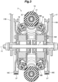
- each omnidirectional wheel 3 includes a frame 17, a pair of drive disks 18 rotatably supported by the frame 17, and an annular main wheel 19 disposed between the drive disks 18.
- the frame 17 includes a frame upper portion 17A fixed to the lower portion of the main body 2, and a pair of frame side portions 17B respectively extending downward from the left and right ends of the frame upper portion 17A.
- a support shaft 21 extends laterally between the lower ends of the frame side portions 17B.
- Each of the drive disks 18 is rotatably supported on the support shaft 21.
- the drive disks 18 are disposed on both sides of the annular main wheel 19 and apply frictional force to the main wheel 19 to rotate the main wheel 19 about a central axis and an annular axis.
- Each drive disk 18 includes a disk-shaped base 18A rotatably supported by the frame 17 and multiple drive rollers 18B rotatably supported on the outer periphery of the base 18A while being inclined with respect to each other and in contact with the main wheel 19.
- the base 18A is disposed coaxially with the support shaft 21.
- the main wheel 19 has an annular shape, is disposed between the drive disks 18 to be coaxial with the drive disks 18, is in contact with the multiple drive rollers 18B, and is rotatable about the central axis and the annular axis.
- the main wheel 19 includes an annular core 31 and multiple driven rollers 32 rotatably supported by the core 31.
- the multiple driven rollers 32 are arranged at equal intervals in the circumferential direction of the core 31.
- Each driven roller 32 is supported by the core 31 to be rotatable about an axis A1 (annular axis) of the annular core 31.
- Each driven roller 32 can rotate about a tangent line on the core 31 at its respective position relative to the core 31.
- Each driven roller 32 rotates with respect to the core 31 upon receiving an external force.
- the main wheel 19 is disposed along the outer periphery of the pair of drive disks 18 and is in contact with the multiple drive rollers 18B provided on each drive disk 18.
- the drive rollers 18B of the left and right drive disks 18 contact the inner periphery of the main wheel 19 and sandwich the main wheel 19 from left and right sides. Further, the drive rollers 18B of the left and right drive disks 18 restrict the radial displacement of the main wheel 19 about the axis Y1 of the drive disks 18 by contacting the inner periphery of the main wheel 19. In this way, the main wheel 19 is supported by the left and right drive disks 18, and the central axis of the main wheel 19 (core 31) is disposed coaxially with the axis Y1 of the left and right drive disks 18. The main wheel 19 contacts the multiple drive rollers 18B of the left and right drive disks 18 at the multiple driven rollers 32.
- the drive units 6 are installed in the main body 2 and output a driving force for driving the corresponding omnidirectional wheels 3.
- the drive units 6 preferably include electric motors 35 for driving the omnidirectional wheels 3 independently from each other by using the electric power supplied from the battery installed in the cart 1 based on the signal from the controller 8.
- the drive units 6 are provided under the main body 2 to correspond to the respective omnidirectional wheels 3. Since two omnidirectional wheels 3 are provided, two drive units 6 are provided on the cart 1, and each drive unit 6 is provided with two electric motors 35 corresponding to the two drive disks 18 of each omnidirectional wheel 3, as shown in Figure 5 . Thus, the cart 1 is provided with four electric motors 35 in total.
- a power transmission mechanism is provided between each of the two electric motors 35 of the drive unit 6 and the corresponding one of the two drive disks 18 of the omnidirectional wheel 3.
- the power transmission mechanism is composed of a drive pulley 36 provided on the output shaft of the electric motor 35, a driven pulley 18C provided on the outward facing surface of the drive disk 18 in a coaxial manner, and a belt 27 wound between the drive pulley 36 and the driven pulley 18C.
- the two electric motors 35 of each drive unit 6 are rotated independently from each other, whereby the two drive disks 18 of each omnidirectional wheel 3 are rotated independently from each other.
- the main wheel 19 rotates together with the two drive disks 18. That is, the main wheel 19 rotates forward or backward about its own rotation axis which coincides with the axis Y1. In this way, the main wheel 19 generates a driving force in the front-rear direction. At this time, the drive rollers 18B of each drive disk 18 and the driven rollers 32 of the main wheel 19 do not rotate with respect to the core 31.
- the cart 1 When the two drive units 6 cause the left and right omnidirectional wheels 3 to rotate forward (or backward) with a rotation speed difference therebetween, the cart 1 turns right or left. When the two drive units 6 cause the left and right omnidirectional wheels 3 to rotate in opposite directions at the same rotation speed, the cart 1 turns (spins) there. When the two drive units 6 each cause the driven rollers 32 of the main wheel 19 of the corresponding omnidirectional wheel 3 to rotate to exert a driving force in the same left direction (right direction), the cart 1 undergoes a translational movement to the left (to the right).
- the swivel casters 5 are casters that are swivelable and are provided under the main body 2.
- the swivel casters 5 are preferably supported under the main body 2 via a suspension 40.
- the swivel casters 5 are provided on the front portion 2B of the main body 2 to be positioned forward of the omnidirectional wheels 3.
- the suspension 40 includes an arm 42 disposed below the main body 2 and extending laterally, and a spring 43 (also called a cushion spring) and a shock absorber 45 (also called a damper) disposed between the main body 2 and the arm 42.
- a spring 43 also called a cushion spring
- a shock absorber 45 also called a damper
- the swivel casters 5 are disposed below the left end and the right end of the arm 42.
- Each swivel caster 5 includes a fork 42A joined to the arm 42 to be rotatable about an axis L1 that extends vertically, and a disk-shaped wheel 42B supported by the fork 42A to be rotatable about an axis L2 that extends in the horizontal direction.
- the fork 42A rotates (turns) freely relative to the arm 42 about the axis L1, and the wheel 42B rotates freely relative to the fork 42A.
- the wheel 42B is supported on the main body 2 to be swivelable about the axis L1 which extends in the up-down direction and to be rotatable about the axis L2 which extends in the horizontal direction.
- a ground contact position P1 of each swivel caster 5 changes with rotation of the fork 42A about the axis L1.
- each omnidirectional wheel 3 is supported on the main body 2 via the frame 17. Since the frame 17 is fixed to the main body 2, the position of each omnidirectional wheel 3 does not change, and a ground contact position P2 of the omnidirectional wheel 3 with respect to the center of gravity G of the cart 1 does not change.
- the controller 8 is a so-called electronic control unit (ECU) and is composed of a computer including a processor 50, such as a central processing unit (CPU) and a micro processor unit (MPU), a memory 56 such as a non-volatile memory 52 (e.g., a read-only memory (ROM)) and a volatile memory 54 (e.g., a random access memory (RAM)), and a storage device 58 such as a hard disk drive (HDD) and a solid state drive (SSD), as shown in Figure 6 .
- the controller 8 is mounted to the main body 2 and is connected to each of the drive units 6 and a battery (not shown in the drawings).
- the controller 8 may be configured by a single piece of hardware or may be configured as a unit composed of multiple pieces of hardware. Also, at least some of the functional units of the controller 8 may be realized by hardware such as an LSI, an ASIC, an FPGA, etc., or may be realized by the combination of software and hardware.
- the controller 8 controls the drive units 6 to control the travel of the cart 1 by executing, with the processor 50, the computational processing in accordance with programs stored in the memory 56 and the storage device 58.
- the controller 8 executes a provisional velocity setting process of calculating, based on the detection result of the input sensor 10, a velocity in the x direction required of the cart 1 (hereinafter, the provisional longitudinal velocity v x ), a velocity in the y direction required of the cart 1 (hereinafter, the provisional lateral velocity v y ), and an angular velocity about the z axis passing through the center of gravity G required of the cart 1 (hereinafter, the provisional yaw rate w z ).
- the controller 8 sets a target lateral velocity v y ', a target longitudinal velocity v x ', and a target yaw rate w z ' at which the cart 1 can travel stably based on the provisional lateral velocity v y , the provisional longitudinal velocity v x , and the provisional yaw rate w z , and executes a velocity control process of controlling the drive unit 6 such that the cart 1 moves at the target lateral velocity v y ', the target longitudinal velocity v x ', and the target yaw rate w z '. Thereby, the cart 1 is prevented from spinning and stable travel of the cart 1 is realized.
- the controller 8 includes, as functional units thereof, a provisional velocity determination unit 62 and a storage unit 64 for storing various parameters, as shown in Figure 5 . Also, to execute the velocity control process, the controller 8 includes, in addition to the storage unit 64, an estimation unit 66 configured to estimate the distance between the ground contact position P1 of each swivel caster 5 and the center of gravity G of the cart 1 in the front-rear direction, a limit velocity calculation unit 68 configured to calculate a stability limit velocity V max by using the distance estimated by the estimation unit 66, a target velocity setting unit 70 configured to calculate a target velocity based on the stability limit velocity, and a driving control unit 72 configured to control the drive units 6.
- an estimation unit 66 configured to estimate the distance between the ground contact position P1 of each swivel caster 5 and the center of gravity G of the cart 1 in the front-rear direction
- a limit velocity calculation unit 68 configured to calculate a stability limit velocity V max by using the distance estimated by the estimation unit 66
- Each of these functional units namely, the provisional velocity determination unit 62, the estimation unit 66, the limit velocity calculation unit 68, the target velocity setting unit 70, and the driving control unit 72, is realized by executing a predetermined program with the processor 50.
- the storage unit 64 is composed of the storage device 58 and/or the memory 56.
- the provisional velocity determination unit 62 calculates, based on the detection result of the input sensor 10, the provisional lateral velocity v y , which is a tentative moving velocity in the left-right direction, the provisional longitudinal velocity v x , which is a tentative moving velocity in the front-rear direction, and the provisional yaw rate w z , which is a tentative yaw rate.
- the provisional velocity determination unit 62 may set the provisional yaw rate w z to zero, the provisional lateral velocity v y to be proportional to the lateral load, and the provisional longitudinal velocity v x to be proportional to the longitudinal load, so as to cause the cart 1 to undergo a translational movement.
- the provisional velocity determination unit 62 may set the provisional longitudinal velocity v x to be proportional to the longitudinal load and the provisional yaw rate w z to be proportional to the lateral load, so as to turn the cart 1.
- the provisional velocity determination unit 62 may determine in advance a reference point where the longitudinal velocity, the lateral velocity, and the yaw rate are to be set, convert the longitudinal load, the lateral load, and the yaw moment acquired by the input sensor 10 into the longitudinal load, the lateral load, and the yaw moment at the reference point, and set the provisional longitudinal velocity v x at the reference point to be proportional to the longitudinal load at the reference point, the provisional lateral velocity v y at the reference point to be proportional to the lateral load at the reference point, and the provisional yaw rate w z at the reference point to be proportional to the yaw moment at the reference point.
- the reference point may be set to the center of gravity G, for example.
- the provisional velocity determination unit 62 may determine the provisional lateral velocity v y , the provisional longitudinal velocity v x , and the provisional yaw rate w z based on an input to a terminal from the operator who operates the cart 1.
- the provisional velocity determination unit 62 may autonomously determine the provisional lateral velocity v y , the provisional longitudinal velocity v x , and the provisional yaw rate w z based on the set travel route and the detection result of sensors (such as a camera, a radar, a lidar, etc.) for detecting objects or the like located in the surroundings.
- sensors such as a camera, a radar, a lidar, etc.
- the storage unit 64 stores data related to the travel control of the cart 1.
- the data stored in the storage unit 64 at least includes a mass m of the cart 1, a cornering power K ⁇ of the swivel caster 5, a cornering power K r of the omnidirectional wheel 3, and a distance L r from the ground contact position P2 of the omnidirectional wheel 3 to the center of gravity G in the front-rear direction (the distance in the front-rear direction may be also referred to as the front-rear distance).
- the cart 1 of the illustrated embodiment has a laterally symmetrical structure, and the cornering power K f is the same for the left and right swivel casters 5, the cornering power K r is the same for the left and right omnidirectional wheels 3, and the front-rear distance L r is the same for the left and right omnidirectional wheels 3. Therefore, the storage unit 64 may store the cornering power K ⁇ of one of the left and right swivel casters 5, the cornering power K r of one of the left and right omnidirectional wheels 3, and the front-rear distance L r from the ground contact position P2 of one of the omnidirectional wheel 3 to the center of gravity G.
- the cornering power means a rising gradient of a cornering force of the corresponding wheel (the omnidirectional wheel 3 or the swivel caster 5) with respect to the sideslip angle.
- the cornering force means a force in the lateral direction (namely, in a direction parallel to the axle) generated by the corresponding wheel during a turn (this force may be also referred to as a lateral force or a turning centripetal force).
- the storage unit 64 further stores a distance L 0 from the center of gravity G to the axis L1 in the front-rear direction and a distance d from the axis L1 to the ground contact position P1 of the wheel 42B of the swivel caster 5 (see Figure 2 ).
- the distance L 0 and the distance d are the same for the left and right swivel casters 5, and thus, the storage unit 64 may store the distance L 0 and the distance d regarding one of the left and right swivel casters 5.
- the estimation unit 66 estimates a distance from the ground contact position P1 of the swivel caster 5 to the center of gravity G in the front-rear direction (hereinafter, the caster distance L f ).
- the estimation unit 66 may preferably estimate the caster distance L f by averaging the front-rear distance from the ground contact position P1 of the left swivel caster 5 to the center of gravity G and the front-rear distance from the ground contact position P1 of the right swivel caster 5 to the center of gravity G.
- the estimation unit 66 may estimate the caster distance L f by using the following formula (1) (note that, in the formula (1), ⁇ fL represents the angle of the travel direction of the left swivel caster 5 with respect to the forward direction (0°), ⁇ fR represents the angle of the travel direction of the right swivel caster 5 with respect to the forward direction, and L s represents the distance from the axis L1 to the center of gravity G in the left-right direction).
- the limit velocity calculation unit 68 calculates the stability limit velocity V max below which the cart 1 can travel (move) stably. First of all, the limit velocity calculation unit 68 acquires the caster distance L f (the distance from the ground contact position P1 of the swivel caster 5 to the center of gravity G in the front-rear direction) estimated by the estimation unit 66, and acquires K ⁇ , K r , and L r from the storage unit 64.
- the limit velocity calculation unit 68 determines whether the following formula (2) is satisfied by using the acquired K f , K r , L f , and L r .
- the limit velocity calculation unit 68 acquires the mass m of the cart 1 stored in the storage unit 64, and calculates the stability limit velocity V max by using the following formula (3).
- V max 2 K f K r L f + L r 2 m K f L f ⁇ K r L r
- the stability limit velocity V max represents the limit velocity (speed) below which the cart 1 can travel stably when the formula (2) is satisfied. It can be said that the formula (2) represents a calculation condition for the limit velocity calculation unit 68 to calculate the stability limit velocity V max .
- the target velocity setting unit 70 sets the provisional lateral velocity v y , the provisional longitudinal velocity v x , and the provisional yaw rate w z as the target lateral velocity v y ', the target longitudinal velocity v x ', and the target yaw rate w z '.
- the target velocity setting unit 70 calculates a coefficient R by using the following formula (4).
- R ⁇ 1 v x 2 + v y 2 ⁇ v ⁇ V max
- V max v x 2 + v y 2 v x 2 + v y 2 v ⁇ V max
- the coefficient R is set to 1, and when the magnitude of the provisional velocity is greater than or equal to the stability limit velocity V max , the coefficient R is set to a value obtained by dividing the stability limit velocity V max by the magnitude of the provisional velocity (V max / v).
- the target velocity setting unit 70 may calculate the coefficient R by using the following formula (5).
- R min V max v x 2 + v y 2 , 1
- min ⁇ a, b ⁇ in the formula (5) represents the minimum value of ⁇ a, b ⁇ (smaller value of a and b).
- the target velocity setting unit 70 multiplies each of the provisional lateral velocity v y , the provisional longitudinal velocity v x , and the provisional yaw rate w z by the coefficient R, and sets them as the target lateral velocity v y ', the target longitudinal velocity v x ', and the target yaw rate w z '. Namely, the target velocity setting unit 70 acquires the target lateral velocity v y ', the target longitudinal velocity v x ', and the target yaw rate w z ' by using the following formula (6).
- the target lateral velocity v y ', the target longitudinal velocity v x ', and the target yaw rate w z ' are set to values obtained by multiplying the provisional lateral velocity v y , the provisional longitudinal velocity v x , and the provisional yaw rate w z by the coefficient R, respectively.
- v x ′ Rv x
- v y ′ Rv y
- ⁇ z ′ R ⁇ z
- the driving control unit 72 controls the drive unit 6 so that the cart 1 travels at the target lateral velocity v y ', the target longitudinal velocity v x ', and the target yaw rate w z ' set by the target velocity setting unit 70.
- the controller 8 calculates the provisional lateral velocity v y , the provisional longitudinal velocity v x , and the provisional yaw rate w z based on the input to the input sensor 10.
- the controller 8 executes the velocity control process.
- the controller 8 executes the velocity control process every time the calculation of the provisional lateral velocity v y , the provisional longitudinal velocity v x , and the provisional yaw rate w z is performed.
- the processor 50 of the controller 8 estimates the caster distance L ⁇ based on the provisional lateral velocity v y , the provisional longitudinal velocity v x , and the provisional yaw rate w z .
- the processor 50 of the controller 8 may estimate the caster distance L f by using the formula (1).
- the processor 50 of the controller 8 executes step ST2.
- step ST2 the processor 50 acquires, from the storage device 58, the cornering power K ⁇ of the swivel caster 5, the distance L r between the ground contact position P2 of the omnidirectional wheel 3 and the center of gravity G in the front-rear direction, and the cornering power K r of the omnidirectional wheel 3. Upon completion of the acquisition, the processor 50 executes step ST3.
- step ST3 the processor 50 (the limit velocity calculation unit 68) determines whether the formula (2) (namely, K f L f - K r L r > 0) is satisfied by using L ⁇ acquired in ST1 and K ⁇ , K r , and L r acquired in ST2.
- the processor 50 executes step ST4
- the processor 50 executes step ST5.
- step ST4 the processor 50 (the limit velocity calculation unit 68) calculates the stability limit velocity V max by using the formula (5). Upon completion of the calculation, the processor 50 executes the step ST6.
- step ST5 the processor 50 (the target velocity setting unit 70) sets the provisional lateral velocity v y as the target lateral velocity v y ', sets the provisional longitudinal velocity v x as the target longitudinal velocity v x ', and sets the provisional yaw rate w z as the target yaw rate w z '.
- the processor 50 executes step ST7.
- step ST6 the processor 50 (the target velocity setting unit 70) determines whether the magnitude of the provisional velocity v is less than the stability limit velocity V max .
- the processor 50 executes step ST8, and when the magnitude of the provisional velocity v is greater than or equal to the stability limit velocity V max , the processor 50 executes step ST9.
- step ST7 the processor 50 (the driving control unit 72) controls the drive unit 6 so that the cart 1 travels at the target lateral velocity v y ', the target longitudinal velocity v x ', and the target yaw rate w z '.
- the processor 50 ends the velocity control process.
- step ST8 the processor 50 (the target velocity setting unit 70) sets the coefficient R to 1. Upon completion of the setting of the coefficient R, the processor 50 executes step ST10.
- step ST9 the processor 50 (the target velocity setting unit 70) sets the coefficient R to a value obtained by dividing the stability limit velocity V max by the magnitude of the provisional velocity v.
- the processor 50 executes step ST10.
- step ST10 the processor 50 (the target velocity setting unit 70) sets the target lateral velocity v y ', the target longitudinal velocity v x ', and the target yaw rate w z ' by using the formula (8). Specifically, the processor 50 sets the target lateral velocity v y ' to a value obtained by multiplying the provisional lateral velocity v y by R, sets the target longitudinal velocity v x ' to a value obtained by multiplying the provisional longitudinal velocity v x by R, and sets the target yaw rate w z ' to a value obtained by multiplying the provisional yaw rate w z by R.
- the processor 50 executes step ST7 to control the drive unit 6 so that the cart 1 travels at the target lateral velocity v y ', the target longitudinal velocity v x ', and the target yaw rate w z '.
- the processor 50 ends the velocity control process.
- the controller 8 calculates the provisional lateral velocity v y , the provisional longitudinal velocity v x , and the provisional yaw rate w z based on the input to the input sensor 10. Thereafter, the controller 8 executes the velocity control process. In the velocity control process, the controller 8 sets the target lateral velocity v y ', the target longitudinal velocity v x ', and the target yaw rate w z '.
- the coefficient R is set to a value less than or equal to 1, and therefore, the velocity of the cart 1 is limited to be less than or equal to the stability limit velocity.
- the motion of the cart 1 can be described by the equation of motion represented by the following formula (7).
- V x represents the x component of the velocity of the cart 1
- V y represents the y component of the velocity of the cart 1
- W z represents the angular velocity about the z axis passing through the center of gravity G of the cart 1
- "•" represents a time derivative.
- I z represents the moment of inertia about the z axis passing through the center of gravity G of the cart 1
- F fL and F fR represent the lateral force applied to the left and right swivel casters 5, respectively
- F rL and F rR represent the lateral force applied to the left and right omnidirectional wheels 3, respectively.
- each lateral force can be expressed by a product of the sideslip angle ⁇ and the related cornering power, and suppose that the sideslip angle ⁇ is sufficiently small, V x can be approximated by the square root of the sum of the square of V x and the square of V y (namely, the speed V), and V y can be approximated by V ⁇ , and hence, the following formula (8) can be obtained.
- Ge(s) and Gw(s) each correspond to a transfer function.
- D(s) in the formula (10) is represented by the following formula (11).
- the shaded region in Figure 8B indicates a region in which the formula (12) is satisfied, namely, a stable velocity range in which the travel of the cart 1 is stable, in a graph with a horizontal axis representing L ⁇ and a vertical axis representing V 2 .
- Such analysis of the traveling stability of the cart 1 using D(s) is referred to herein as the stability analysis.
- ⁇ and S2 respectively represent ⁇ (0) and W z (0), which are values of ⁇ and W z when 0 is substituted for s in the formula (10).
- the attractor is proportional to the steering angle ⁇ .
- Ce(V, L ⁇ ) and C wz (V, L ⁇ ) can be considered to represent the sensitivity of the sideslip angle ⁇ and the angular velocity W z to the steering angle ⁇ .
- the traveling stability of the cart 1 is classified into the following three patterns (i) to (iii).
- the formula (12) holds when the speed V of the cart 1 is less than or equal to the stability limit velocity V max .
- the processor 50 sets the stability limit velocity V max , and limits the square root of the sum of the square of the target lateral velocity v y ' and the square of the target longitudinal velocity v x ' to be less than or equal to the stability limit velocity V max . Accordingly, the velocity of the cart 1 becomes less than or equal to the stability limit velocity V max , and stable travel of the cart 1 is realized.
- Figure 13 shows an example in which calibration of the omnidirectional wheels 3 of the cart 1 is performed.
- “Calibration” here means a process for acquiring correction factors to correct the difference between the command value for the driving amount of each omnidirectional wheel 3 from the corresponding drive unit 6 and the actual driving amount of the omnidirectional wheel 3.
- Figure 13 shows the difference between a theoretical value (estimated value) of the yaw angle according to the command value and a measured value (odometry value) of the yaw angle according to the odometry method for various movements of the cart 1 including backward movement, by using the correction factors obtained by the calibration.
- the difference between the theoretical value (estimated value) and the measured value is small, and appropriate correction is possible.
- the controller 8 was configured to execute the velocity control process regardless of the magnitude of the provisional yaw rate w z , but in another embodiment, the controller 8 may be configured to execute the velocity control process when the magnitude of the provisional yaw rate w z is greater than or equal to a predetermined threshold value (hereinafter, the yaw rate threshold value).
- the yaw rate threshold value a predetermined threshold value
- the calculation condition for the limit velocity calculation unit 68 to calculate the stability limit velocity V max includes that K f L f - K r L r > 0 and that the magnitude of the provisional yaw rate is greater than or equal to the yaw rate threshold value.
- the cart 1 when the cart 1 turns, the velocity is prevented from exceeding the stability limit velocity V max , so that spin of the vehicle can be prevented.
- the velocity during translational movement (during translation) is not limited to be less than or equal to the stability limit velocity, the cart 1 can be moved quickly.
- the swivel caster 5 may be provided with a rotation angle sensor 90 (see Figures 12A and 12B ) to detect the rotation angle of the fork 42A.
- the estimation unit 66 may calculate (estimate) the caster distance L f based on the rotation angle detected by the rotation angle sensor 90.
- the present invention is not limited to the above embodiments and various modifications and alterations are possible.
- the mobile body according to the present invention is embodied as the cart 1
- the present invention may be applicable to any mobile body that is configured to move on a road surface.
- the present invention is applicable to a vehicle such as a wheelchair, a wagon for transporting goods, etc.
Landscapes
- Engineering & Computer Science (AREA)
- Mechanical Engineering (AREA)
- Transportation (AREA)
- Chemical & Material Sciences (AREA)
- Combustion & Propulsion (AREA)
- Power Engineering (AREA)
- Control Of Position, Course, Altitude, Or Attitude Of Moving Bodies (AREA)
- Handcart (AREA)
Abstract
Description
- The present invention relates to a mobile body.
-
WO2021/039918A1 discloses a cart having two rotation mechanisms and four wheels. The two rotation mechanisms rotate independently from each other to move the main body. The four wheels rotate along with the movement of the main body. - It may be conceived to configure a mobile body having two left and right driving wheels as rear wheels and two left and right swivel casters as front wheels by using a rotation mechanism similar to that disclosed in
WO2021/039918A1 as each of the driving wheels. However, the inventors found that in such a mobile body, depending on the driving state of the rotation mechanisms, the travel direction of the mobile body, and the like, the main body of the mobile body may spin or otherwise the traveling of the mobile body can be unstable. - In view of the foregoing background, a primary object of the present invention is to provide a mobile body that can travel stably.
- To achieve the above object, one aspect of the present invention provides a mobile body (1), comprising: a main body (2); a pair of left and right driving wheels (3) provided on the main body; a drive unit (6) configured to drive each of the driving wheels; a pair of left and right swivel casters (5) respectively provided in front of the driving wheels, and each supported on the main body to be swivelable about an axis extending in an up-down direction; and a controller (8) configured to control the drive unit, wherein the controller comprises: an estimation unit (66) configured to estimate a front-rear distance between a ground contact position (P 1) of the swivel caster and a center of gravity (G); a limit velocity calculation unit (68) configured to calculate a stability limit velocity (Vmax) based on the front-rear distance (Lε) estimated by the estimation unit, a front-rear distance (Lr) between a ground contact position (P2) of the driving wheel and the center of gravity, a cornering power (Kr) of the driving wheel, and a cornering power (Kf) of the swivel caster when a predetermined calculation condition is satisfied; and a driving control unit (72) configured to control the drive unit such that a velocity of the mobile body is less than or equal to the stability limit velocity when the stability limit velocity is calculated by the limit velocity calculation unit.
- According to this aspect, since the velocity of the mobile body is controlled to be less than or equal to the stability limit velocity when the stability limit velocity is calculated, a mobile body that can travel stably is provided.
- In the above aspect, preferably, the limit velocity calculation unit calculates the stability limit velocity according to a formula (A) below,

- According to this aspect, the stability limit velocity can be properly calculated.
- In the above aspect, preferably, each driving wheel is an omnidirectional wheel capable of translational movement in a left-right direction.
- According to this aspect, the mobile body can undergo a translational movement in all directions.
- In the above aspect, preferably, the calculation condition includes KfLf - KrLr > 0.
- According to this aspect, the calculation condition in which the calculation of the stability limit velocity is necessary can be properly acquired.
- In the above aspect, preferably, the mobile body comprises: an input sensor (10) provided on the main body to receive an operation input regarding an operation of the mobile body from an operator; a provisional velocity determination unit (62) configured to calculate a provisional velocity, which is a tentative moving velocity, based on the operation input acquired by the input sensor; and a target velocity setting unit (70) configured to determine a target velocity based on the provisional velocity calculated by the provisional velocity determination unit, wherein when the stability limit velocity is calculated by the limit velocity calculation unit and a magnitude of the provisional velocity calculated by the provisional velocity determination unit is greater than a magnitude of the stability limit velocity, the target velocity setting unit calculates a coefficient by dividing the magnitude of the stability limit velocity by the magnitude of the provisional velocity and acquires the target velocity by multiplying the provisional velocity by the coefficient, and the driving control unit controls the drive unit so as to cause the mobile body to move at the target velocity.
- According to this aspect, the velocity of the mobile body can be limited within a velocity range in which a stable movement is possible.
- In the above aspect, preferably, the provisional velocity determination unit calculates a provisional yaw rate, which is a tentative yaw rate, based on the operation input, the target velocity setting unit acquires a target yaw rate by multiplying the provisional yaw rate by the coefficient when the stability limit velocity is calculated by the limit velocity calculation unit and the magnitude of the provisional velocity is greater than the magnitude of the stability limit velocity, and the driving control unit controls the drive unit such that a yaw rate of the mobile body becomes the target yaw rate.
- According to this aspect, when limiting the velocity of the mobile body within the velocity range in which a stable movement is possible, the yaw rate of the mobile body can be properly set.
- In the above aspect, preferably, the calculation condition is that KfLf - KrLr > 0 and a magnitude of the provisional yaw rate is greater than or equal to a predetermined threshold value.
- According to this aspect, a timing when the velocity of the mobile body should be limited so that a stable movement of the mobile body is possible can be properly acquired.
- In the above aspect, preferably, the estimation unit estimates a direction of a wheel (42B) of each swivel caster based on the provisional velocity and estimates the front-rear distance between the ground contact position of the swivel caster and the center of gravity based on the direction of the wheel of each swivel caster.
- According to this aspect, in a case where the ground contact position of each swivel caster changes depending on the direction of the swivel caster, the stability limit velocity can be properly calculated.
- According to the foregoing configuration, it is possible to provide a mobile body that can travel stably.
-
-
Figure 1 shows a perspective view of a cart according to an embodiment of the present invention in part (A) thereof, and a partial enlarged view of a swivel caster of the cart in part (B) thereof; -
Figure 2 is a plan view of the cart; -
Figure 3 is a sectional view of an omnidirectional wheel; -
Figure 4 is a side view of a main wheel; -
Figure 5 is a functional block diagram of the cart; -
Figure 6 is a block diagram of a controller; -
Figure 7 is a flowchart showing a velocity control process executed by the controller; -
Figure 8A is a graph showing the s-dependency of D(s); -
Figure 8B is a graph showing a stable velocity range, with the horizontal axis representing Lε and the vertical axis representing V2; -
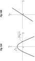
Figure 9A is a graph showing the V-dependency of Ce(V, Lε) when KfLf - KrLr < 0; -
Figure 9B is a graph showing the V-dependency of Cwz(V, Lε) when KfLf - KrLr < 0; -
Figure 10A is a graph showing the V-dependency of Ce(V, Lε) when KfLf - KrLr = 0; -
Figure 10B is a graph showing the V-dependency of Cwz(V, Lε) when KfLf - KrLr = 0; -
Figure 11A is a graph showing the V-dependency of Ce(V, Lε) when KfLf - KrLr > 0; -
Figure 11B is a graph showing the V-dependency of Cwz(V, Lε) when KfLf - KrLr > 0; -
Figure 12A is a side view showing a posture of the swivel caster during forward movement; -
Figure 12B is a side view showing a posture of the swivel caster during backward movement; and -
Figure 13 is a graph showing a measured value (odometry value) and an estimated value of the yaw angle for various movements after calibration. - In the following, an embodiment in which a mobile body according to the present invention is embodied as a
cart 1 will be described with reference to the drawings. Note, however, that the mobile body according to the present invention is not limited to thecart 1, and the present invention may be applicable to any vehicle, such as a wheelchair, a wagon for carrying goods, etc., for example. - The
cart 1 is a mobile body used to carry and transport goods, and is provided on one end thereof with a handle H for an operator to grip. When the operator grips the handle H and pushes forward, thecart 1 is self-propelled forward according to a load inputted from the operator. - In the following, description will be made of with the front, rear, left, right, up, and down directions of the
cart 1 being defined based on the state in which thecart 1 is placed on a horizontal surface as shown in part (A) ofFigure 1 , where the side on which the handle H is provided is defined as a rear side. Note, however, that the definition of the directions is for convenience of explanation, and the present invention is not limited by such definition of the directions. Also, in the following, description may be made with the forward direction being referred to as an x axis positive direction, the left direction being referred to as a y axis positive direction, and the upward direction being referred to as a z axis positive direction when necessary, but the present invention is also not limited by such association of directions with the coordinate axes. - Further, in the following description, it is assumed for the sake of simplicity that the weight of the
cart 1 is sufficiently greater than the weight of the goods placed on thecart 1, and that the position of the center of gravity of thecart 1 on which the goods are loaded is substantially the same as the position of the center of gravity of thecart 1 on which no goods are loaded. - Next, the structure of the
cart 1 will be described in detail. - As shown in part (A) of
Figure 1 andFigure 2 , thecart 1 includes amain body 2, a pair of left and rightomnidirectional wheels 3 serving as driving wheels, a pair of left and rightswivel casters 5 serving as non-driving wheels (see also part (B) ofFigure 1 ), a pair ofdrive units 6 for driving the correspondingomnidirectional wheels 3, and acontroller 8 for controlling thedrive units 6. - The
main body 2 has a substantially rectangular parallelepiped shape extending in the front-rear direction. An upper surface of a front portion of themain body 2 constitutes a substantially horizontal and flat load bed. Arear portion 2A of themain body 2 protrudes upward compared to afront portion 2B. The handle H is provided on the upper end of therear portion 2A of themain body 2. - The
main body 2 is further provided with aninput sensor 10 for detecting an operation input from the operator to the handle H and outputting the detection result to thecontroller 8. - The
input sensor 10 is preferably composed of aforce sensor 12 for detecting the force and/or moment applied to the handle H. Theforce sensor 12 may be a known six-axis force sensor of any type, such as a strain gauge type, a piezoelectric type, an optical type, an electrostatic capacitance type, etc. In the present embodiment, theforce sensor 12 detects a load in the front-rear direction (hereinafter, the longitudinal load), a load in the left-right direction (hereinafter, the lateral load), and a moment about an up-down axis (z axis) (yaw moment) that are applied to the handle H, and outputs them to thecontroller 8. When thecart 1 is placed on a horizontal surface, the up-down axis corresponds to the vertical axis. - The pair of
omnidirectional wheels 3 is provided on a lower portion of therear portion 2A of themain body 2. In the present embodiment, theomnidirectional wheels 3 are disposed under a left part and a right part of therear portion 2A of themain body 2, respectively. Theomnidirectional wheels 3 are wheels for causing themain body 2 to undergo a translational movement (translation) in the front-rear direction or the left-right direction or for causing themain body 2 to turn (spin turn). Theomnidirectional wheels 3 are preferably composed of omni wheels or mecanum wheels, for example. - As shown in
Figure 3 , in the present embodiment, eachomnidirectional wheel 3 includes aframe 17, a pair ofdrive disks 18 rotatably supported by theframe 17, and an annularmain wheel 19 disposed between thedrive disks 18. - The
frame 17 includes a frameupper portion 17A fixed to the lower portion of themain body 2, and a pair offrame side portions 17B respectively extending downward from the left and right ends of the frameupper portion 17A. Asupport shaft 21 extends laterally between the lower ends of theframe side portions 17B. Each of thedrive disks 18 is rotatably supported on thesupport shaft 21. - The
drive disks 18 are disposed on both sides of the annularmain wheel 19 and apply frictional force to themain wheel 19 to rotate themain wheel 19 about a central axis and an annular axis. Eachdrive disk 18 includes a disk-shapedbase 18A rotatably supported by theframe 17 andmultiple drive rollers 18B rotatably supported on the outer periphery of thebase 18A while being inclined with respect to each other and in contact with themain wheel 19. Thebase 18A is disposed coaxially with thesupport shaft 21. - As shown in
Figure 4 , themain wheel 19 has an annular shape, is disposed between thedrive disks 18 to be coaxial with thedrive disks 18, is in contact with themultiple drive rollers 18B, and is rotatable about the central axis and the annular axis. Themain wheel 19 includes anannular core 31 and multiple drivenrollers 32 rotatably supported by thecore 31. The multiple drivenrollers 32 are arranged at equal intervals in the circumferential direction of thecore 31. Each drivenroller 32 is supported by the core 31 to be rotatable about an axis A1 (annular axis) of theannular core 31. Each drivenroller 32 can rotate about a tangent line on the core 31 at its respective position relative to thecore 31. Each drivenroller 32 rotates with respect to the core 31 upon receiving an external force. - The
main wheel 19 is disposed along the outer periphery of the pair ofdrive disks 18 and is in contact with themultiple drive rollers 18B provided on eachdrive disk 18. Thedrive rollers 18B of the left andright drive disks 18 contact the inner periphery of themain wheel 19 and sandwich themain wheel 19 from left and right sides. Further, thedrive rollers 18B of the left andright drive disks 18 restrict the radial displacement of themain wheel 19 about the axis Y1 of thedrive disks 18 by contacting the inner periphery of themain wheel 19. In this way, themain wheel 19 is supported by the left andright drive disks 18, and the central axis of the main wheel 19 (core 31) is disposed coaxially with the axis Y1 of the left andright drive disks 18. Themain wheel 19 contacts themultiple drive rollers 18B of the left andright drive disks 18 at the multiple drivenrollers 32. - The
drive units 6 are installed in themain body 2 and output a driving force for driving the correspondingomnidirectional wheels 3. Thedrive units 6 preferably includeelectric motors 35 for driving theomnidirectional wheels 3 independently from each other by using the electric power supplied from the battery installed in thecart 1 based on the signal from thecontroller 8. - In the present embodiment, the
drive units 6 are provided under themain body 2 to correspond to the respectiveomnidirectional wheels 3. Since twoomnidirectional wheels 3 are provided, twodrive units 6 are provided on thecart 1, and eachdrive unit 6 is provided with twoelectric motors 35 corresponding to the twodrive disks 18 of eachomnidirectional wheel 3, as shown inFigure 5 . Thus, thecart 1 is provided with fourelectric motors 35 in total. - To transmit the output of each
drive unit 6 to the correspondingomnidirectional wheel 3, a power transmission mechanism is provided between each of the twoelectric motors 35 of thedrive unit 6 and the corresponding one of the twodrive disks 18 of theomnidirectional wheel 3. As shown inFigures 1 and3 , the power transmission mechanism is composed of adrive pulley 36 provided on the output shaft of theelectric motor 35, a drivenpulley 18C provided on the outward facing surface of thedrive disk 18 in a coaxial manner, and abelt 27 wound between thedrive pulley 36 and the drivenpulley 18C. The twoelectric motors 35 of eachdrive unit 6 are rotated independently from each other, whereby the twodrive disks 18 of eachomnidirectional wheel 3 are rotated independently from each other. - When the two
electric motors 35 included in eachdrive unit 6 are driven to rotate the corresponding twodrive disks 18 in the same direction at the same rotation speed, themain wheel 19 rotates together with the twodrive disks 18. That is, themain wheel 19 rotates forward or backward about its own rotation axis which coincides with the axis Y1. In this way, themain wheel 19 generates a driving force in the front-rear direction. At this time, thedrive rollers 18B of eachdrive disk 18 and the drivenrollers 32 of themain wheel 19 do not rotate with respect to thecore 31. - When the two
electric motors 35 included in eachdrive unit 6 are driven to rotate the corresponding twodrive disks 18 such that a rotation speed difference occurs therebetween, a force component perpendicular to the force in the circumferential (tangential) direction caused by the rotation of the twodrive disks 18 acts on the drivenrollers 32 of themain wheel 19 from the left andright drive rollers 18B. Such a force component is generated due to the rotation speed difference between thedrive disks 18 because the axis of eachdrive roller 18B is inclined with respect to the circumferential direction of the associateddrive disk 18. This force component causes thedrive rollers 18B to rotate relative to thebase 18A and the drivenrollers 32 to rotate relative to thecore 31. In this way, themain wheel 19 generates a driving force in the left-right direction. - When the two
drive units 6 cause the correspondingomnidirectional wheels 3 to rotate forward at the same speed, thecart 1 moves forward (undergoes forward translation). When the twodrive units 6 cause the correspondingomnidirectional wheels 3 to rotate backward at the same speed, thecart 1 moves backward (undergoes backward translation). - When the two
drive units 6 cause the left and rightomnidirectional wheels 3 to rotate forward (or backward) with a rotation speed difference therebetween, thecart 1 turns right or left. When the twodrive units 6 cause the left and rightomnidirectional wheels 3 to rotate in opposite directions at the same rotation speed, thecart 1 turns (spins) there. When the twodrive units 6 each cause the drivenrollers 32 of themain wheel 19 of the correspondingomnidirectional wheel 3 to rotate to exert a driving force in the same left direction (right direction), thecart 1 undergoes a translational movement to the left (to the right). - As shown in
Figure 1 , theswivel casters 5 are casters that are swivelable and are provided under themain body 2. Theswivel casters 5 are preferably supported under themain body 2 via asuspension 40. In the present embodiment, theswivel casters 5 are provided on thefront portion 2B of themain body 2 to be positioned forward of theomnidirectional wheels 3. - In the present embodiment, the
suspension 40 includes anarm 42 disposed below themain body 2 and extending laterally, and a spring 43 (also called a cushion spring) and a shock absorber 45 (also called a damper) disposed between themain body 2 and thearm 42. - The
swivel casters 5 are disposed below the left end and the right end of thearm 42. Eachswivel caster 5 includes afork 42A joined to thearm 42 to be rotatable about an axis L1 that extends vertically, and a disk-shapedwheel 42B supported by thefork 42A to be rotatable about an axis L2 that extends in the horizontal direction. Thefork 42A rotates (turns) freely relative to thearm 42 about the axis L1, and thewheel 42B rotates freely relative to thefork 42A. Thereby, thewheel 42B is supported on themain body 2 to be swivelable about the axis L1 which extends in the up-down direction and to be rotatable about the axis L2 which extends in the horizontal direction. - As shown in
Figure 1 , in the present embodiment, the axis L1 and the axis L2 do not intersect each other and are in a skew position. Therefore, a ground contact position P1 of eachswivel caster 5 changes with rotation of thefork 42A about the axis L1. - On the other hand, the
main wheel 19 of eachomnidirectional wheel 3 is supported on themain body 2 via theframe 17. Since theframe 17 is fixed to themain body 2, the position of eachomnidirectional wheel 3 does not change, and a ground contact position P2 of theomnidirectional wheel 3 with respect to the center of gravity G of thecart 1 does not change. - The
controller 8 is a so-called electronic control unit (ECU) and is composed of a computer including aprocessor 50, such as a central processing unit (CPU) and a micro processor unit (MPU), amemory 56 such as a non-volatile memory 52 (e.g., a read-only memory (ROM)) and a volatile memory 54 (e.g., a random access memory (RAM)), and astorage device 58 such as a hard disk drive (HDD) and a solid state drive (SSD), as shown inFigure 6 . Thecontroller 8 is mounted to themain body 2 and is connected to each of thedrive units 6 and a battery (not shown in the drawings). - The
controller 8 may be configured by a single piece of hardware or may be configured as a unit composed of multiple pieces of hardware. Also, at least some of the functional units of thecontroller 8 may be realized by hardware such as an LSI, an ASIC, an FPGA, etc., or may be realized by the combination of software and hardware. - As shown in
Figure 5 , thecontroller 8 controls thedrive units 6 to control the travel of thecart 1 by executing, with theprocessor 50, the computational processing in accordance with programs stored in thememory 56 and thestorage device 58. - Specifically, the
controller 8 executes a provisional velocity setting process of calculating, based on the detection result of theinput sensor 10, a velocity in the x direction required of the cart 1 (hereinafter, the provisional longitudinal velocity vx), a velocity in the y direction required of the cart 1 (hereinafter, the provisional lateral velocity vy), and an angular velocity about the z axis passing through the center of gravity G required of the cart 1 (hereinafter, the provisional yaw rate wz). - When the provisional velocity setting process is completed, the
controller 8 sets a target lateral velocity vy', a target longitudinal velocity vx', and a target yaw rate wz' at which thecart 1 can travel stably based on the provisional lateral velocity vy, the provisional longitudinal velocity vx, and the provisional yaw rate wz, and executes a velocity control process of controlling thedrive unit 6 such that thecart 1 moves at the target lateral velocity vy', the target longitudinal velocity vx', and the target yaw rate wz'. Thereby, thecart 1 is prevented from spinning and stable travel of thecart 1 is realized. - To execute the provisional velocity setting process, the
controller 8 includes, as functional units thereof, a provisionalvelocity determination unit 62 and astorage unit 64 for storing various parameters, as shown inFigure 5 . Also, to execute the velocity control process, thecontroller 8 includes, in addition to thestorage unit 64, anestimation unit 66 configured to estimate the distance between the ground contact position P1 of eachswivel caster 5 and the center of gravity G of thecart 1 in the front-rear direction, a limitvelocity calculation unit 68 configured to calculate a stability limit velocity Vmax by using the distance estimated by theestimation unit 66, a targetvelocity setting unit 70 configured to calculate a target velocity based on the stability limit velocity, and a drivingcontrol unit 72 configured to control thedrive units 6. - Each of these functional units, namely, the provisional
velocity determination unit 62, theestimation unit 66, the limitvelocity calculation unit 68, the targetvelocity setting unit 70, and the drivingcontrol unit 72, is realized by executing a predetermined program with theprocessor 50. Thestorage unit 64 is composed of thestorage device 58 and/or thememory 56. - In the following, each of the provisional
velocity determination unit 62, thestorage unit 64, theestimation unit 66, the limitvelocity calculation unit 68, the targetvelocity setting unit 70, and the drivingcontrol unit 72 will be described in detail. - The provisional
velocity determination unit 62 calculates, based on the detection result of theinput sensor 10, the provisional lateral velocity vy, which is a tentative moving velocity in the left-right direction, the provisional longitudinal velocity vx, which is a tentative moving velocity in the front-rear direction, and the provisional yaw rate wz, which is a tentative yaw rate. For example, when the lateral load acquired by theinput sensor 10 is greater than a predetermined threshold value, the provisionalvelocity determination unit 62 may set the provisional yaw rate wz to zero, the provisional lateral velocity vy to be proportional to the lateral load, and the provisional longitudinal velocity vx to be proportional to the longitudinal load, so as to cause thecart 1 to undergo a translational movement. On the other hand, when the lateral load acquired by theinput sensor 10 is less than or equal to the predetermined threshold value, the provisionalvelocity determination unit 62 may set the provisional longitudinal velocity vx to be proportional to the longitudinal load and the provisional yaw rate wz to be proportional to the lateral load, so as to turn thecart 1. Also, for example, the provisionalvelocity determination unit 62 may determine in advance a reference point where the longitudinal velocity, the lateral velocity, and the yaw rate are to be set, convert the longitudinal load, the lateral load, and the yaw moment acquired by theinput sensor 10 into the longitudinal load, the lateral load, and the yaw moment at the reference point, and set the provisional longitudinal velocity vx at the reference point to be proportional to the longitudinal load at the reference point, the provisional lateral velocity vy at the reference point to be proportional to the lateral load at the reference point, and the provisional yaw rate wz at the reference point to be proportional to the yaw moment at the reference point. The reference point may be set to the center of gravity G, for example. - Note that the present invention is not limited to the determination method of the provisional lateral velocity vy, the provisional longitudinal velocity vx, and the provisional yaw rate wz by the provisional
velocity determination unit 62. The provisionalvelocity determination unit 62 may determine the provisional lateral velocity vy, the provisional longitudinal velocity vx, and the provisional yaw rate wz based on an input to a terminal from the operator who operates thecart 1. Also, the provisionalvelocity determination unit 62 may autonomously determine the provisional lateral velocity vy, the provisional longitudinal velocity vx, and the provisional yaw rate wz based on the set travel route and the detection result of sensors (such as a camera, a radar, a lidar, etc.) for detecting objects or the like located in the surroundings. - The
storage unit 64 stores data related to the travel control of thecart 1. The data stored in thestorage unit 64 at least includes a mass m of thecart 1, a cornering power Kε of theswivel caster 5, a cornering power Kr of theomnidirectional wheel 3, and a distance Lr from the ground contact position P2 of theomnidirectional wheel 3 to the center of gravity G in the front-rear direction (the distance in the front-rear direction may be also referred to as the front-rear distance). Note that thecart 1 of the illustrated embodiment has a laterally symmetrical structure, and the cornering power Kf is the same for the left andright swivel casters 5, the cornering power Kr is the same for the left and rightomnidirectional wheels 3, and the front-rear distance Lr is the same for the left and rightomnidirectional wheels 3. Therefore, thestorage unit 64 may store the cornering power Kε of one of the left andright swivel casters 5, the cornering power Kr of one of the left and rightomnidirectional wheels 3, and the front-rear distance Lr from the ground contact position P2 of one of theomnidirectional wheel 3 to the center of gravity G. - The cornering power means a rising gradient of a cornering force of the corresponding wheel (the
omnidirectional wheel 3 or the swivel caster 5) with respect to the sideslip angle. The cornering force means a force in the lateral direction (namely, in a direction parallel to the axle) generated by the corresponding wheel during a turn (this force may be also referred to as a lateral force or a turning centripetal force). - In the present embodiment, the
storage unit 64 further stores a distance L0 from the center of gravity G to the axis L1 in the front-rear direction and a distance d from the axis L1 to the ground contact position P1 of thewheel 42B of the swivel caster 5 (seeFigure 2 ). Here, since thecart 1 of the illustrated embodiment has a laterally symmetrical structure as mentioned above, the distance L0 and the distance d are the same for the left andright swivel casters 5, and thus, thestorage unit 64 may store the distance L0 and the distance d regarding one of the left andright swivel casters 5. - The
estimation unit 66 estimates a distance from the ground contact position P1 of theswivel caster 5 to the center of gravity G in the front-rear direction (hereinafter, the caster distance Lf). When the distance (front-rear distance) from the ground contact position P1 of each of the left andright swivel casters 5 to the center of gravity G in the front-rear direction is acquired, theestimation unit 66 may preferably estimate the caster distance Lf by averaging the front-rear distance from the ground contact position P1 of theleft swivel caster 5 to the center of gravity G and the front-rear distance from the ground contact position P1 of theright swivel caster 5 to the center of gravity G. - For example, the
estimation unit 66 may estimate the caster distance Lf by using the following formula (1) (note that, in the formula (1), ϕfL represents the angle of the travel direction of theleft swivel caster 5 with respect to the forward direction (0°), ϕfR represents the angle of the travel direction of theright swivel caster 5 with respect to the forward direction, and Ls represents the distance from the axis L1 to the center of gravity G in the left-right direction).
- When a predetermined calculation condition is satisfied, the limit
velocity calculation unit 68 calculates the stability limit velocity Vmax below which thecart 1 can travel (move) stably. First of all, the limitvelocity calculation unit 68 acquires the caster distance Lf (the distance from the ground contact position P1 of theswivel caster 5 to the center of gravity G in the front-rear direction) estimated by theestimation unit 66, and acquires Kε, Kr, and Lr from thestorage unit 64. - Next, the limit
velocity calculation unit 68 determines whether the following formula (2) is satisfied by using the acquired Kf, Kr, Lf, and Lr.
- When the formula (2) is satisfied, the limit
velocity calculation unit 68 acquires the mass m of thecart 1 stored in thestorage unit 64, and calculates the stability limit velocity Vmax by using the following formula (3).
- The stability limit velocity Vmax represents the limit velocity (speed) below which the
cart 1 can travel stably when the formula (2) is satisfied. It can be said that the formula (2) represents a calculation condition for the limitvelocity calculation unit 68 to calculate the stability limit velocity Vmax. - When the stability limit velocity Vmax is not calculated by the limit velocity calculation unit 68 (namely, when the formula (2) is not satisfied), the target
velocity setting unit 70 sets the provisional lateral velocity vy, the provisional longitudinal velocity vx, and the provisional yaw rate wz as the target lateral velocity vy', the target longitudinal velocity vx', and the target yaw rate wz'. - When the stability limit velocity Vmax is calculated by the limit velocity calculation unit 68 (namely, when the formula (2) is satisfied), the target
velocity setting unit 70 calculates a coefficient R by using the following formula (4).
- Namely, when the square root of the sum of the square of the provisional lateral velocity vy and the square of the provisional longitudinal velocity vx (hereinafter, the magnitude of the provisional velocity (v in the formula (4))) is less than the stability limit velocity Vmax, the coefficient R is set to 1, and when the magnitude of the provisional velocity is greater than or equal to the stability limit velocity Vmax, the coefficient R is set to a value obtained by dividing the stability limit velocity Vmax by the magnitude of the provisional velocity (Vmax / v).
- When the stability limit velocity Vmax is calculated by the limit velocity calculation unit 68 (namely, when the formula (2) is satisfied), the target
velocity setting unit 70 may calculate the coefficient R by using the following formula (5).
- Here, min {a, b} in the formula (5) represents the minimum value of {a, b} (smaller value of a and b).
- Next, the target
velocity setting unit 70 multiplies each of the provisional lateral velocity vy, the provisional longitudinal velocity vx, and the provisional yaw rate wz by the coefficient R, and sets them as the target lateral velocity vy', the target longitudinal velocity vx', and the target yaw rate wz'. Namely, the targetvelocity setting unit 70 acquires the target lateral velocity vy', the target longitudinal velocity vx', and the target yaw rate wz' by using the following formula (6). Thereby, the target lateral velocity vy', the target longitudinal velocity vx', and the target yaw rate wz' are set to values obtained by multiplying the provisional lateral velocity vy, the provisional longitudinal velocity vx, and the provisional yaw rate wz by the coefficient R, respectively.
- The driving
control unit 72 controls thedrive unit 6 so that thecart 1 travels at the target lateral velocity vy', the target longitudinal velocity vx', and the target yaw rate wz' set by the targetvelocity setting unit 70. - Next, a process executed by the
controller 8 when thecart 1 travels will be described. The controller 8 (specifically, theprocessor 50 of the controller 8) calculates the provisional lateral velocity vy, the provisional longitudinal velocity vx, and the provisional yaw rate wz based on the input to theinput sensor 10. Upon completion of the calculation of the provisional lateral velocity vy, the provisional longitudinal velocity vx, and the provisional yaw rate wz, thecontroller 8 executes the velocity control process. Preferably, thecontroller 8 executes the velocity control process every time the calculation of the provisional lateral velocity vy, the provisional longitudinal velocity vx, and the provisional yaw rate wz is performed. - In the following, the velocity control process executed by the
controller 8 will be described in detail with reference to the flowchart shown inFigure 7 . - In the first step ST1 of the velocity control process, the
processor 50 of the controller 8 (the estimation unit 66) estimates the caster distance Lε based on the provisional lateral velocity vy, the provisional longitudinal velocity vx, and the provisional yaw rate wz. For example, theprocessor 50 of thecontroller 8 may estimate the caster distance Lf by using the formula (1). Upon completion of the estimation, theprocessor 50 of thecontroller 8 executes step ST2. - In step ST2, the
processor 50 acquires, from thestorage device 58, the cornering power Kε of theswivel caster 5, the distance Lr between the ground contact position P2 of theomnidirectional wheel 3 and the center of gravity G in the front-rear direction, and the cornering power Kr of theomnidirectional wheel 3. Upon completion of the acquisition, theprocessor 50 executes step ST3. - In step ST3, the processor 50 (the limit velocity calculation unit 68) determines whether the formula (2) (namely, KfLf - KrLr > 0) is satisfied by using Lε acquired in ST1 and Kε, Kr, and Lr acquired in ST2. When the formula (2) is satisfied, the
processor 50 executes step ST4, and when the step (2) is not satisfied, theprocessor 50 executes step ST5. - In step ST4, the processor 50 (the limit velocity calculation unit 68) calculates the stability limit velocity Vmax by using the formula (5). Upon completion of the calculation, the
processor 50 executes the step ST6. - In step ST5, the processor 50 (the target velocity setting unit 70) sets the provisional lateral velocity vy as the target lateral velocity vy', sets the provisional longitudinal velocity vx as the target longitudinal velocity vx', and sets the provisional yaw rate wz as the target yaw rate wz'. Upon completion of the setting, the
processor 50 executes step ST7. - In step ST6, the processor 50 (the target velocity setting unit 70) determines whether the magnitude of the provisional velocity v is less than the stability limit velocity Vmax. When the magnitude of the provisional velocity v is less than the stability limit velocity Vmax, the
processor 50 executes step ST8, and when the magnitude of the provisional velocity v is greater than or equal to the stability limit velocity Vmax, theprocessor 50 executes step ST9. - In step ST7, the processor 50 (the driving control unit 72) controls the
drive unit 6 so that thecart 1 travels at the target lateral velocity vy', the target longitudinal velocity vx', and the target yaw rate wz'. Upon completion of the control, theprocessor 50 ends the velocity control process. - In step ST8, the processor 50 (the target velocity setting unit 70) sets the coefficient R to 1. Upon completion of the setting of the coefficient R, the
processor 50 executes step ST10. - In step ST9, the processor 50 (the target velocity setting unit 70) sets the coefficient R to a value obtained by dividing the stability limit velocity Vmax by the magnitude of the provisional velocity v. Upon completion of the setting of the coefficient R, the
processor 50 executes step ST10. - In step ST10, the processor 50 (the target velocity setting unit 70) sets the target lateral velocity vy', the target longitudinal velocity vx', and the target yaw rate wz' by using the formula (8). Specifically, the
processor 50 sets the target lateral velocity vy' to a value obtained by multiplying the provisional lateral velocity vy by R, sets the target longitudinal velocity vx' to a value obtained by multiplying the provisional longitudinal velocity vx by R, and sets the target yaw rate wz' to a value obtained by multiplying the provisional yaw rate wz by R. - Upon completion of the setting of the target lateral velocity vy', the target longitudinal velocity vx', and the target yaw rate wz', the processor 50 (the target velocity setting unit 70) executes step ST7 to control the
drive unit 6 so that thecart 1 travels at the target lateral velocity vy', the target longitudinal velocity vx', and the target yaw rate wz'. Upon completion of the control, theprocessor 50 ends the velocity control process. - Next, the operation and effect of the
cart 1 configured as above will be described. - When an input is detected by the
input sensor 10, thecontroller 8 calculates the provisional lateral velocity vy, the provisional longitudinal velocity vx, and the provisional yaw rate wz based on the input to theinput sensor 10. Thereafter, thecontroller 8 executes the velocity control process. In the velocity control process, thecontroller 8 sets the target lateral velocity vy', the target longitudinal velocity vx', and the target yaw rate wz'. At this time, when the formula (2) is satisfied (KfLf - KrLr > 0) and the magnitude of the provisional velocity is greater than or equal to the stability limit velocity Vmax, the coefficient R is set to a value less than or equal to 1, and therefore, the velocity of thecart 1 is limited to be less than or equal to the stability limit velocity. - The motion of the
cart 1 can be described by the equation of motion represented by the following formula (7).
- In the formula (7), Vx represents the x component of the velocity of the
cart 1, Vy represents the y component of the velocity of thecart 1, Wz represents the angular velocity about the z axis passing through the center of gravity G of thecart 1, and "•" represents a time derivative. Further, Iz represents the moment of inertia about the z axis passing through the center of gravity G of thecart 1, FfL and FfR represent the lateral force applied to the left andright swivel casters 5, respectively, and FrL and FrR represent the lateral force applied to the left and rightomnidirectional wheels 3, respectively. - Here, a situation is assumed in which the steering angle of the
swivel casters 5 becomes ϕ when thecart 1 is traveling straight at a constant speed (seeFigure 2 ). - In the formula (7), each lateral force can be expressed by a product of the sideslip angle θ and the related cornering power, and suppose that the sideslip angle θ is sufficiently small, Vx can be approximated by the square root of the sum of the square of Vx and the square of Vy (namely, the speed V), and Vy can be approximated by Vθ, and hence, the following formula (8) can be obtained.

- By deforming the formula (8), the following formula (9) can be obtained, which represents a system where the steering angle ϕ is the input.

- By taking the Laplace transform of the formula (9), the formula (10) is obtained.

- Ge(s) and Gw(s) each correspond to a transfer function. Note that D(s) in the formula (10) is represented by the following formula (11).

- When the real part of the pole of each transfer function, namely, the real part of s for which D(s) is 0, is less than or equal to 0, the travel of the
cart 1 is stable. As shown by (i) and (ii) inFigure 8A , D(s) is a quadratic function of s, and a in the formula (11) is always positive, and thus, the travel of thecart 1 is stable when b ≧ 0, namely, when the following formula (12) is satisfied.
- The shaded region in
Figure 8B indicates a region in which the formula (12) is satisfied, namely, a stable velocity range in which the travel of thecart 1 is stable, in a graph with a horizontal axis representing Lε and a vertical axis representing V2. It can be seen fromFigure 8B that when the ground contact position P1 of the front wheel (the swivel caster 5) is near the center of gravity G, the travel of thecart 1 is stable, and as the ground contact position P1 moves away from the center of gravity G, the stable velocity range sharply becomes narrower. Then, as the ground contact position P1 moves further away from the center of gravity G beyond a certain point, the stable velocity range becomes wider. - Such analysis of the traveling stability of the
cart 1 using D(s) is referred to herein as the stability analysis. - Next, the attractor [Θ Ω]T of the system is considered. The gradient vector of the formula (10) becomes zero when the following formula (13) is satisfied.

- Note that in the formula (13), Θ and S2 respectively represent θ(0) and Wz(0), which are values of θ and Wz when 0 is substituted for s in the formula (10).
- According to the formula (13), it can be seen that the attractor is proportional to the steering angle ϕ. Namely, Ce(V, Lε) and Cwz(V, Lε) can be considered to represent the sensitivity of the sideslip angle θ and the angular velocity Wz to the steering angle ϕ. The greater the values of Ce(V, Lε) and Cwz(V, Lε) are, the larger the attractor fluctuates when the steering angle ϕ fluctuates.
- The traveling stability of the
cart 1 is classified into the following three patterns (i) to (iii). - (i) When KfLf - KrLr < 0: As shown in
Figures 9A and 9B , Cθ and Cwz are both bounded, and the sensitivity does not increase sharply with the speed V. In this case, the system is asymptotically stable from the result of the stability analysis. - (ii) When KfLf - KrLr = 0: As shown in
Figure 10A , Ce is bounded above. As shown inFigures 10A and 10B , for both Ce and Cwz, the sensitivity basically increases with the speed V. In this case, the system is asymptotically stable from the result of the stability analysis. - (iii) When KfLf - KrLr > 0: Ce bounded below. As shown in
Figures 11A and 11B , the sensitivity increases sharply in the vicinity of V2 = Vmax 2 (see the formula (3)). The shaded region in each ofFigures 11A and 11B corresponds to a stable region of the system. - In the case where the
cart 1 moves backward also, the formulas (7) to (13) hold. Namely, in both the forward movement and the backward movement, the travel of thecart 1 is stable when the formula (12) holds. - In the case where KfLf - KrLr ≦ 0, the formula (12) always holds. In the case where the stability limit velocity Vmax is not set, and the provisional lateral velocity vy, the provisional longitudinal velocity vx, and the provisional yaw rate wz are respectively set as the target lateral velocity vy', the target longitudinal velocity vx', and the target yaw rate wz' also, the travel of the
cart 1 is stable. - In the case where KfLf - KrLr > 0, the formula (12) holds when the speed V of the
cart 1 is less than or equal to the stability limit velocity Vmax. In the case where KfLf - KrLr > 0, theprocessor 50 sets the stability limit velocity Vmax, and limits the square root of the sum of the square of the target lateral velocity vy' and the square of the target longitudinal velocity vx' to be less than or equal to the stability limit velocity Vmax. Accordingly, the velocity of thecart 1 becomes less than or equal to the stability limit velocity Vmax, and stable travel of thecart 1 is realized. - Particularly, since the distance between the ground contact position P1 of the
swivel caster 5 and the center of gravity G becomes longer when thecart 1 moves backward (seeFigure 12B ) than when thecart 1 moves forward (seeFigure 12A ), the travel of thecart 1 is more likely to be unstable when thecart 1 moves backward. According to the present invention, since the velocity of thecart 1 is limited to be less than or equal to the stability limit velocity, stable travel of thecart 1 is realized even when thecart 1 moves backward. -
Figure 13 shows an example in which calibration of theomnidirectional wheels 3 of thecart 1 is performed. "Calibration" here means a process for acquiring correction factors to correct the difference between the command value for the driving amount of eachomnidirectional wheel 3 from thecorresponding drive unit 6 and the actual driving amount of theomnidirectional wheel 3.Figure 13 shows the difference between a theoretical value (estimated value) of the yaw angle according to the command value and a measured value (odometry value) of the yaw angle according to the odometry method for various movements of thecart 1 including backward movement, by using the correction factors obtained by the calibration. As can be understood fromFigure 13 , even when moving backward, the difference between the theoretical value (estimated value) and the measured value is small, and appropriate correction is possible. - In the above embodiment, the
controller 8 was configured to execute the velocity control process regardless of the magnitude of the provisional yaw rate wz, but in another embodiment, thecontroller 8 may be configured to execute the velocity control process when the magnitude of the provisional yaw rate wz is greater than or equal to a predetermined threshold value (hereinafter, the yaw rate threshold value). Thereby, when KfLf - KrLr > 0 and the magnitude of the provisional yaw rate is greater than or equal to the yaw rate threshold value, the stability limit velocity Vmax is set. Thus, in this case, the calculation condition for the limitvelocity calculation unit 68 to calculate the stability limit velocity Vmax includes that KfLf - KrLr > 0 and that the magnitude of the provisional yaw rate is greater than or equal to the yaw rate threshold value. - Thereby, when the
cart 1 turns, the velocity is prevented from exceeding the stability limit velocity Vmax, so that spin of the vehicle can be prevented. In addition, since the velocity during translational movement (during translation) is not limited to be less than or equal to the stability limit velocity, thecart 1 can be moved quickly. - Besides, the
swivel caster 5 may be provided with a rotation angle sensor 90 (seeFigures 12A and 12B ) to detect the rotation angle of thefork 42A. In that case, theestimation unit 66 may calculate (estimate) the caster distance Lf based on the rotation angle detected by therotation angle sensor 90. - Concrete embodiments of the present invention have been described in the foregoing, but the present invention is not limited to the above embodiments and various modifications and alterations are possible. For example, in the above embodiment, an example in which the mobile body according to the present invention is embodied as the
cart 1 was described, but the present invention may be applicable to any mobile body that is configured to move on a road surface. For example, the present invention is applicable to a vehicle such as a wheelchair, a wagon for transporting goods, etc.
Claims (10)
- A mobile body (1), comprising:a main body (2);a pair of left and right driving wheels (3) provided on the main body (2);a drive unit (6) configured to drive each of the driving wheels (3);a pair of left and right swivel casters (5) respectively provided in front of the driving wheels (3), and each supported on the main body (2) to be swivelable about an axis extending in an up-down direction; anda controller (8) configured to control the drive unit (6),wherein the controller (8) comprises:an estimation unit (66) configured to estimate a front-rear distance (Lε) between a ground contact position (P1) of the swivel caster (5) and a center of gravity (G);a limit velocity calculation unit (68) configured to calculate a stability limit velocity (Vmax) based on the front-rear distance (Lε) estimated by the estimation unit (66), a front-rear distance (Lr) between a ground contact position of the driving wheel (3) and the center of gravity (G), a cornering power (Kr) of the driving wheel (3), and a cornering power (Kf) of the swivel caster (5) when a predetermined calculation condition is satisfied; anda driving control unit (72) configured to control the drive unit (6) such that a velocity of the mobile body (1) is less than or equal to the stability limit velocity (Vmax) when the stability limit velocity (Vmax) is calculated by the limit velocity calculation unit (68).
- The mobile body (1) according to claim 1, wherein the limit velocity calculation unit (68) calculates the stability limit velocity (Vmax) according to a formula (A) below,

- The mobile body (1) according to claim 2, wherein the calculation condition includes KfLf - KrLr > 0.
- The mobile body (1) according to claim 1, comprising:an input sensor (10) provided on the main body (2) to receive an operation input regarding an operation of the mobile body (1) from an operator;a provisional velocity determination unit (62) configured to calculate a provisional velocity, which is a tentative moving velocity, based on the operation input acquired by the input sensor (10); anda target velocity setting unit (70) configured to determine a target velocity based on the provisional velocity calculated by the provisional velocity determination unit (62),wherein when the stability limit velocity (Vmax) is calculated by the limit velocity calculation unit (68) and a magnitude of the provisional velocity calculated by the provisional velocity determination unit (62) is greater than a magnitude of the stability limit velocity (Vmax), the target velocity setting unit (70) calculates a coefficient by dividing the magnitude of the stability limit velocity (Vmax) by the magnitude of the provisional velocity and acquires the target velocity by multiplying the provisional velocity by the coefficient, andthe driving control unit (72) controls the drive unit (6) so as to cause the mobile body (1) to move at the target velocity.
- The mobile body (1) according to claim 4, wherein the provisional velocity determination unit (62) calculates a provisional yaw rate, which is a tentative yaw rate, based on the operation input,the target velocity setting unit (70) acquires a target yaw rate by multiplying the provisional yaw rate by the coefficient when the stability limit velocity (Vmax) is calculated by the limit velocity calculation unit (68) and the magnitude of the provisional velocity is greater than the magnitude of the stability limit velocity (Vmax), andthe driving control unit (72) controls the drive unit (6) such that a yaw rate of the mobile body (1) becomes the target yaw rate.
- The mobile body (1) according to claim 5, wherein the limit velocity calculation unit (68) calculates the stability limit velocity (Vmax) according to a formula (A) below,

- The mobile body (1) according to claim 6, wherein the calculation condition includes KfLf - KrLr > 0.
- The mobile body (1) according to claim 7, wherein the calculation condition is that KfLf - KrLr > 0 and a magnitude of the provisional yaw rate is greater than or equal to a predetermined threshold value.
- The mobile body (1) according to any one of claims 4 to 8, wherein the estimation unit (66) estimates a direction of a wheel (42B) of each swivel caster (5) based on the provisional velocity and estimates the front-rear distance (Lε) between the ground contact position (P 1) of the swivel caster (5) and the center of gravity (G) based on the direction of the wheel (42B) of each swivel caster (5).
- The mobile body (1) according to any one of claims 1 to 9, wherein each driving wheel (3) is an omnidirectional wheel capable of translational movement in a left-right direction.
Applications Claiming Priority (1)
| Application Number | Priority Date | Filing Date | Title |
|---|---|---|---|
| JP2023056066A JP2024143407A (en) | 2023-03-30 | 2023-03-30 | Mobile |
Publications (2)
| Publication Number | Publication Date |
|---|---|
| EP4446197A1 true EP4446197A1 (en) | 2024-10-16 |
| EP4446197B1 EP4446197B1 (en) | 2025-12-31 |
Family
ID=90366744
Family Applications (1)
| Application Number | Title | Priority Date | Filing Date |
|---|---|---|---|
| EP24164363.4A Active EP4446197B1 (en) | 2023-03-30 | 2024-03-19 | MOBILE BODY |
Country Status (3)
| Country | Link |
|---|---|
| US (1) | US20240326606A1 (en) |
| EP (1) | EP4446197B1 (en) |
| JP (1) | JP2024143407A (en) |
Families Citing this family (2)
| Publication number | Priority date | Publication date | Assignee | Title |
|---|---|---|---|---|
| CH716499A1 (en) * | 2019-08-15 | 2021-02-15 | Krizaj Thomas | Transport device with rolling body and method for using such a device. |
| JP7582374B1 (en) * | 2023-05-16 | 2024-11-13 | いすゞ自動車株式会社 | Running gear |
Citations (7)
| Publication number | Priority date | Publication date | Assignee | Title |
|---|---|---|---|---|
| US8788150B2 (en) * | 2011-10-31 | 2014-07-22 | Hyundai Motor Company | System and method for controlling a vehicle using in-wheel system |
| US9242561B2 (en) * | 2013-08-30 | 2016-01-26 | Funai Electric Co., Ltd. | Manually propelled vehicle |
| US9650061B2 (en) * | 2015-07-02 | 2017-05-16 | RT. WORKS Co., Ltd. | Hand cart for walking stabilization and carrying articles according to a movement mode |
| WO2021039918A1 (en) | 2019-08-30 | 2021-03-04 | 日本電産シンポ株式会社 | Drive force transmission member, and drive force transmission device |
| EP3943366A1 (en) * | 2019-03-19 | 2022-01-26 | LG Electronics Inc. | Cart for stopping in parallel with installation and moving method |
| US20230035700A1 (en) * | 2021-07-29 | 2023-02-02 | Honda Motor Co., Ltd. | Cart |
| JP2023040562A (en) * | 2021-09-10 | 2023-03-23 | 株式会社デンソー | Moving body and program |
Family Cites Families (8)
| Publication number | Priority date | Publication date | Assignee | Title |
|---|---|---|---|---|
| US4534433A (en) * | 1983-09-19 | 1985-08-13 | The Raymond Corporation | Material handling vehicle |
| JP2007269295A (en) * | 2006-03-31 | 2007-10-18 | Toyota Central Res & Dev Lab Inc | Vehicle motion control apparatus and control method |
| EP2657106B1 (en) * | 2010-12-20 | 2015-08-26 | Toyota Jidosha Kabushiki Kaisha | Vehicular steering control device |
| BE1021114B1 (en) * | 2012-10-01 | 2015-12-18 | Cnh Industrial Belgium Nv | IMPROVED SWIVEL WHEEL WHOLE OF GRAPER FOR A FARM MACHINE |
| CA3082092A1 (en) * | 2016-11-10 | 2018-05-17 | Exokinetics, Inc. | Dual-state caster and method |
| US10328748B1 (en) * | 2017-12-26 | 2019-06-25 | Microsoft Technology Licensing, Llc | Offset casters, computing device supports, systems for supporting a computing device, and methods of use |
| US11072389B2 (en) * | 2019-02-22 | 2021-07-27 | Sway Motorsports Llc | Three-wheeled tilting vehicle |
| US11993279B1 (en) * | 2019-08-19 | 2024-05-28 | Matthew MacGregor Roy | Automatically adjustable camber and caster for autonomous vehicle |
-
2023
- 2023-03-30 JP JP2023056066A patent/JP2024143407A/en active Pending
-
2024
- 2024-03-11 US US18/601,430 patent/US20240326606A1/en active Pending
- 2024-03-19 EP EP24164363.4A patent/EP4446197B1/en active Active
Patent Citations (7)
| Publication number | Priority date | Publication date | Assignee | Title |
|---|---|---|---|---|
| US8788150B2 (en) * | 2011-10-31 | 2014-07-22 | Hyundai Motor Company | System and method for controlling a vehicle using in-wheel system |
| US9242561B2 (en) * | 2013-08-30 | 2016-01-26 | Funai Electric Co., Ltd. | Manually propelled vehicle |
| US9650061B2 (en) * | 2015-07-02 | 2017-05-16 | RT. WORKS Co., Ltd. | Hand cart for walking stabilization and carrying articles according to a movement mode |
| EP3943366A1 (en) * | 2019-03-19 | 2022-01-26 | LG Electronics Inc. | Cart for stopping in parallel with installation and moving method |
| WO2021039918A1 (en) | 2019-08-30 | 2021-03-04 | 日本電産シンポ株式会社 | Drive force transmission member, and drive force transmission device |
| US20230035700A1 (en) * | 2021-07-29 | 2023-02-02 | Honda Motor Co., Ltd. | Cart |
| JP2023040562A (en) * | 2021-09-10 | 2023-03-23 | 株式会社デンソー | Moving body and program |
Also Published As
| Publication number | Publication date |
|---|---|
| EP4446197B1 (en) | 2025-12-31 |
| JP2024143407A (en) | 2024-10-11 |
| US20240326606A1 (en) | 2024-10-03 |
Similar Documents
| Publication | Publication Date | Title |
|---|---|---|
| EP4446197B1 (en) | MOBILE BODY | |
| JP3993883B2 (en) | Inverted two-wheeled traveling robot and control method thereof | |
| JP2023545735A (en) | Suspension system for electric skateboards | |
| EP2083340B1 (en) | Inverted type movable body and control method thereof | |
| US12459556B2 (en) | Corner module apparatus for vehicle | |
| EP4124543B1 (en) | Cart | |
| US20130030648A1 (en) | System, Program Product, And Method For Dynamic Control Of Vehicle | |
| US20150298691A1 (en) | Vehicle cruise control device | |
| JP2003306092A (en) | Method of estimating vehicle state quantity | |
| JP6067929B2 (en) | Lateral force estimation system, lateral force estimation method, and vehicle | |
| JP6984000B2 (en) | Hand-push motorized mobile device | |
| WO2005102762A1 (en) | Attitude control device for vehicle | |
| US10654332B2 (en) | Automatic tilting vehicle | |
| WO2008032587A1 (en) | Vehicle | |
| JP2012126293A (en) | Steering controlling system of vehicle | |
| US20250018942A1 (en) | Vehicle control device and method | |
| WO2018029914A1 (en) | Vehicle state quantity estimation device | |
| EP2557027B1 (en) | Movable body control device, method of controlling same, and control program | |
| JP2013043553A (en) | Device for generating of steering reaction force, vehicle, and method for generating of the steering reaction force | |
| US20240317208A1 (en) | Method and device for controlling the path of a motor vehicle travelling in a traffic lane and associated vehicle | |
| US11858569B2 (en) | Vehicle | |
| CN109204599A (en) | Active attitude and all-wheel steering cooperative control method based on coaxial-type wheel leg structure | |
| JP5231923B2 (en) | Road friction coefficient estimation device | |
| CN110582425A (en) | Method and device for controlling a vehicle | |
| JP2015033291A (en) | Vehicle control device |
Legal Events
| Date | Code | Title | Description |
|---|---|---|---|
| PUAI | Public reference made under article 153(3) epc to a published international application that has entered the european phase |
Free format text: ORIGINAL CODE: 0009012 |
|
| STAA | Information on the status of an ep patent application or granted ep patent |
Free format text: STATUS: REQUEST FOR EXAMINATION WAS MADE |
|
| 17P | Request for examination filed |
Effective date: 20240319 |
|
| AK | Designated contracting states |
Kind code of ref document: A1 Designated state(s): AL AT BE BG CH CY CZ DE DK EE ES FI FR GB GR HR HU IE IS IT LI LT LU LV MC ME MK MT NL NO PL PT RO RS SE SI SK SM TR |
|
| RAP3 | Party data changed (applicant data changed or rights of an application transferred) |
Owner name: HONDA MOTOR CO., LTD. |
|
| GRAP | Despatch of communication of intention to grant a patent |
Free format text: ORIGINAL CODE: EPIDOSNIGR1 |
|
| STAA | Information on the status of an ep patent application or granted ep patent |
Free format text: STATUS: GRANT OF PATENT IS INTENDED |
|
| RIC1 | Information provided on ipc code assigned before grant |
Ipc: B62B 5/00 20060101AFI20250627BHEP |
|
| INTG | Intention to grant announced |
Effective date: 20250731 |
|
| GRAS | Grant fee paid |
Free format text: ORIGINAL CODE: EPIDOSNIGR3 |
|
| GRAA | (expected) grant |
Free format text: ORIGINAL CODE: 0009210 |
|
| STAA | Information on the status of an ep patent application or granted ep patent |
Free format text: STATUS: THE PATENT HAS BEEN GRANTED |
|
| AK | Designated contracting states |
Kind code of ref document: B1 Designated state(s): AL AT BE BG CH CY CZ DE DK EE ES FI FR GB GR HR HU IE IS IT LI LT LU LV MC ME MK MT NL NO PL PT RO RS SE SI SK SM TR |
|
| REG | Reference to a national code |
Ref country code: CH Ref legal event code: F10 Free format text: ST27 STATUS EVENT CODE: U-0-0-F10-F00 (AS PROVIDED BY THE NATIONAL OFFICE) Effective date: 20251231 Ref country code: GB Ref legal event code: FG4D |
|
| REG | Reference to a national code |
Ref country code: DE Ref legal event code: R096 Ref document number: 602024001873 Country of ref document: DE |
|
| REG | Reference to a national code |
Ref country code: IE Ref legal event code: FG4D |
|
| REG | Reference to a national code |
Ref country code: LT Ref legal event code: MG9D |
|
| PG25 | Lapsed in a contracting state [announced via postgrant information from national office to epo] |
Ref country code: NO Free format text: LAPSE BECAUSE OF FAILURE TO SUBMIT A TRANSLATION OF THE DESCRIPTION OR TO PAY THE FEE WITHIN THE PRESCRIBED TIME-LIMIT Effective date: 20260331 |
|
| PGFP | Annual fee paid to national office [announced via postgrant information from national office to epo] |
Ref country code: DE Payment date: 20260226 Year of fee payment: 3 |
|
| PG25 | Lapsed in a contracting state [announced via postgrant information from national office to epo] |
Ref country code: HR Free format text: LAPSE BECAUSE OF FAILURE TO SUBMIT A TRANSLATION OF THE DESCRIPTION OR TO PAY THE FEE WITHIN THE PRESCRIBED TIME-LIMIT Effective date: 20251231 Ref country code: FI Free format text: LAPSE BECAUSE OF FAILURE TO SUBMIT A TRANSLATION OF THE DESCRIPTION OR TO PAY THE FEE WITHIN THE PRESCRIBED TIME-LIMIT Effective date: 20251231 |
|
| PGFP | Annual fee paid to national office [announced via postgrant information from national office to epo] |
Ref country code: AT Payment date: 20260301 Year of fee payment: 3 |
|
| PG25 | Lapsed in a contracting state [announced via postgrant information from national office to epo] |
Ref country code: RS Free format text: LAPSE BECAUSE OF FAILURE TO SUBMIT A TRANSLATION OF THE DESCRIPTION OR TO PAY THE FEE WITHIN THE PRESCRIBED TIME-LIMIT Effective date: 20260331 |
|
| PG25 | Lapsed in a contracting state [announced via postgrant information from national office to epo] |
Ref country code: LV Free format text: LAPSE BECAUSE OF FAILURE TO SUBMIT A TRANSLATION OF THE DESCRIPTION OR TO PAY THE FEE WITHIN THE PRESCRIBED TIME-LIMIT Effective date: 20251231 |
|
| PG25 | Lapsed in a contracting state [announced via postgrant information from national office to epo] |
Ref country code: BG Free format text: LAPSE BECAUSE OF FAILURE TO SUBMIT A TRANSLATION OF THE DESCRIPTION OR TO PAY THE FEE WITHIN THE PRESCRIBED TIME-LIMIT Effective date: 20251231 |
|
| REG | Reference to a national code |
Ref country code: NL Ref legal event code: MP Effective date: 20251231 |
|
| REG | Reference to a national code |
Ref country code: AT Ref legal event code: MK05 Ref document number: 1872954 Country of ref document: AT Kind code of ref document: T Effective date: 20251231 |
|
| PG25 | Lapsed in a contracting state [announced via postgrant information from national office to epo] |
Ref country code: NL Free format text: LAPSE BECAUSE OF FAILURE TO SUBMIT A TRANSLATION OF THE DESCRIPTION OR TO PAY THE FEE WITHIN THE PRESCRIBED TIME-LIMIT Effective date: 20251231 |
|
| PG25 | Lapsed in a contracting state [announced via postgrant information from national office to epo] |
Ref country code: LT Free format text: LAPSE BECAUSE OF FAILURE TO SUBMIT A TRANSLATION OF THE DESCRIPTION OR TO PAY THE FEE WITHIN THE PRESCRIBED TIME-LIMIT Effective date: 20251231 |
|
| PG25 | Lapsed in a contracting state [announced via postgrant information from national office to epo] |
Ref country code: SM Free format text: LAPSE BECAUSE OF FAILURE TO SUBMIT A TRANSLATION OF THE DESCRIPTION OR TO PAY THE FEE WITHIN THE PRESCRIBED TIME-LIMIT Effective date: 20251231 |
|
| PG25 | Lapsed in a contracting state [announced via postgrant information from national office to epo] |
Ref country code: ES Free format text: LAPSE BECAUSE OF FAILURE TO SUBMIT A TRANSLATION OF THE DESCRIPTION OR TO PAY THE FEE WITHIN THE PRESCRIBED TIME-LIMIT Effective date: 20251231 |
|
| PG25 | Lapsed in a contracting state [announced via postgrant information from national office to epo] |
Ref country code: PL Free format text: LAPSE BECAUSE OF FAILURE TO SUBMIT A TRANSLATION OF THE DESCRIPTION OR TO PAY THE FEE WITHIN THE PRESCRIBED TIME-LIMIT Effective date: 20251231 |
|
| PG25 | Lapsed in a contracting state [announced via postgrant information from national office to epo] |
Ref country code: IT Free format text: LAPSE BECAUSE OF FAILURE TO SUBMIT A TRANSLATION OF THE DESCRIPTION OR TO PAY THE FEE WITHIN THE PRESCRIBED TIME-LIMIT Effective date: 20251231 |
|
| REG | Reference to a national code |
Ref country code: DE Ref legal event code: R084 Ref document number: 602024001873 Country of ref document: DE |
|
| PG25 | Lapsed in a contracting state [announced via postgrant information from national office to epo] |
Ref country code: AT Free format text: LAPSE BECAUSE OF FAILURE TO SUBMIT A TRANSLATION OF THE DESCRIPTION OR TO PAY THE FEE WITHIN THE PRESCRIBED TIME-LIMIT Effective date: 20251231 |
|
| PG25 | Lapsed in a contracting state [announced via postgrant information from national office to epo] |
Ref country code: EE Free format text: LAPSE BECAUSE OF FAILURE TO SUBMIT A TRANSLATION OF THE DESCRIPTION OR TO PAY THE FEE WITHIN THE PRESCRIBED TIME-LIMIT Effective date: 20251231 |
|
| PG25 | Lapsed in a contracting state [announced via postgrant information from national office to epo] |
Ref country code: PT Free format text: LAPSE BECAUSE OF FAILURE TO SUBMIT A TRANSLATION OF THE DESCRIPTION OR TO PAY THE FEE WITHIN THE PRESCRIBED TIME-LIMIT Effective date: 20260430 Ref country code: IS Free format text: LAPSE BECAUSE OF FAILURE TO SUBMIT A TRANSLATION OF THE DESCRIPTION OR TO PAY THE FEE WITHIN THE PRESCRIBED TIME-LIMIT Effective date: 20260430 |
|
| PG25 | Lapsed in a contracting state [announced via postgrant information from national office to epo] |
Ref country code: CZ Free format text: LAPSE BECAUSE OF FAILURE TO SUBMIT A TRANSLATION OF THE DESCRIPTION OR TO PAY THE FEE WITHIN THE PRESCRIBED TIME-LIMIT Effective date: 20251231 |
|
| PG25 | Lapsed in a contracting state [announced via postgrant information from national office to epo] |
Ref country code: SK Free format text: LAPSE BECAUSE OF FAILURE TO SUBMIT A TRANSLATION OF THE DESCRIPTION OR TO PAY THE FEE WITHIN THE PRESCRIBED TIME-LIMIT Effective date: 20251231 |
|
| PG25 | Lapsed in a contracting state [announced via postgrant information from national office to epo] |
Ref country code: SE Free format text: LAPSE BECAUSE OF FAILURE TO SUBMIT A TRANSLATION OF THE DESCRIPTION OR TO PAY THE FEE WITHIN THE PRESCRIBED TIME-LIMIT Effective date: 20251231 |