EP4446190A1 - Vehicle control method and apparatus, controller, system, and storage medium - Google Patents
Vehicle control method and apparatus, controller, system, and storage medium Download PDFInfo
- Publication number
- EP4446190A1 EP4446190A1 EP22902632.3A EP22902632A EP4446190A1 EP 4446190 A1 EP4446190 A1 EP 4446190A1 EP 22902632 A EP22902632 A EP 22902632A EP 4446190 A1 EP4446190 A1 EP 4446190A1
- Authority
- EP
- European Patent Office
- Prior art keywords
- data
- front wheel
- vehicle
- rotation angle
- information
- Prior art date
- Legal status (The legal status is an assumption and is not a legal conclusion. Google has not performed a legal analysis and makes no representation as to the accuracy of the status listed.)
- Pending
Links
Images


Classifications
-
- B—PERFORMING OPERATIONS; TRANSPORTING
- B62—LAND VEHICLES FOR TRAVELLING OTHERWISE THAN ON RAILS
- B62D—MOTOR VEHICLES; TRAILERS
- B62D6/00—Arrangements for automatically controlling steering depending on driving conditions sensed and responded to, e.g. control circuits
- B62D6/002—Arrangements for automatically controlling steering depending on driving conditions sensed and responded to, e.g. control circuits computing target steering angles for front or rear wheels
-
- A—HUMAN NECESSITIES
- A01—AGRICULTURE; FORESTRY; ANIMAL HUSBANDRY; HUNTING; TRAPPING; FISHING
- A01B—SOIL WORKING IN AGRICULTURE OR FORESTRY; PARTS, DETAILS, OR ACCESSORIES OF AGRICULTURAL MACHINES OR IMPLEMENTS, IN GENERAL
- A01B69/00—Steering of agricultural machines or implements; Guiding agricultural machines or implements on a desired track
- A01B69/007—Steering or guiding of agricultural vehicles, e.g. steering of the tractor to keep the plough in the furrow
- A01B69/008—Steering or guiding of agricultural vehicles, e.g. steering of the tractor to keep the plough in the furrow automatic
-
- B—PERFORMING OPERATIONS; TRANSPORTING
- B60—VEHICLES IN GENERAL
- B60W—CONJOINT CONTROL OF VEHICLE SUB-UNITS OF DIFFERENT TYPE OR DIFFERENT FUNCTION; CONTROL SYSTEMS SPECIALLY ADAPTED FOR HYBRID VEHICLES; ROAD VEHICLE DRIVE CONTROL SYSTEMS FOR PURPOSES NOT RELATED TO THE CONTROL OF A PARTICULAR SUB-UNIT
- B60W40/00—Estimation or calculation of non-directly measurable driving parameters for road vehicle drive control systems not related to the control of a particular sub unit, e.g. by using mathematical models
-
- B—PERFORMING OPERATIONS; TRANSPORTING
- B60—VEHICLES IN GENERAL
- B60W—CONJOINT CONTROL OF VEHICLE SUB-UNITS OF DIFFERENT TYPE OR DIFFERENT FUNCTION; CONTROL SYSTEMS SPECIALLY ADAPTED FOR HYBRID VEHICLES; ROAD VEHICLE DRIVE CONTROL SYSTEMS FOR PURPOSES NOT RELATED TO THE CONTROL OF A PARTICULAR SUB-UNIT
- B60W50/00—Details of control systems for road vehicle drive control not related to the control of a particular sub-unit, e.g. process diagnostic or vehicle driver interfaces
-
- B—PERFORMING OPERATIONS; TRANSPORTING
- B60—VEHICLES IN GENERAL
- B60W—CONJOINT CONTROL OF VEHICLE SUB-UNITS OF DIFFERENT TYPE OR DIFFERENT FUNCTION; CONTROL SYSTEMS SPECIALLY ADAPTED FOR HYBRID VEHICLES; ROAD VEHICLE DRIVE CONTROL SYSTEMS FOR PURPOSES NOT RELATED TO THE CONTROL OF A PARTICULAR SUB-UNIT
- B60W60/00—Drive control systems specially adapted for autonomous road vehicles
- B60W60/001—Planning or execution of driving tasks
-
- B—PERFORMING OPERATIONS; TRANSPORTING
- B62—LAND VEHICLES FOR TRAVELLING OTHERWISE THAN ON RAILS
- B62D—MOTOR VEHICLES; TRAILERS
- B62D15/00—Steering not otherwise provided for
- B62D15/02—Steering position indicators ; Steering position determination; Steering aids
- B62D15/025—Active steering aids, e.g. helping the driver by actively influencing the steering system after environment evaluation
-
- B—PERFORMING OPERATIONS; TRANSPORTING
- B60—VEHICLES IN GENERAL
- B60W—CONJOINT CONTROL OF VEHICLE SUB-UNITS OF DIFFERENT TYPE OR DIFFERENT FUNCTION; CONTROL SYSTEMS SPECIALLY ADAPTED FOR HYBRID VEHICLES; ROAD VEHICLE DRIVE CONTROL SYSTEMS FOR PURPOSES NOT RELATED TO THE CONTROL OF A PARTICULAR SUB-UNIT
- B60W50/00—Details of control systems for road vehicle drive control not related to the control of a particular sub-unit, e.g. process diagnostic or vehicle driver interfaces
- B60W2050/0001—Details of the control system
- B60W2050/0002—Automatic control, details of type of controller or control system architecture
- B60W2050/0004—In digital systems, e.g. discrete-time systems involving sampling
-
- G—PHYSICS
- G01—MEASURING; TESTING
- G01S—RADIO DIRECTION-FINDING; RADIO NAVIGATION; DETERMINING DISTANCE OR VELOCITY BY USE OF RADIO WAVES; LOCATING OR PRESENCE-DETECTING BY USE OF THE REFLECTION OR RERADIATION OF RADIO WAVES; ANALOGOUS ARRANGEMENTS USING OTHER WAVES
- G01S19/00—Satellite radio beacon positioning systems; Determining position, velocity or attitude using signals transmitted by such systems
- G01S19/38—Determining a navigation solution using signals transmitted by a satellite radio beacon positioning system
- G01S19/39—Determining a navigation solution using signals transmitted by a satellite radio beacon positioning system the satellite radio beacon positioning system transmitting time-stamped messages, e.g. GPS [Global Positioning System], GLONASS [Global Orbiting Navigation Satellite System] or GALILEO
- G01S19/53—Determining attitude
Definitions
- the present application relates to the field of autonomous driving technology, for example, a vehicle control method and apparatus, a controller, a system, and a storage medium.
- Solutions for automatic driving of agricultural machinery require the installation of a display and an angle sensor in a vehicle, and there are many and complex wiring harnesses that needs to be installed. Due to the complexity of farmland operations, wiring harnesses often get hung up. Moreover, there are many system components, and the cost is relatively high.
- the present application provides a vehicle control method and apparatus, a controller, a system, and a storage medium to achieve rapid and stable control of vehicle driving and reduce cost consumption.
- the present application provides a vehicle control method.
- the method includes the steps below.
- Positioning data output by a global navigation satellite system (GNSS) module and IMU data output by an inertial measurement unit (IMU) module are acquired, and attitude angle data is acquired based on the positioning data and the IMU data.
- GNSS global navigation satellite system
- IMU inertial measurement unit
- Rotation angle information of a vehicle front wheel is acquired based on the IMU data, motor position encoder data of an electric steering wheel, and vehicle size data.
- Target rotation angle information of the vehicle front wheel is acquired based on the positioning data, the attitude angle data, the vehicle size data, the rotation angle information of the vehicle front wheel, and planned path data.
- Target control information is generated based on the target rotation angle information, and the target control information is sent to the electric steering wheel so that the electric steering wheel rotates based on the target control information.
- the present application further provides an integrated controller.
- the integrated controller includes a mobile communication signal receiver, an IMU module, and a central processing unit.
- the mobile communication signal receiver is configured to receive differential information sent by a base station or a server and send the differential information to a GNSS module.
- the GNSS module is configured to acquire positioning data based on the differential information.
- the IMU module is configured to acquire IMU data.
- the central processing unit is configured to acquire attitude angle data based on the positioning data and the IMU data; acquire rotation angle information of a vehicle front wheel based on the IMU data, motor position encoder data of an electric steering wheel, and vehicle size data; acquire target rotation angle information of the vehicle front wheel based on the positioning data, the attitude angle data, the vehicle size data, the rotation angle information of the vehicle front wheel, and planned path data; and generate target control information based on the target rotation angle information and send the target control information to the electric steering wheel so that the electric steering wheel rotates based on the target control information.
- the present application further provides an agricultural machinery automatic driving system.
- the system includes the preceding integrated controller, a handle, and an electric steering wheel.
- the handle is configured to perform at least one of the following: enabling or disabling an automatic driving state based on a user operation or sending planned path data configured by a user to a central processing unit of the integrated controller.
- the electric steering wheel is configured to receive target control information sent by the central processing unit and rotate based on the received target control information to drive a vehicle front wheel to rotate.
- the present application further provides a vehicle control apparatus.
- the apparatus includes a data acquisition module, a vehicle front wheel rotation angle determination module, a target rotation angle determination module, and a steering wheel control module.
- the data acquisition module is configured to acquire positioning data output by a global navigation satellite system (GNSS) module and IMU data output by an inertial measurement unit (IMU) module and acquire attitude angle data based on the positioning data and the IMU data.
- GNSS global navigation satellite system
- IMU inertial measurement unit
- the vehicle front wheel rotation angle determination module is configured to acquire rotation angle information of a vehicle front wheel based on the IMU data, motor position encoder data of an electric steering wheel, and vehicle size data.
- the target rotation angle determination module is configured to acquire target rotation angle information of the vehicle front wheel based on the positioning data, the attitude angle data, the vehicle size data, the rotation angle information of the vehicle front wheel, and planned path data.
- the steering wheel control module is configured to generate target control information based on the target rotation angle information and send the target control information to the electric steering wheel so that the electric steering wheel rotates based on the target control information.
- the present application further provides a computer-readable storage medium storing a computer program.
- the computer program when executed by a processor, performs the preceding vehicle control method.
- FIG. 1 is a flowchart of a vehicle control method according to embodiment one of the present application. This embodiment may be applied to the situation of controlling automatic driving of vehicles.
- the method may be executed by a vehicle control apparatus in the embodiment of the present application.
- the apparatus may be implemented in software and/or hardware. As shown in FIG. 1 , the method includes the steps below.
- positioning data output by a global navigation satellite system (GNSS) module and IMU data output by an inertial measurement unit (IMU) module are acquired, and attitude angle data is acquired based on the positioning data and the IMU data.
- GNSS global navigation satellite system
- IMU inertial measurement unit
- GNSS generally refers to all satellite navigation systems, which have omnipotent, global, all-weather, continuous, and real-time navigation, positioning, and timing functions.
- the GNSS module supports both GNSS positioning and GNSS orientation.
- GNSS orientation may determine the direction of the geometric vector formed by two points in space in a given coordinate system.
- the positioning data output by GNSS may be received using a GNSS receiving antenna.
- the positioning data includes location positioning information and orientation information.
- the GNSS module also supports enhanced modes such as real-time kinematic (RTK) positioning, satellite-based augmentation system (SBAS), differential global positioning system (DGPS), and Precise Point Positioning (PPP) technology.
- RTK real-time kinematic
- SBAS satellite-based augmentation system
- DGPS differential global positioning system
- PPP Precise Point Positioning
- IMU may be configured to detect and measure acceleration and a rotational motion state.
- IMU may collect and output IMU data, and the IMU data includes a rotational angular velocity of a vehicle body and an acceleration of the vehicle body.
- the attitude angle data is calculated based on the GNSS positioning data and the IMU data.
- the attitude angle data includes a heading angle, a pitch angle, and a roll angle.
- the spatial rotation of the body coordinate system relative to the geographic coordinate system may be expressed in the order of the heading angle, the pitch angle, and the roll angle.
- rotation angle information of a vehicle front wheel is acquired based on the IMU data, motor position encoder data of an electric steering wheel, and vehicle size data.
- the motor position encoder data of the electric steering wheel represents the current rotation position of the electric steering wheel.
- the vehicle size data includes the distance between the front and rear axles of a vehicle body, the height of a rear axle, front track, the distance from an antenna to a central axis, the position of the antenna relative to the central axis, the distance from the antenna to the rear axle, the position of the antenna relative to the rear axle, the height of the antenna, and the operation width.
- the vehicle size data may be used to build vehicle kinematics models and perform data corrections.
- FIG. 2 is a diagram illustrating the calibration of an electric steering wheel according to embodiment one of the present application, as shown in FIG. 2 .
- the process of calibrating the electric steering wheel is described in steps 1 to 6.
- the calibration process requires an open, flat, and hard ground approximately 100 meters long and 10 meters wide.
- two circles represent the vehicle's driving path; "540 degrees” means that the electric steering wheel is rotated to enable the vehicle to rotate 540 degrees; "10 meters” means that after rotating 540 degrees, the vehicle drives forward 10 meters.
- a line AB is configured.
- the distance between two points A and B should be greater than 70 meters.
- step 2 after the line AB is configured, the vehicle is manually turned around and parked at point B with the front of the vehicle facing point A.
- step 3 the vehicle keeps driving forward at a constant speed of 2 Km/h and drives automatically to point A.
- step 4 the vehicle is manually turned around and parked at point A with the front of the vehicle facing point B.
- step 5 the vehicle keeps driving forward at a constant speed of 2 Km/h and drives automatically to point B.
- FIG. 3 is a diagram of buttons of a handle according to embodiment one of the present application. As shown in FIG. 3 , the handle includes at least three buttons. During the practical operation, the AUTO button controls whether to enable or disable the automatic driving state. Buttons "A" and “B" on the handle control the linear path planning operation of points A and B.
- installation offset calibration may be performed on a terminal device. The installation offset calibration can eliminate related installation errors. Performing calibration on the electric steering wheel via the preceding steps may establish execution mechanism system identification, that is, a function relationship between a steering wheel rotation angle and a rotation angle of the vehicle front wheel may be established.
- the rotation angle information of the vehicle front wheel is acquired based on the IMU data, the motor position encoder data of the electric steering wheel, and the vehicle size data.
- the vehicle front wheel angle information refers to information such as the current vehicle front wheel rotation angle and rotation angle direction.
- target rotation angle information of the vehicle front wheel is acquired based on the positioning data, the attitude angle data, the vehicle size data, the rotation angle information of the vehicle front wheel, and planned path data.
- the planned path data may be obtained in the form of web page access by WIFI, Bluetooth, or a mobile communication data link.
- the planned path data may be imported via a mobile phone or obtained by a user operating the buttons of the handle.
- the positioning data, the attitude angle data, the vehicle size data, the rotation angle information of the vehicle front wheel, and the planned path data are input into a vehicle kinematics model to acquire the target rotation angle information of the vehicle front wheel output by the model.
- the target rotation angle information of the vehicle front wheel includes the angle information and direction information at which the vehicle's front wheels should rotate at the next moment.
- target control information is generated based on the target rotation angle information, and the target control information is sent to the electric steering wheel so that the electric steering wheel rotates based on the target control information.
- the target rotation angle information is the angle information at which the front wheels of the vehicle controlled by the steering wheel should rotate.
- the target control information may be generated according to the target rotation angle information.
- generating the target control information based on the target rotation angle information includes steps A1 and A2.
- step A1 a preset function relationship between a steering wheel rotation angle and a rotation angle of the vehicle front wheel is acquired.
- the vehicle's front wheels may be controlled to rotate.
- a function relationship exists between the rotation angle of the electric steering wheel and the rotation angle of the front wheel.
- the function relationship may be acquired via the preceding calibration process of the electric steering wheel. If the rotation angle of the electric steering wheel is known, the rotation angle of the vehicle front wheel may be obtained. If the rotation angle of the vehicle front wheel is known, the rotation angle of the electric steering wheel may be obtained.
- step A2 based on the function relationship, a target steering wheel rotation angle corresponding to the target rotation angle information is determined, and the target control information is generated based on the target steering wheel rotation angle.
- the target rotation angle information includes the angle information at which the vehicle's front wheels should rotate and the direction information at which the vehicle's front wheels should rotate.
- the target steering wheel rotation angle is the angle at which the electric steering wheel should rotate. As described in step A1, after the information about the angle at which the front wheels of the vehicle should rotate is learned, the rotation angle of the electric steering wheel, that is, the target steering wheel rotation angle may be obtained based on the preset function relationship.
- the target control information includes the target steering wheel rotation angle. After the target steering wheel rotation angle is obtained, target control information is generated to control the electric steering wheel to rotate based on the target control information.
- the electric steering wheel rotates based on the target control information, and the vehicle can be accurately and rapidly controlled to drive according to the path planning information, achieving automatic driving of the vehicle.
- positioning data output by a global navigation satellite system (GNSS) module and IMU data output by an inertial measurement unit (IMU) module are acquired, and attitude angle data is acquired based on the positioning data and the IMU data; rotation angle information of a vehicle front wheel is acquired based on the IMU data, motor position encoder data of an electric steering wheel, and vehicle size data; target rotation angle information of the vehicle front wheel is acquired based on the positioning data, the attitude angle data, the vehicle size data, the rotation angle information of the vehicle front wheel, and planned path data; target control information is generated based on the target rotation angle information, and the target control information is sent to the electric steering wheel so that the electric steering wheel rotates based on the target control information.
- GNSS global navigation satellite system
- IMU inertial measurement unit
- GNSS positioning data accurate to a centimeter level can be acquired; via a mobile terminal, vehicle parameters can be configured, calibration can be performed, and path planning data can be designed; after the configuration, the vehicle can be driven automatically detached from the terminal.
- fixed-point navigation line control and enabling and disabling of the automatic driving function can be achieved through the buttons of the handle.
- the driving state of the vehicle can be quickly and stably controlled.
- accurate and reliable navigation pose information can be acquired. When the environment and road conditions are complex, the driving state of the vehicle can be quickly and stably controlled. Traditional displays and angle sensors do not need to be used. Thus, it is easy to install and maintain hardware facilities, which greatly reduces costs.
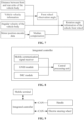
- FIG. 4 is a flowchart of a vehicle control method according to embodiment two of the present application. This embodiment refines the method for acquiring the rotation angle information of the vehicle front wheel based on the preceding embodiment. As shown in FIG. 4 , the method provided by this embodiment includes the steps below.
- the motor position encoder data of the electric steering wheel, vehicle velocity information, the angular velocity of a vehicle body determined according to the IMU data, and the distance between the front and rear axles of the vehicle body are acquired.
- the motor position encoder data of the electric steering wheel includes data such as the current rotation position, rotation angle, and rotation velocity of the electric steering wheel.
- the vehicle velocity information includes the current velocity and direction information of the vehicle.
- the motor position encoder data of the electric steering wheel may be obtained by a motor position encoder. After the vehicle is started, the vehicle velocity information may be determined by the data output in real time by the GNSS module.
- the IMU data may be acquired, and the IMU data includes a vehicle's rotational angular velocity.
- the forward and reverse states of the vehicle may be determined using the mean information of historical IMU data. If the mean information is positive, the vehicle is in the forward state. If the mean information is negative, the vehicle is in the reverse state.
- the vehicle size data may be acquired, and the vehicle size data includes the distance between the front and rear axles of the vehicle body.
- a front wheel observation angle is determined based on the vehicle velocity information, the angular velocity of the vehicle body, and the distance between the front and rear axles of the vehicle body.
- L denotes the distance between the front and rear axles of the vehicle body.
- V gnss denotes the vehicle velocity information.
- ⁇ A denotes the angular velocity of the vehicle body.
- W denotes the front wheel observation angle.
- the front wheel observation angle can be calculated according to the vehicle velocity information, the angular velocity of the vehicle body, and the distance between the front and rear axles of the vehicle body.
- the calculation method is simple, the data required for calculation is easy to obtain, and the accuracy of vehicle automatic driving data can be improved.
- the rotation angle information of the vehicle front wheel is acquired based on the motor position encoder data and the front wheel observation angle.
- the rotation angle information of the vehicle front wheel is acquired based on the motor position encoder data and the front wheel observation angle.
- acquiring the rotation angle information of the vehicle front wheel includes step B1 and step B2.
- step B 1 the angular velocity of the vehicle front wheel is determined based on the motor position encoder data.
- determining the angular velocity of the vehicle front wheel based on the motor position encoder data includes steps B11 to B 13.
- step B 11 dead zone correction is performed on the motor position encoder data based on an imported dead zone value.
- the motor position encoder data includes data such as the current rotation position, rotation angle, and rotation velocity of the electric steering wheel.
- the motor position encoder In the process of generating the preceding data, the motor position encoder generates a control signal dead zone.
- the dead zone correction may be performed on the motor position encoder data based on the dead zone value.
- the dead zone value may be obtained by the import of a terminal device, such as a mobile phone, a tablet, or a notebook computer. By the adjustment of the dead zone value, dead zone correction may be performed on the motor position encoder data.
- step B 12 the position increment of the electric steering wheel is determined according to the corrected motor position encoder data, and an angular velocity of the electric steering wheel is determined according to the position increment and a sampling period.
- the position increment of the electric steering wheel is the positional movement amount of the electric steering wheel at the current moment relative to the previous moment.
- the motor position encoder samples the steering angle of the electric steering wheel at a certain frequency.
- the sampling period is a sampling time interval.
- step B 13 the angular velocity of the vehicle front wheel is determined according to the angular velocity of the electric steering wheel and a preset function relationship between a steering wheel rotation angle and a rotation angle of the vehicle front wheel.
- the method for determining the angular velocity of the vehicle front wheel by the preceding steps may be applied to determine the angular velocity of the front wheel of a wheel-steering tractor to meet the operation requirements of the wheel-steering tractor.
- the rotation angle of the target vehicle front wheel may be determined by using the function relationship between the rotation angle of the electric steering wheel and the rotation angle of the vehicle front wheel.
- the angular velocity of the vehicle front wheel may be determined according to the angular velocity of the electric steering wheel and the function relationship.
- step B2 the rotation angle information of the vehicle front wheel is acquired by using a filter model according to the angular velocity of the vehicle front wheel and the front wheel observation angle.
- the filter model may be a Kalman filter.
- the Kalman filter is an algorithm that may use a linear system state equation to perform optimal estimation of a system state by using the input and output observation data of the system.
- the Kalman filter model may be established according to an angle tracking algorithm. The angular velocity of the vehicle front wheel and the front wheel observation angle are input into the Kalman filter model, and the Kalman filter operation is performed, thereby outputting the rotation angle information of the vehicle front wheel in real time.
- the rotation angle information of the vehicle front wheel is determined, and the Kalman filter model is established, which can output accurate rotation angle information of the vehicle front wheel in real time.
- FIG. 5 is a diagram illustrating the acquisition of rotation angle information of a vehicle front wheel according to embodiment two of the present application, as shown in FIG. 5 .
- a front wheel observation angle is acquired based on the distance between the front and rear axles of the vehicle body, the vehicle velocity information, and the angular velocity of the vehicle body; the dead zone correction is performed on the motor position encoder data; the rotation angle information of the vehicle front wheel is acquired by using a filter model.
- the motor position encoder data of the electric steering wheel, the vehicle velocity information, the angular velocity of the vehicle body determined according to the IMU data, and the distance between the front and rear axles of the vehicle body are acquired; a front wheel observation angle is determined based on the vehicle velocity information, the angular velocity of the vehicle body, and the distance between the front and rear axles of the vehicle body; the rotation angle information of the vehicle front wheel is acquired based on the motor position encoder data and the front wheel observation angle.
- a forward and reverse determination algorithm can be used to distinguish the forward or reverse state of the vehicle.
- the operation requirements of a wheel-steering tractor are met through a method suitable for determining the angular velocity of the front wheels of the wheel-steering tractor.
- the technical solution of this embodiment is easy to promote and use.
- FIG. 6 is a flowchart of a vehicle control method according to embodiment three of the present application. This embodiment refines the method for acquiring the rotation angle information of the vehicle front wheel based on the preceding embodiments. As shown in FIG. 6 , the method of this embodiment includes steps below.
- the motor position encoder data of the electric steering wheel, the vehicle velocity information, the angular velocity of the vehicle body determined according to the IMU data, and the distance between the front and rear axles of the vehicle body are acquired.
- the front wheel observation angle is determined based on the vehicle velocity information, the angular velocity of the vehicle body, and the distance between the front and rear axles of the vehicle body.
- the rotation angle information of the vehicle front wheel is acquired based on the motor position encoder data and the front wheel observation angle.
- acquiring the rotation angle information of the vehicle front wheel based on the motor position encoder data and the front wheel observation angle includes steps C1 and C2.
- step C1 a median value in the motor position encoder data is compensated according to the front wheel observation angle and a present function relationship between a steering wheel rotation angle and a rotation angle of the vehicle front wheel.
- the steering wheel rotation angle corresponding to the front wheel observation angle may be obtained according to the function relationship between the steering wheel rotation angle and the rotation angle of the vehicle front wheel. Then, the steering wheel rotation angle is used to perform median compensation on the motor position encoder data, and it is detected whether a deviation exists between the median value in the motor position encoder data and the steering wheel rotation angle. If a deviation exists, the median value in the motor position encoder data is compensated.
- step C2 the rotation angle information of the vehicle front wheel is acquired based on compensated motor position encoder data and the preset function relationship between the steering wheel rotation angle and the rotation angle of the vehicle front wheel.
- the rotation angle of the vehicle front wheel may be calculated by using the preset function relationship between the rotation angle of the steering wheel and the rotation angle of the vehicle front wheel.
- the rotation angle information of the vehicle front wheel is acquired.
- the rotation angle information of the vehicle front wheel includes the rotation angle of the vehicle front wheel rotates and the rotation direction of the vehicle front wheel rotates.
- the method for determining the rotation angle information of the vehicle front wheel by the preceding steps may be applied to determine the rotation angle information of the front wheels of a rice transplanter to meet the operation requirements of the rice transplanter.
- FIG. 7 is a diagram illustrating the acquisition of rotation angle information of a vehicle front wheel according to embodiment three of the present application, as shown in FIG. 7 .
- a front wheel observation angle is acquired based on the distance between the front and rear axles of the vehicle body, the vehicle velocity information, and the angular velocity of the vehicle body; median compensation is performed on the motor position encoder data; the rotation angle information of the vehicle front wheel is acquired.
- the motor position encoder data of the electric steering wheel, vehicle velocity information, the angular velocity of a vehicle determined according to the IMU data, and the distance between the front and rear axles of the vehicle are acquired; a front wheel observation angle is determined based on the vehicle velocity information, the angular velocity of the vehicle, and the distance between the front and rear axles of the vehicle; the rotation angle information of the vehicle front wheel is acquired based on the motor position encoder data and the front wheel observation angle.
- the operation requirements of the rice transplanter are met through the method suitable for determining the rotation angle information of the front wheels of the rice transplanter.
- the technical solution of this embodiment is easy to promote and use.
- FIG. 8 is a diagram illustrating the structure of an integrated controller according to embodiment four of the present application.
- the integrated controller includes a mobile communication signal receiver, a GNSS module, an IMU module, and a central processing unit.
- the mobile communication signal receiver is configured to receive differential information sent by a base station or a server and send the differential information to a GNSS module.
- the GNSS module is configured to acquire positioning data based on the differential information.
- the IMU module is configured to acquire IMU data.
- the central processing unit is configured to acquire attitude angle data based on the positioning data and the IMU data; acquire rotation angle information of a vehicle front wheel based on the IMU data, motor position encoder data of an electric steering wheel, and vehicle size data; acquire target rotation angle information of the vehicle front wheel based on the positioning data, the attitude angle data, the vehicle size data, the rotation angle information of the vehicle front wheel, and planned path data; and generate target control information based on the target rotation angle information and send the target control information to the electric steering wheel so that the electric steering wheel rotates based on the target control information.
- the central processing unit is configured to acquire the rotation angle information of the vehicle front wheel based on the IMU data, the motor position encoder data of the electric steering wheel, and the vehicle size data in the following manners:
- the motor position encoder data of the electric steering wheel, vehicle velocity information, the angular velocity of a vehicle body determined according to the IMU data, and the distance between the front and rear axles of the vehicle body are acquired;
- a front wheel observation angle is determined based on the vehicle velocity information, the angular velocity of the vehicle body, and the distance between the front and rear axles of the vehicle body;
- the rotation angle information of the vehicle front wheel is acquired based on the motor position encoder data and the front wheel observation angle.
- the central processing unit is configured to acquire the rotation angle information of the vehicle front wheel based on the motor position encoder data and the front wheel observation angle in the following manners: The angular velocity of the vehicle front wheel is determined based on the motor position encoder data; the rotation angle information of the vehicle front wheel is acquired by using a filter model according to the angular velocity of the vehicle front wheel and the front wheel observation angle.
- the central processing unit is configured to determine the angular velocity of the vehicle front wheel based on the motor position encoder data in the following manners: Dead zone correction is performed on the motor position encoder data based on the imported dead zone value; the position increment of the electric steering wheel is determined according to corrected motor position encoder data, and the angular velocity of the electric steering wheel is determined according to the position increment and a sampling period; the angular velocity of the vehicle front wheel is determined according to the angular velocity of the electric steering wheel and a preset function relationship between a steering wheel rotation angle and a rotation angle of the vehicle front wheel.
- the central processing unit is configured to acquire the rotation angle information of the vehicle front wheel based on the motor position encoder data and the front wheel observation angle in the following manner:
- the median value in the motor position encoder data is compensated according to the front wheel observation angle and a present function relationship between a steering wheel rotation angle and a rotation angle of the vehicle front wheel;
- the rotation angle information of the vehicle front wheel is acquired based on compensated motor position encoder data and the preset function relationship between the steering wheel rotation angle and the rotation angle of the vehicle front wheel.
- W denotes the front wheel observation angle.
- L denotes the distance between the front and rear axles of the vehicle body.
- V gnss denotes the vehicle velocity information.
- ⁇ A denotes the angular velocity of the vehicle body.
- the integrated controller may be connected to an independent GNSS antenna to achieve dual-antenna directional attitude measurement.
- the dual antennas may be dual antennas of the GNSS module, and the dual antennas are on one line.
- the directional attitude measurement includes a heading angle and a pitch angle.
- FIG. 9 is a diagram illustrating the structure of an agricultural machinery automatic driving system according to embodiment five of the present application, as shown in FIG. 9 .
- the system includes an integrated controller, a handle, and an electric steering wheel.
- the handle is configured to enable or disable an automatic driving state based on a user operation and/or send planned path data configured by a user to a central processing unit of the integrated controller.
- the electric steering wheel is configured to receive target control information sent by the central processing unit and rotate based on the received target control information to drive a vehicle front wheel to rotate.
- the handle and the electric steering wheel are connected through a controller area network (CAN).
- CAN controller area network
- the system also includes a mobile terminal.
- the mobile terminal is communicatively connected to the integrated controller and configured to perform at least one of path planning, vehicle calibration, parameter setting, parameter adjustment, and enabling or disabling automatic driving in the form of web page access.
- the mobile terminal may be a device such as a mobile phone, a tablet, or a notebook computer.
- the mobile phone is used as an example.
- the agricultural machinery automatic driving system may configure a vehicle parameter, perform mechanical calibration, set a navigation line, and enable or disable automatic driving through the application software or web page on the mobile phone.
- the mobile phone may be connected to the integrated controller in any one manner such as Bluetooth, Wi-Fi, or a mobile network.
- the electric steering wheel includes several parts, that is, a steering drive motor module, a fixed frame module, a clamp module, a sleeve module, and a steering wheel module.
- the fixed frame module may be installed in a fixed position at the bottom of a steering drive motor and fastened to a steering rod through a matching clamp.
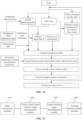
- FIG. 10 is an operation flowchart of an agricultural machinery automatic driving system according to embodiment five of the present application, as shown in FIG. 10 .
- Positioning data output by a GNSS module, IMU data, and motor position encoder data are acquired; attitude angle data is acquired based on the positioning data and the IMU data; the positioning data and attitude angle data are calibrated and corrected based on installation offset calibration data; rotation angle information of a vehicle front wheel is acquired based on the IMU data, vehicle size information, and the motor position encoder data; target control information is generated based on execution mechanism system identification parameters, corrected positioning data and attitude angle data, the vehicle size information, the rotation angle information of the vehicle front wheel, and planned path data to achieve automatic driving of the vehicle.
- the corrected positioning data and attitude angle data, the vehicle size information, the rotation angle information of the vehicle front wheel, and the planned path data are input into a vehicle kinematics model to obtain target rotation angle information of the vehicle front wheel output by the model; a target steering wheel rotation angle is determined based on target steering angle information and the execution mechanism system identification parameters; target control information is generated based on the target steering wheel rotation angle, and the target control information is sent to an electric steering wheel so that the electric steering wheel rotates based on the target control information.
- the preceding products may execute the vehicle control method provided by any embodiment of the present application and have corresponding functional modules and effects of executing the method.
- FIG. 11 is a diagram illustrating the structure of a vehicle control apparatus according to embodiment six of the present application. This embodiment may be applied to the situation of controlling automatic driving of vehicles.
- This apparatus may be implemented in the form of software and/or hardware and may be integrated into any device that provides the function of the vehicle control method.
- the vehicle control apparatus includes a data acquisition module 610, a vehicle front wheel rotation angle determination module 620, a target rotation angle determination module 630, and a steering wheel control module 640.
- the data acquisition module 610 is configured to acquire positioning data output by a global navigation satellite system (GNSS) module and IMU data output by an inertial measurement unit (IMU) module and acquire attitude angle data based on the positioning data and the IMU data.
- the vehicle front wheel rotation angle determination module 620 is configured to acquire rotation angle information of a vehicle front wheel based on the IMU data, motor position encoder data of an electric steering wheel, and vehicle size data.
- the target rotation angle determination module 630 is configured to acquire target rotation angle information of the vehicle front wheel based on the positioning data, the attitude angle data, the vehicle size data, the rotation angle information of the vehicle front wheel, and planned path data.
- the steering wheel control module 640 is configured to generate target control information based on the target rotation angle information and send the target control information to the electric steering wheel so that the electric steering wheel rotates based on the target control information.
- the vehicle front wheel rotation angle determination module 620 includes a first determination unit, a second determination unit, and a vehicle front wheel rotation angle information acquisition unit.
- the first determination unit is configured to acquire the motor position encoder data of the electric steering wheel, vehicle velocity information, the angular velocity of a vehicle body determined according to the IMU data, and the distance between the front and rear axles of the vehicle body.
- the second determination unit is configured to determine a front wheel observation angle based on the vehicle velocity information, the angular velocity of the vehicle body, and the distance between the front and rear axles of the vehicle body.
- the vehicle front wheel rotation angle information acquisition unit is configured to acquire the rotation angle information of the vehicle front wheel based on the motor position encoder data and the front wheel observation angle.
- the vehicle front wheel rotation angle information acquisition unit includes a vehicle front wheel angular velocity subunit and a first rotation angle determination subunit.
- the vehicle front wheel angular velocity subunit is configured to determine the angular velocity of the vehicle front wheel based on the motor position encoder data.
- the first rotation angle determination subunit is configured to acquire the rotation angle information of the vehicle front wheel by using a filter model according to the angular velocity of the vehicle front wheel and the front wheel observation angle.
- the vehicle front wheel angular velocity subunit is configured to perform the following steps: Dead zone correction is performed on the motor position encoder data based on the imported dead zone value; the position increment of the electric steering wheel is determined according to corrected motor position encoder data, and the angular velocity of the electric steering wheel is determined according to the position increment and a sampling period; the angular velocity of the vehicle front wheel is determined according to the angular velocity of the electric steering wheel and a preset function relationship between a steering wheel rotation angle and a rotation angle of the vehicle front wheel.
- the vehicle front wheel rotation angle information acquisition unit includes a median compensation subunit and a second rotation angle determination subunit.
- the median compensation subunit is configured to compensate the median value in the motor position encoder data according to the front wheel observation angle and a present function relationship between a steering wheel rotation angle and a rotation angle of the vehicle front wheel.
- the second rotation angle determination subunit is configured to acquire the rotation angle information of the vehicle front wheel based on compensated motor position encoder data and the preset function relationship between the steering wheel rotation angle and the rotation angle of the vehicle front wheel.
- L denotes the distance between the front and rear axles of the vehicle body.
- V gnss denotes the vehicle velocity information.
- ⁇ A denotes the angular velocity of the vehicle body.
- the steering wheel control module 640 is configured to perform the following steps: A preset function relationship between a steering wheel rotation angle and a rotation angle of the vehicle front wheel is acquired; based on the function relationship, a target steering wheel rotation angle corresponding to the target rotation angle information is determined, and the target control information is generated based on the target steering wheel rotation angle.
- the preceding products may execute the vehicle control method provided by any embodiment of the present application and have corresponding functional modules and effects of executing the method.
- Embodiment seven of the present application provides a computer-readable storage medium.
- the computer-readable storage medium stores a computer program which, when executed by a processor, performs the vehicle control method according to all embodiments of the present application.
- Positioning data output by a global navigation satellite system (GNSS) module and IMU data output by an inertial measurement unit (IMU) module are acquired, and attitude angle data is acquired based on the positioning data and the IMU data; rotation angle information of a vehicle front wheel is acquired based on the IMU data, motor position encoder data of an electric steering wheel, and vehicle size data; target rotation angle information of the vehicle front wheel is acquired based on the positioning data, the attitude angle data, the vehicle size data, the rotation angle information of the vehicle front wheel, and planned path data; target control information is generated based on the target rotation angle information, and the target control information is sent to the electric steering wheel so that the electric steering wheel rotates based on the target control information.
- GNSS global navigation satellite system
- IMU inertial measurement unit
- the computer-readable medium may be a computer-readable signal medium or a computer-readable storage medium.
- the computer-readable storage medium may be, but is not limited to, an electrical, magnetic, optical, electromagnetic, infrared, or semiconductor system, apparatus, or device, or any combination thereof. Examples (a non-exhaustive list) of the computer-readable storage medium include an electrical connection having one or more wires, a portable computer disk, a hard disk, a random-access memory (RAM), a read-only memory (ROM), an erasable programmable read-only memory (EPROM), a flash memory, an optical fiber, a portable compact disc read-only memory (CD-ROM), an optical memory, a magnetic memory, or any suitable combination thereof.
- a computer-readable storage medium may be any tangible medium containing or storing a program that may be used by or in conjunction with an instruction execution system, apparatus, or device.
- the computer-readable signal medium may include a data signal propagated in a baseband or as part of a carrier.
- the data signal carries computer-readable program codes. Such propagated data signals may take a variety of forms, including, but not limited to, electromagnetic signals, optical signals, or any suitable combination thereof.
- the computer-readable signal medium may also be any computer-readable medium other than the computer-readable storage medium.
- the computer-readable medium may send, propagate, or transmit a program used by or used in conjunction with an instruction execution system, apparatus, or device.
- the program code contained on the computer-readable medium may be transmitted on any suitable medium, including, but not limited to, a wireless medium, a wire, an optical cable, a radio frequency (RF), or any suitable combination thereof.
- a wireless medium including, but not limited to, a wireless medium, a wire, an optical cable, a radio frequency (RF), or any suitable combination thereof.
- RF radio frequency
- Computer program codes for performing the operations of the present application may be written in one or more programming languages or combination thereof, including object-oriented programming languages such as Java, Smalltalk, C++, as well as conventional procedural programming languages such as "C" or similar programming languages.
- the program codes may be executed entirely on a user computer, partly on a user computer, as a stand-alone software package, partly on a user computer and partly on a remote computer, or entirely on a remote computer or a server.
- the remote computer may be connected to a user computer via any kind of network including a local area network (LAN) or a wide area network (WAN) or may be connected to an external computer (for example, via the Internet by an Internet service provider).
- LAN local area network
- WAN wide area network
- Internet service provider for example, via the Internet by an Internet service provider
Landscapes
- Engineering & Computer Science (AREA)
- Mechanical Engineering (AREA)
- Transportation (AREA)
- Automation & Control Theory (AREA)
- Combustion & Propulsion (AREA)
- Physics & Mathematics (AREA)
- Mathematical Physics (AREA)
- Chemical & Material Sciences (AREA)
- Human Computer Interaction (AREA)
- Life Sciences & Earth Sciences (AREA)
- Environmental Sciences (AREA)
- Soil Sciences (AREA)
- Steering Control In Accordance With Driving Conditions (AREA)
- Traffic Control Systems (AREA)
- Guiding Agricultural Machines (AREA)
- Transplanting Machines (AREA)
- Navigation (AREA)
- Control Of Driving Devices And Active Controlling Of Vehicle (AREA)
Abstract
Description
- This application claims priority to
Chinese Patent Application No. 202111477499.1 filed with the China National Intellectual Property Administration (CNIPA) on Dec. 6, 2021 - The present application relates to the field of autonomous driving technology, for example, a vehicle control method and apparatus, a controller, a system, and a storage medium.
- As a key technology of precision agriculture, automatic driving of agricultural machinery is widely used in agricultural production processes such as farming, sowing, fertilizing, spraying, and harvesting. Classic key technologies for the automatic driving of agricultural machinery include navigation pose information acquisition, navigation path planning, and navigation control. Accurate and reliable acquisition of the navigation pose information is a prerequisite for the path planning and vehicle body control. An optimized navigation path can effectively reduce resource waste, such as reducing repetitive and missing operations and reducing turning paths at the edge of a field. Fast and stable navigation and control can cope with the complex road environment of farmland to accurately track the navigation path.
- Solutions for automatic driving of agricultural machinery require the installation of a display and an angle sensor in a vehicle, and there are many and complex wiring harnesses that needs to be installed. Due to the complexity of farmland operations, wiring harnesses often get hung up. Moreover, there are many system components, and the cost is relatively high.
- The present application provides a vehicle control method and apparatus, a controller, a system, and a storage medium to achieve rapid and stable control of vehicle driving and reduce cost consumption.
- The present application provides a vehicle control method. The method includes the steps below.
- Positioning data output by a global navigation satellite system (GNSS) module and IMU data output by an inertial measurement unit (IMU) module are acquired, and attitude angle data is acquired based on the positioning data and the IMU data.
- Rotation angle information of a vehicle front wheel is acquired based on the IMU data, motor position encoder data of an electric steering wheel, and vehicle size data.
- Target rotation angle information of the vehicle front wheel is acquired based on the positioning data, the attitude angle data, the vehicle size data, the rotation angle information of the vehicle front wheel, and planned path data.
- Target control information is generated based on the target rotation angle information, and the target control information is sent to the electric steering wheel so that the electric steering wheel rotates based on the target control information.
- The present application further provides an integrated controller. The integrated controller includes a mobile communication signal receiver, an IMU module, and a central processing unit.
- The mobile communication signal receiver is configured to receive differential information sent by a base station or a server and send the differential information to a GNSS module.
- The GNSS module is configured to acquire positioning data based on the differential information.
- The IMU module is configured to acquire IMU data.
- The central processing unit is configured to acquire attitude angle data based on the positioning data and the IMU data; acquire rotation angle information of a vehicle front wheel based on the IMU data, motor position encoder data of an electric steering wheel, and vehicle size data; acquire target rotation angle information of the vehicle front wheel based on the positioning data, the attitude angle data, the vehicle size data, the rotation angle information of the vehicle front wheel, and planned path data; and generate target control information based on the target rotation angle information and send the target control information to the electric steering wheel so that the electric steering wheel rotates based on the target control information.
- The present application further provides an agricultural machinery automatic driving system.
- The system includes the preceding integrated controller, a handle, and an electric steering wheel.
- The handle is configured to perform at least one of the following: enabling or disabling an automatic driving state based on a user operation or sending planned path data configured by a user to a central processing unit of the integrated controller.
- The electric steering wheel is configured to receive target control information sent by the central processing unit and rotate based on the received target control information to drive a vehicle front wheel to rotate.
- The present application further provides a vehicle control apparatus. The apparatus includes a data acquisition module, a vehicle front wheel rotation angle determination module, a target rotation angle determination module, and a steering wheel control module.
- The data acquisition module is configured to acquire positioning data output by a global navigation satellite system (GNSS) module and IMU data output by an inertial measurement unit (IMU) module and acquire attitude angle data based on the positioning data and the IMU data.
- The vehicle front wheel rotation angle determination module is configured to acquire rotation angle information of a vehicle front wheel based on the IMU data, motor position encoder data of an electric steering wheel, and vehicle size data.
- The target rotation angle determination module is configured to acquire target rotation angle information of the vehicle front wheel based on the positioning data, the attitude angle data, the vehicle size data, the rotation angle information of the vehicle front wheel, and planned path data.
- The steering wheel control module is configured to generate target control information based on the target rotation angle information and send the target control information to the electric steering wheel so that the electric steering wheel rotates based on the target control information.
- The present application further provides a computer-readable storage medium storing a computer program. The computer program, when executed by a processor, performs the preceding vehicle control method.
-
-
FIG. 1 is a flowchart of a vehicle control method according to embodiment one of the present application. -
FIG. 2 is a diagram illustrating the calibration of an electric steering wheel according to embodiment one of the present application. -
FIG. 3 is a diagram of buttons of a handle according to embodiment one of the present application. -
FIG. 4 is a flowchart of a vehicle control method according to embodiment two of the present application. -
FIG. 5 is a diagram illustrating the acquisition of rotation angle information of a vehicle front wheel according to embodiment two of the present application. -
FIG. 6 is a flowchart of a vehicle control method according to embodiment three of the present application. -
FIG. 7 is a diagram illustrating the acquisition of rotation angle information of a vehicle front wheel according to embodiment three of the present application. -
FIG. 8 is a diagram illustrating the structure of an integrated controller according to embodiment four of the present application. -
FIG. 9 is a diagram illustrating the structure of an agricultural machinery automatic driving system according to embodiment five of the present application. -
FIG. 10 is an operation flowchart of an agricultural machinery automatic driving system according to embodiment five of the present application. -
FIG. 11 is a diagram illustrating the structure of a vehicle control apparatus according to embodiment six of the present application. - The present application is described below in conjunction with drawings and embodiments. The specific embodiments set forth below are intended to explain the preset application. For ease of description, only parts related to the present application are illustrated in the drawings.
- Similar reference numerals and letters indicate similar items in the following drawings; once a particular item is defined in a drawing, the item does not need to be defined or explained in subsequent drawings. In the description of the present application, terms such as "first" and "second" are only intended to distinguish the description and are not to be construed as indicating or implying relative importance.
-
FIG. 1 is a flowchart of a vehicle control method according to embodiment one of the present application. This embodiment may be applied to the situation of controlling automatic driving of vehicles. The method may be executed by a vehicle control apparatus in the embodiment of the present application. The apparatus may be implemented in software and/or hardware. As shown inFIG. 1 , the method includes the steps below. - In S110, positioning data output by a global navigation satellite system (GNSS) module and IMU data output by an inertial measurement unit (IMU) module are acquired, and attitude angle data is acquired based on the positioning data and the IMU data.
- GNSS generally refers to all satellite navigation systems, which have omnipotent, global, all-weather, continuous, and real-time navigation, positioning, and timing functions. In the embodiment of the present application, the GNSS module supports both GNSS positioning and GNSS orientation. GNSS orientation may determine the direction of the geometric vector formed by two points in space in a given coordinate system. The positioning data output by GNSS may be received using a GNSS receiving antenna. The positioning data includes location positioning information and orientation information. The GNSS module also supports enhanced modes such as real-time kinematic (RTK) positioning, satellite-based augmentation system (SBAS), differential global positioning system (DGPS), and Precise Point Positioning (PPP) technology. IMU may be configured to detect and measure acceleration and a rotational motion state. In the embodiment of the present application, IMU may collect and output IMU data, and the IMU data includes a rotational angular velocity of a vehicle body and an acceleration of the vehicle body. The attitude angle data is calculated based on the GNSS positioning data and the IMU data. The attitude angle data includes a heading angle, a pitch angle, and a roll angle. Generally, the spatial rotation of the body coordinate system relative to the geographic coordinate system may be expressed in the order of the heading angle, the pitch angle, and the roll angle.
- In S120, rotation angle information of a vehicle front wheel is acquired based on the IMU data, motor position encoder data of an electric steering wheel, and vehicle size data.
- The motor position encoder data of the electric steering wheel represents the current rotation position of the electric steering wheel. The vehicle size data includes the distance between the front and rear axles of a vehicle body, the height of a rear axle, front track, the distance from an antenna to a central axis, the position of the antenna relative to the central axis, the distance from the antenna to the rear axle, the position of the antenna relative to the rear axle, the height of the antenna, and the operation width. The vehicle size data may be used to build vehicle kinematics models and perform data corrections.
- Vehicle size information may be entered by using a terminal device such as a mobile phone or a tablet, and the electric steering wheel is calibrated.
FIG. 2 is a diagram illustrating the calibration of an electric steering wheel according to embodiment one of the present application, as shown inFIG. 2 . The process of calibrating the electric steering wheel is described in steps 1 to 6. The calibration process requires an open, flat, and hard ground approximately 100 meters long and 10 meters wide. InFIG. 2 , two circles represent the vehicle's driving path; "540 degrees" means that the electric steering wheel is rotated to enable the vehicle to rotate 540 degrees; "10 meters" means that after rotating 540 degrees, the vehicle drives forward 10 meters. - In step 1, a line AB is configured. The distance between two points A and B should be greater than 70 meters.
- In step 2, after the line AB is configured, the vehicle is manually turned around and parked at point B with the front of the vehicle facing point A.
- In step 3, the vehicle keeps driving forward at a constant speed of 2 Km/h and drives automatically to point A.
- In step 4, the vehicle is manually turned around and parked at point A with the front of the vehicle facing point B.
- In step 5, the vehicle keeps driving forward at a constant speed of 2 Km/h and drives automatically to point B.
- In step 6, calibration is completed.
FIG. 3 is a diagram of buttons of a handle according to embodiment one of the present application. As shown inFIG. 3 , the handle includes at least three buttons. During the practical operation, the AUTO button controls whether to enable or disable the automatic driving state. Buttons "A" and "B" on the handle control the linear path planning operation of points A and B. After the electric steering wheel is calibrated, installation offset calibration may be performed on a terminal device. The installation offset calibration can eliminate related installation errors. Performing calibration on the electric steering wheel via the preceding steps may establish execution mechanism system identification, that is, a function relationship between a steering wheel rotation angle and a rotation angle of the vehicle front wheel may be established. - The rotation angle information of the vehicle front wheel is acquired based on the IMU data, the motor position encoder data of the electric steering wheel, and the vehicle size data. The vehicle front wheel angle information refers to information such as the current vehicle front wheel rotation angle and rotation angle direction.
- In S130, target rotation angle information of the vehicle front wheel is acquired based on the positioning data, the attitude angle data, the vehicle size data, the rotation angle information of the vehicle front wheel, and planned path data.
- The planned path data may be obtained in the form of web page access by WIFI, Bluetooth, or a mobile communication data link. The planned path data may be imported via a mobile phone or obtained by a user operating the buttons of the handle. The positioning data, the attitude angle data, the vehicle size data, the rotation angle information of the vehicle front wheel, and the planned path data are input into a vehicle kinematics model to acquire the target rotation angle information of the vehicle front wheel output by the model. The target rotation angle information of the vehicle front wheel includes the angle information and direction information at which the vehicle's front wheels should rotate at the next moment.
- In S140, target control information is generated based on the target rotation angle information, and the target control information is sent to the electric steering wheel so that the electric steering wheel rotates based on the target control information.
- The target rotation angle information is the angle information at which the front wheels of the vehicle controlled by the steering wheel should rotate. The target control information may be generated according to the target rotation angle information. In this solution embodiment, in an embodiment, generating the target control information based on the target rotation angle information includes steps A1 and A2.
- In step A1, a preset function relationship between a steering wheel rotation angle and a rotation angle of the vehicle front wheel is acquired.
- By the rotation of the electric steering wheel, the vehicle's front wheels may be controlled to rotate. A function relationship exists between the rotation angle of the electric steering wheel and the rotation angle of the front wheel. The function relationship may be acquired via the preceding calibration process of the electric steering wheel. If the rotation angle of the electric steering wheel is known, the rotation angle of the vehicle front wheel may be obtained. If the rotation angle of the vehicle front wheel is known, the rotation angle of the electric steering wheel may be obtained.
- In step A2, based on the function relationship, a target steering wheel rotation angle corresponding to the target rotation angle information is determined, and the target control information is generated based on the target steering wheel rotation angle.
- The target rotation angle information includes the angle information at which the vehicle's front wheels should rotate and the direction information at which the vehicle's front wheels should rotate. The target steering wheel rotation angle is the angle at which the electric steering wheel should rotate. As described in step A1, after the information about the angle at which the front wheels of the vehicle should rotate is learned, the rotation angle of the electric steering wheel, that is, the target steering wheel rotation angle may be obtained based on the preset function relationship. The target control information includes the target steering wheel rotation angle. After the target steering wheel rotation angle is obtained, target control information is generated to control the electric steering wheel to rotate based on the target control information.
- Via the preceding steps, the electric steering wheel rotates based on the target control information, and the vehicle can be accurately and rapidly controlled to drive according to the path planning information, achieving automatic driving of the vehicle.
- In the technical solution of this embodiment, positioning data output by a global navigation satellite system (GNSS) module and IMU data output by an inertial measurement unit (IMU) module are acquired, and attitude angle data is acquired based on the positioning data and the IMU data; rotation angle information of a vehicle front wheel is acquired based on the IMU data, motor position encoder data of an electric steering wheel, and vehicle size data; target rotation angle information of the vehicle front wheel is acquired based on the positioning data, the attitude angle data, the vehicle size data, the rotation angle information of the vehicle front wheel, and planned path data; target control information is generated based on the target rotation angle information, and the target control information is sent to the electric steering wheel so that the electric steering wheel rotates based on the target control information. In the technical solution of this embodiment, GNSS positioning data accurate to a centimeter level can be acquired; via a mobile terminal, vehicle parameters can be configured, calibration can be performed, and path planning data can be designed; after the configuration, the vehicle can be driven automatically detached from the terminal. Moreover, fixed-point navigation line control and enabling and disabling of the automatic driving function can be achieved through the buttons of the handle. In this manner, it is easy to installation and maintenance hardware facilities, which greatly reduces consumption costs and reduces the hardware damage rate of the automatic driving system. Additionally, the driving state of the vehicle can be quickly and stably controlled. In the embodiment of the present application, accurate and reliable navigation pose information can be acquired. When the environment and road conditions are complex, the driving state of the vehicle can be quickly and stably controlled. Traditional displays and angle sensors do not need to be used. Thus, it is easy to install and maintain hardware facilities, which greatly reduces costs.
-
FIG. 4 is a flowchart of a vehicle control method according to embodiment two of the present application. This embodiment refines the method for acquiring the rotation angle information of the vehicle front wheel based on the preceding embodiment. As shown inFIG. 4 , the method provided by this embodiment includes the steps below. - In S210, the motor position encoder data of the electric steering wheel, vehicle velocity information, the angular velocity of a vehicle body determined according to the IMU data, and the distance between the front and rear axles of the vehicle body are acquired.
- The motor position encoder data of the electric steering wheel includes data such as the current rotation position, rotation angle, and rotation velocity of the electric steering wheel. The vehicle velocity information includes the current velocity and direction information of the vehicle. The motor position encoder data of the electric steering wheel may be obtained by a motor position encoder. After the vehicle is started, the vehicle velocity information may be determined by the data output in real time by the GNSS module. In S110, the IMU data may be acquired, and the IMU data includes a vehicle's rotational angular velocity. When the vehicle velocity increases to a preset threshold, the forward and reverse states of the vehicle may be determined using the mean information of historical IMU data. If the mean information is positive, the vehicle is in the forward state. If the mean information is negative, the vehicle is in the reverse state. In
S 120, the vehicle size data may be acquired, and the vehicle size data includes the distance between the front and rear axles of the vehicle body. - In S220, a front wheel observation angle is determined based on the vehicle velocity information, the angular velocity of the vehicle body, and the distance between the front and rear axles of the vehicle body.
- In this solution embodiment, in an embodiment, the front wheel observation angle may be determined based on the vehicle velocity information, the angular velocity of the vehicle body, and the distance between the front and rear axles of the vehicle body by using the following formula:

- L denotes the distance between the front and rear axles of the vehicle body. Vgnss denotes the vehicle velocity information. ϕ A denotes the angular velocity of the vehicle body. W denotes the front wheel observation angle.
- The front wheel observation angle can be calculated according to the vehicle velocity information, the angular velocity of the vehicle body, and the distance between the front and rear axles of the vehicle body. The calculation method is simple, the data required for calculation is easy to obtain, and the accuracy of vehicle automatic driving data can be improved.
- In S230, the rotation angle information of the vehicle front wheel is acquired based on the motor position encoder data and the front wheel observation angle.
- After the front wheel observation angle is calculated, the rotation angle information of the vehicle front wheel is acquired based on the motor position encoder data and the front wheel observation angle. In this solution embodiment, in an embodiment, acquiring the rotation angle information of the vehicle front wheel includes step B1 and step B2.
- In step B 1, the angular velocity of the vehicle front wheel is determined based on the motor position encoder data.
- In this solution embodiment, in an embodiment, determining the angular velocity of the vehicle front wheel based on the motor position encoder data includes steps B11 to B 13.
- In step B 11, dead zone correction is performed on the motor position encoder data based on an imported dead zone value.
- The motor position encoder data includes data such as the current rotation position, rotation angle, and rotation velocity of the electric steering wheel. In the process of generating the preceding data, the motor position encoder generates a control signal dead zone. The dead zone correction may be performed on the motor position encoder data based on the dead zone value. The dead zone value may be obtained by the import of a terminal device, such as a mobile phone, a tablet, or a notebook computer. By the adjustment of the dead zone value, dead zone correction may be performed on the motor position encoder data.
- In step B 12, the position increment of the electric steering wheel is determined according to the corrected motor position encoder data, and an angular velocity of the electric steering wheel is determined according to the position increment and a sampling period.
- The position increment of the electric steering wheel is the positional movement amount of the electric steering wheel at the current moment relative to the previous moment. The motor position encoder samples the steering angle of the electric steering wheel at a certain frequency. The sampling period is a sampling time interval. The angular velocity of the electric steering wheel may be determined according to the position increment and the sampling period. For example, the position increment of the electric steering wheel is S, the sampling period is t, and then the angular velocity = S/t.
- In step B 13, the angular velocity of the vehicle front wheel is determined according to the angular velocity of the electric steering wheel and a preset function relationship between a steering wheel rotation angle and a rotation angle of the vehicle front wheel.
- The method for determining the angular velocity of the vehicle front wheel by the preceding steps may be applied to determine the angular velocity of the front wheel of a wheel-steering tractor to meet the operation requirements of the wheel-steering tractor.
- As described in S 140, the rotation angle of the target vehicle front wheel may be determined by using the function relationship between the rotation angle of the electric steering wheel and the rotation angle of the vehicle front wheel. The angular velocity of the vehicle front wheel may be determined according to the angular velocity of the electric steering wheel and the function relationship.
- In step B2, the rotation angle information of the vehicle front wheel is acquired by using a filter model according to the angular velocity of the vehicle front wheel and the front wheel observation angle.
- The filter model may be a Kalman filter. The Kalman filter is an algorithm that may use a linear system state equation to perform optimal estimation of a system state by using the input and output observation data of the system. In this solution embodiment, the Kalman filter model may be established according to an angle tracking algorithm. The angular velocity of the vehicle front wheel and the front wheel observation angle are input into the Kalman filter model, and the Kalman filter operation is performed, thereby outputting the rotation angle information of the vehicle front wheel in real time.
- Through the preceding steps, the rotation angle information of the vehicle front wheel is determined, and the Kalman filter model is established, which can output accurate rotation angle information of the vehicle front wheel in real time.
-
FIG. 5 is a diagram illustrating the acquisition of rotation angle information of a vehicle front wheel according to embodiment two of the present application, as shown inFIG. 5 . A front wheel observation angle is acquired based on the distance between the front and rear axles of the vehicle body, the vehicle velocity information, and the angular velocity of the vehicle body; the dead zone correction is performed on the motor position encoder data; the rotation angle information of the vehicle front wheel is acquired by using a filter model. - In the technical solution of this embodiment, the motor position encoder data of the electric steering wheel, the vehicle velocity information, the angular velocity of the vehicle body determined according to the IMU data, and the distance between the front and rear axles of the vehicle body are acquired; a front wheel observation angle is determined based on the vehicle velocity information, the angular velocity of the vehicle body, and the distance between the front and rear axles of the vehicle body; the rotation angle information of the vehicle front wheel is acquired based on the motor position encoder data and the front wheel observation angle. A forward and reverse determination algorithm can be used to distinguish the forward or reverse state of the vehicle. The operation requirements of a wheel-steering tractor are met through a method suitable for determining the angular velocity of the front wheels of the wheel-steering tractor. Thus, the technical solution of this embodiment is easy to promote and use.
-
FIG. 6 is a flowchart of a vehicle control method according to embodiment three of the present application. This embodiment refines the method for acquiring the rotation angle information of the vehicle front wheel based on the preceding embodiments. As shown inFIG. 6 , the method of this embodiment includes steps below. - In S310, the motor position encoder data of the electric steering wheel, the vehicle velocity information, the angular velocity of the vehicle body determined according to the IMU data, and the distance between the front and rear axles of the vehicle body are acquired.
- In S320, the front wheel observation angle is determined based on the vehicle velocity information, the angular velocity of the vehicle body, and the distance between the front and rear axles of the vehicle body.
- In S330, the rotation angle information of the vehicle front wheel is acquired based on the motor position encoder data and the front wheel observation angle.
- In this solution embodiment, in an embodiment, acquiring the rotation angle information of the vehicle front wheel based on the motor position encoder data and the front wheel observation angle includes steps C1 and C2.
- In step C1, a median value in the motor position encoder data is compensated according to the front wheel observation angle and a present function relationship between a steering wheel rotation angle and a rotation angle of the vehicle front wheel.
- First, the steering wheel rotation angle corresponding to the front wheel observation angle may be obtained according to the function relationship between the steering wheel rotation angle and the rotation angle of the vehicle front wheel. Then, the steering wheel rotation angle is used to perform median compensation on the motor position encoder data, and it is detected whether a deviation exists between the median value in the motor position encoder data and the steering wheel rotation angle. If a deviation exists, the median value in the motor position encoder data is compensated.
- In step C2, the rotation angle information of the vehicle front wheel is acquired based on compensated motor position encoder data and the preset function relationship between the steering wheel rotation angle and the rotation angle of the vehicle front wheel.
- The rotation angle of the vehicle front wheel may be calculated by using the preset function relationship between the rotation angle of the steering wheel and the rotation angle of the vehicle front wheel. The rotation angle information of the vehicle front wheel is acquired. The rotation angle information of the vehicle front wheel includes the rotation angle of the vehicle front wheel rotates and the rotation direction of the vehicle front wheel rotates.
- The method for determining the rotation angle information of the vehicle front wheel by the preceding steps may be applied to determine the rotation angle information of the front wheels of a rice transplanter to meet the operation requirements of the rice transplanter.
-
FIG. 7 is a diagram illustrating the acquisition of rotation angle information of a vehicle front wheel according to embodiment three of the present application, as shown inFIG. 7 . A front wheel observation angle is acquired based on the distance between the front and rear axles of the vehicle body, the vehicle velocity information, and the angular velocity of the vehicle body; median compensation is performed on the motor position encoder data; the rotation angle information of the vehicle front wheel is acquired. - In the technical solution of this embodiment, the motor position encoder data of the electric steering wheel, vehicle velocity information, the angular velocity of a vehicle determined according to the IMU data, and the distance between the front and rear axles of the vehicle are acquired; a front wheel observation angle is determined based on the vehicle velocity information, the angular velocity of the vehicle, and the distance between the front and rear axles of the vehicle; the rotation angle information of the vehicle front wheel is acquired based on the motor position encoder data and the front wheel observation angle. The operation requirements of the rice transplanter are met through the method suitable for determining the rotation angle information of the front wheels of the rice transplanter. Thus, the technical solution of this embodiment is easy to promote and use.
-
FIG. 8 is a diagram illustrating the structure of an integrated controller according to embodiment four of the present application. As shown inFIG. 8 , the integrated controller includes a mobile communication signal receiver, a GNSS module, an IMU module, and a central processing unit. - The mobile communication signal receiver is configured to receive differential information sent by a base station or a server and send the differential information to a GNSS module. The GNSS module is configured to acquire positioning data based on the differential information. The IMU module is configured to acquire IMU data. The central processing unit is configured to acquire attitude angle data based on the positioning data and the IMU data; acquire rotation angle information of a vehicle front wheel based on the IMU data, motor position encoder data of an electric steering wheel, and vehicle size data; acquire target rotation angle information of the vehicle front wheel based on the positioning data, the attitude angle data, the vehicle size data, the rotation angle information of the vehicle front wheel, and planned path data; and generate target control information based on the target rotation angle information and send the target control information to the electric steering wheel so that the electric steering wheel rotates based on the target control information.
- In an embodiment, the central processing unit is configured to acquire the rotation angle information of the vehicle front wheel based on the IMU data, the motor position encoder data of the electric steering wheel, and the vehicle size data in the following manners:
The motor position encoder data of the electric steering wheel, vehicle velocity information, the angular velocity of a vehicle body determined according to the IMU data, and the distance between the front and rear axles of the vehicle body are acquired; a front wheel observation angle is determined based on the vehicle velocity information, the angular velocity of the vehicle body, and the distance between the front and rear axles of the vehicle body; the rotation angle information of the vehicle front wheel is acquired based on the motor position encoder data and the front wheel observation angle. - The central processing unit is configured to acquire the rotation angle information of the vehicle front wheel based on the motor position encoder data and the front wheel observation angle in the following manners:
The angular velocity of the vehicle front wheel is determined based on the motor position encoder data; the rotation angle information of the vehicle front wheel is acquired by using a filter model according to the angular velocity of the vehicle front wheel and the front wheel observation angle. - The central processing unit is configured to determine the angular velocity of the vehicle front wheel based on the motor position encoder data in the following manners:
Dead zone correction is performed on the motor position encoder data based on the imported dead zone value; the position increment of the electric steering wheel is determined according to corrected motor position encoder data, and the angular velocity of the electric steering wheel is determined according to the position increment and a sampling period; the angular velocity of the vehicle front wheel is determined according to the angular velocity of the electric steering wheel and a preset function relationship between a steering wheel rotation angle and a rotation angle of the vehicle front wheel. - In an embodiment, the central processing unit is configured to acquire the rotation angle information of the vehicle front wheel based on the motor position encoder data and the front wheel observation angle in the following manner:
The median value in the motor position encoder data is compensated according to the front wheel observation angle and a present function relationship between a steering wheel rotation angle and a rotation angle of the vehicle front wheel; the rotation angle information of the vehicle front wheel is acquired based on compensated motor position encoder data and the preset function relationship between the steering wheel rotation angle and the rotation angle of the vehicle front wheel. - The central processing unit is configured to determine the front wheel observation angle by using the following formula:

- The integrated controller may be connected to an independent GNSS antenna to achieve dual-antenna directional attitude measurement. The dual antennas may be dual antennas of the GNSS module, and the dual antennas are on one line. The directional attitude measurement includes a heading angle and a pitch angle.
-
FIG. 9 is a diagram illustrating the structure of an agricultural machinery automatic driving system according to embodiment five of the present application, as shown inFIG. 9 . The system includes an integrated controller, a handle, and an electric steering wheel. - The handle is configured to enable or disable an automatic driving state based on a user operation and/or send planned path data configured by a user to a central processing unit of the integrated controller. The electric steering wheel is configured to receive target control information sent by the central processing unit and rotate based on the received target control information to drive a vehicle front wheel to rotate. The handle and the electric steering wheel are connected through a controller area network (CAN).
- In an embodiment, the system also includes a mobile terminal.
- The mobile terminal is communicatively connected to the integrated controller and configured to perform at least one of path planning, vehicle calibration, parameter setting, parameter adjustment, and enabling or disabling automatic driving in the form of web page access.
- The mobile terminal may be a device such as a mobile phone, a tablet, or a notebook computer. The mobile phone is used as an example. The agricultural machinery automatic driving system may configure a vehicle parameter, perform mechanical calibration, set a navigation line, and enable or disable automatic driving through the application software or web page on the mobile phone. The mobile phone may be connected to the integrated controller in any one manner such as Bluetooth, Wi-Fi, or a mobile network.
- The electric steering wheel includes several parts, that is, a steering drive motor module, a fixed frame module, a clamp module, a sleeve module, and a steering wheel module. The fixed frame module may be installed in a fixed position at the bottom of a steering drive motor and fastened to a steering rod through a matching clamp.
-
FIG. 10 is an operation flowchart of an agricultural machinery automatic driving system according to embodiment five of the present application, as shown inFIG. 10 . Positioning data output by a GNSS module, IMU data, and motor position encoder data are acquired; attitude angle data is acquired based on the positioning data and the IMU data; the positioning data and attitude angle data are calibrated and corrected based on installation offset calibration data; rotation angle information of a vehicle front wheel is acquired based on the IMU data, vehicle size information, and the motor position encoder data; target control information is generated based on execution mechanism system identification parameters, corrected positioning data and attitude angle data, the vehicle size information, the rotation angle information of the vehicle front wheel, and planned path data to achieve automatic driving of the vehicle. The corrected positioning data and attitude angle data, the vehicle size information, the rotation angle information of the vehicle front wheel, and the planned path data are input into a vehicle kinematics model to obtain target rotation angle information of the vehicle front wheel output by the model; a target steering wheel rotation angle is determined based on target steering angle information and the execution mechanism system identification parameters; target control information is generated based on the target steering wheel rotation angle, and the target control information is sent to an electric steering wheel so that the electric steering wheel rotates based on the target control information. The preceding products may execute the vehicle control method provided by any embodiment of the present application and have corresponding functional modules and effects of executing the method. -
FIG. 11 is a diagram illustrating the structure of a vehicle control apparatus according to embodiment six of the present application. This embodiment may be applied to the situation of controlling automatic driving of vehicles. This apparatus may be implemented in the form of software and/or hardware and may be integrated into any device that provides the function of the vehicle control method. As shown inFIG. 11 , the vehicle control apparatus includes adata acquisition module 610, a vehicle front wheel rotationangle determination module 620, a target rotationangle determination module 630, and a steeringwheel control module 640. - The
data acquisition module 610 is configured to acquire positioning data output by a global navigation satellite system (GNSS) module and IMU data output by an inertial measurement unit (IMU) module and acquire attitude angle data based on the positioning data and the IMU data. The vehicle front wheel rotationangle determination module 620 is configured to acquire rotation angle information of a vehicle front wheel based on the IMU data, motor position encoder data of an electric steering wheel, and vehicle size data. The target rotationangle determination module 630 is configured to acquire target rotation angle information of the vehicle front wheel based on the positioning data, the attitude angle data, the vehicle size data, the rotation angle information of the vehicle front wheel, and planned path data. The steeringwheel control module 640 is configured to generate target control information based on the target rotation angle information and send the target control information to the electric steering wheel so that the electric steering wheel rotates based on the target control information. - In an embodiment, the vehicle front wheel rotation
angle determination module 620 includes a first determination unit, a second determination unit, and a vehicle front wheel rotation angle information acquisition unit. - The first determination unit is configured to acquire the motor position encoder data of the electric steering wheel, vehicle velocity information, the angular velocity of a vehicle body determined according to the IMU data, and the distance between the front and rear axles of the vehicle body. The second determination unit is configured to determine a front wheel observation angle based on the vehicle velocity information, the angular velocity of the vehicle body, and the distance between the front and rear axles of the vehicle body. The vehicle front wheel rotation angle information acquisition unit is configured to acquire the rotation angle information of the vehicle front wheel based on the motor position encoder data and the front wheel observation angle.
- In an embodiment, the vehicle front wheel rotation angle information acquisition unit includes a vehicle front wheel angular velocity subunit and a first rotation angle determination subunit.
- The vehicle front wheel angular velocity subunit is configured to determine the angular velocity of the vehicle front wheel based on the motor position encoder data. The first rotation angle determination subunit is configured to acquire the rotation angle information of the vehicle front wheel by using a filter model according to the angular velocity of the vehicle front wheel and the front wheel observation angle.
- In an embodiment, the vehicle front wheel angular velocity subunit is configured to perform the following steps:
Dead zone correction is performed on the motor position encoder data based on the imported dead zone value; the position increment of the electric steering wheel is determined according to corrected motor position encoder data, and the angular velocity of the electric steering wheel is determined according to the position increment and a sampling period; the angular velocity of the vehicle front wheel is determined according to the angular velocity of the electric steering wheel and a preset function relationship between a steering wheel rotation angle and a rotation angle of the vehicle front wheel. - In an embodiment, the vehicle front wheel rotation angle information acquisition unit includes a median compensation subunit and a second rotation angle determination subunit.
- The median compensation subunit is configured to compensate the median value in the motor position encoder data according to the front wheel observation angle and a present function relationship between a steering wheel rotation angle and a rotation angle of the vehicle front wheel. The second rotation angle determination subunit is configured to acquire the rotation angle information of the vehicle front wheel based on compensated motor position encoder data and the preset function relationship between the steering wheel rotation angle and the rotation angle of the vehicle front wheel.
- The second determination unit is configured to determine the front wheel observation angle by using the following formula:

- In an embodiment, the steering
wheel control module 640 is configured to perform the following steps:
A preset function relationship between a steering wheel rotation angle and a rotation angle of the vehicle front wheel is acquired; based on the function relationship, a target steering wheel rotation angle corresponding to the target rotation angle information is determined, and the target control information is generated based on the target steering wheel rotation angle. - The preceding products may execute the vehicle control method provided by any embodiment of the present application and have corresponding functional modules and effects of executing the method.
- Embodiment seven of the present application provides a computer-readable storage medium. The computer-readable storage medium stores a computer program which, when executed by a processor, performs the vehicle control method according to all embodiments of the present application. Positioning data output by a global navigation satellite system (GNSS) module and IMU data output by an inertial measurement unit (IMU) module are acquired, and attitude angle data is acquired based on the positioning data and the IMU data; rotation angle information of a vehicle front wheel is acquired based on the IMU data, motor position encoder data of an electric steering wheel, and vehicle size data; target rotation angle information of the vehicle front wheel is acquired based on the positioning data, the attitude angle data, the vehicle size data, the rotation angle information of the vehicle front wheel, and planned path data; target control information is generated based on the target rotation angle information, and the target control information is sent to the electric steering wheel so that the electric steering wheel rotates based on the target control information.
- Any combination of one or more computer-readable media may be adopted. The computer-readable medium may be a computer-readable signal medium or a computer-readable storage medium. The computer-readable storage medium may be, but is not limited to, an electrical, magnetic, optical, electromagnetic, infrared, or semiconductor system, apparatus, or device, or any combination thereof. Examples (a non-exhaustive list) of the computer-readable storage medium include an electrical connection having one or more wires, a portable computer disk, a hard disk, a random-access memory (RAM), a read-only memory (ROM), an erasable programmable read-only memory (EPROM), a flash memory, an optical fiber, a portable compact disc read-only memory (CD-ROM), an optical memory, a magnetic memory, or any suitable combination thereof. In the document, a computer-readable storage medium may be any tangible medium containing or storing a program that may be used by or in conjunction with an instruction execution system, apparatus, or device.
- The computer-readable signal medium may include a data signal propagated in a baseband or as part of a carrier. The data signal carries computer-readable program codes. Such propagated data signals may take a variety of forms, including, but not limited to, electromagnetic signals, optical signals, or any suitable combination thereof. The computer-readable signal medium may also be any computer-readable medium other than the computer-readable storage medium. The computer-readable medium may send, propagate, or transmit a program used by or used in conjunction with an instruction execution system, apparatus, or device.
- The program code contained on the computer-readable medium may be transmitted on any suitable medium, including, but not limited to, a wireless medium, a wire, an optical cable, a radio frequency (RF), or any suitable combination thereof.
- Computer program codes for performing the operations of the present application may be written in one or more programming languages or combination thereof, including object-oriented programming languages such as Java, Smalltalk, C++, as well as conventional procedural programming languages such as "C" or similar programming languages. The program codes may be executed entirely on a user computer, partly on a user computer, as a stand-alone software package, partly on a user computer and partly on a remote computer, or entirely on a remote computer or a server. In the case relating to a remote computer, the remote computer may be connected to a user computer via any kind of network including a local area network (LAN) or a wide area network (WAN) or may be connected to an external computer (for example, via the Internet by an Internet service provider).
Claims (17)
- A vehicle control method, comprising:acquiring positioning data output by a global navigation satellite system, GNSS, module and IMU data output by an inertial measurement unit, IMU, module, and acquiring attitude angle data based on the positioning data and the IMU data;acquiring rotation angle information of a vehicle front wheel based on the IMU data, motor position encoder data of an electric steering wheel, and vehicle size data;acquiring target rotation angle information of the vehicle front wheel based on the positioning data, the attitude angle data, the vehicle size data, the rotation angle information of the vehicle front wheel, and planned path data; andgenerating target control information based on the target rotation angle information, and sending the target control information to the electric steering wheel so that the electric steering wheel rotates based on the target control information.
- The method of claim 1, wherein acquiring the rotation angle information of the vehicle front wheel based on the IMU data, the motor position encoder data of the electric steering wheel, and the vehicle size data comprises:acquiring the motor position encoder data of the electric steering wheel, vehicle velocity information, an angular velocity of a vehicle body determined according to the IMU data, and a distance between front and rear axles of the vehicle body in the vehicle size data;determining a front wheel observation angle based on the vehicle velocity information, the angular velocity of the vehicle body, and the distance between the front and rear axles of the vehicle body; andacquiring the rotation angle information of the vehicle front wheel based on the motor position encoder data and the front wheel observation angle.
- The method of claim 2, wherein acquiring the rotation angle information of the vehicle front wheel based on the motor position encoder data and the front wheel observation angle comprises:determining an angular velocity of the vehicle front wheel based on the motor position encoder data; andacquiring, by using a filter model, the rotation angle information of the vehicle front wheel according to the angular velocity of the vehicle front wheel and the front wheel observation angle.
- The method of claim 3, wherein determining the angular velocity of the vehicle front wheel based on the motor position encoder data comprises:performing dead zone correction on the motor position encoder data based on an imported dead zone value;determining a position increment of the electric steering wheel according to corrected motor position encoder data, and determining an angular velocity of the electric steering wheel according to the position increment and a sampling period; anddetermining the angular velocity of the vehicle front wheel according to the angular velocity of the electric steering wheel and a preset function relationship between a steering wheel rotation angle and a rotation angle of the vehicle front wheel.
- The method of claim 2, wherein acquiring the rotation angle information of the vehicle front wheel based on the motor position encoder data and the front wheel observation angle comprises:compensating a median value in the motor position encoder data according to the front wheel observation angle and a preset function relationship between a steering wheel rotation angle and a rotation angle of the vehicle front wheel; andacquiring the rotation angle information of the vehicle front wheel based on compensated motor position encoder data and the preset function relationship between the steering wheel rotation angle and the rotation angle of the vehicle front wheel.
- The method of claim 2, wherein the front wheel observation angle is determined by using a following formula:

- The method of claim 1, wherein generating the target control information based on the target rotation angle information comprises:acquiring a preset function relationship between a steering wheel rotation angle and a rotation angle of the vehicle front wheel; anddetermining, based on the function relationship, a target steering wheel rotation angle corresponding to the target rotation angle information, and generating the target control information based on the target steering wheel rotation angle.
- An integrated controller, comprising:a mobile communication signal receiver, which is configured to receive differential information sent by a base station or a server and send the differential information to a global navigation satellite system, GNSS, module;the GNSS module, which is configured to acquire positioning data based on the differential information;an inertial measurement unit, IMU, module, which is configured to acquire IMU data; anda central processing unit, which is configured to acquire attitude angle data based on the positioning data and the IMU data; acquire rotation angle information of a vehicle front wheel based on the IMU data, motor position encoder data of an electric steering wheel, and vehicle size data; acquire target rotation angle information of the vehicle front wheel based on the positioning data, the attitude angle data, the vehicle size data, the rotation angle information of the vehicle front wheel, and planned path data; and generate target control information based on the target rotation angle information and send the target control information to the electric steering wheel so that the electric steering wheel rotates based on the target control information.
- The controller of claim 8, wherein the central processing unit is configured to acquire the rotation angle information of the vehicle front wheel based on the IMU data, the motor position encoder data of the electric steering wheel, and the vehicle size data in the following manners:acquiring the motor position encoder data of the electric steering wheel, vehicle velocity information, an angular velocity of a vehicle body determined according to the IMU data, and a distance between front and rear axles of the vehicle body in the vehicle size data;determining a front wheel observation angle based on the vehicle velocity information, the angular velocity of the vehicle body, and the distance between the front and rear axles of the vehicle body; andacquiring the rotation angle information of the vehicle front wheel based on the motor position encoder data and the front wheel observation angle.
- The controller of claim 9, wherein the central processing unit is configured to acquire the rotation angle information of the vehicle front wheel based on the motor position encoder data and the front wheel observation angle in the following manners:determining an angular velocity of the vehicle front wheel based on the motor position encoder data; andacquiring, by using a filter model, the rotation angle information of the vehicle front wheel according to the angular velocity of the vehicle front wheel and the front wheel observation angle.
- The controller of claim 10, wherein the central processing unit is configured to determine the angular velocity of the vehicle front wheel based on the motor position encoder data in the following manners:performing dead zone correction on the motor position encoder data based on an imported dead zone value;determining a position increment of the electric steering wheel according to corrected motor position encoder data, and determining an angular velocity of the electric steering wheel according to the position increment and a sampling period; anddetermining the angular velocity of the vehicle front wheel according to the angular velocity of the electric steering wheel and a preset function relationship between a steering wheel rotation angle and a rotation angle of the vehicle front wheel.
- The controller of claim 9, wherein the central processing unit is configured to acquire the rotation angle information of the vehicle front wheel based on the motor position encoder data and the front wheel observation angle in the following manners:compensating a median value in the motor position encoder data according to the front wheel observation angle and a preset function relationship between a steering wheel rotation angle and a rotation angle of the vehicle front wheel; andacquiring the rotation angle information of the vehicle front wheel based on compensated motor position encoder data and the preset function relationship between the steering wheel rotation angle and the rotation angle of the vehicle front wheel.
- The controller of claim 9, wherein the central processing unit is configured to determine the front wheel observation angle by using a following formula:

- An agricultural machinery automatic driving system, comprising the integrated controller of any one of claims 8 to 13, a handle, and an electric steering wheel; whereinthe handle is configured to perform at least one of the following: enabling or disabling an automatic driving state based on a user operation or sending planned path data configured by a user to a central processing unit of the integrated controller; andthe electric steering wheel is configured to receive target control information sent by the central processing unit and rotate based on the received target control information to drive a vehicle front wheel to rotate.
- The system of claim 14, further comprising:
a mobile terminal communicatively connected to the integrated controller and configured to perform at least one of path planning, vehicle calibration, parameter setting, and parameter adjustment in a form of web page access. - A vehicle control apparatus, comprising:a data acquisition module configured to acquire positioning data output by a global navigation satellite system, GNSS, module and IMU data output by an inertial measurement unit, IMU, module and acquire attitude angle data based on the positioning data and the IMU data;a vehicle front wheel rotation angle determination module configured to acquire rotation angle information of a vehicle front wheel based on the IMU data, motor position encoder data of an electric steering wheel, and vehicle size data;a target rotation angle determination module configured to acquire target rotation angle information of the vehicle front wheel based on the positioning data, the attitude angle data, the vehicle size data, the rotation angle information of the vehicle front wheel, and planned path data; anda steering wheel control module configured to generate target control information based on the target rotation angle information and send the target control information to the electric steering wheel so that the electric steering wheel rotates based on the target control information.
- A computer-readable storage medium storing a computer program which, when executed by a processor, performs the vehicle control method of any one of claims 1 to 7.
Applications Claiming Priority (2)
| Application Number | Priority Date | Filing Date | Title |
|---|---|---|---|
| CN202111477499.1A CN114162139B (en) | 2021-12-06 | 2021-12-06 | Vehicle control method, controller, system, device and storage medium |
| PCT/CN2022/078942 WO2023103188A1 (en) | 2021-12-06 | 2022-03-03 | Vehicle control method and apparatus, controller, system, and storage medium |
Publications (2)
| Publication Number | Publication Date |
|---|---|
| EP4446190A1 true EP4446190A1 (en) | 2024-10-16 |
| EP4446190A4 EP4446190A4 (en) | 2025-12-24 |
Family
ID=80483351
Family Applications (1)
| Application Number | Title | Priority Date | Filing Date |
|---|---|---|---|
| EP22902632.3A Pending EP4446190A4 (en) | 2021-12-06 | 2022-03-03 | VEHICLE CONTROL METHOD AND DEVICE, CONTROL, SYSTEM AND STORAGE MEDIUM |
Country Status (5)
| Country | Link |
|---|---|
| US (1) | US20250042469A1 (en) |
| EP (1) | EP4446190A4 (en) |
| JP (1) | JP7688781B2 (en) |
| CN (1) | CN114162139B (en) |
| WO (1) | WO2023103188A1 (en) |
Cited By (1)
| Publication number | Priority date | Publication date | Assignee | Title |
|---|---|---|---|---|
| US20250042469A1 (en) * | 2021-12-06 | 2025-02-06 | Shanghai Huace Navigation Technology Ltd. | Vehicle Control Method and Apparatus, Controller, System, and Storage Medium |
Families Citing this family (2)
| Publication number | Priority date | Publication date | Assignee | Title |
|---|---|---|---|---|
| CN116142232B (en) * | 2022-10-10 | 2026-04-14 | 福建中科云杉信息技术有限公司 | Port automatic driving vehicle control method |
| CN116654090B (en) * | 2023-06-16 | 2026-03-13 | 上海联适导航技术股份有限公司 | Methods, devices, and electronic equipment for determining and controlling the direction of travel of tracked vehicles. |
Family Cites Families (58)
| Publication number | Priority date | Publication date | Assignee | Title |
|---|---|---|---|---|
| JP3238307B2 (en) * | 1995-09-21 | 2001-12-10 | 株式会社農作物生育管理システム研究所 | Guidance control device for mobile vehicles |
| JPH09154308A (en) * | 1995-12-12 | 1997-06-17 | Kubota Corp | Attitude control device for work machines |
| JPH10164909A (en) * | 1996-12-12 | 1998-06-23 | Kubota Corp | Work machine |
| JP3594498B2 (en) * | 1998-09-30 | 2004-12-02 | 本田技研工業株式会社 | Automatic following system |
| US9002565B2 (en) * | 2003-03-20 | 2015-04-07 | Agjunction Llc | GNSS and optical guidance and machine control |
| US9454153B2 (en) * | 2014-11-24 | 2016-09-27 | Trimble Navigation Limited | Farm vehicle autopilot with automatic calibration, tuning and diagnostics |
| US9969424B2 (en) * | 2016-06-21 | 2018-05-15 | Keith Alan Guy | Steering control system |
| US10124827B2 (en) * | 2016-08-31 | 2018-11-13 | Deere & Company | Methods and apparatuses for determining estimates of a vehicle's wheel angle and the vehicle's steering ratio |
| JP6954553B2 (en) * | 2016-11-22 | 2021-10-27 | 学校法人立命館 | Autonomous vehicle, controller, computer program, control method of autonomous vehicle |
| CN107063241B (en) * | 2017-03-16 | 2023-08-25 | 上海联适导航技术股份有限公司 | Front wheel angle measurement system based on dual GNSS antennas and single-axis MEMS gyroscope |
| JP2019081476A (en) * | 2017-10-31 | 2019-05-30 | 株式会社エクォス・リサーチ | vehicle |
| CN108663036B (en) * | 2018-04-04 | 2021-11-02 | 南京天辰礼达电子科技有限公司 | A method for tracking the rotation of the front wheel of a vehicle |
| CN108657269B (en) * | 2018-04-04 | 2021-03-26 | 南京天辰礼达电子科技有限公司 | A kind of agricultural machinery steering wheel motor driving automatic driving equipment and method |
| JP7139019B2 (en) * | 2018-08-23 | 2022-09-20 | 酒井重工業株式会社 | Autonomous driving control system for construction vehicles |
| US20200180692A1 (en) * | 2018-12-07 | 2020-06-11 | GM Global Technology Operations LLC | System and method to model steering characteristics |
| JP7036707B2 (en) * | 2018-12-14 | 2022-03-15 | ヤンマーパワーテクノロジー株式会社 | Travel route generator |
| DE112020000257T5 (en) * | 2019-02-22 | 2021-09-09 | Hitachi Astemo, Ltd. | Vehicle control device |
| CN110530361B (en) * | 2019-08-26 | 2021-02-09 | 青岛农业大学 | Steering angle estimator based on dual-antenna GNSS automatic navigation system for agricultural machinery |
| CN113126136A (en) * | 2019-12-31 | 2021-07-16 | 上海司南卫星导航技术股份有限公司 | Front-wheel-sensor-free automatic driving system based on motor steering wheel |
| CN111216708B (en) * | 2020-01-13 | 2022-02-11 | 上海华测导航技术股份有限公司 | Vehicle Navigation Guidance System and Vehicle |
| CN111634331B (en) * | 2020-06-10 | 2021-04-09 | 上海联适导航技术股份有限公司 | Steering control method, device and system for automatic driving vehicle |
| CN111959505B (en) * | 2020-06-29 | 2022-10-11 | 阿波罗智能技术(北京)有限公司 | Vehicle cruise control method, device, electronic equipment and storage medium |
| CN111780756A (en) * | 2020-07-20 | 2020-10-16 | 北京百度网讯科技有限公司 | Vehicle dead reckoning method, device, equipment and storage medium |
| CN112014122B (en) * | 2020-07-21 | 2022-10-28 | 无锡卡尔曼导航技术有限公司 | Wheel corner measuring device and operation method |
| WO2022075083A1 (en) * | 2020-10-09 | 2022-04-14 | ソニーグループ株式会社 | Autonomous movement device, control method, and program |
| CN114633800B (en) * | 2020-12-16 | 2023-08-29 | 西安合众思壮导航技术有限公司 | Method, device and equipment for detecting steering wheel angle |
| CN112965373B (en) * | 2021-02-02 | 2024-05-31 | 上海华测导航技术股份有限公司 | Agricultural and mining articulated vehicle path tracking control method |
| JP7549544B2 (en) * | 2021-02-02 | 2024-09-11 | 株式会社Subaru | Vehicle driving support device |
| CN112977603B (en) * | 2021-02-20 | 2022-05-06 | 黑龙江惠达科技发展有限公司 | Method and apparatus for motor control, agricultural machine, and computer-readable storage medium |
| CN113137958B (en) * | 2021-04-23 | 2022-07-19 | 上海华测导航技术股份有限公司 | A stakeout control method, system and storage medium for an RTK host |
| HUP2100215A1 (en) * | 2021-06-07 | 2022-12-28 | Vie Tech Europe Kft | Improved method and system for monitoring wheels |
| US11794756B2 (en) * | 2021-06-30 | 2023-10-24 | Zoox, Inc. | Estimating vehicle velocity based on variables associated with wheels |
| US11745726B2 (en) * | 2021-06-30 | 2023-09-05 | Zoox, Inc. | Estimating angle of a vehicle wheel based on non-steering variables |
| CN114019954B (en) * | 2021-10-12 | 2024-02-09 | 深圳元戎启行科技有限公司 | Course installation angle calibration method, device, computer equipment and storage medium |
| CN114162139B (en) * | 2021-12-06 | 2024-03-26 | 上海华测导航技术股份有限公司 | Vehicle control method, controller, system, device and storage medium |
| CN114179825B (en) * | 2021-12-08 | 2022-11-18 | 北京百度网讯科技有限公司 | Method for obtaining confidence of measurement value through multi-sensor fusion and automatic driving vehicle |
| CA3197861C (en) * | 2021-12-27 | 2024-03-19 | China University Of Mining And Technology | Method for positioning auxiliary transportation vehicle in coal mine and positioning system thereof |
| US12576857B2 (en) * | 2022-03-10 | 2026-03-17 | Volvo Truck Corporation | Robust vehicle speed over ground estimation using wheel speed sensors and inertial measurement units |
| CN115268437B (en) * | 2022-07-05 | 2026-02-13 | 浙江华睿科技股份有限公司 | Dual steering wheel parameter calibration method, device, equipment and storage medium |
| CN115848493A (en) * | 2022-11-09 | 2023-03-28 | 清华大学 | Vehicle high-speed tracking control method and device based on yaw angular velocity |
| CN115727868B (en) * | 2022-11-30 | 2025-09-05 | 北京经纬恒润科技股份有限公司 | A vehicle fusion positioning method, device and equipment |
| JP7766635B2 (en) * | 2023-03-22 | 2025-11-10 | 三菱電機株式会社 | Position estimation device, automatic driving system, position estimation method and program |
| JP2024139867A (en) * | 2023-03-28 | 2024-10-10 | 株式会社アイシン | Vehicle control device |
| CN116834830B (en) * | 2023-05-24 | 2026-02-17 | 小米汽车科技有限公司 | Vehicle control method and device, vehicle, medium and chip |
| CN117533292B (en) * | 2023-09-11 | 2024-07-16 | 比亚迪股份有限公司 | Vehicle control system, control method, controller and vehicle |
| KR20250040876A (en) * | 2023-09-11 | 2025-03-25 | 비와이디 컴퍼니 리미티드 | Vehicle control system and method, and vehicle |
| US12428005B2 (en) * | 2023-09-18 | 2025-09-30 | GM Global Technology Operations LLC | Architecture and method for steer-by-wire failure backup using direct yaw control actuators |
| CN117148844A (en) * | 2023-09-22 | 2023-12-01 | 武汉依迅北斗空间技术有限公司 | Automatic driving method, device, storage medium and electronic equipment |
| JP7848777B2 (en) * | 2023-10-10 | 2026-04-21 | トヨタ自動車株式会社 | Steering system |
| EP4559753A1 (en) * | 2023-11-24 | 2025-05-28 | Volvo Truck Corporation | Dynamically-controlled automatic turn signal cancellation in a vehicle |
| EP4559752A1 (en) * | 2023-11-24 | 2025-05-28 | Volvo Truck Corporation | Automatic turn signal cancellation in a vehicle for a roundabout |
| CN118168825A (en) * | 2024-03-07 | 2024-06-11 | 重庆赛力斯凤凰智创科技有限公司 | Steering wheel transmission ratio calibration method and device and electronic equipment |
| CN118701172A (en) * | 2024-07-30 | 2024-09-27 | 北京中科原动力科技有限公司 | A method, device, equipment and medium for determining the front wheel turning angle of an agricultural vehicle |
| CN119085598A (en) * | 2024-11-05 | 2024-12-06 | 北京集度科技有限公司 | A method for determining pitch angle and roll angle, a vehicle and a computer program product |
| CN119512106A (en) * | 2024-11-15 | 2025-02-25 | 上海华测导航技术股份有限公司 | Tractor agricultural implement unit control method, device, electronic equipment and storage medium |
| CN119459860B (en) * | 2024-11-18 | 2025-09-19 | 上海联适导航技术股份有限公司 | Control method and controller for vehicle steering system |
| CN119659745A (en) * | 2024-12-16 | 2025-03-21 | 河南中联重科智能农机有限责任公司 | Agricultural machine and automatic driving control method and system thereof |
| CN119935160B (en) * | 2025-04-10 | 2025-07-01 | 名商科技有限公司 | A method, system, device and storage medium for monitoring blind spot vehicle positioning |
-
2021
- 2021-12-06 CN CN202111477499.1A patent/CN114162139B/en active Active
-
2022
- 2022-03-03 JP JP2024534169A patent/JP7688781B2/en active Active
- 2022-03-03 WO PCT/CN2022/078942 patent/WO2023103188A1/en not_active Ceased
- 2022-03-03 US US18/717,054 patent/US20250042469A1/en active Pending
- 2022-03-03 EP EP22902632.3A patent/EP4446190A4/en active Pending
Cited By (1)
| Publication number | Priority date | Publication date | Assignee | Title |
|---|---|---|---|---|
| US20250042469A1 (en) * | 2021-12-06 | 2025-02-06 | Shanghai Huace Navigation Technology Ltd. | Vehicle Control Method and Apparatus, Controller, System, and Storage Medium |
Also Published As
| Publication number | Publication date |
|---|---|
| CN114162139B (en) | 2024-03-26 |
| EP4446190A4 (en) | 2025-12-24 |
| JP2025502624A (en) | 2025-01-28 |
| US20250042469A1 (en) | 2025-02-06 |
| JP7688781B2 (en) | 2025-06-04 |
| WO2023103188A1 (en) | 2023-06-15 |
| CN114162139A (en) | 2022-03-11 |
Similar Documents
| Publication | Publication Date | Title |
|---|---|---|
| EP4446190A1 (en) | Vehicle control method and apparatus, controller, system, and storage medium | |
| US20240241518A1 (en) | 3-d image system for vehicle control | |
| EP3913328B1 (en) | Vehicle positioning system and method, and vehicle | |
| CN107063241B (en) | Front wheel angle measurement system based on dual GNSS antennas and single-axis MEMS gyroscope | |
| US11334088B2 (en) | Vehicle position detector, automatic steering controller, vehicle position detecting method, and automatic steering control method | |
| US20210165111A1 (en) | Method for determining the position of a vehicle | |
| CN106229680B (en) | Application method of device for carrying out real-time satellite alignment on satellite antenna in motion | |
| EP2285643B1 (en) | Methods and system for automatic user-configurable steering parameter control | |
| US20160313450A1 (en) | Automotive gnss real time kinematic dead reckoning receiver | |
| US20210173093A1 (en) | Method and system for real-time vehicle location and in-vehicle tracking device | |
| JP6695297B2 (en) | Autonomous driving system | |
| KR20200116437A (en) | Agricultural machinery and automatic driving method thereof | |
| CN113825390A (en) | Autonomous driving system | |
| CN113295174A (en) | Lane-level positioning method, related device, equipment and storage medium | |
| CN113419265B (en) | Positioning method and device based on multi-sensor fusion and electronic equipment | |
| US12050114B2 (en) | Method and system for detection of roll sensor bias | |
| JP2020119599A (en) | Autonomous driving system | |
| US12019171B2 (en) | Method for determining the position of a vehicle as a function of the vehicle velocity | |
| KR102244761B1 (en) | Method and apparatus for providing reliability information for positioning information in autonomous vehicle | |
| US20220137639A1 (en) | Autonomous work system | |
| KR100366391B1 (en) | Control apparatus for agricultural machine | |
| US11507113B2 (en) | Aerial vehicle sensor calibration systems and methods | |
| Dilmaç et al. | Heading Estimation for Agricultural Vehicles with Multi-antenna RTK/GNSS, Tactical-Grade and Low-Cost MEMS IMUs | |
| CN114758001B (en) | PNT-based automatic traveling method for tyre crane | |
| KR102698676B1 (en) | Autonomous tracked multi-purpose crop harvester |
Legal Events
| Date | Code | Title | Description |
|---|---|---|---|
| STAA | Information on the status of an ep patent application or granted ep patent |
Free format text: STATUS: THE INTERNATIONAL PUBLICATION HAS BEEN MADE |
|
| PUAI | Public reference made under article 153(3) epc to a published international application that has entered the european phase |
Free format text: ORIGINAL CODE: 0009012 |
|
| STAA | Information on the status of an ep patent application or granted ep patent |
Free format text: STATUS: REQUEST FOR EXAMINATION WAS MADE |
|
| 17P | Request for examination filed |
Effective date: 20240624 |
|
| AK | Designated contracting states |
Kind code of ref document: A1 Designated state(s): AL AT BE BG CH CY CZ DE DK EE ES FI FR GB GR HR HU IE IS IT LI LT LU LV MC MK MT NL NO PL PT RO RS SE SI SK SM TR |
|
| DAV | Request for validation of the european patent (deleted) | ||
| DAX | Request for extension of the european patent (deleted) | ||
| REG | Reference to a national code |
Ref country code: DE Ref legal event code: R079 Free format text: PREVIOUS MAIN CLASS: B60W0040000000 Ipc: A01B0069040000 |
|
| A4 | Supplementary search report drawn up and despatched |
Effective date: 20251125 |
|
| RIC1 | Information provided on ipc code assigned before grant |
Ipc: A01B 69/04 20060101AFI20251119BHEP Ipc: B62D 6/00 20060101ALI20251119BHEP Ipc: B62D 15/02 20060101ALI20251119BHEP |