EP4446179A1 - Motor vehicle - Google Patents
Motor vehicle Download PDFInfo
- Publication number
- EP4446179A1 EP4446179A1 EP24169156.7A EP24169156A EP4446179A1 EP 4446179 A1 EP4446179 A1 EP 4446179A1 EP 24169156 A EP24169156 A EP 24169156A EP 4446179 A1 EP4446179 A1 EP 4446179A1
- Authority
- EP
- European Patent Office
- Prior art keywords
- motor vehicle
- shaft
- rotation speed
- driving member
- axis
- Prior art date
- Legal status (The legal status is an assumption and is not a legal conclusion. Google has not performed a legal analysis and makes no representation as to the accuracy of the status listed.)
- Pending
Links
Images







Classifications
-
- B—PERFORMING OPERATIONS; TRANSPORTING
- B60—VEHICLES IN GENERAL
- B60T—VEHICLE BRAKE CONTROL SYSTEMS OR PARTS THEREOF; BRAKE CONTROL SYSTEMS OR PARTS THEREOF, IN GENERAL; ARRANGEMENT OF BRAKING ELEMENTS ON VEHICLES IN GENERAL; PORTABLE DEVICES FOR PREVENTING UNWANTED MOVEMENT OF VEHICLES; VEHICLE MODIFICATIONS TO FACILITATE COOLING OF BRAKES
- B60T1/00—Arrangements of braking elements, i.e. of those parts where braking effect occurs specially for vehicles
- B60T1/02—Arrangements of braking elements, i.e. of those parts where braking effect occurs specially for vehicles acting by retarding wheels
- B60T1/06—Arrangements of braking elements, i.e. of those parts where braking effect occurs specially for vehicles acting by retarding wheels acting otherwise than on tread, e.g. employing rim, drum, disc, or transmission or on double wheels
- B60T1/062—Arrangements of braking elements, i.e. of those parts where braking effect occurs specially for vehicles acting by retarding wheels acting otherwise than on tread, e.g. employing rim, drum, disc, or transmission or on double wheels acting on transmission parts
-
- B—PERFORMING OPERATIONS; TRANSPORTING
- B60—VEHICLES IN GENERAL
- B60T—VEHICLE BRAKE CONTROL SYSTEMS OR PARTS THEREOF; BRAKE CONTROL SYSTEMS OR PARTS THEREOF, IN GENERAL; ARRANGEMENT OF BRAKING ELEMENTS ON VEHICLES IN GENERAL; PORTABLE DEVICES FOR PREVENTING UNWANTED MOVEMENT OF VEHICLES; VEHICLE MODIFICATIONS TO FACILITATE COOLING OF BRAKES
- B60T1/00—Arrangements of braking elements, i.e. of those parts where braking effect occurs specially for vehicles
- B60T1/02—Arrangements of braking elements, i.e. of those parts where braking effect occurs specially for vehicles acting by retarding wheels
- B60T1/06—Arrangements of braking elements, i.e. of those parts where braking effect occurs specially for vehicles acting by retarding wheels acting otherwise than on tread, e.g. employing rim, drum, disc, or transmission or on double wheels
-
- B—PERFORMING OPERATIONS; TRANSPORTING
- B60—VEHICLES IN GENERAL
- B60K—ARRANGEMENT OR MOUNTING OF PROPULSION UNITS OR OF TRANSMISSIONS IN VEHICLES; ARRANGEMENT OR MOUNTING OF PLURAL DIVERSE PRIME-MOVERS IN VEHICLES; AUXILIARY DRIVES FOR VEHICLES; INSTRUMENTATION OR DASHBOARDS FOR VEHICLES; ARRANGEMENTS IN CONNECTION WITH COOLING, AIR INTAKE, GAS EXHAUST OR FUEL SUPPLY OF PROPULSION UNITS IN VEHICLES
- B60K1/00—Arrangement or mounting of electrical propulsion units
-
- B—PERFORMING OPERATIONS; TRANSPORTING
- B60—VEHICLES IN GENERAL
- B60K—ARRANGEMENT OR MOUNTING OF PROPULSION UNITS OR OF TRANSMISSIONS IN VEHICLES; ARRANGEMENT OR MOUNTING OF PLURAL DIVERSE PRIME-MOVERS IN VEHICLES; AUXILIARY DRIVES FOR VEHICLES; INSTRUMENTATION OR DASHBOARDS FOR VEHICLES; ARRANGEMENTS IN CONNECTION WITH COOLING, AIR INTAKE, GAS EXHAUST OR FUEL SUPPLY OF PROPULSION UNITS IN VEHICLES
- B60K1/00—Arrangement or mounting of electrical propulsion units
- B60K1/02—Arrangement or mounting of electrical propulsion units comprising more than one electric motor
-
- B—PERFORMING OPERATIONS; TRANSPORTING
- B60—VEHICLES IN GENERAL
- B60K—ARRANGEMENT OR MOUNTING OF PROPULSION UNITS OR OF TRANSMISSIONS IN VEHICLES; ARRANGEMENT OR MOUNTING OF PLURAL DIVERSE PRIME-MOVERS IN VEHICLES; AUXILIARY DRIVES FOR VEHICLES; INSTRUMENTATION OR DASHBOARDS FOR VEHICLES; ARRANGEMENTS IN CONNECTION WITH COOLING, AIR INTAKE, GAS EXHAUST OR FUEL SUPPLY OF PROPULSION UNITS IN VEHICLES
- B60K17/00—Arrangement or mounting of transmissions in vehicles
- B60K17/34—Arrangement or mounting of transmissions in vehicles for driving both front and rear wheels, e.g. four wheel drive vehicles
- B60K17/354—Arrangement or mounting of transmissions in vehicles for driving both front and rear wheels, e.g. four wheel drive vehicles having separate mechanical assemblies for transmitting drive to the front or to the rear wheels or set of wheels
-
- B—PERFORMING OPERATIONS; TRANSPORTING
- B60—VEHICLES IN GENERAL
- B60K—ARRANGEMENT OR MOUNTING OF PROPULSION UNITS OR OF TRANSMISSIONS IN VEHICLES; ARRANGEMENT OR MOUNTING OF PLURAL DIVERSE PRIME-MOVERS IN VEHICLES; AUXILIARY DRIVES FOR VEHICLES; INSTRUMENTATION OR DASHBOARDS FOR VEHICLES; ARRANGEMENTS IN CONNECTION WITH COOLING, AIR INTAKE, GAS EXHAUST OR FUEL SUPPLY OF PROPULSION UNITS IN VEHICLES
- B60K17/00—Arrangement or mounting of transmissions in vehicles
- B60K17/34—Arrangement or mounting of transmissions in vehicles for driving both front and rear wheels, e.g. four wheel drive vehicles
- B60K17/356—Arrangement or mounting of transmissions in vehicles for driving both front and rear wheels, e.g. four wheel drive vehicles having fluid or electric motor, for driving one or more wheels
-
- B—PERFORMING OPERATIONS; TRANSPORTING
- B60—VEHICLES IN GENERAL
- B60K—ARRANGEMENT OR MOUNTING OF PROPULSION UNITS OR OF TRANSMISSIONS IN VEHICLES; ARRANGEMENT OR MOUNTING OF PLURAL DIVERSE PRIME-MOVERS IN VEHICLES; AUXILIARY DRIVES FOR VEHICLES; INSTRUMENTATION OR DASHBOARDS FOR VEHICLES; ARRANGEMENTS IN CONNECTION WITH COOLING, AIR INTAKE, GAS EXHAUST OR FUEL SUPPLY OF PROPULSION UNITS IN VEHICLES
- B60K6/00—Arrangement or mounting of plural diverse prime-movers for mutual or common propulsion, e.g. hybrid propulsion systems comprising electric motors and internal combustion engines
- B60K6/20—Arrangement or mounting of plural diverse prime-movers for mutual or common propulsion, e.g. hybrid propulsion systems comprising electric motors and internal combustion engines the prime-movers consisting of electric motors and internal combustion engines, e.g. HEVs
- B60K6/42—Arrangement or mounting of plural diverse prime-movers for mutual or common propulsion, e.g. hybrid propulsion systems comprising electric motors and internal combustion engines the prime-movers consisting of electric motors and internal combustion engines, e.g. HEVs characterised by the architecture of the hybrid electric vehicle
- B60K6/48—Parallel type
-
- B—PERFORMING OPERATIONS; TRANSPORTING
- B60—VEHICLES IN GENERAL
- B60K—ARRANGEMENT OR MOUNTING OF PROPULSION UNITS OR OF TRANSMISSIONS IN VEHICLES; ARRANGEMENT OR MOUNTING OF PLURAL DIVERSE PRIME-MOVERS IN VEHICLES; AUXILIARY DRIVES FOR VEHICLES; INSTRUMENTATION OR DASHBOARDS FOR VEHICLES; ARRANGEMENTS IN CONNECTION WITH COOLING, AIR INTAKE, GAS EXHAUST OR FUEL SUPPLY OF PROPULSION UNITS IN VEHICLES
- B60K6/00—Arrangement or mounting of plural diverse prime-movers for mutual or common propulsion, e.g. hybrid propulsion systems comprising electric motors and internal combustion engines
- B60K6/20—Arrangement or mounting of plural diverse prime-movers for mutual or common propulsion, e.g. hybrid propulsion systems comprising electric motors and internal combustion engines the prime-movers consisting of electric motors and internal combustion engines, e.g. HEVs
- B60K6/50—Architecture of the driveline characterised by arrangement or kind of transmission units
- B60K6/54—Transmission for changing ratio
-
- B—PERFORMING OPERATIONS; TRANSPORTING
- B60—VEHICLES IN GENERAL
- B60K—ARRANGEMENT OR MOUNTING OF PROPULSION UNITS OR OF TRANSMISSIONS IN VEHICLES; ARRANGEMENT OR MOUNTING OF PLURAL DIVERSE PRIME-MOVERS IN VEHICLES; AUXILIARY DRIVES FOR VEHICLES; INSTRUMENTATION OR DASHBOARDS FOR VEHICLES; ARRANGEMENTS IN CONNECTION WITH COOLING, AIR INTAKE, GAS EXHAUST OR FUEL SUPPLY OF PROPULSION UNITS IN VEHICLES
- B60K7/00—Disposition of motor in, or adjacent to, traction wheel
- B60K7/0007—Disposition of motor in, or adjacent to, traction wheel the motor being electric
-
- F—MECHANICAL ENGINEERING; LIGHTING; HEATING; WEAPONS; BLASTING
- F16—ENGINEERING ELEMENTS AND UNITS; GENERAL MEASURES FOR PRODUCING AND MAINTAINING EFFECTIVE FUNCTIONING OF MACHINES OR INSTALLATIONS; THERMAL INSULATION IN GENERAL
- F16H—GEARING
- F16H3/00—Toothed gearings for conveying rotary motion with variable gear ratio or for reversing rotary motion
- F16H3/006—Toothed gearings for conveying rotary motion with variable gear ratio or for reversing rotary motion power being selectively transmitted by parallel flow paths, e.g. dual clutch transmissions
-
- B—PERFORMING OPERATIONS; TRANSPORTING
- B60—VEHICLES IN GENERAL
- B60K—ARRANGEMENT OR MOUNTING OF PROPULSION UNITS OR OF TRANSMISSIONS IN VEHICLES; ARRANGEMENT OR MOUNTING OF PLURAL DIVERSE PRIME-MOVERS IN VEHICLES; AUXILIARY DRIVES FOR VEHICLES; INSTRUMENTATION OR DASHBOARDS FOR VEHICLES; ARRANGEMENTS IN CONNECTION WITH COOLING, AIR INTAKE, GAS EXHAUST OR FUEL SUPPLY OF PROPULSION UNITS IN VEHICLES
- B60K6/00—Arrangement or mounting of plural diverse prime-movers for mutual or common propulsion, e.g. hybrid propulsion systems comprising electric motors and internal combustion engines
- B60K6/20—Arrangement or mounting of plural diverse prime-movers for mutual or common propulsion, e.g. hybrid propulsion systems comprising electric motors and internal combustion engines the prime-movers consisting of electric motors and internal combustion engines, e.g. HEVs
- B60K6/22—Arrangement or mounting of plural diverse prime-movers for mutual or common propulsion, e.g. hybrid propulsion systems comprising electric motors and internal combustion engines the prime-movers consisting of electric motors and internal combustion engines, e.g. HEVs characterised by apparatus, components or means specially adapted for HEVs
- B60K6/38—Arrangement or mounting of plural diverse prime-movers for mutual or common propulsion, e.g. hybrid propulsion systems comprising electric motors and internal combustion engines the prime-movers consisting of electric motors and internal combustion engines, e.g. HEVs characterised by apparatus, components or means specially adapted for HEVs characterised by the driveline clutches
- B60K2006/381—Arrangement or mounting of plural diverse prime-movers for mutual or common propulsion, e.g. hybrid propulsion systems comprising electric motors and internal combustion engines the prime-movers consisting of electric motors and internal combustion engines, e.g. HEVs characterised by apparatus, components or means specially adapted for HEVs characterised by the driveline clutches characterized by driveline brakes
-
- B—PERFORMING OPERATIONS; TRANSPORTING
- B60—VEHICLES IN GENERAL
- B60K—ARRANGEMENT OR MOUNTING OF PROPULSION UNITS OR OF TRANSMISSIONS IN VEHICLES; ARRANGEMENT OR MOUNTING OF PLURAL DIVERSE PRIME-MOVERS IN VEHICLES; AUXILIARY DRIVES FOR VEHICLES; INSTRUMENTATION OR DASHBOARDS FOR VEHICLES; ARRANGEMENTS IN CONNECTION WITH COOLING, AIR INTAKE, GAS EXHAUST OR FUEL SUPPLY OF PROPULSION UNITS IN VEHICLES
- B60K6/00—Arrangement or mounting of plural diverse prime-movers for mutual or common propulsion, e.g. hybrid propulsion systems comprising electric motors and internal combustion engines
- B60K6/20—Arrangement or mounting of plural diverse prime-movers for mutual or common propulsion, e.g. hybrid propulsion systems comprising electric motors and internal combustion engines the prime-movers consisting of electric motors and internal combustion engines, e.g. HEVs
- B60K6/42—Arrangement or mounting of plural diverse prime-movers for mutual or common propulsion, e.g. hybrid propulsion systems comprising electric motors and internal combustion engines the prime-movers consisting of electric motors and internal combustion engines, e.g. HEVs characterised by the architecture of the hybrid electric vehicle
- B60K6/48—Parallel type
- B60K2006/4825—Electric machine connected or connectable to gearbox input shaft
-
- B—PERFORMING OPERATIONS; TRANSPORTING
- B60—VEHICLES IN GENERAL
- B60Y—INDEXING SCHEME RELATING TO ASPECTS CROSS-CUTTING VEHICLE TECHNOLOGY
- B60Y2400/00—Special features of vehicle units
- B60Y2400/42—Clutches or brakes
- B60Y2400/424—Friction clutches
- B60Y2400/4244—Friction clutches of wet type, e.g. using multiple lamellae
-
- B—PERFORMING OPERATIONS; TRANSPORTING
- B60—VEHICLES IN GENERAL
- B60Y—INDEXING SCHEME RELATING TO ASPECTS CROSS-CUTTING VEHICLE TECHNOLOGY
- B60Y2400/00—Special features of vehicle units
- B60Y2400/80—Differentials
- B60Y2400/804—Torque vectoring arrangements
-
- F—MECHANICAL ENGINEERING; LIGHTING; HEATING; WEAPONS; BLASTING
- F16—ENGINEERING ELEMENTS AND UNITS; GENERAL MEASURES FOR PRODUCING AND MAINTAINING EFFECTIVE FUNCTIONING OF MACHINES OR INSTALLATIONS; THERMAL INSULATION IN GENERAL
- F16H—GEARING
- F16H2200/00—Transmissions for multiple ratios
- F16H2200/003—Transmissions for multiple ratios characterised by the number of forward speeds
- F16H2200/0056—Transmissions for multiple ratios characterised by the number of forward speeds the gear ratios comprising seven forward speeds
-
- F—MECHANICAL ENGINEERING; LIGHTING; HEATING; WEAPONS; BLASTING
- F16—ENGINEERING ELEMENTS AND UNITS; GENERAL MEASURES FOR PRODUCING AND MAINTAINING EFFECTIVE FUNCTIONING OF MACHINES OR INSTALLATIONS; THERMAL INSULATION IN GENERAL
- F16H—GEARING
- F16H3/00—Toothed gearings for conveying rotary motion with variable gear ratio or for reversing rotary motion
- F16H3/02—Toothed gearings for conveying rotary motion with variable gear ratio or for reversing rotary motion without gears having orbital motion
- F16H3/08—Toothed gearings for conveying rotary motion with variable gear ratio or for reversing rotary motion without gears having orbital motion exclusively or essentially with continuously meshing gears, that can be disengaged from their shafts
- F16H3/087—Toothed gearings for conveying rotary motion with variable gear ratio or for reversing rotary motion without gears having orbital motion exclusively or essentially with continuously meshing gears, that can be disengaged from their shafts characterised by the disposition of the gears
- F16H3/093—Toothed gearings for conveying rotary motion with variable gear ratio or for reversing rotary motion without gears having orbital motion exclusively or essentially with continuously meshing gears, that can be disengaged from their shafts characterised by the disposition of the gears with two or more countershafts
Definitions
- the invention relates to a motor vehicle.
- the front wheels and/or the rear wheels are drive wheels, namely they are operatively connected to the drive assembly so as to be subjected to respective torques.
- known motor vehicles further comprise a gearbox, which receives the motion from the output shaft of the heat engine and has a second output shaft, which can rotate at a second rotation speed, which usually is different from the first rotation speed.
- the gearbox can be operated by a driver so as to selectively adjust, according to a plurality of discrete values known as gears, the ratio between the aforesaid first and second rotation speed.
- the second output shaft is connected to the drive wheels by means of a differential configured to allow the drive wheels to rotate around the respective axle shafts at respective third rotation speed, which are identical to one another in a straight segment of the trajectory to be covered and are different from one another in a curved segment of the trajectory to be covered.
- Hybrid motor vehicles are known, for example from USA-2017/0087975 filed by the Applicant.
- Said motor vehicles comprise, in addition to the heat engine, an electric machine having a fourth output shaft connected to the drive wheels.
- the electric machine selectively acts as electric motor or as electric generator.
- the electric machine When it is used as electric motor, the electric machine generates an additional drive torque exerted upon the further input shaft and, hence, upon the drive wheels.
- the electric machine When it is used as electric generator, the electric machine absorbs mechanical power from the drive wheels, thus generating a braking torque exerted upon the drive wheels. Said absorbed mechanical power is converted into electrical power, which must be used by a load or stored in an electric battery.
- the hybrid vehicle When the hybrid vehicle is driving, it can implement a heat operating mode, in which the drive torque is generated by the sole heat engine and, if necessary, the electric machine serves as electric generator in order to charge the electric battery; an electric operating mode, in which the heat engine is off and the drive torque is generated by the sole electric machine operated as electric motor; or a combined operating mode, in which the drive torque is generated both by the heat engine and by the electric machine operating as motor.
- a heat operating mode in which the drive torque is generated by the sole heat engine and, if necessary, the electric machine serves as electric generator in order to charge the electric battery
- an electric operating mode in which the heat engine is off and the drive torque is generated by the sole electric machine operated as electric motor
- a combined operating mode in which the drive torque is generated both by the heat engine and by the electric machine operating as motor.
- motor vehicles are known, for example from EP-A-3597464 , which comprise a plurality of electric motors connected to respective wheels by means of respective transmission assemblies.
- the motor vehicle further comprises a braking system consisting of a plurality of disc brakes located in the area of respective wheels.
- Each disc brake comprises, in a known manner:
- the disc brake exert the braking torque upon a mechanical member, typically an upright, which rotates at the same third rotation speed as the respective front or rear wheel.
- the unsprung mass of the motor vehicle needs to be reduced as much as possible in order to improve the dynamic behaviour of the motor vehicle.
- the object of the invention is to provide a motor vehicle, which is capable of fulfilling at least one of the needs discussed above.
- number 1 indicates a motor vehicle comprising a body 2 defining a passenger compartment 3.
- the motor vehicle 1 is a top-of-the-range motor vehicle designed both for a conventional urban/suburban use and for a racing use.
- the motor vehicle 1 is, furthermore, an electric vehicle.
- the body 2 defines a front 6 and a rear 7, with reference to a normal forward driving direction parallel to the axis X.
- the motor vehicle 1 is, in the specific case shown herein, has a four-wheel drive.
- the motor vehicle 1 further comprises:
- the axle 10 comprises, in turn:
- the axle 15 comprises, in turn:
- the motor vehicle 1 comprises:
- Each front suspension 24, 25 (rear suspension 26, 27) comprises, extremely in short, an elastic element 28 and a damping element 29 interposed between the respective front wheels 11, 12 (rear wheels 16, 17) and the body 2.
- Each front suspension 24, 25 and rear suspension 26, 27 allows the front wheels 11, 12 (rear wheels 16, 17) to move, in a known manner, relative to the body 2, following the irregularities of the ground according to an approximately vertical trajectory, hence parallel to the axis Z.
- axle 10 further comprises,:
- each electric motor 30, 35 comprises a relative casing 33, 38 supporting the respective output shaft 31, 36 in a rotary manner around the respective axis E, F.
- the output shafts 31, 36 can rotate around respective axes E, F at respective rotation speeds ⁇ 2, which are independent of one another and can be adjusted by the driver by means of an accelerator pedal.
- the transmission assemblies 40, 41 are configured to create a fixed gear ratio between the rotation speeds ⁇ 2 of the output shafts 31, 36 and the corresponding rotation speeds ⁇ 1 of the front wheels 11, 12.
- Each transmission assembly 40, 41 comprises, in particular ( Figure 7 ):
- the input shafts 31, 36 extend along respective axes E, F parallel to the axis Y and coinciding with one another.
- Each intermediate shaft 44 can rotate around an axis G of its parallel to the axes E, F and A, B (C, D).
- Each output shaft 47 can rotate around the axis A, B (C, D).
- the transmission assemblies 40 41 are interposed between the casings 33, 38 of respective electric motors 30, 35, with reference to the corresponding axes E, F.
- the motor vehicle 1 further comprises a plurality of disc brakes 50, 51, 52, 53 designed to exert respective braking torques upon the front wheels 11, 12 and the rear wheels 16, 17, respectively.
- each disc brake 50, 51, 52, 53 comprises:
- Each pad 54 is selectively movable, due to the action of a command of a driver imparted by means of a brake pedal and/or of an automatic brake assist system, between:
- the disc brakes 50, 51, 52, 53 can selectively be operated so as to directly exert a braking torque upon the output shafts 31, 36 capable of rotating, in use, at the rotation speed ⁇ 2, which is different from the rotation speed ⁇ 1.
- each shaft 31, 36 has respective axial ends 34, 39 opposite one another and axially projecting from the respective casing 33, 38.
- the ends 39 of the output shafts 31, 36 face one another and are interposed between the ends 34 of the shafts 31, 36.
- the discs 55 are mounted at the ends 34 of the shafts 31, 36.
- the power take-offs 42, 43 are located in the area of respective ends of respective output shafts 47 axially arranged towards corresponding ends 34 of respective input shafts 31, 36.
- the axes E, F are staggered relative to the axes A, B both along the axis X and along the axis Z.
- the axes E, F are located in front of and under the respective axes A, B (C, D).
- the axes E, F are joined by an axis H defining, with the axis X, an acute angle ⁇ smaller than 45 degrees.
- the electric motors 30, 35 and the disc brakes 50, 51, 52, 53 are part of the sprung mass 46.
- the rotation speed ⁇ 2 is greater than the rotation speed ⁇ 3.
- the rotation speed ⁇ 3 is, in turn, greater than the rotation speed ⁇ 1.
- the electric motors 30, 35 of the axles 10; 15 cause the rotation of the output shafts 31, 36 at respective rotation speeds ⁇ 2 around the corresponding axes E, F, based on the command imparted by the driver to the accelerator pedal.
- the transmission assemblies 40, 41 transmit the drive torque from the output shafts 31, 36 to the axle shafts 20, 21; 22, 23 of the respective front wheels 11, 12 and rear wheels 16, 17 capable of rotating at respective rotation speeds ⁇ 1.
- Said braking torques are transmitted to the front wheels 11, 12 and to the rear wheels 16, 17 by the transmission assemblies 40, 41.
- number 1' indicates a motor vehicle according to a different embodiment of the invention.
- the motor vehicle 1' is similar to the motor vehicle 1 and will be described below only in those aspects that distinguish the former from the latter; similar or equivalent parts of the motor vehicles 1, 1' will be indicated, when possible, with the same reference numbers.
- the motor vehicle 1' differs from the motor vehicle 1 in that the casings 33, 38 of the respective electric motors 30, 35 are interposed between the respective transmission assemblies 40, 41, with reference to the corresponding axes E, F.
- the motor vehicle 1' differs from the motor vehicle 1 in that the discs 55 of the brakes 50, 51, 52, 53 are splined to the intermediate shafts 44 of the respective transmission assemblies 40, 41.
- the operation of the motor vehicle 1' differs from the operation of the motor vehicle 1 in that the discs 55 exert the respective braking torques upon the intermediate shafts 44 capable of rotating at respective rotation speeds ⁇ 3.
- number 1 indicates a motor vehicle according to a different embodiment of the invention.
- the motor vehicle 1" is similar to the motor vehicle 1 and will be described below only in those aspects that distinguish the former from the latter; similar or equivalent parts of the motor vehicles 1, 1" will be indicated, when possible, with the same reference numbers.
- the motor vehicle 1" differs from the motor vehicle 1 in that it is a rear-wheel drive hybrid vehicle.
- the motor vehicle 1" differs from the motor vehicle 1 in that it comprises:
- the gearbox 75" comprises:
- the primary shafts 95" and 100'' are mechanically coupled to the secondary shafts 105" and 106'' by means of a plurality of gear pairs 107'', each defining a respective gear and comprising a primary gear wheel mounted on a shaft 95" or 100'' and a secondary gear wheel, which is mounted on a secondary shaft 105" or 106'' and permanently meshes with the primary gear wheel.
- all odd gears first gear I, third gear III, fifth gear V, seventh gear VII
- all even gears are coupled to the other primary shaft 100".
- Each primary gear wheel is splined to a respective primary shaft 95", 100", so as to always rotate with the primary shaft 95", 100" in an integral manner, and permanently meshes with the respective secondary gear wheel; on the other hand, each secondary gear wheel is mounted idle on its own secondary shaft 105'', 106''.
- the dual-clutch gearbox 75" further comprises, for each gear pair 107", a corresponding synchronizer 108", which is coaxial to the relative secondary shaft 105", 106" and is designed to be actuated so as to engage the respective secondary gear wheel on the secondary shaft 105" or 106" (i.e. so as to cause the secondary gear wheel to become angularly integral to the secondary shaft 105" or 106").
- the shafts 105", 106" rotate at respective rotation speeds ⁇ 5, ⁇ 6, which are different from and greater than the rotation speed ⁇ 1.
- the differential 80" is configured to cause the rotation of the axle shafts 22, 23 and of the respective rear wheels 16, 17 around the corresponding axes C, D at corresponding rotation speeds ⁇ 1, which are identical to one another when the motor vehicle 1" travels along a straight trajectory, and at corresponding rotations speeds ⁇ 1, which are different from one another when the motor vehicle 1" travels along a curved trajectory.
- the motor vehicle 1" differs from the motor vehicle 1 in that it comprises one single disc brake 50" with one single disc 55'' splined on the primary shaft 95" capable of rotating at a rotation speed ⁇ 2, which is different from and, in particular, greater than the rotation speed ⁇ 1.
- the disc brake 50" can selectively be operated so as to directly exert a braking torque upon the primary shaft 95" capable of rotating, in use, at the rotation speed ⁇ 2, which is different from and, in particular, greater than the rotation speed ⁇ 1.
- the operation of the motor vehicle 1" differs from the operation of the motor vehicle 1 in that it can offer:
- the output shaft 87" is subjected to a drive torque and is connected by the clutch 90" to the primary shaft 95" or by the clutch 91" to the primary shaft 100".
- the primary shaft 95" rotates around an axis Z of its at a rotation speed ⁇ 2, which is different from and, in particular, greater than the rotation speed ⁇ 1.
- the gearbox 75" transmits the motion, with the requested gear, from the primary shaft 95” or from the primary shaft 100" to the output shaft 115" connected to the differential 80".
- the differential 80" causes the rotation of the axle shafts 22, 23 and of the respective rear wheels 16, 17 at corresponding rotation speeds ⁇ 1, which are identical to one another when the motor vehicle 1" travels along a straight trajectory, and at corresponding rotations speeds ⁇ 1, which are different from one another when the motor vehicle 1" travels along a curved trajectory.
- Said braking torque is transmitted to the rear wheels 16, 17 by the secondary shaft 105", by the output shaft 110" and by the differential 80".
- number 1′′′ indicates a motor vehicle according to a different embodiment of the invention.
- the motor vehicle 1′′′ is similar to the motor vehicle 1" and will be described below only in those aspects that distinguish the former from the latter; similar or equivalent parts of the motor vehicles 1", 1′′′ will be indicated, when possible, with the same reference numbers.
- the operation of the motor vehicle 1′′′ differs from the operation of the motor vehicle 1" in that the activation of the electric machine 85" as electric motor determines a further drive torque exerted upon the primary shaft 95" of the gearbox 75" and in that the activation of the disc brake 50′′′ allows the kinetic energy of the primary shaft 95′′′ to be converted into electrical energy through the use of the electric machine 85′′′ as electric generator.
- number 1 ⁇ indicates a motor vehicle according to a different embodiment of the invention.
- the motor vehicle 1 ⁇ is similar to the motor vehicle 1" and will be described below only in those aspects that distinguish the former from the latter; similar or equivalent parts of the motor vehicles 1", 1 ⁇ will be indicated, when possible, with the same reference numbers.
- the motor vehicle 1 ⁇ differs from the motor vehicle 1" in that it is heat-operated vehicle.
- the motor vehicle 1 ⁇ differs from the motor vehicle 1" in that it does not comprise the electric machine 85" and the clutch 95′′′.
- the motor vehicle 1 ⁇ differs from the motor vehicle 1" in that it comprises:
- the operation of the motor vehicle 1 ⁇ differs from the operation of the motor vehicle 1" in that, in case the brake pedal is activated, the disc brake 50 ⁇ exerts a first braking torque upon the secondary shaft 105" capable of rotating at a rotation speed ⁇ 5, which is different from and greater than the rotation speed ⁇ 1, and the disc brake 51 ⁇ exerts a second braking torque upon the secondary shaft 106" capable of rotating at a rotation speed ⁇ 6, which is different from and greater than the rotation speed ⁇ 1.
- Said first and second braking torques are transmitted to the rear wheels 16, 17 by the output shaft 115" and by the differential 80".
- number 1′′′ ⁇ indicates a motor vehicle according to a different embodiment of the invention.
- the motor vehicle 1′′′ ⁇ is similar to the motor vehicle 1" and will be described below only in those aspects that distinguish the former from the latter; similar or equivalent parts of the motor vehicles 1, 1′′′ ⁇ will be indicated, when possible, with the same reference numbers.
- the motor vehicle 1′′′ ⁇ differs from the motor vehicle 1 in that the power take-off 42′′′ ⁇ (43′′′ ⁇ ) of the module 13′′′ ⁇ (14′′′ ⁇ ) of the respective output shaft 47 is axially located on the side of the end 39 of the output shaft 31.
- the operation of the motor vehicle 1′′′ ⁇ is similar to the one of the motor vehicle 1 and, therefore, it will not be described in detail.
- the disc brakes 50, 51, 52, 53; 50"; 50′′′; 50 ⁇ , 51 ⁇ exert the braking torque upon a mechanical member - the output shaft 31, 36; the intermediate shaft 44, the primary shaft 95''; the secondary shafts 105'', 106" - which rotates at a rotation speed ⁇ 2; ⁇ 3; ⁇ 2; ⁇ 5, ⁇ 6 that is different from and, in particular, greater than the rotation speed ⁇ 1 of the front wheels 10, 11.
- the braking torque requested to the disc brake 50, 51, 52, 53; 50''; 50′′′; 50 ⁇ , 51 ⁇ can be reduced, given the same dissipated braking power.
- This reduction in the braking torque leads to a reduction in the dimensions and, consequently, in the weight and the space taken up by the disc brakes 50, 51, 52, 53; 50"; 50′′′; 50 ⁇ , 51 ⁇ .
- This dimension and weight reduction is particularly advantageous in the motor vehicles 1, 1', 1", 1′′′, 1 ⁇ comprising the electric machines 30, 35; 85"; wherein the braking torque requested to the disc brakes 50, 51, 52, 53; 50"; 50′′′; 50 ⁇ , 51 ⁇ already is small. Indeed, in the aforesaid motor vehicles 1, 1', 1", 1′′′, 1"", part of braking torque can be obtained by operating the aforesaid electric machines 30, 35; 85” as electric generators. Consequently, the overall dimensions and weights of the disc brakes 50, 51, 53, 53; 50"; 50′′′; 50 ⁇ , 51 ⁇ are further reduced.
- motor vehicle 1, 1', 1", 1′′′, 1 ⁇ according to the invention can be subjected to changes and variations, which, though, do not go beyond the scope of protection set forth in the appended claims.
- the motor vehicle 1, 1' could be a front-wheel drive vehicle and comprise the sole modules 13, 14 arranged on the axle 10.
- the motor vehicle 1, 1' could be a rear-wheel drive vehicle and comprise the sole modules 13, 14 arranged on the axle 15.
- the motor vehicle 1", 1′′′, 1 ⁇ could be a front-wheel drive vehicle.
- the differential 80" would be connected to the axle shafts 20, 21 of the front wheels 11, 12.
- the motor vehicle 1", 1′′′, 1 ⁇ could be an all-wheel drive vehicle.
- the output shaft 115" of the gearbox 75" would also be connected to the axle shafts 20, 21 of the respective front wheels 11, 12.
- the motor vehicle 1""' could comprise further modules 13′′′ ⁇ , 14′′′ ⁇ connected to the remaining front wheels 12 and/or to the rear wheels 16, 17.
- the motor vehicle 1, 1', 1", 1′′′, 1 ⁇ , 1′′′ ⁇ could comprise brakes with a different layout than the disc brakes 50, 51, 52, 53; 50′′′ ; 50′′′; 50 ⁇ , 51 ⁇ , for example drum brakes.
Landscapes
- Engineering & Computer Science (AREA)
- Mechanical Engineering (AREA)
- Transportation (AREA)
- Chemical & Material Sciences (AREA)
- Combustion & Propulsion (AREA)
- General Engineering & Computer Science (AREA)
- Electric Propulsion And Braking For Vehicles (AREA)
Abstract
A motor vehicle (1, 1', 1", 1‴, 1ʺʺ, 1ʺ‴) comprising: a first driving member (30, 35; 70"; 85"); a wheel (11, 12; 16, 17), which is angularly integral to a first shaft (20, 21; 22, 23), operatively connected to the first driving member (30, 35; 70"; 85") and capable of rotating, in use, at a first rotation speed (ω1); and a brake (50, 51, 52, 53; 50"; 50‴; 50ʺʺ, 51ʺʺ); the brake (50, 51, 52, 53; 50", 51"; 50ʺʺ, 51ʺ‴) can selectively be operated so as to directly exert a braking torque upon a second shaft (31, 36; 44; 95ʺ, 105ʺ, 106ʺ) of the motor vehicle (1, 1', 1ʺ, 1‴, 1ʺʺ, 1ʺ‴) other than the first shaft (20, 21; 22, 23) and capable of rotating at a second rotation speed (ω2; ω3; ω2; ω5, ω6), which is different from the first rotation speed (ω1); the second shaft (31, 36; 44; 95", 105", 106'') is operatively connected to the first shaft (20, 21; 22, 23).
Description
- This patent application claims priority from
Italian patent application no. 102023000007065 filed on April 13, 2023 - The invention relates to a motor vehicle.
- Traditional motor vehicles comprise, in a known manner:
- a body;
- a drive assembly with a heat engine operating an output shaft of its with a first rotation speed;
- a pair of front wheels, which can rotate around first axes and can be steered by the action of a driver; and
- a pair of rear wheels, which can rotate around second axes.
- Depending on the chosen layout, the front wheels and/or the rear wheels are drive wheels, namely they are operatively connected to the drive assembly so as to be subjected to respective torques.
- Regardless of the chosen layout, known motor vehicles further comprise a gearbox, which receives the motion from the output shaft of the heat engine and has a second output shaft, which can rotate at a second rotation speed, which usually is different from the first rotation speed.
- In a known manner, the gearbox can be operated by a driver so as to selectively adjust, according to a plurality of discrete values known as gears, the ratio between the aforesaid first and second rotation speed.
- The second output shaft is connected to the drive wheels by means of a differential configured to allow the drive wheels to rotate around the respective axle shafts at respective third rotation speed, which are identical to one another in a straight segment of the trajectory to be covered and are different from one another in a curved segment of the trajectory to be covered.
- Hybrid motor vehicles are known, for example from
USA-2017/0087975 filed by the Applicant. - Said motor vehicles comprise, in addition to the heat engine, an electric machine having a fourth output shaft connected to the drive wheels.
- The electric machine selectively acts as electric motor or as electric generator.
- When it is used as electric motor, the electric machine generates an additional drive torque exerted upon the further input shaft and, hence, upon the drive wheels.
- When it is used as electric generator, the electric machine absorbs mechanical power from the drive wheels, thus generating a braking torque exerted upon the drive wheels. Said absorbed mechanical power is converted into electrical power, which must be used by a load or stored in an electric battery.
- When the hybrid vehicle is driving, it can implement a heat operating mode, in which the drive torque is generated by the sole heat engine and, if necessary, the electric machine serves as electric generator in order to charge the electric battery; an electric operating mode, in which the heat engine is off and the drive torque is generated by the sole electric machine operated as electric motor; or a combined operating mode, in which the drive torque is generated both by the heat engine and by the electric machine operating as motor.
- Furthermore, motor vehicles are known, for example from
EP-A-3597464 , which comprise a plurality of electric motors connected to respective wheels by means of respective transmission assemblies. - The motor vehicle further comprises a braking system consisting of a plurality of disc brakes located in the area of respective wheels.
- Each disc brake comprises, in a known manner:
- a disc capable of rotating together with the axle shaft of the relative front or rear wheel; and
- a pad supported by the body and selectively movable to exert a pressure upon the disc and, hence, a braking torque - through friction - upon the relative front or rear wheel.
- According to this solution, the disc brake exert the braking torque upon a mechanical member, typically an upright, which rotates at the same third rotation speed as the respective front or rear wheel.
- In the automotive industry there is strong need for a reduction in the braking torque and, consequently, in the dimensions of the brakes, though without jeopardizing the effectiveness of the braking action.
- This need is particularly strong when dealing with hybrid or full electric motor vehicles, in which part of the braking torque can be obtained by operating the electric machine as electric generator.
- Furthermore, the number of components directly fixed to the wheel needs to be reduced, so as to allow designers a great amount of designing flexibility.
- Finally, the unsprung mass of the motor vehicle needs to be reduced as much as possible in order to improve the dynamic behaviour of the motor vehicle.
-
US-B-6689313 ,US-A-2003/064854 ,US-A-2015/375374 ,USA-2022/34789 eUS-B-11498561 - The object of the invention is to provide a motor vehicle, which is capable of fulfilling at least one of the needs discussed above.
- The aforesaid object is reached by the invention, as it relates to a motor vehicle as defined in
claim 1. - The invention will be best understood upon perusal of the following detailed description of six preferred embodiments, which are provided by way of non-limiting example, with reference to the accompanying drawings, wherein:
-
figure 1 is a perspective view of a motor vehicle according to a first embodiment of the invention; -
figure 2 is a top view of the motor vehicle offigure 1 with parts removed for greater clarity; -
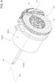
figure 3 is a perspective view of an axle of the motor vehicle offigures 1 and2 , with parts removed for greater clarity and on a much larger scale; -
figures 4 and5 show, in a perspective view and according to different view angles, a component of the axle offigure 3 ; -
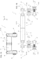
figure 6 shows an operating diagram of some components of the axle offigure 3 ; -
figure 7 shows the operating diagram offigure 6 on a larger scale and with parts removed for greater clarity; -
figure 8 is a side view of the axle offigures 2 to 7 , with parts removed for greater clarity; -
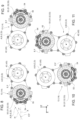
figures 9 to 14 show side views of variants of the axle offigure 8 , with parts removed for greater clarity; -
figure 15 shows an operating diagram of some components of an axle of a motor vehicle according to a second embodiment of the invention; -
figure 16 shows the operating diagram offigure 15 on a larger scale and with parts removed for greater clarity; -
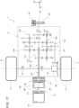
figures 17 to 19 show operating diagrams of a motor vehicle according to a third, fourth and fifth embodiment, respectively, with parts removed for greater clarity; -
figure 20 shows an operating diagram of some components of an axle of a motor vehicle according to a sixth embodiment of the invention; and -
figure 21 shows the operating diagram offigure 20 on a larger scale and with parts removed for greater clarity. - With reference to
Figures 1 and2 ,number 1 indicates a motor vehicle comprising abody 2 defining apassenger compartment 3. - The
motor vehicle 1 is a top-of-the-range motor vehicle designed both for a conventional urban/suburban use and for a racing use. - The
motor vehicle 1 is, furthermore, an electric vehicle. - Hereinafter, expressions such as "above", "under", "in front of", "behind" and others similar to them are used with reference to normal driving conditions of the
motor vehicle 1. - Furthermore, it is possible to define:
- a longitudinal axis X integral to the
body 2, which, in use, is horizontal and parallel to a normal driving direction of themotor vehicle 1 indicated in the Figure; - a transverse axis X integral to the
body 2, which, in use, is horizontal and orthogonal to the axis X; and - an axis Z integral to the
body 2, which, in use, is vertical and orthogonal to the axes X, Y. - The
body 2 defines afront 6 and a rear 7, with reference to a normal forward driving direction parallel to the axis X. - The
motor vehicle 1 is, in the specific case shown herein, has a four-wheel drive. - The
motor vehicle 1 further comprises: - a
rear axle 10; and - a
front axle 15. - The
axle 10 comprises, in turn: - a pair of
front wheels - a pair of
axle shafts front wheels - The
axle 15 comprises, in turn: - a pair of
rear wheels - a pair of
axle shafts rear wheels - Hence, the
motor vehicle 1 comprises: - an
unsprung mass 45 comprising, in turn, thefront wheels rear wheels - a sprung
mass 46 comprising, in turn, thebody 2; - a pair of
front suspensions front wheels unsprung mass 45 to thebody 2 of the sprungmass 46; - a pair of
rear suspensions rear wheels unsprung mass 45 to thebody 2 of the sprungmass 46. - Each
front suspension 24, 25 (rear suspension 26, 27) comprises, extremely in short, anelastic element 28 and a dampingelement 29 interposed between the respectivefront wheels 11, 12 (rear wheels 16, 17) and thebody 2. - Each
front suspension rear suspension front wheels 11, 12 (rear wheels 16, 17) to move, in a known manner, relative to thebody 2, following the irregularities of the ground according to an approximately vertical trajectory, hence parallel to the axis Z. - Consequently, the axes A, B (C, D) of the
front wheels 11, 12 (rear wheels 16, 17) always remain approximately parallel to the axis Y of thebody 2. - With reference to
Figures 3 to 7 , the axle 10 (15) further comprises,: - a
respective motor module 13 consisting of anelectric motor 30 with anoutput shaft 31 and atransmission assembly 40 designed to operatively connect theoutput shaft 31 to the front wheel 11 (rear wheel 16); and - a
respective motor module 14 consisting of anelectric motor 35 with anoutput shaft 36 and atransmission assembly 41 designed to operatively connect theoutput shaft 36 to the front wheel 12 (rear wheel 17). - In particular, each
electric motor relative casing respective output shaft - The
output shafts - The
transmission assemblies output shafts front wheels - Each
transmission assembly Figure 7 ): - an
intermediate shaft 44 receiving the motion from therespective output shaft gear 48 and capable of rotating at a respective rotation speed ω3; and - an
output shaft 47 receiving the motion from the respectiveintermediate shaft 44 through agear 49 and comprising a respective output power take-off respective output shaft respective axle shaft 20, 21 (22, 23) of a correspondingfront wheel 11, 12 (rear wheel 16, 17). - The
input shafts - Each
intermediate shaft 44 can rotate around an axis G of its parallel to the axes E, F and A, B (C, D). - Each
output shaft 47 can rotate around the axis A, B (C, D). - The
transmission assemblies 40 41 are interposed between thecasings electric motors - With reference to
Figures 4 to 7 , themotor vehicle 1 further comprises a plurality ofdisc brakes front wheels rear wheels - In short, each
disc brake - a
pad 54 fixed to thebody 2 in a movable manner; and - a
disc 55. - Each
pad 54 is selectively movable, due to the action of a command of a driver imparted by means of a brake pedal and/or of an automatic brake assist system, between: - a rest position, in which it is spaced apart from the
respective disc 55 and, hence, does not exert any braking torque upon therespective disc 55; and - an operating position, in which is it pressed, in a sliding manner, against the
respective disc 55 and, hence, exerts a braking torque upon therespective disc 55. - Advantageously, the
disc brakes output shafts - More in detail, each
shaft respective casing - With reference to
Figures 6 and 7 , the ends 39 of theoutput shafts ends 34 of theshafts - The
discs 55 are mounted at theends 34 of theshafts - The power take-
offs respective output shafts 47 axially arranged towards corresponding ends 34 ofrespective input shafts - As shown in
Figure 8 , the axes E, F are staggered relative to the axes A, B both along the axis X and along the axis Z. - More in detail, the axes E, F are located in front of and under the respective axes A, B (C, D).
- In particular, the axes E, F are joined by an axis H defining, with the axis X, an acute angle α smaller than 45 degrees.
- As shown in
Figures 9 to 14 , in alternative embodiments of the invention, the axes E, F are located: - behind and under the respective axes A, B (C, D) (
Figure 9 ) with an acute angle α between the axes H, X smaller than 45 degrees; - behind and under the respective axes A, B (C, D) (
Figure 10 ) with an acute angle α between the axes H, X larger than 45 degrees; - behind and above the respective axes A, B (C, D) (
Figure 11 ) and between the axes H, so that the axis H defines, with the axis X, an acute angle α larger than 45 degrees; - in front of and above the respective axes A, B (C, D) (
Figure 12 ); - in front of and under the respective axes A, B (C, D) so that the axis H defines, with the axis X, an acute angle α larger than 45 degrees (
Figure 13 ); and - behind and above the respective axes A, B (C, D) so that the axis H defines, with the axis X, an acute angle α smaller than 45 degrees (
Figure 14 ). - The
electric motors disc brakes mass 46. - In the specific case shown herein, the rotation speed ω2 is greater than the rotation speed ω3.
- The rotation speed ω3 is, in turn, greater than the rotation speed ω1.
- In use, the
electric motors axles 10; 15 cause the rotation of theoutput shafts - The
transmission assemblies output shafts axle shafts front wheels rear wheels - In case the brake pedal is operated or automatic stability control systems of the
motor vehicle 1 intervene, thepads 54 of thedisc brakes output shafts modules - Said braking torques are transmitted to the
front wheels rear wheels transmission assemblies - With reference to
Figures 15 and 16 , number 1' indicates a motor vehicle according to a different embodiment of the invention. - The motor vehicle 1' is similar to the
motor vehicle 1 and will be described below only in those aspects that distinguish the former from the latter; similar or equivalent parts of themotor vehicles 1, 1' will be indicated, when possible, with the same reference numbers. - In particular, the motor vehicle 1' differs from the
motor vehicle 1 in that thecasings electric motors respective transmission assemblies - Furthermore, the motor vehicle 1' differs from the
motor vehicle 1 in that thediscs 55 of thebrakes intermediate shafts 44 of therespective transmission assemblies - The operation of the motor vehicle 1' differs from the operation of the
motor vehicle 1 in that thediscs 55 exert the respective braking torques upon theintermediate shafts 44 capable of rotating at respective rotation speeds ω3. - With reference to
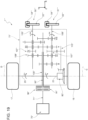
Figure 17 ,number 1" indicates a motor vehicle according to a different embodiment of the invention. - The
motor vehicle 1" is similar to themotor vehicle 1 and will be described below only in those aspects that distinguish the former from the latter; similar or equivalent parts of themotor vehicles - More in detail, the
motor vehicle 1" differs from themotor vehicle 1 in that it is a rear-wheel drive hybrid vehicle. - Furthermore, the
motor vehicle 1" differs from themotor vehicle 1 in that it comprises: - an
internal combustion engine 70" configured to cause the rotation of anoutput shaft 71" of its; - an
electric machine 85" comprising an input shaft 86'' and anoutput shaft 87"; - a clutch 72", which can selectively be operated to couple or uncouple the
output shaft 71" of the engine 70'' and the input shaft 86'' of theelectric machine 85"; - a dual-
clutch gearbox 75" provided with anoutput shaft 115"; and - a differential 80", which receives the motion from the
output shaft 115" and transfers it to theaxle shafts rear wheels - In particular, the
gearbox 75" comprises: - two
primary shafts 95" and 100'' coaxial to one another and with axis Z, independent and inserted inside one another; - two
coaxial clutches 90" and 91" arranged in series, each designed to connect a respectiveprimary shaft 95" or 100" to theoutput shaft 87" of theelectric machine 85"; and - two
secondary shafts 105" and 106'', which are both angularly integral to the input of the differential 80" through theoutput shaft 115". - The
primary shafts 95" and 100'' are mechanically coupled to thesecondary shafts 105" and 106'' by means of a plurality of gear pairs 107'', each defining a respective gear and comprising a primary gear wheel mounted on ashaft 95" or 100'' and a secondary gear wheel, which is mounted on asecondary shaft 105" or 106'' and permanently meshes with the primary gear wheel. In order to allow for a correct operation of the dual-clutch gearbox 75'', all odd gears (first gear I, third gear III, fifth gear V, seventh gear VII) are coupled to the sameprimary shaft 95", whereas all even gears (second gear II, fourth gear IV and sixth gear VI) are coupled to the otherprimary shaft 100". - Each primary gear wheel is splined to a respective
primary shaft 95", 100", so as to always rotate with theprimary shaft 95", 100" in an integral manner, and permanently meshes with the respective secondary gear wheel; on the other hand, each secondary gear wheel is mounted idle on its own secondary shaft 105'', 106''. - The dual-
clutch gearbox 75" further comprises, for eachgear pair 107", a correspondingsynchronizer 108", which is coaxial to the relativesecondary shaft 105", 106" and is designed to be actuated so as to engage the respective secondary gear wheel on thesecondary shaft 105" or 106" (i.e. so as to cause the secondary gear wheel to become angularly integral to thesecondary shaft 105" or 106"). - In particular, the
shafts 105", 106" rotate at respective rotation speeds ω5, ω6, which are different from and greater than the rotation speed ω1. - In a known manner, the differential 80" is configured to cause the rotation of the
axle shafts rear wheels motor vehicle 1" travels along a straight trajectory, and at corresponding rotations speeds ω1, which are different from one another when themotor vehicle 1" travels along a curved trajectory. - Furthermore, the
motor vehicle 1" differs from themotor vehicle 1 in that it comprises onesingle disc brake 50" with one single disc 55'' splined on theprimary shaft 95" capable of rotating at a rotation speed ω2, which is different from and, in particular, greater than the rotation speed ω1. - The
disc brake 50" can selectively be operated so as to directly exert a braking torque upon theprimary shaft 95" capable of rotating, in use, at the rotation speed ω2, which is different from and, in particular, greater than the rotation speed ω1. - The operation of the
motor vehicle 1" differs from the operation of themotor vehicle 1 in that it can offer: - a heat operating mode, in which the clutch 72" couples the
shafts 71" and 86'', the drive torque is generated by the sole engine 70'' and theelectric machine 85" is deactivated; - an electric operating mode, in which the engine 70'' is deactivated and/or the clutch 72" uncouples the
shafts 71" and 86" and the drive torque is generated by the soleelectric machine 85" operated as electric motor; or - a combined operating mode, in which the clutch 72" couples the
shafts 71" and 86'' , the drive torque is generated both by theengine 70" and by theelectric machine 85" operated as electric motor. - Regardless of the selected operating mode, the
output shaft 87" is subjected to a drive torque and is connected by the clutch 90" to theprimary shaft 95" or by the clutch 91" to theprimary shaft 100". - In particular, the
primary shaft 95" rotates around an axis Z of its at a rotation speed ω2, which is different from and, in particular, greater than the rotation speed ω1. - The
gearbox 75" transmits the motion, with the requested gear, from theprimary shaft 95" or from theprimary shaft 100" to theoutput shaft 115" connected to the differential 80". The differential 80" causes the rotation of theaxle shafts rear wheels motor vehicle 1" travels along a straight trajectory, and at corresponding rotations speeds ω1, which are different from one another when themotor vehicle 1" travels along a curved trajectory. - In case the brake pedal is activated, the
pad 54" moves from the rest position to the operating position, thus exerting a braking torque upon the disc 55'' integral to theprimary shaft 95" capable of rotating at respective rotation speeds ω2. - Said braking torque is transmitted to the
rear wheels secondary shaft 105", by the output shaft 110" and by the differential 80". - In case the brake pedal is activated, the clutch 72'' uncouples the
shafts 71" and 86'' and theelectric machine 85" is operated as electric generator. In this way, part of the kinetic energy of thesecondary shaft 105" and, hence, of therear wheels - With reference to
Figure 18 ,number 1‴ indicates a motor vehicle according to a different embodiment of the invention. - The
motor vehicle 1‴ is similar to themotor vehicle 1" and will be described below only in those aspects that distinguish the former from the latter; similar or equivalent parts of themotor vehicles 1", 1‴ will be indicated, when possible, with the same reference numbers. - The motor vehicle 1''' differs from the
motor vehicle 1" in that it does not comprise the clutch 72‴ and in that theoutput shaft 87" of theelectric machine 85" coincides with or is angularly integral to theprimary shaft 95" of thegearbox 75". In this way, theinternal combustion engine 70‴ and theelectric machine 85" operated as motor are in parallel to one another. - The operation of the
motor vehicle 1‴ differs from the operation of themotor vehicle 1" in that the activation of theelectric machine 85" as electric motor determines a further drive torque exerted upon theprimary shaft 95" of thegearbox 75" and in that the activation of thedisc brake 50‴ allows the kinetic energy of theprimary shaft 95‴ to be converted into electrical energy through the use of theelectric machine 85‴ as electric generator. - With reference to
Figure 19 , number 1ʺʺ indicates a motor vehicle according to a different embodiment of the invention. - The motor vehicle 1ʺʺ is similar to the
motor vehicle 1" and will be described below only in those aspects that distinguish the former from the latter; similar or equivalent parts of themotor vehicles 1", 1ʺʺ will be indicated, when possible, with the same reference numbers. - More in detail, the motor vehicle 1ʺʺ differs from the
motor vehicle 1" in that it is heat-operated vehicle. - More in particular, the motor vehicle 1ʺʺ differs from the
motor vehicle 1" in that it does not comprise theelectric machine 85" and the clutch 95‴. - Furthermore, the motor vehicle 1ʺʺ differs from the
motor vehicle 1" in that it comprises: - a disc brake 50ʺʺ comprising a
disc 54"" splined to thesecondary shaft 105" capable of rotating at a rotation speed ω5, which is different from and, in the specific case shown herein, greater than the rotation speed ω1 of therear wheels - a disc brake 51ʺʺ comprising a
disc 54"" splined to thesecondary shaft 106" capable of rotating at a rotation speed ω6, which is different from and, in the specific case shown herein, greater than the rotation speed ω1 of therear wheels - The operation of the motor vehicle 1ʺʺ differs from the operation of the
motor vehicle 1" in that it can offer the sole heat operating mode. - Furthermore, the operation of the motor vehicle 1ʺʺ differs from the operation of the
motor vehicle 1" in that, in case the brake pedal is activated, the disc brake 50ʺʺ exerts a first braking torque upon thesecondary shaft 105" capable of rotating at a rotation speed ω5, which is different from and greater than the rotation speed ω1, and the disc brake 51ʺʺ exerts a second braking torque upon thesecondary shaft 106" capable of rotating at a rotation speed ω6, which is different from and greater than the rotation speed ω1. - Said first and second braking torques are transmitted to the
rear wheels output shaft 115" and by the differential 80". - With reference to
Figure 20 ,number 1‴ʺ indicates a motor vehicle according to a different embodiment of the invention. - The
motor vehicle 1‴ʺ is similar to themotor vehicle 1" and will be described below only in those aspects that distinguish the former from the latter; similar or equivalent parts of themotor vehicles - In particular, the
motor vehicle 1‴ʺ differs from themotor vehicle 1 in that the power take-off 42‴ʺ (43‴ʺ) of themodule 13‴ʺ (14‴ʺ) of therespective output shaft 47 is axially located on the side of theend 39 of theoutput shaft 31. - The operation of the
motor vehicle 1‴ʺ is similar to the one of themotor vehicle 1 and, therefore, it will not be described in detail. - The disclosure above reveals evident advantages that can be reached with the invention.
- In particular, the
disc brakes output shaft intermediate shaft 44, the primary shaft 95''; the secondary shafts 105'', 106" - which rotates at a rotation speed ω2; ω3; ω2; ω5, ω6 that is different from and, in particular, greater than the rotation speed ω1 of thefront wheels - Therefore, the braking torque requested to the
disc brake output shaft intermediate shaft 44, the primary shaft 95''; thesecondary shafts 105", 106'' have rotation speeds ω2; ω3; ω2; ω5, ω6 that are greater than the rotation speed ω1 of thefront wheels rear wheels disc brakes - This dimension and weight reduction is particularly relevant for the
motor vehicles output shafts electric motors - This dimension and weight reduction is particularly advantageous in the
motor vehicles electric machines disc brakes aforesaid motor vehicles electric machines disc brakes - Thanks to the fact that the
disc brakes front wheels 11, 12 (andrear wheels 16, 17), designers have utmost manufacturing flexibility when dealing with the layout of thefront wheels 11, 12 (andrear wheels 16, 17). - Finally, thanks to the fact that the
disc brakes mass 46, the dynamics of themotor vehicle 1, 1', 1'', 1‴, 1ʺʺ, 1‴ʺ can significantly be improved. - Finally, the
motor vehicle - In particular, the
motor vehicle 1, 1' could be a front-wheel drive vehicle and comprise thesole modules axle 10. Alternatively, themotor vehicle 1, 1' could be a rear-wheel drive vehicle and comprise thesole modules axle 15. - Similarly, the
motor vehicle 1", 1‴, 1ʺʺ could be a front-wheel drive vehicle. In this case, the differential 80" would be connected to theaxle shafts front wheels motor vehicle 1", 1‴, 1ʺʺ could be an all-wheel drive vehicle. In this case, theoutput shaft 115" of thegearbox 75" would also be connected to theaxle shafts front wheels - The
motor vehicle 1""' could comprisefurther modules 13‴ʺ, 14‴ʺ connected to the remainingfront wheels 12 and/or to therear wheels - Finally, the
motor vehicle disc brakes
Claims (11)
- A motor vehicle (1, 1', 1", 1‴, 1ʺʺ, 1‴ʺ) comprising:- at least one first driving member (30, 35; 70"; 85");- at least one wheel (11, 12; 16, 17), which is angularly integral to a first shaft (20, 21; 22, 23), is operatively connected to said first driving member (30, 35; 70"; 85") and can rotate, in use, with a first rotation speed (ω1); and- at least one brake (50, 51, 52, 53; 50"; 50‴; 50ʺʺ, 51ʺʺ);said brake (50, 51, 52, 53; 50", 51"; 50ʺʺ, 51ʺʺ) can selectively be operated so as to directly exert a braking torque upon a second shaft (31, 36; 44; 95", 105", 106") of said motor vehicle (1, 1', 1", 1‴, 1ʺʺ, 1‴ʺ) other than said first shaft (20, 21; 22, 23) and capable of rotating, in use, with a second rotation speed (ω2; ω3; ω2; ω5, ω6), which is different from said first rotation speed (ω1);said second shaft (31, 36; 44; 95", 105", 106") being operatively connected to said first shaft (20, 21; 22, 23);said first driving member (30, 35) being an electric driving member;said motor vehicle (1, 1', 1", 1‴, 1ʺʺ, 1‴ʺ) further comprising:- a second heat driving member (70") provided with a second output member (71"); and- a gearbox (75'') interposed between said driving member (70") and at least two wheels (11, 12; 16, 17);said gearbox (75") comprising said second shaft (95", 105", 106") and being capable of being selectively operated so as to change, in a discrete manner and according to a plurality of gears (I, II, III, IV, V, VI, VII), the ratio between said first rotation speed (ω1) and a third rotation speed (ω2), with which, in use, said second output member (71") of said driving member (70") rotates;characterized in that it further comprises:- a first clutch (72") configured to connect, in a selectively releasable manner, said second output member (71") and a third input shaft (86'') of said first driving member (85"); and- a second clutch (90", 91") configured to connect, in a selectively releasable manner, said third input shaft (86") to said gearbox (75").
- The motor vehicle according to claim 1, characterized in that said second shaft (31, 36) is a first output member of said first driving member (30, 35).
- The motor vehicle according to claim 2, characterized in that said first driving member (30, 35) comprises a casing (33, 38) supporting said second shaft (31, 36) in a rotary manner;said second shaft (31, 36) comprising, in turn:- a first segment (39) operatively connected to said first shaft (20, 21; 22, 23); and- a second segment (34), upon which said brake (50, 51) exerts, in use, said braking torque;said first and second segment (39, 34) axially projecting from respective sides of said casing (33, 38), which are axially opposite one another.
- The motor vehicle according to claim 1, characterized in that it comprises a transmission assembly (40, 41), which is configured to transmit the motion from said first driving member (30, 35) to said wheel (11, 12; 16, 17) and comprises said second shaft (44);
said transmission assembly (40, 41) being configured to provide at least a gear ratio that is different from one of said first rotation speed (ω1) and said second rotation speed (ω2, ω3). - The motor vehicle according to any one of the preceding claims, characterized in that it comprises:- a pair of said first driving members (30, 35) operatively connected to respective wheels (11, 12; 16, 17) capable of rotating around respective first shafts (20, 21; 22, 23); and- a pair of said second shafts (31, 36; 44), each associated with a respective driving member (30, 35) and with a respective wheel (11, 12; 16, 17).
- The motor vehicle according to any one of the preceding claims, characterized in that said first shaft (20, 21; 22, 23) and said second shaft (31, 36; 44) can rotate around a first axis (A, B, C, D) and a second axis (E, F; G), respectively, which are staggered relative to one another.
- The motor vehicle according to claim 6, characterized in that it comprises:- a third axis (X), which is longitudinal and parallel, in use, to a normal forward driving direction of the motor vehicle (1);- a fourth axis (Z), which is orthogonal to said third axis (X) and is arranged, in use, in a vertical manner;said first axis (A, B, C, D) and said second axis (E, F; G) being spaced apart from one another both parallel to said third axis (X) and parallel to said fourth axis (Z).
- The motor vehicle according to any one of the preceding claims, characterized in that said second shaft (95") is an output member of said electric motor (85").
- The motor vehicle according to claim 1, characterized in that said first driving member (70") is an internal combustion engine;said motor vehicle (1ʺʺ) further comprising:- a gearbox (75") interposed between said an output member (71") of said first driving member (70") and at least two wheels (11, 12; 16, 17);said gearbox (75") being capable of being selectively operated so as to change, in a discrete manner and according to a plurality of gears (I, II, III, IV, V, VI, VII), the ratio between said first rotation speed (ω1) and a third rotation speed (ω2), with which, in use, said output member (71") of said first driving member (70") rotates;said gearbox (75") defining said second shaft (105").
- The motor vehicle according to any one of the preceding claims, characterized in that said second rotation speed (ω2; ω3; ω2; ω5, ω6) is greater than said first rotation speed (ω1).
- The motor vehicle according to any one of the preceding claims, characterized in that it comprises:- a body (2);- an unsprung mass (45) comprising said wheel (11, 12; 16, 17);- a sprung mass (46) comprising said body (2), said first driving member (30, 35; 70"; 85") and said brake (50, 51, 52, 53; 50", 51"; 50ʺʺ, 51""); andat least one suspension (24, 25) designed to connect said unsprung mass (45) and said sprung mass (46) to one another in an elastic manner.
Applications Claiming Priority (1)
| Application Number | Priority Date | Filing Date | Title |
|---|---|---|---|
| IT102023000007065A IT202300007065A1 (en) | 2023-04-13 | 2023-04-13 | MOTOR VEHICLE |
Publications (1)
| Publication Number | Publication Date |
|---|---|
| EP4446179A1 true EP4446179A1 (en) | 2024-10-16 |
Family
ID=86942843
Family Applications (1)
| Application Number | Title | Priority Date | Filing Date |
|---|---|---|---|
| EP24169156.7A Pending EP4446179A1 (en) | 2023-04-13 | 2024-04-09 | Motor vehicle |
Country Status (3)
| Country | Link |
|---|---|
| US (1) | US20240343230A1 (en) |
| EP (1) | EP4446179A1 (en) |
| IT (1) | IT202300007065A1 (en) |
Citations (8)
| Publication number | Priority date | Publication date | Assignee | Title |
|---|---|---|---|---|
| US20030064854A1 (en) * | 2001-09-28 | 2003-04-03 | Toyota Jidosha Kabushiki Kaisha | Power output apparatus and automobile with power output apparatus mounted thereon |
| US20150375734A1 (en) * | 2012-06-27 | 2015-12-31 | Scania Cv Ab | Method for controlling a drive system of a vehicle, a drive system, a computer program, a computer program product and a vehicle |
| US20170087975A1 (en) | 2015-09-24 | 2017-03-30 | Ferrari S.p.A, | Road vehicle with an electric drive |
| EP3597464A1 (en) | 2018-07-17 | 2020-01-22 | FERRARI S.p.A. | Motor vehicle comprising an electric axle |
| US20210010567A1 (en) * | 2019-07-08 | 2021-01-14 | Daimler Ag | Hybrid dual-clutch transmission |
| US20220034789A1 (en) | 2018-10-30 | 2022-02-03 | Specshell Aps | Non-invasive continuous in line antifouling of atr-mir spectroscopic sensors |
| US20220314789A1 (en) * | 2020-04-01 | 2022-10-06 | Kessler & Co. Gmbh & Co. Kg | Axle drive |
| US11498561B1 (en) | 2018-04-09 | 2022-11-15 | Apple Inc. | Vehicle deceleration system |
Family Cites Families (3)
| Publication number | Priority date | Publication date | Assignee | Title |
|---|---|---|---|---|
| US6698313B2 (en) * | 2002-01-15 | 2004-03-02 | Fairway Golf Cars, Llc | Dual motor gear drive unit |
| DE102012205823A1 (en) * | 2012-04-11 | 2013-10-17 | Zf Friedrichshafen Ag | Drive device of a vehicle and method for its operation |
| DE102017124592A1 (en) * | 2017-10-20 | 2019-05-09 | Thyssenkrupp Ag | Electric drive unit and motor vehicle |
-
2023
- 2023-04-13 IT IT102023000007065A patent/IT202300007065A1/en unknown
-
2024
- 2024-04-08 US US18/629,370 patent/US20240343230A1/en active Pending
- 2024-04-09 EP EP24169156.7A patent/EP4446179A1/en active Pending
Patent Citations (8)
| Publication number | Priority date | Publication date | Assignee | Title |
|---|---|---|---|---|
| US20030064854A1 (en) * | 2001-09-28 | 2003-04-03 | Toyota Jidosha Kabushiki Kaisha | Power output apparatus and automobile with power output apparatus mounted thereon |
| US20150375734A1 (en) * | 2012-06-27 | 2015-12-31 | Scania Cv Ab | Method for controlling a drive system of a vehicle, a drive system, a computer program, a computer program product and a vehicle |
| US20170087975A1 (en) | 2015-09-24 | 2017-03-30 | Ferrari S.p.A, | Road vehicle with an electric drive |
| US11498561B1 (en) | 2018-04-09 | 2022-11-15 | Apple Inc. | Vehicle deceleration system |
| EP3597464A1 (en) | 2018-07-17 | 2020-01-22 | FERRARI S.p.A. | Motor vehicle comprising an electric axle |
| US20220034789A1 (en) | 2018-10-30 | 2022-02-03 | Specshell Aps | Non-invasive continuous in line antifouling of atr-mir spectroscopic sensors |
| US20210010567A1 (en) * | 2019-07-08 | 2021-01-14 | Daimler Ag | Hybrid dual-clutch transmission |
| US20220314789A1 (en) * | 2020-04-01 | 2022-10-06 | Kessler & Co. Gmbh & Co. Kg | Axle drive |
Also Published As
| Publication number | Publication date |
|---|---|
| US20240343230A1 (en) | 2024-10-17 |
| IT202300007065A1 (en) | 2024-10-13 |
Similar Documents
| Publication | Publication Date | Title |
|---|---|---|
| US20230415569A1 (en) | Driving apparatus for vehicle | |
| JP5318387B2 (en) | Axle drive unit for drivetrain | |
| EP1950072B1 (en) | Arrangement of in-wheel motor and suspension links for vehicle | |
| US7467678B2 (en) | Hybrid four-wheel-drive | |
| US7455612B2 (en) | Rotatively driving apparatus | |
| US20080176707A1 (en) | Vehicle Drive Device | |
| US20050107198A1 (en) | Hybrid powertrain | |
| US7780563B2 (en) | Drive force distribution apparatus | |
| US20060225930A1 (en) | Dual axle electric motor drive and method of use | |
| GB2305643A (en) | Vehicle with hybrid internal combustion engine and electric motor drive | |
| JP5375378B2 (en) | Hybrid vehicle drive device | |
| US20120142474A1 (en) | Drive unit, particularly rear drive unit, for an all-wheel drive of a motor vehicle | |
| US20140011620A1 (en) | Drive device for driving a wheel of a spring strut-type axle for an electrically drivable vehicle | |
| CA2572847A1 (en) | Independent axle motors for a road coupled hybrid vehicle | |
| CN101557959A (en) | Differential gearing | |
| JP6997584B2 (en) | Hybrid vehicle power unit | |
| CN115195431A (en) | Power transmission for a utility vehicle having an electric axle | |
| US20130324359A1 (en) | Power transmission apparatus for four-wheel-drive hybrid vehicle | |
| CN117203074A (en) | Hybrid systems and vehicles | |
| JP2023102684A (en) | front and rear wheel independent drive vehicle | |
| EP4446179A1 (en) | Motor vehicle | |
| JP3618901B2 (en) | Vehicle propulsion device | |
| KR102715815B1 (en) | Device for torque vectoring | |
| WO2007039730A1 (en) | Hubs for electric hybrid vehicles | |
| CN105313594B (en) | Transmission shaft component |
Legal Events
| Date | Code | Title | Description |
|---|---|---|---|
| PUAI | Public reference made under article 153(3) epc to a published international application that has entered the european phase |
Free format text: ORIGINAL CODE: 0009012 |
|
| STAA | Information on the status of an ep patent application or granted ep patent |
Free format text: STATUS: THE APPLICATION HAS BEEN PUBLISHED |
|
| AK | Designated contracting states |
Kind code of ref document: A1 Designated state(s): AL AT BE BG CH CY CZ DE DK EE ES FI FR GB GR HR HU IE IS IT LI LT LU LV MC ME MK MT NL NO PL PT RO RS SE SI SK SM TR |
|
| STAA | Information on the status of an ep patent application or granted ep patent |
Free format text: STATUS: REQUEST FOR EXAMINATION WAS MADE |
|
| 17P | Request for examination filed |
Effective date: 20250131 |