EP4446174A1 - Impact absorption device - Google Patents
Impact absorption device Download PDFInfo
- Publication number
- EP4446174A1 EP4446174A1 EP22903801.3A EP22903801A EP4446174A1 EP 4446174 A1 EP4446174 A1 EP 4446174A1 EP 22903801 A EP22903801 A EP 22903801A EP 4446174 A1 EP4446174 A1 EP 4446174A1
- Authority
- EP
- European Patent Office
- Prior art keywords
- impact absorbing
- absorbing member
- impact
- absorption device
- state
- Prior art date
- Legal status (The legal status is an assumption and is not a legal conclusion. Google has not performed a legal analysis and makes no representation as to the accuracy of the status listed.)
- Pending
Links
Images






Classifications
-
- B—PERFORMING OPERATIONS; TRANSPORTING
- B60—VEHICLES IN GENERAL
- B60R—VEHICLES, VEHICLE FITTINGS, OR VEHICLE PARTS, NOT OTHERWISE PROVIDED FOR
- B60R21/00—Arrangements or fittings on vehicles for protecting or preventing injuries to occupants or pedestrians in case of accidents or other traffic risks
- B60R21/02—Occupant safety arrangements or fittings, e.g. crash pads
-
- B—PERFORMING OPERATIONS; TRANSPORTING
- B60—VEHICLES IN GENERAL
- B60R—VEHICLES, VEHICLE FITTINGS, OR VEHICLE PARTS, NOT OTHERWISE PROVIDED FOR
- B60R21/00—Arrangements or fittings on vehicles for protecting or preventing injuries to occupants or pedestrians in case of accidents or other traffic risks
- B60R21/02—Occupant safety arrangements or fittings, e.g. crash pads
- B60R21/04—Padded linings for the vehicle interior ; Energy absorbing structures associated with padded or non-padded linings
-
- B—PERFORMING OPERATIONS; TRANSPORTING
- B60—VEHICLES IN GENERAL
- B60R—VEHICLES, VEHICLE FITTINGS, OR VEHICLE PARTS, NOT OTHERWISE PROVIDED FOR
- B60R19/00—Wheel guards; Radiator guards, e.g. grilles; Obstruction removers; Fittings damping bouncing force in collisions
- B60R19/02—Bumpers, i.e. impact receiving or absorbing members for protecting vehicles or fending off blows from other vehicles or objects
- B60R19/24—Arrangements for mounting bumpers on vehicles
- B60R19/38—Arrangements for mounting bumpers on vehicles adjustably or movably mounted, e.g. horizontally displaceable for securing a space between parked vehicles
- B60R19/40—Arrangements for mounting bumpers on vehicles adjustably or movably mounted, e.g. horizontally displaceable for securing a space between parked vehicles in the direction of an obstacle before a collision, or extending during driving of the vehicle, i.e. to increase the energy absorption capacity of the bumper
-
- F—MECHANICAL ENGINEERING; LIGHTING; HEATING; WEAPONS; BLASTING
- F16—ENGINEERING ELEMENTS AND UNITS; GENERAL MEASURES FOR PRODUCING AND MAINTAINING EFFECTIVE FUNCTIONING OF MACHINES OR INSTALLATIONS; THERMAL INSULATION IN GENERAL
- F16F—SPRINGS; SHOCK-ABSORBERS; MEANS FOR DAMPING VIBRATION
- F16F7/00—Vibration-dampers; Shock-absorbers
-
- B—PERFORMING OPERATIONS; TRANSPORTING
- B60—VEHICLES IN GENERAL
- B60R—VEHICLES, VEHICLE FITTINGS, OR VEHICLE PARTS, NOT OTHERWISE PROVIDED FOR
- B60R21/00—Arrangements or fittings on vehicles for protecting or preventing injuries to occupants or pedestrians in case of accidents or other traffic risks
- B60R21/02—Occupant safety arrangements or fittings, e.g. crash pads
- B60R2021/0273—Occupant safety arrangements or fittings, e.g. crash pads automatically movable to an operative position, e.g. in case of collision or impending collision
-
- F—MECHANICAL ENGINEERING; LIGHTING; HEATING; WEAPONS; BLASTING
- F16—ENGINEERING ELEMENTS AND UNITS; GENERAL MEASURES FOR PRODUCING AND MAINTAINING EFFECTIVE FUNCTIONING OF MACHINES OR INSTALLATIONS; THERMAL INSULATION IN GENERAL
- F16F—SPRINGS; SHOCK-ABSORBERS; MEANS FOR DAMPING VIBRATION
- F16F2234/00—Shape
- F16F2234/06—Shape plane or flat
Definitions
- the present disclosure relates to an impact absorption device that relieves an impact when activated.
- Patent Document 1 describes an energy absorber for protecting a pedestrian or the like colliding with a bumper of a vehicle by relieving an impact generated on the bumper of the vehicle.
- this energy absorber respective gaps between a plurality of fins connected to a base and absorbing an impact are formed.
- Patent Document 1 US 10,046,723
- an impact absorption device a region where an impact absorbing member can flex needs to be formed.
- the respective gaps between the plurality of fins correspond to such a region.
- the impact absorption device has a bulky structure as a whole when this region is formed, and thus the position of the impact absorption device to be mounted on the vehicle is limited, and a degree of freedom of an arrangement position thereof is reduced.
- an object of the present disclosure is to provide an impact absorption device capable of improving a degree of freedom of an arrangement position thereof.
- the present disclosure adopts the following configuration.
- An impact absorption device configured to relieve an impact when activated includes an impact absorbing member, an auxiliary member, and a drive unit.
- the impact absorbing member has flexibility and is attached to a base portion in a manner reversibly switchable between a retracted state in which the impact absorbing member is retracted toward an installation surface of the base portion and a protruding state in which the impact absorbing member protrudes from the installation surface.
- the auxiliary member has flexibility and is attached to the base portion in a manner reversibly switchable between a retracted state in which the auxiliary member is retracted toward the installation surface and a protruding state in which the auxiliary member protrudes from the installation surface in synchronization with the retracted state and the protruding state of the impact absorbing member.
- the drive unit is configured to directly or indirectly drive the impact absorbing member when the impact absorbing member and the auxiliary member are activated, thereby switching the impact absorbing member at least from the retracted state to the protruding state.
- the impact absorbing member is attached to the installation surface of the base portion rotatably about a first pivoting axis extending in a first direction, and is reversibly switched between the retracted state and the protruding state by being rotationally driven about the first pivoting axis.
- the auxiliary member is attached to the installation surface rotatably about a second pivoting axis extending in a second direction intersecting the first direction, and is reversibly switched between the retracted state and the protruding state by being rotationally driven about the second pivoting axis.
- a height of the impact absorbing member from the base portion in the protruding state is higher than that of the auxiliary member.
- At least a portion of the impact absorbing member and at least a portion of the auxiliary member face each other, and the impact absorbing member deforms when receiving a load including a component in a direction opposite to the installation surface side of the base portion, thereby engaging with the auxiliary member.
- the auxiliary member may restrict the impact absorbing member from rotating about the first pivoting axis and switching to the retracted state when the impact absorbing member receives the load in the protruding state.
- the impact absorbing member may include a first groove formed at a position facing the auxiliary member in the protruding state and engageable with a portion of the auxiliary member, and at least a portion of the impact absorbing member may deform toward the auxiliary member when the impact absorbing member receives the load, thereby causing the first groove to engage with a portion of the auxiliary member.
- the auxiliary member may include a protruding portion formed at a position facing the first groove in the protruding state and protruding in the second direction, and the auxiliary member may deform in the first direction when the auxiliary member receives the load, thereby causing the protruding portion to engage with the first groove.
- a portion of the impact absorbing member may deform into a protruding shape in the second direction when the impact absorbing member receives the load, the second direction being predetermined, and the auxiliary member may include a second groove engageable with the impact absorbing member by being deformed and sandwiching the portion of the impact absorbing member deformed into the protruding shape when receiving the load.
- the impact absorbing member may include a deformation support portion formed in the first direction, causing deformation to preferentially occur in the second direction when the impact absorbing member receives the load.
- the impact absorbing member may have greater flexibility than that of the auxiliary member.
- the impact absorbing member may include a plurality of impact absorbing members disposed in a plurality of columns, the plurality of impact absorbing members being spaced apart in a direction orthogonal to the first direction, and each of the plurality of impact absorbing members provided in the plurality of columns may be maintained in a lying posture along the installation surface in the retracted state, rotationally driven in a predetermined activating direction about the first pivoting axis and switched from the lying posture to a standing posture in which the impact absorbing member is erected from the installation surface, when being switched from the retracted state to the protruding state, and rotationally driven in a standing-to-lying direction opposite to the activating direction about the first pivoting axis and switched from the standing posture to the lying posture, when being switched from the protruding state to the retracted state.
- the auxiliary member may be disposed between each column of the plurality of impact absorbing members of the plurality of columns, maintained in a lying posture along the installation surface in the retracted state, with a portion of an impact absorbing member of the plurality of impact absorbing members in an adjacent column covering, from above, at least a portion of the auxiliary member, rotationally driven in a predetermined activating direction about the second pivoting axis and switched from the lying posture to a standing posture, when being switched from the retracted state to the protruding state, and rotationally driven in the standing-to-lying direction opposite to the activating direction about the second pivoting axis and switched from the standing posture to the lying posture, when being switched from the protruding state to the retracted state.
- the auxiliary member may face, of the plurality of impact absorbing members, impact absorbing members in adjacent columns on both sides, in the protruding state.
- the impact absorption device described above may further include one or more driving force transmitting members coupled to the auxiliary member, at least partially having flexibility, and driven by the drive unit, and the one or more driving force transmitting members may be driven when the drive unit activates the impact absorbing member, thereby causing the auxiliary member to switch from the lying posture to the standing posture, and the impact absorbing member to switch from the lying posture to the standing posture, accompanying the auxiliary member.
- the impact absorption device described above may include a plurality of the auxiliary members and one of the driving force transmitting members, and the plurality of auxiliary members may be coupled to the driving force transmitting member.
- the one or more driving force transmitting members may each include a plate-shaped portion and may be driven by the drive unit while maintaining a state in which the plate-shaped portion is parallel to the installation surface.
- the first direction and the second direction may be orthogonal to each other.
- a degree of freedom of an arrangement position of the impact absorption device can be improved.
- the impact absorption device is mounted on a vehicle such as an automobile, and is exemplified as a device for protecting an occupant in the vehicle.
- the impact absorption device is attached to an attachment target which constitutes the vehicle and protects the occupant when activated.
- the attachment target which constitutes the vehicle include a structure which constitutes the vehicle body such as a pillar or a ceiling, and a structure which constitutes the vehicle body such as a dashboard or a steering wheel.
- the impact absorption device is fixed to the vehicle by being attached to such an attachment target.
- a base portion itself may be the attachment target itself, or an impact absorbing portion 12 or the like described below may be directly provided to the attachment target.
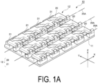
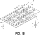
- FIGS. 1A and 1B are perspective views schematically illustrating an appearance of the impact absorption device 10 according to the present embodiment.
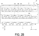
- FIGS. 2A and 2B are plan views schematically illustrating the appearance of the impact absorption device 10 according to the present embodiment.
- the impact absorption device 10 includes a base portion 11 attached to an attachment target of a vehicle, and the impact absorbing portion 12 attached to a front surface (an example of an "installation surface") side of the base portion 11.
- the base portion 11 has a rectangular plate-like shape, and the impact absorbing portion 12 is arranged on the front surface side of the base portion 11, and a back surface side thereof is attached to an attachment target.
- a direction along a long side of the base portion 11 is defined as an X-axis
- a direction along a short side of the base portion 11 is defined as a Y-axis
- a direction orthogonal to both the X-axis and the Y-axis is defined as a Z-axis.
- the impact absorption device 10 is a device for protecting an occupant to be protected and positioned in the Z-axis direction. Note that the direction along the X-axis is defined as a "row" of the matrix, and the direction along the Y-axis is defined as a "column" of the matrix.
- the impact absorbing portion 12 has flexibility as a whole, and absorbs a force (load) applied to an occupant by deforming when an accident or the like occurs in a vehicle and an inertial force is generated on the occupant, causing the occupant to collide with the impact absorbing portion 12.
- the impact absorbing portion 12 relieves the impact on the occupant and protects the occupant.
- the impact absorbing portion 12 is configured to protrude toward a cabin occupied by the occupant. More specifically, the impact absorbing portion 12 is configured to be reversibly switchable between a retracted state in which the impact absorbing portion 12 is retracted from the cabin toward the base portion 11 and a protruding state in which the impact absorbing portion 12 protrudes from the base portion 11 toward the cabin. In the state illustrated in FIGS. 1A to 2B , the impact absorbing portion 12 is in the retracted state.
- the impact absorbing portion 12 includes an impact absorbing member 20, a fin 21 (an example of an "auxiliary member"), and a top plate portion 22 (an example of a “driving force transmitting member"). Note that, in FIGS. 1A and 2A , the top plate portion 22 is not illustrated for description.
- the impact absorbing member 20 is formed of rubber or the like and has deformable flexibility such as elasticity.
- the impact absorbing member 20 has a shape in which the direction in the X-axis direction is a longitudinal direction (shape extending integrally in the X-axis direction), and three impact absorbing members 20 are arranged in three columns in the Y-axis direction.
- the impact absorbing member 20 is attached to the front surface side of the base portion 11 rotatably about a pivoting axis 20A (an example of a "first pivoting axis”) extending in a direction (an example of a "first direction”) along the X-axis with respect to the front surface of the base portion 11.
- a pivoting axis 20A an example of a "first pivoting axis"
- the pivoting axis 20A is represented by a dashed line.
- Respective pivoting axes 20A of the three impact absorbing members 20 are spaced apart from each other in a direction along the Y-axis (an example of a "second direction"), making it possible for each impact absorbing member 20 to operate without interfering with each other.
- three impact absorbing members provided in three columns may be referred to as a plurality of columns of impact absorbing members 20.
- the impact absorbing portion 12 includes the plurality of columns of impact absorbing members 20.
- Each of the plurality of columns of impact absorbing members 20 is maintained in a lying posture along the front surface of the base portion 11 in the retracted state, as illustrated in FIG. 1A .
- Each of the plurality of columns of impact absorbing members 20 is rotationally driven in an activating direction about the pivoting axis 20A when being switched from the retracted state to the protruding state, and thus switches from the lying posture to a standing posture in which the impact absorbing member 20 is erected from the front surface of the base portion 11.
- the activating direction of the impact absorbing member 20 is clockwise when viewed toward the positive direction of the X-axis.
- each of the plurality of columns of impact absorbing members 20 When being switched from the protruding state to the retracted state, each of the plurality of columns of impact absorbing members 20 is rotationally driven in a standing-to-lying direction opposite to the activating direction about the pivoting axis 20A and thus switches from the standing posture to the lying posture.
- the standing-to-lying direction of the impact absorbing member 20 is counterclockwise when viewed toward the positive direction of the X-axis.
- each of the plurality of columns of impact absorbing members 20 is configured to be reversibly switchable between the retracted state and the protruding state.
- the fin 21 is formed of rubber or the like and has deformable flexibility such as elasticity.
- the fin 21 erects the impact absorbing member 20 by transmitting power from a drive unit to the impact absorbing member 20.
- the drive unit can drive the impact absorbing member 20 indirectly by driving the fin 21.
- four fins 21 are arranged for one impact absorbing member 20. That is, a total of twelve fins 21 are arranged in four rows in the direction along the X-axis and in three columns in the direction along the Y-axis.
- a plurality of the fins 21 are attached to the front surface of the base portion 11 about a pivoting axis 21A (an example of a "second pivoting axis") that intersects the pivoting axis 20A.
- a pivoting axis 21A an example of a "second pivoting axis
- the pivoting axis 21A of the fin 21 in the second row and the first column is indicated by a dashed line. Note that the pivoting axes 21A of the fins are parallel to each other. The plurality of fins 21 are rotatable about the respective pivoting axes 21A.
- each of the plurality of fins 21 In the retracted state, each of the plurality of fins 21 is maintained in a lying posture along the front surface of the base portion 11, with a portion of the impact absorbing member 20 to be erected covering at least a portion of the fin 21 from above. Note that each of the plurality of fins 21 erects the impact absorbing member 20 arranged in the same column.
- Each of the plurality of fins 21, when being switched from the retracted state to the protruding state, is rotationally driven in an activating direction about the pivoting axis 21A and thus switches from the lying posture to a standing posture.
- the activating direction of the fin 21 is counterclockwise when viewed toward the positive direction of the Y-axis.
- the standing-to-lying direction of the fin 21 is clockwise when viewed toward the positive direction of the Y-axis.
- the angle formed by the pivoting axis 20A of the impact absorbing member 20 and the pivoting axis 21A of the fin 21 is preferably an acute angle, not a right angle. Note that the fin 21 can be reversibly switched between the retracted state and the protruding state in synchronization with the retracted state and the protruding state of the impact absorbing member 20.
- the top plate portion 22 illustrated in FIGS. 1B and 2B is made of rubber or the like and has flexibility.
- the top plate portion 22 is provided to transmit power from the drive unit to each fin 21 by being driven by the drive unit.
- the top plate portion 22 includes coupling portions 22A to 22C, each coupled to the fins 21 in the same column, that is, the fins 21 for erecting the same impact absorbing member 20.
- Each of the coupling portions 22A to 22C has a shape having a longitudinal direction along the X-axis.
- the coupling portion 22A is coupled to the fins 21 in the first column.
- the coupling portion 22B is coupled to the fins 21 in the second column.
- the coupling portion 22C is coupled to the fins 21 in the third column.
- the top plate portion 22 is coupled to all fins 21.
- the top plate portion 22 includes a pair of connecting portions 22D which connect and integrate the respective coupling portions 22A to 22C.
- the connecting portions 22D connect the respective coupling portions 22A to 22C at both ends in the direction along the X-axis.
- the top plate portion 22 can transmit the power of the drive unit to all the fins 21.
- the impact absorbing portion 12 includes a single top plate portion 22 in which the coupling portions 22A, 22B, 22C and the connecting portions 22D are integrally formed.
- the impact absorption device 10 When the drive unit of the impact absorption device 10 activates the impact absorbing portion 12, the top plate portion 22 is driven to switch the fins 21 from the lying posture to the standing posture, and each impact absorbing member 20 is switched from the lying posture to the standing posture accompanying the fins 21.
- the impact absorption device 10 can switch the impact absorbing portion 12 from the retracted state to the protruding state when the impact absorbing portion 12 is activated by the drive unit.
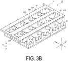
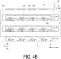
- FIGS. 3A to 4B illustrate a state in which the impact absorbing portion 12 is being switched from the retracted state to the protruding state.
- FIGS. 3A and 3B are perspective views schematically illustrating an appearance of the impact absorption device 10
- FIGS. 4A and 4B are plan views schematically illustrating the appearance of the impact absorption device 10.
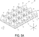
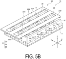
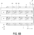
- FIGS. 5A to 6B illustrate a state in which the impact absorbing portion 12 is completely switched from the retracted state to the protruding state.
- FIGS. 5A and 5B are perspective views schematically illustrating the appearance of the impact absorption device 10
- FIGS. 6A and 6B are plan views schematically illustrating the appearance of the impact absorption device 10. Note that, in FIGS. 3A , 4A , 5A , and 6A , the top plate portion 22 is omitted for description.
- the top plate portion 22 is moved in the negative direction of the X-axis from the retracted state.
- This movement operation of the top plate portion 22 is caused by driving the top plate portion 22 in the negative direction of the X-axis by the drive unit.
- the drive unit For example, a solenoid, a motor, an electromagnet or the like is used for the drive unit, and the drive unit is connected to the connecting portion 22D on the negative side of the X-axis of the top plate portion 22 through a string or a rod.
- the top plate portion 22 moves in the negative direction of the X-axis by the drive unit pulling this string or rod in the negative direction of the X-axis.
- the top plate portion 22 is moved to rotationally drive each fin 21 in the activating direction.
- the impact absorbing member 20 to be erected is pushed up, causing the impact absorbing member 20 to rotate in the activating direction of the pivoting axis 20A.
- the impact absorbing portion 12 is switched to the protruding state. Note that the impact absorbing portion 12 is formed with a height (length in the Z-axis direction) of the impact absorbing member 20 from the base portion 11 in the protruding state being higher than that of the fin 21.
- the impact absorption device 10 includes a restricting portion 13 configured to restrict rotation in the activating direction about the pivoting axis 20A when the impact absorbing member 20 is switched from the lying posture to the standing posture.
- one impact absorbing member 20 has five pivoting axis centers (not illustrated), and a restricting portion 13 is provided for each of the arrangement positions of the pivoting axis centers. The restricting portion 13 prevents the impact absorbing member 20 in the standing posture from further rotating in the activating direction.
- the fin 21 includes an abutment portion 21B (an example of a "first abutment portion") configured to abut against the impact absorbing member 20 to be erected when the fin 21 is switched to the standing posture.
- the abutment portion 21B of the fin 21 in the second row and the first column is denoted by a reference sign, but all fins 21 include the abutment portion 21B.
- the abutment portion 21B restricts the impact absorbing member 20 in the standing posture from rotating in the standing-to-lying direction.
- the fin 21 includes an abutment portion 21C configured to abut against the impact absorbing member 20 of another column adjacent to the impact absorbing member 20 to be erected when the fin 21 is switched to the standing posture.
- the abutment portion 21C of the fin 21 in the second row and the first column is denoted by a reference sign, but at least the fins 21 in the second column and the third column each include the abutment portion 21C.
- the impact absorbing member 20 includes a groove portion 20B which suppresses interference with the abutment portion 21C of the fin 21 in the process of switching the fin 21 from the lying posture to the standing posture.
- the groove portion 20B is formed on a side surface of the impact absorbing member 20 corresponding to each abutment portion 21C.
- the groove portion 20B is formed along the movement locus of the abutment portion 21C when the fin 21 is moved.
- the abutment portion 21C of the fin 21 prevents the impact absorbing member 20 in another column adjacent to the impact absorbing member 20 to be erected by the fin 21 from being hindered in rotation by the abutment portion 21C.
- the fins 21 in the second and third columns are intermediate fins 210 arranged between the impact absorbing member 20 to be erected and the impact absorbing member 20 in another column adjacent to the impact absorbing member 20 to be erected.
- the intermediate fin 210 in the standing posture With the intermediate fin 210 in the standing posture, the impact absorbing member 20 to be erected abuts against the abutment portion 21B of the intermediate fin 210, and the impact absorbing member 20 in another column adjacent to the impact absorbing members 20 to be erected abuts against the abutment portion 21C of the intermediate fin 210.
- the intermediate fin 210 in the standing posture can support the impact absorbing members 20 to be erected and the impact absorbing members 20 in another column adjacent to the impact absorbing members 20 to be erected.
- the top plate portion 22 includes a plate-shaped portion 22E formed substantially flat.
- the plate-shaped portion 22E is a portion disposed on a front surface side of the top plate portion 22 so as to face an occupant.
- the top plate portion 22 is driven by the drive unit while maintaining the plate-shaped portion 22E parallel to the base portion 11.
- the plate-shaped portion 22E functions as a surface that receives the occupant's body.
- the plate-shaped portion 22E reduces the possibility of occupant injury. Note that the top plate portion 22 needs only at least the plate-shaped portion 22E having flexibility in order to reduce the possibility of occupant injury.
- the impact absorbing portion 12 of the impact absorption device 10 according to the present embodiment can be switched between the retracted state and the protruding state, the impact absorbing portion 12 can be maintained in the retracted state when not activated to prevent the impact absorbing portion 12 from being bulky, and the impact absorption device 10 can be arranged in a cabin or the like.
- the impact absorption device 10 according to the present embodiment can be arranged in a more flexible manner.
- the impact absorption device 10 can return to its original shape even after the top plate portion 22 receives the occupant, and can be repeatedly used because the impact absorption device 10 is switchable between the protruding state and the retracted state.
- the impact absorbing portion 12 when the drive unit activates the impact absorbing portion 12, the impact absorbing portion 12 may be switched from the retracted state to the protruding state and may be switched from the protruding state to the retracted state manually by an occupant. Alternatively, the drive unit may perform driving for switching the impact absorbing portion 12 from the protruding state to the retracted state.
- the drive unit may include an elastic member configured to bias the top plate portion 22 in the positive X-axis direction and, when switching from the protruding state to the retracted state, the top plate portion 22 may be moved in the positive X-axis direction by releasing the extension state of a string (not illustrated) attached to the top plate portion 22, to switch the impact absorbing portion 12 to the retracted state.
- drive units configured to drive the impact absorbing member 20 and the fin 21 separately may be used, or the impact absorbing member 20 and the fin 21 may be driven together by one drive unit.
- the impact absorption device 10 according to the present modified example has a configuration (structure) for preventing the impact absorbing member 20 from falling toward the retracted state when a load is applied to the impact absorbing member 20 in the protruding state.
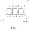
- FIG. 7 is a schematic view of the impact absorption device 10 according to the present modified example when viewed from the negative side toward the positive side of the X-axis.
- the impact absorbing member 20 and the fin 21 face each other, and the impact absorbing member 20 engages with the fin 21 by being deformed when receiving a load including a component in a direction (negative direction of the Z-axis) opposite to the front surface side of the base portion 11.
- the fin 21 includes a protruding portion 211 formed at a position facing the impact absorbing member 20 in the protruding state and protruding in either the positive or negative direction of the Y-axis. In the example illustrated in FIG.
- the protruding portion 211 is formed on both sides of the fin 21.
- the fin 21 when the fin 21 is the intermediate fin 210 illustrated in FIG. 6 , the fin 21 faces the impact absorbing members 20 in the adjacent rows on both sides in the protruding state, and the pair of protruding portions 211 formed on both sides face the impact absorbing members 20 in the adjacent columns on both sides.
- the fin 21 need only have at least the protruding portion 211 on the negative side of the Y-axis.
- the impact absorbing member 20 and the fin 21 can be set at a right angle or an angle close to a right angle with respect to the base portion 11 in the protruding state.
- the direction (first direction) in which the pivoting axis of the impact absorbing member 20 extends and the direction (second direction) in which the pivoting axis of the fin extends are orthogonal to each other.
- the impact absorbing member 20 may have greater flexibility than the fin 21 in terms of impact relieving at the time of contact with the impact absorbing member 20.
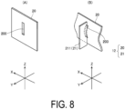
- FIGS. 8(A) and 8(B) are schematic views illustrating a portion of the impact absorbing member 20 that faces one fin 21.
- FIG. 8(A) illustrates a portion of the impact absorbing member 20 in a state in which no load is applied.
- the impact absorbing member 20 includes a groove 200 (an example of a "first groove") formed at a position facing the fin 21 in the protruding state and engageable with a portion of the fin 21.
- the groove 200 is formed into, for example, a rectangular shape having a longitudinal direction along the Z-axis, and is formed to penetrate the impact absorbing member 20.
- the groove 200 is formed with its center disposed in the Z-axis direction of the impact absorbing member 20. Note that the groove 200, as long as engageable with the fin 21, may be formed without penetrating the impact absorbing member 20.
- FIG. 8(B) is a schematic view illustrating a state in which the impact absorbing member 20 is engaged with the protruding portion 211 of the fin 21 when a load is applied to the impact absorbing member 20.
- FIG. 8(B) only the protruding portion 211 is extracted from the fin 21, and the protruding portion 211 is schematically illustrated as a rectangular plate shape.
- a height of the impact absorbing member 20 from the installation surface of the base portion 11 is higher than that of the fin 21 and thus, when a load is applied in the negative direction of the Z-axis to the impact absorbing portion 12, the impact absorbing member 20 first receives the load and deforms. As illustrated in FIG.
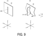
- FIGS. 9(A) and 9(B) are schematic views illustrating another example of the groove 200.
- FIGS. 9(A) and 9(B) illustrate a portion of the impact absorbing member 20 that faces one fin 21.
- FIG. 9(A) illustrates a portion of the impact absorbing member 20 in a state in which no load is applied.
- the groove 200 is formed to a length that reaches a lower portion of the impact absorbing member 20.
- the groove 200 is formed in a rectangular shape having a longitudinal direction along the Z-axis, and is formed to penetrate the impact absorbing member 20 and reach the lower portion of the impact absorbing member 20.
- FIG. 9(B) is a schematic view illustrating a state in which the impact absorbing member 20 is engaged with the protruding portion 211 of the fin 21 when a load is applied to the impact absorbing member 20.
- FIG. 9(B) only the protruding portion 211 is extracted from the fin 21, and the protruding portion 211 is schematically illustrated as a rectangular plate shape.
- FIG. 9(B) when the impact absorbing member 20 receives a load in the negative direction of the Z-axis, a portion of the impact absorbing member 20 including the groove 200 deforms toward the fin 21, engaging the groove 200 with the protruding portion 211 of the fin 21.
- the groove 200 as long as engageable with a portion of the fin 21, may be formed at any position.
- the shape of the groove 200 is not limited to a rectangular shape, and may be an oval shape (track shape), an elliptical shape, or another shape as long as the groove 200 is engageable with a portion of the fin 21.
- the fin 21 restricts rotation about the pivoting axis 21A (refer to FIG. 2A and the like) and the switching to the retracted state. Accordingly, even when a load is applied, the standing posture of the impact absorbing member 20 is maintained.
- the impact absorption device 10 according to the present modified example can prevent the impact absorbing member 20 from falling toward the retracted state when a load is applied to the impact absorbing member 20.
- the impact absorbing member 20 does not necessarily need to be in contact with the fin 21 as long as the impact absorbing member 20 is engageable with the fin 21 after the impact absorbing member 20 receives a load and deforms. Therefore, the front surface of the impact absorbing member 20 and a side surface of the fin 21 need only face each other in the protruding state of the impact absorbing portion 12. In this case, for example, the impact absorbing member 20 and the fin 21 may be driven by separate drive units. Note that the fin 21 is driven in synchronization with the impact absorbing member 20.
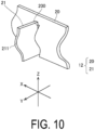
- FIG. 10 is a schematic view illustrating one fin 21 and a portion of the impact absorbing member 20 facing the fin 21.
- FIG. 10 illustrates a state in which a load is applied in the negative direction of the Z-axis to the impact absorbing member 20 and the fin 21.
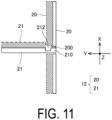
- FIG. 11 is a schematic view of the state illustrated in FIG. 10 , as viewed from above.
- a groove 212 (an example of a "second groove") is also formed in the fin 21 in addition to the groove 200 of the impact absorbing member 20.
- the impact absorbing member 20 and the fin 21 receive a load in the negative direction of the Z-axis
- the impact absorbing member 20 deforms in the positive direction of the Y-axis (an example of the "second direction being predetermined")
- the fin 21 also deforms in the positive direction of the X-axis.
- the impact absorbing member 20 and the fin 21 before deformation are indicated by solid lines
- the impact absorbing member 20 and the fin 21 after deformation are indicated by dashed lines
- the deformed portions are filled with hatching.
- the fin 21 includes the groove 212 engageable with the impact absorbing member 20 by being deformed and thus sandwiching a portion of the impact absorbing member 20 deformed into a protruding shape when receiving a load in the negative direction of the Z-axis.
- the impact absorbing member 20 partially deforms into a protruding shape in the positive direction of the Y-axis, sandwiching the fin 21.
- the fin 21 also deforms, the impact absorbing member 20 is sandwiched by the groove 212 of the fin 21.
- the groove 212 is formed in the protruding portion 211 and, before deformation, faces a side surface of the groove 200 in the groove 200 of the impact absorbing member 20.
- the impact absorbing member 20 and the fin 21 deform, the groove 212 engages with the side surface of the groove 200 in the impact absorbing member 20, causing the impact absorbing member 20 and the fin 21 to support each other.
- the impact absorbing member 20 receives a load, the impact absorbing member 20 is restricted from being switched to the retracted state.
- the impact absorption device 10 can efficiently absorb the impact received by the impact absorbing member 20.
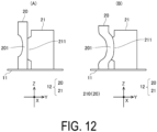
- FIGS. 12(A) and 12(B) are each a schematic view illustrating one fin 21 and a portion of the impact absorbing member 20 facing the fin 21.
- FIGS. 12(A) and 12(B) each illustrate a state in which the impact absorption device 10 is viewed from the positive side toward the negative side of the X-axis.
- FIG. 12(A) illustrates the impact absorbing member 20 in a state in which no load is applied.
- FIG. 12(B) illustrates a state in which the impact absorbing member 20 is engaged with the protruding portion 211 of the fin 21 when a load is applied to the impact absorbing member 20 from the state illustrated in FIG. 12(A) .
- the impact absorbing member 20 includes a deformation support portion 201 formed on the negative side of the Y-axis of the impact absorbing member 20, and thus preferentially deforms in the positive direction of the Y-axis when receiving a load in the negative direction of the Z-axis.
- the deformation support portion 201 is formed on the entire impact absorbing member 20 in the X-axis direction.
- the deformation support portion 201 is a thinned part formed on the side surface of the impact absorbing member 20, extending in the X-axis direction.
- the deformation support portion 201 which is a thinned part, cannot support the input load. Therefore, the impact absorbing member 20 readily deforms in the positive direction of the Y-axis, which is opposite to the side on which the deformation support portion 201 is formed.
- the fin 21 to be engaged with the impact absorbing member 20 is arranged. Therefore, the impact absorbing member 20 always deforms in the same direction after receiving a load, and readily engages with the fin 21.
- FIGS. 13(A) and 13(B) are each a schematic view illustrating one fin 21 and a portion of the impact absorbing member 20 facing the fin 21.
- FIGS. 13(A) and 13(B) each illustrate a state in which the impact absorption device 10 is viewed from the positive side toward the negative side of the X-axis.
- FIG. 13(A) illustrates the impact absorbing member 20 in a state in which no load is applied.
- FIG. 13(B) illustrates a state in which the impact absorbing member 20 is engaged with the protruding portion 211 of the fin 21 when a load is applied to the impact absorbing member 20 from the state illustrated in FIG. 13(A) .
- the impact absorbing member 20 includes a deformation support portion 202 configured to deform in advance toward the positive side of the Y-axis of the impact absorbing member 20, and thus preferentially deforms in the positive direction of the Y-axis when receiving a load in the negative direction of the Z-axis.
- the deformation support portion 202 is formed on the entire impact absorbing member 20 in the X-axis direction.
- the deformation support portion 202 is an area that extends in the X-axis direction on the side surface of the impact absorbing member 20 and is deformed in advance toward the positive side of the Y-axis. With such a deformation support portion 202 being formed on the impact absorbing member 20, the impact absorbing member can be always deformed in the positive direction of the Y-axis when a load is applied to the impact absorbing member 20.
- the deformation support portion may be formed on the fin 21.
- the deformation support portion can be formed accordingly and thus cause the fin 21 to deform in the positive direction.
- FIGS. 14(A) and 14(B) each illustrate a portion of the impact absorbing member 20 before deformation.
- FIG. 14(A) is a perspective view of the impact absorbing member 20
- FIG. 14(B) is a schematic view of the impact absorbing member 20 and the fin 21 facing the impact absorbing member 20, as viewed from above.
- a pair of projections 203 having a hemispherical shape are formed on the surface of the impact absorbing member 20 on the side facing the fin 21.
- the pair of projections 203 are arranged with a gap therebetween to such an extent that the fin 21 is engageable therebetween.
- a protruding amount of the projection 203 from the surface of the impact absorbing member 20 is set to such an extent that the engagement with the impact absorbing member 20 is not released when the fin 21 is sandwiched between the projections.
- the impact absorbing member 20 and the fin 21 are in the protruding state, an end portion of the fin 21 is positioned between the two projections 203.
- the impact absorbing member 20 does not come into contact with the fin 21 in the protruding state.
- the impact absorbing member 20 and the fin 21 are driven by separate drive units.
- FIGS. 14(C) and 14(D) each illustrate a portion of the impact absorbing member 20 after deformation.
- FIG. 14(C) is a perspective view of the impact absorbing member 20
- FIG. 14(D) is a schematic view of the impact absorbing member 20 and the fin 21 facing the impact absorbing member 20, as viewed from above.
- FIGS. 14(C) and 14(D) each illustrate a state in which a load is applied to the impact absorbing member 20 in the negative direction of the Z-axis and the impact absorbing member 20 is deformed.
- the impact absorbing member 20 which had been separated comes into contact with the fin 21, and the two projections 203 deform, sandwiching the fin 21.
- the fin 21 also starts deformation in a state of being sandwiched between the two projections.
- the two projections 203 preferably are formed at positions where the deformation amount of the impact absorbing member 20 when deformed is largest, and preferably have a hemispherical shape and thus do not hinder deformation of the impact absorbing member 20.
- the projection 203 is formed in a shape elongated in the Z-axis direction, a rigidity of the impact absorbing member 20 in the Z-axis direction increases, and the impact absorbing member 20 is less likely to deform in the Z-axis direction, which is not preferable.
- a portion of the impact absorbing member 20 deforms, approaching and coming into contact with the fin 21.
- the impact absorbing member 20 and the fin 21 are engaged. Note that, as deformation progresses, areas of the fin 21 other than the portion sandwiched between the two projections 203 may deform or may shrink.
- the impact absorbing member 20 and the fin 21 may be configured to be engageable with each other by providing the projection 203 instead of the groove to the impact absorbing member 20.
- the impact absorbing member 20 receives a load in the protruding state, the standing state of the fin 21 is maintained and the fin 21 restricts the impact absorbing member 20 from switching to the retracted state.
- FIG. 15 is a block diagram including a vehicle 100 in which the impact absorption device 10 is disposed. In the present embodiment, a plurality of the impact absorption devices 10 are mounted in the vehicle.
- the impact absorption devices 10 may be arranged in a quantity equivalent to a maximum number of occupants of the vehicle 100, and may be arranged one per occupant.
- FIG. 15 illustrates four impact absorption devices 10 and representatively illustrates the function units of one impact absorption device 10.
- the impact absorption device 10 includes a control unit 101.
- the control unit 101 is constituted by, for example, a microcomputer, and executes each processing by causing a central processing unit (CPU; not illustrated) to execute a program stored in a storage means (read only memory (ROM)) or the like; not illustrated).
- CPU central processing unit
- ROM read only memory
- FIG. 15 illustrates a sensor 103, a positional information acquisition unit 104, a travel control unit 105, and a travel drive unit 106, which are mounted on the vehicle 100.
- the vehicle 100 is capable of automatic driving on a road in an appropriate manner as autonomous traveling while sensing its surroundings. Note that the vehicle 100 can of course be manually operated by a passenger.
- the sensor 103 is a means for sensing the surroundings of the vehicle 100 in order to acquire information necessary for autonomous traveling of the vehicle 100, and typically includes a stereo camera, a laser scanner, a LIDAR, various radars, or the like.
- the information acquired by the sensor 103 is transmitted to the travel control unit 105, and is used by the travel control unit 105 to recognize obstacles, pedestrians, and traffic lanes existing around the vehicle 100 and the like.
- the sensor 103 may include a visible light camera or an infrared camera for monitoring.
- the positional information acquisition unit 104 is a means for acquiring the current position of the vehicle 100, and typically includes a GPS receiver or the like.
- the information acquired by the positional information acquisition unit 104 is also transmitted to the travel control unit 105, and is used for predetermined processing such as, for example, the calculation of a route for the vehicle 100 to reach a destination by using the current position of the vehicle 100 and the calculation of a required time for reaching the destination.
- the travel control unit 105 is a computer that controls the vehicle 100 based on information acquired from the sensor 103 and the positional information acquisition unit 104.
- the travel control unit 105 is constituted by, for example, a microcomputer, and achieves functions for performing various processes described above by causing a central processing unit (CPU; not illustrated) to execute a program stored in a storage means (read only memory (ROM) or the like; not illustrated).
- CPU central processing unit
- ROM read only memory
- a specific example of various processing by the travel control unit 105 includes processing such as: processing of generating a travel plan for the vehicle 100; processing of detecting predetermined data around the vehicle 100 necessary for autonomous driving, based on data acquired by the sensor 103; and processing of generating a control command for controlling autonomous traveling, based on a travel plan, predetermined data, and the position information of the vehicle 100 acquired by the positional information acquisition unit 104.
- the processing of generating a travel plan is processing of determining a travel route from a starting point to a destination.
- the processing of detecting predetermined data is processing for detecting, for example, the number and position of lanes, the number and position of other vehicles existing around the vehicle 100, the number and position of obstacles (e.g., pedestrians, bicycles, structures, buildings, or the like) existing around the vehicle 100, the structure of a road, a road sign, or the like.
- the control command is transmitted to the travel drive unit 106 described below.
- a known method may be employed for generating a control command for autonomous traveling of the vehicle 100.
- the travel drive unit 106 is a means for driving the vehicle 100 based on a control command generated by the travel control unit 105.
- the travel drive unit 106 includes, for example, a motor for driving wheels, an engine, an inverter, a brake, a steering mechanism, or the like, and the motor, the brake, or the like are driven in accordance with a control command to achieve autonomous traveling of the vehicle 100.
- FIG. 16 is a flowchart of the processing performed by the control unit 101. Note that this processing is repeatedly executed at predetermined intervals by the control unit 101.
- the control unit 101 acquires various types of information. Various types of information are transmitted from the travel control unit 105.
- control unit 101 determines whether drive control is required.
- the control unit 101 when determining that the information indicating that the vehicle 100 has been rapidly decelerated is included in the various types of information acquired in S101, determines that drive control is necessary.
- the control unit 101 when determining that the drive control is necessary in S102, executes the processing in S103.
- the control unit 101 executes drive control.
- the drive unit 102 includes a solenoid, a motor, an electromagnet, or the like to drive the top plate portion 22.
- the impact absorption device 10 can switch the impact absorbing portion 12 from the retracted state to the protruding state. Note that the impact absorbing member 20 and the fin 21 may be separately driven in synchronization with each other.
- the top plate portion 22 is integrally formed by connecting the coupling portions 22A, 22B, 22C to each other by the connecting portions 22D, but the coupling portions 22A, 22B, 22C are not connected to each other and the respective coupling portions 22A, 22B, 22C may be driven by the drive unit.
- the impact absorption device 10 includes a plurality of driving force transmitting members. Note that the drive unit may drive the fin 21 without providing the driving force transmitting member.
- the impact absorption device 10 can be activated to avoid collision between the occupant and the vehicle components due to sudden braking of the vehicle even when the vehicle does not result in collision.
- the impact absorption device 10 can be activated every time the vehicle is suddenly braked.
- the impact absorption device 10 can be attached to any part of the vehicle.
- the impact absorption device 10 is attached on a dashboard lower panel covering a steering column shaft to protect an occupant seated in a driver's seat, on the back of a front seat back to protect a passenger seated in a rear seat, or inside a seat back to prevent a submarine phenomenon of an occupant seated in a seat, or the like.
- These impact absorption devices may also be attached outside the vehicle to protect the occupants of the vehicle in the event of a collision between the vehicle and roadside obstacles or other vehicles.
- the impact absorption device 10 may be attached to a device other than the vehicle.
- the impact absorption device 10 may be attached to a robot to protect the robot.
- the impact absorption device 10 may also be attached to a jacket to protect a wearer of the jacket in the event that the wearer falls.
Landscapes
- Engineering & Computer Science (AREA)
- Mechanical Engineering (AREA)
- General Engineering & Computer Science (AREA)
- Vibration Dampers (AREA)
Abstract
Description
- The present disclosure relates to an impact absorption device that relieves an impact when activated.
- In the related art, a technology for relieving an impact caused by an accident or the like is known. For example,
Patent Document 1 describes an energy absorber for protecting a pedestrian or the like colliding with a bumper of a vehicle by relieving an impact generated on the bumper of the vehicle. In this energy absorber, respective gaps between a plurality of fins connected to a base and absorbing an impact are formed. - Patent Document 1:
US 10,046,723 - In an impact absorption device, a region where an impact absorbing member can flex needs to be formed. For example, in the energy absorber described in
Patent Document 1, the respective gaps between the plurality of fins correspond to such a region. The impact absorption device has a bulky structure as a whole when this region is formed, and thus the position of the impact absorption device to be mounted on the vehicle is limited, and a degree of freedom of an arrangement position thereof is reduced. - In view of the problems described above, an object of the present disclosure is to provide an impact absorption device capable of improving a degree of freedom of an arrangement position thereof.
- To solve the problems described above, the present disclosure adopts the following configuration.
- An impact absorption device configured to relieve an impact when activated includes an impact absorbing member, an auxiliary member, and a drive unit. The impact absorbing member has flexibility and is attached to a base portion in a manner reversibly switchable between a retracted state in which the impact absorbing member is retracted toward an installation surface of the base portion and a protruding state in which the impact absorbing member protrudes from the installation surface. The auxiliary member has flexibility and is attached to the base portion in a manner reversibly switchable between a retracted state in which the auxiliary member is retracted toward the installation surface and a protruding state in which the auxiliary member protrudes from the installation surface in synchronization with the retracted state and the protruding state of the impact absorbing member. The drive unit is configured to directly or indirectly drive the impact absorbing member when the impact absorbing member and the auxiliary member are activated, thereby switching the impact absorbing member at least from the retracted state to the protruding state. The impact absorbing member is attached to the installation surface of the base portion rotatably about a first pivoting axis extending in a first direction, and is reversibly switched between the retracted state and the protruding state by being rotationally driven about the first pivoting axis. The auxiliary member is attached to the installation surface rotatably about a second pivoting axis extending in a second direction intersecting the first direction, and is reversibly switched between the retracted state and the protruding state by being rotationally driven about the second pivoting axis. A height of the impact absorbing member from the base portion in the protruding state is higher than that of the auxiliary member. In the protruding state, at least a portion of the impact absorbing member and at least a portion of the auxiliary member face each other, and the impact absorbing member deforms when receiving a load including a component in a direction opposite to the installation surface side of the base portion, thereby engaging with the auxiliary member.
- In the impact absorption device described above, the auxiliary member may restrict the impact absorbing member from rotating about the first pivoting axis and switching to the retracted state when the impact absorbing member receives the load in the protruding state.
- In the impact absorption device described above, the impact absorbing member may include a first groove formed at a position facing the auxiliary member in the protruding state and engageable with a portion of the auxiliary member, and at least a portion of the impact absorbing member may deform toward the auxiliary member when the impact absorbing member receives the load, thereby causing the first groove to engage with a portion of the auxiliary member.
- In the impact absorption device described above, the auxiliary member may include a protruding portion formed at a position facing the first groove in the protruding state and protruding in the second direction, and the auxiliary member may deform in the first direction when the auxiliary member receives the load, thereby causing the protruding portion to engage with the first groove.
- In the impact absorption device described above, a portion of the impact absorbing member may deform into a protruding shape in the second direction when the impact absorbing member receives the load, the second direction being predetermined, and the auxiliary member may include a second groove engageable with the impact absorbing member by being deformed and sandwiching the portion of the impact absorbing member deformed into the protruding shape when receiving the load.
- In the impact absorption device described above, the impact absorbing member may include a deformation support portion formed in the first direction, causing deformation to preferentially occur in the second direction when the impact absorbing member receives the load.
- In the impact absorption device described above, the impact absorbing member may have greater flexibility than that of the auxiliary member.
- In the impact absorption device described above, the impact absorbing member may include a plurality of impact absorbing members disposed in a plurality of columns, the plurality of impact absorbing members being spaced apart in a direction orthogonal to the first direction, and each of the plurality of impact absorbing members provided in the plurality of columns may be maintained in a lying posture along the installation surface in the retracted state, rotationally driven in a predetermined activating direction about the first pivoting axis and switched from the lying posture to a standing posture in which the impact absorbing member is erected from the installation surface, when being switched from the retracted state to the protruding state, and rotationally driven in a standing-to-lying direction opposite to the activating direction about the first pivoting axis and switched from the standing posture to the lying posture, when being switched from the protruding state to the retracted state.
- In the impact absorption device described above, the auxiliary member may be disposed between each column of the plurality of impact absorbing members of the plurality of columns, maintained in a lying posture along the installation surface in the retracted state, with a portion of an impact absorbing member of the plurality of impact absorbing members in an adjacent column covering, from above, at least a portion of the auxiliary member, rotationally driven in a predetermined activating direction about the second pivoting axis and switched from the lying posture to a standing posture, when being switched from the retracted state to the protruding state, and rotationally driven in the standing-to-lying direction opposite to the activating direction about the second pivoting axis and switched from the standing posture to the lying posture, when being switched from the protruding state to the retracted state.
- In the impact absorption device described above, the auxiliary member may face, of the plurality of impact absorbing members, impact absorbing members in adjacent columns on both sides, in the protruding state.
- The impact absorption device described above may further include one or more driving force transmitting members coupled to the auxiliary member, at least partially having flexibility, and driven by the drive unit, and the one or more driving force transmitting members may be driven when the drive unit activates the impact absorbing member, thereby causing the auxiliary member to switch from the lying posture to the standing posture, and the impact absorbing member to switch from the lying posture to the standing posture, accompanying the auxiliary member.
- The impact absorption device described above may include a plurality of the auxiliary members and one of the driving force transmitting members, and the plurality of auxiliary members may be coupled to the driving force transmitting member.
- In the impact absorption device described above, the one or more driving force transmitting members may each include a plate-shaped portion and may be driven by the drive unit while maintaining a state in which the plate-shaped portion is parallel to the installation surface.
- In the impact absorption device described above, the first direction and the second direction may be orthogonal to each other.
- According to the technique of the present disclosure, a degree of freedom of an arrangement position of the impact absorption device can be improved.
-
-
FIG. 1A is an external perspective view (part 1) schematically illustrating an impact absorption device according to a first embodiment. -
FIG. 1B is an external perspective view (part 2) schematically illustrating the impact absorption device according to the first embodiment. -
FIG. 2A is a plan view (part 1) schematically illustrating the impact absorption device according to the first embodiment. -
FIG. 2B is a plan view (part 2) schematically illustrating the impact absorption device according to the first embodiment. -
FIG. 3A is an external perspective view (part 3) schematically illustrating the impact absorption device according to the first embodiment. -
FIG. 3B is an external perspective view (part 4) schematically illustrating the impact absorption device according to the first embodiment. -
FIG. 4A is a plan view (part 3) schematically illustrating the impact absorption device according to the first embodiment. -
FIG. 4B is a plan view (part 4) schematically illustrating the impact absorption device according to the first embodiment. -
FIG. 5A is an external perspective view (part 5) schematically illustrating the impact absorption device according to the first embodiment. -
FIG. 5B is an external perspective view (part 6) schematically illustrating the impact absorption device according to the first embodiment. -
FIG. 6A is a plan view (part 5) schematically illustrating the impact absorption device according to the first embodiment. -
FIG. 6B is a plan view (part 6) schematically illustrating the impact absorption device according to the first embodiment. -
FIG. 7 is a schematic view (part 1) illustrating an example of an impact absorbing member and a fin of the impact absorption device according to a modified example of the first embodiment. -
FIG. 8 is a schematic view (part 2) illustrating an example of the impact absorbing member and the fin of the impact absorption device according to a modified example of the first embodiment. -
FIG. 9 is a schematic view (part 3) illustrating an example of the impact absorbing member and the fin of the impact absorption device according to a modified example of the first embodiment. -
FIG. 10 is a schematic view (part 4) illustrating an example of the impact absorbing member and the fin of the impact absorption device according to a modified example of the first embodiment. -
FIG. 11 is a schematic view (part 5) illustrating an example of the impact absorbing member and the fin of the impact absorption device according to a modified example of the first embodiment. -
FIG. 12 is a schematic view (part 6) illustrating an example of the impact absorbing member and the fin of the impact absorption device according to a modified example of the first embodiment. -
FIG. 13 is a schematic view (part 7) illustrating an example of the impact absorbing member and the fin of the impact absorption device according to a modified example of the first embodiment. -
FIG. 14 is a schematic view (part 8) illustrating an example of the impact absorbing member and the fin of the impact absorption device according to a modified example of the first embodiment. -
FIG. 15 is a block diagram of the impact absorption device according to the first embodiment. -
FIG. 16 is a flowchart of processing executed by a control unit of the impact absorption device according to the first embodiment. - Hereinafter, an impact absorption device according to an embodiment of the present disclosure will be described with reference to the drawings. Note that the respective configurations, the combinations thereof, and the like in the respective embodiments are only examples, and the configurations may be added, omitted, substituted, or otherwise modified as appropriate within a scope that does not depart from the spirit of the present disclosure. The present disclosure is not limited by the embodiments and is limited only by the claims.
- An impact absorption device according to a first embodiment will now be described. The impact absorption device according to the present embodiment is mounted on a vehicle such as an automobile, and is exemplified as a device for protecting an occupant in the vehicle. The impact absorption device is attached to an attachment target which constitutes the vehicle and protects the occupant when activated. Note that examples of the attachment target which constitutes the vehicle include a structure which constitutes the vehicle body such as a pillar or a ceiling, and a structure which constitutes the vehicle body such as a dashboard or a steering wheel. The impact absorption device is fixed to the vehicle by being attached to such an attachment target. Note that a base portion itself may be the attachment target itself, or an
impact absorbing portion 12 or the like described below may be directly provided to the attachment target. - Next, an
impact absorption device 10 according to the present embodiment will be described in detail with reference toFIGS. 1A to 2B .FIGS. 1A and1B are perspective views schematically illustrating an appearance of theimpact absorption device 10 according to the present embodiment.FIGS. 2A and2B are plan views schematically illustrating the appearance of theimpact absorption device 10 according to the present embodiment. Theimpact absorption device 10 includes abase portion 11 attached to an attachment target of a vehicle, and theimpact absorbing portion 12 attached to a front surface (an example of an "installation surface") side of thebase portion 11. Thebase portion 11 has a rectangular plate-like shape, and theimpact absorbing portion 12 is arranged on the front surface side of thebase portion 11, and a back surface side thereof is attached to an attachment target. Hereinafter, as illustrated inFIGS. 1A to 2B , a direction along a long side of thebase portion 11 is defined as an X-axis, a direction along a short side of thebase portion 11 is defined as a Y-axis, and a direction orthogonal to both the X-axis and the Y-axis (direction orthogonal to the front surface and the back surface of the base portion) is defined as a Z-axis. Theimpact absorption device 10 is a device for protecting an occupant to be protected and positioned in the Z-axis direction. Note that the direction along the X-axis is defined as a "row" of the matrix, and the direction along the Y-axis is defined as a "column" of the matrix. - The
impact absorbing portion 12 has flexibility as a whole, and absorbs a force (load) applied to an occupant by deforming when an accident or the like occurs in a vehicle and an inertial force is generated on the occupant, causing the occupant to collide with theimpact absorbing portion 12. Thus, theimpact absorbing portion 12 relieves the impact on the occupant and protects the occupant. Theimpact absorbing portion 12 is configured to protrude toward a cabin occupied by the occupant. More specifically, theimpact absorbing portion 12 is configured to be reversibly switchable between a retracted state in which theimpact absorbing portion 12 is retracted from the cabin toward thebase portion 11 and a protruding state in which theimpact absorbing portion 12 protrudes from thebase portion 11 toward the cabin. In the state illustrated inFIGS. 1A to 2B , theimpact absorbing portion 12 is in the retracted state. - The
impact absorbing portion 12 includes animpact absorbing member 20, a fin 21 (an example of an "auxiliary member"), and a top plate portion 22 (an example of a "driving force transmitting member"). Note that, inFIGS. 1A and2A , thetop plate portion 22 is not illustrated for description. - The
impact absorbing member 20 is formed of rubber or the like and has deformable flexibility such as elasticity. Theimpact absorbing member 20 has a shape in which the direction in the X-axis direction is a longitudinal direction (shape extending integrally in the X-axis direction), and threeimpact absorbing members 20 are arranged in three columns in the Y-axis direction. Theimpact absorbing member 20 is attached to the front surface side of thebase portion 11 rotatably about a pivotingaxis 20A (an example of a "first pivoting axis") extending in a direction (an example of a "first direction") along the X-axis with respect to the front surface of thebase portion 11. InFIGS. 1A and2A , the pivotingaxis 20A is represented by a dashed line.Respective pivoting axes 20A of the threeimpact absorbing members 20 are spaced apart from each other in a direction along the Y-axis (an example of a "second direction"), making it possible for eachimpact absorbing member 20 to operate without interfering with each other. Note that, hereinafter, three impact absorbing members provided in three columns may be referred to as a plurality of columns ofimpact absorbing members 20. Thus, theimpact absorbing portion 12 includes the plurality of columns ofimpact absorbing members 20. - Each of the plurality of columns of
impact absorbing members 20 is maintained in a lying posture along the front surface of thebase portion 11 in the retracted state, as illustrated inFIG. 1A . Each of the plurality of columns ofimpact absorbing members 20 is rotationally driven in an activating direction about the pivotingaxis 20A when being switched from the retracted state to the protruding state, and thus switches from the lying posture to a standing posture in which theimpact absorbing member 20 is erected from the front surface of thebase portion 11. The activating direction of theimpact absorbing member 20 is clockwise when viewed toward the positive direction of the X-axis. When being switched from the protruding state to the retracted state, each of the plurality of columns ofimpact absorbing members 20 is rotationally driven in a standing-to-lying direction opposite to the activating direction about the pivotingaxis 20A and thus switches from the standing posture to the lying posture. The standing-to-lying direction of theimpact absorbing member 20 is counterclockwise when viewed toward the positive direction of the X-axis. As described above, each of the plurality of columns ofimpact absorbing members 20 is configured to be reversibly switchable between the retracted state and the protruding state. - The
fin 21 is formed of rubber or the like and has deformable flexibility such as elasticity. Thefin 21 erects theimpact absorbing member 20 by transmitting power from a drive unit to theimpact absorbing member 20. The drive unit can drive theimpact absorbing member 20 indirectly by driving thefin 21. In the present embodiment, fourfins 21 are arranged for oneimpact absorbing member 20. That is, a total of twelvefins 21 are arranged in four rows in the direction along the X-axis and in three columns in the direction along the Y-axis. A plurality of thefins 21 are attached to the front surface of thebase portion 11 about a pivotingaxis 21A (an example of a "second pivoting axis") that intersects the pivotingaxis 20A. InFIG. 2A , the pivotingaxis 21A of thefin 21 in the second row and the first column is indicated by a dashed line. Note that the pivoting axes 21A of the fins are parallel to each other. The plurality offins 21 are rotatable about therespective pivoting axes 21A. - In the retracted state, each of the plurality of
fins 21 is maintained in a lying posture along the front surface of thebase portion 11, with a portion of theimpact absorbing member 20 to be erected covering at least a portion of thefin 21 from above. Note that each of the plurality offins 21 erects theimpact absorbing member 20 arranged in the same column. Each of the plurality offins 21, when being switched from the retracted state to the protruding state, is rotationally driven in an activating direction about the pivotingaxis 21A and thus switches from the lying posture to a standing posture. The activating direction of thefin 21 is counterclockwise when viewed toward the positive direction of the Y-axis. Each of the plurality offins 21, when being switched from the protruding state to the retracted state, is rotationally driven in a standing-to-lying direction opposite to the activating direction about the pivotingaxis 21A and thus switches from the standing posture to the lying posture. The standing-to-lying direction of thefin 21 is clockwise when viewed toward the positive direction of the Y-axis. When thefin 21 is switched from the lying posture to the standing posture, theimpact absorbing member 20 to be erected is pushed up, making it possible to rotate theimpact absorbing member 20 in the activating direction of the pivotingaxis 20A. Note that the angle formed by the pivotingaxis 20A of theimpact absorbing member 20 and the pivotingaxis 21A of thefin 21 is preferably an acute angle, not a right angle. Note that thefin 21 can be reversibly switched between the retracted state and the protruding state in synchronization with the retracted state and the protruding state of theimpact absorbing member 20. - The
top plate portion 22 illustrated inFIGS. 1B and2B is made of rubber or the like and has flexibility. Thetop plate portion 22 is provided to transmit power from the drive unit to eachfin 21 by being driven by the drive unit. Thetop plate portion 22 includescoupling portions 22A to 22C, each coupled to thefins 21 in the same column, that is, thefins 21 for erecting the sameimpact absorbing member 20. Each of thecoupling portions 22A to 22C has a shape having a longitudinal direction along the X-axis. Thecoupling portion 22A is coupled to thefins 21 in the first column. Thecoupling portion 22B is coupled to thefins 21 in the second column. Thecoupling portion 22C is coupled to thefins 21 in the third column. Thus, thetop plate portion 22 is coupled to allfins 21. - The
top plate portion 22 includes a pair of connectingportions 22D which connect and integrate therespective coupling portions 22A to 22C. The connectingportions 22D connect therespective coupling portions 22A to 22C at both ends in the direction along the X-axis. Thus, thetop plate portion 22 can transmit the power of the drive unit to all thefins 21. In this way, in the present embodiment, theimpact absorbing portion 12 includes a singletop plate portion 22 in which thecoupling portions portions 22D are integrally formed. - When the drive unit of the
impact absorption device 10 activates theimpact absorbing portion 12, thetop plate portion 22 is driven to switch thefins 21 from the lying posture to the standing posture, and eachimpact absorbing member 20 is switched from the lying posture to the standing posture accompanying thefins 21. Thus, theimpact absorption device 10 according to the present embodiment can switch theimpact absorbing portion 12 from the retracted state to the protruding state when theimpact absorbing portion 12 is activated by the drive unit. - Next, the operation of the
impact absorption device 10 according to the present embodiment will be described with reference toFIGS. 3A to 6B .FIGS. 3A to 4B illustrate a state in which theimpact absorbing portion 12 is being switched from the retracted state to the protruding state.FIGS. 3A and3B are perspective views schematically illustrating an appearance of theimpact absorption device 10, andFIGS. 4A and4B are plan views schematically illustrating the appearance of theimpact absorption device 10.FIGS. 5A to 6B illustrate a state in which theimpact absorbing portion 12 is completely switched from the retracted state to the protruding state.FIGS. 5A and5B are perspective views schematically illustrating the appearance of theimpact absorption device 10, andFIGS. 6A and6B are plan views schematically illustrating the appearance of theimpact absorption device 10. Note that, inFIGS. 3A ,4A ,5A , and6A , thetop plate portion 22 is omitted for description. - As illustrated in
FIGS. 3B and4B , thetop plate portion 22 is moved in the negative direction of the X-axis from the retracted state. This movement operation of thetop plate portion 22 is caused by driving thetop plate portion 22 in the negative direction of the X-axis by the drive unit. For example, a solenoid, a motor, an electromagnet or the like is used for the drive unit, and the drive unit is connected to the connectingportion 22D on the negative side of the X-axis of thetop plate portion 22 through a string or a rod. Thetop plate portion 22 moves in the negative direction of the X-axis by the drive unit pulling this string or rod in the negative direction of the X-axis. Thetop plate portion 22 is moved to rotationally drive eachfin 21 in the activating direction. With thefin 21 being rotationally driven in the activating direction, theimpact absorbing member 20 to be erected is pushed up, causing theimpact absorbing member 20 to rotate in the activating direction of the pivotingaxis 20A. As illustrated inFIGS. 5A to 6B , with theimpact absorbing members 20 and thefins 21 being brought to the standing posture, theimpact absorbing portion 12 is switched to the protruding state. Note that theimpact absorbing portion 12 is formed with a height (length in the Z-axis direction) of theimpact absorbing member 20 from thebase portion 11 in the protruding state being higher than that of thefin 21. - As illustrated in
FIG. 5A , theimpact absorption device 10 according to the present embodiment includes a restrictingportion 13 configured to restrict rotation in the activating direction about the pivotingaxis 20A when theimpact absorbing member 20 is switched from the lying posture to the standing posture. In the present embodiment, oneimpact absorbing member 20 has five pivoting axis centers (not illustrated), and a restrictingportion 13 is provided for each of the arrangement positions of the pivoting axis centers. The restrictingportion 13 prevents theimpact absorbing member 20 in the standing posture from further rotating in the activating direction. - Further, as illustrated in
FIG. 6A , thefin 21 includes anabutment portion 21B (an example of a "first abutment portion") configured to abut against theimpact absorbing member 20 to be erected when thefin 21 is switched to the standing posture. InFIG. 6A , theabutment portion 21B of thefin 21 in the second row and the first column is denoted by a reference sign, but allfins 21 include theabutment portion 21B. Theabutment portion 21B restricts theimpact absorbing member 20 in the standing posture from rotating in the standing-to-lying direction. - As illustrated in
FIGS. 4A and6A , thefin 21 includes anabutment portion 21C configured to abut against theimpact absorbing member 20 of another column adjacent to theimpact absorbing member 20 to be erected when thefin 21 is switched to the standing posture. InFIG. 6A , theabutment portion 21C of thefin 21 in the second row and the first column is denoted by a reference sign, but at least thefins 21 in the second column and the third column each include theabutment portion 21C. - Further, as illustrated in
FIGS. 4A and6A , theimpact absorbing member 20 includes agroove portion 20B which suppresses interference with theabutment portion 21C of thefin 21 in the process of switching thefin 21 from the lying posture to the standing posture. Thegroove portion 20B is formed on a side surface of theimpact absorbing member 20 corresponding to eachabutment portion 21C. Thegroove portion 20B is formed along the movement locus of theabutment portion 21C when thefin 21 is moved. Thus, theabutment portion 21C of thefin 21 prevents theimpact absorbing member 20 in another column adjacent to theimpact absorbing member 20 to be erected by thefin 21 from being hindered in rotation by theabutment portion 21C. - As illustrated in
FIG. 6A , thefins 21 in the second and third columns areintermediate fins 210 arranged between theimpact absorbing member 20 to be erected and theimpact absorbing member 20 in another column adjacent to theimpact absorbing member 20 to be erected. With theintermediate fin 210 in the standing posture, theimpact absorbing member 20 to be erected abuts against theabutment portion 21B of theintermediate fin 210, and theimpact absorbing member 20 in another column adjacent to theimpact absorbing members 20 to be erected abuts against theabutment portion 21C of theintermediate fin 210. Thus, theintermediate fin 210 in the standing posture can support theimpact absorbing members 20 to be erected and theimpact absorbing members 20 in another column adjacent to theimpact absorbing members 20 to be erected. - As illustrated in
FIGS. 2B ,4B , and6B , thetop plate portion 22 includes a plate-shapedportion 22E formed substantially flat. The plate-shapedportion 22E is a portion disposed on a front surface side of thetop plate portion 22 so as to face an occupant. Thetop plate portion 22 is driven by the drive unit while maintaining the plate-shapedportion 22E parallel to thebase portion 11. The plate-shapedportion 22E functions as a surface that receives the occupant's body. The plate-shapedportion 22E reduces the possibility of occupant injury. Note that thetop plate portion 22 needs only at least the plate-shapedportion 22E having flexibility in order to reduce the possibility of occupant injury. - As described above, since the
impact absorbing portion 12 of theimpact absorption device 10 according to the present embodiment can be switched between the retracted state and the protruding state, theimpact absorbing portion 12 can be maintained in the retracted state when not activated to prevent theimpact absorbing portion 12 from being bulky, and theimpact absorption device 10 can be arranged in a cabin or the like. Thus, theimpact absorption device 10 according to the present embodiment can be arranged in a more flexible manner. Further, since theimpact absorbing portion 12 has flexibility, theimpact absorption device 10 can return to its original shape even after thetop plate portion 22 receives the occupant, and can be repeatedly used because theimpact absorption device 10 is switchable between the protruding state and the retracted state. Note that, in theimpact absorption device 10, when the drive unit activates theimpact absorbing portion 12, theimpact absorbing portion 12 may be switched from the retracted state to the protruding state and may be switched from the protruding state to the retracted state manually by an occupant. Alternatively, the drive unit may perform driving for switching theimpact absorbing portion 12 from the protruding state to the retracted state. For example, the drive unit may include an elastic member configured to bias thetop plate portion 22 in the positive X-axis direction and, when switching from the protruding state to the retracted state, thetop plate portion 22 may be moved in the positive X-axis direction by releasing the extension state of a string (not illustrated) attached to thetop plate portion 22, to switch theimpact absorbing portion 12 to the retracted state. Further, drive units configured to drive theimpact absorbing member 20 and thefin 21 separately may be used, or theimpact absorbing member 20 and thefin 21 may be driven together by one drive unit. - Next, the
impact absorption device 10 according to the present embodiment will be described. Theimpact absorption device 10 according to the present modified example has a configuration (structure) for preventing theimpact absorbing member 20 from falling toward the retracted state when a load is applied to theimpact absorbing member 20 in the protruding state. -
FIG. 7 is a schematic view of theimpact absorption device 10 according to the present modified example when viewed from the negative side toward the positive side of the X-axis. In the protruding state of theimpact absorbing portion 12, theimpact absorbing member 20 and thefin 21 face each other, and theimpact absorbing member 20 engages with thefin 21 by being deformed when receiving a load including a component in a direction (negative direction of the Z-axis) opposite to the front surface side of thebase portion 11. Thefin 21 includes a protrudingportion 211 formed at a position facing theimpact absorbing member 20 in the protruding state and protruding in either the positive or negative direction of the Y-axis. In the example illustrated inFIG. 7 , the protrudingportion 211 is formed on both sides of thefin 21. For example, when thefin 21 is theintermediate fin 210 illustrated inFIG. 6 , thefin 21 faces theimpact absorbing members 20 in the adjacent rows on both sides in the protruding state, and the pair of protrudingportions 211 formed on both sides face theimpact absorbing members 20 in the adjacent columns on both sides. Note that thefin 21 need only have at least the protrudingportion 211 on the negative side of the Y-axis. Further, theimpact absorbing member 20 and thefin 21 can be set at a right angle or an angle close to a right angle with respect to thebase portion 11 in the protruding state. In the present modified example, preferably the direction (first direction) in which the pivoting axis of theimpact absorbing member 20 extends and the direction (second direction) in which the pivoting axis of the fin extends are orthogonal to each other. In addition, considering that theimpact absorbing member 20 first deforms when receiving an impact, theimpact absorbing member 20 may have greater flexibility than thefin 21 in terms of impact relieving at the time of contact with theimpact absorbing member 20. -
FIGS. 8(A) and 8(B) are schematic views illustrating a portion of theimpact absorbing member 20 that faces onefin 21.FIG. 8(A) illustrates a portion of theimpact absorbing member 20 in a state in which no load is applied. Theimpact absorbing member 20 includes a groove 200 (an example of a "first groove") formed at a position facing thefin 21 in the protruding state and engageable with a portion of thefin 21. Thegroove 200 is formed into, for example, a rectangular shape having a longitudinal direction along the Z-axis, and is formed to penetrate theimpact absorbing member 20. In the example illustrated inFIG. 8(A) , thegroove 200 is formed with its center disposed in the Z-axis direction of theimpact absorbing member 20. Note that thegroove 200, as long as engageable with thefin 21, may be formed without penetrating theimpact absorbing member 20. -
FIG. 8(B) is a schematic view illustrating a state in which theimpact absorbing member 20 is engaged with the protrudingportion 211 of thefin 21 when a load is applied to theimpact absorbing member 20. InFIG. 8(B) , only the protrudingportion 211 is extracted from thefin 21, and the protrudingportion 211 is schematically illustrated as a rectangular plate shape. A height of theimpact absorbing member 20 from the installation surface of thebase portion 11 is higher than that of thefin 21 and thus, when a load is applied in the negative direction of the Z-axis to theimpact absorbing portion 12, theimpact absorbing member 20 first receives the load and deforms. As illustrated inFIG. 8(B) , when theimpact absorbing member 20 receives a load in the negative direction of the Z-axis, a portion of theimpact absorbing member 20 including thegroove 200 deforms toward thefin 21, engaging thegroove 200 with the protrudingportion 211 of thefin 21. Accordingly, when theimpact absorbing member 20 receives a load in the protruding state, thefin 21 restricts the rotation about the pivotingaxis 21A (refer toFIG. 2A and the like) and the switching to the retracted state. Therefore, even when a load is applied, the standing posture of theimpact absorbing member 20 is maintained. Note that thegroove 200 need only be engaged with a portion of thefin 21, and thefin 21 need not be provided with the protrudingportion 211. -
FIGS. 9(A) and 9(B) are schematic views illustrating another example of thegroove 200. As inFIGS. 8(A) and 8(B) ,FIGS. 9(A) and 9(B) illustrate a portion of theimpact absorbing member 20 that faces onefin 21.FIG. 9(A) illustrates a portion of theimpact absorbing member 20 in a state in which no load is applied. In this example, thegroove 200 is formed to a length that reaches a lower portion of theimpact absorbing member 20. Thegroove 200 is formed in a rectangular shape having a longitudinal direction along the Z-axis, and is formed to penetrate theimpact absorbing member 20 and reach the lower portion of theimpact absorbing member 20. -
FIG. 9(B) is a schematic view illustrating a state in which theimpact absorbing member 20 is engaged with the protrudingportion 211 of thefin 21 when a load is applied to theimpact absorbing member 20. InFIG. 9(B) , only the protrudingportion 211 is extracted from thefin 21, and the protrudingportion 211 is schematically illustrated as a rectangular plate shape. As illustrated inFIG. 9(B) , when theimpact absorbing member 20 receives a load in the negative direction of the Z-axis, a portion of theimpact absorbing member 20 including thegroove 200 deforms toward thefin 21, engaging thegroove 200 with the protrudingportion 211 of thefin 21. As described above, thegroove 200, as long as engageable with a portion of thefin 21, may be formed at any position. Note that the shape of thegroove 200 is not limited to a rectangular shape, and may be an oval shape (track shape), an elliptical shape, or another shape as long as thegroove 200 is engageable with a portion of thefin 21. - Thus, when the
impact absorbing member 20 receives a load in the protruding state, thefin 21 restricts rotation about the pivotingaxis 21A (refer toFIG. 2A and the like) and the switching to the retracted state. Accordingly, even when a load is applied, the standing posture of theimpact absorbing member 20 is maintained. Theimpact absorption device 10 according to the present modified example can prevent theimpact absorbing member 20 from falling toward the retracted state when a load is applied to theimpact absorbing member 20. Note that, in the protruding state of theimpact absorbing portion 12, theimpact absorbing member 20 does not necessarily need to be in contact with thefin 21 as long as theimpact absorbing member 20 is engageable with thefin 21 after theimpact absorbing member 20 receives a load and deforms. Therefore, the front surface of theimpact absorbing member 20 and a side surface of thefin 21 need only face each other in the protruding state of theimpact absorbing portion 12. In this case, for example, theimpact absorbing member 20 and thefin 21 may be driven by separate drive units. Note that thefin 21 is driven in synchronization with theimpact absorbing member 20. -
FIG. 10 is a schematic view illustrating onefin 21 and a portion of theimpact absorbing member 20 facing thefin 21.FIG. 10 illustrates a state in which a load is applied in the negative direction of the Z-axis to theimpact absorbing member 20 and thefin 21.FIG. 11 is a schematic view of the state illustrated inFIG. 10 , as viewed from above. InFIG. 11 , a groove 212 (an example of a "second groove") is also formed in thefin 21 in addition to thegroove 200 of theimpact absorbing member 20. When theimpact absorbing member 20 and thefin 21 receive a load in the negative direction of the Z-axis, in the present example, theimpact absorbing member 20 deforms in the positive direction of the Y-axis (an example of the "second direction being predetermined"), and thefin 21 also deforms in the positive direction of the X-axis. InFIG. 11 , theimpact absorbing member 20 and thefin 21 before deformation are indicated by solid lines, theimpact absorbing member 20 and thefin 21 after deformation are indicated by dashed lines, and the deformed portions are filled with hatching. - As illustrated in
FIG. 11 , thefin 21 includes thegroove 212 engageable with theimpact absorbing member 20 by being deformed and thus sandwiching a portion of theimpact absorbing member 20 deformed into a protruding shape when receiving a load in the negative direction of the Z-axis. When receiving a load, theimpact absorbing member 20 partially deforms into a protruding shape in the positive direction of the Y-axis, sandwiching thefin 21. Furthermore, when thefin 21 also deforms, theimpact absorbing member 20 is sandwiched by thegroove 212 of thefin 21. Thegroove 212 is formed in the protrudingportion 211 and, before deformation, faces a side surface of thegroove 200 in thegroove 200 of theimpact absorbing member 20. When theimpact absorbing member 20 and thefin 21 deform, thegroove 212 engages with the side surface of thegroove 200 in theimpact absorbing member 20, causing theimpact absorbing member 20 and thefin 21 to support each other. Thus, when theimpact absorbing member 20 receives a load, theimpact absorbing member 20 is restricted from being switched to the retracted state. Theimpact absorption device 10 can efficiently absorb the impact received by theimpact absorbing member 20. -
FIGS. 12(A) and 12(B) are each a schematic view illustrating onefin 21 and a portion of theimpact absorbing member 20 facing thefin 21.FIGS. 12(A) and 12(B) each illustrate a state in which theimpact absorption device 10 is viewed from the positive side toward the negative side of the X-axis.FIG. 12(A) illustrates theimpact absorbing member 20 in a state in which no load is applied.FIG. 12(B) illustrates a state in which theimpact absorbing member 20 is engaged with the protrudingportion 211 of thefin 21 when a load is applied to theimpact absorbing member 20 from the state illustrated inFIG. 12(A) . Theimpact absorbing member 20 includes adeformation support portion 201 formed on the negative side of the Y-axis of theimpact absorbing member 20, and thus preferentially deforms in the positive direction of the Y-axis when receiving a load in the negative direction of the Z-axis. Thedeformation support portion 201 is formed on the entireimpact absorbing member 20 in the X-axis direction. - In this example, the
deformation support portion 201 is a thinned part formed on the side surface of theimpact absorbing member 20, extending in the X-axis direction. When a load is applied to theimpact absorbing member 20 in which thedeformation support portion 201 is formed, thedeformation support portion 201, which is a thinned part, cannot support the input load. Therefore, theimpact absorbing member 20 readily deforms in the positive direction of the Y-axis, which is opposite to the side on which thedeformation support portion 201 is formed. In the positive direction of the Y-axis of theimpact absorbing member 20, thefin 21 to be engaged with theimpact absorbing member 20 is arranged. Therefore, theimpact absorbing member 20 always deforms in the same direction after receiving a load, and readily engages with thefin 21. - Alternatively, the deformation support portion may be formed by deforming the
impact absorbing member 20 in advance.FIGS. 13(A) and 13(B) are each a schematic view illustrating onefin 21 and a portion of theimpact absorbing member 20 facing thefin 21.FIGS. 13(A) and 13(B) each illustrate a state in which theimpact absorption device 10 is viewed from the positive side toward the negative side of the X-axis.FIG. 13(A) illustrates theimpact absorbing member 20 in a state in which no load is applied.FIG. 13(B) illustrates a state in which theimpact absorbing member 20 is engaged with the protrudingportion 211 of thefin 21 when a load is applied to theimpact absorbing member 20 from the state illustrated inFIG. 13(A) . Theimpact absorbing member 20 includes adeformation support portion 202 configured to deform in advance toward the positive side of the Y-axis of theimpact absorbing member 20, and thus preferentially deforms in the positive direction of the Y-axis when receiving a load in the negative direction of the Z-axis. Thedeformation support portion 202 is formed on the entireimpact absorbing member 20 in the X-axis direction. - In this example, the
deformation support portion 202 is an area that extends in the X-axis direction on the side surface of theimpact absorbing member 20 and is deformed in advance toward the positive side of the Y-axis. With such adeformation support portion 202 being formed on theimpact absorbing member 20, the impact absorbing member can be always deformed in the positive direction of the Y-axis when a load is applied to theimpact absorbing member 20. Note that the deformation support portion may be formed on thefin 21. For example, as in the examples illustrated inFIGS. 10 and11 , when thefin 21 is desirably deformed in the positive direction of the X-axis, the deformation support portion can be formed accordingly and thus cause thefin 21 to deform in the positive direction. - Next, another example of the
impact absorbing member 20 will be described with reference toFIG. 14. FIGS. 14(A) and 14(B) each illustrate a portion of theimpact absorbing member 20 before deformation.FIG. 14(A) is a perspective view of theimpact absorbing member 20, andFIG. 14(B) is a schematic view of theimpact absorbing member 20 and thefin 21 facing theimpact absorbing member 20, as viewed from above. - In this example, a pair of
projections 203 having a hemispherical shape are formed on the surface of theimpact absorbing member 20 on the side facing thefin 21. The pair ofprojections 203 are arranged with a gap therebetween to such an extent that thefin 21 is engageable therebetween. A protruding amount of theprojection 203 from the surface of theimpact absorbing member 20 is set to such an extent that the engagement with theimpact absorbing member 20 is not released when thefin 21 is sandwiched between the projections. When theprojection 203 protrudes unnecessarily, theimpact absorbing member 20 becomes bulky in the retracted state, and therefore the protruding amount of theprojection 203 is set in consideration of the engaged state and the retracted state. - As illustrated in
FIG. 14(B) , when theimpact absorbing member 20 and thefin 21 are in the protruding state, an end portion of thefin 21 is positioned between the twoprojections 203. To ensure a margin of deformation of theimpact absorbing member 20 when a load is applied in the negative direction of the Z-axis to theimpact absorbing member 20, preferably theimpact absorbing member 20 does not come into contact with thefin 21 in the protruding state. In this case, for example, theimpact absorbing member 20 and thefin 21 are driven by separate drive units. -
FIGS. 14(C) and 14(D) each illustrate a portion of theimpact absorbing member 20 after deformation.FIG. 14(C) is a perspective view of theimpact absorbing member 20, andFIG. 14(D) is a schematic view of theimpact absorbing member 20 and thefin 21 facing theimpact absorbing member 20, as viewed from above. -
FIGS. 14(C) and 14(D) each illustrate a state in which a load is applied to theimpact absorbing member 20 in the negative direction of the Z-axis and theimpact absorbing member 20 is deformed. In this state, theimpact absorbing member 20 which had been separated comes into contact with thefin 21, and the twoprojections 203 deform, sandwiching thefin 21. Note that, in the state illustrated inFIGS. 14(C) and 14(D) , thefin 21 also starts deformation in a state of being sandwiched between the two projections. Note that, the twoprojections 203 preferably are formed at positions where the deformation amount of theimpact absorbing member 20 when deformed is largest, and preferably have a hemispherical shape and thus do not hinder deformation of theimpact absorbing member 20. For example, when theprojection 203 is formed in a shape elongated in the Z-axis direction, a rigidity of theimpact absorbing member 20 in the Z-axis direction increases, and theimpact absorbing member 20 is less likely to deform in the Z-axis direction, which is not preferable. - Further, as illustrated in
FIG. 14(D) , a portion of theimpact absorbing member 20 deforms, approaching and coming into contact with thefin 21. When the twoprojections 203 sandwich thefin 21, theimpact absorbing member 20 and thefin 21 are engaged. Note that, as deformation progresses, areas of thefin 21 other than the portion sandwiched between the twoprojections 203 may deform or may shrink. - As described above, the
impact absorbing member 20 and thefin 21 may be configured to be engageable with each other by providing theprojection 203 instead of the groove to theimpact absorbing member 20. In this example as well, when theimpact absorbing member 20 receives a load in the protruding state, the standing state of thefin 21 is maintained and thefin 21 restricts theimpact absorbing member 20 from switching to the retracted state. - Next, the drive control of the
impact absorption device 10 will be described with reference toFIGS. 15 and16 . For example, theimpact absorption device 10 is driven, switching theimpact absorbing member 20 from the retracted state to the protruding state, when a signal indicating a sudden deceleration of a vehicle or a movement of the occupant due to an inertial force acting on the occupant is detected by a sensor or the like.FIG. 15 is a block diagram including avehicle 100 in which theimpact absorption device 10 is disposed. In the present embodiment, a plurality of theimpact absorption devices 10 are mounted in the vehicle. For example, theimpact absorption devices 10 may be arranged in a quantity equivalent to a maximum number of occupants of thevehicle 100, and may be arranged one per occupant.FIG. 15 illustrates fourimpact absorption devices 10 and representatively illustrates the function units of oneimpact absorption device 10. Theimpact absorption device 10 includes acontrol unit 101. Thecontrol unit 101 is constituted by, for example, a microcomputer, and executes each processing by causing a central processing unit (CPU; not illustrated) to execute a program stored in a storage means (read only memory (ROM)) or the like; not illustrated). - Furthermore,
FIG. 15 illustrates asensor 103, a positionalinformation acquisition unit 104, atravel control unit 105, and atravel drive unit 106, which are mounted on thevehicle 100. First, the configuration related to thevehicle 100 will be described. Thevehicle 100 is capable of automatic driving on a road in an appropriate manner as autonomous traveling while sensing its surroundings. Note that thevehicle 100 can of course be manually operated by a passenger. Thesensor 103 is a means for sensing the surroundings of thevehicle 100 in order to acquire information necessary for autonomous traveling of thevehicle 100, and typically includes a stereo camera, a laser scanner, a LIDAR, various radars, or the like. The information acquired by thesensor 103 is transmitted to thetravel control unit 105, and is used by thetravel control unit 105 to recognize obstacles, pedestrians, and traffic lanes existing around thevehicle 100 and the like. In the present embodiment, thesensor 103 may include a visible light camera or an infrared camera for monitoring. The positionalinformation acquisition unit 104 is a means for acquiring the current position of thevehicle 100, and typically includes a GPS receiver or the like. The information acquired by the positionalinformation acquisition unit 104 is also transmitted to thetravel control unit 105, and is used for predetermined processing such as, for example, the calculation of a route for thevehicle 100 to reach a destination by using the current position of thevehicle 100 and the calculation of a required time for reaching the destination. - The
travel control unit 105 is a computer that controls thevehicle 100 based on information acquired from thesensor 103 and the positionalinformation acquisition unit 104. Thetravel control unit 105 is constituted by, for example, a microcomputer, and achieves functions for performing various processes described above by causing a central processing unit (CPU; not illustrated) to execute a program stored in a storage means (read only memory (ROM) or the like; not illustrated). - A specific example of various processing by the
travel control unit 105 includes processing such as: processing of generating a travel plan for thevehicle 100; processing of detecting predetermined data around thevehicle 100 necessary for autonomous driving, based on data acquired by thesensor 103; and processing of generating a control command for controlling autonomous traveling, based on a travel plan, predetermined data, and the position information of thevehicle 100 acquired by the positionalinformation acquisition unit 104. The processing of generating a travel plan is processing of determining a travel route from a starting point to a destination. The processing of detecting predetermined data is processing for detecting, for example, the number and position of lanes, the number and position of other vehicles existing around thevehicle 100, the number and position of obstacles (e.g., pedestrians, bicycles, structures, buildings, or the like) existing around thevehicle 100, the structure of a road, a road sign, or the like. The control command is transmitted to thetravel drive unit 106 described below. A known method may be employed for generating a control command for autonomous traveling of thevehicle 100. - The
travel drive unit 106 is a means for driving thevehicle 100 based on a control command generated by thetravel control unit 105. Thetravel drive unit 106 includes, for example, a motor for driving wheels, an engine, an inverter, a brake, a steering mechanism, or the like, and the motor, the brake, or the like are driven in accordance with a control command to achieve autonomous traveling of thevehicle 100. - Next, the details of the drive control will be described with reference to
FIG. 16. FIG. 16 is a flowchart of the processing performed by thecontrol unit 101. Note that this processing is repeatedly executed at predetermined intervals by thecontrol unit 101. First, in S101, thecontrol unit 101 acquires various types of information. Various types of information are transmitted from thetravel control unit 105. - Next, in S102, the
control unit 101 determines whether drive control is required. Thecontrol unit 101, when determining that the information indicating that thevehicle 100 has been rapidly decelerated is included in the various types of information acquired in S101, determines that drive control is necessary. - The
control unit 101, when determining that the drive control is necessary in S102, executes the processing in S103. In S103, thecontrol unit 101 executes drive control. For example, thedrive unit 102 includes a solenoid, a motor, an electromagnet, or the like to drive thetop plate portion 22. Thus, theimpact absorption device 10 according to the present embodiment can switch theimpact absorbing portion 12 from the retracted state to the protruding state. Note that theimpact absorbing member 20 and thefin 21 may be separately driven in synchronization with each other. - Although the embodiments of the present disclosure have been described above, the various embodiments described above can be combined as much as possible.
- In the first embodiment, the
top plate portion 22 is integrally formed by connecting thecoupling portions portions 22D, but thecoupling portions respective coupling portions impact absorption device 10 includes a plurality of driving force transmitting members. Note that the drive unit may drive thefin 21 without providing the driving force transmitting member. - The
impact absorption device 10 according to the first embodiment and the modified examples can be activated to avoid collision between the occupant and the vehicle components due to sudden braking of the vehicle even when the vehicle does not result in collision. Thus, theimpact absorption device 10 can be activated every time the vehicle is suddenly braked. Note that theimpact absorption device 10 can be attached to any part of the vehicle. For example, in a car, theimpact absorption device 10 is attached on a dashboard lower panel covering a steering column shaft to protect an occupant seated in a driver's seat, on the back of a front seat back to protect a passenger seated in a rear seat, or inside a seat back to prevent a submarine phenomenon of an occupant seated in a seat, or the like. These impact absorption devices may also be attached outside the vehicle to protect the occupants of the vehicle in the event of a collision between the vehicle and roadside obstacles or other vehicles. - In addition, the
impact absorption device 10 may be attached to a device other than the vehicle. For example, theimpact absorption device 10 may be attached to a robot to protect the robot. Theimpact absorption device 10 may also be attached to a jacket to protect a wearer of the jacket in the event that the wearer falls. - Each aspect disclosed in the present specification can be combined with any other feature disclosed herein.
-
- 10 Impact absorption device
- 11 Base portion
- 12 Impact absorbing portion
- 13 Restricting portion
- 20 Impact absorbing member
- 20A, 21APivoting axis
- 20B Groove
- 21 Fin
- 21B, 21C Abutment portion
- 22 Top plate portion
- 100 Vehicle
- 101 Control unit
- 102 Drive unit
- 103 Sensor
- 104 Positional information acquisition unit
- 105 Travel control unit
- 106 Travel drive unit
- 200 Groove
- 201, 202 Deformation support portion
- 203 Projection
- 210 Intermediate fin
- 211 Protruding portion
- 212 Groove
Claims (14)
- An impact absorption device configured to relieve an impact when activated, the device comprising:an impact absorbing member having flexibility and attached to a base portion in a manner reversibly switchable between a retracted state in which the impact absorbing member is retracted toward an installation surface of the base portion and a protruding state in which the impact absorbing member protrudes from the installation surface;an auxiliary member having flexibility and attached to the base portion in a manner reversibly switchable between a retracted state in which the auxiliary member is retracted toward the installation surface and a protruding state in which the auxiliary member protrudes from the installation surface in synchronization with the retracted state and the protruding state of the impact absorbing member; anda drive unit configured to directly or indirectly drive the impact absorbing member when the impact absorbing member and the auxiliary member are activated, thereby switching the impact absorbing member at least from the retracted state to the protruding state, whereinthe impact absorbing member is attached to the installation surface of the base portion rotatably about a first pivoting axis extending in a first direction, and is reversibly switched between the retracted state and the protruding state by being rotationally driven about the first pivoting axis,the auxiliary member is attached to the installation surface rotatably about a second pivoting axis extending in a second direction intersecting the first direction, and is reversibly switched between the retracted state and the protruding state by being rotationally driven about the second pivoting axis,a height of the impact absorbing member from the base portion in the protruding state is higher than that of the auxiliary member, andin the protruding state, at least a portion of the impact absorbing member and at least a portion of the auxiliary member face each other, and the impact absorbing member deforms when receiving a load including a component in a direction opposite to the installation surface side of the base portion, thereby engaging with the auxiliary member.
- The impact absorption device according to claim 1, wherein
the auxiliary member restricts the impact absorbing member from rotating about the first pivoting axis and switching to the retracted state when the impact absorbing member receives the load in the protruding state. - The impact absorption device according to claim 1 or 2, whereinthe impact absorbing member includes a first groove formed at a position facing the auxiliary member in the protruding state and engageable with a portion of the auxiliary member, andat least a portion of the impact absorbing member deforms toward the auxiliary member when the impact absorbing member receives the load, thereby causing the first groove to engage with a portion of the auxiliary member.
- The impact absorption device according to claim 3, whereinthe auxiliary member includes a protruding portion formed at a position facing the first groove in the protruding state and protruding in the second direction, andthe auxiliary member deforms in the first direction when the auxiliary member receives the load, thereby causing the protruding portion to engage with the first groove.
- The impact absorption device according to any one of claims 1 to 4, whereina portion of the impact absorbing member deforms into a protruding shape in the second direction when the impact absorbing member receives the load, the second direction being predetermined, andthe auxiliary member includes a second groove engageable with the impact absorbing member by being deformed and sandwiching the portion of the impact absorbing member deformed into the protruding shape when receiving the load.
- The impact absorption device according to any one of claims 1 to 5, wherein
the impact absorbing member includes a deformation support portion formed in the first direction, causing deformation to preferentially occur in the second direction when the impact absorbing member receives the load. - The impact absorption device according to any one of claims 1 to 6, wherein
the impact absorbing member has greater flexibility than that of the auxiliary member. - The impact absorption device according to any one of claims 1 to 7, whereinthe impact absorbing member includes a plurality of impact absorbing members disposed in a plurality of columns, the plurality of impact absorbing members being spaced apart in a direction orthogonal to the first direction, andeach of the plurality of impact absorbing members provided in the plurality of columns ismaintained in a lying posture along the installation surface in the retracted state,rotationally driven in a predetermined activating direction about the first pivoting axis and switched from the lying posture to a standing posture in which the impact absorbing member is erected from the installation surface, when being switched from the retracted state to the protruding state, androtationally driven in a standing-to-lying direction opposite to the activating direction about the first pivoting axis and switched from the standing posture to the lying posture, when being switched from the protruding state to the retracted state.
- The impact absorption device according to claim 8, whereinthe auxiliary member isdisposed between each column of the plurality of impact absorbing members of the plurality of columns,maintained in a lying posture along the installation surface in the retracted state, with a portion of an impact absorbing member of the plurality of impact absorbing members in an adjacent column covering, from above, at least a portion of the auxiliary member,rotationally driven in a predetermined activating direction about the second pivoting axis and switched from the lying posture to a standing posture, when being switched from the retracted state to the protruding state, androtationally driven in the standing-to-lying direction opposite to the activating direction about the second pivoting axis and switched from the standing posture to the lying posture, when being switched from the protruding state to the retracted state.
- The impact absorption device according to claim 9, wherein
the auxiliary member faces, of the plurality of impact absorbing members, impact absorbing members in adjacent columns on both sides, in the protruding state. - The impact absorption device according to any one of claims 8 to 10, further comprising:one or more driving force transmitting members coupled to the auxiliary member, at least partially having flexibility, and driven by the drive unit, whereinthe one or more driving force transmitting members are driven when the drive unit activates the impact absorbing member, thereby causing the auxiliary member to switch from the lying posture to the standing posture, and the impact absorbing member to switch from the lying posture to the standing posture, accompanying the auxiliary member.
- The impact absorption device according to claim 11, comprisinga plurality of the auxiliary members, andone of the driving force transmitting members, whereinthe plurality of auxiliary members are coupled to the driving force transmitting member.
- The impact absorption device according to claim 11 or 12, wherein
the one or more driving force transmitting members each include a plate-shaped portion and is driven by the drive unit while maintaining a state in which the plate-shaped portion is parallel to the installation surface. - The impact absorption device according to any one of claims 1 to 13, wherein
the first direction and the second direction are orthogonal to each other.
Applications Claiming Priority (2)
| Application Number | Priority Date | Filing Date | Title |
|---|---|---|---|
| JP2021200920A JP7715618B2 (en) | 2021-12-10 | 2021-12-10 | shock absorbing device |
| PCT/JP2022/033457 WO2023105866A1 (en) | 2021-12-10 | 2022-09-06 | Impact absorption device |
Publications (2)
| Publication Number | Publication Date |
|---|---|
| EP4446174A1 true EP4446174A1 (en) | 2024-10-16 |
| EP4446174A4 EP4446174A4 (en) | 2026-01-14 |
Family
ID=86730145
Family Applications (1)
| Application Number | Title | Priority Date | Filing Date |
|---|---|---|---|
| EP22903801.3A Pending EP4446174A4 (en) | 2021-12-10 | 2022-09-06 | SHOCK ABSORPTION DEVICE |
Country Status (5)
| Country | Link |
|---|---|
| US (2) | US12370971B2 (en) |
| EP (1) | EP4446174A4 (en) |
| JP (1) | JP7715618B2 (en) |
| CN (1) | CN118401413A (en) |
| WO (1) | WO2023105866A1 (en) |
Family Cites Families (21)
| Publication number | Priority date | Publication date | Assignee | Title |
|---|---|---|---|---|
| US4046361A (en) * | 1975-07-28 | 1977-09-06 | Mechanisms, Inc. | Impact energy absorption device |
| US20050212328A1 (en) * | 1999-11-11 | 2005-09-29 | Michael Ashmead | Energy-absorbing structure |
| JP4394272B2 (en) * | 2000-12-27 | 2010-01-06 | 本田技研工業株式会社 | Shock absorption structure of motorcycle |
| US6557929B2 (en) * | 2001-08-10 | 2003-05-06 | Lear Corporation | Impact absorbing assembly for automobile interior systems |
| JP2003097623A (en) * | 2001-09-26 | 2003-04-03 | Sumitomo Chem Co Ltd | Shock absorbing parts |
| US6910714B2 (en) * | 2003-04-02 | 2005-06-28 | General Motors Corporation | Energy absorbing assembly and methods for operating the same |
| JP2005153632A (en) * | 2003-11-21 | 2005-06-16 | Toyoda Gosei Co Ltd | Shock absorber for vehicle |
| US20050230205A1 (en) * | 2004-04-20 | 2005-10-20 | Gregory Springler | Energy-absorbing padding with staged elements |
| US7314125B2 (en) * | 2004-09-27 | 2008-01-01 | Nike, Inc. | Impact attenuating and spring elements and products containing such elements |
| US7625036B2 (en) * | 2006-04-04 | 2009-12-01 | Oakwood Energy Management, Inc. | Multi-sectional modular energy absorber and method for configuring same |
| JP5026822B2 (en) * | 2007-03-09 | 2012-09-19 | 株式会社豊田中央研究所 | Vehicle safety device |
| JP2010167950A (en) * | 2009-01-23 | 2010-08-05 | Honda Motor Co Ltd | Vehicular seat structure |
| US20140117714A1 (en) * | 2012-10-31 | 2014-05-01 | Ipsung Co., Ltd. | Impact-absorbing auxiliary material for vehicle |
| JP2016011065A (en) * | 2014-06-30 | 2016-01-21 | ダイハツ工業株式会社 | Impact absorbing structure |
| US9233660B1 (en) * | 2014-09-24 | 2016-01-12 | Ford Global Technologies, Llc | Armrest assembly including movable core |
| US9994167B2 (en) * | 2016-05-17 | 2018-06-12 | Ford Global Technologies, Llc | Active vehicle interior trim panel with accordion fold |
| US10046723B1 (en) | 2017-03-14 | 2018-08-14 | Ford Global Technologies, Llc | Self-adaptive, energy-absorbing bumper |
| JP7346213B2 (en) * | 2019-10-01 | 2023-09-19 | キヤノン株式会社 | Vibration damping structure, method of manufacturing vibration damping structure, robot, hand |
| JP7429611B2 (en) * | 2020-06-10 | 2024-02-08 | 株式会社ダイセル | shock absorber |
| WO2024046627A1 (en) * | 2022-08-30 | 2024-03-07 | Mercedes-Benz Group AG | Interior trim part of a vehicle |
| JP2024168036A (en) * | 2023-05-23 | 2024-12-05 | 株式会社ダイセル | Impact mitigation device and vehicle |
-
2021
- 2021-12-10 JP JP2021200920A patent/JP7715618B2/en active Active
-
2022
- 2022-09-06 CN CN202280080965.9A patent/CN118401413A/en active Pending
- 2022-09-06 WO PCT/JP2022/033457 patent/WO2023105866A1/en not_active Ceased
- 2022-09-06 US US18/717,431 patent/US12370971B2/en active Active
- 2022-09-06 EP EP22903801.3A patent/EP4446174A4/en active Pending
-
2025
- 2025-06-30 US US19/254,041 patent/US20250326365A1/en active Pending
Also Published As
| Publication number | Publication date |
|---|---|
| WO2023105866A1 (en) | 2023-06-15 |
| EP4446174A4 (en) | 2026-01-14 |
| CN118401413A (en) | 2024-07-26 |
| US12370971B2 (en) | 2025-07-29 |
| JP7715618B2 (en) | 2025-07-30 |
| US20250018893A1 (en) | 2025-01-16 |
| US20250326365A1 (en) | 2025-10-23 |
| JP2023086415A (en) | 2023-06-22 |
Similar Documents
| Publication | Publication Date | Title |
|---|---|---|
| US12480557B2 (en) | Shock absorber | |
| US10315650B2 (en) | Control system and control method for determining a probability of an imminent collision of a vehicle | |
| US7407191B2 (en) | Vehicle body strength control apparatus | |
| JP7737256B2 (en) | Vehicle driving assistance device | |
| CN114103822B (en) | Mobile | |
| US12522227B2 (en) | Using abnormalities with user and electronic parking brake data for vehicle control | |
| US20220063656A1 (en) | Moving body | |
| CN115571122A (en) | Active and passive safety integrated control system and control method thereof | |
| US10369958B2 (en) | Deformation element for a motor vehicle, and motor vehicle comprising a deformation element of said type | |
| EP4446174A1 (en) | Impact absorption device | |
| JP2007190977A (en) | Vehicle control device | |
| CN114834382B (en) | Vehicle collision safety protection system and method | |
| KR20240063744A (en) | Method and system for preventing or mitigating rear-end collisions of motor vehicle and potential multiple vehicle collisions | |
| CN112622812A (en) | Control device and control method for automobile safety belt and vehicle | |
| JP2008222174A (en) | Vehicle safety device | |
| JP7772503B2 (en) | shock absorbing device | |
| JP7841982B2 (en) | Driving control device, driving control method, and driving control program | |
| US12427943B2 (en) | Vehicle prevention airbag system | |
| CN116867688B (en) | Impact absorbing device | |
| Paromtchik et al. | The advanced safety vehicle programme | |
| KR20200137360A (en) | Mirror apparatus for the rear safety in the large vehicles | |
| KR20240124654A (en) | Driver assistance apparatus and driver assistance method |
Legal Events
| Date | Code | Title | Description |
|---|---|---|---|
| STAA | Information on the status of an ep patent application or granted ep patent |
Free format text: STATUS: THE INTERNATIONAL PUBLICATION HAS BEEN MADE |
|
| PUAI | Public reference made under article 153(3) epc to a published international application that has entered the european phase |
Free format text: ORIGINAL CODE: 0009012 |
|
| STAA | Information on the status of an ep patent application or granted ep patent |
Free format text: STATUS: REQUEST FOR EXAMINATION WAS MADE |
|
| 17P | Request for examination filed |
Effective date: 20240612 |
|
| AK | Designated contracting states |
Kind code of ref document: A1 Designated state(s): AL AT BE BG CH CY CZ DE DK EE ES FI FR GB GR HR HU IE IS IT LI LT LU LV MC MK MT NL NO PL PT RO RS SE SI SK SM TR |
|
| DAV | Request for validation of the european patent (deleted) | ||
| DAX | Request for extension of the european patent (deleted) | ||
| A4 | Supplementary search report drawn up and despatched |
Effective date: 20251215 |
|
| RIC1 | Information provided on ipc code assigned before grant |
Ipc: B60R 21/08 20060101AFI20251209BHEP Ipc: F16F 7/00 20060101ALI20251209BHEP Ipc: B60R 19/40 20060101ALI20251209BHEP |