EP4446147A1 - Axle and motor vehicle comprising said axle - Google Patents
Axle and motor vehicle comprising said axle Download PDFInfo
- Publication number
- EP4446147A1 EP4446147A1 EP24169200.3A EP24169200A EP4446147A1 EP 4446147 A1 EP4446147 A1 EP 4446147A1 EP 24169200 A EP24169200 A EP 24169200A EP 4446147 A1 EP4446147 A1 EP 4446147A1
- Authority
- EP
- European Patent Office
- Prior art keywords
- axis
- motor vehicle
- axle
- electric motor
- wheel
- Prior art date
- Legal status (The legal status is an assumption and is not a legal conclusion. Google has not performed a legal analysis and makes no representation as to the accuracy of the status listed.)
- Pending
Links
Images


Classifications
-
- B—PERFORMING OPERATIONS; TRANSPORTING
- B60—VEHICLES IN GENERAL
- B60K—ARRANGEMENT OR MOUNTING OF PROPULSION UNITS OR OF TRANSMISSIONS IN VEHICLES; ARRANGEMENT OR MOUNTING OF PLURAL DIVERSE PRIME-MOVERS IN VEHICLES; AUXILIARY DRIVES FOR VEHICLES; INSTRUMENTATION OR DASHBOARDS FOR VEHICLES; ARRANGEMENTS IN CONNECTION WITH COOLING, AIR INTAKE, GAS EXHAUST OR FUEL SUPPLY OF PROPULSION UNITS IN VEHICLES
- B60K1/00—Arrangement or mounting of electrical propulsion units
- B60K1/02—Arrangement or mounting of electrical propulsion units comprising more than one electric motor
-
- B—PERFORMING OPERATIONS; TRANSPORTING
- B60—VEHICLES IN GENERAL
- B60K—ARRANGEMENT OR MOUNTING OF PROPULSION UNITS OR OF TRANSMISSIONS IN VEHICLES; ARRANGEMENT OR MOUNTING OF PLURAL DIVERSE PRIME-MOVERS IN VEHICLES; AUXILIARY DRIVES FOR VEHICLES; INSTRUMENTATION OR DASHBOARDS FOR VEHICLES; ARRANGEMENTS IN CONNECTION WITH COOLING, AIR INTAKE, GAS EXHAUST OR FUEL SUPPLY OF PROPULSION UNITS IN VEHICLES
- B60K7/00—Disposition of motor in, or adjacent to, traction wheel
- B60K7/0007—Disposition of motor in, or adjacent to, traction wheel the motor being electric
-
- B—PERFORMING OPERATIONS; TRANSPORTING
- B60—VEHICLES IN GENERAL
- B60K—ARRANGEMENT OR MOUNTING OF PROPULSION UNITS OR OF TRANSMISSIONS IN VEHICLES; ARRANGEMENT OR MOUNTING OF PLURAL DIVERSE PRIME-MOVERS IN VEHICLES; AUXILIARY DRIVES FOR VEHICLES; INSTRUMENTATION OR DASHBOARDS FOR VEHICLES; ARRANGEMENTS IN CONNECTION WITH COOLING, AIR INTAKE, GAS EXHAUST OR FUEL SUPPLY OF PROPULSION UNITS IN VEHICLES
- B60K1/00—Arrangement or mounting of electrical propulsion units
-
- B—PERFORMING OPERATIONS; TRANSPORTING
- B60—VEHICLES IN GENERAL
- B60K—ARRANGEMENT OR MOUNTING OF PROPULSION UNITS OR OF TRANSMISSIONS IN VEHICLES; ARRANGEMENT OR MOUNTING OF PLURAL DIVERSE PRIME-MOVERS IN VEHICLES; AUXILIARY DRIVES FOR VEHICLES; INSTRUMENTATION OR DASHBOARDS FOR VEHICLES; ARRANGEMENTS IN CONNECTION WITH COOLING, AIR INTAKE, GAS EXHAUST OR FUEL SUPPLY OF PROPULSION UNITS IN VEHICLES
- B60K17/00—Arrangement or mounting of transmissions in vehicles
- B60K17/04—Arrangement or mounting of transmissions in vehicles characterised by arrangement, location or kind of gearing
-
- B—PERFORMING OPERATIONS; TRANSPORTING
- B60—VEHICLES IN GENERAL
- B60K—ARRANGEMENT OR MOUNTING OF PROPULSION UNITS OR OF TRANSMISSIONS IN VEHICLES; ARRANGEMENT OR MOUNTING OF PLURAL DIVERSE PRIME-MOVERS IN VEHICLES; AUXILIARY DRIVES FOR VEHICLES; INSTRUMENTATION OR DASHBOARDS FOR VEHICLES; ARRANGEMENTS IN CONNECTION WITH COOLING, AIR INTAKE, GAS EXHAUST OR FUEL SUPPLY OF PROPULSION UNITS IN VEHICLES
- B60K17/00—Arrangement or mounting of transmissions in vehicles
- B60K17/04—Arrangement or mounting of transmissions in vehicles characterised by arrangement, location or kind of gearing
- B60K17/06—Arrangement or mounting of transmissions in vehicles characterised by arrangement, location or kind of gearing of change-speed gearing
- B60K17/08—Arrangement or mounting of transmissions in vehicles characterised by arrangement, location or kind of gearing of change-speed gearing of mechanical type
-
- B—PERFORMING OPERATIONS; TRANSPORTING
- B60—VEHICLES IN GENERAL
- B60K—ARRANGEMENT OR MOUNTING OF PROPULSION UNITS OR OF TRANSMISSIONS IN VEHICLES; ARRANGEMENT OR MOUNTING OF PLURAL DIVERSE PRIME-MOVERS IN VEHICLES; AUXILIARY DRIVES FOR VEHICLES; INSTRUMENTATION OR DASHBOARDS FOR VEHICLES; ARRANGEMENTS IN CONNECTION WITH COOLING, AIR INTAKE, GAS EXHAUST OR FUEL SUPPLY OF PROPULSION UNITS IN VEHICLES
- B60K6/00—Arrangement or mounting of plural diverse prime-movers for mutual or common propulsion, e.g. hybrid propulsion systems comprising electric motors and internal combustion engines
- B60K6/20—Arrangement or mounting of plural diverse prime-movers for mutual or common propulsion, e.g. hybrid propulsion systems comprising electric motors and internal combustion engines the prime-movers consisting of electric motors and internal combustion engines, e.g. HEVs
- B60K6/22—Arrangement or mounting of plural diverse prime-movers for mutual or common propulsion, e.g. hybrid propulsion systems comprising electric motors and internal combustion engines the prime-movers consisting of electric motors and internal combustion engines, e.g. HEVs characterised by apparatus, components or means specially adapted for HEVs
- B60K6/26—Arrangement or mounting of plural diverse prime-movers for mutual or common propulsion, e.g. hybrid propulsion systems comprising electric motors and internal combustion engines the prime-movers consisting of electric motors and internal combustion engines, e.g. HEVs characterised by apparatus, components or means specially adapted for HEVs characterised by the motors or the generators
-
- B—PERFORMING OPERATIONS; TRANSPORTING
- B60—VEHICLES IN GENERAL
- B60K—ARRANGEMENT OR MOUNTING OF PROPULSION UNITS OR OF TRANSMISSIONS IN VEHICLES; ARRANGEMENT OR MOUNTING OF PLURAL DIVERSE PRIME-MOVERS IN VEHICLES; AUXILIARY DRIVES FOR VEHICLES; INSTRUMENTATION OR DASHBOARDS FOR VEHICLES; ARRANGEMENTS IN CONNECTION WITH COOLING, AIR INTAKE, GAS EXHAUST OR FUEL SUPPLY OF PROPULSION UNITS IN VEHICLES
- B60K1/00—Arrangement or mounting of electrical propulsion units
- B60K2001/001—Arrangement or mounting of electrical propulsion units one motor mounted on a propulsion axle for rotating right and left wheels of this axle
-
- B—PERFORMING OPERATIONS; TRANSPORTING
- B60—VEHICLES IN GENERAL
- B60K—ARRANGEMENT OR MOUNTING OF PROPULSION UNITS OR OF TRANSMISSIONS IN VEHICLES; ARRANGEMENT OR MOUNTING OF PLURAL DIVERSE PRIME-MOVERS IN VEHICLES; AUXILIARY DRIVES FOR VEHICLES; INSTRUMENTATION OR DASHBOARDS FOR VEHICLES; ARRANGEMENTS IN CONNECTION WITH COOLING, AIR INTAKE, GAS EXHAUST OR FUEL SUPPLY OF PROPULSION UNITS IN VEHICLES
- B60K7/00—Disposition of motor in, or adjacent to, traction wheel
- B60K2007/0046—Disposition of motor in, or adjacent to, traction wheel the motor moving together with the vehicle body, i.e. moving independently from the wheel axle
-
- B—PERFORMING OPERATIONS; TRANSPORTING
- B60—VEHICLES IN GENERAL
- B60K—ARRANGEMENT OR MOUNTING OF PROPULSION UNITS OR OF TRANSMISSIONS IN VEHICLES; ARRANGEMENT OR MOUNTING OF PLURAL DIVERSE PRIME-MOVERS IN VEHICLES; AUXILIARY DRIVES FOR VEHICLES; INSTRUMENTATION OR DASHBOARDS FOR VEHICLES; ARRANGEMENTS IN CONNECTION WITH COOLING, AIR INTAKE, GAS EXHAUST OR FUEL SUPPLY OF PROPULSION UNITS IN VEHICLES
- B60K7/00—Disposition of motor in, or adjacent to, traction wheel
- B60K2007/0069—Disposition of motor in, or adjacent to, traction wheel the motor axle being perpendicular to the wheel axle
-
- B—PERFORMING OPERATIONS; TRANSPORTING
- B60—VEHICLES IN GENERAL
- B60K—ARRANGEMENT OR MOUNTING OF PROPULSION UNITS OR OF TRANSMISSIONS IN VEHICLES; ARRANGEMENT OR MOUNTING OF PLURAL DIVERSE PRIME-MOVERS IN VEHICLES; AUXILIARY DRIVES FOR VEHICLES; INSTRUMENTATION OR DASHBOARDS FOR VEHICLES; ARRANGEMENTS IN CONNECTION WITH COOLING, AIR INTAKE, GAS EXHAUST OR FUEL SUPPLY OF PROPULSION UNITS IN VEHICLES
- B60K7/00—Disposition of motor in, or adjacent to, traction wheel
- B60K2007/0069—Disposition of motor in, or adjacent to, traction wheel the motor axle being perpendicular to the wheel axle
- B60K2007/0076—Disposition of motor in, or adjacent to, traction wheel the motor axle being perpendicular to the wheel axle the motor axle being horizontal
-
- B—PERFORMING OPERATIONS; TRANSPORTING
- B60—VEHICLES IN GENERAL
- B60Y—INDEXING SCHEME RELATING TO ASPECTS CROSS-CUTTING VEHICLE TECHNOLOGY
- B60Y2410/00—Constructional features of vehicle sub-units
- B60Y2410/10—Housings
-
- F—MECHANICAL ENGINEERING; LIGHTING; HEATING; WEAPONS; BLASTING
- F16—ENGINEERING ELEMENTS AND UNITS; GENERAL MEASURES FOR PRODUCING AND MAINTAINING EFFECTIVE FUNCTIONING OF MACHINES OR INSTALLATIONS; THERMAL INSULATION IN GENERAL
- F16H—GEARING
- F16H1/00—Toothed gearings for conveying rotary motion
- F16H1/02—Toothed gearings for conveying rotary motion without gears having orbital motion
- F16H1/20—Toothed gearings for conveying rotary motion without gears having orbital motion involving more than two intermeshing members
- F16H1/22—Toothed gearings for conveying rotary motion without gears having orbital motion involving more than two intermeshing members with a plurality of driving or driven shafts; with arrangements for dividing torque between two or more intermediate shafts
- F16H1/222—Toothed gearings for conveying rotary motion without gears having orbital motion involving more than two intermeshing members with a plurality of driving or driven shafts; with arrangements for dividing torque between two or more intermediate shafts with non-parallel axes
-
- F—MECHANICAL ENGINEERING; LIGHTING; HEATING; WEAPONS; BLASTING
- F16—ENGINEERING ELEMENTS AND UNITS; GENERAL MEASURES FOR PRODUCING AND MAINTAINING EFFECTIVE FUNCTIONING OF MACHINES OR INSTALLATIONS; THERMAL INSULATION IN GENERAL
- F16H—GEARING
- F16H57/00—General details of gearing
- F16H57/02—Gearboxes; Mounting gearing therein
- F16H2057/02034—Gearboxes combined or connected with electric machines
Definitions
- the invention relates to an axle, in particular a motor-driven electric axle.
- the invention also relates to a motor vehicle comprising said axle.
- Electric motor vehicles comprise, in a known manner:
- Said motor vehicles further comprise one or more electric batteries designed to power the electric machine with the necessary quantity of electric power in the batteries.
- the range of electric motor vehicles is determined by the quantity of electrical energy than can stored per volume unit.
- said value approximately is one tenth of the quantity of energy that can be stored per volume unit through the use of a fossil fuel.
- Said electric power increase further jeopardizes the range of the motor vehicle.
- said resistance coefficient is determined, to a significant extent, by the layout of the rear portion of the motor vehicle, namely by the dimensions of the motor vehicle along a transverse dimension, which is orthogonal to a normal forward driving direction of the motor vehicle.
- an electric axle for a motor vehicle is needed, which reduces energy consumptions, though preserving a high aerodynamic load, so as to significantly increase the range of the motor vehicle, especially in racing mode.
- the overall inertia of the motor vehicle needs to be reduced, with a consequent improvement in the dynamic performances of the motor vehicle.
- the object of the invention is to provide an axle, which is capable of fulfilling at least one of the needs discussed above.
- number 1 indicates a motor vehicle comprising a body 2 defining a passenger compartment 3.
- the motor vehicle 1 is a top-of-the-range motor vehicle designed both for a conventional urban/suburban use and for a racing track use.
- the motor vehicle 1 is a hybrid or electric vehicle and is provided with electric batteries (not shown).
- the axes X, Y define a horizontal plane P integral to the body 2 and arranged, in use, substantially horizontal.
- the axes X, Z define a vertical plane Q integral to the body 2 and arranged, in use, substantially vertical.
- the plane Q is a longitudinal middle plane of the motor vehicle 1.
- the body 2 defines a front 6 and a rear 7, with reference to a normal forward driving direction parallel to the axis X.
- the motor vehicle 1 further comprises:
- the axle 10 comprises, in turn:
- the axle 15 comprises, in turn:
- the motor vehicle 1 comprises:
- Each front and rear suspension 24, 25 comprises, extremely in short, an elastic element 28 and a damping element 29 interposed between the respective front wheels 11, 12 (rear wheels 16, 17) and the body 2.
- Each front suspension and rear suspension 24, 25 allows the front wheels 11, 12 (rear wheels 16, 17) to move, in a known manner, relative to the body 2, following the irregularities of the ground according to an approximately vertical trajectory, hence parallel to the axis Z.
- the axle 15 further comprises:
- the transmission assemblies 40, 41 comprise respective output power take-offs 42, 43 opposite the respective output shafts 30, 31 and connected to respective axle shafts 22, 23.
- the output shafts 31, 32 can advantageously rotate around respective axes X1, X2, which are orthogonal relative to the axes C, D.
- the axis K lies on the plane Q of the motor vehicle 1.
- the axis K defines, with the axis X, an angle ⁇ ( Figure 3 ) oriented towards the front 6 and ranging from 0 to 90 degrees, more preferably between three and seven degrees.
- the angle ⁇ is, in the specific case shown herein, five degrees.
- each assembly 37, 38 has a length L1 parallel to the axis K, which is greater than a width L2 parallel to the axis Y.
- the motor vehicle 1 further comprises a casing 50 accommodating both motors 30, 35 and the relative transmission assemblies 40.
- the casing 50 serves as stator for the electric motors 30, 35.
- the casing 50 has a length L3 parallel to the axes X1, X2 and a width L4 parallel to the axes X1, X2.
- the length L3 is greater than the length L4 ( Figure 4 ).
- Each casing 50 consists of a pair of half-shells 51, 52 shown in Figure 4 .
- the motors 30, 35 extend from the side of the front 6, with reference to the axes C, D.
- the motors 30, 35 can be operated independently of one another, so as to exert respective drive torques, which can be adjusted independently of one another, upon the rear wheels 16, 17.
- the motor vehicle 1 further comprises a braking system (not shown) configured to exert a plurality of braking torques upon the respective front wheels 11, 12 and rear wheels 16, 17.
- a braking system (not shown) configured to exert a plurality of braking torques upon the respective front wheels 11, 12 and rear wheels 16, 17.
- the aforesaid braking system could be of the traditional kind, namely acting through "friction", or of the regenerative kind capable of transforming the kinetic energy of the braked front wheels 11, 12 and the rear wheels 16, 17 into electric energy to be stored in the batteries or of the combined heat-regenerative kind.
- the electric motors 30, 35 are operated independently of one another so as to generate respective drive torques acting upon the rear wheels 16, 17 by means of the corresponding transmission assemblies 40, 41, so as to cause the motor vehicle 1 to move forward.
- the output shafts 31, 32 of the electric motors 35 of the axle 15 can rotate around respective axes X1, X2 orthogonal to the axes C, D of the corresponding rear wheels 16, 17.
- the electric motors 30, 35 are side by side and are parallel to the axis K of the motor vehicle 1.
- the motor vehicle 1 ensures particularly high performances and can be used for races.
- the assemblies 37, 38 have a longitudinal length L1 parallel to the axis K, which is greater than transverse length L2 parallel to the axis Y.
- this further reduces the overall inertia of the motor vehicle 1, with a consequent improvement in the dynamic performances of the motor vehicle 1.
- axle 15 and the motor vehicle 1 according to the invention can be subjected to changes and variations, which, though, do not go beyond the scope of protection set forth in the appended claims.
- the motor vehicle 1 could comprise one single electric motor 30, 35 connected to one or both of the rear wheels 16, 17 or front wheels 11, 12.
- the electric motors 30, 35 could be part of the front axle 10, instead of being part of the rear axle 15, thus obtaining a front-wheel drive motor vehicle 1.
- the front axle 10 could comprise electric motors similar to the electric motors 30, 35 available on the axle 15, thus obtaining an all-wheel drive motor vehicle 1.
Landscapes
- Engineering & Computer Science (AREA)
- Chemical & Material Sciences (AREA)
- Combustion & Propulsion (AREA)
- Transportation (AREA)
- Mechanical Engineering (AREA)
- Arrangement Or Mounting Of Propulsion Units For Vehicles (AREA)
- Vehicle Body Suspensions (AREA)
Abstract
Description
- This patent application claims priority from
Italian patent application no. 102023000007071 filed on April 13, 2023 - The invention relates to an axle, in particular a motor-driven electric axle.
- The invention also relates to a motor vehicle comprising said axle.
- Electric motor vehicles comprise, in a known manner:
- a front axle comprising a pair of front wheels;
- a rear axle comprising a pair of rear wheels; and
- a drive assembly comprising at least one electric machine operating as electric motor and operatively connected to the front and/or rear wheels so as to transmit a drive torque to the front and/or rear wheels.
- Said motor vehicles further comprise one or more electric batteries designed to power the electric machine with the necessary quantity of electric power in the batteries.
- The range of electric motor vehicles is determined by the quantity of electrical energy than can stored per volume unit.
- In the state of the art, said value approximately is one tenth of the quantity of energy that can be stored per volume unit through the use of a fossil fuel.
- This sets limits to the performances of electric motor vehicles, especially when they are used on tracks or for professional races.
- Indeed, as it is known, when driving along a bend, motor vehicles counter centrifugal force through the friction of the tyres against the ground in a radial direction relative to the arc described by the bend.
- As a consequence, for a given radius of the bend, the square of the maximum travelling speed of a motor vehicle in conditions of grip is proportional to the vertical load acting upon the tyres.
- In order to increase said load up to values exceeding the weight of the motor vehicle, motor vehicles are provided with downforce aerodynamic surfaces, namely shaped so as to generate an additional vertical downward thrust. Said vertical downward thrust, known as "downforce", is proportional to the square of the driving speed of the motor vehicle and to a downforce coefficient associated with the shape of the aerodynamic surface.
- The increase in said downforce inevitably leads to an increase in the aerodynamic resistance of the motor vehicle.
- This is due to the fact that the downforce coefficient of the aerodynamic surface is proportional to the resistance coefficient.
- Because of this increase in aerodynamic resistance, electric motors must deliver a greater electric power in order to maintain desired speed values on straight stretches of road.
- Said electric power increase further jeopardizes the range of the motor vehicle.
- Therefore, in order to increase the range of the motor vehicle, thus enabling an acceptable sports use, the aerodynamic resistance of the motor vehicle should be reduced as much as possible, without jeopardizing the overall weight acting upon the wheels.
- In other words, the overall resistance coefficient of the motor vehicle should be reduced, though without affecting the downforce coefficient of the aerodynamic surfaces.
- As it is known, said resistance coefficient is determined, to a significant extent, by the layout of the rear portion of the motor vehicle, namely by the dimensions of the motor vehicle along a transverse dimension, which is orthogonal to a normal forward driving direction of the motor vehicle.
- Axles are known, for example from
EP-A-3597464 , which comprise a pair of electric machines operatively connected to respective wheels and comprising respective output shafts arranged parallel to the transverse direction of the motor vehicle. - The dimensions of said electric machines determine a lower limit for the maximum front section of the motor vehicle in the rear portion and, hence, a lower limit for the overall resistance coefficient and for the resulting energy consumptions of the motor vehicle.
- In the automotive industry, an electric axle for a motor vehicle is needed, which reduces energy consumptions, though preserving a high aerodynamic load, so as to significantly increase the range of the motor vehicle, especially in racing mode.
- Furthermore, the overall inertia of the motor vehicle needs to be reduced, with a consequent improvement in the dynamic performances of the motor vehicle.
-
US-A-2011/259657 discloses an axle according to the preamble ofclaim 1 or 7. - The object of the invention is to provide an axle, which is capable of fulfilling at least one of the needs discussed above.
- The aforesaid object is reached by the invention, as it relates to an axle for a motor vehicle as defined in
claim 1 or 7. - The invention will be best understood upon perusal of the following detailed description of a preferred embodiment, which is provided by way of non-limiting example, with reference to the accompanying drawings, wherein:
-
figure 1 is a top view of a motor vehicle comprising an axle according to the invention; -
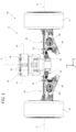
figure 2 is a top view, on a much larger scale, of the axle offigure 1 ; -
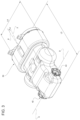
figure 3 is a perspective view, in a further larger scale, of some components of the axle offigures 1 and2 ; and -
figure 4 is an exploded perspective view of the components of the axle offigure 3 . - With reference to
Figure 1 , number 1 indicates a motor vehicle comprising a body 2 defining apassenger compartment 3. - The motor vehicle 1 is a top-of-the-range motor vehicle designed both for a conventional urban/suburban use and for a racing track use.
- Furthermore, the motor vehicle 1 is a hybrid or electric vehicle and is provided with electric batteries (not shown).
- Hereinafter, expressions such as "above", "under", "in front of", "behind" and others similar to them are used with reference to normal driving conditions of the motor vehicle 1.
- Furthermore, it is possible to define:
- a longitudinal axis X integral to the body 2, which, in use, is horizontal and parallel to a normal driving direction of the motor vehicle 1 indicated in
Figures 1 to 4 ; - a transverse axis X integral to the body 2, which, in use, is horizontal and orthogonal to the axis X; and
- an axis Z integral to the body 2, which, in use, is vertical and orthogonal to the axes X, Y.
- The axes X, Y define a horizontal plane P integral to the body 2 and arranged, in use, substantially horizontal.
- The axes X, Z define a vertical plane Q integral to the body 2 and arranged, in use, substantially vertical.
- For the purposes of the following disclosure, the plane Q is a longitudinal middle plane of the motor vehicle 1.
- The body 2 defines a front 6 and a rear 7, with reference to a normal forward driving direction parallel to the axis X.
- The motor vehicle 1 further comprises:
- a
rear axle 10; and - a
front axle 15. - The
axle 10 comprises, in turn: - a pair of
front wheels - a pair of
axle shafts front wheels - The
axle 15 comprises, in turn: - a pair of
rear wheels - a pair of
axle shafts rear wheels - Hence, the motor vehicle 1 comprises:
- an unsprung mass 45 (
figure 2 ) comprising, in turn, the body 2; - a sprung
mass 46 comprising, in turn, theaxles - a pair of front suspensions (not shown) of the known kind and configured to elastically suspend the
front wheels unsprung mass 45 to the body 2 of the sprungmass 46; and - a pair of
rear suspensions rear wheels unsprung mass 45 to the body 2 of the sprungmass 46. - Each front and
rear suspension elastic element 28 and a dampingelement 29 interposed between the respectivefront wheels 11, 12 (rear wheels 16, 17) and the body 2. - Each front suspension and
rear suspension front wheels 11, 12 (rear wheels 16, 17) to move, in a known manner, relative to the body 2, following the irregularities of the ground according to an approximately vertical trajectory, hence parallel to the axis Z. - Consequently, the axes A, B (C, D) of the
front wheels 11, 12 (rear wheels 16, 17) always remain approximately parallel to the axis Y of the body 2. - The
axle 15 further comprises: - an
electric motor 30 comprising anoutput shaft 31 operatively connected to therear wheel 16; and - an
electric motor 35 comprising anoutput shaft 36 operatively connected to therear wheel 17. - The motor vehicle 1 further comprises:
- an
assembly 37 consisting of theelectric motor 30 and of atransmission assembly 40 interposed between theoutput shaft 31 and theaxle shaft 22; and - an
assembly 38 consisting of theelectric motor 31 and of atransmission assembly 41 interposed between the output shaft 32 and theaxle shaft 23. - In particular, the
transmission assemblies offs respective output shafts respective axle shafts - The
output shafts 31, 32 can advantageously rotate around respective axes X1, X2, which are orthogonal relative to the axes C, D. - More in detail, the axes X1, X2 are parallel to one another and to a common axis K.
- The axis K lies on the plane Q of the motor vehicle 1.
- The axis K defines, with the axis X, an angle α (
Figure 3 ) oriented towards the front 6 and ranging from 0 to 90 degrees, more preferably between three and seven degrees. - The angle α is, in the specific case shown herein, five degrees.
- In particular, each
assembly - The motor vehicle 1 further comprises a
casing 50 accommodating bothmotors relative transmission assemblies 40. - In particular, the
casing 50 serves as stator for theelectric motors - The
casing 50 has a length L3 parallel to the axes X1, X2 and a width L4 parallel to the axes X1, X2. The length L3 is greater than the length L4 (Figure 4 ). - Each
casing 50 consists of a pair of half-shells Figure 4 . - The
motors - The
motors rear wheels - The motor vehicle 1 further comprises a braking system (not shown) configured to exert a plurality of braking torques upon the respective
front wheels rear wheels - The aforesaid braking system could be of the traditional kind, namely acting through "friction", or of the regenerative kind capable of transforming the kinetic energy of the braked
front wheels rear wheels - In use, the
electric motors rear wheels corresponding transmission assemblies - The disclosure above reveals evident advantages that can be reached with the invention.
- In particular, the
output shafts 31, 32 of theelectric motors 35 of theaxle 15 can rotate around respective axes X1, X2 orthogonal to the axes C, D of the correspondingrear wheels - In this way, the
electric motors - This reduces the overall dimensions of the motor vehicle 1 parallel to the axis Y in the region of the
axle 15, namely at the rear 7 of the body 2. - This reduction of dimensions allows the body 2 - in particular the rear 7 - to be shaped according to a more aerodynamic layout compared to known solutions discussed in the introduction to the description.
- By so doing, the overall resistance coefficient of the motor vehicle 1 can be reduced, though without affecting the downforce coefficient of the motor vehicle 1.
- Therefore, consumptions are reduced and, hence, the range of the motor vehicle 1 increases, preserving at the same time the ability of the motor vehicle 1 to travel along curved trajectories at high speeds.
- In short, the motor vehicle 1 ensures particularly high performances and can be used for races.
- The
assemblies - Besides the advantages indicated above, this further reduces the overall inertia of the motor vehicle 1, with a consequent improvement in the dynamic performances of the motor vehicle 1.
- Finally, the
axle 15 and the motor vehicle 1 according to the invention can be subjected to changes and variations, which, though, do not go beyond the scope of protection set forth in the appended claims. - In particular, the motor vehicle 1 could comprise one single
electric motor rear wheels front wheels - The
electric motors front axle 10, instead of being part of therear axle 15, thus obtaining a front-wheel drive motor vehicle 1. - The
front axle 10 could comprise electric motors similar to theelectric motors axle 15, thus obtaining an all-wheel drive motor vehicle 1.
Claims (14)
- An electric axle (15; 10) for a motor vehicle (1), comprising:- a first wheel (16; 11), which can rotate around a first axis (C; A);- a second wheel (17; 12), which can rotate around a second axis (D; B); and- at least one first electric motor (30, 35), which is operatively connected to said first and second wheel (16, 17; 11, 12);said first electric motor (30, 35) comprising, in turn, a first output shaft (31, 36), which can rotate around a third axis (X1, X2) orthogonal to said first and second axis (C, D; A, B);said first electric motor (30, 35) being operatively connected to said first wheel (16, 11) and comprising a second electric motor (35, 30) operatively connected to said second wheel (17, 12);said second electric motor (35, 30) comprising, in turn, a second output shaft (36, 31), which can rotate around a fourth axis (X2, X1) orthogonal to said first and second axis (C, D; A, B) and parallel to said third axis (X1, X2);characterized in that said first transmission assembly (40) is interposed between said first output shaft (31) and said first wheel (16, 17; 10, 11);said axle (15) further comprising:- a second transmission assembly (41) interposed between said second output shaft (36) and said second wheel (17; 12); and- a casing (50) accommodating said first electric motor, said second electric motor (30, 35), said first transmission assembly and said second transmission assembly (40, 41);said casing (50) having a second length (L3) parallel to said third axis (X1, X2) and a second width (L4) orthogonal to said third axis (X1, X2); said second length being greater than said second width;said casing (50) consisting of a pair of half-shells (51, 52).
- The electric axle according to claim 1, characterized in that it comprises at least one first transmission assembly (40, 41) interposed between said first electric motor (30, 35) and said first and second wheel (16, 17; 10, 11).
- The electric axle according to claim 1 or 2, characterized in that said first electric motor (30, 35) and said first transmission assembly (40, 41) have a first length (L1) parallel to said third axis (X1, X2) and a first width (L2) orthogonal to said third axis (X1, X2); said first length (L1) being greater than said first width (L2) .
- The axle according to any one of the preceding claims, characterized in that said first and second electric motor (30, 35) can be operated independently of one another.
- A motor vehicle (1) comprising:- a body (2) defining a front (6) and a rear (7), with reference to a normal forward driving direction of the motor vehicle (1);- a fourth longitudinal axis (X), which is parallel to said normal forward moving direction of the motor vehicle (1) and is horizontal in a normal driving condition of the motor vehicle (1); and- an axle (10, 15) according to any one of the preceding claims;said front and rear (6, 7) being arranged one after the other in a direction parallel to said fourth axis (X);characterized in that said first electric motor (30, 35) extends from the side of said front (6) relative to said first and second axis (C, D; A, B), moving along said fourth axis (X).
- The motor vehicle according to claim 5, characterized in that said third axis (X1, X2) is inclined relative to said fourth axis (X), preferably at an angle (α) ranging from 3 to 7 degrees.
- A motor vehicle (1) comprising:- a body (2) defining a front (6) and a rear (7), with reference to a normal forward driving direction of the motor vehicle (1);an electric axle (10, 15);said electric axle (15; 10) comprising, in turn:- a first wheel (16; 11), which can rotate around a first axis (C; A);- a second wheel (17; 12), which can rotate around a second axis (D; B); and- at least one first electric motor (30, 35), which is operatively connected to said first and second wheel (16, 17; 11, 12);
said first electric motor (30, 35) comprising, in turn, a first output shaft (31, 36), which can rotate around a third axis (X1, X2) orthogonal to said first and second axis (C, D; A, B); and- a fourth longitudinal axis (X), which is parallel to said normal forward moving direction of the motor vehicle (1) and is horizontal in a normal driving condition of the motor vehicle (1);said front and rear (6, 7) being arranged one after the other in a direction parallel to said fourth axis (X);said first electric motor (30, 35) extending from the side of said front (6) relative to said first and second axis (C, D; A, B), moving along said fourth axis (X);characterized in that said third axis (X1, X2) is inclined relative to said fourth axis (X), preferably at an angle (α) ranging from 3 to 7 degrees. - The motor vehicle according to claim 7, characterized in that it comprises at least one first transmission assembly (40, 41) interposed between said first electric motor (30, 35) and said first and second wheel (16, 17; 10, 11).
- The motor vehicle according to claim 7 or 8, characterized in that said first electric motor (30, 35) and said first transmission assembly (40, 41) have a first length (L1) parallel to said third axis (X1, X2) and a first width (L2) orthogonal to said third axis (X1, X2); said first length (L1) being greater than said first width (L2) .
- The motor vehicle according to any one of the claims from 7 to 9, characterized in that said first electric motor (30, 35) is operatively connected to said first wheel (16, 11), and in that it comprises a second electric motor (35, 30) operatively connected to said second wheel (17, 12);
said second electric motor (35, 30) comprising, in turn, a second output shaft (36, 31), which can rotate around a fourth axis (X2, X1) orthogonal to said first and second axis (C, D; A, B) and parallel to said third axis (X1, X2) . - The motor vehicle according to claim 10, characterized in that said first transmission assembly (40) is interposed between said first output shaft (31) and said first wheel (16, 17; 10, 11);said axle (15) further comprising:- a second transmission assembly (41) interposed between said second output shaft (36) and said second wheel (17; 12); and- a casing (50) accommodating said first electric motor, said second electric motor (30, 35), said first transmission assembly and said second transmission assembly (40, 41);said casing (50) having a second length (L3) parallel to said third axis (X1, X2) and a second width (L4) orthogonal to said third axis (X1, X2); said second length being greater than said second width.
- The motor vehicle according to claim 10 or 11, characterized in that said first and second electric motor (30, 35) can be operated independently of one another.
- The motor vehicle according to claim 5 or 6 or according to any one of the claims from 7 to 12, characterized in that it comprises, with reference to said normal forward driving direction:- a front axle (10); and- said rear axle (15).
- The motor vehicle according to claim 5 or 6 or according to any one of the claims from 7 to 13, characterized in that it is a hybrid or electric vehicle.
Priority Applications (1)
| Application Number | Priority Date | Filing Date | Title |
|---|---|---|---|
| EP25216398.5A EP4699837A3 (en) | 2023-04-13 | 2024-04-09 | Axle and motor vehicle comprising said axle |
Applications Claiming Priority (1)
| Application Number | Priority Date | Filing Date | Title |
|---|---|---|---|
| IT102023000007071A IT202300007071A1 (en) | 2023-04-13 | 2023-04-13 | AXLE AND MOTOR VEHICLE INCLUDING SUCH AXLE |
Related Child Applications (1)
| Application Number | Title | Priority Date | Filing Date |
|---|---|---|---|
| EP25216398.5A Division EP4699837A3 (en) | 2023-04-13 | 2024-04-09 | Axle and motor vehicle comprising said axle |
Publications (1)
| Publication Number | Publication Date |
|---|---|
| EP4446147A1 true EP4446147A1 (en) | 2024-10-16 |
Family
ID=86942794
Family Applications (2)
| Application Number | Title | Priority Date | Filing Date |
|---|---|---|---|
| EP24169200.3A Pending EP4446147A1 (en) | 2023-04-13 | 2024-04-09 | Axle and motor vehicle comprising said axle |
| EP25216398.5A Pending EP4699837A3 (en) | 2023-04-13 | 2024-04-09 | Axle and motor vehicle comprising said axle |
Family Applications After (1)
| Application Number | Title | Priority Date | Filing Date |
|---|---|---|---|
| EP25216398.5A Pending EP4699837A3 (en) | 2023-04-13 | 2024-04-09 | Axle and motor vehicle comprising said axle |
Country Status (3)
| Country | Link |
|---|---|
| US (1) | US20240343101A1 (en) |
| EP (2) | EP4446147A1 (en) |
| IT (1) | IT202300007071A1 (en) |
Citations (6)
| Publication number | Priority date | Publication date | Assignee | Title |
|---|---|---|---|---|
| US20010011611A1 (en) * | 1996-01-24 | 2001-08-09 | Klaus-Peter Poerschmann | Chasis for commercial vehicles |
| US20110259657A1 (en) | 2010-04-23 | 2011-10-27 | Dr. Ing. H.C.F. Porsche Aktiengesellschaft | Vehicle having electric drive |
| US20170050514A1 (en) * | 2014-04-29 | 2017-02-23 | Zhejiang Geely Holding Group Co., Ltd | Integrated steering drive axle for vehicle and electric vehicle |
| EP3597464A1 (en) | 2018-07-17 | 2020-01-22 | FERRARI S.p.A. | Motor vehicle comprising an electric axle |
| CN110758076A (en) * | 2019-11-11 | 2020-02-07 | 北京理工大学 | A four-wheel independent drive system for a new energy vehicle |
| US11364797B1 (en) * | 2021-06-09 | 2022-06-21 | Arvinmeritor Technology, Llc | Multi-speed axle assembly having a one-way freewheel clutch |
Family Cites Families (6)
| Publication number | Priority date | Publication date | Assignee | Title |
|---|---|---|---|---|
| US5465806A (en) * | 1989-03-31 | 1995-11-14 | Kabushiki Kaisha Shikoku Sogo Kenkyujo | Electric vehicle |
| US6276474B1 (en) * | 1997-02-18 | 2001-08-21 | Rockwell Heavy Vehicle Systems, Inc. | Low floor drive unit assembly for an electrically driven vehicle |
| IT1319879B1 (en) * | 2000-02-02 | 2003-11-12 | Graziano Trasmissioni Spa | AXLE TRANSMISSION UNIT FOR ELECTRIC DRIVE VEHICLES. |
| EP2026988A2 (en) * | 2006-04-03 | 2009-02-25 | BluWav Systems, LLC | Vehicle power unit designed as retrofittable axle comprising motor, battery and suspension |
| WO2019014479A1 (en) * | 2017-07-12 | 2019-01-17 | Axle Tech International Ip Holdings, Llc. | Axle assembly for low floor vehicle |
| IT202100021065A1 (en) * | 2021-08-04 | 2023-02-04 | Ferrari Spa | METHOD FOR DETERMINING AN OPTIMIZED TORQUE DISTRIBUTION AT THE DRIVE WHEELS OF A ROAD VEHICLE AND RELATED ROAD VEHICLE |
-
2023
- 2023-04-13 IT IT102023000007071A patent/IT202300007071A1/en unknown
-
2024
- 2024-04-08 US US18/629,473 patent/US20240343101A1/en active Pending
- 2024-04-09 EP EP24169200.3A patent/EP4446147A1/en active Pending
- 2024-04-09 EP EP25216398.5A patent/EP4699837A3/en active Pending
Patent Citations (6)
| Publication number | Priority date | Publication date | Assignee | Title |
|---|---|---|---|---|
| US20010011611A1 (en) * | 1996-01-24 | 2001-08-09 | Klaus-Peter Poerschmann | Chasis for commercial vehicles |
| US20110259657A1 (en) | 2010-04-23 | 2011-10-27 | Dr. Ing. H.C.F. Porsche Aktiengesellschaft | Vehicle having electric drive |
| US20170050514A1 (en) * | 2014-04-29 | 2017-02-23 | Zhejiang Geely Holding Group Co., Ltd | Integrated steering drive axle for vehicle and electric vehicle |
| EP3597464A1 (en) | 2018-07-17 | 2020-01-22 | FERRARI S.p.A. | Motor vehicle comprising an electric axle |
| CN110758076A (en) * | 2019-11-11 | 2020-02-07 | 北京理工大学 | A four-wheel independent drive system for a new energy vehicle |
| US11364797B1 (en) * | 2021-06-09 | 2022-06-21 | Arvinmeritor Technology, Llc | Multi-speed axle assembly having a one-way freewheel clutch |
Also Published As
| Publication number | Publication date |
|---|---|
| US20240343101A1 (en) | 2024-10-17 |
| EP4699837A3 (en) | 2026-04-29 |
| IT202300007071A1 (en) | 2024-10-13 |
| EP4699837A2 (en) | 2026-02-25 |
Similar Documents
| Publication | Publication Date | Title |
|---|---|---|
| US11679662B2 (en) | Suspension rear axle comprising two electric motors | |
| EP1547853B1 (en) | Driver of electric automobile | |
| WO2004073155A1 (en) | In-wheel electric motor system | |
| KR20190008873A (en) | Motor gear box assembly | |
| CN1074869A (en) | The driving device of automobile | |
| CN110509915B (en) | Four-wheel drive automobile lateral stability control method based on time-varying speed | |
| CN110949498B (en) | An electric vehicle and a wheel hub structure with integrated steering and suspension | |
| EP4105050B1 (en) | Drive axle system | |
| US6808033B2 (en) | Vehicle suspension system | |
| EP4446147A1 (en) | Axle and motor vehicle comprising said axle | |
| JP3008250B2 (en) | Torque distribution control device for left and right non-main driving wheels of vehicle | |
| EP4446149B1 (en) | Motor vehicle | |
| Parczewski et al. | Comparison of overcoming inequalities of the road by a vehicle with a conventional drive system and electric motors placed in the wheels | |
| CN104129287B (en) | Differential device of rear axle of vehicle | |
| CN112805168A (en) | shaft drive | |
| CN212672209U (en) | Universal joint steel wire flexible shaft for connecting wheel driving generator | |
| CN200939823Y (en) | Front driving electric 4-wheel cycle having front-mounted dynamo | |
| Spentzas et al. | Generalisation of the concept of electronic differential | |
| JP6425937B2 (en) | Vehicle roll control device | |
| US20250282427A1 (en) | Wheel for a motor vehicle and method for manufacturing a fairing for said wheel | |
| US20240343230A1 (en) | Motor vehicle | |
| CN204020557U (en) | Vehicle rear axle differential gear | |
| RU2797069C1 (en) | Method for controlling an individual traction electric drive of driving wheels of a multi-wheeled vehicle | |
| Kopczyński | Active torque distribution strategy for electric vehicle independent axle drive | |
| Myskiv | Analysis of the drive of electric vehicles with its different configurations |
Legal Events
| Date | Code | Title | Description |
|---|---|---|---|
| PUAI | Public reference made under article 153(3) epc to a published international application that has entered the european phase |
Free format text: ORIGINAL CODE: 0009012 |
|
| STAA | Information on the status of an ep patent application or granted ep patent |
Free format text: STATUS: THE APPLICATION HAS BEEN PUBLISHED |
|
| AK | Designated contracting states |
Kind code of ref document: A1 Designated state(s): AL AT BE BG CH CY CZ DE DK EE ES FI FR GB GR HR HU IE IS IT LI LT LU LV MC ME MK MT NL NO PL PT RO RS SE SI SK SM TR |
|
| STAA | Information on the status of an ep patent application or granted ep patent |
Free format text: STATUS: REQUEST FOR EXAMINATION WAS MADE |
|
| 17P | Request for examination filed |
Effective date: 20250415 |
|
| STAA | Information on the status of an ep patent application or granted ep patent |
Free format text: STATUS: EXAMINATION IS IN PROGRESS |
|
| 17Q | First examination report despatched |
Effective date: 20250805 |
|
| GRAP | Despatch of communication of intention to grant a patent |
Free format text: ORIGINAL CODE: EPIDOSNIGR1 |
|
| STAA | Information on the status of an ep patent application or granted ep patent |
Free format text: STATUS: GRANT OF PATENT IS INTENDED |
|
| INTG | Intention to grant announced |
Effective date: 20260205 |