EP4446016A1 - A fixture for use in coating operation - Google Patents
A fixture for use in coating operation Download PDFInfo
- Publication number
- EP4446016A1 EP4446016A1 EP23167834.3A EP23167834A EP4446016A1 EP 4446016 A1 EP4446016 A1 EP 4446016A1 EP 23167834 A EP23167834 A EP 23167834A EP 4446016 A1 EP4446016 A1 EP 4446016A1
- Authority
- EP
- European Patent Office
- Prior art keywords
- holder
- fixture
- holders
- edge
- elements
- Prior art date
- Legal status (The legal status is an assumption and is not a legal conclusion. Google has not performed a legal analysis and makes no representation as to the accuracy of the status listed.)
- Pending
Links
Images


Classifications
-
- B—PERFORMING OPERATIONS; TRANSPORTING
- B05—SPRAYING OR ATOMISING IN GENERAL; APPLYING FLUENT MATERIALS TO SURFACES, IN GENERAL
- B05B—SPRAYING APPARATUS; ATOMISING APPARATUS; NOZZLES
- B05B13/00—Machines or plants for applying liquids or other fluent materials to surfaces of objects or other work by spraying, not covered by groups B05B1/00 - B05B11/00
- B05B13/02—Means for supporting work; Arrangement or mounting of spray heads; Adaptation or arrangement of means for feeding work
- B05B13/0292—Means for supporting work; Arrangement or mounting of spray heads; Adaptation or arrangement of means for feeding work devices for holding several workpieces to be sprayed in a spaced relationship, e.g. vehicle doors spacers
-
- B—PERFORMING OPERATIONS; TRANSPORTING
- B05—SPRAYING OR ATOMISING IN GENERAL; APPLYING FLUENT MATERIALS TO SURFACES, IN GENERAL
- B05B—SPRAYING APPARATUS; ATOMISING APPARATUS; NOZZLES
- B05B12/00—Arrangements for controlling delivery; Arrangements for controlling the spray area
- B05B12/16—Arrangements for controlling delivery; Arrangements for controlling the spray area for controlling the spray area
- B05B12/20—Masking elements, i.e. elements defining uncoated areas on an object to be coated
-
- B—PERFORMING OPERATIONS; TRANSPORTING
- B05—SPRAYING OR ATOMISING IN GENERAL; APPLYING FLUENT MATERIALS TO SURFACES, IN GENERAL
- B05B—SPRAYING APPARATUS; ATOMISING APPARATUS; NOZZLES
- B05B13/00—Machines or plants for applying liquids or other fluent materials to surfaces of objects or other work by spraying, not covered by groups B05B1/00 - B05B11/00
- B05B13/02—Means for supporting work; Arrangement or mounting of spray heads; Adaptation or arrangement of means for feeding work
- B05B13/0207—Means for supporting work; Arrangement or mounting of spray heads; Adaptation or arrangement of means for feeding work the work being an elongated body, e.g. wire or pipe
- B05B13/0214—Means for supporting work; Arrangement or mounting of spray heads; Adaptation or arrangement of means for feeding work the work being an elongated body, e.g. wire or pipe the liquid or other fluent material being applied to the whole periphery of the cross section of the elongated body
Definitions
- the element comprises a capacitor
- the capacitor comprises turns of a polymer film, preferably a polypropylene film, and that, preferably, the element/capacitor has a cylindrical shape.
- each first holder has the same maximum width as the second holder to which it is associated and the maximum width of each first holder and the second holder to which it is associated is located at the interface between the two holding portions.
- the fixture comprises a sealing element extending around an inner periphery of each holding portion.
- the first and second member are constituted by a first material
- said fixture comprises a masking member applied onto and covering the front surface of the respective first and second member, the masking member has openings of corresponding shape, size and position as the holding portions formed by said first and second holders, the masking member is constituted by a second material having higher abrasion resistance than the first material.
- the masking member comprises a first part having profile corresponding to the first holders of the first member and attached to the front surface of the first member, and a second part having profile corresponding to the second holders of the second member and attached to the front surface of the second member.
- the first part covers, and protects, the front surface of the first member
- the second part covers, and protects, the front surface of the second member.
- the first member comprises a first part and a second sheet, connected to each other and arranged at a distance from each other, in parallel with each other and having a corresponding shape and having first holders of corresponding shape, size and position, said first edge of the first member being formed by a first edge of the first part and a corresponding first edge of the second part of the first member, and each holder being provided with a sealing element on its inner periphery.
- the second member comprises a first part and a second sheet, arranged at a distance from each other, in parallel with each other and having a corresponding shape and having second holders of corresponding shape, size and position, said second edge of the second member being formed by a second edge of the first part and a corresponding second edge of the second part of the second member, and each holder being provided, and each holder being provided with a sealing element on its inner periphery.
- each first holder has a cross section that defines a semi-circle
- each second holder has a cross-section that defines a half circle
- the elements aimed to be coated and to be held in the fixture have a circular cross section with a diameter corresponding to the diameter of the holes defined by each pair of first holders and second holders.
- the fixture comprises a holder element on which the first member and second member are stacked, the second member is arranged on top of the first member.
- the first holder is a holder in the first member and the second holder is a holder in the second member.
- the arrangement further comprises a device for cleaning the rails, the device is configured to grip the second member and move it to a cleaning position in the cleaning device, to pick and remove coated elements positioned in the first holders of the first member, and thereafter move the first member to a cleaning position in the cleaning device.
- a method of coating elements comprising the steps of positioning a first member of a fixture according to embodiments of the present invention with its first edge pointing upwards, positioning elements to be coated in said holders, one in each first holder, positioning the second member on top of the first member, with the second edge turned towards the first edge, and with each second holder opposed to a respective first holder, such that the elements are sealingly held in holes defined by the pairs of opposed first and second holders, and coating, by means of a coating device, an end of the elements that is exposed by said holes.
- the method of coating as discussed provides efficient and automated coating of end surfaces of elements while preventing coating material from being applied on side surfaces of said elements during the coating operation.
- the method further comprises the steps of removing the second member from the first member, and removing each element from the first holder in which is positioned.
- the method further comprising the step of cleaning front surfaces of the rails or mask sheets that have been subjected to coating during the coating of said elements.
- the present invention pertains to a fixture for holding an element during coating operation.
- the production line carries a certain level of automation.
- the efficiency of the system is also paramount as a single issue can affect multiple components in a batch of various batches.
- mass production of capacitors it is needed to coat the two ends of the capacitors with at least a layer metal.
- a fixture is generally use that allow holding the coating element in correct position in order to perform coating with high efficiency.
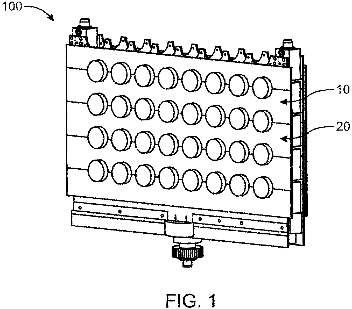
- FIG. 1 shows an assembled view of the fixture 100 of the present invention, in said fixture a plurality of the first member 10 and second member 20 are assembled in a stacked manner.
- the first member 10 of the fixture 100 has a front surface and a plurality of first holders 12.
- the plurality of first holders 12 are arranged along a first edge 14 of the first member 10.
- the second member 20 has a front surface and a plurality of second holders 22 that are arranged along a second edge 24 of the second member 20.
- the first member 10 or the second member 20 includes plurality of first holders 12 or second holder 22 respectively.
- a single first member 10 (or second member 20) is shown, however, for the ease of understanding said member would be explained considering the upper portion of said member as the first member 10 and lower part as the second member 20.
- the said arrangement is considered for the purpose of explaining the features of the fixture 100, further, as the first member 10 and second member are assembled in stacked manner on top of each other (as seen in FIG. 1 ) said assumption will be useful for briefing the invention.
- the first member 10 and the second member 20 are arranged such that the first edge 14 and the second edge 24 are attachable to each other such that the plurality of first holder 12 and plurality of second holders 22 are aligned with each other.
- attachments means 30 are provided in the fixture 100.
- Attachment means 30 according to the embodiment of the present invention can be seen in FIG. 3 and 4 .
- the attachment means 30 of the fixture 100 allows a removable attachment of the first edge 14 of the first member 10 to the second edge 24 of the second member 20.
- the removable attachment is made in a position in which the front surfaces of the first member 10 and the second member 20 are in alignment with each other such that the respective first holder 12 is opposite to a respective associated second holder 22 so as to form a holding portion 40 configured to hold the element 200 (as seen in FIG. 6 and 7 ).
- the attachment means 30 as shown in FIG.
- the attachment means can include a lever that can be attached the corresponding member and may be bolted or screwed.
- the alignment member 30 are configured to align the respective first member 10 and the second member 20 so that the first holder 12 and the corresponding second holder 22 are aligned with each other to form the holding portion 40.
- the first holder 12 may be formed as a holder in the first member 10 and the second holder 22 is a holder formed in the second member 20. Further, the profile of the each first holder 12 has a cross section that defines a semi-circle, further, each second holder 22 has a cross-section that defines a semi-circle.
- the said profile of the respective first holder 10 and second holder 20 when aligned together may form a circular profile. This may be specifically done to the elements 200 aimed to be coated and to be held in the fixture 100 may have a circular cross section with a diameter corresponding to the diameter of the holes defined by each pair of first holder 12 and second holders 22.
- each first holder 12 has the same maximum width as the second holder 22 to which it is associated. Further, the maximum width of each first holder 12 and the second holder 22 to which it is associated is located at the interface between the two holding portions 40. In alternate embodiments the different profiles may be formed to accommodate elements of different shapes and sizes.
- the fixture may further comprise a holder element 30' on which the first members 10 and second members 20 can be stacked.
- the stacking arrangement using the holder element 30' can be seen in FIG. 3 .
- the second member 20 is arranged on top of the first member 10.
- the holder member comprises a lever and holder mechanism on which the first member 10 and the second member 20 are attached may be using a bolting arrangement or a screwing arrangement.
- Other methods of attaching the first member 10 and the second member 20 to the holder element 30' can also be used such a clipping, or a snap fit mechanism.
- the fixture 100 may further comprise a sealing element 50 that extends around an inner periphery of each holding portion 40.
- the sealing element 50 may be provided prevent the ingress of the coating material inside the fixture and subsequently prevent the contamination of other surfaces of the element 200 that needs to be coated.
- the first member 10 and second member 20 may be constituted by a first material. Said material may be metallic or may be any material that can be configured to hold the element in position.
- the fixture 100 further comprises a masking member 60 applied onto and covering the front surface of the respective first member 10 and second member 20.
- the masking member 60 may be provided to enable easy cleaning of the fixture 100.
- the masking member 60 may be attached in a removable manner. As shown in FIG. 5 , the masking member 60 may be snap fitted on to the first member 10 and the second member 20.
- the masking member 60 has openings of corresponding shape, size and position as the holding portions 40 that is formed by said first holders 12 and second holders 22.
- the masking member 60 is constituted by a second material having higher abrasion resistance than the first material. The material of the masking member 60 may choose to prevent the coating material from sticking on to the masking member 60 during coating operation.
- the second member 20 may comprise a first part 26 and a second part 28, arranged at a distance from each other, and in parallel with each other.
- the first part 26 and a second part 28, may have a corresponding shape, size and position.
- said second edge 24 of the second member 20 may be formed by a second edge 24 of the first part 26 and a corresponding second edge 24 of the second part 28 of the second member 20.
- Each holder 22 may be provided, with a sealing element 50 on its inner periphery.
- FIG. 8A to FIG. 9C shows various sealing elements 50 according to the embodiments of the present invention. Specifically FIG. 9A shows the sealing of the holding portion 40 using said sealing elements 50.
- the element 200 to be coated may be a capacitors such as film capacitors that are made of turns of polypropylene film wrapped around a mandrel giving a cylindrical shape to the capacitor.
- the electrodes may need to be metalized in a process known as Schoopage process, where the projecting ends of the electrodes are covered with a liquefied contact metal (such as tin, zinc or aluminium), which may be sprayed with compressed air on both lateral ends of the winding.
- a liquefied contact metal such as tin, zinc or aluminium
- the shape and size of the first holder 12, second holder 22 and subsequently the holding portion 40 may be designed according to the capacitor profile. Further, it may be understood that the different components having different shapes and size that need to be coated and have a similar coating requirements can also be coated using the fixture 100 of the present invention without deviating from the scope of the invention.
- an arrangement for coating of elements 200 in particular cylindrical capacitor elements is envisioned.
- the arrangement comprises a fixture 100 according to the embodiments of the present invention as discussed earlier. Further the arrangement may comprise a device configured to grip a first member 10 and place the first member 10 in a first position with its first edge 14 directed upwards. The device may further pick elements that needs to be coated and place them in a respective first holder 12 of the first member 10 (as shown in FIG. 6 ). The device may then grip the second member 20 and place the second member 20 on top of the first members 10 such that the first holder 12 and second holders 22 form said holding portions 40, in which said elements 200 are positioned.
- the arrangement may be done such that an end of each element 200 is exposed by the holding portions 40 formed by the first holders 12 and second holders 22 in the front surface of the first member 10 and second members 20.
- the arrangement may further comprise a coating device configured to apply a metallic coat onto said ends of said elements from a position opposite to said front surfaces.
- the device may be guided using the attachment means 30 and the holding element 30' as discussed earlier.
- the arrangement according to the embodiment of the invention further comprises a device for cleaning the rails, in particular for cleaning the front surfaces of the masking members that have been subjected to coating during the coating operation.
- the device may be configured to grip the second member 20 and move it to a cleaning position in the cleaning device, to pick and remove coated elements positioned in the first holder 12 of the first member 10, and thereafter move the first member 10 to a cleaning position in the cleaning device.
- the element can be coated with a metallic coat.
- the coating method may comprise the steps of positioning a first member 10 of a fixture 100 according to the embodiments of the present invention with its first edge 14 pointing upwards. Afterwards, positioning elements 200 to be coated in said holders, one in each first holder. The profile of the element and the holders may be same so as to enable easy positioning and efficiency. Further, the method includes positioning the second member 20 on top of the first member, with the second edge 24 turned towards the first edge, and with each second holder 22 opposed to a respective first holder, such that the elements are sealingly held in holes defined by the pairs of opposed first and second holders. The method then includes the step of coating, by means of a coating device, an end of the elements that is exposed by said holes. The purpose of the said method and previously discussed arrangement is to coat the end surface of the coating element preventing any contamination of the other surfaces.
- the method further comprises for the purpose of cleaning the fixture the steps of removing the second member 20 from the first member, and removing each element 200 from the first holder 12 in which is positioned.
- the then includes the step of cleaning front surfaces of the rails or mask sheets that have been subjected to coating during the coating of said elements.
Landscapes
- Details Or Accessories Of Spraying Plant Or Apparatus (AREA)
Abstract
The present invention pertains to a fixture (100) for holding elements (200) during coating operation. The fixture comprises a first member (10), having a front surface and a plurality of first holders (12), a second member (20), having a front surface and a plurality of second holders (22), and an attachment means (30) for removable attachment of the first edge (14) of the first member (10) to the second edge (24) of the second member (20) in a position in which the front surfaces of the first member (10) and the second member (20) are in alignment with each other. The respective first holder (12) is arranged opposite to a respective associated second holder (22) so as to form a holding portion (40) configured to hold the element (200).
Description
- The invention relates to a fixture for use in coating operation, more particularly the invention relates to a fixture for holding an element during coating operations.
- Film capacitors, plastic film capacitors, film dielectric capacitors, or polymer film capacitors, generically called as film caps as well as power film capacitors, are electrical capacitors with an insulating plastic film as the dielectric, sometimes combined with paper as carrier of the electrodes. These films may be made extremely thin using a sophisticated film drawing process. Once the film is manufactured, it may be metallized or left untreated, depending on the needed properties of the capacitor. In the manufacturing process of thin-film dielectric capacitors, metal coating may be a very critical production process. This process is to use compressed air to coat a liquid metal from a nozzle on the end face of the capacitor core at a high speed to form a metal electrode surface.
- In existing coating process, the coating gun may be fixedly arranged, and the capacitors may be placed on a conveyor and the coating may be performed sequentially. Once the coating is completed, the conveyor is mostly turned over to coat the other side of the capacitor. In large scale manufacturing systems where large scale coating needs to be performed it is difficult to flip the capacitor individually, in addition this may affect the efficiency of coating as well. Further, during coating it is important to coat only the end portions of the capacitor and the remaining portions shouldn't be coated so as not to effect the workability of the capacitor.
- The present methods and device used for coating capacitors include one or more of the issues as stated above. Therefore there is a need for a device or method for coating capacitors that can overcome one or more of the above listed drawbacks of current coating processes.
- It is an object of the invention to present a fixture, an arrangement and a method that promotes efficient and automated coating of end surfaces of elements while preventing coating material from being applied on side surfaces of said elements during the coating operation.
- It is also an object of the invention to present a fixture and arrangement that promotes efficient and automated cleaning of surfaces thereof that has been subjected to coating material during a coating operation in which end surfaces of elements positioned in the fixture of the arrangement has been coated.
- In an embodiment of the present invention, envisioned is, a fixture for holding elements during coating operation thereof, the fixture comprising a first member, having a front surface and a plurality of first holders, arranged along an first edge of the first member; a second member, having a front surface and a plurality of second holders, arranged along a second edge of the second member; and attachment means for removable attachment of the first edge of the first member to the second edge of the second member in a position in which the front surfaces of the first member and the second member are in alignment with each other, and in which each respective first holder is opposite to a respective associated second holder so as to form an holding portion configured to hold the element. The technical effect of the said fixture is that efficient and automated coating of end surfaces of elements can be performed while preventing coating from being applied on side surfaces of said elements during the coating operation. According to one embodiment, the element comprises a capacitor, and that, according to yet an embodiment, the capacitor comprises turns of a polymer film, preferably a polypropylene film, and that, preferably, the element/capacitor has a cylindrical shape.
- In an embodiment of the present invention, each first holder has the same maximum width as the second holder to which it is associated and the maximum width of each first holder and the second holder to which it is associated is located at the interface between the two holding portions.
- In an embodiment of the present invention, the fixture comprises a sealing element extending around an inner periphery of each holding portion.
- In an embodiment of the present invention, the first and second member are constituted by a first material, said fixture comprises a masking member applied onto and covering the front surface of the respective first and second member, the masking member has openings of corresponding shape, size and position as the holding portions formed by said first and second holders, the masking member is constituted by a second material having higher abrasion resistance than the first material.
- In an embodiment of the present invention, the masking member comprises a first part having profile corresponding to the first holders of the first member and attached to the front surface of the first member, and a second part having profile corresponding to the second holders of the second member and attached to the front surface of the second member. The first part covers, and protects, the front surface of the first member, and the second part covers, and protects, the front surface of the second member.
- In an embodiment of the present invention, the first member comprises a first part and a second sheet, connected to each other and arranged at a distance from each other, in parallel with each other and having a corresponding shape and having first holders of corresponding shape, size and position, said first edge of the first member being formed by a first edge of the first part and a corresponding first edge of the second part of the first member, and each holder being provided with a sealing element on its inner periphery.
- In an embodiment of the present invention, the second member comprises a first part and a second sheet, arranged at a distance from each other, in parallel with each other and having a corresponding shape and having second holders of corresponding shape, size and position, said second edge of the second member being formed by a second edge of the first part and a corresponding second edge of the second part of the second member, and each holder being provided, and each holder being provided with a sealing element on its inner periphery.
- In an embodiment of the present invention, each first holder has a cross section that defines a semi-circle, and each second holder has a cross-section that defines a half circle, and the elements aimed to be coated and to be held in the fixture have a circular cross section with a diameter corresponding to the diameter of the holes defined by each pair of first holders and second holders.
- In an embodiment of the present invention, the fixture comprises a holder element on which the first member and second member are stacked, the second member is arranged on top of the first member.
- In an embodiment of the present invention, the first holder is a holder in the first member and the second holder is a holder in the second member.
- In an embodiment of the present invention, envisioned is, an arrangement for coating of elements, in particular cylindrical capacitor elements, said arrangement comprises a fixture according to any of the preceding embodiments of the present invention, a device configured to grip a first member and place the first member in a first position with its first edge directed upwards, picking elements to be coated and placing them in a respective first holder of the first member, grip the second member and place the second member on top of the first members such that the first and second holders form said holding portions, in which said elements are positioned, such that an end of each element is exposed by the holding portions formed by the first and second holders in the front surface of the first and second members, and a coating device configured to apply a metallic coat onto said ends of said elements from a position opposite to said front surfaces. The technical effect of the embodiment is that efficient and automated coating of end surfaces of elements while preventing coating material from being applied on side surfaces of said elements during the coating operation.
- In an embodiment of the present invention, the arrangement further comprises a device for cleaning the rails, the device is configured to grip the second member and move it to a cleaning position in the cleaning device, to pick and remove coated elements positioned in the first holders of the first member, and thereafter move the first member to a cleaning position in the cleaning device.
- In an embodiment of the present invention, envisioned is, a method of coating elements, comprising the steps of positioning a first member of a fixture according to embodiments of the present invention with its first edge pointing upwards, positioning elements to be coated in said holders, one in each first holder, positioning the second member on top of the first member, with the second edge turned towards the first edge, and with each second holder opposed to a respective first holder, such that the elements are sealingly held in holes defined by the pairs of opposed first and second holders, and coating, by means of a coating device, an end of the elements that is exposed by said holes. The method of coating as discussed provides efficient and automated coating of end surfaces of elements while preventing coating material from being applied on side surfaces of said elements during the coating operation.
- In an embodiment of the present invention, the method further comprises the steps of removing the second member from the first member, and removing each element from the first holder in which is positioned.
- In an embodiment of the present invention, the method further comprising the step of cleaning front surfaces of the rails or mask sheets that have been subjected to coating during the coating of said elements.
-
-
FIG. 1 shows an assembled view of a fixture for holding elements during coating operation, according to an embodiments of the present invention. -
FIG. 2 shows a first member or second member of a fixture, according to the embodiments of the present invention. -
FIG. 3 and 4 , shows an attachment means of a fixture, according to the embodiments of the present invention. -
FIG. 5 shows a sealing element and a masking member of the fixture, according to the embodiments of the present invention. -
FIG. 6 shows an arrangement of an element to be coated in a fixture, according to the embodiments of the present invention. -
FIG. 7 shows an assembled view of the first member and second member showing a holding portion, according to the embodiments of the present invention. -
FIG. 8a-8b and9a-9c shows an assembly of sealing element in the fixture, according to the embodiments of the present invention. -
FIG. 10 shows an exploded view of a fixture for holding elements during coating operation, according to an alternate embodiments of the present invention. -
FIG. 10a shows a masking element for a fixture ofFIG. 10 , according to an embodiments of the present invention. -
FIG. 11 shows an assembled view of a fixture forFIG. 10 , according to an alternate embodiments of the present invention. -
FIG. 12 shows a masking element, according to an alternate embodiment of the present invention. - The embodiments herein and the various features and advantageous details thereof are explained more fully with reference to the non-limiting embodiments and detailed in the following description. Descriptions of well-known components and processing techniques are omitted so as to not unnecessarily obscure the embodiments herein. The examples used herein are intended merely to facilitate an understanding of ways in which the embodiments herein may be practiced and to further enable those of skill in the art to practice the embodiments herein. Accordingly, the examples should not be construed as limiting the scope of the embodiments herein.
- Embodiments of the present disclosure will be described and illustrated more fully hereinafter with reference to the accompanying drawings. However, the solutions disclosed herein may be implemented in many different forms and should not be construed as limited to the embodiments set forth herein.
- The present invention pertains to a fixture for holding an element during coating operation. In industry when mass production of certain components are carried out, most often than not the production line carries a certain level of automation. Further, in such production system the efficiency of the system is also paramount as a single issue can affect multiple components in a batch of various batches. In mass production of capacitors it is needed to coat the two ends of the capacitors with at least a layer metal. For coating these components a fixture is generally use that allow holding the coating element in correct position in order to perform coating with high efficiency.
- The present invention as shown in
FIG. 1 , pertains to a fixture for holding elements during coating operations. As seen inFIG. 1 , thefixture 100 comprises afirst member 10, asecond member 20 and an attachment means 30.FIG. 1 shows an assembled view of thefixture 100 of the present invention, in said fixture a plurality of thefirst member 10 andsecond member 20 are assembled in a stacked manner. Thefirst member 10 of thefixture 100 has a front surface and a plurality offirst holders 12. As seen inFIG. 2 , the plurality offirst holders 12 are arranged along afirst edge 14 of thefirst member 10. Similar to thefirst member 10, thesecond member 20 has a front surface and a plurality ofsecond holders 22 that are arranged along asecond edge 24 of thesecond member 20. - As specifically seen in
FIG. 2 , thefirst member 10 or thesecond member 20 includes plurality offirst holders 12 orsecond holder 22 respectively. InFIG. 2 a single first member 10 (or second member 20) is shown, however, for the ease of understanding said member would be explained considering the upper portion of said member as thefirst member 10 and lower part as thesecond member 20. The said arrangement is considered for the purpose of explaining the features of thefixture 100, further, as thefirst member 10 and second member are assembled in stacked manner on top of each other (as seen inFIG. 1 ) said assumption will be useful for briefing the invention. Thefirst member 10 and thesecond member 20 are arranged such that thefirst edge 14 and thesecond edge 24 are attachable to each other such that the plurality offirst holder 12 and plurality ofsecond holders 22 are aligned with each other. - For the attaching the
first member 10 to thesecond member 20 attachments means 30 are provided in thefixture 100. Attachment means 30 according to the embodiment of the present invention can be seen inFIG. 3 and 4 . The attachment means 30 of thefixture 100 allows a removable attachment of thefirst edge 14 of thefirst member 10 to thesecond edge 24 of thesecond member 20. As indicated earlier, the removable attachment is made in a position in which the front surfaces of thefirst member 10 and thesecond member 20 are in alignment with each other such that the respectivefirst holder 12 is opposite to a respective associatedsecond holder 22 so as to form a holdingportion 40 configured to hold the element 200 (as seen inFIG. 6 and7 ). The attachment means 30 as shown inFIG. 3 , may be in a form of a pin or stub that may be provided on thefirst member 10 and may be configured to be attachable to a suitable hole or a socket in thesecond member 20. Alternatively, as shown inFIG. 4 , the attachment means can include a lever that can be attached the corresponding member and may be bolted or screwed. Thealignment member 30 are configured to align the respectivefirst member 10 and thesecond member 20 so that thefirst holder 12 and the correspondingsecond holder 22 are aligned with each other to form the holdingportion 40. - In an embodiment of the present invention as seen in
FIG. 3 and 4 , thefirst holder 12 may be formed as a holder in thefirst member 10 and thesecond holder 22 is a holder formed in thesecond member 20. Further, the profile of the eachfirst holder 12 has a cross section that defines a semi-circle, further, eachsecond holder 22 has a cross-section that defines a semi-circle. The said profile of the respectivefirst holder 10 andsecond holder 20 when aligned together may form a circular profile. This may be specifically done to theelements 200 aimed to be coated and to be held in thefixture 100 may have a circular cross section with a diameter corresponding to the diameter of the holes defined by each pair offirst holder 12 andsecond holders 22. According to the embodiments of the present invention, eachfirst holder 12 has the same maximum width as thesecond holder 22 to which it is associated. Further, the maximum width of eachfirst holder 12 and thesecond holder 22 to which it is associated is located at the interface between the two holdingportions 40. In alternate embodiments the different profiles may be formed to accommodate elements of different shapes and sizes. - The fixture may further comprise a holder element 30' on which the
first members 10 andsecond members 20 can be stacked. The stacking arrangement using the holder element 30' can be seen inFIG. 3 . As seen in saidFIG. 3 , thesecond member 20 is arranged on top of thefirst member 10. In the embodiment shown the holder member comprises a lever and holder mechanism on which thefirst member 10 and thesecond member 20 are attached may be using a bolting arrangement or a screwing arrangement. Other methods of attaching thefirst member 10 and thesecond member 20 to the holder element 30' can also be used such a clipping, or a snap fit mechanism. - In an embodiment of the present invention as shown in
FIG. 5 , thefixture 100 may further comprise a sealingelement 50 that extends around an inner periphery of each holdingportion 40. The sealingelement 50 may be provided prevent the ingress of the coating material inside the fixture and subsequently prevent the contamination of other surfaces of theelement 200 that needs to be coated. Further, thefirst member 10 andsecond member 20 may be constituted by a first material. Said material may be metallic or may be any material that can be configured to hold the element in position. - The
fixture 100 further comprises a maskingmember 60 applied onto and covering the front surface of the respectivefirst member 10 andsecond member 20. The maskingmember 60 may be provided to enable easy cleaning of thefixture 100. For said purpose the maskingmember 60 may be attached in a removable manner. As shown inFIG. 5 , the maskingmember 60 may be snap fitted on to thefirst member 10 and thesecond member 20. However, other fixing methods can be used to attach the maskingmember 60. Further, the maskingmember 60 has openings of corresponding shape, size and position as the holdingportions 40 that is formed by saidfirst holders 12 andsecond holders 22. The maskingmember 60 is constituted by a second material having higher abrasion resistance than the first material. The material of the maskingmember 60 may choose to prevent the coating material from sticking on to the maskingmember 60 during coating operation. - The masking
member 60 comprises a first part having profile corresponding to thefirst holders 12 of thefirst member 10 and to a second part having profile corresponding to thesecond holders 22 of thesecond member 20. The maskingmember 60 may be attached to the front surface of thefirst member 10 and to the front surface of thesecond member 20. - In an embodiment as shown in
FIG. 2 and7 , thefirst member 10 of thefixture 100 comprises afirst part 16 and asecond part 18, connected to each other and arranged at a distance from each other. Further, thefirst part 16 andsecond part 18 may be arranged in parallel with each other and may have a corresponding shape, size and position. As shown in theFIG. 2 and7 , saidfirst edge 14 of thefirst member 10 may be formed by afirst edge 14 of thefirst part 16 and a correspondingfirst edge 14 of thesecond part 18 of thefirst member 10, and eachholder 12 may be provided with a sealingelement 50 on its inner periphery as discussed earlier. - Similarly, the
second member 20 may comprise afirst part 26 and asecond part 28, arranged at a distance from each other, and in parallel with each other. Thefirst part 26 and asecond part 28, may have a corresponding shape, size and position. Further, saidsecond edge 24 of thesecond member 20 may be formed by asecond edge 24 of thefirst part 26 and a correspondingsecond edge 24 of thesecond part 28 of thesecond member 20. Eachholder 22 may be provided, with a sealingelement 50 on its inner periphery.FIG. 8A to FIG. 9C , shows various sealingelements 50 according to the embodiments of the present invention. SpecificallyFIG. 9A shows the sealing of the holdingportion 40 using said sealingelements 50. - In an embodiment of the present invention as shown in
FIG. 12 , the portion of area masked using themasking sheet 60" may be reduced to cover minimum surface of thefixture 100. In said embodiments the lateral surfaces of theelement 200 to be coated would be protected by pairs of half shell like structures. Further, the maskingelement 60" of the embodiment may be designed as a continuous structure. - In an exemplary embodiment, the
element 200 to be coated may be a capacitors such as film capacitors that are made of turns of polypropylene film wrapped around a mandrel giving a cylindrical shape to the capacitor. In said capacitor the electrodes may need to be metalized in a process known as Schoopage process, where the projecting ends of the electrodes are covered with a liquefied contact metal (such as tin, zinc or aluminium), which may be sprayed with compressed air on both lateral ends of the winding. For coating the terminals of said capacitor thefixture 100 of the present invention and its embodiments may be used. For coating, the capacitor may be placed in the holdingportion 40 of thefixture 100 that may be formed between thefirst holder 12 and thesecond holder 22. As discussed previously, the shape and size of thefirst holder 12,second holder 22 and subsequently the holdingportion 40 may be designed according to the capacitor profile. Further, it may be understood that the different components having different shapes and size that need to be coated and have a similar coating requirements can also be coated using thefixture 100 of the present invention without deviating from the scope of the invention. - In an embodiment of the present invention, an arrangement for coating of
elements 200, in particular cylindrical capacitor elements is envisioned. The arrangement comprises afixture 100 according to the embodiments of the present invention as discussed earlier. Further the arrangement may comprise a device configured to grip afirst member 10 and place thefirst member 10 in a first position with itsfirst edge 14 directed upwards. The device may further pick elements that needs to be coated and place them in a respectivefirst holder 12 of the first member 10 (as shown inFIG. 6 ). The device may then grip thesecond member 20 and place thesecond member 20 on top of thefirst members 10 such that thefirst holder 12 andsecond holders 22 form said holdingportions 40, in which saidelements 200 are positioned. The arrangement may be done such that an end of eachelement 200 is exposed by the holdingportions 40 formed by thefirst holders 12 andsecond holders 22 in the front surface of thefirst member 10 andsecond members 20. The arrangement may further comprise a coating device configured to apply a metallic coat onto said ends of said elements from a position opposite to said front surfaces. For arranging the first member and the second member the device may be guided using the attachment means 30 and the holding element 30' as discussed earlier. - The arrangement according to the embodiment of the invention, further comprises a device for cleaning the rails, in particular for cleaning the front surfaces of the masking members that have been subjected to coating during the coating operation. For performing the cleaning operation the device may be configured to grip the
second member 20 and move it to a cleaning position in the cleaning device, to pick and remove coated elements positioned in thefirst holder 12 of thefirst member 10, and thereafter move thefirst member 10 to a cleaning position in the cleaning device. - In a method of coating elements according to an embodiment of the present invention the element can be coated with a metallic coat. The coating method may comprise the steps of positioning a
first member 10 of afixture 100 according to the embodiments of the present invention with itsfirst edge 14 pointing upwards. Afterwards,positioning elements 200 to be coated in said holders, one in each first holder. The profile of the element and the holders may be same so as to enable easy positioning and efficiency. Further, the method includes positioning thesecond member 20 on top of the first member, with thesecond edge 24 turned towards the first edge, and with eachsecond holder 22 opposed to a respective first holder, such that the elements are sealingly held in holes defined by the pairs of opposed first and second holders. The method then includes the step of coating, by means of a coating device, an end of the elements that is exposed by said holes. The purpose of the said method and previously discussed arrangement is to coat the end surface of the coating element preventing any contamination of the other surfaces. - The method further comprises for the purpose of cleaning the fixture the steps of removing the
second member 20 from the first member, and removing eachelement 200 from thefirst holder 12 in which is positioned. The then includes the step of cleaning front surfaces of the rails or mask sheets that have been subjected to coating during the coating of said elements. The said embodiments of the present invention are thus able to provide an efficient and automated coating of end surfaces of elements while preventing coating material from being applied on side surfaces of said elements during the coating operation - The above are only the embodiments of the present invention, and do not limit the patent scope of the present invention. Any equivalent structure or equivalent process transformation made by using the description and drawings of the present invention, or directly or indirectly applied to other related technical fields are included in the scope of patent protection of the present invention in the same way.
Claims (15)
- A fixture (100) for holding elements (200) during coating operation thereof, said fixture (100) comprising:a first member (10), having a front surface and a plurality of first holders (12), arranged along an first edge (14) of the first member (10);a second member (20), having a front surface and a plurality of second holders (22), arranged along a second edge (24) of the second member (20); andattachment means (30) for removable attachment of the first edge (14) of the first member (10) to the second edge (24) of the second member (20) in a position in which the front surfaces of the first member (10) and the second member (20) are in alignment with each other, and in which each respective first holder (12) is opposite to a respective associated second holder (22) so as to form an holding portion (40) configured to hold the element (200).
- The fixture (100) according to claim 1, wherein each first holder (12) has the same maximum width as the second holder (22) to which it is associated and the maximum width of each first holder (12) and the second holder (22) to which it is associated is located at the interface between the two holding portions (40).
- The fixture (100) according to claim 1, comprising a sealing element (50) extending around an inner periphery of each holding portion (40).
- The fixture (100) according to any of the claim 1 to 3, wherein the first member (10) and second member (20) are constituted by a first material, wherein said fixture (100) comprises a masking member (60) applied onto and covering the front surface of the respective first member (10) and second member (20), wherein the masking member (60) has openings of corresponding shape, size and position as the holding portions (40) formed by said first holders (12) and second holders (22), wherein the masking member (60) is constituted by a second material having higher abrasion resistance than the first material.
- The fixture (100) according to claim 4, wherein the masking member (60) comprises a first part having profile corresponding to the first holders (12) of the first member (10) and attached to the front surface of the first member (10), and a second part having profile corresponding to the second holders (22) of the second member (20) and attached to the front surface of the second member (20).
- The fixture (100) according to claim 5, wherein the first member (10) comprises a first part (16) and a second part (18), connected to each other and arranged at a distance from each other, in parallel with each other and having a corresponding shape and having first holders (12) of corresponding shape, size and position, said first edge (14) of the first member (10) being formed by a first edge (14) of the first part and a corresponding first edge (14) of the second part of the first member, and each holder being provided with a sealing element (50) on its inner periphery.
- The fixture (100) according to claim 5 or 6, wherein the second member (20) comprises a first part (26) and a second part (28), arranged at a distance from each other, in parallel with each other and having a corresponding shape and having second holders of corresponding shape, size and position, said second edge (24) of the second member (20) being formed by a second edge (24) of the first part and a corresponding second edge (24) of the second part of the second member, and each holder being provided, and each holder being provided with a sealing element (200) on its inner periphery.
- The fixture (100) according to any preceding claims, wherein each first holder (12) has a cross section that defines a semi-circle, and wherein each second holder (22) has a cross-section that defines a semi-circle, and that the elements (200) aimed to be coated and to be held in the fixture (100) has a circular cross section with a diameter corresponding to the diameter of the holes defined by each pair of first holder (12) and second holders (22).
- The fixture (100) according to any of claims 1-8, comprising a holder element (30') on which the first member (10) and second member (20) are stacked, wherein the second member (20) is arranged on top of the first member (10).
- The fixture (100) according to any preceding claims, wherein the first holder (12) is a holder in the first member (10) and the second holder (22) is a holder in the second member (20).
- An arrangement (300) for coating of elements (200), in particular cylindrical capacitor elements, wherein said arrangement (300) comprisesa fixture (100) according to any one of claims 1-10;a device configured to grip a first member (10) and place the first member (10) in a first position with its first edge (14) directed upwards, picking elements to be coated and placing them in a respective first holder (12) of the first member (10), grip the second member (20) and place the second member (20) on top of the first members (10) such that the first holder (12) and second holders (22) form said holding portions (40), in which said elements (200) are positioned, such that an end of each element (200) is exposed by the holding portions (40) formed by the first holders (12) and second holders (22) in the front surface of the first member (10) and second members (20); anda coating device configured to apply a metallic coat onto said ends of said elements from a position opposite to said front surfaces.
- The arrangement (300) according to claim 11, further comprising a device for cleaning the rails, wherein the device is configured to grip the second member (20) and move it to a cleaning position in the cleaning device, to pick and remove coated elements positioned in the first holder (12) of the first member (10), and thereafter move the first member (10) to a cleaning position in the cleaning device.
- A method of coating elements, comprising the steps of:positioning a first member (10) of a fixture (100) according to any of claims 1-10 with its first edge (14) pointing upwards;positioning elements (200) to be coated in said holders (12), one in each first holder (12);positioning the second member (20) on top of the first member, with the second edge (24) turned towards the first edge, and with each second holder (22) opposed to a respective first holder, such that the elements are sealingly held in holes defined by the pairs of opposed first and second holders; andcoating by means of a coating device, an end of the elements that is exposed by said holes.
- The method according to claim 13, further comprising the steps of:removing the second member (20) from the first member; andremoving each element (200) from the first holder (12) in which it is positioned.
- The method according to claim 14, further comprising the step of cleaning front surfaces of the rails or mask sheets that have been subjected to coating during the coating of said elements.
Priority Applications (2)
| Application Number | Priority Date | Filing Date | Title |
|---|---|---|---|
| EP23167834.3A EP4446016A1 (en) | 2023-04-13 | 2023-04-13 | A fixture for use in coating operation |
| PCT/EP2024/060059 WO2024213757A1 (en) | 2023-04-13 | 2024-04-12 | A fixture for use in coating operation |
Applications Claiming Priority (1)
| Application Number | Priority Date | Filing Date | Title |
|---|---|---|---|
| EP23167834.3A EP4446016A1 (en) | 2023-04-13 | 2023-04-13 | A fixture for use in coating operation |
Publications (1)
| Publication Number | Publication Date |
|---|---|
| EP4446016A1 true EP4446016A1 (en) | 2024-10-16 |
Family
ID=86007027
Family Applications (1)
| Application Number | Title | Priority Date | Filing Date |
|---|---|---|---|
| EP23167834.3A Pending EP4446016A1 (en) | 2023-04-13 | 2023-04-13 | A fixture for use in coating operation |
Country Status (2)
| Country | Link |
|---|---|
| EP (1) | EP4446016A1 (en) |
| WO (1) | WO2024213757A1 (en) |
Citations (5)
| Publication number | Priority date | Publication date | Assignee | Title |
|---|---|---|---|---|
| US3257308A (en) * | 1961-07-11 | 1966-06-21 | Western Electric Co | Article holder for electroplating articles |
| GB2059905A (en) * | 1979-09-24 | 1981-04-29 | Quraishi A H | Packing tubular members |
| FR2639524A1 (en) * | 1988-11-28 | 1990-06-01 | Rhenane Sa | Bottle rack made from an insulating foam of cellular plastic |
| US20080302300A1 (en) * | 2007-06-05 | 2008-12-11 | Lee Jung Gul | Jig for surface-treatment of thread portion of nut |
| DE102018108002A1 (en) * | 2018-04-05 | 2019-10-10 | Lesyk Gmbh | Device and method for functional surface protection during tool coating |
-
2023
- 2023-04-13 EP EP23167834.3A patent/EP4446016A1/en active Pending
-
2024
- 2024-04-12 WO PCT/EP2024/060059 patent/WO2024213757A1/en not_active Ceased
Patent Citations (5)
| Publication number | Priority date | Publication date | Assignee | Title |
|---|---|---|---|---|
| US3257308A (en) * | 1961-07-11 | 1966-06-21 | Western Electric Co | Article holder for electroplating articles |
| GB2059905A (en) * | 1979-09-24 | 1981-04-29 | Quraishi A H | Packing tubular members |
| FR2639524A1 (en) * | 1988-11-28 | 1990-06-01 | Rhenane Sa | Bottle rack made from an insulating foam of cellular plastic |
| US20080302300A1 (en) * | 2007-06-05 | 2008-12-11 | Lee Jung Gul | Jig for surface-treatment of thread portion of nut |
| DE102018108002A1 (en) * | 2018-04-05 | 2019-10-10 | Lesyk Gmbh | Device and method for functional surface protection during tool coating |
Also Published As
| Publication number | Publication date |
|---|---|
| WO2024213757A1 (en) | 2024-10-17 |
Similar Documents
| Publication | Publication Date | Title |
|---|---|---|
| EP4109624B1 (en) | Defect detection system for electrode sheet | |
| US10070569B2 (en) | Method for manufacturing an electronic device | |
| CA2850871C (en) | Grounding and bonding bracket | |
| EP3912203B1 (en) | Battery cell module, positioning device for producing battery cell modules and method for producing battery cell modules | |
| EP3340347B1 (en) | Apparatus and method for manufacturing electrode | |
| CN102576896A (en) | Method for the production of an electrode stack | |
| EP2330705A1 (en) | Wire holder and wire bundling structure | |
| DE102017216138A1 (en) | Method for producing an electrode stack for a battery cell and battery cell | |
| US12350796B2 (en) | Clamping system for the flexible production of lithium-ion batteries | |
| WO2024213757A1 (en) | A fixture for use in coating operation | |
| CA2650032A1 (en) | Moisture resistant barrier for batteries | |
| JP4317661B2 (en) | Equipment for partial electrochemical treatment of rod-shaped workpieces | |
| US10685766B2 (en) | Methods for manufacturing an insulated busbar | |
| EP0326335A2 (en) | End connections for wound capacitors and methods of making the same | |
| EP2988356A1 (en) | Method and device for the production of a galvanic element and galvanic element | |
| DE102017216188A1 (en) | Method for producing an electrode stack for a battery cell and battery cell | |
| EP4258429A1 (en) | Fixture unit for holding a prismatic battery cell | |
| US20170301434A1 (en) | Methods for manufacturing an insulated busbar | |
| KR100210026B1 (en) | Lug type electrolytic capacitor assembly device | |
| US20180036761A1 (en) | Rotary plate for holding a substrate for a coating device | |
| EP3637564A1 (en) | Process of manufacturing an electrical wiring assembly and electrical wiring assembly manufactured by said process | |
| DE102015216068A1 (en) | Apparatus and method for providing an electrode body with lithium | |
| CN110649512A (en) | Wiring device | |
| US20240120551A1 (en) | Device for intercepting pickup of multiple electrodes | |
| CN108722822B (en) | Variable-thickness coating protection method |
Legal Events
| Date | Code | Title | Description |
|---|---|---|---|
| PUAI | Public reference made under article 153(3) epc to a published international application that has entered the european phase |
Free format text: ORIGINAL CODE: 0009012 |
|
| STAA | Information on the status of an ep patent application or granted ep patent |
Free format text: STATUS: THE APPLICATION HAS BEEN PUBLISHED |
|
| AK | Designated contracting states |
Kind code of ref document: A1 Designated state(s): AL AT BE BG CH CY CZ DE DK EE ES FI FR GB GR HR HU IE IS IT LI LT LU LV MC ME MK MT NL NO PL PT RO RS SE SI SK SM TR |
|
| STAA | Information on the status of an ep patent application or granted ep patent |
Free format text: STATUS: REQUEST FOR EXAMINATION WAS MADE |
|
| 17P | Request for examination filed |
Effective date: 20250415 |