EP4445844A1 - Flexible electromyographic electrode array, and preparation method therefor and application thereof - Google Patents
Flexible electromyographic electrode array, and preparation method therefor and application thereof Download PDFInfo
- Publication number
- EP4445844A1 EP4445844A1 EP22902695.0A EP22902695A EP4445844A1 EP 4445844 A1 EP4445844 A1 EP 4445844A1 EP 22902695 A EP22902695 A EP 22902695A EP 4445844 A1 EP4445844 A1 EP 4445844A1
- Authority
- EP
- European Patent Office
- Prior art keywords
- electrode
- flexible
- electromyographic
- liquid metal
- electrode array
- Prior art date
- Legal status (The legal status is an assumption and is not a legal conclusion. Google has not performed a legal analysis and makes no representation as to the accuracy of the status listed.)
- Pending
Links
- 238000002360 preparation method Methods 0.000 title claims abstract description 13
- 229910001338 liquidmetal Inorganic materials 0.000 claims abstract description 46
- 239000000758 substrate Substances 0.000 claims abstract description 37
- -1 poly(3,4-ethylenedioxythiophene) Polymers 0.000 claims abstract description 34
- 239000000463 material Substances 0.000 claims abstract description 18
- 238000000034 method Methods 0.000 claims abstract description 18
- 229920001609 Poly(3,4-ethylenedioxythiophene) Polymers 0.000 claims abstract description 17
- 229920001477 hydrophilic polymer Polymers 0.000 claims abstract description 15
- 229920001467 poly(styrenesulfonates) Polymers 0.000 claims abstract description 14
- 229960002796 polystyrene sulfonate Drugs 0.000 claims abstract description 14
- 239000011970 polystyrene sulfonate Substances 0.000 claims abstract description 14
- 239000002994 raw material Substances 0.000 claims abstract description 14
- 238000004140 cleaning Methods 0.000 claims abstract description 8
- 238000010023 transfer printing Methods 0.000 claims abstract description 4
- 238000005538 encapsulation Methods 0.000 claims description 25
- 239000004372 Polyvinyl alcohol Substances 0.000 claims description 14
- 229920002451 polyvinyl alcohol Polymers 0.000 claims description 14
- IAZDPXIOMUYVGZ-UHFFFAOYSA-N Dimethylsulphoxide Chemical compound CS(C)=O IAZDPXIOMUYVGZ-UHFFFAOYSA-N 0.000 claims description 12
- LYCAIKOWRPUZTN-UHFFFAOYSA-N Ethylene glycol Chemical compound OCCO LYCAIKOWRPUZTN-UHFFFAOYSA-N 0.000 claims description 10
- 229920003171 Poly (ethylene oxide) Polymers 0.000 claims description 6
- 239000002202 Polyethylene glycol Substances 0.000 claims description 6
- 239000012790 adhesive layer Substances 0.000 claims description 6
- 229920001223 polyethylene glycol Polymers 0.000 claims description 6
- BTVWZWFKMIUSGS-UHFFFAOYSA-N dimethylethyleneglycol Natural products CC(C)(O)CO BTVWZWFKMIUSGS-UHFFFAOYSA-N 0.000 claims description 5
- BPSIOYPQMFLKFR-UHFFFAOYSA-N trimethoxy-[3-(oxiran-2-ylmethoxy)propyl]silane Chemical compound CO[Si](OC)(OC)CCCOCC1CO1 BPSIOYPQMFLKFR-UHFFFAOYSA-N 0.000 claims description 5
- 239000011248 coating agent Substances 0.000 claims description 3
- 238000000576 coating method Methods 0.000 claims description 3
- 229910052751 metal Inorganic materials 0.000 abstract description 5
- 239000002184 metal Substances 0.000 abstract description 5
- 238000007639 printing Methods 0.000 abstract description 2
- 210000003491 skin Anatomy 0.000 description 26
- 230000000052 comparative effect Effects 0.000 description 17
- 239000004205 dimethyl polysiloxane Substances 0.000 description 16
- 229920000435 poly(dimethylsiloxane) Polymers 0.000 description 16
- 238000004528 spin coating Methods 0.000 description 12
- 238000001514 detection method Methods 0.000 description 10
- 238000002474 experimental method Methods 0.000 description 9
- 229920000144 PEDOT:PSS Polymers 0.000 description 8
- 210000003205 muscle Anatomy 0.000 description 8
- 239000000853 adhesive Substances 0.000 description 7
- 230000001070 adhesive effect Effects 0.000 description 7
- 239000010410 layer Substances 0.000 description 7
- 238000010586 diagram Methods 0.000 description 6
- 229910000846 In alloy Inorganic materials 0.000 description 4
- 239000003795 chemical substances by application Substances 0.000 description 4
- 238000001035 drying Methods 0.000 description 4
- 230000000694 effects Effects 0.000 description 4
- 238000003745 diagnosis Methods 0.000 description 3
- 239000002019 doping agent Substances 0.000 description 3
- 238000005259 measurement Methods 0.000 description 3
- 229920001486 SU-8 photoresist Polymers 0.000 description 2
- 229910052581 Si3N4 Inorganic materials 0.000 description 2
- 229910045601 alloy Inorganic materials 0.000 description 2
- 239000000956 alloy Substances 0.000 description 2
- 238000011960 computer-aided design Methods 0.000 description 2
- MWKFXSUHUHTGQN-UHFFFAOYSA-N decan-1-ol Chemical compound CCCCCCCCCCO MWKFXSUHUHTGQN-UHFFFAOYSA-N 0.000 description 2
- 238000002567 electromyography Methods 0.000 description 2
- 238000001914 filtration Methods 0.000 description 2
- 239000011810 insulating material Substances 0.000 description 2
- 239000000203 mixture Substances 0.000 description 2
- 238000012544 monitoring process Methods 0.000 description 2
- 229920000139 polyethylene terephthalate Polymers 0.000 description 2
- 239000005020 polyethylene terephthalate Substances 0.000 description 2
- 229920000642 polymer Polymers 0.000 description 2
- 229920001296 polysiloxane Polymers 0.000 description 2
- 238000007650 screen-printing Methods 0.000 description 2
- HQVNEWCFYHHQES-UHFFFAOYSA-N silicon nitride Chemical compound N12[Si]34N5[Si]62N3[Si]51N64 HQVNEWCFYHHQES-UHFFFAOYSA-N 0.000 description 2
- 239000004642 Polyimide Substances 0.000 description 1
- 229910021607 Silver chloride Inorganic materials 0.000 description 1
- 208000027418 Wounds and injury Diseases 0.000 description 1
- LBFKBYSVICSFQW-UHFFFAOYSA-N [In][Sn][Pb][Bi] Chemical compound [In][Sn][Pb][Bi] LBFKBYSVICSFQW-UHFFFAOYSA-N 0.000 description 1
- 238000003491 array Methods 0.000 description 1
- 230000009286 beneficial effect Effects 0.000 description 1
- JWVAUCBYEDDGAD-UHFFFAOYSA-N bismuth tin Chemical compound [Sn].[Bi] JWVAUCBYEDDGAD-UHFFFAOYSA-N 0.000 description 1
- 210000000988 bone and bone Anatomy 0.000 description 1
- 210000004027 cell Anatomy 0.000 description 1
- 229920001940 conductive polymer Polymers 0.000 description 1
- 230000008602 contraction Effects 0.000 description 1
- 239000007772 electrode material Substances 0.000 description 1
- 238000005516 engineering process Methods 0.000 description 1
- 210000002615 epidermis Anatomy 0.000 description 1
- 239000012467 final product Substances 0.000 description 1
- 229920005570 flexible polymer Polymers 0.000 description 1
- 210000001061 forehead Anatomy 0.000 description 1
- 208000014674 injury Diseases 0.000 description 1
- 210000001087 myotubule Anatomy 0.000 description 1
- 239000002105 nanoparticle Substances 0.000 description 1
- 229920000747 poly(lactic acid) Polymers 0.000 description 1
- 229920001606 poly(lactic acid-co-glycolic acid) Polymers 0.000 description 1
- 229920001610 polycaprolactone Polymers 0.000 description 1
- 239000004632 polycaprolactone Substances 0.000 description 1
- 229920001721 polyimide Polymers 0.000 description 1
- 239000004626 polylactic acid Substances 0.000 description 1
- 239000002861 polymer material Substances 0.000 description 1
- 239000000047 product Substances 0.000 description 1
- 238000005070 sampling Methods 0.000 description 1
- HKZLPVFGJNLROG-UHFFFAOYSA-M silver monochloride Chemical compound [Cl-].[Ag+] HKZLPVFGJNLROG-UHFFFAOYSA-M 0.000 description 1
- 210000002027 skeletal muscle Anatomy 0.000 description 1
- 238000007920 subcutaneous administration Methods 0.000 description 1
- 210000002435 tendon Anatomy 0.000 description 1
- 238000012360 testing method Methods 0.000 description 1
- 238000009210 therapy by ultrasound Methods 0.000 description 1
Images



Classifications
-
- A—HUMAN NECESSITIES
- A61—MEDICAL OR VETERINARY SCIENCE; HYGIENE
- A61B—DIAGNOSIS; SURGERY; IDENTIFICATION
- A61B5/00—Measuring for diagnostic purposes; Identification of persons
- A61B5/24—Detecting, measuring or recording bioelectric or biomagnetic signals of the body or parts thereof
- A61B5/25—Bioelectric electrodes therefor
- A61B5/251—Means for maintaining electrode contact with the body
- A61B5/257—Means for maintaining electrode contact with the body using adhesive means, e.g. adhesive pads or tapes
-
- A—HUMAN NECESSITIES
- A61—MEDICAL OR VETERINARY SCIENCE; HYGIENE
- A61B—DIAGNOSIS; SURGERY; IDENTIFICATION
- A61B5/00—Measuring for diagnostic purposes; Identification of persons
- A61B5/24—Detecting, measuring or recording bioelectric or biomagnetic signals of the body or parts thereof
- A61B5/25—Bioelectric electrodes therefor
- A61B5/263—Bioelectric electrodes therefor characterised by the electrode materials
- A61B5/268—Bioelectric electrodes therefor characterised by the electrode materials containing conductive polymers, e.g. PEDOT:PSS polymers
-
- A—HUMAN NECESSITIES
- A61—MEDICAL OR VETERINARY SCIENCE; HYGIENE
- A61B—DIAGNOSIS; SURGERY; IDENTIFICATION
- A61B5/00—Measuring for diagnostic purposes; Identification of persons
- A61B5/24—Detecting, measuring or recording bioelectric or biomagnetic signals of the body or parts thereof
- A61B5/25—Bioelectric electrodes therefor
- A61B5/279—Bioelectric electrodes therefor specially adapted for particular uses
- A61B5/296—Bioelectric electrodes therefor specially adapted for particular uses for electromyography [EMG]
-
- A—HUMAN NECESSITIES
- A61—MEDICAL OR VETERINARY SCIENCE; HYGIENE
- A61B—DIAGNOSIS; SURGERY; IDENTIFICATION
- A61B2562/00—Details of sensors; Constructional details of sensor housings or probes; Accessories for sensors
- A61B2562/04—Arrangements of multiple sensors of the same type
- A61B2562/046—Arrangements of multiple sensors of the same type in a matrix array
-
- A—HUMAN NECESSITIES
- A61—MEDICAL OR VETERINARY SCIENCE; HYGIENE
- A61B—DIAGNOSIS; SURGERY; IDENTIFICATION
- A61B2562/00—Details of sensors; Constructional details of sensor housings or probes; Accessories for sensors
- A61B2562/12—Manufacturing methods specially adapted for producing sensors for in-vivo measurements
-
- A—HUMAN NECESSITIES
- A61—MEDICAL OR VETERINARY SCIENCE; HYGIENE
- A61B—DIAGNOSIS; SURGERY; IDENTIFICATION
- A61B2562/00—Details of sensors; Constructional details of sensor housings or probes; Accessories for sensors
- A61B2562/12—Manufacturing methods specially adapted for producing sensors for in-vivo measurements
- A61B2562/125—Manufacturing methods specially adapted for producing sensors for in-vivo measurements characterised by the manufacture of electrodes
-
- A—HUMAN NECESSITIES
- A61—MEDICAL OR VETERINARY SCIENCE; HYGIENE
- A61B—DIAGNOSIS; SURGERY; IDENTIFICATION
- A61B2562/00—Details of sensors; Constructional details of sensor housings or probes; Accessories for sensors
- A61B2562/16—Details of sensor housings or probes; Details of structural supports for sensors
- A61B2562/164—Details of sensor housings or probes; Details of structural supports for sensors the sensor is mounted in or on a conformable substrate or carrier
Definitions
- the present disclosure relates to the technical field of electrode arrays, and in particular to a flexible electromyographic electrode array, and a preparation method therefor and an application thereof.
- Electromyography is one of medical diagnosis and treatment technologies for recording and evaluating an electrical signal generated from skeletal muscle.
- the functional status of the muscle can be effectively reflected by extracting and analyzing characteristic information in the electromyographic signal, and thus EMG is widely used in many fields such as medical diagnosis, post-injury rehabilitation, sports science and ergonomics.
- the collection of the electromyographic signal usually requires the cooperation of electromyographic electrode, amplifier, filter and monitor.
- the present disclosure intends to solve at least one of the technical problems existing in the prior art.
- the present disclosure proposes an electromyographic electrode array capable of recording a high-quality electromyographic signal, and a preparation method therefor and an application thereof.
- a flexible electromyographic electrode array which includes:
- the flexible electromyographic electrode array according to the embodiment of the present disclosure has at least the following beneficial effects.
- the flexible electromyographic electrode array uses a flexible material as the substrate, a liquid metal as the main part of the electrode material, and a combination of the hydrophilic polymer and poly(3,4-ethylenedioxythiophene)/polystyrene sulfonate as the raw material of the electrode contact.
- the wire, electrode and substrate are all of extremely flexible material, thus providing an outstanding advantage in flexibility.
- the particular combination of the hydrophilic polymer and poly(3,4-ethylenedioxythiophene)/polystyrene sulfonate as the electrode contact has the effects of good biocompatibility, high conductivity, and low impedance.
- the electromyographic signal of a certain motor unit in the muscle can be detected by a separate electrode contact, and the flexibility of the material can enable the tight attachment between the electrode and the skin, without causing additional impedance due to the gaps, and without increasing the impedance of the electrode contact due to the loss of the moisture, thereby preventing the quality of signal recording from the generated serious noise.
- a mass ratio of the hydrophilic polymer to the poly(3,4-ethylenedioxythiophene)/polystyrene sulfonate is 1: (0.1 to 4). Further, the mass ratio is 1: (0.2 to 2); further, the mass ratio is 1: (0.4 to 1); or further, the mass ratio is 1: (0.4 to 0.6).
- the raw material of the electrode contact further includes at least one of dimethyl sulfoxide, ethylene glycol, and glycidyloxypropyltrimethoxysilane.
- the dimethyl sulfoxide, ethylene glycol, and glycidyloxypropyltrimethoxysilane are added as dopants to improve the final conductivity of the formed electrode contact and improve the signal quality.
- a volume percentage of the dopants in the raw material of the electrode contact is 1% to 10%.
- the hydrophilic polymer is at least one selected from the group consisting of polyethylene glycol (PEG), polyethylene oxide (PEO), and polyvinyl alcohol (PVA).
- PEG polyethylene glycol
- PEO polyethylene oxide
- PVA polyvinyl alcohol
- the flexible substrate is further provided with a skin adhesive layer.
- the applied flexible skin adhesive brings a good adhesion to the electromyographic electrode array, which can ensure continuous and stable contact of the skin and the flexible circuit board, thus ensuring the signal quality.
- the flexible substrate is further provided with an insulating layer.
- the material of the insulating layer includes at least one of silicon nitride, polydimethylsiloxane, and SU-8 photoresist.
- the insulating layer and the skin adhesive layer are sequentially provided on the flexible substrate at positions other than the circuit board connection patterns and the electrode contacts.
- a spacing between the electrode contacts is 3 mm to 50 mm.
- a size of the electrode contact is 1 mm to 10 mm.
- a size of the circuit board connection pattern is 1 mm to 10 mm.
- a width of the wire is 50 mm to 1000 mm.
- the preparation method includes the following steps:
- the method further includes the following step: (4) covering the electrode contacts and the circuit board connection pattern with a baffle, performing encapsulation, and removing the baffle.
- the step (4) includes: covering the electrode contact and the circuit board connection pattern with the baffle, performing primary encapsulation using an insulating material, performing secondary encapsulation using a skin adhesive, and removing the baffle.
- the step (4) includes: covering the electrode contact and the circuit board connection pattern with the baffle, performing spin coating and encapsulation using a PDMS solution (including PDMS and an appropriate amount of curing agent) with a rotation speed of 1000 to 3000 rpm for 10 to 60 seconds, drying after the completion of the spin coating to complete the primary encapsulation; then performing spin coating and encapsulation using a flexible skin adhesive with a rotation speed of 1000 to 3000 rpm for 10 to 60 seconds, and drying after the completion of the spin coating to complete the secondary encapsulation.
- a PDMS solution including PDMS and an appropriate amount of curing agent
- an electromyographic signal collection apparatus which includes the above flexible electromyographic electrode array.
- an electrophysiological signal collection method which includes covering the above flexible electromyographic electrode array onto a skin surface of a subject, and acquiring an electromyographic signal.
- “several” refers to one or more
- “multiple” refers to two or more
- “greater than”, “less than”, “exceeding”, etc. are understood to exclude the indicated number
- “above”, “below”, “within”, etc. are understood to include the indicated number. If there is a description of "first” and “second”, it is only for the purpose of distinguishing technical features, and should not be understood as indicating or implying the relative importance or implicitly indicating the number of indicated technical features or implicitly indicating the order of indicated technical features.
- FIG. 1 shows a schematic diagram of a flexible electromyographic electrode array according to an embodiment of the present disclosure
- Figure 2 shows a partial side view of the flexible electromyographic electrode array.
- the flexible electromyographic electrode array includes a flexible substrate 100; several liquid metal electrodes provided on the flexible substrate 100, wherein each of the liquid metal electrodes includes a wire 120 and a circuit board connection pattern 110 disposed at an end of the wire 120; and several electrode contacts 130 provided on the flexible substrate 100, wherein each of the electrode contacts 130 is connected to the other end of the wire 120.
- the electrode contact 130, the wire 120 and the circuit connection board pattern 110 constitute a complete electrical signal collection path.
- the electrode contact 130, the wire 120 and the circuit connection board pattern 110 correspond to each other one-to-one, thereby forming several complete electrodes.
- Raw material of the electrode contact 130 include a hydrophilic polymer and poly(3,4-ethylenedioxythiophene)/polystyrene sulfonate.
- the substrate, wire, circuit board connection pattern and electrode contact of the flexible electromyographic electrode array are all made of flexible materials, thereby ensuring the overall flexibility.
- the hydrophilic polymer and poly(3,4-ethylenedioxythiophene)/polystyrene sulfonate applied in the electrode contact 130 bring a good flexibility and conductivity to the formed electrode contact, thus allowing a separate electrode contact to detect the electromyographic signal of a certain motor unit in the muscle.
- the flexibility of the material can also ensure the tight attachment between the electrode and the skin, without increasing the impedance of the electrode contact due to the loss of the moisture, thereby preventing the quality of signal recording from the generated noise.
- a mass ratio of the hydrophilic polymer to the poly(3,4-ethylenedioxythiophene)/polystyrene sulfonate in the raw material of the electrode contact is 1: (0.1 to 4).
- the mass ratio is 1: (0.2 to 2); or further, the mass ratio is 1: (0.4 to 1), or 1: (0.4 to 0.6).
- the raw material of the electrode contact further includes at least one of dimethyl sulfoxide, ethylene glycol, and glycidyloxypropyltrimethoxysilane.
- the dimethyl sulfoxide, ethylene glycol, and glycidyloxypropyltrimethoxysilane are added as dopants in components of contact solution to improve the final conductivity of the formed electrode contact and improve the signal quality.
- the hydrophilic polymer is at least one selected from the group consisting of polyethylene glycol (PEG), polyethylene oxide (PEO), and polyvinyl alcohol (PVA).
- PEG polyethylene glycol
- PEO polyethylene oxide
- PVA polyvinyl alcohol
- the material applied for the flexible substrate is at least one of the well-known flexible polymer materials with good biocompatibility in the art, including polydimethylsiloxane, polylactic acid, polyimide, poly(lactic acid-co-glycolic acid), and polycaprolactone.
- a thickness of the flexible substrate is 50 ⁇ m to 200 ⁇ m.
- the material applied for the liquid metal electrode is at least one selected from the group consisting of gallium-indium alloy, gallium-indium-stannum alloy, bismuth-stannum alloy, and bismuth-stannum-plumbum-indium alloy.
- a thickness of the liquid metal electrode is 500 nm to 2000 nm.
- a size of the circuit board connection pattern is 1 mm to 10 mm. In some particular embodiments, a width of the wire is 50 ⁇ m to 1000 ⁇ m. In some particular embodiments, a distance d between the electrode contacts is 3 mm to 50 mm.
- an insulating layer 210 and a skin adhesive layer 220 are provided on the flexible substrate 110 at positions other than the circuit board connection patterns 110 and the electrode contacts 130.
- the material of the insulating layer 210 includes at least one of silicon nitride, polydimethylsiloxane, and SU-8 photoresist.
- the embodiments of the present disclosure further provide a preparation method for the above electromyographic electrode array.
- the preparation method includes the following steps:
- the pattern mask plate includes a circuit board connection mask pattern 310 corresponding to the circuit board connection pattern 110, a wire mask pattern 320 corresponding to the wire 120, and a contact mask pattern 330 corresponding to the electrode contacts 130.
- the liquid metal ink is printed onto the pattern mask plate to form a liquid metal electrode pattern.
- a flexible substrate material is continuously coated on the pattern mask plate printed to form the liquid metal electrode pattern, the flexible substrate material is peeled off after being dried and solidified to form the flexible substrate, thus transferring the liquid metal electrode pattern onto the flexible substrate to form several liquid metal electrodes.
- screen printing can serve as the printing method.
- the electrode contact mask plate is provided with several through holes 410 having the same shape as the electrode contact pattern.
- the electrode contact mask plate is covered onto the flexible substrate printed with the liquid metal electrode pattern, and plasma cleaning is performed thereon, thus changing the hydrophilicity or hydrophobicity of the surface at the position of the electrode contacts.
- contact solution prepared from the raw material of the electrode contact is dropped at the position. Due to the difference in hydrophilicity caused by plasma cleaning, the contact solution will automatically form the required electrode contact pattern, and the electrode contact will be formed after drying.
- a process of the encapsulation of the flexible electromyographic electrode array is further performed after forming the electrode contact.
- the encapsulation process includes covering the electrode contacts and the circuit board connection pattern with a baffle, performing encapsulation, and removing the baffle.
- the specific way of encapsulation includes performing encapsulation on the flexible substrate to form an insulating layer and a skin adhesive layer.
- an insulating material is used for primary encapsulation
- a skin adhesive is used for secondary encapsulation after primary encapsulation
- the baffle is removed after encapsulation.
- the electrode contact and the circuit board connection pattern are covered with the baffle, a PDMS solution (including PDMS and an appropriate amount of curing agent) is used for spin coating and encapsulation; after the spin coating is completed, the flexible electromyographic electrode array is dried to complete the primary encapsulation; then a flexible skin adhesive is used for spin coating and encapsulation; and after the spin coating is completed, the flexible electromyographic electrode array is dried to complete the secondary encapsulation, and the baffle is removed.
- a PDMS solution including PDMS and an appropriate amount of curing agent
- the present disclosure further provides an electromyographic signal collection apparatus, which includes the above flexible electromyographic electrode array.
- the electromyographic signal collection apparatus further includes a flexible circuit board, which is connected through a circuit board connection pattern on the flexible electromyographic electrode array.
- the electromyographic signal collection apparatus further includes a receiving instrument, which is electrically connected to the flexible circuit board to collect the collected electromyographic signal.
- the present disclosure further provides an electrophysiological signal collection method, which uses the aforementioned flexible electromyographic electrode array to collect electrophysiological signal.
- the specific method includes covering the flexible electromyographic electrode array onto a skin surface of a subject, and acquiring a subcutaneous electromyographic signal.
- a flexible electromyographic electrode array was provided in this example, with the preparation method as follows.
- the flexible electromyographic electrode array was attached to the biceps brachii.
- the flexible electromyographic electrode array transmitted the electromyographic signal to a receiving instrument through the contact between the circuit board connection pattern and the flexible circuit board, so that the electromyographic signal produced by the biceps brachii during contraction could be obtained.
- a receiving instrument through the contact between the circuit board connection pattern and the flexible circuit board, so that the electromyographic signal produced by the biceps brachii during contraction could be obtained.
- FIG. 7 through multi-channel signal collection by the electrode contacts 1 to 24 in the array, specific information on muscle fiber activity and tendon extension could further be obtained therefrom.
- Comparative Example 1 a commercial electrode (US 3M, 2228) was provided, and the difference of the commercial electrode as compared to Example 1 was that the electrode contact was made of Ag/AgCl.
- the flexible electromyographic electrode array provided in Example 1 and Comparative Example 1 were tested on frontalis muscle.
- One of the liquid metal electrodes and electrode contacts was used for the comparative experiment.
- the ground electrode of the flexible electromyographic electrode array was placed on the middle bone of the forehead, and the commercial electrode of Comparative Example 1 and the flexible electromyographic electrode array were placed on the left and right frontalis muscles respectively to conduct the frontalis muscle test.
- Electromyographic monitoring was bipolar monitoring (signals obtained from the working electrode and the ground electrode were differentiated), and the sampling rate was 1200 Hz.
- the subject performed an eyebrow-raising movement.
- a flexible electromyographic electrode array was provided in this example, which differed from Example 1 in that an equal mass of polyethylene oxide was used to replace polyvinyl alcohol. Using the method in the Comparative Experiment for detection, it was found that the stable baseline noise was still maintained after multiple eyebrow-raising movements, and the signal could be read accurately.
- a flexible electromyographic electrode array was provided in this example, which differed from Example 1 in that an equal mass of polyethylene glycol was used to replace polyvinyl alcohol. Using the method in the Comparative Experiment for detection, it was found that the stable baseline noise was still maintained after multiple eyebrow-raising movements, and the signal could be read accurately.
- a flexible electromyographic electrode array was provided in this example, which differed from Example 1 in that 0.115 g of polyvinyl alcohol was dissolved in 1 mL of poly(3,4-ethylenedioxythiophene)/polystyrene sulfonate solution (PEDOT: PSS, 1.15 w/v%). Using the method in the comparative experiment for detection, it was found that the stable baseline noise was still maintained after eyebrow-raising movements, and the signal could be read accurately.
- PEDOT poly(3,4-ethylenedioxythiophene)/polystyrene sulfonate solution
- a flexible electromyographic electrode array was provided in this example, which differed from Example 1 in that 0.115 g of polyvinyl alcohol was dissolved in 40 mL of poly(3,4-ethylenedioxythiophene)/polystyrene sulfonate solution (PEDOT: PSS, 1.15 w/v%). Using the method in the comparative experiment for detection, it was found that the stable baseline noise was still maintained after eyebrow-raising movements, and the signal could be read accurately.
- PEDOT poly(3,4-ethylenedioxythiophene)/polystyrene sulfonate solution
- a flexible electromyographic electrode array was provided in this example, which differed from Example 1 in that the spacing of the contact mask patterns was 5 mm, so that the spacing of electrode contacts in the finally prepared electrode array was 5 mm. Using the method in the comparative experiment for detection, it was found that the stable baseline noise was still maintained after eyebrow-raising movements, and the signal could be read accurately.
- a flexible electromyographic electrode array was provided in this example, which differed from Example 1 in that the spacing of the contact mask patterns was 30 mm, so that the spacing of electrode contacts in the finally prepared electrode array was 30 mm. Using the method in the comparative experiment for detection, it was found that the stable baseline noise was still maintained after eyebrow-raising movements, and the signal could be read accurately.
Landscapes
- Life Sciences & Earth Sciences (AREA)
- Health & Medical Sciences (AREA)
- Medical Informatics (AREA)
- Biophysics (AREA)
- Pathology (AREA)
- Engineering & Computer Science (AREA)
- Biomedical Technology (AREA)
- Heart & Thoracic Surgery (AREA)
- Physics & Mathematics (AREA)
- Molecular Biology (AREA)
- Surgery (AREA)
- Animal Behavior & Ethology (AREA)
- General Health & Medical Sciences (AREA)
- Public Health (AREA)
- Veterinary Medicine (AREA)
- Measurement And Recording Of Electrical Phenomena And Electrical Characteristics Of The Living Body (AREA)
Abstract
Description
- The present disclosure relates to the technical field of electrode arrays, and in particular to a flexible electromyographic electrode array, and a preparation method therefor and an application thereof.
- Electromyography (EMG) is one of medical diagnosis and treatment technologies for recording and evaluating an electrical signal generated from skeletal muscle. The functional status of the muscle can be effectively reflected by extracting and analyzing characteristic information in the electromyographic signal, and thus EMG is widely used in many fields such as medical diagnosis, post-injury rehabilitation, sports science and ergonomics. In an actual practice, the collection of the electromyographic signal usually requires the cooperation of electromyographic electrode, amplifier, filter and monitor.
- Currently, the electrode used for the electromyographic signal collection can be mainly divided into two types: needle electromyographic electrode and surface electromyographic electrode. The needle electromyographic electrode is required to be pierced into the muscle through the skin when used, so that the electromyographic signal of a single motor unit can be collected, and thus the needle electromyographic electrode is usually used for medical diagnosis. However, as an invasive means, the needle electromyographic electrode may cause pain to the subject when being pierced into the skin. Meanwhile, the operation of professional medical staff is required, and the accuracy of the measurement depends on the needle entering depth. In comparison, the surface electromyographic electrode can serve as a non-invasive detection means due to the attachment to the surface of the skin during use, no damage to the epidermis and convenient measurement. Most of the traditional surface electrodes use a metal electrode as a contact. However, the metal electrode is prone to produce serious noise in the detection process, thus affecting the signal recording. Therefore, it is necessary to provide an electromyographic electrode array capable of recording a high-quality electromyographic signal.
- The present disclosure intends to solve at least one of the technical problems existing in the prior art. In view of this, the present disclosure proposes an electromyographic electrode array capable of recording a high-quality electromyographic signal, and a preparation method therefor and an application thereof.
- In a first aspect of the present disclosure, provided is a flexible electromyographic electrode array, which includes:
- a flexible substrate;
- several liquid metal electrodes provided on the flexible substrate, wherein each of the liquid metal electrodes includes a wire and a circuit board connection pattern disposed at an end of the wire; and
- several electrode contacts provided on the flexible substrate, wherein each of the electrode contacts is connected to the other end of the wire, and raw material of the electrode contact includes a hydrophilic polymer and poly(3,4-ethylenedioxythiophene)/polystyrene sulfonate (PEDOT: PSS).
- The flexible electromyographic electrode array according to the embodiment of the present disclosure has at least the following beneficial effects.
- The applicant found that the reason why the serious noise is easily produced when using a metal electrode as a contact during the detection is that, when a deformation of the skin or muscle occurs, gaps may form between the electrode contact and the skin due to the lack of flexibility in the material and no assurance of a tight attachment between the electrode and the skin, thereby creating additional capacitance and resistance, increasing the overall circuit impedance and causing serious noise. The flexible electromyographic electrode array provided in the present disclosure uses a flexible material as the substrate, a liquid metal as the main part of the electrode material, and a combination of the hydrophilic polymer and poly(3,4-ethylenedioxythiophene)/polystyrene sulfonate as the raw material of the electrode contact. The wire, electrode and substrate are all of extremely flexible material, thus providing an outstanding advantage in flexibility. In addition, the particular combination of the hydrophilic polymer and poly(3,4-ethylenedioxythiophene)/polystyrene sulfonate as the electrode contact has the effects of good biocompatibility, high conductivity, and low impedance. In this way, the electromyographic signal of a certain motor unit in the muscle can be detected by a separate electrode contact, and the flexibility of the material can enable the tight attachment between the electrode and the skin, without causing additional impedance due to the gaps, and without increasing the impedance of the electrode contact due to the loss of the moisture, thereby preventing the quality of signal recording from the generated serious noise.
- In some embodiments of the present disclosure, a mass ratio of the hydrophilic polymer to the poly(3,4-ethylenedioxythiophene)/polystyrene sulfonate is 1: (0.1 to 4). Further, the mass ratio is 1: (0.2 to 2); further, the mass ratio is 1: (0.4 to 1); or further, the mass ratio is 1: (0.4 to 0.6). By further controlling the mass ratio of the hydrophilic polymer to the poly(3,4-ethylenedioxythiophene)/polystyrene sulfonate, the flexibility and conductivity of the electrode contact can be further improved, and the signal quality can be further enhanced.
- In some embodiments of the present disclosure, the raw material of the electrode contact further includes at least one of dimethyl sulfoxide, ethylene glycol, and glycidyloxypropyltrimethoxysilane. The dimethyl sulfoxide, ethylene glycol, and glycidyloxypropyltrimethoxysilane are added as dopants to improve the final conductivity of the formed electrode contact and improve the signal quality. In some embodiments of the present disclosure, a volume percentage of the dopants in the raw material of the electrode contact is 1% to 10%.
- In some embodiments of the present disclosure, the hydrophilic polymer is at least one selected from the group consisting of polyethylene glycol (PEG), polyethylene oxide (PEO), and polyvinyl alcohol (PVA). By combining at least one of the above three polymers with PEDOT: PSS, the electrode contact with good conductivity and flexibility can be obtained.
- In some embodiments of the present disclosure, the flexible substrate is further provided with a skin adhesive layer. The applied flexible skin adhesive brings a good adhesion to the electromyographic electrode array, which can ensure continuous and stable contact of the skin and the flexible circuit board, thus ensuring the signal quality.
- In some embodiments of the present disclosure, the flexible substrate is further provided with an insulating layer. The material of the insulating layer includes at least one of silicon nitride, polydimethylsiloxane, and SU-8 photoresist.
- In some embodiments of the present disclosure, the insulating layer and the skin adhesive layer are sequentially provided on the flexible substrate at positions other than the circuit board connection patterns and the electrode contacts.
- In some embodiments of the present disclosure, a spacing between the electrode contacts is 3 mm to 50 mm.
- In some embodiments of the present disclosure, a size of the electrode contact is 1 mm to 10 mm. By controlling the size of electrode contact and the spacing between the electrode contacts, signal crosstalk between the adjacent electrode contacts can be avoided, and the signal collected therefrom is more accurate.
- In some embodiments of the present disclosure, a size of the circuit board connection pattern is 1 mm to 10 mm.
- In some embodiments of the present disclosure, a width of the wire is 50 mm to 1000 mm.
- In a second aspect of the present disclosure, provided is a preparation method for the above flexible electromyographic electrode array. The preparation method includes the following steps:
- (1) coating a liquid metal ink onto a substrate material to form a liquid metal electrode pattern, wherein the liquid metal electrode pattern includes a wire, a circuit board connection pattern disposed at an end of the wire, and an electrode connection pattern disposed at the other end of the wire;
- (2) transfer-printing the liquid metal electrode pattern onto a flexible substrate to form several liquid metal electrodes; and
- (3) performing plasma cleaning on the electrode connection pattern by a mask plate to change hydrophilicity or hydrophobicity of position of the electrode connection pattern, and dripping raw material of electrode contact to form several electrode contacts.
- In some embodiments of the present disclosure, the method further includes the following step: (4) covering the electrode contacts and the circuit board connection pattern with a baffle, performing encapsulation, and removing the baffle.
- In some embodiments of the present disclosure, the step (4) includes: covering the electrode contact and the circuit board connection pattern with the baffle, performing primary encapsulation using an insulating material, performing secondary encapsulation using a skin adhesive, and removing the baffle.
- In some embodiments of the present disclosure, the step (4) includes: covering the electrode contact and the circuit board connection pattern with the baffle, performing spin coating and encapsulation using a PDMS solution (including PDMS and an appropriate amount of curing agent) with a rotation speed of 1000 to 3000 rpm for 10 to 60 seconds, drying after the completion of the spin coating to complete the primary encapsulation; then performing spin coating and encapsulation using a flexible skin adhesive with a rotation speed of 1000 to 3000 rpm for 10 to 60 seconds, and drying after the completion of the spin coating to complete the secondary encapsulation.
- In a third aspect of the present disclosure, provided is an electromyographic signal collection apparatus, which includes the above flexible electromyographic electrode array.
- In a fourth aspect of the present disclosure, provided is an electrophysiological signal collection method, which includes covering the above flexible electromyographic electrode array onto a skin surface of a subject, and acquiring an electromyographic signal.
- Additional aspects and advantages of the present disclosure will be set forth in part in the description which follows, and in part will be obvious from the description or may be learned by practice of the present disclosure.
-
-
Figure 1 shows a schematic diagram of a flexible electromyographic electrode array according to an embodiment of the present disclosure. -
Figure 2 shows a side view of a flexible electromyographic electrode array according to an embodiment of the present disclosure. -
Figure 3 shows a schematic diagram of a pattern mask plate of a liquid metal electrode according to an embodiment of the present disclosure. -
Figure 4 shows a schematic diagram of an electrode contact mask plate according to an embodiment of the present disclosure. -
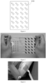
Figure 5 shows a photograph of a flexible electromyographic electrode array finally prepared in Example 1 of the present disclosure. -
Figure 6 shows a photograph of a collected electromyographic signal of biceps brachii in Example 1 of the present disclosure. -
Figure 7 shows a collected high-throughput electromyographic signal of biceps brachii in Example 1 of the present disclosure. -
Figure 8 shows an electrical signal collected after 20Hz high-throughput filtering in a comparative experiment of the present disclosure, where panel a shows the result from Comparative Example 1, and panel b shows the result from Example 1. -
Figure 9 shows a root mean square (RMS) value of noise (panel a) and a signal-to-noise ratio (SNR) (panel b) of the electrical signal shown inFigure 8 . -
Figure 10 shows a schematic principle diagram of noise generation during electrical signal detection shown inFigure 8 , where panel a shows the principle for Comparative Example 1, and panel b shows the principle for Example 1. - Reference signs:
flexible substrate 100, circuitboard connection pattern 110,wire 120,electrode contact 130, insulatinglayer 210,skin adhesive layer 220, circuit boardconnection mask pattern 310,wire mask pattern 320,contact mask pattern 330, throughhole 410. - The concept of the present disclosure and the technical effects produced by the present disclosure will be clearly and completely described below in conjunction with the embodiments to fully understand the purpose, features and effects of the present disclosure. Obviously, the described embodiments are only some of the embodiments of the present disclosure, but not all. Based on the embodiments of the present disclosure, other embodiments obtained by those skilled in the art without exerting creative efforts are all within the protection scope of the present disclosure.
- The embodiments of the present disclosure are described in detail below. The described embodiments are exemplary and only intended to explain the present disclosure and should not be understood as limiting the present disclosure.
- In the description of the present disclosure, "several" refers to one or more, "multiple" refers to two or more, "greater than", "less than", "exceeding", etc. are understood to exclude the indicated number, and "above", "below", "within", etc. are understood to include the indicated number. If there is a description of "first" and "second", it is only for the purpose of distinguishing technical features, and should not be understood as indicating or implying the relative importance or implicitly indicating the number of indicated technical features or implicitly indicating the order of indicated technical features.
- In the description of the present disclosure, the description of reference terms "an embodiment", "some embodiments", "an illustrative embodiment", "an example", "a specific example" or "some examples", etc. refer to specific feature, structure, material or characteristic described in conjunction with the embodiment or example and included in at least one embodiment or example of the present disclosure. In the description, schematic representations of the above terms do not necessarily refer to the same embodiment or example. Furthermore, the specific feature, structure, material or characteristic described may be combined in any suitable manner in any one or more embodiments or examples.
- Referring to
Figures 1 to 2, Figure 1 shows a schematic diagram of a flexible electromyographic electrode array according to an embodiment of the present disclosure, andFigure 2 shows a partial side view of the flexible electromyographic electrode array. The flexible electromyographic electrode array includes aflexible substrate 100; several liquid metal electrodes provided on theflexible substrate 100, wherein each of the liquid metal electrodes includes awire 120 and a circuitboard connection pattern 110 disposed at an end of thewire 120; andseveral electrode contacts 130 provided on theflexible substrate 100, wherein each of theelectrode contacts 130 is connected to the other end of thewire 120. Theelectrode contact 130, thewire 120 and the circuitconnection board pattern 110 constitute a complete electrical signal collection path. In some particular embodiments, theelectrode contact 130, thewire 120 and the circuitconnection board pattern 110 correspond to each other one-to-one, thereby forming several complete electrodes. Raw material of theelectrode contact 130 include a hydrophilic polymer and poly(3,4-ethylenedioxythiophene)/polystyrene sulfonate. The substrate, wire, circuit board connection pattern and electrode contact of the flexible electromyographic electrode array are all made of flexible materials, thereby ensuring the overall flexibility. The hydrophilic polymer and poly(3,4-ethylenedioxythiophene)/polystyrene sulfonate applied in theelectrode contact 130 bring a good flexibility and conductivity to the formed electrode contact, thus allowing a separate electrode contact to detect the electromyographic signal of a certain motor unit in the muscle. The flexibility of the material can also ensure the tight attachment between the electrode and the skin, without increasing the impedance of the electrode contact due to the loss of the moisture, thereby preventing the quality of signal recording from the generated noise. - In some particular embodiments, a mass ratio of the hydrophilic polymer to the poly(3,4-ethylenedioxythiophene)/polystyrene sulfonate in the raw material of the electrode contact is 1: (0.1 to 4). By controlling the ratio of the hydrophilic polymers to PEDOT: PSS, the flexibility and conductivity of the prepared electrode contact can be adjusted. In some preferred embodiments, the mass ratio is 1: (0.2 to 2); or further, the mass ratio is 1: (0.4 to 1), or 1: (0.4 to 0.6).
- In some particular embodiments, the raw material of the electrode contact further includes at least one of dimethyl sulfoxide, ethylene glycol, and glycidyloxypropyltrimethoxysilane. The dimethyl sulfoxide, ethylene glycol, and glycidyloxypropyltrimethoxysilane are added as dopants in components of contact solution to improve the final conductivity of the formed electrode contact and improve the signal quality.
- In some particular embodiments, the hydrophilic polymer is at least one selected from the group consisting of polyethylene glycol (PEG), polyethylene oxide (PEO), and polyvinyl alcohol (PVA). The combination of at least one of the above three polymers with PEDOT: PSS facilitates obtaining an electrode contact with good conductivity and flexibility.
- In some particular embodiments, the material applied for the flexible substrate is at least one of the well-known flexible polymer materials with good biocompatibility in the art, including polydimethylsiloxane, polylactic acid, polyimide, poly(lactic acid-co-glycolic acid), and polycaprolactone. In some particular embodiments, a thickness of the flexible substrate is 50 µm to 200 µm.
- In some particular embodiments, the material applied for the liquid metal electrode is at least one selected from the group consisting of gallium-indium alloy, gallium-indium-stannum alloy, bismuth-stannum alloy, and bismuth-stannum-plumbum-indium alloy. In some particular embodiments, a thickness of the liquid metal electrode is 500 nm to 2000 nm.
- In some particular embodiments, a size of the circuit board connection pattern is 1 mm to 10 mm. In some particular embodiments, a width of the wire is 50 µm to 1000 µm. In some particular embodiments, a distance d between the electrode contacts is 3 mm to 50 mm.
- In some particular embodiments, an insulating
layer 210 and askin adhesive layer 220 are provided on theflexible substrate 110 at positions other than the circuitboard connection patterns 110 and theelectrode contacts 130. The material of the insulatinglayer 210 includes at least one of silicon nitride, polydimethylsiloxane, and SU-8 photoresist. - The embodiments of the present disclosure further provide a preparation method for the above electromyographic electrode array. The preparation method includes the following steps:
- (1) coating a liquid metal ink onto a substrate material to form a liquid metal electrode pattern, wherein the liquid metal electrode pattern includes a wire, a circuit board connection pattern disposed at an end of the wire, and an electrode connection pattern disposed at the other end of the wire;
- (2) transfer-printing the liquid metal electrode pattern onto a flexible substrate to form several liquid metal electrodes; and
- (3) performing plasma cleaning on the electrode connection pattern by a mask plate to change hydrophilicity or hydrophobicity of position of the electrode connection pattern, and dripping raw material of electrode contact to form several electrode contacts.
- Referring to
Figure 3 , which shows a pattern mask plate of a liquid metal electrode used in some specific embodiments, the pattern mask plate includes a circuit boardconnection mask pattern 310 corresponding to the circuitboard connection pattern 110, awire mask pattern 320 corresponding to thewire 120, and acontact mask pattern 330 corresponding to theelectrode contacts 130. The liquid metal ink is printed onto the pattern mask plate to form a liquid metal electrode pattern. - In some particular embodiments, a flexible substrate material is continuously coated on the pattern mask plate printed to form the liquid metal electrode pattern, the flexible substrate material is peeled off after being dried and solidified to form the flexible substrate, thus transferring the liquid metal electrode pattern onto the flexible substrate to form several liquid metal electrodes. In order to ensure the integrity and accuracy of the pattern, screen printing can serve as the printing method.
- Referring to
Figure 4 , which is a schematic diagram of an electrode contact mask plate used in the preparation of an electrode contact in some embodiments, the electrode contact mask plate is provided with several throughholes 410 having the same shape as the electrode contact pattern. The electrode contact mask plate is covered onto the flexible substrate printed with the liquid metal electrode pattern, and plasma cleaning is performed thereon, thus changing the hydrophilicity or hydrophobicity of the surface at the position of the electrode contacts. After peeling off the electrode contact mask plate, contact solution prepared from the raw material of the electrode contact is dropped at the position. Due to the difference in hydrophilicity caused by plasma cleaning, the contact solution will automatically form the required electrode contact pattern, and the electrode contact will be formed after drying. - In some particular embodiments, a process of the encapsulation of the flexible electromyographic electrode array is further performed after forming the electrode contact. The encapsulation process includes covering the electrode contacts and the circuit board connection pattern with a baffle, performing encapsulation, and removing the baffle. In some preferred embodiments, the specific way of encapsulation includes performing encapsulation on the flexible substrate to form an insulating layer and a skin adhesive layer. In some preferred embodiments, an insulating material is used for primary encapsulation, a skin adhesive is used for secondary encapsulation after primary encapsulation, and the baffle is removed after encapsulation. Further, the electrode contact and the circuit board connection pattern are covered with the baffle, a PDMS solution (including PDMS and an appropriate amount of curing agent) is used for spin coating and encapsulation; after the spin coating is completed, the flexible electromyographic electrode array is dried to complete the primary encapsulation; then a flexible skin adhesive is used for spin coating and encapsulation; and after the spin coating is completed, the flexible electromyographic electrode array is dried to complete the secondary encapsulation, and the baffle is removed.
- The present disclosure further provides an electromyographic signal collection apparatus, which includes the above flexible electromyographic electrode array. In some particular embodiments, the electromyographic signal collection apparatus further includes a flexible circuit board, which is connected through a circuit board connection pattern on the flexible electromyographic electrode array. In some particular embodiments, the electromyographic signal collection apparatus further includes a receiving instrument, which is electrically connected to the flexible circuit board to collect the collected electromyographic signal.
- The present disclosure further provides an electrophysiological signal collection method, which uses the aforementioned flexible electromyographic electrode array to collect electrophysiological signal. The specific method includes covering the flexible electromyographic electrode array onto a skin surface of a subject, and acquiring a subcutaneous electromyographic signal.
- The present disclosure will be further described below through specific examples.
- A flexible electromyographic electrode array was provided in this example, with the preparation method as follows.
- (1) 3 g of gallium-indium alloy was weighted and added to 1 mL of n-decanol, and then a resulting mixture is subjected to an ultrasonic treatment for 1 min by an ultrasonic cell disrupter at 20% amplitude, so that the gallium-indium alloy was converted into micro-nano particles under an ultrasonic action, so as to prepare a liquid metal ink.
- (2) A pattern mask plate for liquid metal electrode of fully flexible surface electromyographic electrode was designed by Computer Aided Design (CAD). Referring to
Figure 3 , there were 24 contact mask patterns and circuit board connection mask patterns, where a side length of the contact mask patterns was 2.5 mm, a spacing therebetween was 15 mm; and a side length of the circuit board connection mask pattern was 5 mm, and a width of the wire mask pattern was 250 µm. The prepared liquid metal ink was printed into liquid metal electrode patterns on a polyethylene terephthalate (PET) film by a screen printing method with the mask plate. - (3) After the printed liquid metal electrode pattern was dried by baking for 2 min at 80 °C, PDMS (polydimethylsiloxane, purchased from Dow Corning with a brand name of Sylgard 184) solution (a mass ratio of PDMS to a curing agent was 10: 1) was spin-coated on the liquid metal electrode pattern, and the thickness of PDMS was controlled to be 50 µm. The liquid metal electrode pattern was baked for 20 min again at 80 °C, and peeled off after the PDMS solution was solidified; and the liquid metal electrode pattern was transfer-printed onto a PDMS flexible substrate.
- (4) 0.115 g of polyvinyl alcohol was dissolved in 5 mL of poly(3,4-ethylenedioxythiophene)/polystyrene sulfonate solution (PEDOT: PSS, 1.15 w/v%, a mass ratio of the polyvinyl alcohol to the PEDOT: PSS was approximately 2:1), 5% (v/v) dimethyl sulfoxide was added, and a resulting mixture was stirred for 4 h at 80 °C until a uniform and agglomeration-free PEDOT: PSS-PVA solution with good conductivity was obtained.
- (5) A silicone sheet (polydimethylsiloxane) and a paper cutter were used to make an electrode contact mask plate (refer to
Figure 4 ). The electrode contact mask plate was affixed to the electrode connection pattern position of the liquid metal electrode pattern, so that the through holes on the electrode contact mask plate correspond to the electrode connection pattern, and then plasma cleaning was performed. Due to the difference in hydrophilicity caused by plasma cleaning, the hydrophilicity and hydrophobicity of the electrode connection pattern position in the through holes were different from those around. After the mask plate was peeled off, the dripped PEDOT: PSS-PVA solution would automatically form the required electrode contact pattern. The amount of the PEDOT: PSS-PVA solution was controlled at 0.5 microliters per square millimeter to form a uniform conductive polymer film. After drying at 80 °C for 10 min, a flexible electromyographic electrode array with excellent conductivity and flexibility was obtained. - (6) A silicone sheet and a paper cutter were used to make baffles for encapsulating the electrode and the flexible circuit board connection point. The baffles were attached one by one to the electrode contact and the circuit board connection point pattern. The PDMS solution (a mass ratio of PDMS to a curing agent was 10:1) was used for spin coating and encapsulation, with a rotation speed being controlled at 2000 rpm and a rotation time of 30 s. After the spin coating was completed, the flexible electromyographic electrode array was baked at 80 °C for 10 min to complete a primary encapsulation. Then, a flexible skin adhesive (a mass ratio of component A to component B was 1:1, purchased from Dow Corning with a brand name of MG-9850) was used for spin coating and encapsulation, with the rotation speed being controlled at 2000 rpm and the rotation time of 30 s. After the spin coating was completed, the flexible electromyographic electrode array was dried at 80 °C for 10 min to complete a secondary encapsulation. The final product of the flexible electromyographic electrode array was then obtained by removing all the baffles with a tweezer, referring to the picture shown in
Figure 5 . Except for the electrode contacts and the circuit board connection point patterns, the rest of the product are sticky due to the presence of the flexible skin adhesive, so as to ensure continuous and stable contact among the device, the skin and the flexible circuit board. - Referring to
Figure 6 , the flexible electromyographic electrode array was attached to the biceps brachii. The flexible electromyographic electrode array transmitted the electromyographic signal to a receiving instrument through the contact between the circuit board connection pattern and the flexible circuit board, so that the electromyographic signal produced by the biceps brachii during contraction could be obtained. Referring toFigure 7 , through multi-channel signal collection by theelectrode contacts 1 to 24 in the array, specific information on muscle fiber activity and tendon extension could further be obtained therefrom. - Comparative Example 1: a commercial electrode (US 3M, 2228) was provided, and the difference of the commercial electrode as compared to Example 1 was that the electrode contact was made of Ag/AgCl.
- The flexible electromyographic electrode array provided in Example 1 and Comparative Example 1 were tested on frontalis muscle. One of the liquid metal electrodes and electrode contacts was used for the comparative experiment. The ground electrode of the flexible electromyographic electrode array was placed on the middle bone of the forehead, and the commercial electrode of Comparative Example 1 and the flexible electromyographic electrode array were placed on the left and right frontalis muscles respectively to conduct the frontalis muscle test. Electromyographic monitoring was bipolar monitoring (signals obtained from the working electrode and the ground electrode were differentiated), and the sampling rate was 1200 Hz. The subject performed an eyebrow-raising movement. The collected electrical signals were filtered by a 20Hz high-throughput filtering, and the results were shown in
Figure 8 , where panel a showed the result from Comparative Example 1, and panel b showed the result from Example 1. InFigure 9 , panel a showed the RMS value of noise in the electrical signal, and panel b showed the signal-to-noise ratio of the electrical signal, where the signal-to-noise ratio = 20 × logic (RMS signal/RMS noise). Referring to the experimental results inFigures 8 to 9 and the principle shown inFigure 10 (panel a showed the principle for Comparative Example 1, and panel b for Example 1), it was found that after only 4 eyebrow-raising movements, the electrode of Comparative Example 1 generated additional capacitance and resistance due to loss of flexibility and a gap on the skin, so that the overall circuit impedance was increased, and the signal was covered by the increased noise value, leading to an incapability of accurate measurement. In comparison, the electrode provided in Example 1 could be perfectly embedded in the skin folds, and after 33 eyebrow-raising movements (5 min of duration), stable baseline noise was still maintained, thus accurately reading signals. - A flexible electromyographic electrode array was provided in this example, which differed from Example 1 in that an equal mass of polyethylene oxide was used to replace polyvinyl alcohol. Using the method in the Comparative Experiment for detection, it was found that the stable baseline noise was still maintained after multiple eyebrow-raising movements, and the signal could be read accurately.
- A flexible electromyographic electrode array was provided in this example, which differed from Example 1 in that an equal mass of polyethylene glycol was used to replace polyvinyl alcohol. Using the method in the Comparative Experiment for detection, it was found that the stable baseline noise was still maintained after multiple eyebrow-raising movements, and the signal could be read accurately.
- A flexible electromyographic electrode array was provided in this example, which differed from Example 1 in that 0.115 g of polyvinyl alcohol was dissolved in 1 mL of poly(3,4-ethylenedioxythiophene)/polystyrene sulfonate solution (PEDOT: PSS, 1.15 w/v%). Using the method in the comparative experiment for detection, it was found that the stable baseline noise was still maintained after eyebrow-raising movements, and the signal could be read accurately.
- A flexible electromyographic electrode array was provided in this example, which differed from Example 1 in that 0.115 g of polyvinyl alcohol was dissolved in 40 mL of poly(3,4-ethylenedioxythiophene)/polystyrene sulfonate solution (PEDOT: PSS, 1.15 w/v%). Using the method in the comparative experiment for detection, it was found that the stable baseline noise was still maintained after eyebrow-raising movements, and the signal could be read accurately.
- A flexible electromyographic electrode array was provided in this example, which differed from Example 1 in that the spacing of the contact mask patterns was 5 mm, so that the spacing of electrode contacts in the finally prepared electrode array was 5 mm. Using the method in the comparative experiment for detection, it was found that the stable baseline noise was still maintained after eyebrow-raising movements, and the signal could be read accurately.
- A flexible electromyographic electrode array was provided in this example, which differed from Example 1 in that the spacing of the contact mask patterns was 30 mm, so that the spacing of electrode contacts in the finally prepared electrode array was 30 mm. Using the method in the comparative experiment for detection, it was found that the stable baseline noise was still maintained after eyebrow-raising movements, and the signal could be read accurately.
- The present disclosure has been described in detail above with reference to the embodiments. However, the present disclosure is not limited to the above-mentioned embodiments. Various changes can be made within the knowledge scope of those of ordinary skill in the art without departing from the purpose of the present disclosure. In addition, the embodiments of the present disclosure and the features in the embodiments may be combined with each other without conflict.
Claims (10)
- A flexible electromyographic electrode array, comprising:a flexible substrate;several liquid metal electrodes provided on the flexible substrate, wherein each of the liquid metal electrodes comprises a wire and a circuit board connection pattern disposed at an end of the wire; andseveral electrode contacts provided on the flexible substrate, wherein each of the electrode contacts is connected to the other end of the wire, and raw material of the electrode contact comprises a hydrophilic polymer and poly(3,4-ethylenedioxythiophene)/polystyrene sulfonate.
- The flexible electromyographic electrode array according to claim 1, wherein a mass ratio of the hydrophilic polymer to the poly(3,4-ethylenedioxythiophene)/polystyrene sulfonate is 1: (0.1 to 4).
- The flexible electromyographic electrode array according to claim 1, wherein the raw material of the electrode contact further comprises at least one of dimethyl sulfoxide, ethylene glycol, and glycidyloxypropyltrimethoxysilane.
- The flexible electromyographic electrode array according to claim 1, wherein the hydrophilic polymer is at least one selected from the group consisting of polyethylene glycol, polyethylene oxide, and polyvinyl alcohol.
- The flexible electromyographic electrode array according to any one of claims 1 to 4, wherein a skin adhesive layer is further provided on the flexible substrate.
- The flexible electromyographic electrode array according to any one of claims 1 to 4, wherein a spacing between the electrode contacts is 3 mm to 50 mm.
- A preparation method for the flexible electromyographic electrode array according to any one of claims 1 to 6, comprising the following steps:(1) coating a liquid metal ink onto a substrate material to form a liquid metal electrode pattern, wherein the liquid metal electrode pattern comprises a wire, a circuit board connection pattern disposed at an end of the wire, and an electrode connection pattern disposed at the other end of the wire;(2) transfer-printing the liquid metal electrode pattern onto a flexible substrate to form several liquid metal electrodes; and(3) performing plasma cleaning on the electrode connection pattern by a mask plate to change hydrophilicity or hydrophobicity of position of the electrode connection pattern, and dripping raw material of the electrode contact to form several electrode contacts.
- The preparation method according to claim 7, further comprising step (4): covering the electrode contacts and the circuit board connection pattern with a baffle, performing encapsulation, and removing the baffle.
- An electromyographic signal collection apparatus, comprising the flexible electromyographic electrode array according to any one of claims 1 to 6.
- An electrophysiological signal collection method, comprising covering the flexible electromyographic electrode array according to any one of claims 1 to 6 onto a skin surface of a subject, and acquiring an electromyographic signal.
Applications Claiming Priority (2)
| Application Number | Priority Date | Filing Date | Title |
|---|---|---|---|
| CN202111500574.1A CN114366110A (en) | 2021-12-09 | 2021-12-09 | Flexible myoelectric electrode array and preparation method and application thereof |
| PCT/CN2022/088644 WO2023103255A1 (en) | 2021-12-09 | 2022-04-24 | Flexible electromyographic electrode array, and preparation method therefor and application thereof |
Publications (2)
| Publication Number | Publication Date |
|---|---|
| EP4445844A1 true EP4445844A1 (en) | 2024-10-16 |
| EP4445844A4 EP4445844A4 (en) | 2025-04-09 |
Family
ID=81140337
Family Applications (1)
| Application Number | Title | Priority Date | Filing Date |
|---|---|---|---|
| EP22902695.0A Pending EP4445844A4 (en) | 2021-12-09 | 2022-04-24 | Flexible electromyographic electrode assembly and manufacturing method therefor and application thereof |
Country Status (4)
| Country | Link |
|---|---|
| US (1) | US20250064371A1 (en) |
| EP (1) | EP4445844A4 (en) |
| CN (1) | CN114366110A (en) |
| WO (1) | WO2023103255A1 (en) |
Families Citing this family (7)
| Publication number | Priority date | Publication date | Assignee | Title |
|---|---|---|---|---|
| CN114366110A (en) * | 2021-12-09 | 2022-04-19 | 南方科技大学 | Flexible myoelectric electrode array and preparation method and application thereof |
| CN115078487B (en) * | 2022-05-18 | 2024-04-19 | 厦门大学 | An in vitro myocardial flexible microelectrode array based on liquid metal and its preparation method |
| CN115624336B (en) * | 2022-09-27 | 2024-09-17 | 复旦大学 | Nuclear magnetic compatible nerve electrical stimulation-electrical recording system and preparation method thereof |
| EP4349259A1 (en) * | 2022-10-03 | 2024-04-10 | Technische Universität Graz | Electromyography device |
| CN118178855B (en) * | 2024-05-16 | 2024-09-10 | 哈尔滨工业大学(深圳)(哈尔滨工业大学深圳科技创新研究院) | Bioelectrode and preparation method and application thereof |
| CN119286001B (en) * | 2024-09-26 | 2026-01-06 | 南京理工大学 | Highly tensile and highly conductive hydrogels with layered structures, their preparation methods and applications |
| CN120052904B (en) * | 2025-04-27 | 2025-08-26 | 中国科学院深圳先进技术研究院 | A flexible electrode with real-time adjustable detection position |
Family Cites Families (16)
| Publication number | Priority date | Publication date | Assignee | Title |
|---|---|---|---|---|
| EP2513953B1 (en) * | 2009-12-16 | 2017-10-18 | The Board of Trustees of the University of Illionis | Electrophysiology using conformal electronics |
| US11567028B2 (en) * | 2015-11-29 | 2023-01-31 | Ramot At Tel-Aviv University Ltd. | Sensing electrode and method of fabricating the same |
| US11684305B2 (en) * | 2018-06-02 | 2023-06-27 | Seyedhesam Sadeghian-Motahar | Electrode array configuration on a flexible substrate for electro-oculogram recording |
| US11612344B2 (en) * | 2018-11-02 | 2023-03-28 | Biocircuit Technologies, Inc. | Electrode-based systems and devices for interfacing with biological tissue and related methods |
| CN111134401A (en) * | 2018-11-02 | 2020-05-12 | 国家纳米科学中心 | Highly elastic smart clothing based on liquid metal, its preparation method and application |
| CN109350847A (en) * | 2018-11-29 | 2019-02-19 | 深圳先进技术研究院 | A functionalized implantable flexible electrode and its application |
| EP3682941B1 (en) * | 2019-01-18 | 2021-11-10 | Ecole Polytechnique Federale De Lausanne (EPFL) EPFL-TTO | Biomedical device comprising a mechanically adaptive member |
| EP3705035A1 (en) * | 2019-03-07 | 2020-09-09 | Nederlandse Organisatie voor toegepast- natuurwetenschappelijk Onderzoek TNO | Manufacturing of skin-compatible electrodes |
| CN110251125A (en) * | 2019-07-12 | 2019-09-20 | 南方科技大学 | Flexible stretchable nerve electrode and preparation method and application thereof |
| JP2023504347A (en) * | 2019-10-11 | 2023-02-03 | ザ トラスティーズ オブ ザ ユニバーシティ オブ ペンシルバニア | Rapid manufacturing method for water-absorbing substrates for flexible sensors and conductors |
| KR102496236B1 (en) * | 2020-02-10 | 2023-02-03 | 서울시립대학교 산학협력단 | Transparent flexible bio-electrode and method for manufacturing the same |
| CN111920404A (en) * | 2020-08-03 | 2020-11-13 | 南方科技大学 | A flexible microelectrode array and its preparation method and application |
| CN112244839B (en) * | 2020-09-29 | 2022-03-25 | 中国科学院上海微系统与信息技术研究所 | Flexible electrode probe for long-term implantation and preparation method and equipment thereof |
| CN112545523B (en) * | 2020-12-04 | 2023-08-25 | 南方科技大学 | Liquid metal nerve electrode with adjustable hardness and preparation method and application thereof |
| CN113100773B (en) * | 2021-04-12 | 2024-11-12 | 中国科学院深圳先进技术研究院 | A method for preparing fiber membrane dry electrode by spinning directly on skin |
| CN114366110A (en) * | 2021-12-09 | 2022-04-19 | 南方科技大学 | Flexible myoelectric electrode array and preparation method and application thereof |
-
2021
- 2021-12-09 CN CN202111500574.1A patent/CN114366110A/en active Pending
-
2022
- 2022-04-24 US US18/717,530 patent/US20250064371A1/en active Pending
- 2022-04-24 EP EP22902695.0A patent/EP4445844A4/en active Pending
- 2022-04-24 WO PCT/CN2022/088644 patent/WO2023103255A1/en not_active Ceased
Also Published As
| Publication number | Publication date |
|---|---|
| EP4445844A4 (en) | 2025-04-09 |
| WO2023103255A1 (en) | 2023-06-15 |
| US20250064371A1 (en) | 2025-02-27 |
| CN114366110A (en) | 2022-04-19 |
Similar Documents
| Publication | Publication Date | Title |
|---|---|---|
| US20250064371A1 (en) | Flexible electromyographic electrode array, and preparation method therefor and application thereof | |
| DK2328989T3 (en) | Biomedical sensor system and method for detecting a time-varying signal | |
| CN109998533B (en) | Flexible microneedle electrode array device and preparation method | |
| CN108267078B (en) | Flexible wearable resistance-type strain sensor and preparation method thereof | |
| EP2892422B1 (en) | Electrode array and method of measuring using it | |
| CN104224170B (en) | A kind of array-type flexible surface myoelectric electrode and preparation method | |
| US20070276286A1 (en) | Device for Tissue Diagnosis and Spatial Tissue Mapping | |
| CN105342613A (en) | Flexible electrode for measuring muscle impedance and preparation method thereof | |
| JP2004504877A (en) | Electrode arrangement and sensor mounting system for non-invasive nerve location and imaging device | |
| CN108956737B (en) | Flexible microneedle sensor and its preparation method, three-dimensional three-dimensional electrode and package thereof | |
| KR20140099716A (en) | Sensor platform and method for preparing the same | |
| CN116898447A (en) | Multi-channel surface electromyography signal acquisition electrodes and systems for sarcopenia detection | |
| CN116942099B (en) | Swallowing monitoring system and method based on myoelectricity and pressure sensing | |
| CN118662137A (en) | Flexible implantation probe with variable rigidity and preparation method thereof | |
| CN117838134A (en) | A liquid metal flexible electrode and its preparation method and application | |
| CN112205986B (en) | Extensible electrode array for accurately positioning pelvic floor muscles and design method thereof | |
| Bocchino et al. | Development and characterization of passivation methods for microneedle-based biosensors | |
| WO2025000596A1 (en) | Pressure sensor, manufacturing method, and data acquisition system and method | |
| CN120078442A (en) | A flexible integrated array for myoelectric and ultrasonic collaborative sensing and its preparation method | |
| CN114469109A (en) | Microneedle brain electrode based on organic metal porous polymer and manufacturing method thereof | |
| CN118415645A (en) | Novel perianal electrode | |
| CN117812838A (en) | Flexible isotropic stretching electrode device and preparation method and application thereof | |
| Wang et al. | Multi-Channel flexible microneedle electrode array (MNEA) for high-density surface EMG recording | |
| Bocchino et al. | Strategies for passivating microneedle-based sensors: development, characterization and comparison | |
| CN117158983A (en) | Flexible array myoelectricity electrode and preparation method and application thereof |
Legal Events
| Date | Code | Title | Description |
|---|---|---|---|
| STAA | Information on the status of an ep patent application or granted ep patent |
Free format text: STATUS: THE INTERNATIONAL PUBLICATION HAS BEEN MADE |
|
| PUAI | Public reference made under article 153(3) epc to a published international application that has entered the european phase |
Free format text: ORIGINAL CODE: 0009012 |
|
| STAA | Information on the status of an ep patent application or granted ep patent |
Free format text: STATUS: REQUEST FOR EXAMINATION WAS MADE |
|
| 17P | Request for examination filed |
Effective date: 20240708 |
|
| AK | Designated contracting states |
Kind code of ref document: A1 Designated state(s): AL AT BE BG CH CY CZ DE DK EE ES FI FR GB GR HR HU IE IS IT LI LT LU LV MC MK MT NL NO PL PT RO RS SE SI SK SM TR |
|
| REG | Reference to a national code |
Ref country code: DE Ref legal event code: R079 Free format text: PREVIOUS MAIN CLASS: A61B0005296000 Ipc: A61B0005000000 |
|
| DAV | Request for validation of the european patent (deleted) | ||
| DAX | Request for extension of the european patent (deleted) | ||
| A4 | Supplementary search report drawn up and despatched |
Effective date: 20250310 |
|
| RIC1 | Information provided on ipc code assigned before grant |
Ipc: A61B 5/268 20210101ALI20250304BHEP Ipc: A61B 5/296 20210101ALI20250304BHEP Ipc: A61B 5/00 20060101AFI20250304BHEP |