EP4445842A1 - Biomagnetism measurement device - Google Patents
Biomagnetism measurement device Download PDFInfo
- Publication number
- EP4445842A1 EP4445842A1 EP22903916.9A EP22903916A EP4445842A1 EP 4445842 A1 EP4445842 A1 EP 4445842A1 EP 22903916 A EP22903916 A EP 22903916A EP 4445842 A1 EP4445842 A1 EP 4445842A1
- Authority
- EP
- European Patent Office
- Prior art keywords
- measurement
- biomagnetism
- measurement apparatus
- sensor
- content
- Prior art date
- Legal status (The legal status is an assumption and is not a legal conclusion. Google has not performed a legal analysis and makes no representation as to the accuracy of the status listed.)
- Pending
Links
Images



Classifications
-
- A—HUMAN NECESSITIES
- A61—MEDICAL OR VETERINARY SCIENCE; HYGIENE
- A61B—DIAGNOSIS; SURGERY; IDENTIFICATION
- A61B5/00—Measuring for diagnostic purposes; Identification of persons
- A61B5/24—Detecting, measuring or recording bioelectric or biomagnetic signals of the body or parts thereof
- A61B5/242—Detecting biomagnetic fields, e.g. magnetic fields produced by bioelectric currents
- A61B5/245—Detecting biomagnetic fields, e.g. magnetic fields produced by bioelectric currents specially adapted for magnetoencephalographic [MEG] signals
-
- A—HUMAN NECESSITIES
- A61—MEDICAL OR VETERINARY SCIENCE; HYGIENE
- A61B—DIAGNOSIS; SURGERY; IDENTIFICATION
- A61B5/00—Measuring for diagnostic purposes; Identification of persons
- A61B5/24—Detecting, measuring or recording bioelectric or biomagnetic signals of the body or parts thereof
- A61B5/242—Detecting biomagnetic fields, e.g. magnetic fields produced by bioelectric currents
-
- A—HUMAN NECESSITIES
- A61—MEDICAL OR VETERINARY SCIENCE; HYGIENE
- A61B—DIAGNOSIS; SURGERY; IDENTIFICATION
- A61B5/00—Measuring for diagnostic purposes; Identification of persons
- A61B5/68—Arrangements of detecting, measuring or recording means, e.g. sensors, in relation to patient
- A61B5/6801—Arrangements of detecting, measuring or recording means, e.g. sensors, in relation to patient specially adapted to be attached to or worn on the body surface
- A61B5/6802—Sensor mounted on worn items
- A61B5/6803—Head-worn items, e.g. helmets, masks, headphones or goggles
-
- A—HUMAN NECESSITIES
- A61—MEDICAL OR VETERINARY SCIENCE; HYGIENE
- A61B—DIAGNOSIS; SURGERY; IDENTIFICATION
- A61B5/00—Measuring for diagnostic purposes; Identification of persons
- A61B5/68—Arrangements of detecting, measuring or recording means, e.g. sensors, in relation to patient
- A61B5/6801—Arrangements of detecting, measuring or recording means, e.g. sensors, in relation to patient specially adapted to be attached to or worn on the body surface
- A61B5/6813—Specially adapted to be attached to a specific body part
- A61B5/6814—Head
-
- A—HUMAN NECESSITIES
- A61—MEDICAL OR VETERINARY SCIENCE; HYGIENE
- A61B—DIAGNOSIS; SURGERY; IDENTIFICATION
- A61B5/00—Measuring for diagnostic purposes; Identification of persons
- A61B5/74—Details of notification to user or communication with user or patient; User input means
- A61B5/742—Details of notification to user or communication with user or patient; User input means using visual displays
-
- A—HUMAN NECESSITIES
- A61—MEDICAL OR VETERINARY SCIENCE; HYGIENE
- A61B—DIAGNOSIS; SURGERY; IDENTIFICATION
- A61B5/00—Measuring for diagnostic purposes; Identification of persons
- A61B5/74—Details of notification to user or communication with user or patient; User input means
- A61B5/742—Details of notification to user or communication with user or patient; User input means using visual displays
- A61B5/7435—Displaying user selection data, e.g. icons in a graphical user interface
-
- A—HUMAN NECESSITIES
- A61—MEDICAL OR VETERINARY SCIENCE; HYGIENE
- A61B—DIAGNOSIS; SURGERY; IDENTIFICATION
- A61B5/00—Measuring for diagnostic purposes; Identification of persons
- A61B5/74—Details of notification to user or communication with user or patient; User input means
- A61B5/7475—User input or interface means, e.g. keyboard, pointing device, joystick
-
- A—HUMAN NECESSITIES
- A61—MEDICAL OR VETERINARY SCIENCE; HYGIENE
- A61B—DIAGNOSIS; SURGERY; IDENTIFICATION
- A61B2562/00—Details of sensors; Constructional details of sensor housings or probes; Accessories for sensors
- A61B2562/02—Details of sensors specially adapted for in-vivo measurements
- A61B2562/0223—Magnetic field sensors
-
- A—HUMAN NECESSITIES
- A61—MEDICAL OR VETERINARY SCIENCE; HYGIENE
- A61B—DIAGNOSIS; SURGERY; IDENTIFICATION
- A61B2562/00—Details of sensors; Constructional details of sensor housings or probes; Accessories for sensors
- A61B2562/04—Arrangements of multiple sensors of the same type
- A61B2562/046—Arrangements of multiple sensors of the same type in a matrix array
-
- A—HUMAN NECESSITIES
- A61—MEDICAL OR VETERINARY SCIENCE; HYGIENE
- A61B—DIAGNOSIS; SURGERY; IDENTIFICATION
- A61B2562/00—Details of sensors; Constructional details of sensor housings or probes; Accessories for sensors
- A61B2562/22—Arrangements of medical sensors with cables or leads; Connectors or couplings specifically adapted for medical sensors
- A61B2562/225—Connectors or couplings
- A61B2562/226—Connectors or couplings comprising means for identifying the connector, e.g. to prevent incorrect connection to socket
-
- A—HUMAN NECESSITIES
- A61—MEDICAL OR VETERINARY SCIENCE; HYGIENE
- A61B—DIAGNOSIS; SURGERY; IDENTIFICATION
- A61B5/00—Measuring for diagnostic purposes; Identification of persons
- A61B5/103—Measuring devices for testing the shape, pattern, colour, size or movement of the body or parts thereof, for diagnostic purposes
- A61B5/107—Measuring physical dimensions, e.g. size of the entire body or parts thereof
- A61B5/1072—Measuring physical dimensions, e.g. size of the entire body or parts thereof measuring distances on the body, e.g. measuring length, height or thickness
Definitions
- the present invention relates to a biomagnetism measurement apparatus.
- a biomagnetism measurement apparatus capable of detecting weak magnetism emitted from a subject and, for example, visualizing a distribution of a magnetic field is expected to be able to perform measurement for various purposes.
- Such a biomagnetism measurement apparatus includes a plurality of sensors, and acquires a distribution of a magnetic field in a subject based on a signal output from each sensor.
- Patent Literature 1 JP 2021-148409 A
- the present invention has been made in view of such circumstances, and an object of the present invention is to provide a biomagnetism measurement apparatus in which an arrangement of sensors is considered in accordance with the purpose of the measurement to be performed.
- the biomagnetism measurement apparatus comprising:
- a biomagnetism measurement apparatus of the present invention includes an arithmetic device that acquires an arrangement pattern of the magnetic sensor group corresponding to a content of the measurement based on information indicating the content of the measurement.
- the arrangement of the sensors is sufficiently considered according to the purpose of the measurement.
- a biomagnetism measurement apparatus 1 includes a helmet 2 that covers the head of a subject and a plurality of sensors 3 that are inserted into any one of a plurality of through holes 2a provided in the helmet 2.
- the sensors 3 have such high sensitivity that biomagnetism can be detected, and can be attached to and detached from the helmet 2.
- an optical pumping module capable of sensing biomagnetism at room temperature can be applied.
- another configuration such as a diamond quantum sensor may be used for the sensor 3.
- the through holes 2a of the helmet 2 are numbered from the necessity of distinction.
- the sensors 3 are numbered from the necessity of distinction.
- the biomagnetism measurement apparatus 1 includes an input unit 11 that causes a user to input information indicating the content of measurement and clinical information of a subject, an arithmetic device 12 that acquires an arrangement pattern of the sensor 3 corresponding to the information indicating the content of measurement and the clinical information of the subject, a storage unit 13 that stores a table to be referred to when the arithmetic device 12 operates, and a monitor 14 that displays the arrangement pattern.
- the biomagnetism measurement apparatus 1 includes an image generation unit 21 that images the output of each of the sensors 3. An image such as a magnetoencephalography generated by the image generation unit 21 is displayed on the monitor 14 described above.
- the arithmetic device 12 and the image generation unit 21 are implemented by a central processing unit (CPU) executing various programs. Each unit may be realized by a single CPU or may be realized by a plurality of independent processors.
- the storage unit 13 stores not only the above-described table but also various types of information necessary for the operation of the biomagnetism measurement apparatus 1. Each of the units 12 and 21 operates by acquiring these pieces of information.
- the biomagnetism measurement apparatus 1 is characterized in that measurement for various purposes can be performed.
- the biomagnetism measurement apparatus 1 since the arrangement of the sensors 3 suitable for measurement changes according to the purpose of the measurement, the biomagnetism measurement apparatus 1 according to the embodiment makes the positions of the sensors 3 variable so that the arrangement of the sensors 3 with respect to the subject can be changed. That is, the sensors 3 of the embodiment are inserted into the through holes 2a of the helmet 2 according to the purpose of the measurement. In this way, each sensor 3 can be appropriately arranged according to the purpose of the measurement.
- the image generation unit 21 at the time of executing a specific measurement operates on the assumption that each sensor 3 is disposed on the helmet 2 on the basis of, for example, only one attaching method among the plurality of methods. Since only one sensor 3 can be inserted into each through hole 2a, it is assumed that a sensor 3 having a number corresponding to the number of the through hole 2a is inserted into the through hole 2a in the case of performing specific measurement.
- the image generation unit 21 at the time of executing a measurement different from the specific measurement may operate on the assumption that each sensor 3 is disposed in each through hole 2a on the basis of an attaching method different from the specific measurement.
- the correspondence relationship between the number of the through hole 2a and the number of the sensor 3 in the attaching method at this time is not necessarily the same as the correspondence relationship at the time of performing the specific measurement described above.
- the attaching method of each sensor 3 corresponding to the content of the measurement can be displayed on a display screen 14a of the monitor 14.
- the biomagnetism measurement apparatus 1 displays an attaching method of the sensor 3 on the display screen 14a.
- a user Before attaching each sensor 3 to the helmet 2, a user inputs information indicating the content of the measurement to the biomagnetism measurement apparatus 1 through the input unit 11. At this point, the user inputs the information regarding the content of the measurement to the biomagnetism measurement apparatus 1 while referring to the display screen 14a of the monitor 14. As illustrated in FIG. 2 , the display screen 14a at this time displays a setting screen including a section 31a of "number of sensors to be used", a section 3 1b of "task” which is the content of measurement, a section 31c of "head size” which is the clinical information of the subject, and a section 31d of "head shape” which is the clinical information of the subject.
- the number of sensors to be used, the task, the head size, and the head shape are examples of information indicating the content of measurement in the present embodiment that affects the attaching method of the sensor 3 to the helmet 2.
- An input box 32a on which the user can input specific information regarding the item is displayed around the section 31a of "number of sensors to be used" on the display screen 14a.
- an input box 32b on which the user can input information regarding the task is displayed around the item 3 1b of "task” on the display screen 14a
- an input box 32c in which the user can input information regarding the head size is displayed around the item 31c of "head size” on the display screen 14a.
- an input box 32d on which the user can input information regarding the head shape is displayed around the item 31d of "head shape” on the display screen 14a.
- the task of the present embodiment will be described.
- a predetermined problem may be imposed on the subject.
- Specific examples of the task include a problem of opening and closing the eyes of the subject under measurement, a problem of appreciating a specific video, and a problem of listening to a specific sound.
- the task is a measurement type when a predetermined problem is imposed. Therefore, a corresponding problem is set in each of the tasks.
- the information regarding the number of sensors input by the user to the biomagnetism measurement apparatus 1 through the input unit 11 indicates the number of sensors used at the time of measurement, and the user can increase or decrease the number of sensors used for measurement according to the purpose of the measurement.
- the information regarding the task input by the user to the biomagnetism measurement apparatus 1 through the input unit 11 indicates a task corresponding to a problem performed at the time of measurement, and the user can select the number of sensors to be used for measurement according to the purpose of the measurement.
- the information regarding the head size and head shape input by the user to the biomagnetism measurement apparatus 1 through the input unit 11 indicates, for example, the type of helmet used for measurement.
- the user may input various types of information through a keyboard attached to the input unit 11, or the user may select a target item from a pull-down menu displayed on the input boxes 32a, 32b, 32c, and 32d through a pointing device attached to the input unit 11.
- a confirm button 33 displayed on the display screen 14a is used after the user completes the input of each item.
- the input operation of the user is completed, and the information indicating the content of the measurement input by the user is sent to the arithmetic device 12.
- the arithmetic device 12 receives the information indicating the content of the measurement and outputs the information regarding the attaching method of the sensor 3 suitable for the measurement.
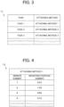
- FIG. 3 illustrates a table T1 referred to by the arithmetic device 12 at the time of operation. In the present embodiment, for convenience of description, it is assumed that the user can select only the task.
- the arithmetic device 12 outputs an attaching method of the sensor 3 corresponding to the task on the basis of the acquired information regarding the task.
- the attaching method corresponds to the arrangement pattern of the present invention.
- a table T2 illustrated in FIG. 4 is also referred to by the arithmetic device 12.
- the arithmetic device 12 that has recognized an appropriate sensor attaching method refers to the table T2 this time, and grasps a correspondence relationship between a sensor number specifically indicating the recognized attaching method and a mounting position number for identifying each of the through holes 2a of the helmet 2.
- the table of FIG. 4 illustrates a correspondence relationship related to the attaching method 1.
- the storage unit 13 stores a table similar to that in FIG. 4 for all the attaching methods illustrated in the table T1, and the arithmetic device 12 operates with reference to a table indicating an attaching method corresponding to a task selected by the user among the plurality of tables.
- the storage unit 13 stores a relevant table corresponding to the table T1. Therefore, the arithmetic device 12 of the present embodiment can grasp an appropriate attaching method for items other than the task by the same operation as in the case of the task. Since the table T2 is created for each attaching method and stored in the storage unit 13, the arithmetic device 12 can recognize the correspondence relationship between the appropriate sensor number and mounting position number by the operation similar to the case of the task when acquiring the attaching method. Note that a term relating to the type of the helmet 2 may be provided on the table T2, and the arithmetic device 12 may recognize an appropriate type of the helmet 2 in accordance with the setting of the "head size" and the "head shape" by the user.
- the arithmetic device 12 transmits the acquired information regarding the correspondence relationship to the monitor 14. As illustrated in FIG. 5 , the monitor displays the contents of the table T2 on the display screen 14a. The user inserts each of the sensors 3 into the through hole 2a of the helmet 2 with reference to the display content. In this way, in the biomagnetism measurement apparatus 1 according to the embodiment, the arrangement of the sensors 3 used for measurement can be made appropriate according to the content of the measurement.
- the storage unit 13 that stores the table in which the information indicating the content of the measurement and the arrangement pattern are associated with each other, the operation of the arithmetic device 12 becomes more reliable.
Landscapes
- Health & Medical Sciences (AREA)
- Life Sciences & Earth Sciences (AREA)
- Engineering & Computer Science (AREA)
- Medical Informatics (AREA)
- Surgery (AREA)
- Biophysics (AREA)
- Biomedical Technology (AREA)
- Heart & Thoracic Surgery (AREA)
- Physics & Mathematics (AREA)
- Molecular Biology (AREA)
- Pathology (AREA)
- Animal Behavior & Ethology (AREA)
- General Health & Medical Sciences (AREA)
- Public Health (AREA)
- Veterinary Medicine (AREA)
- Human Computer Interaction (AREA)
- Measurement And Recording Of Electrical Phenomena And Electrical Characteristics Of The Living Body (AREA)
- Measurement Of The Respiration, Hearing Ability, Form, And Blood Characteristics Of Living Organisms (AREA)
Abstract
Description
- The present invention relates to a biomagnetism measurement apparatus.
- A biomagnetism measurement apparatus capable of detecting weak magnetism emitted from a subject and, for example, visualizing a distribution of a magnetic field is expected to be able to perform measurement for various purposes. Such a biomagnetism measurement apparatus includes a plurality of sensors, and acquires a distribution of a magnetic field in a subject based on a signal output from each sensor.
- However, in the conventional biomagnetism measurement apparatus, it is not sufficiently considered that optimal arrangement of the sensors with respect to the subject varies depending on the purpose of the measurement.
- The present invention has been made in view of such circumstances, and an object of the present invention is to provide a biomagnetism measurement apparatus in which an arrangement of sensors is considered in accordance with the purpose of the measurement to be performed.
- In order to achieve such an object, the present invention has the following configuration. That is, the biomagnetism measurement apparatus comprising:
- a group of magnetic sensors that are disposed outside a body of a subject and configured to measure biomagnetism of the subject; and
- a processor configured to acquire, based on information indicating the content of the measurement, an arrangement pattern of the group of magnetic sensors such that the arrangement pattern corresponds to a content of the measurement to be performed.
- A biomagnetism measurement apparatus of the present invention includes an arithmetic device that acquires an arrangement pattern of the magnetic sensor group corresponding to a content of the measurement based on information indicating the content of the measurement. In the biomagnetism measurement apparatus of the present invention, the arrangement of the sensors is sufficiently considered according to the purpose of the measurement.
-
-
FIG. 1 is a functional block diagram illustrating a configuration of a biomagnetism measurement apparatus according to an embodiment. -
FIG. 2 is a schematic diagram illustrating an input of information indicating a content of measurement according to the embodiment. -
FIG. 3 is a table referred to by an arrangement information output unit according to the embodiment. -
FIG. 4 is a table referred to by the arrangement information output unit according to the embodiment. -
FIG. 5 is a schematic diagram illustrating an output of an arrangement pattern according to the embodiment. -
FIG. 6 is a schematic diagram illustrating an output of an arrangement pattern according to a modification. -
FIG. 7 is a schematic diagram illustrating an example of an arrangement pattern. - Hereinafter, a biomagnetism measurement apparatus according to an embodiment will be described with reference to the drawings. A
biomagnetism measurement apparatus 1 according to the embodiment includes ahelmet 2 that covers the head of a subject and a plurality ofsensors 3 that are inserted into any one of a plurality of throughholes 2a provided in thehelmet 2. Thesensors 3 have such high sensitivity that biomagnetism can be detected, and can be attached to and detached from thehelmet 2. Specifically, as thesensor 3, for example, an optical pumping module capable of sensing biomagnetism at room temperature can be applied. In addition, another configuration such as a diamond quantum sensor may be used for thesensor 3. The throughholes 2a of thehelmet 2 are numbered from the necessity of distinction. Similarly, thesensors 3 are numbered from the necessity of distinction. - The
biomagnetism measurement apparatus 1 includes aninput unit 11 that causes a user to input information indicating the content of measurement and clinical information of a subject, anarithmetic device 12 that acquires an arrangement pattern of thesensor 3 corresponding to the information indicating the content of measurement and the clinical information of the subject, astorage unit 13 that stores a table to be referred to when thearithmetic device 12 operates, and amonitor 14 that displays the arrangement pattern. In addition, thebiomagnetism measurement apparatus 1 includes animage generation unit 21 that images the output of each of thesensors 3. An image such as a magnetoencephalography generated by theimage generation unit 21 is displayed on themonitor 14 described above. - The
arithmetic device 12 and theimage generation unit 21 are implemented by a central processing unit (CPU) executing various programs. Each unit may be realized by a single CPU or may be realized by a plurality of independent processors. In addition, thestorage unit 13 stores not only the above-described table but also various types of information necessary for the operation of thebiomagnetism measurement apparatus 1. Each of theunits - The
biomagnetism measurement apparatus 1 is characterized in that measurement for various purposes can be performed. When biomagnetism is measured, since the arrangement of thesensors 3 suitable for measurement changes according to the purpose of the measurement, thebiomagnetism measurement apparatus 1 according to the embodiment makes the positions of thesensors 3 variable so that the arrangement of thesensors 3 with respect to the subject can be changed. That is, thesensors 3 of the embodiment are inserted into the throughholes 2a of thehelmet 2 according to the purpose of the measurement. In this way, eachsensor 3 can be appropriately arranged according to the purpose of the measurement. - In a case where the
sensors 3 is simply attached to thehelmet 2, there are many attaching methods of thesensors 3 to thehelmet 2 conceivable. However, theimage generation unit 21 at the time of executing a specific measurement operates on the assumption that eachsensor 3 is disposed on thehelmet 2 on the basis of, for example, only one attaching method among the plurality of methods. Since only onesensor 3 can be inserted into each throughhole 2a, it is assumed that asensor 3 having a number corresponding to the number of thethrough hole 2a is inserted into thethrough hole 2a in the case of performing specific measurement. In addition, theimage generation unit 21 at the time of executing a measurement different from the specific measurement may operate on the assumption that eachsensor 3 is disposed in each throughhole 2a on the basis of an attaching method different from the specific measurement. The correspondence relationship between the number of the throughhole 2a and the number of thesensor 3 in the attaching method at this time is not necessarily the same as the correspondence relationship at the time of performing the specific measurement described above. - In the configuration of the embodiment, when the information indicating the content of the measurement is acquired, the attaching method of each
sensor 3 corresponding to the content of the measurement can be displayed on adisplay screen 14a of themonitor 14. Hereinafter, an operation when thebiomagnetism measurement apparatus 1 displays an attaching method of thesensor 3 on thedisplay screen 14a will be described. - First, before attaching each
sensor 3 to thehelmet 2, a user inputs information indicating the content of the measurement to thebiomagnetism measurement apparatus 1 through theinput unit 11. At this point, the user inputs the information regarding the content of the measurement to thebiomagnetism measurement apparatus 1 while referring to thedisplay screen 14a of themonitor 14. As illustrated inFIG. 2 , thedisplay screen 14a at this time displays a setting screen including asection 31a of "number of sensors to be used", asection 3 1b of "task" which is the content of measurement, asection 31c of "head size" which is the clinical information of the subject, and asection 31d of "head shape" which is the clinical information of the subject. The number of sensors to be used, the task, the head size, and the head shape are examples of information indicating the content of measurement in the present embodiment that affects the attaching method of thesensor 3 to thehelmet 2. Aninput box 32a on which the user can input specific information regarding the item is displayed around thesection 31a of "number of sensors to be used" on thedisplay screen 14a. Similarly, aninput box 32b on which the user can input information regarding the task is displayed around theitem 3 1b of "task" on thedisplay screen 14a, and aninput box 32c in which the user can input information regarding the head size is displayed around theitem 31c of "head size" on thedisplay screen 14a. Then, aninput box 32d on which the user can input information regarding the head shape is displayed around theitem 31d of "head shape" on thedisplay screen 14a. - The task of the present embodiment will be described. When biomagnetism of a subject is measured using the
biomagnetism measurement apparatus 1, a predetermined problem may be imposed on the subject. Specific examples of the task include a problem of opening and closing the eyes of the subject under measurement, a problem of appreciating a specific video, and a problem of listening to a specific sound. The task is a measurement type when a predetermined problem is imposed. Therefore, a corresponding problem is set in each of the tasks. - Hereinafter, information indicating the content of measurement will be described. The information regarding the number of sensors input by the user to the
biomagnetism measurement apparatus 1 through theinput unit 11 indicates the number of sensors used at the time of measurement, and the user can increase or decrease the number of sensors used for measurement according to the purpose of the measurement. - The information regarding the task input by the user to the
biomagnetism measurement apparatus 1 through theinput unit 11 indicates a task corresponding to a problem performed at the time of measurement, and the user can select the number of sensors to be used for measurement according to the purpose of the measurement. - The information regarding the head size and head shape input by the user to the
biomagnetism measurement apparatus 1 through theinput unit 11 indicates, for example, the type of helmet used for measurement. - As a specific configuration of the
input boxes input unit 11, or the user may select a target item from a pull-down menu displayed on theinput boxes input unit 11. - A
confirm button 33 displayed on thedisplay screen 14a is used after the user completes the input of each item. When an operation is performed on theconfirm button 33, the input operation of the user is completed, and the information indicating the content of the measurement input by the user is sent to thearithmetic device 12. - The
arithmetic device 12 receives the information indicating the content of the measurement and outputs the information regarding the attaching method of thesensor 3 suitable for the measurement.FIG. 3 illustrates a table T1 referred to by thearithmetic device 12 at the time of operation. In the present embodiment, for convenience of description, it is assumed that the user can select only the task. Thearithmetic device 12 outputs an attaching method of thesensor 3 corresponding to the task on the basis of the acquired information regarding the task. The attaching method corresponds to the arrangement pattern of the present invention. - In the table T1 referred to by the
arithmetic device 12, various tasks and an optimal attaching method of thesensor 3 are associated with each other. For example, when the user selects thetask 1 through theinput unit 11, thearithmetic device 12 recognizes that an appropriate attaching method of thesensor 3 is an attachingmethod 1. - A table T2 illustrated in
FIG. 4 is also referred to by thearithmetic device 12. Thearithmetic device 12 that has recognized an appropriate sensor attaching method refers to the table T2 this time, and grasps a correspondence relationship between a sensor number specifically indicating the recognized attaching method and a mounting position number for identifying each of the throughholes 2a of thehelmet 2. In this example, since the attachingmethod 1 is an appropriate selection, the table ofFIG. 4 illustrates a correspondence relationship related to the attachingmethod 1. However, in practice, thestorage unit 13 stores a table similar to that inFIG. 4 for all the attaching methods illustrated in the table T1, and thearithmetic device 12 operates with reference to a table indicating an attaching method corresponding to a task selected by the user among the plurality of tables. - Note that, for the setting items other than the task described with reference to
FIG. 2 , similarly to the case of the task, thestorage unit 13 stores a relevant table corresponding to the table T1. Therefore, thearithmetic device 12 of the present embodiment can grasp an appropriate attaching method for items other than the task by the same operation as in the case of the task. Since the table T2 is created for each attaching method and stored in thestorage unit 13, thearithmetic device 12 can recognize the correspondence relationship between the appropriate sensor number and mounting position number by the operation similar to the case of the task when acquiring the attaching method. Note that a term relating to the type of thehelmet 2 may be provided on the table T2, and thearithmetic device 12 may recognize an appropriate type of thehelmet 2 in accordance with the setting of the "head size" and the "head shape" by the user. - The
arithmetic device 12 transmits the acquired information regarding the correspondence relationship to themonitor 14. As illustrated inFIG. 5 , the monitor displays the contents of the table T2 on thedisplay screen 14a. The user inserts each of thesensors 3 into the throughhole 2a of thehelmet 2 with reference to the display content. In this way, in thebiomagnetism measurement apparatus 1 according to the embodiment, the arrangement of thesensors 3 used for measurement can be made appropriate according to the content of the measurement. - Hereinafter, a configuration and an effect of the
biomagnetism measurement apparatus 1 in this example will be described. - (1) The biomagnetism measurement apparatus of this example includes: a magnetic sensor group that is disposed outside a body of a subject and measures biomagnetism of the subject; and an
arithmetic device 12 that acquires an arrangement pattern of the magnetic sensor group corresponding to a content of the measurement based on information indicating the content of the measurement.
As described above, by providing thearithmetic device 12 that acquires the arrangement pattern of the magnetic sensor group corresponding to the content of the measurement based on the information indicating the content of the measurement, thebiomagnetism measurement apparatus 1 that can optimize the arrangement of the sensors according to the purpose of the measurement can be provided. - (2) The biomagnetism measurement apparatus according to (1), further includes a display unit that displays the arrangement pattern acquired by the
arithmetic device 12.
As described above, by providing the display unit that displays the arrangement pattern acquired by thearithmetic device 12, it is possible to provide thebiomagnetism measurement apparatus 1 in which the user can easily grasp the arrangement pattern. - (3) In the biomagnetism measurement apparatus according to (1) or (2), the
arithmetic device 12 acquires the arrangement pattern based on the information indicating a content of the measurement or clinical information of the subject.
As described above, if thearithmetic device 12 acquires the arrangement pattern based on the information indicating the content of the measurement or the clinical information of the subject, it is possible to provide thebiomagnetism measurement apparatus 1 that can instantaneously acquire the optimal arrangement of thesensors 3 that differs depending on the content of the measurement and the clinical information of the subject. - (4) The biomagnetism measurement apparatus according to any one of (1) to (3) further includes an
input unit 11 that receives the information indicating a content of the measurement from a user.
As described above, if theinput unit 11 that receives the information indicating the content of the measurement from the user is provided, the user can instantaneously acquire the arrangement of thesensors 3 that matches the content of the measurement. - (5) The biomagnetism measurement apparatus according to (1) to (4) further includes a
helmet 2 that holds themagnetic sensor 3 and is mounted on the subject, in which the information regarding the arrangement pattern is information regarding an attaching method when thesensor 3 is attached to thehelmet 2.
As described above, if the information regarding the arrangement pattern is information regarding an attaching method when thesensor 3 is attached to thehelmet 2 mounted on the subject with thesensor 3 disposed, the user can instantaneously grasp the attaching method of thesensor 3 to thehelmet 2. - (6) In the biomagnetism measurement apparatus according to (5), the information regarding the arrangement pattern includes information regarding a correspondence relationship between a
specific sensor 3 and a specific mounting position on thehelmet 2.
As described above, if the information regarding the arrangement pattern includes the information regarding the correspondence relationship between thespecific sensor 3 and the specific mounting position on thehelmet 2, the user can instantaneously understand the correspondence relationship between the sensor number and the mounting position number. - (7) The biomagnetism measurement apparatus according to any one of (1) to (6) further includes a drive unit that receives the arrangement pattern acquired by the
arithmetic device 12 and moves thesensor 3. Details of this example will be described later.
As described above, by providing the drive unit that receives the arrangement pattern output from thearithmetic device 12 and moves thesensor 3, the arrangement of thesensor 3 is optimized according to the purpose of the measurement even if the user does not manually move thesensor 3. - (8) The biomagnetism measurement apparatus according to any one of (1) to (7) further includes a
storage unit 13 that stores a table in which the information indicating the content of the measurement and the arrangement pattern are associated with each other. - As described above, by providing the
storage unit 13 that stores the table in which the information indicating the content of the measurement and the arrangement pattern are associated with each other, the operation of thearithmetic device 12 becomes more reliable. - Note that the embodiment disclosed herein is illustrative in all respects and is not restrictive. The scope of the present invention includes the claims and all modifications within the meaning and scope equivalent to the claims. As an example, the present invention can be modified as follows.
-
- (1) In the above-described embodiment, the
sensor 3 is mounted on thehelmet 2 manually by the user, but this may be automatic. Thebiomagnetism measurement apparatus 1 having such a configuration includes a mechanism for inserting thesensor 3 into the throughhole 2a of thehelmet 2. That is, according to the present modification, the drive unit that drives thesensor 3 is provided, and the drive unit receives the information regarding the attaching method of thesensor 3 output from thearithmetic device 12 and moves thesensor 3. In the present modification, it is not always necessary to display the information regarding the attaching method of thesensor 3 on thedisplay screen 14a of themonitor 14. - (2) In the above-described embodiment, the correspondence relationship between the sensor number and the mounting position number is displayed on the
display screen 14a of themonitor 14, but the present invention is not limited to this configuration. The present invention can also be applied to a configuration in which it is not necessary to distinguish thesensors 3. When eachsensor 3 of the present modification is inserted into the throughhole 2a in thehelmet 2, thesensor 3 can acquire the mounting position number of the throughhole 2a into which eachsensor 3 is inserted based on an identification unit provided in the throughhole 2a. Eachsensor 3 grasps its own position in thehelmet 2 according to the acquired mounting position number, and outputs information regarding the mounting position number to theimage generation unit 21. Eachsensor 3 is assigned a sensor number so that theimage generation unit 21 can distinguish thesensor 3, and eachsensor 3 transmits its own sensor number together with the mounting position number to theimage generation unit 21. As a result, theimage generation unit 21 can operate while grasping the correspondence relationship between the sensor number and the mounting position number. As the identification unit provided in the throughhole 2a, a tag (for example, a barcode) or the like can be applied. In this example, thesensor 3 includes a scanner that reads a barcode, and operates by reading the barcode provided on the inner wall of the throughhole 2a.
In this example, since it is not necessary to distinguish thesensors 3 and mount thesensors 3 on thehelmet 2, the content of the table displayed on thedisplay screen 14a of themonitor 14 is only the information regarding the mounting position as illustrated inFIG. 6 . Therefore, the table stored in thestorage unit 13 is similar to this, and the terms of the sensor numbers of the table T2 illustrated inFIG. 4 are omitted. - (3) In the setting screen of the content of the measurement described in
FIG. 2 of the above-described embodiment, for example, a task may be omitted. That is, the present invention can also be applied to a device that measures biomagnetism in a stable state in which no problem is imposed on a subject. The same applies to the other terms "number of sensors to be used", "head size", and "head shape" described inFIG. 2 . In addition, as the content of the measurement, for example, a setting item not illustrated inFIG. 2 such as "disease state" may be added to the content of the measurement. - (4) In the above-described embodiment, the contents of the table T2 stored in the
storage unit 13 are displayed on thedisplay screen 14a of themonitor 14, but the present invention is not limited to this configuration. Thearithmetic device 12 may edit the table T2 on the basis of information such as "head size" and" head shape", and transmit the edited table to themonitor 14. With this configuration, it is not necessary to prepare a table in advance for all conceivable cases, and a biomagnetism measurement apparatus having excellent flexibility can be provided. - (5) In the above-described embodiment, the contents of the table T2 stored in the
storage unit 13 are displayed on thedisplay screen 14a of themonitor 14, but the present invention is not limited to this configuration. The shape of thehelmet 2 and the positions of the throughholes 2a in thehelmet 2 may be stored in thestorage unit 13, and thearithmetic device 12 may generate a table on the basis of information such as "head size" and" head shape". With this configuration, it is not necessary to prepare a table in advance for all conceivable cases, and a biomagnetism measurement apparatus having excellent flexibility can be provided. - (6) In
FIG. 1 , thesensor 3 is not mounted on all of the throughholes 2a. This indicates a mounting status of thesensor 3 when a predetermined task or the like is executed, and it is also conceivable that thesensor 3 is mounted on all of the throughholes 2a for measurement depending on the task or the like. In addition, even in a case where thesensor 3 is not mounted on all the throughholes 2a, the position of the throughhole 2a into which thesensor 3 is not inserted may not be as illustrated inFIG. 1 depending on a task or the like. In addition, the number of throughholes 2a, the number ofsensors 3, and the like in thehelmet 2 are all examples.FIG. 7 illustrates positions of the throughholes 2a and thesensors 3 when the top of the subject is looked down, and illustrates arrangement of thesensors 3 in a task A and arrangement of the sensors in a task B. That is, in the task A, thesensors 3 are arranged in a 3 × 3 two-dimensional matrix on the left side and the right side of thehelmet 2. On the other hand, in the task B, thesensors 3 are disposed at the top of thehelmet 2 and front, rear, left, and right positions surrounding the top, and thesensors 3 are disposed at the rear of thehelmet 2 and front, rear, left, and right positions surrounding the rear. - (7) Although the above-described embodiment has a configuration related to a magnetoencephalography, the present invention can also be applied to an apparatus capable of generating an image other than a magnetoencephalography, such as a magnetocardiogram.
-
- 3
- sensor (magnetic sensor)
- 11
- input unit
- 12
- arrangement information output unit
Claims (8)
- A biomagnetism measurement apparatus comprising:a group of magnetic sensors that are disposed outside a body of a subject and configured to measure biomagnetism of the subject; anda processor configured to acquire, based on information indicating the content of the measurement, an arrangement pattern of the group of magnetic sensors such that the arrangement pattern corresponds to a content of the measurement to be performed.
- The biomagnetism measurement apparatus according to claim 1, further comprising a display unit that displays the arrangement pattern acquired by the arithmetic device.
- The biomagnetism measurement apparatus according to claim 1, wherein the arithmetic device acquires the arrangement pattern based on the information indicating a content of the measurement or clinical information of the subject.
- The biomagnetism measurement apparatus according to claim 1, further comprising an input unit that receives the information indicating the content of the measurement from a user.
- The biomagnetism measurement apparatus according to claim 1, further comprising a support that holds the magnetic sensor and is mounted on the subject,
wherein the information regarding the arrangement pattern is information regarding an attaching method when the magnetic sensor is attached to the support. - The biomagnetism measurement apparatus according to claim 5, wherein the information regarding the arrangement pattern includes information regarding a correspondence relationship between a specific magnetic sensor and a specific mounting position on the support.
- The biomagnetism measurement apparatus according to claim 1, further comprising a drive unit that receives the arrangement pattern acquired by the arithmetic device and moves the magnetic sensor.
- The biomagnetism measurement apparatus according to claim 1, further comprising a storage unit that stores a table in which the information indicating the content of the measurement and the arrangement pattern are associated with each other.
Applications Claiming Priority (2)
| Application Number | Priority Date | Filing Date | Title |
|---|---|---|---|
| JP2021200993 | 2021-12-10 | ||
| PCT/JP2022/040419 WO2023105984A1 (en) | 2021-12-10 | 2022-10-28 | Biomagnetism measurement device |
Publications (2)
| Publication Number | Publication Date |
|---|---|
| EP4445842A1 true EP4445842A1 (en) | 2024-10-16 |
| EP4445842A4 EP4445842A4 (en) | 2025-06-18 |
Family
ID=86730161
Family Applications (1)
| Application Number | Title | Priority Date | Filing Date |
|---|---|---|---|
| EP22903916.9A Pending EP4445842A4 (en) | 2021-12-10 | 2022-10-28 | BIOMAGNETISM MEASURING DEVICE |
Country Status (5)
| Country | Link |
|---|---|
| US (1) | US20250241574A1 (en) |
| EP (1) | EP4445842A4 (en) |
| JP (1) | JP7609303B2 (en) |
| CN (1) | CN118042983A (en) |
| WO (1) | WO2023105984A1 (en) |
Family Cites Families (10)
| Publication number | Priority date | Publication date | Assignee | Title |
|---|---|---|---|---|
| US4846190A (en) * | 1983-08-23 | 1989-07-11 | John Erwin R | Electroencephalographic system data display |
| FI964387A0 (en) * | 1996-10-30 | 1996-10-30 | Risto Ilmoniemi | Foerfarande och anordning Foer kartlaeggning av kontakter inom hjaernbarken |
| CN109414212B (en) * | 2016-06-03 | 2023-03-21 | 国立大学法人东京医科齿科大学 | Biomagnetic measuring device |
| CN109561848B (en) * | 2016-08-02 | 2023-03-10 | 国立大学法人东京医科齿科大学 | Biomagnetic measuring device |
| EP3685743B1 (en) * | 2017-10-16 | 2022-07-20 | National University Corporation Tokyo Medical and Dental University | Biomagnetism measurement device |
| US11237712B2 (en) * | 2017-10-31 | 2022-02-01 | Ricoh Company, Ltd. | Information processing device, biomedical-signal measuring system, display method, and recording medium storing program code |
| CN109620201B (en) * | 2018-12-07 | 2023-04-14 | 南京国科精准医学科技有限公司 | Flexible multi-lead cap-type magnetoencephalometer and its high-precision imaging method |
| US11497425B2 (en) * | 2019-03-08 | 2022-11-15 | Asahi Kasei Microdevices Corporation | Magnetic field measurement apparatus |
| JP2020168138A (en) | 2019-04-02 | 2020-10-15 | 株式会社リコー | Magnetic measuring device and head-mounted magnetic measuring device |
| JP7366817B2 (en) | 2020-03-23 | 2023-10-23 | 株式会社リコー | Helium circulation system, cryogenic freezing method, and biomagnetic measurement device |
-
2022
- 2022-10-28 WO PCT/JP2022/040419 patent/WO2023105984A1/en not_active Ceased
- 2022-10-28 JP JP2023566156A patent/JP7609303B2/en active Active
- 2022-10-28 US US18/703,774 patent/US20250241574A1/en active Pending
- 2022-10-28 CN CN202280065458.8A patent/CN118042983A/en active Pending
- 2022-10-28 EP EP22903916.9A patent/EP4445842A4/en active Pending
Also Published As
| Publication number | Publication date |
|---|---|
| JPWO2023105984A1 (en) | 2023-06-15 |
| EP4445842A4 (en) | 2025-06-18 |
| JP7609303B2 (en) | 2025-01-07 |
| US20250241574A1 (en) | 2025-07-31 |
| CN118042983A (en) | 2024-05-14 |
| WO2023105984A1 (en) | 2023-06-15 |
Similar Documents
| Publication | Publication Date | Title |
|---|---|---|
| JP6005848B2 (en) | How to assist in finding the desired item in storage | |
| RU2597492C2 (en) | Method of facilitating detection of object in place of storage | |
| JP5616953B2 (en) | Digital signage system | |
| US8274532B2 (en) | System for adaptively orienting a display image on a device | |
| US20210248579A1 (en) | Apparatus and method for visually identifying an item selected from a stock of items | |
| JP2008246126A (en) | Motor function measuring sensor, motor function measuring device and motor function analyzing device | |
| JP2013182326A (en) | Information processor, store system and program | |
| JP2017007861A (en) | Image processor | |
| JP2011078640A (en) | Biological information monitoring system and nursing support program | |
| JP6661698B2 (en) | POS system | |
| EP4133988A1 (en) | Endoscope insertion assistance device, method, and non-temporary computer-readable medium having program stored therein | |
| EP4445842A1 (en) | Biomagnetism measurement device | |
| ES2926330T3 (en) | weighing machine | |
| JPH11513602A (en) | Imaging system for medical diagnostic equipment | |
| JP2006101630A (en) | Apparatus layout display system and apparatus layout display method | |
| EP4461203A1 (en) | Medical information processing system, medical information processing method, and program | |
| JP7671859B2 (en) | Contents providing device | |
| JP7673840B2 (en) | Shelf label management system, shelf label management method, and program | |
| US20260069122A1 (en) | Computer-readable medium for frame image extraction | |
| JP7239731B2 (en) | Weighing devices and weighing systems | |
| JP2020141834A (en) | Endoscope processor and endoscope system | |
| JP7467075B2 (en) | Information processing device and program | |
| CN108572030A (en) | Temperature and thermal map system | |
| JPWO2024095674A5 (en) | ||
| JP2018016493A (en) | Work support device and program |
Legal Events
| Date | Code | Title | Description |
|---|---|---|---|
| STAA | Information on the status of an ep patent application or granted ep patent |
Free format text: STATUS: THE INTERNATIONAL PUBLICATION HAS BEEN MADE |
|
| PUAI | Public reference made under article 153(3) epc to a published international application that has entered the european phase |
Free format text: ORIGINAL CODE: 0009012 |
|
| STAA | Information on the status of an ep patent application or granted ep patent |
Free format text: STATUS: REQUEST FOR EXAMINATION WAS MADE |
|
| 17P | Request for examination filed |
Effective date: 20240520 |
|
| AK | Designated contracting states |
Kind code of ref document: A1 Designated state(s): AL AT BE BG CH CY CZ DE DK EE ES FI FR GB GR HR HU IE IS IT LI LT LU LV MC ME MK MT NL NO PL PT RO RS SE SI SK SM TR |
|
| DAV | Request for validation of the european patent (deleted) | ||
| DAX | Request for extension of the european patent (deleted) | ||
| A4 | Supplementary search report drawn up and despatched |
Effective date: 20250521 |
|
| RIC1 | Information provided on ipc code assigned before grant |
Ipc: A61B 5/107 20060101ALN20250515BHEP Ipc: A61B 5/245 20210101AFI20250515BHEP |