EP4445775A1 - Aerosol generation system - Google Patents
Aerosol generation system Download PDFInfo
- Publication number
- EP4445775A1 EP4445775A1 EP21967154.2A EP21967154A EP4445775A1 EP 4445775 A1 EP4445775 A1 EP 4445775A1 EP 21967154 A EP21967154 A EP 21967154A EP 4445775 A1 EP4445775 A1 EP 4445775A1
- Authority
- EP
- European Patent Office
- Prior art keywords
- heat generator
- resistive heat
- generation system
- aerosol generation
- metal plates
- Prior art date
- Legal status (The legal status is an assumption and is not a legal conclusion. Google has not performed a legal analysis and makes no representation as to the accuracy of the status listed.)
- Pending
Links
Images




Classifications
-
- A—HUMAN NECESSITIES
- A24—TOBACCO; CIGARS; CIGARETTES; SIMULATED SMOKING DEVICES; SMOKERS' REQUISITES
- A24F—SMOKERS' REQUISITES; MATCH BOXES; SIMULATED SMOKING DEVICES
- A24F40/00—Electrically operated smoking devices; Component parts thereof; Manufacture thereof; Maintenance or testing thereof; Charging means specially adapted therefor
- A24F40/40—Constructional details, e.g. connection of cartridges and battery parts
- A24F40/46—Shape or structure of electric heating means
-
- A—HUMAN NECESSITIES
- A24—TOBACCO; CIGARS; CIGARETTES; SIMULATED SMOKING DEVICES; SMOKERS' REQUISITES
- A24F—SMOKERS' REQUISITES; MATCH BOXES; SIMULATED SMOKING DEVICES
- A24F40/00—Electrically operated smoking devices; Component parts thereof; Manufacture thereof; Maintenance or testing thereof; Charging means specially adapted therefor
- A24F40/20—Devices using solid inhalable precursors
-
- A—HUMAN NECESSITIES
- A24—TOBACCO; CIGARS; CIGARETTES; SIMULATED SMOKING DEVICES; SMOKERS' REQUISITES
- A24F—SMOKERS' REQUISITES; MATCH BOXES; SIMULATED SMOKING DEVICES
- A24F40/00—Electrically operated smoking devices; Component parts thereof; Manufacture thereof; Maintenance or testing thereof; Charging means specially adapted therefor
- A24F40/40—Constructional details, e.g. connection of cartridges and battery parts
-
- A—HUMAN NECESSITIES
- A24—TOBACCO; CIGARS; CIGARETTES; SIMULATED SMOKING DEVICES; SMOKERS' REQUISITES
- A24F—SMOKERS' REQUISITES; MATCH BOXES; SIMULATED SMOKING DEVICES
- A24F47/00—Smokers' requisites not otherwise provided for
-
- H—ELECTRICITY
- H05—ELECTRIC TECHNIQUES NOT OTHERWISE PROVIDED FOR
- H05B—ELECTRIC HEATING; ELECTRIC LIGHT SOURCES NOT OTHERWISE PROVIDED FOR; CIRCUIT ARRANGEMENTS FOR ELECTRIC LIGHT SOURCES, IN GENERAL
- H05B3/00—Ohmic-resistance heating
- H05B3/10—Heating elements characterised by the composition or nature of the materials or by the arrangement of the conductor
- H05B3/12—Heating elements characterised by the composition or nature of the materials or by the arrangement of the conductor characterised by the composition or nature of the conductive material
-
- A—HUMAN NECESSITIES
- A24—TOBACCO; CIGARS; CIGARETTES; SIMULATED SMOKING DEVICES; SMOKERS' REQUISITES
- A24F—SMOKERS' REQUISITES; MATCH BOXES; SIMULATED SMOKING DEVICES
- A24F40/00—Electrically operated smoking devices; Component parts thereof; Manufacture thereof; Maintenance or testing thereof; Charging means specially adapted therefor
- A24F40/50—Control or monitoring
- A24F40/51—Arrangement of sensors
Definitions
- the present invention relates to aerosol generation systems.
- Inhaler devices including electronic cigarettes and nebulizers that generate material to be inhaled by users are becoming widely popular.
- Such an inhaler device uses an aerosol source for generating an aerosol and a flavor source for imparting a flavor component to the generated aerosol, so as to be capable of generating a flavor-component-imparted aerosol.
- a user can taste the flavor by inhaling the flavor-component-imparted aerosol generated by the inhaler device.
- Patent Literature 1 indicated below discloses a blade-shaped heater that is inserted into the stick-shaped substrate to heat the substrate from the inside thereof.
- Patent Literature 1 CN 209807157 U
- the present invention has been made in view of the above problem, and an object of the present invention is to provide a new and improved aerosol generation system that can suppress transmission of heat produced from the heater to areas other than the aerosol generating substrate.
- an aspect of the present invention provides an aerosol generation system including: a resistive heat generator that heats an aerosol generating substrate from an inside thereof; and a pair of metal plates provided at opposite surfaces of the resistive heat generator.
- the pair of metal plates each include a first region and a second region.
- the first region is where the metal plates face each other with the resistive heat generator interposed therebetween in a thickness direction of the resistive heat generator.
- the second region is where the metal plates do not face each other with the resistive heat generator interposed therebetween in the thickness direction of the resistive heat generator.
- the first regions may be provided toward a leading end of the resistive heat generator to be inserted into the aerosol generating substrate, and the second regions may be provided toward a trailing end opposite the leading end.
- the second regions may be provided as partial cut-outs of the metal plates such that the metal plates do not face each other with the resistive heat generator interposed therebetween in the thickness direction of the resistive heat generator
- the pair of metal plates in the second regions may be partially cut out such that edges of the metal plates remain, the edges being located diagonally from each other in a cross-sectional shape of the resistive heat generator.
- the metal plates cut out in the second regions may have a rectangular shape.
- a securing section having an insertion section into which the metal plates and the resistive heat generator are inserted may be further provided.
- the securing section secures the metal plates and the resistive heat generator to a housing.
- the metal plates in the second regions and the resistive heat generator may be inserted into the insertion section.
- the securing section may be composed of a super engineering plastic material.
- the securing section may have a circular or rectangular tabular shape.
- Each of the metal plates may be composed of a nickel-containing iron alloy.
- the resistive heat generator may have a tabular shape.
- a thickness of the tabular shape may be smaller than 1/4 of a width of the tabular shape.
- the aerosol generating substrate into which the resistive heat generator and the metal plates are inserted may be further provided.
- At least one of the metal plates may include a rib formed by bending an edge of the metal plate along an outer shape of the resistive heat generator from the opposite surfaces of the resistive heat generator
- the resistive heat generator may have an angularly protruding shape toward a leading end to be inserted into the aerosol generating substrate.
- At least one of the metal plates may further include a leading-end rib formed by bending an edge of the metal plate along the shape at the leading end of the resistive heat generator
- the resistive heat generator and the metal plates may be adhered together by using a conductive adhesive paste.
- the resistive heat generator may be a PTC heater.
- the resistive heat generator may contain barium titanate.
- a temperature of heat generated by the resistive heat generator may be below 350°C.
- An inhaler device generates an aerosol by heating a substrate containing an aerosol source from inside the substrate.
- the present configuration example will be described below with reference to FIG. 1 .
- FIG. 1 is a schematic diagram schematically illustrating the configuration example of the inhaler device.
- an inhaler device 100 according to this configuration example includes a power supply 111, a sensor 112, a notifier 113, a memory 114, a communicator 115, a controller 116, a heater 121, and a container 140.
- inhalation is performed by a user in a state where a stick substrate 150 is accommodated in the container 140.
- the structural elements will be sequentially described below.
- the inhaler device 100 and the stick substrate 150 operate in cooperation with each other to generate the aerosol to be inhaled by the user. Therefore, the combination of the inhaler device 100 and the stick substrate 150 may be regarded as an aerosol generation system.
- the power supply 111 stores electric power.
- the power supply 111 supplies the electric power to the structural elements of the inhaler device 100.
- the power supply 111 may be a rechargeable battery, such as a lithium ion secondary battery.
- the power supply 111 may be recharged by being connected to an external power supply by, for example, a USB (universal serial bus) cable.
- the power supply 111 may be recharged in a non-connected state with a power-transmitting device by wireless power transmission technology.
- the power supply 111 may be removable from the inhaler device 100 so as to be replaceable with a new power supply 111.
- the sensor 112 detects various types of information regarding the inhaler device 100, and outputs the detected information to the controller 116.
- the sensor 112 may be a pressure sensor such as a microphone condenser, a flow sensor, or a temperature sensor. When detecting a numerical value generated in accordance with the user's inhalation, the pressure sensor, the flow sensor, or the temperature sensor can output information indicating that the inhalation has been performed by the user to the controller 116.
- the sensor 112 may be an input device, such as a button or a switch, receiving information input by the user.
- the sensor 112 may include a command button for starting/stopping aerosol generation.
- the input device that receives information input by the user can output the information input by the user to the controller 116.
- the sensor 112 may be a temperature sensor that detects the temperature of the heater 121. For example, by detecting the temperature of the heater 121 based on an electrical resistance value of the heater 121, the temperature sensor can determine the temperature of the stick substrate 150 accommodated in the container 140.
- the notifier 113 notifies the user of information.
- the notifier 113 is a light-emitting device, such as an LED (light-emitting diode). Accordingly, when the power supply 111 needs to be recharged, when the power supply 111 is being recharged, or when an abnormality has occurred in the inhaler device 100, the notifier 113 can emit light in different patterns of light, respectively. Each pattern of light is a concept involving colors and on/off timings. Together with or in place of the light-emitting device, the notifier 113 may be, for example, a display device that displays an image, a sound output device that outputs sound, and a vibration device that vibrates. The notifier 113 may also provide notification information indicating that inhalation by the user is possible. The notification information indicating that inhalation by the user is possible may be provided when the temperature of the stick substrate 150 heated by the heater 121 reaches a predetermined temperature.
- the memory 114 stores various types of information for operation of the inhaler device 100.
- the memory 114 is, for example, a non-volatile storage medium, such as a flash memory.
- An example of the information stored in the memory 114 is information regarding the OS (operating system) of the inhaler device 100, such as the control information about the various types of structural elements controlled by the controller 116.
- Another example of the information stored in the memory 114 is information regarding inhalation by the user, such as the number of times of inhalation, the inhalation time, and the accumulated inhalation time period.
- the communicator 115 is a communication interface for exchanging information between the inhaler device 100 and another device.
- the communicator 115 performs communication in conformity with any wired or wireless communication standard.
- a communication standard may be, for example, a wireless LAN (local area network), a wired LAN, Wi-Fi (registered trademark), or Bluetooth (registered trademark).
- the communicator 115 may transmit the information regarding the inhalation by the user to a smartphone to cause the smartphone to display the information regarding the inhalation by the user.
- the communicator 115 may receive information about a new OS from a server to update the information about the OS stored in the memory 114.
- the controller 116 functions as an arithmetic processing unit and a control device, and controls the overall operation in the inhaler device 100 in accordance with various programs.
- the controller 116 is implemented by an electronic circuit, such as a CPU (central processing unit) or a microprocessor.
- the controller 116 may include a ROM (read only memory) that stores a program and arithmetic parameter to be used, and a RAM (random access memory) that temporarily stores an appropriately changing parameter.
- the inhaler device 100 executes various processes based on control by the controller 116.
- Examples of the processes controlled by the controller 116 include supplying of electric power from the power supply 111 to the other structural elements, recharging of the power supply 111, detection of information by the sensor 112, notification of information by the notifier 113, storing and reading of information by the memory 114, and exchanging of information by the communicator 115.
- Other processes executed by the inhaler device 100 such as an input of information to each structural element and a process based on information output from each structural element, are also controlled by the controller 116.
- the container 140 has an internal space 141 and holds the stick substrate 150 while accommodating a portion of the stick substrate 150 within the internal space 141.
- the container 140 has an opening 142 through which the internal space 141 communicates with the outside, and holds the stick substrate 150 inserted in the internal space 141 through the opening 142.
- the container 140 is a tubular body having the opening 142 and a bottom 143 as a bottom surface, and defines the internal space 141 that is pillar-shaped.
- the container 140 has an inside diameter smaller than an outside diameter of the stick substrate 150 in at least a portion of the tubular body in the height direction, and may hold the stick substrate 150 while applying pressure around the stick substrate 150 inserted in the internal space 141.
- the container 140 also has a function for defining a flow path for air traveling through the stick substrate 150.
- An air inlet serving as an inlet for the air entering the flow path is disposed in, for example, the bottom 143.
- an air outlet serving as an outlet for the air exiting from the flow path is the opening 142.
- the stick substrate 150 is a stick-shaped aerosol generating substrate.
- the stick substrate 150 includes a substrate 151 and an inhalation port 152.
- the substrate 151 contains an aerosol source.
- the aerosol source atomizes by being heated, so that an aerosol is generated.
- the aerosol source may include, for example, a material derived from tobacco, such as a product obtained by forming shredded tobacco or tobacco raw material into a granular form, a sheet form, or a powder form.
- the aerosol source may also include a material not derived from tobacco and made from a plant (such as mint or herb) other than tobacco. If the inhaler device 100 is a medical inhaler, the aerosol source may include a medicine to be inhaled by a patient.
- the aerosol source is not limited to a solid and may be a liquid, such as polyhydric alcohol, including glycerine or propylene glycol, or water. At least a portion of the substrate 151 is accommodated in the internal space 141 of the container 140 in the state where the stick substrate 150 is held by the container 140.
- the inhalation port 152 is a member to be held in the user's mouth during inhalation. At least a portion of the inhalation port 152 protrudes from the opening 142 in the state where the stick substrate 150 is held by the container 140.
- the heater 121 heats the aerosol source so as to atomize the aerosol source and generate the aerosol.
- the heater 121 is blade-shaped and is disposed to protrude from the bottom 143 of the container 140 to the internal space 141 of the container 140. Therefore, when the stick substrate 150 is inserted into the container 140, the blade-shaped heater 121 is inserted into the stick substrate 150 to pierce the substrate 151 of the stick substrate 150.
- the heater 121 produces heat, the aerosol source contained in the stick substrate 150 atomizes by being heated from inside the stick substrate 150, whereby the aerosol is generated.
- the heater 121 produces heat when supplied with electric power from the power supply 111.
- the heater 121 supplied with the electric power produces heat.
- the aerosol is generated from the stick substrate 150.
- the inhaler device 100 allows for inhalation by the user.
- the supply of electric power to the heater 121 may be stopped.
- the aerosol may be generated by the heater 121 supplied with the electric power
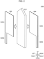
- FIG. 2 is an exploded perspective view of a heater body 1250 included in the heater 121.
- FIG. 3 is a perspective view of the heater 121 including the heater body 1250 illustrated in FIG. 2 .
- the heater body 1250 includes a resistive heat generator 1210, a first metal plate 1220, and a second metal plate 1230.
- the heater body 1250 can heat the stick substrate 150 from the inside thereof by using heat generated from the resistive heat generator 1210 supplied with electricity via the first metal plate 1220 and the second metal plate 1230.
- the heater body 1250 in which the resistive heat generator 1210, the first metal plate 1220, and the second metal plate 1230 are bonded together is secured to, for example, a housing of the inhaler device 100 by being held by a securing section 1260.
- the heater 121 is constituted of the heater body 1250 and the securing section 1260.
- a direction in which the leading end of the heater body 1250 is inserted into the stick substrate 150 may also be referred to as "up direction”, and a direction opposite the up direction may also be referred to as “down direction”.
- a direction in which the first metal plate 1220, the resistive heat generator 1210, and the second metal plate 1230 are bonded together may also be referred to as "front-rear direction”, and a direction orthogonal to the up-down direction and the front-rear direction may also be referred to as "left-right direction”.
- a PTC heater uses a resistor having properties (PTC properties) in which an electrical resistance value increases significantly when the temperature reaches a predetermined temperature (referred to as "Curie temperature”) such that an electric current does not flow therethrough.
- PTC properties a resistor having properties
- a PTC heater can control the amount of supplied electricity without having to use a control device, so as to be capable of controlling the heating temperature below the Curie temperature. Therefore, a PTC heater can heat a target below the Curie temperature.
- the resistive heat generator 1210 may be a PTC heater with barium titanate (BaTiO 3 ) having the PTC properties as the resistor. In such a case, the resistive heat generator 1210 can set the Curie temperature of the barium titanate to 350°C, so as to be capable of heating the stick substrate 150 to a temperature below 350°C.
- the resistive heat generator 1210 may have a long tabular shape extending in the up-down direction. Specifically, the longitudinal direction of the long shape of the resistive heat generator 1210 corresponds to the up-down direction, whereas the lateral direction of the long shape corresponds to the left-right direction.
- the resistive heat generator 1210 has a rectangular cross-sectional shape that is orthogonal to the longitudinal direction (i.e., the up-down direction) of the long shape. Accordingly, as compared with a case where the resistive heat generator 1210 has a circular cross-sectional shape with the same surface area, the cross-sectional shape can have a longer perimeter.
- the resistive heat generator 1210 at the leading end to be inserted into the stick substrate 150 may have an angularly protruding shape toward the leading end (i.e., in the up direction).
- the angular shape extending toward the leading end may have an acute angle, a right angle, or an obtuse angle.
- the resistive heat generator 1210 may have a pentagonal tabular shape whose apex exists at the leading end (i.e., the upper end) to be inserted into the stick substrate 150 and that extends in the up-down direction.
- the leading end (i.e., the upper end) thereof to be inserted into the stick substrate 150 has a pointy shape like a sword tip, so that the heater 121 can be inserted into the stick substrate 150 more readily.
- the first metal plate 1220 and the second metal plate 1230 are bonded to the resistive heat generator 1210 by using a conductive adhesive paste, so that electricity can be supplied to the resistive heat generator 1210.
- a conductive adhesive paste that can be used is a so-called anisotropic conductive adhesive having conductive particles uniformly distributed within an epoxy-based adhesive.
- the first metal plate 1220 and the second metal plate 1230 may be composed of metal with a low thermal expansion coefficient.
- the first metal plate 1220 and the second metal plate 1230 may be composed of a nickel (Ni) containing iron alloy with a low thermal expansion coefficient, such as Invar (registered trademark). Accordingly, delamination of the first metal plate 1220 and the second metal plate 1230 from the resistive heat generator 1210 due to thermal expansion occurring when the resistive heat generator 1210 generates heat can be suppressed.
- the first metal plate 1220 includes a first region 1220A and a second region 1220B that are arranged in the longitudinal direction.
- the second metal plate 1230 includes a first region 1230A and a second region 1230B that are arranged in the longitudinal direction.
- the distance between the first metal plate 1220 and the second metal plate 1230 may be substantially equal to the thickness of the resistive heat generator 1210 in the front-rear direction. Therefore, in the first regions 1220A and 1230A, the distance between the first metal plate 1220 and the second metal plate 1230 is relatively short, so that the electrical resistance value between the first metal plate 1220 and the second metal plate 1230 is reduced, whereby a large amount of electric current flows therebetween. Accordingly, in the first regions 1220A and 1230A, the amount of heat generated by the resistive heat generator 1210 is relatively large.
- the second regions 1220B and 1230B are regions not facing each other with the resistive heat generator 1210 interposed therebetween in the thickness direction of the resistive heat generator 1210.
- the second regions 1220B and 1230B are partially-cut-out regions of the first metal plate 1220 and the second metal plate 1230 such as not to face each other with the resistive heat generator 1210 interposed therebetween in the thickness direction of the resistive heat generator 1210.
- first metal plate 1220 and the second metal plate 1230 in the second regions 1220B and 1230B may be cut out such that edges located diagonally from each other in the cross-sectional shape (i.e., the rectangular shape) of the resistive heat generator 1210 in the thickness direction remain.
- first metal plate 1220 in the second region 1220B may have a rectangular region cut out therefrom such that a left edge thereof remains.
- the second metal plate 1230 in the second region 1230B may have a rectangular region cut out therefrom such that a right edge thereof remains.
- the distance between the first metal plate 1220 and the second metal plate 1230 is substantially equal to the length of a diagonal line of the cross-sectional shape (i.e., the rectangular shape) of the resistive heat generator 1210. Therefore, in the second regions 1220B and 1230B, the distance between the first metal plate 1220 and the second metal plate 1230 is relatively long, so that the electrical resistance value between the first metal plate 1220 and the second metal plate 1230 is increased, whereby electric current is less likely to flow therebetween. Accordingly, in the second regions 1220B and 1230B, the amount of heat generated by the resistive heat generator 1210 is relatively small.
- the amount of heat generated by the resistive heat generator 1210 can be adjusted by adjusting the distances between the first regions 1220A and 1230A and the second regions 1220B and 1230B.
- the amount of heat generated by the resistive heat generator 1210 in the first regions 1220A and 1230A at the leading end i.e., the upper side
- the amount of heat generated by the resistive heat generator 1210 in the second regions 1220B and 1230B at the trailing end i.e., the lower side
- the heater body 1250 can heat the stick substrate 150 more efficiently.
- the trailing ends of the first metal plate 1220 and the second metal plate 1230 may each have a length equal to that of the trailing end of the resistive heat generator 1210. In such a case, as illustrated in FIG. 3 , the first metal plate 1220 and the second metal plate 1230 are bonded to the resistive heat generator 1210 at both the first regions 1220A and 1230A and the second regions 1220B and 1230B.
- the first metal plate 1220 and the second metal plate 1230 have cut-out regions that are diagonal from each other, so as not to face each other with the resistive heat generator 1210 interposed therebetween in the thickness direction of the resistive heat generator 1210. Therefore, in the second regions 1220B and 1230B, the electrical resistance value between the first metal plate 1220 and the second metal plate 1230 is increased, whereby the amount of heat generated from the resistive heat generator 1210 decreases. Hence, in the second regions 1220B and 1230B, the effect on the surroundings caused by the heat generated from the resistive heat generator 1210 decreases. Consequently, the heater body 1250 is held by the securing section 1260 at the second regions 1220B and 1230B of the first metal plate 1220 and the second metal plate 1230, thereby suppressing transmission of the heat to the securing section 1260.
- the securing section 1260 is a structural member that secures the heater body 1250 to the housing of the inhaler device 100.
- the securing section 1260 has a cylindrical or prismatic shape having an insertion section 1261 with a slit-like recess structure or through-hole structure.
- the insertion section 1261 may be one recess or through-hole into which the heater body 1250 is to be inserted.
- the first metal plate 1220 in the second region 1220B, the second metal plate 1230 in the second region 1230B, and the resistive heat generator 1210 may be inserted into the insertion section 1261 of the securing section 1260.
- the resistive heat generator 1210 is inserted into the insertion section 1261 so that the securing section 1260 can hold the heater body 1250 more securely.
- the inhaler device 100 Since the amount of heat generated by the resistive heat generator 1210 in the second regions 1220B and 1230B is small, transmission of the heat to the securing section 1260 is reduced even when the resistive heat generator 1210 is held by the securing section 1260. Therefore, in the inhaler device 100 according to this embodiment, transmission of the heat generated by the resistive heat generator 1210 to areas other than the stick substrate 150 can be suppressed. Consequently, the inhaler device 100 according to this embodiment can enhance the heating efficiency of the stick substrate 150 and reduce an effect that the heat produced from the heater 121 has on the reliability.
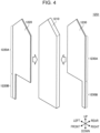
- FIG. 4 is an exploded perspective view of a heater body 1251 according to a first modification.
- the up-down direction, the front-rear direction, and the left-right direction are defined similarly to FIG. 2 and FIG. 3 .
- a direction in which the leading end of the heater body 1251 is inserted into the stick substrate 150 may also be referred to as "up direction”
- a direction opposite the up direction may also be referred to as "down direction”.
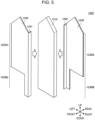
- FIG. 5 is an exploded perspective view of a heater body 1252 according to a second modification.
- the up-down direction, the front-rear direction, and the left-right direction are defined similarly to FIG. 2 and FIG. 3 .
- a direction in which the leading end of the heater body 1252 is inserted into the stick substrate 150 may also be referred to as "up direction”
- a direction opposite the up direction may also be referred to as "down direction”.
- a direction in which the first metal plate 1220, the resistive heat generator 1210, and the second metal plate 1230 are bonded together may also be referred to as "front-rear direction", and a direction orthogonal to the up-down direction and the front-rear direction may also be referred to as "left-right direction”.
- the first metal plate 1220 is provided with a first rib 1241
- the second metal plate 1230 is provided with a second rib 1242.
- the first rib 1241 is formed by bending one of the edges, in the lateral direction (i.e., the left-right direction) of the long shape of the first metal plate 1220, along the outer shape of the resistive heat generator 1210.
- the second rib 1242 is formed by bending the other one of the edges, in the lateral direction (i.e., the left-right direction) of the long shape of the second metal plate 1230, along the outer shape of the resistive heat generator 1210.
- the first metal plate 1220 and the second metal plate 1230 have increased strength in the front-rear direction in which the first rib 1241 and the second rib 1242 are bent, so that deformation in the front-rear direction can be suppressed. Accordingly, the heater body 1252 is less likely to deform in the normal direction to the principal surfaces of the first metal plate 1220 and the second metal plate 1230, so that the possibility of breakage of the heater 121 in the normal direction can be reduced.
- FIG. 6 is an exploded perspective view of a heater body 1253 according to a third modification.
- the up-down direction, the front-rear direction, and the left-right direction are defined similarly to FIG. 2 and FIG. 3 .
- a direction in which the leading end of the heater body 1253 is inserted into the stick substrate 150 may also be referred to as "up direction”
- a direction opposite the up direction may also be referred to as "down direction”.
- a direction in which the first metal plate 1220, the resistive heat generator 1210, and the second metal plate 1230 are bonded together may also be referred to as "front-rear direction", and a direction orthogonal to the up-down direction and the front-rear direction may also be referred to as "left-right direction”.
- the first metal plate 1220 is provided with the first rib 1241
- the second metal plate 1230 is provided with the second rib 1242.
- the surfaces of the first metal plate 1220 and the second metal plate 1230 facing each other in the thickness direction of the resistive heat generator 1210 are entirely cut out. Accordingly, the second regions 1220B and 1230B of the first metal plate 1220 and the second metal plate 1230 are only provided with the first rib 1241 and the second rib 1242.
- the surfaces of the first metal plate 1220 and the second metal plate 1230 in the second regions 1220B and 1230B may be entirely cut out without having any edges remaining.
- the resistive heat generator 1210 is supplied with electricity between the first rib 1241 and the second rib 1242.
- the distance between the first rib 1241 and the second rib 1242 becomes the width of the resistive heat generator 1210 in the left-right direction. Therefore, the electrical resistance value between the first rib 1241 and the second rib 1242 is higher than the electrical resistance value between the first metal plate 1220 and the second metal plate 1230 in the first regions 1220A and 1230a.
- the heater body 1253 according to the third modification can reduce the amount of heat generated by the resistive heat generator 1210 in the second regions 1220B and 1230B relative to the amount of heat generated by the resistive heat generator 1210 in the first regions 1220A and 1230A.
- the heater body 1253 according to the third modification is similar to the heater body 1250 illustrated in FIG. 2 and FIG. 3 in being able to enhance the heating efficiency of the stick substrate 150 and to reduce an effect that the heat produced from the heater 121 has on the reliability.
- FIG. 7 is an exploded perspective view of a heater body 1254 according to a fourth modification.
- the up-down direction, the front-rear direction, and the left-right direction are defined similarly to FIG. 2 and FIG. 3 .
- a direction in which the leading end of the heater body 1254 is inserted into the stick substrate 150 may also be referred to as "up direction”
- a direction opposite the up direction may also be referred to as "down direction”.
- the heater body 1254 according to the fourth modification is provided with the first rib 1241 and the second rib 1242 described in the second modification. Moreover, leading-end ribs 1243 are further provided in conformity with the angularly protruding shape toward the leading end (i.e., in the up direction) of the resistive heat generator 1210.
- leading-end ribs 1243 are formed by bending upper edges (located toward the leading end of the resistive heat generator 1210) of the first metal plate 1220 or the second metal plate 1230 along the outer shape of the resistive heat generator 1210.
- the leading-end ribs 1243 may be formed by bending two upper edges of the first metal plate 1220 or the second metal plate 1230 in conformity with the angularly protruding shape toward the leading end of the resistive heat generator 1210.
- the first metal plate 1220 and the second metal plate 1230 can cover the sword-tip-like pointy-shaped leading end (i.e., the upper end) of the resistive heat generator 1210. Accordingly, when the heater 121 is inserted into the stick substrate 150, the heater body 1254 can prevent delamination of the first metal plate 1220 and the second metal plate 1230 from the resistive heat generator 1210. Therefore, the heater body 1254 can further improve the durability of the heater 121 against insertion thereof into the stick substrate 150.
Landscapes
- Resistance Heating (AREA)
Abstract
Description
- The present invention relates to aerosol generation systems.
- Inhaler devices including electronic cigarettes and nebulizers that generate material to be inhaled by users are becoming widely popular. Such an inhaler device uses an aerosol source for generating an aerosol and a flavor source for imparting a flavor component to the generated aerosol, so as to be capable of generating a flavor-component-imparted aerosol. A user can taste the flavor by inhaling the flavor-component-imparted aerosol generated by the inhaler device.
- In recent years, technology related to an inhaler device of a type that uses a stick-shaped substrate as an aerosol source or a flavor source is being actively developed. For example, Patent Literature 1 indicated below discloses a blade-shaped heater that is inserted into the stick-shaped substrate to heat the substrate from the inside thereof.
- Patent Literature 1:
CN 209807157 U - However, with regard to the heater disclosed in Patent Literature 1 indicated above, since the entire heater produces heat uniformly, the heat produced from the heater may possibly be transmitted to areas other than the aerosol generating substrate. Therefore, the heating efficiency for the aerosol generating substrate may possibly decrease, and the heat produced from the heater may possibly have an effect on the reliability of the inhaler device.
- The present invention has been made in view of the above problem, and an object of the present invention is to provide a new and improved aerosol generation system that can suppress transmission of heat produced from the heater to areas other than the aerosol generating substrate.
- In order to solve the above problem, an aspect of the present invention provides an aerosol generation system including: a resistive heat generator that heats an aerosol generating substrate from an inside thereof; and a pair of metal plates provided at opposite surfaces of the resistive heat generator. The pair of metal plates each include a first region and a second region. The first region is where the metal plates face each other with the resistive heat generator interposed therebetween in a thickness direction of the resistive heat generator. The second region is where the metal plates do not face each other with the resistive heat generator interposed therebetween in the thickness direction of the resistive heat generator.
- The first regions may be provided toward a leading end of the resistive heat generator to be inserted into the aerosol generating substrate, and the second regions may be provided toward a trailing end opposite the leading end.
- The second regions may be provided as partial cut-outs of the metal plates such that the metal plates do not face each other with the resistive heat generator interposed therebetween in the thickness direction of the resistive heat generator
- The pair of metal plates in the second regions may be partially cut out such that edges of the metal plates remain, the edges being located diagonally from each other in a cross-sectional shape of the resistive heat generator.
- The metal plates cut out in the second regions may have a rectangular shape.
- A securing section having an insertion section into which the metal plates and the resistive heat generator are inserted may be further provided. The securing section secures the metal plates and the resistive heat generator to a housing.
- The metal plates in the second regions and the resistive heat generator may be inserted into the insertion section.
- The securing section may be composed of a super engineering plastic material.
- The securing section may have a circular or rectangular tabular shape.
- Each of the metal plates may be composed of a nickel-containing iron alloy.
- The resistive heat generator may have a tabular shape.
- A thickness of the tabular shape may be smaller than 1/4 of a width of the tabular shape.
- The aerosol generating substrate into which the resistive heat generator and the metal plates are inserted may be further provided.
- At least one of the metal plates may include a rib formed by bending an edge of the metal plate along an outer shape of the resistive heat generator from the opposite surfaces of the resistive heat generator
- The resistive heat generator may have an angularly protruding shape toward a leading end to be inserted into the aerosol generating substrate.
- At least one of the metal plates may further include a leading-end rib formed by bending an edge of the metal plate along the shape at the leading end of the resistive heat generator
- The resistive heat generator and the metal plates may be adhered together by using a conductive adhesive paste.
- The resistive heat generator may be a PTC heater.
- The resistive heat generator may contain barium titanate.
- A temperature of heat generated by the resistive heat generator may be below 350°C.
- According to the present invention described above, transmission of heat produced from the heater to areas other than the aerosol generating substrate can be suppressed.
-
- [
FIG. 1] FIG. 1 is a schematic diagram schematically illustrating a configuration example of an inhaler device according to an embodiment of the present invention. - [
FIG. 2] FIG. 2 is an exploded perspective view of a heater body included in the heater. - [
FIG. 3] FIG. 3 is a perspective view of the heater including the heater body illustrated inFIG. 2 . - [
FIG. 4] FIG. 4 is an exploded perspective view of a heater body according to a first modification. - [
FIG. 5] FIG. 5 is an exploded perspective view of a heater body according to a second modification. - [
FIG. 6] FIG. 6 is an exploded perspective view of a heater body according to a third modification. - [
FIG. 7] FIG. 7 is an exploded perspective view of a heater body according to a fourth modification. - A preferred embodiment of the present invention will be described in detail below with reference to the appended drawings. In this description and the drawings, structural elements having substantially identical functional configurations will be given the same reference signs, and redundant descriptions thereof will be omitted.
- An inhaler device according to a present configuration example generates an aerosol by heating a substrate containing an aerosol source from inside the substrate. The present configuration example will be described below with reference to
FIG. 1 . -
FIG. 1 is a schematic diagram schematically illustrating the configuration example of the inhaler device. As illustrated inFIG. 1 , aninhaler device 100 according to this configuration example includes apower supply 111, asensor 112, anotifier 113, amemory 114, acommunicator 115, acontroller 116, aheater 121, and acontainer 140. With regard to theinhaler device 100, inhalation is performed by a user in a state where astick substrate 150 is accommodated in thecontainer 140. The structural elements will be sequentially described below. - The
inhaler device 100 and thestick substrate 150 operate in cooperation with each other to generate the aerosol to be inhaled by the user. Therefore, the combination of theinhaler device 100 and thestick substrate 150 may be regarded as an aerosol generation system. - The
power supply 111 stores electric power. Thepower supply 111 supplies the electric power to the structural elements of theinhaler device 100. For example, thepower supply 111 may be a rechargeable battery, such as a lithium ion secondary battery. Thepower supply 111 may be recharged by being connected to an external power supply by, for example, a USB (universal serial bus) cable. Alternatively, thepower supply 111 may be recharged in a non-connected state with a power-transmitting device by wireless power transmission technology. As another alternative, thepower supply 111 may be removable from theinhaler device 100 so as to be replaceable with anew power supply 111. - The
sensor 112 detects various types of information regarding theinhaler device 100, and outputs the detected information to thecontroller 116. In an example, thesensor 112 may be a pressure sensor such as a microphone condenser, a flow sensor, or a temperature sensor. When detecting a numerical value generated in accordance with the user's inhalation, the pressure sensor, the flow sensor, or the temperature sensor can output information indicating that the inhalation has been performed by the user to thecontroller 116. In another example, thesensor 112 may be an input device, such as a button or a switch, receiving information input by the user. In particular, thesensor 112 may include a command button for starting/stopping aerosol generation. The input device that receives information input by the user can output the information input by the user to thecontroller 116. In another example, thesensor 112 may be a temperature sensor that detects the temperature of theheater 121. For example, by detecting the temperature of theheater 121 based on an electrical resistance value of theheater 121, the temperature sensor can determine the temperature of thestick substrate 150 accommodated in thecontainer 140. - The
notifier 113 notifies the user of information. In an example, thenotifier 113 is a light-emitting device, such as an LED (light-emitting diode). Accordingly, when thepower supply 111 needs to be recharged, when thepower supply 111 is being recharged, or when an abnormality has occurred in theinhaler device 100, thenotifier 113 can emit light in different patterns of light, respectively. Each pattern of light is a concept involving colors and on/off timings. Together with or in place of the light-emitting device, thenotifier 113 may be, for example, a display device that displays an image, a sound output device that outputs sound, and a vibration device that vibrates. Thenotifier 113 may also provide notification information indicating that inhalation by the user is possible. The notification information indicating that inhalation by the user is possible may be provided when the temperature of thestick substrate 150 heated by theheater 121 reaches a predetermined temperature. - The
memory 114 stores various types of information for operation of theinhaler device 100. Thememory 114 is, for example, a non-volatile storage medium, such as a flash memory. An example of the information stored in thememory 114 is information regarding the OS (operating system) of theinhaler device 100, such as the control information about the various types of structural elements controlled by thecontroller 116. Another example of the information stored in thememory 114 is information regarding inhalation by the user, such as the number of times of inhalation, the inhalation time, and the accumulated inhalation time period. - The
communicator 115 is a communication interface for exchanging information between theinhaler device 100 and another device. Thecommunicator 115 performs communication in conformity with any wired or wireless communication standard. Such a communication standard may be, for example, a wireless LAN (local area network), a wired LAN, Wi-Fi (registered trademark), or Bluetooth (registered trademark). In an example, thecommunicator 115 may transmit the information regarding the inhalation by the user to a smartphone to cause the smartphone to display the information regarding the inhalation by the user. In another example, thecommunicator 115 may receive information about a new OS from a server to update the information about the OS stored in thememory 114. - The
controller 116 functions as an arithmetic processing unit and a control device, and controls the overall operation in theinhaler device 100 in accordance with various programs. For example, thecontroller 116 is implemented by an electronic circuit, such as a CPU (central processing unit) or a microprocessor. Furthermore, thecontroller 116 may include a ROM (read only memory) that stores a program and arithmetic parameter to be used, and a RAM (random access memory) that temporarily stores an appropriately changing parameter. Theinhaler device 100 executes various processes based on control by thecontroller 116. Examples of the processes controlled by thecontroller 116 include supplying of electric power from thepower supply 111 to the other structural elements, recharging of thepower supply 111, detection of information by thesensor 112, notification of information by thenotifier 113, storing and reading of information by thememory 114, and exchanging of information by thecommunicator 115. Other processes executed by theinhaler device 100, such as an input of information to each structural element and a process based on information output from each structural element, are also controlled by thecontroller 116. - The
container 140 has aninternal space 141 and holds thestick substrate 150 while accommodating a portion of thestick substrate 150 within theinternal space 141. Thecontainer 140 has anopening 142 through which theinternal space 141 communicates with the outside, and holds thestick substrate 150 inserted in theinternal space 141 through theopening 142. For example, thecontainer 140 is a tubular body having theopening 142 and a bottom 143 as a bottom surface, and defines theinternal space 141 that is pillar-shaped. Thecontainer 140 has an inside diameter smaller than an outside diameter of thestick substrate 150 in at least a portion of the tubular body in the height direction, and may hold thestick substrate 150 while applying pressure around thestick substrate 150 inserted in theinternal space 141. Thecontainer 140 also has a function for defining a flow path for air traveling through thestick substrate 150. An air inlet serving as an inlet for the air entering the flow path is disposed in, for example, the bottom 143. On the other hand, an air outlet serving as an outlet for the air exiting from the flow path is theopening 142. - The
stick substrate 150 is a stick-shaped aerosol generating substrate. Thestick substrate 150 includes asubstrate 151 and aninhalation port 152. - The
substrate 151 contains an aerosol source. The aerosol source atomizes by being heated, so that an aerosol is generated. The aerosol source may include, for example, a material derived from tobacco, such as a product obtained by forming shredded tobacco or tobacco raw material into a granular form, a sheet form, or a powder form. The aerosol source may also include a material not derived from tobacco and made from a plant (such as mint or herb) other than tobacco. If theinhaler device 100 is a medical inhaler, the aerosol source may include a medicine to be inhaled by a patient. The aerosol source is not limited to a solid and may be a liquid, such as polyhydric alcohol, including glycerine or propylene glycol, or water. At least a portion of thesubstrate 151 is accommodated in theinternal space 141 of thecontainer 140 in the state where thestick substrate 150 is held by thecontainer 140. - The
inhalation port 152 is a member to be held in the user's mouth during inhalation. At least a portion of theinhalation port 152 protrudes from theopening 142 in the state where thestick substrate 150 is held by thecontainer 140. When the user holds theinhalation port 152 protruding from theopening 142 in the user's mouth and inhales, air flows into thecontainer 140 through the air inlet (not illustrated). The air flowing in travels through theinternal space 141 of thecontainer 140, that is, through thesubstrate 151, and reaches the inside of the user's mouth together with the aerosol generated from thesubstrate 151. - The
heater 121 heats the aerosol source so as to atomize the aerosol source and generate the aerosol. As will be described in detail later, theheater 121 is blade-shaped and is disposed to protrude from thebottom 143 of thecontainer 140 to theinternal space 141 of thecontainer 140. Therefore, when thestick substrate 150 is inserted into thecontainer 140, the blade-shapedheater 121 is inserted into thestick substrate 150 to pierce thesubstrate 151 of thestick substrate 150. When theheater 121 produces heat, the aerosol source contained in thestick substrate 150 atomizes by being heated from inside thestick substrate 150, whereby the aerosol is generated. Theheater 121 produces heat when supplied with electric power from thepower supply 111. In an example, when thesensor 112 detects that a predetermined user input has been performed, theheater 121 supplied with the electric power produces heat. When the temperature of thestick substrate 150 reaches the predetermined temperature, the aerosol is generated from thestick substrate 150. Accordingly, theinhaler device 100 allows for inhalation by the user. Subsequently, when thesensor 112 detects that a predetermined user input has been performed, the supply of electric power to theheater 121 may be stopped. In another example, in a time period in which thesensor 112 detects that the inhalation has been performed by the user, the aerosol may be generated by theheater 121 supplied with the electric power - Next, the
heater 121 included in theinhaler device 100 according to this embodiment will be described in further detail with reference toFIG. 2 andFIG. 3 .FIG. 2 is an exploded perspective view of aheater body 1250 included in theheater 121.FIG. 3 is a perspective view of theheater 121 including theheater body 1250 illustrated inFIG. 2 . - As illustrated in
FIG. 2 , theheater body 1250 includes aresistive heat generator 1210, afirst metal plate 1220, and asecond metal plate 1230. Theheater body 1250 can heat thestick substrate 150 from the inside thereof by using heat generated from theresistive heat generator 1210 supplied with electricity via thefirst metal plate 1220 and thesecond metal plate 1230. - As illustrated in
FIG. 3 , theheater body 1250 in which theresistive heat generator 1210, thefirst metal plate 1220, and thesecond metal plate 1230 are bonded together is secured to, for example, a housing of theinhaler device 100 by being held by asecuring section 1260. Specifically, for example, theheater 121 is constituted of theheater body 1250 and thesecuring section 1260. - In
FIG. 2 andFIG. 3 , a direction in which the leading end of theheater body 1250 is inserted into thestick substrate 150 may also be referred to as "up direction", and a direction opposite the up direction may also be referred to as "down direction". A direction in which thefirst metal plate 1220, theresistive heat generator 1210, and thesecond metal plate 1230 are bonded together may also be referred to as "front-rear direction", and a direction orthogonal to the up-down direction and the front-rear direction may also be referred to as "left-right direction". - The
resistive heat generator 1210 is a tabular member that generates heat by resistance heating. In detail, theresistive heat generator 1210 may be a PTC (positive temperature coefficient) heater that generates heat when electricity is supplied between thefirst metal plate 1220 and thesecond metal plate 1230. - A PTC heater uses a resistor having properties (PTC properties) in which an electrical resistance value increases significantly when the temperature reaches a predetermined temperature (referred to as "Curie temperature") such that an electric current does not flow therethrough. By utilizing the PTC properties, a PTC heater can control the amount of supplied electricity without having to use a control device, so as to be capable of controlling the heating temperature below the Curie temperature. Therefore, a PTC heater can heat a target below the Curie temperature. For example, the
resistive heat generator 1210 may be a PTC heater with barium titanate (BaTiO3) having the PTC properties as the resistor. In such a case, theresistive heat generator 1210 can set the Curie temperature of the barium titanate to 350°C, so as to be capable of heating thestick substrate 150 to a temperature below 350°C. - Each property, such as the Curie temperature of the barium titanate having the PTC properties or the electrical resistance value, can be controlled by using, for example, an additive added in a very small quantity to the barium titanate. In detail, for example, an alkaline-earth metal element, such as calcium (Ca) or strontium (Sr), or a rare-earth metal element, such as yttrium (Y), neodymium (Nd), samarium (Sm), or dysprosium (Dy), may be added to the barium titanate. The added element replaces the Ba site or the Ti site of the barium titanate, so that the structure of the sintered body of the barium titanate can be controlled. With the structure of the sintered body being controlled, each property, such as the Curie temperature or the electrical resistance value, of the barium titanate can be controlled.
- The
resistive heat generator 1210 may have a long tabular shape extending in the up-down direction. Specifically, the longitudinal direction of the long shape of theresistive heat generator 1210 corresponds to the up-down direction, whereas the lateral direction of the long shape corresponds to the left-right direction. By having a long tabular shape, theresistive heat generator 1210 has a rectangular cross-sectional shape that is orthogonal to the longitudinal direction (i.e., the up-down direction) of the long shape. Accordingly, as compared with a case where theresistive heat generator 1210 has a circular cross-sectional shape with the same surface area, the cross-sectional shape can have a longer perimeter. Therefore, theresistive heat generator 1210 can allow for a larger contact area between theheater 121 and thestick substrate 150 to which theheater 121 is to be inserted, whereby thestick substrate 150 can be heated more efficiently. For example, the tabular shape of theresistive heat generator 1210 may have a thickness smaller than 1/4 of the width of the long shape in the lateral direction (i.e., the left-right direction). - The
resistive heat generator 1210 at the leading end to be inserted into thestick substrate 150 may have an angularly protruding shape toward the leading end (i.e., in the up direction). The angular shape extending toward the leading end may have an acute angle, a right angle, or an obtuse angle. For example, theresistive heat generator 1210 may have a pentagonal tabular shape whose apex exists at the leading end (i.e., the upper end) to be inserted into thestick substrate 150 and that extends in the up-down direction. With regard to theresistive heat generator 1210, the leading end (i.e., the upper end) thereof to be inserted into thestick substrate 150 has a pointy shape like a sword tip, so that theheater 121 can be inserted into thestick substrate 150 more readily. - The
first metal plate 1220 and thesecond metal plate 1230 are a pair of electrode plates sandwiching theresistive heat generator 1210 therebetween. In detail, thefirst metal plate 1220 and thesecond metal plate 1230 may be provided at opposite principal surfaces opposing each other in the front-rear direction of the tabularresistive heat generator 1210. Thefirst metal plate 1220 and thesecond metal plate 1230 are provided apart from each other to prevent a short-circuit. - The
first metal plate 1220 and thesecond metal plate 1230 are bonded to theresistive heat generator 1210 by using a conductive adhesive paste, so that electricity can be supplied to theresistive heat generator 1210. An example of the conductive adhesive paste that can be used is a so-called anisotropic conductive adhesive having conductive particles uniformly distributed within an epoxy-based adhesive. - In an example, the
first metal plate 1220 and thesecond metal plate 1230 may be composed of metal with a low thermal expansion coefficient. For example, thefirst metal plate 1220 and thesecond metal plate 1230 may be composed of a nickel (Ni) containing iron alloy with a low thermal expansion coefficient, such as Invar (registered trademark). Accordingly, delamination of thefirst metal plate 1220 and thesecond metal plate 1230 from theresistive heat generator 1210 due to thermal expansion occurring when theresistive heat generator 1210 generates heat can be suppressed. - In the
inhaler device 100 according to this embodiment, thefirst metal plate 1220 includes afirst region 1220A and asecond region 1220B that are arranged in the longitudinal direction. Thesecond metal plate 1230 includes afirst region 1230A and asecond region 1230B that are arranged in the longitudinal direction. - The
first regions heater body 1250 to be inserted into thestick substrate 150, and thesecond regions - The
first regions first metal plate 1220 and thesecond metal plate 1230 face each other with theresistive heat generator 1210 interposed therebetween in the thickness direction of theresistive heat generator 1210. In thefirst regions first metal plate 1220 and thesecond metal plate 1230 may be provided to have the same rectangular shape and cover theresistive heat generator 1210. - In the
first regions first metal plate 1220 and thesecond metal plate 1230 may be substantially equal to the thickness of theresistive heat generator 1210 in the front-rear direction. Therefore, in thefirst regions first metal plate 1220 and thesecond metal plate 1230 is relatively short, so that the electrical resistance value between thefirst metal plate 1220 and thesecond metal plate 1230 is reduced, whereby a large amount of electric current flows therebetween. Accordingly, in thefirst regions resistive heat generator 1210 is relatively large. - The
second regions resistive heat generator 1210 interposed therebetween in the thickness direction of theresistive heat generator 1210. In detail, thesecond regions first metal plate 1220 and thesecond metal plate 1230 such as not to face each other with theresistive heat generator 1210 interposed therebetween in the thickness direction of theresistive heat generator 1210. - For example, the
first metal plate 1220 and thesecond metal plate 1230 in thesecond regions resistive heat generator 1210 in the thickness direction remain. For example, thefirst metal plate 1220 in thesecond region 1220B may have a rectangular region cut out therefrom such that a left edge thereof remains. Thesecond metal plate 1230 in thesecond region 1230B may have a rectangular region cut out therefrom such that a right edge thereof remains. - In the
second regions first metal plate 1220 and thesecond metal plate 1230 is substantially equal to the length of a diagonal line of the cross-sectional shape (i.e., the rectangular shape) of theresistive heat generator 1210. Therefore, in thesecond regions first metal plate 1220 and thesecond metal plate 1230 is relatively long, so that the electrical resistance value between thefirst metal plate 1220 and thesecond metal plate 1230 is increased, whereby electric current is less likely to flow therebetween. Accordingly, in thesecond regions resistive heat generator 1210 is relatively small. - Consequently, with regard to the
first metal plate 1220 and thesecond metal plate 1230, the amount of heat generated by theresistive heat generator 1210 can be adjusted by adjusting the distances between thefirst regions second regions first metal plate 1220 and thesecond metal plate 1230, the amount of heat generated by theresistive heat generator 1210 in thefirst regions resistive heat generator 1210 in thesecond regions heater body 1250 can heat thestick substrate 150 more efficiently. - The trailing ends of the
first metal plate 1220 and thesecond metal plate 1230 may each have a length equal to that of the trailing end of theresistive heat generator 1210. In such a case, as illustrated inFIG. 3 , thefirst metal plate 1220 and thesecond metal plate 1230 are bonded to theresistive heat generator 1210 at both thefirst regions second regions - As mentioned above, in the
second regions first metal plate 1220 and thesecond metal plate 1230 have cut-out regions that are diagonal from each other, so as not to face each other with theresistive heat generator 1210 interposed therebetween in the thickness direction of theresistive heat generator 1210. Therefore, in thesecond regions first metal plate 1220 and thesecond metal plate 1230 is increased, whereby the amount of heat generated from theresistive heat generator 1210 decreases. Hence, in thesecond regions resistive heat generator 1210 decreases. Consequently, theheater body 1250 is held by thesecuring section 1260 at thesecond regions first metal plate 1220 and thesecond metal plate 1230, thereby suppressing transmission of the heat to thesecuring section 1260. - The
securing section 1260 is a structural member that secures theheater body 1250 to the housing of theinhaler device 100. In detail, thesecuring section 1260 has a cylindrical or prismatic shape having aninsertion section 1261 with a slit-like recess structure or through-hole structure. - The
securing section 1260 may be composed of a super engineering plastic material. A super engineering plastic material has high heat resistance and high mechanical strength and can be formed into a desired shape inexpensively by injection molding, and is therefore suitable for use as a material for forming a structural member. For example, thesecuring section 1260 may be composed of PEEK (polyether ether ketone), which is a type of engineering plastic material. PEEK is thermoplastic resin having extremely high heat resistance and also having high dimensional stability. Therefore, with thesecuring section 1260 being composed of PEEK, a dimensional change caused by the heat generated by theresistive heat generator 1210 can be further reduced. - The
insertion section 1261 may be one recess or through-hole into which theheater body 1250 is to be inserted. Thefirst metal plate 1220 in thesecond region 1220B, thesecond metal plate 1230 in thesecond region 1230B, and theresistive heat generator 1210 may be inserted into theinsertion section 1261 of thesecuring section 1260. In addition to thefirst metal plate 1220 and thesecond metal plate 1230, theresistive heat generator 1210 is inserted into theinsertion section 1261 so that thesecuring section 1260 can hold theheater body 1250 more securely. - Since the amount of heat generated by the
resistive heat generator 1210 in thesecond regions securing section 1260 is reduced even when theresistive heat generator 1210 is held by thesecuring section 1260. Therefore, in theinhaler device 100 according to this embodiment, transmission of the heat generated by theresistive heat generator 1210 to areas other than thestick substrate 150 can be suppressed. Consequently, theinhaler device 100 according to this embodiment can enhance the heating efficiency of thestick substrate 150 and reduce an effect that the heat produced from theheater 121 has on the reliability. - First to fourth modifications of the
heater body 1250 according to this embodiment will now be described with reference toFIG. 4 to FIG. 7 . Since thefirst metal plate 1220 and thesecond metal plate 1230 are interchangeable, a description about thefirst metal plate 1220 can be interchangeably interpreted as a description about thesecond metal plate 1230. -
FIG. 4 is an exploded perspective view of aheater body 1251 according to a first modification. InFIG. 4 , the up-down direction, the front-rear direction, and the left-right direction are defined similarly toFIG. 2 andFIG. 3 . In detail, a direction in which the leading end of theheater body 1251 is inserted into thestick substrate 150 may also be referred to as "up direction", and a direction opposite the up direction may also be referred to as "down direction". A direction in which thefirst metal plate 1220, theresistive heat generator 1210, and thesecond metal plate 1230 are bonded together may also be referred to as "front-rear direction", and a direction orthogonal to the up-down direction and the front-rear direction may also be referred to as "left-right direction". - As illustrated in
FIG. 4 , in theheater body 1251 according to the first modification, thefirst regions first metal plate 1220 and thesecond metal plate 1230 may have a shape that corresponds to the shape of theresistive heat generator 1210. In detail, similar to theresistive heat generator 1210, thefirst regions first metal plate 1220 and thesecond metal plate 1230 may each have a pentagonal shape whose apex exists at the leading end to be inserted into thestick substrate 150. Accordingly, with regard to each of thefirst metal plate 1220 and thesecond metal plate 1230, the leading end thereof to be inserted into thestick substrate 150 has a pointy shape like a sword tip, so that theheater 121 can be inserted into thestick substrate 150 more readily. -
FIG. 5 is an exploded perspective view of aheater body 1252 according to a second modification. InFIG. 5 , the up-down direction, the front-rear direction, and the left-right direction are defined similarly toFIG. 2 andFIG. 3 . In detail, a direction in which the leading end of theheater body 1252 is inserted into thestick substrate 150 may also be referred to as "up direction", and a direction opposite the up direction may also be referred to as "down direction". A direction in which thefirst metal plate 1220, theresistive heat generator 1210, and thesecond metal plate 1230 are bonded together may also be referred to as "front-rear direction", and a direction orthogonal to the up-down direction and the front-rear direction may also be referred to as "left-right direction". - As illustrated in
FIG. 5 , in theheater body 1252 according to the second modification, thefirst metal plate 1220 is provided with afirst rib 1241, and thesecond metal plate 1230 is provided with asecond rib 1242. - In detail, the
first rib 1241 is formed by bending one of the edges, in the lateral direction (i.e., the left-right direction) of the long shape of thefirst metal plate 1220, along the outer shape of theresistive heat generator 1210. Thesecond rib 1242 is formed by bending the other one of the edges, in the lateral direction (i.e., the left-right direction) of the long shape of thesecond metal plate 1230, along the outer shape of theresistive heat generator 1210. - In an example, as illustrated in
FIG. 5 , thefirst rib 1241 may be formed by bending the right edge in thefirst region 1220A and thesecond region 1220B of thefirst metal plate 1220. Thesecond rib 1242 may be formed by bending the left edge in thefirst region 1230A and thesecond region 1230B of thesecond metal plate 1230. - In another example, although not illustrated, the
first rib 1241 may be formed by bending only the left edge in thefirst region 1220A of thefirst metal plate 1220. Thesecond rib 1242 may be formed by bending only the right edge in thefirst region 1230A of thesecond metal plate 1230. - With the
first rib 1241 and thesecond rib 1242 provided, thefirst metal plate 1220 and thesecond metal plate 1230 have increased strength in the front-rear direction in which thefirst rib 1241 and thesecond rib 1242 are bent, so that deformation in the front-rear direction can be suppressed. Accordingly, theheater body 1252 is less likely to deform in the normal direction to the principal surfaces of thefirst metal plate 1220 and thesecond metal plate 1230, so that the possibility of breakage of theheater 121 in the normal direction can be reduced. -
FIG. 6 is an exploded perspective view of aheater body 1253 according to a third modification. InFIG. 6 , the up-down direction, the front-rear direction, and the left-right direction are defined similarly toFIG. 2 andFIG. 3 . In detail, a direction in which the leading end of theheater body 1253 is inserted into thestick substrate 150 may also be referred to as "up direction", and a direction opposite the up direction may also be referred to as "down direction". A direction in which thefirst metal plate 1220, theresistive heat generator 1210, and thesecond metal plate 1230 are bonded together may also be referred to as "front-rear direction", and a direction orthogonal to the up-down direction and the front-rear direction may also be referred to as "left-right direction". - As illustrated in
FIG. 6 , in theheater body 1253 according to the third modification, thefirst metal plate 1220 is provided with thefirst rib 1241, and thesecond metal plate 1230 is provided with thesecond rib 1242. In thesecond regions first metal plate 1220 and thesecond metal plate 1230 facing each other in the thickness direction of theresistive heat generator 1210 are entirely cut out. Accordingly, thesecond regions first metal plate 1220 and thesecond metal plate 1230 are only provided with thefirst rib 1241 and thesecond rib 1242. - Specifically, in the
heater body 1253 according to the third modification, the surfaces of thefirst metal plate 1220 and thesecond metal plate 1230 in thesecond regions - Accordingly, the
resistive heat generator 1210 is supplied with electricity between thefirst rib 1241 and thesecond rib 1242. In such a case, the distance between thefirst rib 1241 and thesecond rib 1242 becomes the width of theresistive heat generator 1210 in the left-right direction. Therefore, the electrical resistance value between thefirst rib 1241 and thesecond rib 1242 is higher than the electrical resistance value between thefirst metal plate 1220 and thesecond metal plate 1230 in thefirst regions 1220A and 1230a. Hence, theheater body 1253 according to the third modification can reduce the amount of heat generated by theresistive heat generator 1210 in thesecond regions resistive heat generator 1210 in thefirst regions heater body 1253 according to the third modification is similar to theheater body 1250 illustrated inFIG. 2 andFIG. 3 in being able to enhance the heating efficiency of thestick substrate 150 and to reduce an effect that the heat produced from theheater 121 has on the reliability. -
FIG. 7 is an exploded perspective view of aheater body 1254 according to a fourth modification. InFIG. 7 , the up-down direction, the front-rear direction, and the left-right direction are defined similarly toFIG. 2 andFIG. 3 . In detail, a direction in which the leading end of theheater body 1254 is inserted into thestick substrate 150 may also be referred to as "up direction", and a direction opposite the up direction may also be referred to as "down direction". A direction in which thefirst metal plate 1220, theresistive heat generator 1210, and thesecond metal plate 1230 are bonded together may also be referred to as "front-rear direction", and a direction orthogonal to the up-down direction and the front-rear direction may also be referred to as "left-right direction". - As illustrated in
FIG. 7 , theheater body 1254 according to the fourth modification is provided with thefirst rib 1241 and thesecond rib 1242 described in the second modification. Moreover, leading-end ribs 1243 are further provided in conformity with the angularly protruding shape toward the leading end (i.e., in the up direction) of theresistive heat generator 1210. - In detail, the leading-
end ribs 1243 are formed by bending upper edges (located toward the leading end of the resistive heat generator 1210) of thefirst metal plate 1220 or thesecond metal plate 1230 along the outer shape of theresistive heat generator 1210. For example, the leading-end ribs 1243 may be formed by bending two upper edges of thefirst metal plate 1220 or thesecond metal plate 1230 in conformity with the angularly protruding shape toward the leading end of theresistive heat generator 1210. - With the leading-
end ribs 1243 provided, thefirst metal plate 1220 and thesecond metal plate 1230 can cover the sword-tip-like pointy-shaped leading end (i.e., the upper end) of theresistive heat generator 1210. Accordingly, when theheater 121 is inserted into thestick substrate 150, theheater body 1254 can prevent delamination of thefirst metal plate 1220 and thesecond metal plate 1230 from theresistive heat generator 1210. Therefore, theheater body 1254 can further improve the durability of theheater 121 against insertion thereof into thestick substrate 150. - Although a preferred embodiment of the present invention has been described in detail above with reference to the appended drawings, the present invention is not limited to this example. It is apparent to a person with a common knowledge of the technical field to which the present invention belongs that various modifications and alterations are conceivable within the scope of the technical ideas defined in the claims, and it is to be understood that such modifications and alterations naturally belong to the technical scope of the present invention.
- The following configurations also belong to the technical scope of the present invention.
- (1) An aerosol generation system comprising:
- a resistive heat generator that heats an aerosol generating substrate from an inside thereof; and
- a pair of metal plates provided at opposite surfaces of the resistive heat generator,
- wherein the pair of metal plates each include a first region and a second region, the first region being where the metal plates face each other with the resistive heat generator interposed therebetween in a thickness direction of the resistive heat generator, the second region being where the metal plates do not face each other with the resistive heat generator interposed therebetween in the thickness direction of the resistive heat generator.
- (2) The aerosol generation system according to (1), wherein the first regions are provided toward a leading end of the resistive heat generator to be inserted into the aerosol generating substrate, and the second regions are provided toward a trailing end opposite the leading end.
- (3) The aerosol generation system according to (1) or (2), wherein the second regions are provided as partial cut-outs of the metal plates such that the metal plates do not face each other with the resistive heat generator interposed therebetween in the thickness direction of the resistive heat generator
- (4) The aerosol generation system according to (3), wherein the pair of metal plates in the second regions are partially cut out such that edges of the metal plates remain, the edges being located diagonally from each other in a cross-sectional shape of the resistive heat generator
- (5) The aerosol generation system according to (4), wherein the metal plates cut out in the second regions have a rectangular shape.
- (6) The aerosol generation system according to any one of (1) to (5), further comprising a securing section having an insertion section into which the metal plates and the resistive heat generator are inserted, the securing section securing the metal plates and the resistive heat generator to a housing.
- (7) The aerosol generation system according to (6), wherein the metal plates in the second regions and the resistive heat generator are inserted into the insertion section.
- (8) The aerosol generation system according to (6) or (7), wherein the securing section is composed of a super engineering plastic material.
- (9) The aerosol generation system according to any one of (6) to (8), wherein the securing section has a circular or rectangular tabular shape.
- (10) The aerosol generation system according to (9), wherein each of the metal plates is composed of a nickel-containing iron alloy.
- (11) The aerosol generation system according to any one of (1) to (10), wherein the resistive heat generator has a tabular shape.
- (12) The aerosol generation system according to (11), wherein a thickness of the tabular shape is smaller than 1/4 of a width of the tabular shape.
- (13) The aerosol generation system according to any one of (1) to (12), further comprising the aerosol generating substrate into which the resistive heat generator and the metal plates are inserted.
- (14) The aerosol generation system according to any one of (1) to (13), wherein at least one of the metal plates includes a rib formed by bending an edge of the metal plate along an outer shape of the resistive heat generator from the opposite surfaces of the resistive heat generator
- (15) The aerosol generation system according to any one of (1) to (14), wherein the resistive heat generator has an angularly protruding shape toward a leading end to be inserted into the aerosol generating substrate.
- (16) The aerosol generation system according to (15), wherein at least one of the metal plates further includes a leading-end rib formed by bending an edge of the metal plate along the shape at the leading end of the resistive heat generator.
- (17) The aerosol generation system according to any one of (1) to (16), wherein the resistive heat generator and the metal plates are adhered together by using a conductive adhesive paste.
- (18) The aerosol generation system according to any one of (1) to (17), wherein the resistive heat generator is a PTC heater.
- (19) The aerosol generation system according to (18), wherein the resistive heat generator contains barium titanate.
- (20) The aerosol generation system according to any one of (1) to (19), wherein a temperature of heat generated by the resistive heat generator is below 350°C.
-
- 100
- inhaler device
- 121
- heater
- 140
- container
- 141
- internal space
- 142
- opening
- 143
- bottom
- 150
- stick substrate
- 151
- substrate
- 152
- inhalation port
- 1210
- resistive heat generator
- 1220
- first metal plate
- 1220A, 1230A
- first region
- 1220B, 1230B
- second region
- 1230
- second metal plate
- 1240
- rib
- 1241
- first rib
- 1242
- secondrib
- 1243
- leading-end rib
- 1250, 1251, 1252, 1253, 1254
- heater body
- 1260
- securing section
- 1261
- insertion section
Claims (20)
- An aerosol generation system comprising:a resistive heat generator that heats an aerosol generating substrate from an inside thereof; anda pair of metal plates provided at opposite surfaces of the resistive heat generator,wherein the pair of metal plates each include a first region and a second region, the first region being where the metal plates face each other with the resistive heat generator interposed therebetween in a thickness direction of the resistive heat generator, the second region being where the metal plates do not face each other with the resistive heat generator interposed therebetween in the thickness direction of the resistive heat generator.
- The aerosol generation system according to claim 1, wherein the first regions are provided toward a leading end of the resistive heat generator to be inserted into the aerosol generating substrate, and the second regions are provided toward a trailing end opposite the leading end.
- The aerosol generation system according to claim 1 or 2, wherein the second regions are provided as partial cut-outs of the metal plates such that the metal plates do not face each other with the resistive heat generator interposed therebetween in the thickness direction of the resistive heat generator.
- The aerosol generation system according to claim 3, wherein the pair of metal plates in the second regions are partially cut out such that edges of the metal plates remain, the edges being located diagonally from each other in a cross-sectional shape of the resistive heat generator.
- The aerosol generation system according to claim 4, wherein the metal plates cut out in the second regions have a rectangular shape.
- The aerosol generation system according to any one of claims 1 to 5, further comprising a securing section having an insertion section into which the metal plates and the resistive heat generator are inserted, the securing section securing the metal plates and the resistive heat generator to a housing.
- The aerosol generation system according to claim 6, wherein the metal plates in the second regions and the resistive heat generator are inserted into the insertion section.
- The aerosol generation system according to claim 6 or 7, wherein the securing section is composed of a super engineering plastic material.
- The aerosol generation system according to any one of claims 6 to 8, wherein the securing section has a circular or rectangular tabular shape.
- The aerosol generation system according to claim 9, wherein each of the metal plates is composed of a nickel-containing iron alloy.
- The aerosol generation system according to any one of claims 1 to 10, wherein the resistive heat generator has a tabular shape.
- The aerosol generation system according to claim 11, wherein a thickness of the tabular shape is smaller than 1/4 of a width of the tabular shape.
- The aerosol generation system according to any one of claims 1 to 12, further comprising the aerosol generating substrate into which the resistive heat generator and the metal plates are inserted.
- The aerosol generation system according to any one of claims 1 to 13, wherein at least one of the metal plates includes a rib formed by bending an edge of the metal plate along an outer shape of the resistive heat generator from the opposite surfaces of the resistive heat generator.
- The aerosol generation system according to any one of claims 1 to 14, wherein the resistive heat generator has an angularly protruding shape toward a leading end to be inserted into the aerosol generating substrate.
- The aerosol generation system according to claim 15, wherein at least one of the metal plates further includes a leading-end rib formed by bending an edge of the metal plate along the shape at the leading end of the resistive heat generator.
- The aerosol generation system according to any one of claims 1 to 16, wherein the resistive heat generator and the metal plates are adhered together by using a conductive adhesive paste.
- The aerosol generation system according to any one of claims 1 to 17, wherein the resistive heat generator is a PTC heater.
- The aerosol generation system according to claim 18, wherein the resistive heat generator contains barium titanate.
- The aerosol generation system according to any one of claims 1 to 19, wherein a temperature of heat generated by the resistive heat generator is below 350°C.
Applications Claiming Priority (1)
| Application Number | Priority Date | Filing Date | Title |
|---|---|---|---|
| PCT/JP2021/045027 WO2023105655A1 (en) | 2021-12-08 | 2021-12-08 | Aerosol generation system |
Publications (2)
| Publication Number | Publication Date |
|---|---|
| EP4445775A1 true EP4445775A1 (en) | 2024-10-16 |
| EP4445775A4 EP4445775A4 (en) | 2025-11-05 |
Family
ID=86729877
Family Applications (1)
| Application Number | Title | Priority Date | Filing Date |
|---|---|---|---|
| EP21967154.2A Pending EP4445775A4 (en) | 2021-12-08 | 2021-12-08 | AEROSOL GENERATION SYSTEM |
Country Status (6)
| Country | Link |
|---|---|
| US (1) | US20240260664A1 (en) |
| EP (1) | EP4445775A4 (en) |
| JP (1) | JP7746410B2 (en) |
| KR (1) | KR102966351B1 (en) |
| CN (1) | CN118201513A (en) |
| WO (1) | WO2023105655A1 (en) |
Family Cites Families (7)
| Publication number | Priority date | Publication date | Assignee | Title |
|---|---|---|---|---|
| JPH07118370B2 (en) * | 1987-04-22 | 1995-12-18 | 松下電器産業株式会社 | Method of manufacturing surface heating element |
| JP3092210B2 (en) * | 1991-06-25 | 2000-09-25 | 松下電器産業株式会社 | Positive resistance temperature coefficient heating element and method of manufacturing the same |
| EP3777578A4 (en) * | 2018-03-26 | 2021-07-28 | Japan Tobacco Inc. | AEROSOL GENERATION DEVICE, CONTROL PROCESS AND PROGRAM |
| EP3801087B1 (en) * | 2018-06-07 | 2023-11-01 | Philip Morris Products S.A. | Aerosol-generating device |
| CN209807157U (en) | 2019-04-12 | 2019-12-20 | 湖南中烟工业有限责任公司 | PTC heating element and low-temperature smoking set |
| CN212814273U (en) | 2020-04-26 | 2021-03-30 | 深圳麦克韦尔科技有限公司 | Heating assembly, atomizer and electronic atomization device |
| CN112137172A (en) | 2020-09-23 | 2020-12-29 | 深圳麦时科技有限公司 | Heating non-combustion baking device and heating device thereof |
-
2021
- 2021-12-08 EP EP21967154.2A patent/EP4445775A4/en active Pending
- 2021-12-08 CN CN202180104038.1A patent/CN118201513A/en active Pending
- 2021-12-08 KR KR1020247007433A patent/KR102966351B1/en active Active
- 2021-12-08 JP JP2023565755A patent/JP7746410B2/en active Active
- 2021-12-08 WO PCT/JP2021/045027 patent/WO2023105655A1/en not_active Ceased
-
2024
- 2024-04-19 US US18/639,966 patent/US20240260664A1/en active Pending
Also Published As
| Publication number | Publication date |
|---|---|
| EP4445775A4 (en) | 2025-11-05 |
| JP7746410B2 (en) | 2025-09-30 |
| WO2023105655A1 (en) | 2023-06-15 |
| KR102966351B1 (en) | 2026-05-18 |
| JPWO2023105655A1 (en) | 2023-06-15 |
| KR20240040115A (en) | 2024-03-27 |
| US20240260664A1 (en) | 2024-08-08 |
| CN118201513A (en) | 2024-06-14 |
Similar Documents
| Publication | Publication Date | Title |
|---|---|---|
| CN111436657B (en) | Power supply unit for aerosol inhaler | |
| CN111109688B (en) | Power supply unit of aerosol inhaler, control method thereof, and computer readable medium | |
| TWI730480B (en) | Power supply unit for aerosol inhaler, and control method and control program of the same | |
| JP2020195297A (en) | Control device for aerosol aspirator and aerosol aspirator | |
| US20240245142A1 (en) | Aerosol generation system | |
| US20240041120A1 (en) | Aerosol generation system | |
| US20240260664A1 (en) | Aerosol generation system | |
| US20240081409A1 (en) | Aerosol generation system | |
| US20240065329A1 (en) | Aerosol generation system | |
| US20240041119A1 (en) | Aerosol generation system | |
| US20240090575A1 (en) | Aerosol generation system | |
| WO2023275956A1 (en) | Aerosol generation system | |
| HK40026439A (en) | Power supply unit for aerosol inhaler, and control method and computer readable medium of the same | |
| HK40026439B (en) | Power supply unit for aerosol inhaler, and control method and computer readable medium of the same | |
| HK40026438A (en) | Power supply unit for aerosol inhaler, and control method and control program of the same |
Legal Events
| Date | Code | Title | Description |
|---|---|---|---|
| STAA | Information on the status of an ep patent application or granted ep patent |
Free format text: STATUS: THE INTERNATIONAL PUBLICATION HAS BEEN MADE |
|
| PUAI | Public reference made under article 153(3) epc to a published international application that has entered the european phase |
Free format text: ORIGINAL CODE: 0009012 |
|
| STAA | Information on the status of an ep patent application or granted ep patent |
Free format text: STATUS: REQUEST FOR EXAMINATION WAS MADE |
|
| 17P | Request for examination filed |
Effective date: 20240611 |
|
| AK | Designated contracting states |
Kind code of ref document: A1 Designated state(s): AL AT BE BG CH CY CZ DE DK EE ES FI FR GB GR HR HU IE IS IT LI LT LU LV MC MK MT NL NO PL PT RO RS SE SI SK SM TR |
|
| DAV | Request for validation of the european patent (deleted) | ||
| DAX | Request for extension of the european patent (deleted) | ||
| A4 | Supplementary search report drawn up and despatched |
Effective date: 20251002 |
|
| RIC1 | Information provided on ipc code assigned before grant |
Ipc: A24F 40/46 20200101AFI20250926BHEP |
|
| GRAP | Despatch of communication of intention to grant a patent |
Free format text: ORIGINAL CODE: EPIDOSNIGR1 |
|
| STAA | Information on the status of an ep patent application or granted ep patent |
Free format text: STATUS: GRANT OF PATENT IS INTENDED |