EP4445770A1 - Atomizer and electronic atomization device - Google Patents
Atomizer and electronic atomization device Download PDFInfo
- Publication number
- EP4445770A1 EP4445770A1 EP22925679.7A EP22925679A EP4445770A1 EP 4445770 A1 EP4445770 A1 EP 4445770A1 EP 22925679 A EP22925679 A EP 22925679A EP 4445770 A1 EP4445770 A1 EP 4445770A1
- Authority
- EP
- European Patent Office
- Prior art keywords
- heating cavity
- electrode
- heating
- cavity
- discharge ring
- Prior art date
- Legal status (The legal status is an assumption and is not a legal conclusion. Google has not performed a legal analysis and makes no representation as to the accuracy of the status listed.)
- Pending
Links
Images


Classifications
-
- A—HUMAN NECESSITIES
- A24—TOBACCO; CIGARS; CIGARETTES; SIMULATED SMOKING DEVICES; SMOKERS' REQUISITES
- A24F—SMOKERS' REQUISITES; MATCH BOXES; SIMULATED SMOKING DEVICES
- A24F40/00—Electrically operated smoking devices; Component parts thereof; Manufacture thereof; Maintenance or testing thereof; Charging means specially adapted therefor
- A24F40/40—Constructional details, e.g. connection of cartridges and battery parts
-
- A—HUMAN NECESSITIES
- A24—TOBACCO; CIGARS; CIGARETTES; SIMULATED SMOKING DEVICES; SMOKERS' REQUISITES
- A24F—SMOKERS' REQUISITES; MATCH BOXES; SIMULATED SMOKING DEVICES
- A24F40/00—Electrically operated smoking devices; Component parts thereof; Manufacture thereof; Maintenance or testing thereof; Charging means specially adapted therefor
- A24F40/10—Devices using liquid inhalable precursors
-
- A—HUMAN NECESSITIES
- A24—TOBACCO; CIGARS; CIGARETTES; SIMULATED SMOKING DEVICES; SMOKERS' REQUISITES
- A24F—SMOKERS' REQUISITES; MATCH BOXES; SIMULATED SMOKING DEVICES
- A24F40/00—Electrically operated smoking devices; Component parts thereof; Manufacture thereof; Maintenance or testing thereof; Charging means specially adapted therefor
- A24F40/40—Constructional details, e.g. connection of cartridges and battery parts
- A24F40/46—Shape or structure of electric heating means
-
- A—HUMAN NECESSITIES
- A24—TOBACCO; CIGARS; CIGARETTES; SIMULATED SMOKING DEVICES; SMOKERS' REQUISITES
- A24F—SMOKERS' REQUISITES; MATCH BOXES; SIMULATED SMOKING DEVICES
- A24F40/00—Electrically operated smoking devices; Component parts thereof; Manufacture thereof; Maintenance or testing thereof; Charging means specially adapted therefor
- A24F40/40—Constructional details, e.g. connection of cartridges and battery parts
- A24F40/46—Shape or structure of electric heating means
- A24F40/465—Shape or structure of electric heating means specially adapted for induction heating
-
- H—ELECTRICITY
- H05—ELECTRIC TECHNIQUES NOT OTHERWISE PROVIDED FOR
- H05B—ELECTRIC HEATING; ELECTRIC LIGHT SOURCES NOT OTHERWISE PROVIDED FOR; CIRCUIT ARRANGEMENTS FOR ELECTRIC LIGHT SOURCES, IN GENERAL
- H05B7/00—Heating by electric discharge
- H05B7/18—Heating by arc discharge
Definitions
- the present application relates to the field of atomization technology, and in particular to an atomizer and an electronic atomization device.
- Aerosol is a colloidal dispersion formed by small solid or liquid masses dispersed and suspended in a gaseous medium. Since the aerosol can be absorbed by the human body through the respiratory system, it provides users with a new alternative absorption method, such as an electronic atomization device that can heat an aerosol generating substrate of herbs or creams to generate aerosol, which is used in different fields to deliver inhalable aerosols to users, thus replacing conventional product forms and absorption methods. Electronic atomization devices usually use resistive or electromagnetic induction to heat the aerosol-generating substrate.
- resistive heating uses an external power supply to energize a resistive member to generate heat, and then the heated resistance member transfers the heat to the aerosol-generating substrate through heat conduction.
- the heat conduction takes time and has a lag, so that the aerosol-generating substrate adjacent to the resistance member is often overburned or even scorched, and overburning or scorching at high temperature results in poor taste consistency.
- metal substances in the resistance heating member may enter an aerosol formed by atomization of the aerosol-generating substrate, thereby affecting the atomization taste.
- a first aspect of the present application provides an atomizer.
- the atomizer includes: a heating member forming a heating cavity and an accommodating cavity in heat conduction with the heating cavity; an electrode assembly including a first electrode and a second electrode hat at least partially extending into the heating cavity; and a magnetic member provided outside the heating member and configured to apply a magnetic field to the heating cavity.
- a magnetic rotating electric arc rotating around an axis of the heating cavity is controllably formed between the first electrode and the second electrode in the heating cavity.
- both the first electrode and the second electrode at least partially extend into the heating cavity, and after a high voltage is applied to the first electrode and the second electrode, an electric arc can be formed between the first electrode and the second electrode by breakdown in the heating cavity.
- the magnetic member applies the magnetic field to the heating cavity, and an electric field force is applied to the electric arc to rotate the electric arc around the axis of the heating cavity, thereby forming the magnetic rotating electric arc.
- the rotating electric arc exists in the whole heating cavity, thus forming an electric arc surface surrounding the heating cavity, which can heat the heating cavity as a whole and form a uniform temperature field, so as to utilize plasma to efficiently and uniformly heat and atomize the aerosol-generating substrate, thereby improving the atomization taste.
- the magnetic member includes a magnetic ring sleeved on the heating member, and an orthographic projection of the magnetic ring onto an axial cross-section of the heating cavity covers an orthographic projection of the heating cavity onto the same axial cross-section of the heating cavity.
- the first electrode includes a discharge ring located in the heating cavity, the discharge ring extends along an outer circumferential direction of the heating cavity, and a discharge end of the second electrode in the heating cavity is located on a central axis of the discharge ring.
- the discharge end of the second electrode is constructed as a cylindrical shape or a ring shape.
- the heating cavity is located at a bottom portion of the accommodating cavity in an axial direction thereof, and the discharge end of the second electrode is coplanar with a center point of the discharge ring, or the discharge end of the second electrode is lowered by a preset distance with respect to the center point of the discharge ring in a direction away from the accommodating cavity.
- the heating member includes a tube body, a partition plate, and a bottom plate, the partition plate and the bottom plate are spaced apart in the tube body along an axial direction thereof, the heating cavity is defined among the partition plate, the tube body, and the bottom plate, and the accommodating cavity is defined between a surface of the partition plate away from the bottom plate and the tube body.
- the heating cavity includes a first heating cavity and a second heating cavity that are in communication with each other, the first heating cavity surrounds an outer peripheral side of the accommodating cavity in a radial direction thereof, and the second heating cavity is located at a bottom portion of the accommodating cavity in an axial direction thereof.
- the discharge ring is located in the first heating cavity and surrounds an outer periphery of the accommodating cavity, and the discharge end of the second electrode is located in the second heating cavity and has a height difference with a center point of the discharge ring.
- the first electrode further includes an electrical connection section connected to the discharge ring and at least partially located in the heating cavity.
- a distance between the electrical connection section and the second electrode along a radial direction of the heating cavity is greater than a radial distance between the discharge ring and the second electrode.
- the electrical connection section is relatively insulated from the second electrode.
- the heating cavity includes a third heating cavity surrounding an outer peripheral side of the accommodating cavity in a radial direction thereof.
- the first electrode includes a first discharge ring
- the second electrode includes a second discharge ring
- the first discharge ring and the second discharge ring are both located in the third heating cavity and are both spaced axially around an outer periphery of the accommodating cavity.
- the heating member is made of an infrared radiation material.
- a bottom wall of the accommodating cavity faces the heating cavity and is coated with an infrared radiation coating.
- a second aspect of the present application provides an electronic atomization device.
- the electronic atomization device includes the aforementioned atomizer in the first aspect.
- first and second are only used for descriptive purposes and cannot be understood as indicating or implying relative importance or implicitly indicating the number of indicated technical features.
- the features defined with “first” and “second” may explicitly or implicitly include at least one of the features.
- a plurality of' means at least two, such as two, three, etc., unless otherwise expressly and specifically defined.
- the terms “mount”, “connect”, “contact”, “fix” and other terms should be understood in a broad sense, for example, they can be fixed connections, detachable connections, or integrated. They can be mechanical connection or electrical connection. They can be directly connected or indirectly connected through an intermediate medium. They can be the connection within two elements or the interaction relationship between two elements, unless otherwise expressly limited. For those skilled in the art, the specific meaning of the above terms in the present application can be understood according to the specific situation.
- the first feature "above” or “below” the second feature may be in direct contact with the first and second features, or the first and second features may be in indirect contact through an intermediate medium.
- the first feature is “above” the second feature, but the first feature is directly above or diagonally above the second feature, or it only means that the horizontal height of the first feature is higher than the second feature.
- the first feature is "below” of the second feature, which can mean that the first feature is directly below or obliquely below the second feature, or simply that the horizontal height of the first feature is less than that of the second feature.
- an atomizer 100 heats and atomizes an aerosol-generating substrate through plasma generated by a magnetic rotating electric arc.
- the high energy density of plasma heating is utilized to achieve instant rapid heating atomization, the preheating time is effectively shortened, the scorching caused by too long preheating time is prevented, and the atomization taste is improved.
- the plasma generated by the magnetic rotating electric arc is more uniform, and a more uniform temperature field can be formed, so as to uniformly heat and atomize the aerosol-generating substrate, thereby further improving the atomization taste.
- the atomizer 100 includes a heating member 10, an electrode assembly 30, and a magnetic member 50.
- the heating member 10 forms a heating cavity 11 and an accommodating cavity 13 in heat conduction with the heating cavity 11, and the accommodating cavity 13 is configured to receive an aerosol-generating substrate.
- the electrode assembly 30 includes a first electrode 32 and a second electrode 34 both at least partially extending into the heating cavity 11.
- the magnetic member 50 is provided outside the heating member 10 and configured to apply a magnetic field to the heating cavity 11. By an action of the magnetic field, a magnetic rotating electric arc rotating around an axis of the heating cavity 11 can be controllably formed between the first electrode 32 and the second electrode 34 within the heating cavity 11.
- Both the first electrode 32 and the second electrode 34 at least partially extend into the heating cavity 11, and after a high voltage is applied to the first electrode 32 and the second electrode 34, an electric arc can be formed between the first electrode 32 and the second electrode 34 by breakdown in the heating cavity 11.
- the magnetic member 50 applies the magnetic field to the heating cavity 11, and an electric field force is applied to the electric arc to rotate the electric arc around the axis of the heating cavity 11, thereby forming the magnetic rotating electric arc.
- the rotating electric arc exists in the whole heating cavity 11, thus forming an electric arc surface surrounding the heating cavity 11, which can heat the heating cavity 11 as a whole and form a uniform temperature field, so as to utilize plasma to efficiently and uniformly heat and atomize the aerosol-generating substrate, thereby improving the atomization taste.
- the magnetic member 50 includes a magnetic ring sleeved on the heating member 10.
- An orthographic projection of the magnetic ring onto an axial cross-section of the heating cavity 11 covers an orthographic projection of the heating cavity 11 onto the same axial cross-section of the heating cavity 11. That is, the magnetic ring covers at least an outer periphery of the heating cavity 11, so as to apply the electric field force perpendicular to the electric arc into the heating cavity 11, so that the electric arc rotates about the axis of the heating cavity 11 under the action of the electric field force.
- the magnetic ring is provided coaxially with the heating cavity 11 to form the magnetic rotating electric arc rotating around the axis of the heating cavity 11 in the heating cavity 11, so that the temperature field in the heating cavity 11 is uniform, thereby uniformly heating the aerosol-generating substrate in the accommodating cavity 13.
- the heating cavity 11 and the accommodating cavity 13 are also provided coaxially, so that the temperature field in the heating cavity 11 uniformly acts on the aerosol-generating substrate in the accommodating cavity 13.
- the magnetic member 50 may be configured to include a plurality of sub-magnets or the like arranged along a circumferential direction of the heating member 10.
- the specific structure of the magnetic member 50 is not limited herein, as long as the magnetic force perpendicular to the electric arc can be applied into the heating cavity 11.
- the first electrode 32 includes a discharge ring 321 located in the heating cavity 11, and the discharge ring 321 extends along an outer circumferential direction of the heating cavity 11.
- a discharge end of the second electrode 34 located in the heating cavity 11 is located on a central axis of the discharge ring 321.
- the discharge ring 321 is provided in the heating cavity 11, and an extension direction of the discharge ring 321 is parallel to the outer circumferential direction of the heating cavity 11, which is equivalent to that the discharge ring 321 is provided coaxially with the heating cavity 11.
- the discharge end of the second electrode 34 is provided on the central axis of the discharge ring 321, as such, after the electric arc is formed between the discharge end of the second electrode 34 and the discharge ring 321, the electric arc rotates circumferentially along the extension of the discharge ring 321 under the action of the magnetic field to form the magnetic rotating electric arc, thereby uniformly heating and atomizing the aerosol-generating substrate.
- the discharge end of the second electrode 34 is constructed as a cylindrical shape or a ring shape, that is, the discharge end of the second electrode 34 may be a cylindrical member or a ring-shaped member with a small diameter. Both the cylindrical member and the ring-shaped member are capable of performing breakdown discharge with the discharge ring 321 in the first electrode 32.
- a discharge distance is preferably in a range of 2 mm to 8 mm.
- the first electrode 32 and the second electrode 34 of the electrode assembly 30 are both made of any one of tungsten alloy, carbon fiber, copper alloy, and graphite or any combination thereof. Diameters of the first electrode 32 and the second electrode 34 are both in a range of 0.4 mm to 1.5 mm. Optionally, a radius of the discharge ring 321 is in the range of 3 mm to 6 mm. In some embodiments, the heating cavity 11 is filled with an inert gas.
- the inert gas filled in the heating cavity 11 can be ionized to form plasma and generate heat, and the generated heat can be efficiently transferred to the accommodating cavity 13 through the inert gas, thereby improving the heat transfer efficiency.
- the heating cavity 11 is filled with a gas such as helium, neon, or argon. It should be understood that in some other embodiments, the heating cavity 11 may be filled with air, which is not limited herein.
- an air pressure inside the heating cavity 11 is less than a standard atmospheric pressure, so that a pressure inside the heating cavity 11 is kept at a relatively low level, and a cavity wall (i.e., the heating member 10) of the heating cavity 11 will not be subject to excessive pressure, a wall thickness and strength of the heating member 10 can be reduced, and the heat transfer efficiency can be further improved.
- the air pressure inside the heating cavity 11 is between 1/5 of atmospheric pressure and one atmospheric pressure.
- the air pressure in the heating cavity 11 is 1/5 to 1/3 of the atmospheric pressure.
- the air pressure inside the heating cavity 11 may also be configured to be the standard atmospheric pressure, which is not limited herein.
- the heating member 10 is made of an infrared radiation material. After the heat generated in the heating cavity 11 is transferred to the heating member 10, the heating member 10 can form infrared rays radiating to the accommodating cavity 13. In this way, not only the plasma generated by the electric arc can be used to heat and atomize the aerosol-generating substrate, but also the aerosol-generating substrate can be heated and atomized by infrared radiation, thereby further improving the heating effect.
- the heating member 10 is made of any one of transparent quartz glass, opal quartz, black silica quartz, silicon nitride, zirconium oxide, and aluminum oxide or any combination thereof, which can generate infrared radiation after being heated, so as to perform infrared radiation heating on the aerosol-generating substrate through the heating member 10.
- a bottom wall of the accommodating cavity 13 faces the heating cavity 11 and is coated with an infrared radiation coating, so that more intensive infrared radiation heating can be achieved.
- the infrared radiation coating made of one or more of oxide of iron, manganese and copper, CrC, TiCN, diamond-like carbon (DLC), HBQ black silicon, cordierite, transition metal oxide series spinel, rare earth oxide, ion co-doped perovskite, silicon carbide, zircon, and boron nitride.
- the heating cavity 11 is located at a bottom portion of the accommodating cavity 13 in an axial direction thereof.
- the discharge end of the second electrode 34 is coplanar with a center point of the discharge ring 321, so as to form an electric arc extending along the radial direction of the discharge ring 321.
- the electric arc rotates under the action of the magnetic field to form an electric arc surface covering an interior of the discharge ring 321, so as to uniformly heat the bottom portion of the accommodating cavity 13, and uniformly heat and atomize the aerosol-generating substrate in the accommodating cavity 13.
- the discharge end of the second electrode 34 is lowered by a preset distance with respect to the center point of the discharge ring 321 in a direction away from the accommodating cavity 13, so that the electric arc forms a conical arc surface under the action of the magnetic field force, which is conducive to focusing the energy upward and further improves the uniformity of the temperature field in the heating cavity 11.
- the preset distance by which the second electrode 34 is lowered is in a range of 0 mm to 1.0 mmm.
- the heating member 10 includes a tube body 14, a partition plate 15, and a bottom plate 16.
- the partition plate 15 and the bottom plate 16 are spaced apart in the tube body 14 along an axial direction of the tube body 14.
- the heating cavity 11 is defined among the partition plate 15, the tube body 14, and the bottom plate 16, and the accommodating cavity 13 is defined between a surface of the partition plate 15 away from the bottom plate 16 and the tube body 14.
- the accommodating cavity 13 and the heating cavity 11 arranged along the axial direction of the tube body 14 are formed in the tube body 14, and the aerosol-generating substrate in the accommodating cavity 13 at the top is heated by the heat generated in the heating cavity 11.
- a thickness of the partition plate 15 is in a range of 0.5 mm to 1.0 mm, which can satisfy the strength requirement and also can conduct heat efficiently.
- the partition plate 15 and the tube body 14 may be integrally formed, and the bottom plate 16 may be fixed in the tube body 14 through a melting process after the electrode assembly 30 is assembled.
- the bottom plate 16 is made of a heat-resistant material. The material of the bottom plate 16 may be the same as or different from that of the tube body 14 and the partition plate 15, which is not limited herein.
- the heating cavity 11 includes a first heating cavity 112 and a second heating cavity 114 that are in communication with each other.
- the first heating cavity 112 surrounds an outer peripheral side of the accommodating cavity 13 in the radial direction thereof, and the second heating cavity 114 is located at the bottom portion of the accommodating cavity 13 in the axial direction thereof.
- the discharge ring 321 is located in the first heating cavity 112 and surrounds an outer periphery of the accommodating cavity 13.
- the discharge end of the second electrode 34 is located in the second heating cavity 114 and has a height difference with the center point of the discharge ring 321.
- the heating cavity 11 entirely surrounds the heating cavity 11 to perform heating and atomization from an outer periphery of the aerosol-generating substrate.
- an electric arc passing through the first heating cavity 112 and the second heating cavity 114 can be formed between the discharge ring 321 and the discharge end of the second electrode 34.
- the electric arc rotates around the axis of the heating cavity 11 under the action of the magnetic field force, and uniform temperature fields can be formed in both the first heating cavity 112 and the second heating cavity 114, so as to uniformly heat a side surface and a bottom surface of the aerosol-generating substrate, thereby improving the atomization taste.
- the first electrode 32 further includes an electrical connection section 323 connected to the discharge ring 321 and at least partially located in the heating cavity 11.
- a distance between the electrical connection section 323 and the second electrode 34 along a radial direction of the heating cavity 11 is greater than a radial distance between the discharge ring 321 and the second electrode 34.
- a radial distance between the electrical connection section 323 and the second electrode 34 is greater than the radial distance between the discharge ring 321 and the second electrode 34, so as to ensure that the discharge breakdown occurs between the discharge ring 321 and the second electrode 34 with a small distance, and ensure the reliability of an ionization breakdown position.
- the electrical connection section 323 is relatively insulated from the second electrode 34, which may further prevent ionization breakdown between the electrical connection section 323 and the second electrode 34.
- a heat-resistant insulating sleeve is sleeved on the electrical connection section 323, and the heat-resistant insulating sleeve may be a ceramic tube, a quartz tube, or a high dielectric insulating film layer, so as to effectively insulate the electrical connection end 323 from the second electrode 34.
- the requirement for a power supply for supplying power to the atomizer 100 is that a current provided by the power supply always flows from one of the first electrode 32 and the second electrode 34 to the other one of the first electrode 32 and the second electrode 34 without voltage commutation.
- the current is directed from the second electrode 34 to the first electrode 32 to reduce ablation loss of the second electrode 34 at the center.
- the heating cavity 11 includes a third heating cavity surrounding the outer peripheral side of the accommodating cavity 13 in the radial direction thereof.
- the first electrode 32 and the second electrode 34 include a first discharge ring and a second discharge ring, respectively, both of which are located in the third heating cavity and are spaced axially around the outer periphery of the accommodating cavity 13. In this way, the heating cavity 11 entirely surrounds the heating cavity 11 to perform heating and atomization from an outer periphery of the aerosol-generating substrate.
- an electric arc can be formed between the first discharge ring and the second discharge ring in the first heating cavity 112.
- the electric arc rotates along circumferential directions of the first discharge ring and the second discharge ring under the action of the magnetic field force, that is, rotates around the axis of the heating cavity 11.
- a uniform temperature field can be formed in the first heating cavity 112, so as to uniformly heat a side surface of the aerosol-generating substrate, thereby improving the atomization taste.
- an electronic atomization device includes the aforementioned atomizer 100.
- the atomizer 100 includes the heating member 10, the electrode assembly 30, and the magnetic member 50.
- the heating member 10 is formed with the heating cavity 11 and the accommodating cavity 13 in heat conduction with the heating cavity 11, and the accommodating cavity 13 is configured to receive an aerosol-generating substrate.
- the electrode assembly 30 includes the first electrode 32 and the second electrode 34 both at least partially extending into the heating cavity 11.
- the magnetic member 50 is provided outside the heating member 10 and configured to apply a magnetic field to the heating cavity 11. By the action of the magnetic field, a magnetic rotating electric arc rotating around an axis of the heating cavity 11 can be controllably formed between the first electrode 32 and the second electrode 34 within the heating cavity 11.
- Both the first electrode 32 and the second electrode 34 at least partially extend into the heating cavity 11, and after a high voltage is applied to the first electrode 32 and the second electrode 34, an electric arc can be formed between the first electrode 32 and the second electrode 34 by breakdown in the heating cavity 11.
- the magnetic member 50 applies the magnetic field to the heating cavity 11, and an electric field force is applied to the electric arc to rotate the electric arc around the axis of the heating cavity 11, thereby forming the magnetic rotating electric arc.
- the rotating electric arc exists in the whole heating cavity 11, thus forming an electric arc surface surrounding the heating cavity 11, which can heat the heating cavity 11 as a whole and form a uniform temperature field, so as to utilize plasma to efficiently and uniformly heat and atomize the aerosol-generating substrate, thereby improving the atomization taste.
Landscapes
- Physics & Mathematics (AREA)
- Engineering & Computer Science (AREA)
- Plasma & Fusion (AREA)
- Plasma Technology (AREA)
- Electrostatic Spraying Apparatus (AREA)
Abstract
Description
- This application claims priority of
Chinese Patent Application No. 2022202663729, filed on February 9, 2022 - The present application relates to the field of atomization technology, and in particular to an atomizer and an electronic atomization device.
- Aerosol is a colloidal dispersion formed by small solid or liquid masses dispersed and suspended in a gaseous medium. Since the aerosol can be absorbed by the human body through the respiratory system, it provides users with a new alternative absorption method, such as an electronic atomization device that can heat an aerosol generating substrate of herbs or creams to generate aerosol, which is used in different fields to deliver inhalable aerosols to users, thus replacing conventional product forms and absorption methods. Electronic atomization devices usually use resistive or electromagnetic induction to heat the aerosol-generating substrate.
- In the conventional technology, whether using resistive or electromagnetic induction to heat aerosol-generating substrate, a preheating waiting time is long, which is not convenient for users. In addition, resistive heating uses an external power supply to energize a resistive member to generate heat, and then the heated resistance member transfers the heat to the aerosol-generating substrate through heat conduction. The heat conduction takes time and has a lag, so that the aerosol-generating substrate adjacent to the resistance member is often overburned or even scorched, and overburning or scorching at high temperature results in poor taste consistency. Moreover, when a resistance heating member is in contact with and heats the aerosol-generating substrate, metal substances in the resistance heating member may enter an aerosol formed by atomization of the aerosol-generating substrate, thereby affecting the atomization taste.
- Accordingly, it is necessary to provide an atomizer and an electronic atomization device to address a problem of poor atomization taste of the conventional electronic atomization devices.
- A first aspect of the present application provides an atomizer. The atomizer includes: a heating member forming a heating cavity and an accommodating cavity in heat conduction with the heating cavity; an electrode assembly including a first electrode and a second electrode hat at least partially extending into the heating cavity; and a magnetic member provided outside the heating member and configured to apply a magnetic field to the heating cavity. By an action of the magnetic field, a magnetic rotating electric arc rotating around an axis of the heating cavity is controllably formed between the first electrode and the second electrode in the heating cavity.
- According to the aforementioned atomizer, both the first electrode and the second electrode at least partially extend into the heating cavity, and after a high voltage is applied to the first electrode and the second electrode, an electric arc can be formed between the first electrode and the second electrode by breakdown in the heating cavity. At the same time, the magnetic member applies the magnetic field to the heating cavity, and an electric field force is applied to the electric arc to rotate the electric arc around the axis of the heating cavity, thereby forming the magnetic rotating electric arc. In this way, instead of forming an electric arc at a certain position of the heating cavity to generate plasma heating, the rotating electric arc exists in the whole heating cavity, thus forming an electric arc surface surrounding the heating cavity, which can heat the heating cavity as a whole and form a uniform temperature field, so as to utilize plasma to efficiently and uniformly heat and atomize the aerosol-generating substrate, thereby improving the atomization taste.
- In the first aspect of the present application, the magnetic member includes a magnetic ring sleeved on the heating member, and an orthographic projection of the magnetic ring onto an axial cross-section of the heating cavity covers an orthographic projection of the heating cavity onto the same axial cross-section of the heating cavity.
- In the first aspect of the present application, the first electrode includes a discharge ring located in the heating cavity, the discharge ring extends along an outer circumferential direction of the heating cavity, and a discharge end of the second electrode in the heating cavity is located on a central axis of the discharge ring.
- In the first aspect of the present application, the discharge end of the second electrode is constructed as a cylindrical shape or a ring shape.
- In the first aspect of the present application, the heating cavity is located at a bottom portion of the accommodating cavity in an axial direction thereof, and the discharge end of the second electrode is coplanar with a center point of the discharge ring, or the discharge end of the second electrode is lowered by a preset distance with respect to the center point of the discharge ring in a direction away from the accommodating cavity.
- In the first aspect of the present application, the heating member includes a tube body, a partition plate, and a bottom plate, the partition plate and the bottom plate are spaced apart in the tube body along an axial direction thereof, the heating cavity is defined among the partition plate, the tube body, and the bottom plate, and the accommodating cavity is defined between a surface of the partition plate away from the bottom plate and the tube body.
- In the first aspect of the present application, the heating cavity includes a first heating cavity and a second heating cavity that are in communication with each other, the first heating cavity surrounds an outer peripheral side of the accommodating cavity in a radial direction thereof, and the second heating cavity is located at a bottom portion of the accommodating cavity in an axial direction thereof. The discharge ring is located in the first heating cavity and surrounds an outer periphery of the accommodating cavity, and the discharge end of the second electrode is located in the second heating cavity and has a height difference with a center point of the discharge ring.
- In the first aspect of the present application, the first electrode further includes an electrical connection section connected to the discharge ring and at least partially located in the heating cavity. In the heating cavity, a distance between the electrical connection section and the second electrode along a radial direction of the heating cavity is greater than a radial distance between the discharge ring and the second electrode.
- In the first aspect of the present application, the electrical connection section is relatively insulated from the second electrode.
- In the first aspect of the present application, the heating cavity includes a third heating cavity surrounding an outer peripheral side of the accommodating cavity in a radial direction thereof. The first electrode includes a first discharge ring, the second electrode includes a second discharge ring, and the first discharge ring and the second discharge ring are both located in the third heating cavity and are both spaced axially around an outer periphery of the accommodating cavity.
- In the first aspect of the present application, the heating member is made of an infrared radiation material.
- In the first aspect of the present application, a bottom wall of the accommodating cavity faces the heating cavity and is coated with an infrared radiation coating.
- A second aspect of the present application provides an electronic atomization device. The electronic atomization device includes the aforementioned atomizer in the first aspect.
-
-
FIG. 1 is a cross-sectional view of an atomizer according to an embodiment of the present application. -
FIG. 2 is an exploded view of the atomizer shown inFIG. 1 . -
FIG. 3 is a cross-sectional view of an atomizer according to another embodiment of the present application. -
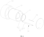
FIG. 4 is an exploded view of the atomizer shown inFIG. 3 . - Reference signs: 100. Atomizer; 10. Heating member; 11. Heating cavity; 112. First heating cavity; 114. Second heating cavity; 13. Accommodating cavity; 14. Tube body; 15. Partition plate; 16. Bottom plate; 30. Electrode assembly; 32. First electrode; 321. Discharge ring; 323. Electrical connection section; 34. Second electrode; 50. Magnetic member.
- In order to make the above objects, features and advantages of the present application clear and easier to understand, the specific embodiments of the present application are described in detail below in combination with the accompanying drawings. Many specific details are set forth in the following description to facilitate a full understanding of the present application. However, the present application can be implemented in many ways different from those described herein, and those skilled in the art can make similar improvements without departing from the connotation of the present application. Therefore, the present application is not limited by the specific embodiments disclosed below.
- In the description of the present application, it should be understood that the terms "center", "longitudinal", "transverse", "length", "width", "thickness", "upper", "lower", "front", "rear", "left", "right", "vertical", "horizontal", "top", "bottom", "inner", "outer", "clockwise", "counterclockwise", "axial", "radial", "circumferential direction" are based on the azimuth or position relationship shown in the attached drawings, which are only for the convenience of describing the present application and simplifying the description, rather than indicating or implying that the device or element must have a specific azimuth, be constructed and operated in a specific azimuth, so such terms cannot be understood as a limitation of the present application.
- In addition, the terms "first" and "second" are only used for descriptive purposes and cannot be understood as indicating or implying relative importance or implicitly indicating the number of indicated technical features. Thus, the features defined with "first" and "second" may explicitly or implicitly include at least one of the features. In the description of the present application, "a plurality of' means at least two, such as two, three, etc., unless otherwise expressly and specifically defined.
- In the present application, unless otherwise expressly specified and limited, the terms "mount", "connect", "contact", "fix" and other terms should be understood in a broad sense, for example, they can be fixed connections, detachable connections, or integrated. They can be mechanical connection or electrical connection. They can be directly connected or indirectly connected through an intermediate medium. They can be the connection within two elements or the interaction relationship between two elements, unless otherwise expressly limited. For those skilled in the art, the specific meaning of the above terms in the present application can be understood according to the specific situation.
- In the present application, unless otherwise expressly specified and limited, the first feature "above" or "below" the second feature may be in direct contact with the first and second features, or the first and second features may be in indirect contact through an intermediate medium. Moreover, the first feature is "above" the second feature, but the first feature is directly above or diagonally above the second feature, or it only means that the horizontal height of the first feature is higher than the second feature. The first feature is "below" of the second feature, which can mean that the first feature is directly below or obliquely below the second feature, or simply that the horizontal height of the first feature is less than that of the second feature.
- It should be noted that when an element is called "fixed to" or "provided on" another element, it can be directly on another element or there can be a centered element. When an element is considered to be "connected" to another element, it can be directly connected to another element or there may be intermediate elements at the same time. The terms "vertical", "horizontal", "up", "down", "left", "right" and similar expressions used herein are for the purpose of illustration only and do not represent the only embodiment.
- Referring to
FIG. 1 andFIG. 2 , anatomizer 100 according to an embodiment of the present application is shown. Theatomizer 100 heats and atomizes an aerosol-generating substrate through plasma generated by a magnetic rotating electric arc. On the one hand, the high energy density of plasma heating is utilized to achieve instant rapid heating atomization, the preheating time is effectively shortened, the scorching caused by too long preheating time is prevented, and the atomization taste is improved. On the other hand, the plasma generated by the magnetic rotating electric arc is more uniform, and a more uniform temperature field can be formed, so as to uniformly heat and atomize the aerosol-generating substrate, thereby further improving the atomization taste. - As shown in
FIG. 1 andFIG. 2 , theatomizer 100 includes aheating member 10, anelectrode assembly 30, and amagnetic member 50. Theheating member 10 forms aheating cavity 11 and anaccommodating cavity 13 in heat conduction with theheating cavity 11, and theaccommodating cavity 13 is configured to receive an aerosol-generating substrate. Theelectrode assembly 30 includes afirst electrode 32 and asecond electrode 34 both at least partially extending into theheating cavity 11. Themagnetic member 50 is provided outside theheating member 10 and configured to apply a magnetic field to theheating cavity 11. By an action of the magnetic field, a magnetic rotating electric arc rotating around an axis of theheating cavity 11 can be controllably formed between thefirst electrode 32 and thesecond electrode 34 within theheating cavity 11. - Both the
first electrode 32 and thesecond electrode 34 at least partially extend into theheating cavity 11, and after a high voltage is applied to thefirst electrode 32 and thesecond electrode 34, an electric arc can be formed between thefirst electrode 32 and thesecond electrode 34 by breakdown in theheating cavity 11. At the same time, themagnetic member 50 applies the magnetic field to theheating cavity 11, and an electric field force is applied to the electric arc to rotate the electric arc around the axis of theheating cavity 11, thereby forming the magnetic rotating electric arc. In this way, instead of forming an electric arc at a certain position of theheating cavity 11 to generate plasma heating, the rotating electric arc exists in thewhole heating cavity 11, thus forming an electric arc surface surrounding theheating cavity 11, which can heat theheating cavity 11 as a whole and form a uniform temperature field, so as to utilize plasma to efficiently and uniformly heat and atomize the aerosol-generating substrate, thereby improving the atomization taste. - In some embodiments, the
magnetic member 50 includes a magnetic ring sleeved on theheating member 10. An orthographic projection of the magnetic ring onto an axial cross-section of theheating cavity 11 covers an orthographic projection of theheating cavity 11 onto the same axial cross-section of theheating cavity 11. That is, the magnetic ring covers at least an outer periphery of theheating cavity 11, so as to apply the electric field force perpendicular to the electric arc into theheating cavity 11, so that the electric arc rotates about the axis of theheating cavity 11 under the action of the electric field force. Specifically, the magnetic ring is provided coaxially with theheating cavity 11 to form the magnetic rotating electric arc rotating around the axis of theheating cavity 11 in theheating cavity 11, so that the temperature field in theheating cavity 11 is uniform, thereby uniformly heating the aerosol-generating substrate in theaccommodating cavity 13. In addition, theheating cavity 11 and theaccommodating cavity 13 are also provided coaxially, so that the temperature field in theheating cavity 11 uniformly acts on the aerosol-generating substrate in theaccommodating cavity 13. - It should be understood that, in some other embodiments, the
magnetic member 50 may be configured to include a plurality of sub-magnets or the like arranged along a circumferential direction of theheating member 10. The specific structure of themagnetic member 50 is not limited herein, as long as the magnetic force perpendicular to the electric arc can be applied into theheating cavity 11. - In some embodiments, the
first electrode 32 includes adischarge ring 321 located in theheating cavity 11, and thedischarge ring 321 extends along an outer circumferential direction of theheating cavity 11. A discharge end of thesecond electrode 34 located in theheating cavity 11 is located on a central axis of thedischarge ring 321. In this way, thedischarge ring 321 is provided in theheating cavity 11, and an extension direction of thedischarge ring 321 is parallel to the outer circumferential direction of theheating cavity 11, which is equivalent to that thedischarge ring 321 is provided coaxially with theheating cavity 11. Then the discharge end of thesecond electrode 34 is provided on the central axis of thedischarge ring 321, as such, after the electric arc is formed between the discharge end of thesecond electrode 34 and thedischarge ring 321, the electric arc rotates circumferentially along the extension of thedischarge ring 321 under the action of the magnetic field to form the magnetic rotating electric arc, thereby uniformly heating and atomizing the aerosol-generating substrate. - Further, the discharge end of the
second electrode 34 is constructed as a cylindrical shape or a ring shape, that is, the discharge end of thesecond electrode 34 may be a cylindrical member or a ring-shaped member with a small diameter. Both the cylindrical member and the ring-shaped member are capable of performing breakdown discharge with thedischarge ring 321 in thefirst electrode 32. A discharge distance is preferably in a range of 2 mm to 8 mm. - Optionally, the
first electrode 32 and thesecond electrode 34 of theelectrode assembly 30 are both made of any one of tungsten alloy, carbon fiber, copper alloy, and graphite or any combination thereof. Diameters of thefirst electrode 32 and thesecond electrode 34 are both in a range of 0.4 mm to 1.5 mm. Optionally, a radius of thedischarge ring 321 is in the range of 3 mm to 6 mm. In some embodiments, theheating cavity 11 is filled with an inert gas. After the electric arc is generated by breakdown between thefirst electrode 32 and thesecond electrode 34 in theheating cavity 11, the inert gas filled in theheating cavity 11 can be ionized to form plasma and generate heat, and the generated heat can be efficiently transferred to theaccommodating cavity 13 through the inert gas, thereby improving the heat transfer efficiency. For example, theheating cavity 11 is filled with a gas such as helium, neon, or argon. It should be understood that in some other embodiments, theheating cavity 11 may be filled with air, which is not limited herein. - In some embodiments, an air pressure inside the
heating cavity 11 is less than a standard atmospheric pressure, so that a pressure inside theheating cavity 11 is kept at a relatively low level, and a cavity wall (i.e., the heating member 10) of theheating cavity 11 will not be subject to excessive pressure, a wall thickness and strength of theheating member 10 can be reduced, and the heat transfer efficiency can be further improved. For example, the air pressure inside theheating cavity 11 is between 1/5 of atmospheric pressure and one atmospheric pressure. Preferably, the air pressure in theheating cavity 11 is 1/5 to 1/3 of the atmospheric pressure. It should be understood that, in some other embodiments, the air pressure inside theheating cavity 11 may also be configured to be the standard atmospheric pressure, which is not limited herein. - In some embodiments, the
heating member 10 is made of an infrared radiation material. After the heat generated in theheating cavity 11 is transferred to theheating member 10, theheating member 10 can form infrared rays radiating to theaccommodating cavity 13. In this way, not only the plasma generated by the electric arc can be used to heat and atomize the aerosol-generating substrate, but also the aerosol-generating substrate can be heated and atomized by infrared radiation, thereby further improving the heating effect. Specifically, theheating member 10 is made of any one of transparent quartz glass, opal quartz, black silica quartz, silicon nitride, zirconium oxide, and aluminum oxide or any combination thereof, which can generate infrared radiation after being heated, so as to perform infrared radiation heating on the aerosol-generating substrate through theheating member 10. - Optionally, a bottom wall of the
accommodating cavity 13 faces theheating cavity 11 and is coated with an infrared radiation coating, so that more intensive infrared radiation heating can be achieved. Specifically, the infrared radiation coating made of one or more of oxide of iron, manganese and copper, CrC, TiCN, diamond-like carbon (DLC), HBQ black silicon, cordierite, transition metal oxide series spinel, rare earth oxide, ion co-doped perovskite, silicon carbide, zircon, and boron nitride. - Referring to
FIG. 1 andFIG. 2 , in some embodiments, theheating cavity 11 is located at a bottom portion of theaccommodating cavity 13 in an axial direction thereof. The discharge end of thesecond electrode 34 is coplanar with a center point of thedischarge ring 321, so as to form an electric arc extending along the radial direction of thedischarge ring 321. Finally, the electric arc rotates under the action of the magnetic field to form an electric arc surface covering an interior of thedischarge ring 321, so as to uniformly heat the bottom portion of theaccommodating cavity 13, and uniformly heat and atomize the aerosol-generating substrate in theaccommodating cavity 13. Alternatively, the discharge end of thesecond electrode 34 is lowered by a preset distance with respect to the center point of thedischarge ring 321 in a direction away from theaccommodating cavity 13, so that the electric arc forms a conical arc surface under the action of the magnetic field force, which is conducive to focusing the energy upward and further improves the uniformity of the temperature field in theheating cavity 11. Optionally, the preset distance by which thesecond electrode 34 is lowered is in a range of 0 mm to 1.0 mmm. - Further, the
heating member 10 includes atube body 14, apartition plate 15, and abottom plate 16. Thepartition plate 15 and thebottom plate 16 are spaced apart in thetube body 14 along an axial direction of thetube body 14. Theheating cavity 11 is defined among thepartition plate 15, thetube body 14, and thebottom plate 16, and theaccommodating cavity 13 is defined between a surface of thepartition plate 15 away from thebottom plate 16 and thetube body 14. In this way, theaccommodating cavity 13 and theheating cavity 11 arranged along the axial direction of thetube body 14 are formed in thetube body 14, and the aerosol-generating substrate in theaccommodating cavity 13 at the top is heated by the heat generated in theheating cavity 11. Alternatively, a thickness of thepartition plate 15 is in a range of 0.5 mm to 1.0 mm, which can satisfy the strength requirement and also can conduct heat efficiently. - Specifically, in a molding process, the
partition plate 15 and thetube body 14 may be integrally formed, and thebottom plate 16 may be fixed in thetube body 14 through a melting process after theelectrode assembly 30 is assembled. In addition, thebottom plate 16 is made of a heat-resistant material. The material of thebottom plate 16 may be the same as or different from that of thetube body 14 and thepartition plate 15, which is not limited herein. - Referring to
FIGS. 3 to 4 , in other embodiments, theheating cavity 11 includes afirst heating cavity 112 and asecond heating cavity 114 that are in communication with each other. Thefirst heating cavity 112 surrounds an outer peripheral side of theaccommodating cavity 13 in the radial direction thereof, and thesecond heating cavity 114 is located at the bottom portion of theaccommodating cavity 13 in the axial direction thereof. Thedischarge ring 321 is located in thefirst heating cavity 112 and surrounds an outer periphery of theaccommodating cavity 13. The discharge end of thesecond electrode 34 is located in thesecond heating cavity 114 and has a height difference with the center point of thedischarge ring 321. In this way, theheating cavity 11 entirely surrounds theheating cavity 11 to perform heating and atomization from an outer periphery of the aerosol-generating substrate. In addition, an electric arc passing through thefirst heating cavity 112 and thesecond heating cavity 114 can be formed between thedischarge ring 321 and the discharge end of thesecond electrode 34. The electric arc rotates around the axis of theheating cavity 11 under the action of the magnetic field force, and uniform temperature fields can be formed in both thefirst heating cavity 112 and thesecond heating cavity 114, so as to uniformly heat a side surface and a bottom surface of the aerosol-generating substrate, thereby improving the atomization taste. - In any of the above embodiments, the
first electrode 32 further includes anelectrical connection section 323 connected to thedischarge ring 321 and at least partially located in theheating cavity 11. In theheating cavity 11, a distance between theelectrical connection section 323 and thesecond electrode 34 along a radial direction of theheating cavity 11 is greater than a radial distance between thedischarge ring 321 and thesecond electrode 34. In this way, a radial distance between theelectrical connection section 323 and thesecond electrode 34 is greater than the radial distance between thedischarge ring 321 and thesecond electrode 34, so as to ensure that the discharge breakdown occurs between thedischarge ring 321 and thesecond electrode 34 with a small distance, and ensure the reliability of an ionization breakdown position. - Further, the
electrical connection section 323 is relatively insulated from thesecond electrode 34, which may further prevent ionization breakdown between theelectrical connection section 323 and thesecond electrode 34. Specifically, a heat-resistant insulating sleeve is sleeved on theelectrical connection section 323, and the heat-resistant insulating sleeve may be a ceramic tube, a quartz tube, or a high dielectric insulating film layer, so as to effectively insulate the electrical connection end 323 from thesecond electrode 34. - In any of the above embodiments, the requirement for a power supply for supplying power to the
atomizer 100 is that a current provided by the power supply always flows from one of thefirst electrode 32 and thesecond electrode 34 to the other one of thefirst electrode 32 and thesecond electrode 34 without voltage commutation. Preferably, the current is directed from thesecond electrode 34 to thefirst electrode 32 to reduce ablation loss of thesecond electrode 34 at the center. - In yet other embodiments, the
heating cavity 11 includes a third heating cavity surrounding the outer peripheral side of theaccommodating cavity 13 in the radial direction thereof. Thefirst electrode 32 and thesecond electrode 34 include a first discharge ring and a second discharge ring, respectively, both of which are located in the third heating cavity and are spaced axially around the outer periphery of theaccommodating cavity 13. In this way, theheating cavity 11 entirely surrounds theheating cavity 11 to perform heating and atomization from an outer periphery of the aerosol-generating substrate. In addition, an electric arc can be formed between the first discharge ring and the second discharge ring in thefirst heating cavity 112. The electric arc rotates along circumferential directions of the first discharge ring and the second discharge ring under the action of the magnetic field force, that is, rotates around the axis of theheating cavity 11. A uniform temperature field can be formed in thefirst heating cavity 112, so as to uniformly heat a side surface of the aerosol-generating substrate, thereby improving the atomization taste. - In an embodiment of the present application, an electronic atomization device is also provided. The electronic atomization device includes the
aforementioned atomizer 100. Theatomizer 100 includes theheating member 10, theelectrode assembly 30, and themagnetic member 50. Theheating member 10 is formed with theheating cavity 11 and theaccommodating cavity 13 in heat conduction with theheating cavity 11, and theaccommodating cavity 13 is configured to receive an aerosol-generating substrate. Theelectrode assembly 30 includes thefirst electrode 32 and thesecond electrode 34 both at least partially extending into theheating cavity 11. Themagnetic member 50 is provided outside theheating member 10 and configured to apply a magnetic field to theheating cavity 11. By the action of the magnetic field, a magnetic rotating electric arc rotating around an axis of theheating cavity 11 can be controllably formed between thefirst electrode 32 and thesecond electrode 34 within theheating cavity 11. - Both the
first electrode 32 and thesecond electrode 34 at least partially extend into theheating cavity 11, and after a high voltage is applied to thefirst electrode 32 and thesecond electrode 34, an electric arc can be formed between thefirst electrode 32 and thesecond electrode 34 by breakdown in theheating cavity 11. At the same time, themagnetic member 50 applies the magnetic field to theheating cavity 11, and an electric field force is applied to the electric arc to rotate the electric arc around the axis of theheating cavity 11, thereby forming the magnetic rotating electric arc. In this way, instead of forming an electric arc at a certain position of theheating cavity 11 to generate plasma heating, the rotating electric arc exists in thewhole heating cavity 11, thus forming an electric arc surface surrounding theheating cavity 11, which can heat theheating cavity 11 as a whole and form a uniform temperature field, so as to utilize plasma to efficiently and uniformly heat and atomize the aerosol-generating substrate, thereby improving the atomization taste.. - The above-mentioned embodiments do not constitute a limitation on the protection scope of the technical solution. Any modifications, equivalent replacements and improvements made within the spirit and principles of the above-mentioned embodiments shall be included within the protection scope of this technical solution.
- The foregoing descriptions are merely specific embodiments of the present application, but are not intended to limit the protection scope of the present application. Any variation or replacement readily figured out by a person skilled in the art within the technical scope disclosed in the present application shall all fall within the protection scope of the present application.
Claims (15)
- An atomizer, comprising:a heating member forming a heating cavity and an accommodating cavity in heat conduction with the heating cavity;an electrode assembly comprising a first electrode and a second electrode that at least partially extending into the heating cavity; anda magnetic member provided outside the heating member and configured to apply a magnetic field to the heating cavity;wherein, by an action of the magnetic field, a magnetic rotating electric arc rotating around an axis of the heating cavity is controllably formed between the first electrode and the second electrode in the heating cavity.
- The atomizer according to claim 1, wherein the magnetic member comprises a magnetic ring sleeved on the heating member, and an orthographic projection of the magnetic ring onto an axial cross-section of the heating cavity covers an orthographic projection of the heating cavity onto the same axial cross-section of the heating cavity.
- The atomizer according to claim 1, wherein the first electrode comprises a discharge ring located in the heating cavity, the discharge ring extends along an outer circumferential direction of the heating cavity, and an discharge end of the second electrode in the heating cavity is located on a central axis of the discharge ring.
- The atomizer of claim 3, wherein the discharge end of the second electrode is constructed as a cylindrical shape or a ring shape.
- The atomizer according to claim 3, wherein the heating cavity is located at a bottom portion of the accommodating cavity in an axial direction thereof, and the discharge end of the second electrode is coplanar with a center point of the discharge ring, or the discharge end of the second electrode is lowered by a preset distance with respect to the center point of the discharge ring in a direction away from the accommodating cavity.
- The atomizer according to claim 5, wherein the heating member comprises a tube body, a partition plate, and a bottom plate, the partition plate and the bottom plate are spaced apart in the tube body along an axial direction thereof, the heating cavity is defined among the partition plate, the tube body, and the bottom plate, and the accommodating cavity is defined between a surface of the partition plate away from the bottom plate and the tube body.
- The atomizer according to claim 3, wherein the heating cavity comprises a first heating cavity and a second heating cavity that are in communication with each other, the first heating cavity surrounds an outer peripheral side of the accommodating cavity in a radial direction thereof, and the second heating cavity is located at a bottom portion of the accommodating cavity in an axial direction thereof.
- The atomizer according to claim 7, wherein the discharge ring is located in the first heating cavity and surrounds an outer periphery of the accommodating cavity, and the discharge end of the second electrode is located in the second heating cavity and has a height difference with a center point of the discharge ring.
- The atomizer according to any one of claims 3 to 8, wherein the first electrode further comprises an electrical connection section connected to the discharge ring and at least partially located in the heating cavity;
wherein in the heating cavity, a distance between the electrical connection section and the second electrode along a radial direction of the heating cavity is greater than a radial distance between the discharge ring and the second electrode. - The atomizer according to claim 9, wherein the electrical connection section is relatively insulated from the second electrode.
- The atomizer according to claim 1, wherein the heating cavity comprises a third heating cavity surrounding an outer peripheral side of the accommodating cavity in a radial direction thereof.
- The atomizer according to claim 11, wherein the first electrode comprises a first discharge ring, the second electrode comprises a second discharge ring, and the first discharge ring and the second discharge ring are both located in the third heating cavity and are both spaced axially around an outer periphery of the accommodating cavity.
- The atomizer according to any one of claims 1 to 8, wherein the heating member is made of an infrared radiation material.
- The atomizer according to any one of claims 1 to 8, wherein a bottom wall of the accommodating cavity faces the heating cavity and is coated with an infrared radiation coating.
- An electronic atomization device, comprising the atomizer according to any one of claims 1 to 14.
Applications Claiming Priority (2)
| Application Number | Priority Date | Filing Date | Title |
|---|---|---|---|
| CN202220266372.9U CN217117529U (en) | 2022-02-09 | 2022-02-09 | Atomizer and electronic atomization device |
| PCT/CN2022/131044 WO2023151328A1 (en) | 2022-02-09 | 2022-11-10 | Atomizer and electronic atomization device |
Publications (2)
| Publication Number | Publication Date |
|---|---|
| EP4445770A1 true EP4445770A1 (en) | 2024-10-16 |
| EP4445770A4 EP4445770A4 (en) | 2025-05-07 |
Family
ID=82622033
Family Applications (1)
| Application Number | Title | Priority Date | Filing Date |
|---|---|---|---|
| EP22925679.7A Pending EP4445770A4 (en) | 2022-02-09 | 2022-11-10 | Atomizer and electronic atomization device |
Country Status (4)
| Country | Link |
|---|---|
| EP (1) | EP4445770A4 (en) |
| JP (1) | JP7719307B2 (en) |
| CN (1) | CN217117529U (en) |
| WO (1) | WO2023151328A1 (en) |
Families Citing this family (11)
| Publication number | Priority date | Publication date | Assignee | Title |
|---|---|---|---|---|
| CN217117529U (en) * | 2022-02-09 | 2022-08-05 | 深圳麦克韦尔科技有限公司 | Atomizer and electronic atomization device |
| CN115297601A (en) * | 2022-08-16 | 2022-11-04 | 海南摩尔兄弟科技有限公司 | Plasma heating structure and plasma atomizing device |
| CN115297602A (en) * | 2022-08-16 | 2022-11-04 | 海南摩尔兄弟科技有限公司 | Plasma heating structure and plasma atomizing device |
| CN218898365U (en) * | 2022-11-28 | 2023-04-25 | 深圳麦克韦尔科技有限公司 | Electrode and electronic atomization device |
| CN219373809U (en) * | 2022-11-28 | 2023-07-21 | 深圳麦克韦尔科技有限公司 | Electronic atomizing device |
| CN115736376A (en) * | 2022-11-30 | 2023-03-07 | 思摩尔国际控股有限公司 | Heating element, electronic atomization device and atomization method |
| CN116035280B (en) * | 2023-01-05 | 2026-04-17 | 深圳市赛尔美电子科技有限公司 | Apparatus for manufacturing heating structure, method for manufacturing heating structure and heating structure |
| CN116671675A (en) * | 2023-05-18 | 2023-09-01 | 湖北中烟工业有限责任公司 | An aerosol generating device |
| WO2025051023A1 (en) * | 2023-09-08 | 2025-03-13 | 思摩尔国际控股有限公司 | Heating assembly and aerosol generating device |
| CN120345739A (en) * | 2024-01-22 | 2025-07-22 | 沃德韦国际控股有限公司 | Heating module and aerosol generating device |
| CN120345736A (en) * | 2024-01-22 | 2025-07-22 | 沃德韦国际控股有限公司 | Heating module and aerosol generating device |
Family Cites Families (13)
| Publication number | Priority date | Publication date | Assignee | Title |
|---|---|---|---|---|
| EP0002623B1 (en) | 1977-12-20 | 1983-09-07 | National Research Development Corporation | Electric arc apparatus and method for treating a flow of material by an electric arc |
| JPS5546266A (en) * | 1978-09-28 | 1980-03-31 | Daido Steel Co Ltd | Plasma torch |
| JPS62192270A (en) * | 1986-02-19 | 1987-08-22 | Mitsubishi Heavy Ind Ltd | Plasma torch |
| JP4821826B2 (en) * | 2008-09-25 | 2011-11-24 | パナソニック電工株式会社 | Electrostatic atomizer |
| CN203801738U (en) * | 2014-05-08 | 2014-09-03 | 梁艳明 | Arc ignition atomizer and electronic cigarette |
| CN203952435U (en) | 2014-05-27 | 2014-11-26 | 李述彦 | Electronic smoke atomizer and electronic cigarette |
| CN204579893U (en) | 2015-04-02 | 2015-08-26 | 赵惠萍 | Electronic smoke atomizer |
| CN106376973A (en) * | 2016-06-17 | 2017-02-08 | 深圳瀚星翔科技有限公司 | Electronic atomizer and electronic atomizing device |
| US20190357593A1 (en) * | 2018-05-25 | 2019-11-28 | Acoustic Arc International Limited | Electronic Cigarette |
| CN109010880A (en) * | 2018-08-28 | 2018-12-18 | 汤米环境解决方案公司 | A kind of plasma atomization disinfection nozzle |
| CN209127017U (en) * | 2018-11-15 | 2019-07-19 | 深圳市优维尔科技有限公司 | Electric arc atomization device device |
| CN215603176U (en) * | 2021-01-14 | 2022-01-25 | 深圳麦克韦尔科技有限公司 | Electronic atomization device, battery assembly and atomizer |
| CN217117529U (en) * | 2022-02-09 | 2022-08-05 | 深圳麦克韦尔科技有限公司 | Atomizer and electronic atomization device |
-
2022
- 2022-02-09 CN CN202220266372.9U patent/CN217117529U/en active Active
- 2022-11-10 WO PCT/CN2022/131044 patent/WO2023151328A1/en not_active Ceased
- 2022-11-10 EP EP22925679.7A patent/EP4445770A4/en active Pending
- 2022-11-10 JP JP2024541039A patent/JP7719307B2/en active Active
Also Published As
| Publication number | Publication date |
|---|---|
| WO2023151328A1 (en) | 2023-08-17 |
| JP2025501371A (en) | 2025-01-17 |
| CN217117529U (en) | 2022-08-05 |
| EP4445770A4 (en) | 2025-05-07 |
| JP7719307B2 (en) | 2025-08-05 |
Similar Documents
| Publication | Publication Date | Title |
|---|---|---|
| JP7719307B2 (en) | Atomizers and electronic atomizers | |
| JP7844672B2 (en) | Heater and heating atomizer | |
| EP4494500A1 (en) | Heating body and heating atomization device | |
| CN101227790B (en) | Plasma jet apparatus | |
| JPH0219600B2 (en) | ||
| US2438561A (en) | Electrothermal deposition apparatus | |
| CN217509910U (en) | Heating element and electronic atomization device | |
| US20250275575A1 (en) | Aerosol-generating device and heating structure | |
| EP4464181A1 (en) | Atomizer and electronic atomization device | |
| CN219373809U (en) | Electronic atomizing device | |
| CN217089631U (en) | Heating element and electronic atomization device | |
| WO2024055731A1 (en) | Heating assembly and aerosol generating device | |
| CN218921711U (en) | Electronic atomizing device | |
| WO2023207296A1 (en) | Aerosol generation device and heating assembly | |
| WO2024114147A1 (en) | Heating element, electronic atomization apparatus, and atomization method | |
| JP7737558B2 (en) | Atomizer and electronic atomizer | |
| JP2025520897A (en) | Heating assembly and aerosol generating device | |
| US3780255A (en) | Apparatus for heat treatment of substrates | |
| WO2024055720A1 (en) | Heating assembly and aerosol generating device | |
| US20250275580A1 (en) | Aerosol generating device and heating structure thereof | |
| CN220140823U (en) | Heating elements and electronic atomization devices | |
| US20240237746A1 (en) | Electronic vaporization device and vaporizer thereof | |
| JPH11354291A (en) | Plasma generator | |
| JP3304861B2 (en) | Cesium sputter type negative ion source | |
| WO2023124522A1 (en) | Atomization apparatus, atomizer thereof, and heating element |
Legal Events
| Date | Code | Title | Description |
|---|---|---|---|
| STAA | Information on the status of an ep patent application or granted ep patent |
Free format text: STATUS: THE INTERNATIONAL PUBLICATION HAS BEEN MADE |
|
| PUAI | Public reference made under article 153(3) epc to a published international application that has entered the european phase |
Free format text: ORIGINAL CODE: 0009012 |
|
| STAA | Information on the status of an ep patent application or granted ep patent |
Free format text: STATUS: REQUEST FOR EXAMINATION WAS MADE |
|
| 17P | Request for examination filed |
Effective date: 20240708 |
|
| AK | Designated contracting states |
Kind code of ref document: A1 Designated state(s): AL AT BE BG CH CY CZ DE DK EE ES FI FR GB GR HR HU IE IS IT LI LT LU LV MC ME MK MT NL NO PL PT RO RS SE SI SK SM TR |
|
| RAP3 | Party data changed (applicant data changed or rights of an application transferred) |
Owner name: SHENZHEN SMOORE TECHNOLOGY LIMITED |
|
| A4 | Supplementary search report drawn up and despatched |
Effective date: 20250407 |
|
| RIC1 | Information provided on ipc code assigned before grant |
Ipc: H05B 7/18 20060101ALI20250401BHEP Ipc: A24F 40/46 20200101ALI20250401BHEP Ipc: A24F 40/40 20200101AFI20250401BHEP |
|
| DAV | Request for validation of the european patent (deleted) | ||
| DAX | Request for extension of the european patent (deleted) | ||
| RAP3 | Party data changed (applicant data changed or rights of an application transferred) |
Owner name: SHENZHEN SMOORE TECHNOLOGY LIMITED |