EP4445768A1 - Aerosol generation apparatus and control method and apparatus therefor, and readable storage medium - Google Patents
Aerosol generation apparatus and control method and apparatus therefor, and readable storage medium Download PDFInfo
- Publication number
- EP4445768A1 EP4445768A1 EP22903078.8A EP22903078A EP4445768A1 EP 4445768 A1 EP4445768 A1 EP 4445768A1 EP 22903078 A EP22903078 A EP 22903078A EP 4445768 A1 EP4445768 A1 EP 4445768A1
- Authority
- EP
- European Patent Office
- Prior art keywords
- assembly
- frequency
- microwave
- generating device
- aerosol generating
- Prior art date
- Legal status (The legal status is an assumption and is not a legal conclusion. Google has not performed a legal analysis and makes no representation as to the accuracy of the status listed.)
- Pending
Links
Images



Classifications
-
- A—HUMAN NECESSITIES
- A24—TOBACCO; CIGARS; CIGARETTES; SIMULATED SMOKING DEVICES; SMOKERS' REQUISITES
- A24F—SMOKERS' REQUISITES; MATCH BOXES; SIMULATED SMOKING DEVICES
- A24F40/00—Electrically operated smoking devices; Component parts thereof; Manufacture thereof; Maintenance or testing thereof; Charging means specially adapted therefor
- A24F40/50—Control or monitoring
-
- A—HUMAN NECESSITIES
- A24—TOBACCO; CIGARS; CIGARETTES; SIMULATED SMOKING DEVICES; SMOKERS' REQUISITES
- A24F—SMOKERS' REQUISITES; MATCH BOXES; SIMULATED SMOKING DEVICES
- A24F40/00—Electrically operated smoking devices; Component parts thereof; Manufacture thereof; Maintenance or testing thereof; Charging means specially adapted therefor
- A24F40/40—Constructional details, e.g. connection of cartridges and battery parts
-
- A—HUMAN NECESSITIES
- A24—TOBACCO; CIGARS; CIGARETTES; SIMULATED SMOKING DEVICES; SMOKERS' REQUISITES
- A24F—SMOKERS' REQUISITES; MATCH BOXES; SIMULATED SMOKING DEVICES
- A24F40/00—Electrically operated smoking devices; Component parts thereof; Manufacture thereof; Maintenance or testing thereof; Charging means specially adapted therefor
- A24F40/40—Constructional details, e.g. connection of cartridges and battery parts
- A24F40/46—Shape or structure of electric heating means
-
- A—HUMAN NECESSITIES
- A24—TOBACCO; CIGARS; CIGARETTES; SIMULATED SMOKING DEVICES; SMOKERS' REQUISITES
- A24F—SMOKERS' REQUISITES; MATCH BOXES; SIMULATED SMOKING DEVICES
- A24F40/00—Electrically operated smoking devices; Component parts thereof; Manufacture thereof; Maintenance or testing thereof; Charging means specially adapted therefor
- A24F40/50—Control or monitoring
- A24F40/53—Monitoring, e.g. fault detection
-
- A—HUMAN NECESSITIES
- A24—TOBACCO; CIGARS; CIGARETTES; SIMULATED SMOKING DEVICES; SMOKERS' REQUISITES
- A24F—SMOKERS' REQUISITES; MATCH BOXES; SIMULATED SMOKING DEVICES
- A24F40/00—Electrically operated smoking devices; Component parts thereof; Manufacture thereof; Maintenance or testing thereof; Charging means specially adapted therefor
- A24F40/50—Control or monitoring
- A24F40/57—Temperature control
-
- H—ELECTRICITY
- H05—ELECTRIC TECHNIQUES NOT OTHERWISE PROVIDED FOR
- H05B—ELECTRIC HEATING; ELECTRIC LIGHT SOURCES NOT OTHERWISE PROVIDED FOR; CIRCUIT ARRANGEMENTS FOR ELECTRIC LIGHT SOURCES, IN GENERAL
- H05B6/00—Heating by electric, magnetic or electromagnetic fields
- H05B6/64—Heating using microwaves
-
- H—ELECTRICITY
- H05—ELECTRIC TECHNIQUES NOT OTHERWISE PROVIDED FOR
- H05B—ELECTRIC HEATING; ELECTRIC LIGHT SOURCES NOT OTHERWISE PROVIDED FOR; CIRCUIT ARRANGEMENTS FOR ELECTRIC LIGHT SOURCES, IN GENERAL
- H05B6/00—Heating by electric, magnetic or electromagnetic fields
- H05B6/64—Heating using microwaves
- H05B6/6402—Aspects relating to the microwave cavity
-
- H—ELECTRICITY
- H05—ELECTRIC TECHNIQUES NOT OTHERWISE PROVIDED FOR
- H05B—ELECTRIC HEATING; ELECTRIC LIGHT SOURCES NOT OTHERWISE PROVIDED FOR; CIRCUIT ARRANGEMENTS FOR ELECTRIC LIGHT SOURCES, IN GENERAL
- H05B6/00—Heating by electric, magnetic or electromagnetic fields
- H05B6/64—Heating using microwaves
- H05B6/66—Circuits
-
- H—ELECTRICITY
- H05—ELECTRIC TECHNIQUES NOT OTHERWISE PROVIDED FOR
- H05B—ELECTRIC HEATING; ELECTRIC LIGHT SOURCES NOT OTHERWISE PROVIDED FOR; CIRCUIT ARRANGEMENTS FOR ELECTRIC LIGHT SOURCES, IN GENERAL
- H05B6/00—Heating by electric, magnetic or electromagnetic fields
- H05B6/64—Heating using microwaves
- H05B6/66—Circuits
- H05B6/68—Circuits for monitoring or control
-
- A—HUMAN NECESSITIES
- A24—TOBACCO; CIGARS; CIGARETTES; SIMULATED SMOKING DEVICES; SMOKERS' REQUISITES
- A24F—SMOKERS' REQUISITES; MATCH BOXES; SIMULATED SMOKING DEVICES
- A24F40/00—Electrically operated smoking devices; Component parts thereof; Manufacture thereof; Maintenance or testing thereof; Charging means specially adapted therefor
- A24F40/20—Devices using solid inhalable precursors
Definitions
- the present disclosure relates to the field of electronic cigarette, and more specifically, to an aerosol generating device, control method thereof, control device and readable storage medium.
- a heat-not-burn (HNB) device is a combination of heating device and aerosol-generating substrate (a processed plant leaf product).
- the external heating device can heat the aerosol-generating substrate to a high temperature at which the aerosol-generating substrate can generate aerosol but does not burn, so that the aerosol-generating substrate can generate the aerosol required a user on the premise of not burning.
- the HNB device in the market mainly adopts a resistance heating mode, which uses a central heating sheet or a central heating needle or the like to insert into the aerosol-forming substrate for heating.
- This device needs a long preheating waiting time before use, and cannot be smoked and stopped freely.
- the carbonization of the aerosol-forming substrate is uneven, resulting in insufficient baking and a low utilization rate of the aerosol-forming substrate.
- the heating sheet of the HNB device is prone to generating dirt in the aerosol-forming substrate extractor and the heating sheet base, making it difficult to clean.
- the local aerosol-forming substrate in contact with the heating sheet is too high in temperature, leading to a partial cracking to produce harmful substances to the human body.
- the microwave heating technology gradually replaces the resistance heating mode to become a new heating mode.
- the microwave heating technology has the characteristics of high efficiency, timeliness, selectivity, and no delay in heating, and only has a heating effect on substances having specific dielectric properties.
- the advantages of using the microwave heating for atomization are as follows: a. the microwave heating is radiation heating and non-heat conduction, and instant smoking and stopping can be achieved; b. no heating sheet exists, so that the problems of sheet breaking and heating sheet cleaning do not exist; c. the aerosol-forming substrate is high in utilization rate, high in taste consistency, and closer to a cigarette in taste.
- the aerosol generating device always determines the optimal frequency point of the microwave assembly by detecting the standing-wave ratio through the circulator.
- the miniaturization design of the aerosol generating device cannot be satisfied due to the large volume of the circulator.
- the present disclosure aims to solve one of the technical problems existing in the prior art or related technologies.
- an aerosol generating device is provided in the first aspect of the present disclosure.
- a control method of the aerosol generating device is provided in the second aspect of the present disclosure.
- a control device of the aerosol generating device is provided in the third aspect of the present disclosure.
- a control device of the aerosol generating device is provided in the fourth aspect of the present disclosure.
- a readable storage medium is provided in the fifth aspect of the present disclosure.
- An aerosol generating device is provided in the sixth aspect of the present disclosure.
- an aerosol generating device comprising: a shell comprising an atomization cavity; a microwave assembly connected to the shell and configured to feed a microwave into the atomization cavity; a voltage acquisition assembly arranged in the atomization cavity and configured to acquire the feedback voltage values of the atomization cavity; and a controller connected to the voltage acquisition assembly and configured to determine the target operating frequency of the microwave assembly according to the feedback voltage value.
- the aerosol generating device comprises a shell, a microwave assembly, a voltage acquisition assembly, and a controller.
- An atomization cavity is arranged in the shell, and an aerosol-generating substrate can be accommodated in the atomization cavity.
- the microwave assembly is installed on the shell, and the microwave assembly can feed a microwave into the atomization cavity.
- the aerosol-generating substrate accommodated in the atomization cavity can be heated and atomized under the action of microwaves fed by the microwave assembly.
- the microwave generated by the microwave assembly generates current in the wall structure of the atomization cavity due to the resonance characteristics of the atomization cavity.
- the feedback voltage value of the current on the wall structure of the atomization cavity can be acquired by the voltage acquisition assembly, the voltage acquisition assembly transmits the feedback voltage value to the controller, and the controller can judge the energy at the wall of the atomization cavity according to the feedback voltage value.
- the voltage acquisition assembly continuously acquires the feedback voltage values on the wall of the atomization cavity, and the controller records the acquired feedback voltage values after the frequency sweeping operation of the microwave assembly.
- the controller compares the sizes of multiple feedback voltage values, and takes the operating frequency corresponding to the largest feedback voltage value among the multiple feedback voltage values as the target operating frequency. Understandably, if the feedback voltage value is large, it means that the microwave with the current frequency feeds more energy into the atomization cavity, so the operating frequency corresponding to the maximum feedback voltage value is the resonance frequency of the atomization cavity. Therefore, controlling the microwave assembly to operate according to the operating frequency corresponding to the maximum feedback voltage value can make the microwave assembly operate at the optimal frequency point, and improve the heating atomization efficiency of the aerosol generating device on the aerosol-generating substrate.
- the microwave-generating assembly is controlled to conduct the frequency sweeping operation within the set frequency range, and the minimum frequency of the set frequency range is 2.2G, and the maximum frequency is 2.57G.
- the microwave assembly starts operating from the minimum frequency, and the microwave assembly is controlled to increase by 10MHz every 2ms until the maximum frequency is reached. Every time when the operating frequency is switched, a feedback voltage value will be recorded. After the frequency sweeping is completed, the operating frequency corresponding to the maximum value of the feedback voltage is taken as the target operating frequency, and the microwave assembly is controlled to feed a microwave into the atomization cavity according to the target operating frequency.
- a circulator for detecting the standing-wave ratio is always arranged in the aerosol generating device, which takes up a large space in the aerosol generating device, generates heat during the operation of the circulator and thus results in a decrease in the efficiency of the whole system.
- the voltage acquisition assembly capable of acquiring the feedback voltage values at the cavity wall of the atomization cavity is arranged in the atomization cavity, so that the controller can determine the currently fed energy in the atomization cavity according to the feedback voltage value and determine the resonance frequency of the atomization cavity. That is, the optimal frequency point for the operation of the microwave assembly. Controlling the atomization assembly according to the optimal frequency point can improve the heating atomization efficiency of the aerosol generating device on the aerosol-generating substrate.
- the present disclosure can ensure the accuracy and detection efficiency of the detected optimal frequency point of the microwave assembly, and there is no need to additionally arrange a circulator with a large volume in the atomization cavity. This is beneficial to the miniaturization of products and helps reduce the production cost.
- the voltage acquisition assembly will not generate lots of heat during the operation process, which ensures the operation efficiency of the aerosol generating device.
- aerosol generating device in the above technical solution provided in the present disclosure may have the following additional technical features:
- the voltage acquisition assembly comprises: a feed point arranged on the inner wall of the shell; and a filter assembly.
- the first end of the filter assembly is connected to the feed point, and the second end of the filter assembly is connected to the controller.
- the voltage acquisition assembly comprises a feed point and a filter assembly.
- a feed point is arranged on the inner wall of the shell. That is, a feed point is arranged in the inner cavity of the atomization cavity.
- the voltage signal at the inner side wall of the atomization cavity is acquired through the feed point, and the voltage signal is filtered by the filter assembly and transmitted to the controller, so that the controller can acquire the feedback voltage values at the atomization cavity through the feed point.
- the feed point is arranged in the atomization cavity, so that the feedback voltage values at the cavity wall of the atomization cavity are acquired.
- the filter assembly comprises: a diode, the first end of the diode is connected to the feed point, and the second end of the diode is grounded; a filter circuit, the first end of the filter circuit is connected to the first end of the diode, the second end of the filter assembly is connected to the second end of the diode, and the filter circuit is connected to the controller; wherein, the second end of the diode is conducted to the first end.
- the filter assembly comprises a diode and a filter circuit.
- the diode is a rectifier diode, and the current at the inner wall of the atomization cavity is rectified into a DC signal.
- the DC signal is filtered by the filter circuit, and the filtered DC signal is transmitted to the controller.
- the filtered DC signal received by the controller can determine the feedback voltage value at the cavity wall of the atomization cavity.
- the diode is connected in parallel to the filter circuit.
- the first end of the diode is the cathode of the diode, the cathode of the diode is connected to the feed point, the anode of the diode is connected to the grounding terminal, and the controller is connected to the rectifier circuit.
- the feedback voltage values of the negative current on the cavity wall of the atomization cavity can be acquired through the cathode of the diode.
- the diode is arranged in parallel with the filter circuit, and the cathode of the diode is connected to the feed point, so that the filter assembly can acquire the feedback voltage values of the negative current on the cavity wall of the atomization cavity through the feed point.
- the filter assembly comprises a diode, the first end of the diode is connected to the feed point; a filter circuit, the first end of the filter circuit is connected to the second end of the diode, the second end of the filter circuit is grounded, and the filter circuit is connected to the controller; wherein, the first end of the diode is conducted to the second end.
- the filter assembly comprises a diode and a filter circuit.
- the diode is a rectifier diode, and the current at the inner wall of the atomization cavity is rectified into a DC signal.
- the DC signal is filtered by the filter circuit, and the filtered DC signal is transmitted to the controller.
- the filtered DC signal received by the controller can determine the feedback voltage value at the cavity wall of the atomization cavity.
- the diode is connected in series to the filter circuit.
- the first end of the diode is the anode of the diode, the anode of the diode is connected to the feed point, and the cathode of the diode is connected to the controller through the rectifier circuit.
- the feedback voltage values of the forward current on the cavity wall of the atomization cavity can be acquired through the anode of the diode.
- the diode is arranged in series with the filter circuit, and the anode of the diode is connected to the feed point, so that the filter assembly can acquire the feedback voltage values of the forward current on the cavity wall of the atomization cavity through the feed point.
- the filter circuit comprises any one or a combination of the following: capacitor filter circuit, resistor-capacitor filter circuit, and inductor-capacitor filter circuit.
- the filter circuit is selected as a DC filter circuit. Specifically, it can be any one or a combination of capacitor filter circuit, resistor-capacitor filter circuit (RC), and inductor-capacitor filter circuit (LC).
- RC resistor-capacitor filter circuit
- LC inductor-capacitor filter circuit
- the filter circuit is selected as an inductor-capacitor filter circuit, and the diode is connected in series to the inductor-capacitor filter circuit.
- the first end of the diode is connected to the feed point
- the second end of the diode is connected in series to the inductor and capacitor
- the capacitor is connected to the controller
- the capacitor and the common terminal of the controller are grounded.
- the diode is conducted from the first end to the second end.
- the current at the cavity wall of the atomization cavity is rectified by the diode to become a direct current signal
- the direct current signal is filtered by the inductor-capacitor filter circuit and then transmitted to the controller, and the controller can obtain a feedback voltage value by processing the direct current signal.
- the feed point comprises: a through hole arranged on the bottom wall of the atomization cavity, and the filter assembly connected to the hole wall of the through hole; or a conducting ring arranged on the inner wall of the atomization cavity, the conducting ring close to the bottom wall of the atomization cavity, and the filter assembly connected to the conducting ring; or a lead, the first end of the lead connected to the bottom wall of the atomization cavity, and the second end of the lead connected to the filter assembly.
- the feed point can be optionally set in various forms, comprising but not limited to through hole, conducting ring and lead.
- the feed point is set as a through hole, and the through hole is set at the bottom wall of the atomization cavity, and the sampling end of the filter assembly is connected to the hole wall of the through hole to acquire the feedback voltage values at the hole wall position of the bottom wall of the atomization cavity.
- the feed point is set as a conducting ring
- the conducting ring can be specifically selected as a copper ring.
- the conducting ring is arranged on the inner side wall of the atomization cavity and near the bottom wall of the atomization cavity.
- the sampling end of the filter assembly is connected to the conducting ring, the conducting ring is arranged at the cavity wall of the atomization cavity, and the conducting ring can lead the current at the cavity wall to the filter assembly, so that the feedback voltage values at the cavity wall of the atomization cavity can be acquired through the conducting ring.
- a control method of the aerosol generating device is provided in the second aspect of the present disclosure.
- the aerosol generating device comprises a microwave assembly, an atomization cavity and a voltage acquisition assembly.
- the control method of the aerosol generating device comprises the following steps: control the microwave assembly to conduct the frequency sweeping operation within the set frequency range; acquire multiple feedback voltage values of the atomization cavity through the voltage acquisition assembly when the microwave assembly is under the frequency sweeping operation; determine a target frequency within the set frequency range according to multiple feedback voltage values; and control the microwave assembly to operate according to the target frequency.
- the control method of the aerosol generating device controls the aerosol generating device.
- the aerosol generating device comprises a shell, a microwave assembly, a voltage acquisition assembly, and a controller.
- An atomization cavity is arranged in the shell, and an aerosol-generating substrate can be accommodated in the atomization cavity.
- the microwave assembly is installed on the shell, and the microwave assembly can feed a microwave into the atomization cavity.
- the aerosol-generating substrate accommodated in the atomization cavity can be heated and atomized under the action of microwaves fed by the microwave assembly.
- the microwave generated by the microwave assembly will generate current in the wall structure of the atomization cavity due to the resonance characteristics of the atomization cavity.
- the microwave assembly When the aerosol-generating substrate is located in the atomization cavity, the microwave assembly is controlled to start frequency sweeping operation within the set frequency range.
- multiple feedback voltage values at the cavity wall of the atomization cavity are continuously acquired by the voltage acquisition assembly. Understandably, multiple feedback voltage values correspond to multiple operating frequencies in the process of frequency sweeping operation of the microwave component.
- the target frequency within the set frequency range can be obtained.
- the microwave assembly is controlled to feed a microwave into the atomization cavity according to the target frequency, so as to heat and atomize the aerosol-generating substrate in the atomization cavity.
- the target frequency is the operating frequency closest to the resonance frequency of the cavity in the RF frequency range. That is, the optimal frequency point during the operation of the microwave assembly. Controlling the aerosol generating device to feed a microwave into the atomization cavity according to the target frequency can improve the atomization efficiency of the aerosol-generating substrate in the atomization cavity.
- a circulator for detecting the standing-wave ratio is always arranged in the aerosol generating device, which takes up a large space in the aerosol generating device, generates heat during the operation of the circulator and thus results in a decrease in the efficiency of the whole system.
- the voltage acquisition assembly capable of acquiring the feedback voltage values at the cavity wall of the atomization cavity is arranged in the atomization cavity, so that the controller can determine the currently fed energy in the atomization cavity according to the feedback voltage value and determine the resonance frequency of the atomization cavity. That is, the optimal frequency point for the operation of the microwave assembly. Controlling the atomization assembly according to the optimal frequency point can improve the heating atomization efficiency of the aerosol generating device on the aerosol-generating substrate.
- the present disclosure can ensure the accuracy and detection efficiency of the detected optimal frequency point of the microwave assembly, and there is no need to additionally arrange a circulator with a large volume in the atomization cavity. This is beneficial to the miniaturization of products and helps reduce the production cost.
- the voltage acquisition assembly will not generate lots of heat during the operation process, which ensures the operation efficiency of the aerosol generating device.
- control method of the aerosol generating device in the above technical solutions provided in the present disclosure may have the following additional technical features:
- the target frequency within the set frequency range is determined according to the feedback voltage value, which further comprises: obtain the maximum voltage value among multiple feedback voltage values; determine the target frequency corresponding to the maximum voltage value within the set frequency range according to the maximum voltage value.
- the voltage acquisition assembly continuously acquires the feedback voltage values on the wall of the atomization cavity, and the controller records the acquired feedback voltage values after the frequency sweeping operation of the microwave assembly.
- the controller compares the sizes of multiple feedback voltage values, and takes the operating frequency corresponding to the largest feedback voltage value among the multiple feedback voltage values as the target operating frequency.
- the microwave assembly can make the microwave assembly operate at the optimal frequency point, and improve the heating atomization efficiency of the aerosol generating device on the aerosol-generating substrate.
- the steps for controlling the microwave assembly to conduct the frequency sweeping operation within the set frequency range include: control the microwave assembly to start operating at a first frequency within the set frequency range; adjust the operating frequency of the microwave assembly according to the set adjustment value every the first set time until the operating frequency reaches a second frequency within the set frequency range.
- control the microwave assembly to conduct the frequency sweeping operation within the set frequency range. Specifically, control the microwave assembly to start operating at a lower first frequency within the set frequency range, and control the microwave assembly to adjust the operating frequency to a set adjustment value every the first set time until it is adjusted to a second frequency within the set frequency range.
- the first frequency is greater than the second frequency, or the first frequency is less than the second frequency. That is, the microwave assembly can operate from low to high frequency within the set frequency range, or from high to low frequency within the set frequency range.
- the microwave-generating assembly is controlled to conduct the frequency sweeping operation within the set frequency range, and the minimum frequency of the set frequency range is 2.2G, and the maximum frequency is 2.57G.
- the microwave assembly starts operating from the minimum frequency, and the microwave assembly is controlled to increase by 10MHz every 2ms until the maximum frequency is reached. Every time when the operating frequency is switched, a feedback voltage value will be recorded. After the frequency sweeping is completed, the operating frequency corresponding to the maximum value of the feedback voltage is taken as the target operating frequency, and the microwave assembly is controlled to feed a microwave into the atomization cavity according to the target operating frequency.
- the operating frequency of the microwave assembly is controlled to adjust the set adjustment value every the first set time, so that there is enough time for the microwave assembly to feed a microwave into the atomization cavity at every operating frequency, the correspondence between multiple feedback voltage values and multiple operating frequencies within the set frequency range is improved, and the accuracy of obtaining the target frequency is further improved.
- the steps for acquiring multiple feedback voltage values of the atomization cavity through the voltage acquisition assembly when the microwave assembly is under the frequency sweeping operation comprises: acquire the feedback voltage values of the atomization cavity every the first set time when the microwave assembly is in the operation state.
- the feedback voltage value of the atomization cavity is acquired every the first set time in the process of frequency sweeping operation.
- the acquired multiple feedback voltage values can be matched with the operating frequencies within the set frequency range, which is convenient for finding the accurate target frequency according to the maximum voltage value among the multiple feedback voltage values.
- the voltage acquisition assembly continuously detects the feedback voltage value of the atomization cavity, and records the current feedback voltage value every the first set time.
- the voltage acquisition assembly detects and records the current feedback voltage value every the first set time.
- after the steps for controlling the microwave assembly to operate according to the target frequency further comprises: return to the step of controlling the microwave assembly to operate within the set frequency range until the stop instruction is received when the microwave assembly is operated at the target frequency for a second set time.
- control the microwave assembly to operate for a second set time according to the target frequency, and then return the step of controlling the microwave assembly to sweep the frequency to search the target frequency again.
- the aerosol-generating substrate in the aerosol generating device is heated and atomized along with the operation of the microwave assembly, the aerosol-generating substrate in the atomization cavity changes, and the resonance frequency of the atomization cavity changes as well.
- the microwave assembly in the aerosol generating device can work at the optimal frequency point for a long time, and the atomization effect of the aerosol generating device on the aerosol-generating substrate is improved.
- a control device of the aerosol generating device comprises a microwave assembly, an atomization cavity and a voltage acquisition assembly.
- the control device of the aerosol generating device comprises: a control module configured to control the microwave assembly to conduct the frequency sweeping operation within the set frequency range; an acquisition module configured to acquire multiple feedback voltage values of the atomization cavity through the voltage acquisition assembly when the microwave assembly is under the frequency sweeping operation; a determining module configured to determine a target frequency within the set frequency range according to multiple feedback voltage values; and a determining module further configured to control the microwave assembly to operate according to the target frequency.
- the control device of the aerosol generating device controls the aerosol generating device.
- the aerosol generating device comprises a shell, a microwave assembly, a voltage acquisition assembly, and a controller.
- An atomization cavity is arranged in the shell, and an aerosol-generating substrate can be accommodated in the atomization cavity.
- the microwave assembly is installed on the shell, and the microwave assembly can feed a microwave into the atomization cavity.
- the aerosol-generating substrate accommodated in the atomization cavity can be heated and atomized under the action of microwaves fed by the microwave assembly.
- the microwave generated by the microwave assembly will generate current in the wall structure of the atomization cavity due to the resonance characteristics of the atomization cavity.
- the target frequency is the operating frequency closest to the resonance frequency of the cavity in the RF frequency range. That is, the optimal frequency point during the operation of the microwave assembly. Controlling the aerosol generating device to feed a microwave into the atomization cavity according to the target frequency can improve the atomization efficiency of the aerosol-generating substrate in the atomization cavity.
- a circulator for detecting the standing-wave ratio is always arranged in the aerosol generating device, which takes up a large space in the aerosol generating device, generates heat during the operation of the circulator and thus results in a decrease in the efficiency of the whole system.
- the voltage acquisition assembly capable of acquiring the feedback voltage values at the cavity wall of the atomization cavity is arranged in the atomization cavity, so that the controller can determine the currently fed energy in the atomization cavity according to the feedback voltage value and determine the resonance frequency of the atomization cavity. That is, the optimal frequency point for the operation of the microwave assembly. Controlling the atomization assembly according to the optimal frequency point can improve the heating atomization efficiency of the aerosol generating device on the aerosol-generating substrate.
- the present disclosure can ensure the accuracy and detection efficiency of the detected optimal frequency point of the microwave assembly, and there is no need to additionally arrange a circulator with a large volume in the atomization cavity. This is beneficial to the miniaturization of products and helps reduce the production cost.
- the voltage acquisition assembly will not generate lots of heat during the operation process, which ensures the operation efficiency of the aerosol generating device.
- a control device of the aerosol generating device comprising: a memory storing programs or instructions; and a processor executing the programs or instructions stored in the memory to realize the steps for the control method of the aerosol generating device in the above second aspect. Therefore, it has all the beneficial technical effects of the control method of the aerosol generating device in the second aspect. It will not be explained in detail.
- a readable storage medium is provided in the fifth aspect of the present disclosure.
- the readable storage medium stores programs or instructions.
- the processor executes programs or instructions, it can realize the steps for the control method of the aerosol generating device in any of the above possible designs. Therefore, it has all the beneficial technical effects of the control method of the aerosol generating device in any of the above possible designs. It will not be explained in detail.
- An aerosol generating device is provided in the sixth aspect of the present disclosure, comprising: a control device of the aerosol generating device in the third aspect and/or the fourth aspect, and/or a readable storage medium in the fifth aspect. Therefore, it has all the beneficial technical effects of the control device of the aerosol generating device and/or the readable storage medium. It will not be explained in detail.
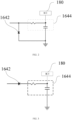
- 100 aerosol generating device 120 shell, 122 atomization cavity, 140 microwave assembly, 160 voltage acquisition assembly, 162 feed point, 164 filter assembly, 1642 diode, 1644 filter circuit, 180 controller.
- An aerosol generating device, a control method of the aerosol generating device, a control device of the aerosol generating device and a readable storage medium in some embodiments of the present disclosure will be described below with reference to FIG. 1 to FIG. 9 .
- an aerosol generating device 100 is provided in the first embodiment of the present disclosure, comprising: a shell 120, an atomization cavity 122, a microwave assembly 140, a voltage acquisition assembly 160, and a controller 180.
- An atomization cavity 122 is arranged in the shell 120.
- the microwave assembly 140 is connected to the shell 120 and configured to feed a microwave into the atomization cavity 122.
- the voltage acquisition assembly 160 is arranged in the atomization cavity 122 and configured to acquire the feedback voltage values of the atomization cavity 122.
- the controller 180 is connected to the voltage acquisition assembly 160 and configured to determine the target operating frequency of the microwave assembly 140 according to the feedback voltage value.
- the aerosol generating device 100 provided in the present embodiment comprises a shell 120, a microwave assembly 140, a voltage acquisition assembly 160, and a controller 180.
- An atomization cavity 122 is arranged in the shell 120, and an aerosol-generating substrate can be accommodated in the atomization cavity 122.
- the microwave assembly 140 is installed on the shell 120, and the microwave assembly 140 can feed a microwave into the atomization cavity 122.
- the aerosol-generating substrate accommodated in the atomization cavity 122 can be heated and atomized under the action of microwaves fed by the microwave assembly 140.
- the microwave generated by the microwave assembly 140 will generate current in the wall structure of the atomization cavity 122 due to the resonance characteristics of the atomization cavity 122.
- the feedback voltage value of the current on the wall structure of the atomization cavity 122 can be acquired by the voltage acquisition assembly 160, the voltage acquisition assembly transmits the feedback voltage value to the controller 180, and the controller 180 can judge the energy at the wall of the atomization cavity 122 according to the feedback voltage value.
- the voltage acquisition assembly 160 continuously acquires the feedback voltage values on the cavity wall of the atomization cavity 122, and the controller 180 records the acquired feedback voltage values after the frequency sweeping operation of the microwave assembly.
- the controller 180 compares the sizes of multiple feedback voltage values, and takes the operating frequency corresponding to the largest feedback voltage value among the plurality of feedback voltage value as the target operating frequency. Understandably, if the feedback voltage value is large, it means that the microwave with the current frequency feeds more energy into the atomization cavity 122, so the operating frequency corresponding to the maximum feedback voltage value is the resonance frequency of the atomization cavity 122. Therefore, controlling the microwave assembly 140 to operate according to the operating frequency corresponding to the maximum feedback voltage value can make the microwave assembly 140 operate at the optimal frequency point, and improve the heating and atomization efficiency of the aerosol generating device 100 on the aerosol-generating substrate.
- the microwave-generating assembly is controlled to conduct the frequency sweeping operation within the set frequency range, and the minimum frequency of the set frequency range is 2.2G, and the maximum frequency is 2.57G.
- the microwave assembly 140 starts operating from the minimum frequency, and the microwave assembly 140 is controlled to increase by 10MHz every 2 ms until the maximum frequency is reached. Every time when the operating frequency is switched, a feedback voltage value will be recorded. After the frequency sweeping is completed, the operating frequency corresponding to the maximum value of the feedback voltage is taken as the target operating frequency, and the microwave assembly 140 is controlled to feed a microwave into the atomization cavity 122 according to the target operating frequency.
- a circulator for detecting the standing-wave ratio is always arranged in the aerosol generating device, which takes up a large space in the aerosol generating device, generates heat during the operation of the circulator and thus results in a decrease in the efficiency of the whole system.
- the voltage acquisition assembly 160 capable of acquiring the feedback voltage values at the cavity wall of the atomization cavity 122 is arranged in the atomization cavity 122, so that the controller 180 can determine the currently fed energy in the atomization cavity 122 according to the feedback voltage value and determine the resonance frequency of the atomization cavity 122. That is, the optimal frequency point for the operation of the microwave assembly 140. Controlling the atomization assembly according to the optimal frequency point can improve the heating atomization efficiency of the aerosol generating device 100 on the aerosol-generating substrate.
- the present disclosure can ensure the accuracy and detection efficiency of the detected optimal frequency point of the microwave assembly 140, and there is no need to additionally arrange a large circulator in the atomization cavity 122. This is beneficial to the miniaturization of products and helps reduce the production cost.
- the voltage acquisition assembly 160 will not generate lots of heat during the operation, which ensures the operation efficiency of the aerosol generating device 100.
- aerosol generating device 100 in the above technical solutions provided in this embodiment may have the following additional technical features:
- the voltage acquisition assembly 160 comprises: a feed point 162 and a filter assembly 164.
- the feed point 162 is arranged on the inner wall of the shell 120;
- the first end of the filter assembly 164 is connected to the feed point 162, and the second end of the filter assembly 164 is connected to the controller 180.
- the voltage acquisition assembly 160 comprises a feed point 162 and a filter assembly 164.
- a feed point 162 is arranged on the inner wall of the shell 120. That is, a feed point 162 is arranged in the inner cavity of the atomization cavity 122.
- the voltage signal at the inner side wall of the atomization cavity 122 is acquired through the feed point 162, and the voltage signal is filtered by the filter assembly 164 and transmitted to the controller 180, so that the controller 180 can acquire the feedback voltage values at the atomization cavity 122 through the feed point 162.
- the feed point 162 is arranged in the atomization cavity 122, so that the feedback voltage values at the cavity wall of the atomization cavity 122 are acquired.
- the filter assembly 164 comprises: a diode 1642 and a filter circuit 1644.
- the first end of the diode 1642 is connected to the feed point 162, and the second end of the diode 1642 is grounded.
- the first end of the filter circuit 1644 is connected to the first end of the diode 1642, the second end of the filter assembly 164 is connected to the second end of the diode 1642, and the filter circuit 1644 is connected to the controller 180. wherein, the second end of the diode 1642 is conducted to the first end.
- the filter assembly 164 comprises a diode 1642 and a filter circuit 1644.
- the diode 1642 is a rectifier diode 1642, and the current at the inner wall of the atomization cavity 122 is rectified into a DC signal.
- the DC signal is filtered by the filter circuit 1644, and the filtered DC signal is transmitted to the controller 180.
- the filtered DC signal received by the controller 180 can determine the feedback voltage value at the chamber wall of the atomization cavity 122.
- the diode 1642 is connected in parallel to the filter circuit 1644.
- the first end of the diode 1642 is the cathode of the diode 1642, the cathode of the diode is connected to the feed point 162, the anode of the diode 1642 is connected to the ground terminal, and the controller 180 is connected to the rectifier circuit.
- the feedback voltage values of the negative current on the cavity wall of the atomization cavity 122 can be acquired through the cathode of the diode 1642.
- the diode 1642 is arranged in parallel with the filter circuit 1644, and the cathode of the diode 1642 is connected to the feed point 162, so that the filter assembly 164 can acquire the feedback voltage values of the negative current on the cavity wall of the atomization cavity 122 through the feed point 162.
- the filter assembly 164 comprises: a diode 1642 and a filter circuit 1644.
- the first end of the diode 1642 is connected to the feed point 162.
- the first end of the filter circuit 1644 is connected to the second end of the diode 1642, and the second end of the filter circuit 1644 is grounded, and the filter circuit 1644 is connected to the controller 180.
- the first end to the second end of the diode 1642 is conductive.
- the filter assembly 164 comprises a diode 1642 and a filter circuit 1644.
- the diode 1642 is a rectifier diode 1642, and the current at the inner wall of the atomization cavity 122 is rectified into a DC signal.
- the DC signal is filtered by the filter circuit 1644, and the filtered DC signal is transmitted to the controller 180.
- the filtered DC signal received by the controller 180 can determine the feedback voltage value at the chamber wall of the atomization cavity 122.
- the diode 1642 is connected in series to a filter circuit 1644.
- the first end of the diode 1642 is the anode of the diode 1642, the anode of the diode 1642 is connected to the feed point 162, and the cathode of the diode 1642 is connected to the controller 180 through the rectifier circuit.
- the feedback voltage values of the forward current on the cavity wall of the atomization cavity 122 can be acquired through the anode of the diode 1642.
- the diode 1642 is arranged in series with the filter circuit 1644, and the anode of the diode 1642 is connected to the feed point 162, so that the filter assembly 164 can acquire the feedback voltage values of the forward current on the cavity wall of the atomization cavity 122 through the feed point 162.
- the filter circuit 1644 comprises any one or a combination of the following: capacitor filter circuit 1644, resistance capacitor filter circuit 1644, and inductance capacitor filter circuit 1644.
- the filter circuit 1644 is selected as a DC filter circuit 1644. Specifically, it can be any one or a combination of capacitor filter circuit 1644, resistor-capacitor filter circuit 1644 (RC) and inductor-capacitor filter circuit 1644 (LC).
- the filter circuit 1644 is selected as an inductor-capacitor filter circuit 1644, and the diode 1642 is connected in series to the inductor-capacitor filter circuit 1644.
- the first end of the diode 1642 is connected to the feed point 162
- the second end of the diode 1642 is connected in series to the inductor and capacitor
- the capacitor is connected to the controller 180
- the capacitor and the common terminal of the controller 180 are grounded.
- the diode 1642 is conducted from the first end to the second end.
- the current at the cavity wall of the atomization cavity 122 is rectified by the diode 1642 to become a direct current signal
- the direct current signal is filtered by the inductor-capacitor filter circuit 1644 and then transmitted to the controller 180, and the controller 180 can obtain a feedback voltage value by processing the direct current signal.
- the feed point 162 comprises:
- the feed point 162 can be optionally set in various forms, comprising but not limited to through hole, conducting ring and lead.
- the feed point 162 is set as a through hole, and the through hole is set at the bottom wall of the atomization cavity 122, and the sampling end of the filter assembly 164 is connected to the hole wall of the through hole to acquire the feedback voltage values at the hole wall position of the bottom wall of the atomization cavity 122.
- the feed point 162 is set as a conducting ring, and the conducting ring can be specifically selected as a copper ring.
- the conducting ring is arranged on the inner side wall of the atomization cavity 122 and near the bottom wall of the atomization cavity 122.
- the sampling end of the filter assembly 164 is connected to the conducting ring, the conducting ring is arranged at the cavity wall of the atomization cavity 122, and the conducting ring can lead the current at the cavity wall to the filter assembly 164, so that the feedback voltage values at the cavity wall of the atomization cavity 122 can be acquired through the conducting ring.
- a control method of the aerosol generating device is provided in the second embodiment of the present disclosure.
- the aerosol generating device comprises a microwave assembly, an atomization cavity and a voltage acquisition assembly.
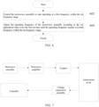
- the control method of the aerosol generating device comprises the following steps:
- step 408 and control the microwave assembly to operate according to the target frequency.
- the control method of the aerosol generating device controls the aerosol generating device.
- the aerosol generating device comprises a shell, a microwave assembly, a voltage acquisition assembly, and a controller.
- An atomization cavity is arranged in the shell, and an aerosol-generating substrate can be accommodated in the atomization cavity.
- the microwave assembly is installed on the shell, and the microwave assembly can feed a microwave into the atomization cavity.
- the aerosol-generating substrate accommodated in the atomization cavity can be heated and atomized under the action of microwaves fed by the microwave assembly.
- the microwave generated by the microwave assembly will generate current in the wall structure of the atomization cavity due to the resonance characteristics of the atomization cavity.
- the microwave assembly When the aerosol-generating substrate is located in the atomization cavity, the microwave assembly is controlled to start frequency sweeping operation within the set frequency range.
- multiple feedback voltage values at the cavity wall of the atomization cavity are continuously acquired by the voltage acquisition assembly. Understandably, multiple feedback voltage values correspond to multiple operating frequencies in the process of frequency sweeping operation of the microwave component.
- the target frequency within the set frequency range can be obtained.
- the microwave assembly is controlled to feed a microwave into the atomization cavity according to the target frequency, so as to heat and atomize the aerosol-generating substrate in the atomization cavity.
- the target frequency is the operating frequency closest to the resonance frequency of the cavity in the RF frequency range. That is, the optimal frequency point during the operation of the microwave assembly. Controlling the aerosol generating device to feed a microwave into the atomization cavity according to the target frequency can improve the atomization efficiency of the aerosol-generating substrate in the atomization cavity.
- a circulator for detecting the standing-wave ratio is always arranged in the aerosol generating device, which takes up a large space in the aerosol generating device, generates heat during the operation of the circulator and thus results in a decrease in the efficiency of the whole system.
- the voltage acquisition assembly capable of acquiring the feedback voltage values at the cavity wall of the atomization cavity is arranged in the atomization cavity, so that the controller can determine the currently fed energy in the atomization cavity according to the feedback voltage value and determine the resonance frequency of the atomization cavity. That is, the optimal frequency point for the operation of the microwave assembly. Controlling the atomization assembly according to the optimal frequency point can improve the heating atomization efficiency of the aerosol generating device on the aerosol-generating substrate.
- the present disclosure can ensure the accuracy and detection efficiency of the detected optimal frequency point of the microwave assembly, and there is no need to additionally arrange a circulator with a large volume in the atomization cavity. This is beneficial to the miniaturization of products and helps reduce the production cost.
- the voltage acquisition assembly will not generate lots of heat during the operation process, which ensures the operation efficiency of the aerosol generating device.
- the target frequency within the set frequency range is determined according to the feedback voltage value, which further comprises:
- the voltage acquisition assembly continuously acquires the feedback voltage values on the wall of the atomization cavity, and the controller records the acquired feedback voltage values after the frequency sweeping operation of the microwave assembly.
- the controller compares the sizes of multiple feedback voltage values, and takes the operating frequency corresponding to the largest feedback voltage value among the multiple feedback voltage values as the target operating frequency.
- the microwave assembly can make the microwave assembly operate at the optimal frequency point, and improve the heating atomization efficiency of the aerosol generating device on the aerosol-generating substrate.
- the steps for controlling the microwave assembly to conduct the frequency sweeping operation within the set frequency range comprises:
- control the microwave assembly to conduct the frequency sweeping operation within the set frequency range. Specifically, control the microwave assembly to start operating at a lower first frequency within the set frequency range, and control the microwave assembly to adjust the operating frequency to a set adjustment value every the first set time until it is adjusted to a second frequency within the set frequency range.
- the first frequency is greater than the second frequency, or the first frequency is less than the second frequency. That is, the microwave assembly can operate from low to high frequency within the set frequency range, or from high to low frequency within the set frequency range.
- the microwave-generating assembly is controlled to conduct the frequency sweeping operation within the set frequency range, and the minimum frequency of the set frequency range is 2.2G, and the maximum frequency is 2.57G.
- the microwave assembly starts operating from the minimum frequency, and the microwave assembly is controlled to increase by 10MHz every 2ms until the maximum frequency is reached. Every time when the operating frequency is switched, a feedback voltage value will be recorded. After the frequency sweeping is completed, the operating frequency corresponding to the maximum value of the feedback voltage is taken as the target operating frequency, and the microwave assembly is controlled to feed a microwave into the atomization cavity according to the target operating frequency.
- the operating frequency of the microwave assembly is controlled to adjust the set adjustment value every the first set time, so that there is enough time for the microwave assembly to feed a microwave into the atomization cavity at every operating frequency, the correspondence between multiple feedback voltage values and multiple operating frequencies within the set frequency range is improved, and the accuracy of obtaining the target frequency is further improved.
- the steps for acquiring multiple feedback voltage values of the atomization cavity through the voltage acquisition assembly when the microwave assembly is under the frequency sweeping operation comprises: acquire the feedback voltage values of the atomization cavity every the first set time when the microwave assembly is in the operation state.
- the feedback voltage value of the atomization cavity is acquired every the first set time in the process of frequency sweeping operation.
- the acquired multiple feedback voltage values can be matched with the operating frequencies within the set frequency range, which is convenient for finding the accurate target frequency according to the maximum voltage value among the multiple feedback voltage values.
- the voltage acquisition assembly continuously detects the feedback voltage value of the atomization cavity, and records the current feedback voltage value every the first set time.
- the voltage acquisition assembly detects and records the current feedback voltage value every the first set time.
- the steps for controlling the microwave assembly to operate according to the target frequency further comprises: return to the step of controlling the microwave assembly to operate within the set frequency range until the stop instruction is received when the microwave assembly is operated at the target frequency for a second set time.
- control the microwave assembly to operate for a second set time according to the target frequency, and then return the step of controlling the microwave assembly to sweep the frequency to search the target frequency again.
- the aerosol-generating substrate in the aerosol generating device is heated and atomized along with the operation of the microwave assembly, the aerosol-generating substrate in the atomization cavity changes, and the resonance frequency of the atomization cavity changes as well.
- the microwave assembly in the aerosol generating device can work at the optimal frequency point for a long time, and the atomization effect of the aerosol generating device on the aerosol-generating substrate is improved.
- the operation of microwave assembly is controlled by the closed-loop control of feedback voltage value.
- the controller acquires the feedback voltage values of the cavity, and the target frequency is determined according to the feedback voltage value.
- the microwave assembly is controlled to operate according to the target frequency.
- the microwave is fed into the atomization cavity after passing through the microwave amplifier and coupler.
- a control device 800 of the aerosol generating device is provided in the third embodiment of the present disclosure, wherein the aerosol generating device comprises a microwave assembly, an atomization cavity and a voltage acquisition assembly.
- the control device of the aerosol generating device comprises:
- the microwave assembly When the aerosol-generating substrate is located in the atomization cavity, the microwave assembly is controlled to start frequency sweeping operation within the set frequency range.
- multiple feedback voltage values at the cavity wall of the atomization cavity are continuously acquired by the voltage acquisition assembly. Understandably, multiple feedback voltage values correspond to multiple operating frequencies in the process of frequency sweeping operation of the microwave component.
- the target frequency within the set frequency range can be obtained.
- the microwave assembly is controlled to feed a microwave into the atomization cavity according to the target frequency, so as to heat and atomize the aerosol-generating substrate in the atomization cavity.
- the target frequency is the operating frequency closest to the resonance frequency of the cavity in the RF frequency range. That is, the optimal frequency point during the operation of the microwave assembly. Controlling the aerosol generating device to feed a microwave into the atomization cavity according to the target frequency can improve the atomization efficiency of the aerosol-generating substrate in the atomization cavity.
- a circulator for detecting the standing-wave ratio is always arranged in the aerosol generating device, which takes up a large space in the aerosol generating device, generates heat during the operation of the circulator and thus results in a decrease in the efficiency of the whole system.
- the voltage acquisition assembly capable of acquiring the feedback voltage values at the cavity wall of the atomization cavity is arranged in the atomization cavity, so that the controller can determine the currently fed energy in the atomization cavity according to the feedback voltage value and determine the resonance frequency of the atomization cavity. That is, the optimal frequency point for the operation of the microwave assembly. Controlling the atomization assembly according to the optimal frequency point can improve the heating atomization efficiency of the aerosol generating device on the aerosol-generating substrate.
- the present disclosure can ensure the accuracy and detection efficiency of the detected optimal frequency point of the microwave assembly, and there is no need to additionally arrange a circulator with a large volume in the atomization cavity. This is beneficial to the miniaturization of products and helps reduce the production cost.
- the voltage acquisition assembly will not generate lots of heat during the operation process, which ensures the operation efficiency of the aerosol generating device.
- a control device of the aerosol generating device further comprises:
- the voltage acquisition assembly continuously acquires the feedback voltage values on the wall of the atomization cavity, and the controller records the acquired feedback voltage values after the frequency sweeping operation of the microwave assembly.
- the controller compares the sizes of multiple feedback voltage values, and takes the operating frequency corresponding to the largest feedback voltage value among the multiple feedback voltage values as the target operating frequency.
- control module 802 is further configured to control the microwave assembly to start operating at a first frequency within the set frequency range.
- the control module 802 is further configured to adjust the operating frequency of the microwave assembly according to the set adjustment value every the first set time until the operating frequency reaches a second frequency within the set frequency range.
- control the microwave assembly to conduct the frequency sweeping operation within the set frequency range. Specifically, control the microwave assembly to start operating at a lower first frequency within the set frequency range, and control the microwave assembly to adjust the operating frequency to a set adjustment value every the first set time until it is adjusted to a second frequency within the set frequency range.
- the first frequency is greater than the second frequency, or the first frequency is less than the second frequency. That is, the microwave assembly can operate from low to high frequency within the set frequency range, or from high to low frequency within the set frequency range.
- the microwave-generating assembly is controlled to conduct the frequency sweeping operation within the set frequency range, and the minimum frequency of the set frequency range is 2.2G, and the maximum frequency is 2.57G.
- the microwave assembly starts operating from the minimum frequency, and the microwave assembly is controlled to increase by 10MHz every 2ms until the maximum frequency is reached. Every time when the operating frequency is switched, a feedback voltage value will be recorded. After the frequency sweeping is completed, the operating frequency corresponding to the maximum value of the feedback voltage is taken as the target operating frequency, and the microwave assembly is controlled to feed a microwave into the atomization cavity according to the target operating frequency.
- the operating frequency of the microwave assembly is controlled to adjust the set adjustment value every the first set time, so that there is enough time for the microwave assembly to feed a microwave into the atomization cavity at every operating frequency, the correspondence between multiple feedback voltage values and multiple operating frequencies within the set frequency range is improved, and the accuracy of obtaining the target frequency is further improved.
- the acquisition module 804 is further configured to acquire the feedback voltage values of the atomization cavity every the first set time when the microwave assembly is in operation.
- the feedback voltage value of the atomization cavity is acquired every the first set time in the process of frequency sweeping operation.
- the acquired multiple feedback voltage values can be matched with the operating frequencies within the set frequency range, which is convenient for finding the accurate target frequency according to the maximum voltage value among the multiple feedback voltage values.
- control module 802 is further configured to return to the step of controlling the microwave assembly to operate within the set frequency range until the stop instruction is received hen the microwave assembly is operated at the target frequency for a second set time.
- control the microwave assembly to operate for a second set time according to the target frequency, and then return the step of controlling the microwave assembly to sweep the frequency to search the target frequency again.
- the aerosol-generating substrate in the aerosol generating device is heated and atomized along with the operation of the microwave assembly, the aerosol-generating substrate in the atomization cavity changes, and the resonance frequency of the atomization cavity changes as well.
- the microwave assembly in the aerosol generating device can work at the optimal frequency point for a long time, and the atomization effect of the aerosol generating device on the aerosol-generating substrate is improved.
- a control device 900 of the aerosol generating device is provided in the fourth embodiment of the present disclosure, comprising: a memory 902 storing programs or instructions; and a processor 904 executing the programs or instructions stored in the memory 902 to realize the steps for the control method of the aerosol generating device in any of the above embodiments. Therefore, it has all the beneficial technical effects of the control method of the aerosol generating device in any of the above embodiments. It will not be explained in detail.
- a readable storage medium is provided in the fifth aspect of the present disclosure, on which programs are stored.
- the control method of the aerosol generating device in any of the above embodiments is realized. Therefore, it has all the beneficial technical effects of the control method of the aerosol generating device in any of the above embodiments.
- readable storage medium such as Read-Only Memory (ROM), Random Access Memory (RAM), magnetic disk or compact disc, etc.
- An aerosol generating device is provided in the sixth embodiment of the present disclosure, comprising: a control device of the aerosol generating device in the third and/or fourth embodiment, and/or a readable storage medium in the fifth embodiment. Therefore, it has all the beneficial technical effects of the control device of the aerosol generating device and/or the readable storage medium. It will not be explained in detail.
- the aerosol generating device further comprises an atomization cavity, a microwave-generating device, a controller and a voltage acquisition device.
- the controller acquires the feedback voltage values of the cavity, and the target frequency is determined according to the feedback voltage value.
- the microwave assembly is controlled to operate according to the target frequency.
- the microwave is fed into the atomization cavity after passing through the microwave amplifier and coupler.
- connection may be a fixed connection between multiple objects, a detachable connection between multiple objects, or an integral connection; or may be a direct connection between multiple objects, or an indirect connection between multiple objects through an intermediate medium.
- connection may be a fixed connection between multiple objects, a detachable connection between multiple objects, or an integral connection; or may be a direct connection between multiple objects, or an indirect connection between multiple objects through an intermediate medium.
- the terms “one embodiment”, “some embodiments”, “specific embodiments”, etc. mean that the specific features, structures, materials, or characteristics described in conjunction with the embodiments or examples are included in at least one embodiment or example of the present disclosure.
- the illustrative expressions of the above terms may not necessarily refer to the same embodiment or example.
- the particular features, structures, materials, or characteristics described may be combined in an appropriate manner in any one or more embodiments or examples.
Landscapes
- Physics & Mathematics (AREA)
- Electromagnetism (AREA)
- Electrostatic Spraying Apparatus (AREA)
Abstract
Description
- The present disclosure is required to be submitted to China National Intellectual Property Administration on December 9, 2021, with the present disclosure number "202111498340.8" and the title "aerosol generating device, control method thereof, control device and readable storage medium". The priority and entire contents of this Chinese patent application are incorporated in the present disclosure by reference.
- The present disclosure relates to the field of electronic cigarette, and more specifically, to an aerosol generating device, control method thereof, control device and readable storage medium.
- A heat-not-burn (HNB) device is a combination of heating device and aerosol-generating substrate (a processed plant leaf product). The external heating device can heat the aerosol-generating substrate to a high temperature at which the aerosol-generating substrate can generate aerosol but does not burn, so that the aerosol-generating substrate can generate the aerosol required a user on the premise of not burning.
- Currently, the HNB device in the market mainly adopts a resistance heating mode, which uses a central heating sheet or a central heating needle or the like to insert into the aerosol-forming substrate for heating. This device needs a long preheating waiting time before use, and cannot be smoked and stopped freely. The carbonization of the aerosol-forming substrate is uneven, resulting in insufficient baking and a low utilization rate of the aerosol-forming substrate. Secondly, the heating sheet of the HNB device is prone to generating dirt in the aerosol-forming substrate extractor and the heating sheet base, making it difficult to clean. Besides, the local aerosol-forming substrate in contact with the heating sheet is too high in temperature, leading to a partial cracking to produce harmful substances to the human body. Therefore, the microwave heating technology gradually replaces the resistance heating mode to become a new heating mode. The microwave heating technology has the characteristics of high efficiency, timeliness, selectivity, and no delay in heating, and only has a heating effect on substances having specific dielectric properties. The advantages of using the microwave heating for atomization are as follows: a. the microwave heating is radiation heating and non-heat conduction, and instant smoking and stopping can be achieved; b. no heating sheet exists, so that the problems of sheet breaking and heating sheet cleaning do not exist; c. the aerosol-forming substrate is high in utilization rate, high in taste consistency, and closer to a cigarette in taste.
- In the prior art, the aerosol generating device always determines the optimal frequency point of the microwave assembly by detecting the standing-wave ratio through the circulator. The miniaturization design of the aerosol generating device cannot be satisfied due to the large volume of the circulator.
- The present disclosure aims to solve one of the technical problems existing in the prior art or related technologies.
- Therefore, an aerosol generating device is provided in the first aspect of the present disclosure.
- A control method of the aerosol generating device is provided in the second aspect of the present disclosure.
- A control device of the aerosol generating device is provided in the third aspect of the present disclosure.
- A control device of the aerosol generating device is provided in the fourth aspect of the present disclosure.
- A readable storage medium is provided in the fifth aspect of the present disclosure.
- An aerosol generating device is provided in the sixth aspect of the present disclosure.
- In view of this, an aerosol generating device is provided in the first aspect of the present disclosure, comprising: a shell comprising an atomization cavity; a microwave assembly connected to the shell and configured to feed a microwave into the atomization cavity; a voltage acquisition assembly arranged in the atomization cavity and configured to acquire the feedback voltage values of the atomization cavity; and a controller connected to the voltage acquisition assembly and configured to determine the target operating frequency of the microwave assembly according to the feedback voltage value.
- The aerosol generating device provided in the present disclosure comprises a shell, a microwave assembly, a voltage acquisition assembly, and a controller. An atomization cavity is arranged in the shell, and an aerosol-generating substrate can be accommodated in the atomization cavity. The microwave assembly is installed on the shell, and the microwave assembly can feed a microwave into the atomization cavity. The aerosol-generating substrate accommodated in the atomization cavity can be heated and atomized under the action of microwaves fed by the microwave assembly. The microwave generated by the microwave assembly generates current in the wall structure of the atomization cavity due to the resonance characteristics of the atomization cavity. The feedback voltage value of the current on the wall structure of the atomization cavity can be acquired by the voltage acquisition assembly, the voltage acquisition assembly transmits the feedback voltage value to the controller, and the controller can judge the energy at the wall of the atomization cavity according to the feedback voltage value.
- Specifically, during the frequency sweeping operation of the microwave assembly, the voltage acquisition assembly continuously acquires the feedback voltage values on the wall of the atomization cavity, and the controller records the acquired feedback voltage values after the frequency sweeping operation of the microwave assembly. The controller compares the sizes of multiple feedback voltage values, and takes the operating frequency corresponding to the largest feedback voltage value among the multiple feedback voltage values as the target operating frequency. Understandably, if the feedback voltage value is large, it means that the microwave with the current frequency feeds more energy into the atomization cavity, so the operating frequency corresponding to the maximum feedback voltage value is the resonance frequency of the atomization cavity. Therefore, controlling the microwave assembly to operate according to the operating frequency corresponding to the maximum feedback voltage value can make the microwave assembly operate at the optimal frequency point, and improve the heating atomization efficiency of the aerosol generating device on the aerosol-generating substrate.
- For example, the microwave-generating assembly is controlled to conduct the frequency sweeping operation within the set frequency range, and the minimum frequency of the set frequency range is 2.2G, and the maximum frequency is 2.57G. In the process of frequency sweeping operation, the microwave assembly starts operating from the minimum frequency, and the microwave assembly is controlled to increase by 10MHz every 2ms until the maximum frequency is reached. Every time when the operating frequency is switched, a feedback voltage value will be recorded. After the frequency sweeping is completed, the operating frequency corresponding to the maximum value of the feedback voltage is taken as the target operating frequency, and the microwave assembly is controlled to feed a microwave into the atomization cavity according to the target operating frequency.
- In the related technologies, a circulator for detecting the standing-wave ratio is always arranged in the aerosol generating device, which takes up a large space in the aerosol generating device, generates heat during the operation of the circulator and thus results in a decrease in the efficiency of the whole system.
- In the present disclosure, the voltage acquisition assembly capable of acquiring the feedback voltage values at the cavity wall of the atomization cavity is arranged in the atomization cavity, so that the controller can determine the currently fed energy in the atomization cavity according to the feedback voltage value and determine the resonance frequency of the atomization cavity. That is, the optimal frequency point for the operation of the microwave assembly. Controlling the atomization assembly according to the optimal frequency point can improve the heating atomization efficiency of the aerosol generating device on the aerosol-generating substrate. The present disclosure can ensure the accuracy and detection efficiency of the detected optimal frequency point of the microwave assembly, and there is no need to additionally arrange a circulator with a large volume in the atomization cavity. This is beneficial to the miniaturization of products and helps reduce the production cost. Moreover, the voltage acquisition assembly will not generate lots of heat during the operation process, which ensures the operation efficiency of the aerosol generating device.
- Further, the aerosol generating device in the above technical solution provided in the present disclosure may have the following additional technical features:
- In one possible design, the voltage acquisition assembly comprises: a feed point arranged on the inner wall of the shell; and a filter assembly. The first end of the filter assembly is connected to the feed point, and the second end of the filter assembly is connected to the controller.
- In this design, the voltage acquisition assembly comprises a feed point and a filter assembly. A feed point is arranged on the inner wall of the shell. That is, a feed point is arranged in the inner cavity of the atomization cavity. The voltage signal at the inner side wall of the atomization cavity is acquired through the feed point, and the voltage signal is filtered by the filter assembly and transmitted to the controller, so that the controller can acquire the feedback voltage values at the atomization cavity through the feed point.
- When a microwave is fed into the atomization cavity, due to the resonance characteristics of the atomization cavity, current will be generated in the cavity wall structure of the atomization cavity. In the present disclosure, the feed point is arranged in the atomization cavity, so that the feedback voltage values at the cavity wall of the atomization cavity are acquired.
- In one possible design, the filter assembly comprises: a diode, the first end of the diode is connected to the feed point, and the second end of the diode is grounded; a filter circuit, the first end of the filter circuit is connected to the first end of the diode, the second end of the filter assembly is connected to the second end of the diode, and the filter circuit is connected to the controller; wherein, the second end of the diode is conducted to the first end.
- In this design, the filter assembly comprises a diode and a filter circuit. The diode is a rectifier diode, and the current at the inner wall of the atomization cavity is rectified into a DC signal. The DC signal is filtered by the filter circuit, and the filtered DC signal is transmitted to the controller. The filtered DC signal received by the controller can determine the feedback voltage value at the cavity wall of the atomization cavity.
- Specifically, the diode is connected in parallel to the filter circuit. The first end of the diode is the cathode of the diode, the cathode of the diode is connected to the feed point, the anode of the diode is connected to the grounding terminal, and the controller is connected to the rectifier circuit. The feedback voltage values of the negative current on the cavity wall of the atomization cavity can be acquired through the cathode of the diode.
- In the present disclosure, the diode is arranged in parallel with the filter circuit, and the cathode of the diode is connected to the feed point, so that the filter assembly can acquire the feedback voltage values of the negative current on the cavity wall of the atomization cavity through the feed point.
- In one possible design, the filter assembly comprises a diode, the first end of the diode is connected to the feed point; a filter circuit, the first end of the filter circuit is connected to the second end of the diode, the second end of the filter circuit is grounded, and the filter circuit is connected to the controller; wherein, the first end of the diode is conducted to the second end.
- In this design, the filter assembly comprises a diode and a filter circuit. The diode is a rectifier diode, and the current at the inner wall of the atomization cavity is rectified into a DC signal. The DC signal is filtered by the filter circuit, and the filtered DC signal is transmitted to the controller. The filtered DC signal received by the controller can determine the feedback voltage value at the cavity wall of the atomization cavity.
- Specifically, the diode is connected in series to the filter circuit. The first end of the diode is the anode of the diode, the anode of the diode is connected to the feed point, and the cathode of the diode is connected to the controller through the rectifier circuit. The feedback voltage values of the forward current on the cavity wall of the atomization cavity can be acquired through the anode of the diode.
- In the present disclosure, the diode is arranged in series with the filter circuit, and the anode of the diode is connected to the feed point, so that the filter assembly can acquire the feedback voltage values of the forward current on the cavity wall of the atomization cavity through the feed point.
- In a possible design, the filter circuit comprises any one or a combination of the following: capacitor filter circuit, resistor-capacitor filter circuit, and inductor-capacitor filter circuit.
- In this design, the filter circuit is selected as a DC filter circuit. Specifically, it can be any one or a combination of capacitor filter circuit, resistor-capacitor filter circuit (RC), and inductor-capacitor filter circuit (LC).
- In some embodiments, the filter circuit is selected as an inductor-capacitor filter circuit, and the diode is connected in series to the inductor-capacitor filter circuit.
- In these embodiments, the first end of the diode is connected to the feed point, the second end of the diode is connected in series to the inductor and capacitor, the capacitor is connected to the controller, and the capacitor and the common terminal of the controller are grounded. The diode is conducted from the first end to the second end. The current at the cavity wall of the atomization cavity is rectified by the diode to become a direct current signal, the direct current signal is filtered by the inductor-capacitor filter circuit and then transmitted to the controller, and the controller can obtain a feedback voltage value by processing the direct current signal.
- In one possible design, the feed point comprises: a through hole arranged on the bottom wall of the atomization cavity, and the filter assembly connected to the hole wall of the through hole; or a conducting ring arranged on the inner wall of the atomization cavity, the conducting ring close to the bottom wall of the atomization cavity, and the filter assembly connected to the conducting ring; or a lead, the first end of the lead connected to the bottom wall of the atomization cavity, and the second end of the lead connected to the filter assembly.
- In this design, the feed point can be optionally set in various forms, comprising but not limited to through hole, conducting ring and lead.
- In some embodiments, the feed point is set as a through hole, and the through hole is set at the bottom wall of the atomization cavity, and the sampling end of the filter assembly is connected to the hole wall of the through hole to acquire the feedback voltage values at the hole wall position of the bottom wall of the atomization cavity.
- In some other embodiments, the feed point is set as a conducting ring, and the conducting ring can be specifically selected as a copper ring. The conducting ring is arranged on the inner side wall of the atomization cavity and near the bottom wall of the atomization cavity. The sampling end of the filter assembly is connected to the conducting ring, the conducting ring is arranged at the cavity wall of the atomization cavity, and the conducting ring can lead the current at the cavity wall to the filter assembly, so that the feedback voltage values at the cavity wall of the atomization cavity can be acquired through the conducting ring.
- A control method of the aerosol generating device is provided in the second aspect of the present disclosure. The aerosol generating device comprises a microwave assembly, an atomization cavity and a voltage acquisition assembly. The control method of the aerosol generating device comprises the following steps: control the microwave assembly to conduct the frequency sweeping operation within the set frequency range; acquire multiple feedback voltage values of the atomization cavity through the voltage acquisition assembly when the microwave assembly is under the frequency sweeping operation; determine a target frequency within the set frequency range according to multiple feedback voltage values; and control the microwave assembly to operate according to the target frequency.
- The control method of the aerosol generating device provided in the present disclosure controls the aerosol generating device. The aerosol generating device comprises a shell, a microwave assembly, a voltage acquisition assembly, and a controller. An atomization cavity is arranged in the shell, and an aerosol-generating substrate can be accommodated in the atomization cavity. The microwave assembly is installed on the shell, and the microwave assembly can feed a microwave into the atomization cavity. The aerosol-generating substrate accommodated in the atomization cavity can be heated and atomized under the action of microwaves fed by the microwave assembly. The microwave generated by the microwave assembly will generate current in the wall structure of the atomization cavity due to the resonance characteristics of the atomization cavity.
- When the aerosol-generating substrate is located in the atomization cavity, the microwave assembly is controlled to start frequency sweeping operation within the set frequency range. In the process of frequency sweeping operation of the microwave assembly, multiple feedback voltage values at the cavity wall of the atomization cavity are continuously acquired by the voltage acquisition assembly. Understandably, multiple feedback voltage values correspond to multiple operating frequencies in the process of frequency sweeping operation of the microwave component. By analyzing and processing multiple feedback voltage values, the target frequency within the set frequency range can be obtained. The microwave assembly is controlled to feed a microwave into the atomization cavity according to the target frequency, so as to heat and atomize the aerosol-generating substrate in the atomization cavity.
- Understandably, by acquiring the feedback voltage values in the frequency sweeping process and determining the target frequency according to the feedback voltage value, the target frequency is the operating frequency closest to the resonance frequency of the cavity in the RF frequency range. That is, the optimal frequency point during the operation of the microwave assembly. Controlling the aerosol generating device to feed a microwave into the atomization cavity according to the target frequency can improve the atomization efficiency of the aerosol-generating substrate in the atomization cavity.
- In the related technologies, a circulator for detecting the standing-wave ratio is always arranged in the aerosol generating device, which takes up a large space in the aerosol generating device, generates heat during the operation of the circulator and thus results in a decrease in the efficiency of the whole system.
- In the present disclosure, the voltage acquisition assembly capable of acquiring the feedback voltage values at the cavity wall of the atomization cavity is arranged in the atomization cavity, so that the controller can determine the currently fed energy in the atomization cavity according to the feedback voltage value and determine the resonance frequency of the atomization cavity. That is, the optimal frequency point for the operation of the microwave assembly. Controlling the atomization assembly according to the optimal frequency point can improve the heating atomization efficiency of the aerosol generating device on the aerosol-generating substrate. The present disclosure can ensure the accuracy and detection efficiency of the detected optimal frequency point of the microwave assembly, and there is no need to additionally arrange a circulator with a large volume in the atomization cavity. This is beneficial to the miniaturization of products and helps reduce the production cost. Moreover, the voltage acquisition assembly will not generate lots of heat during the operation process, which ensures the operation efficiency of the aerosol generating device.
- Further, the control method of the aerosol generating device in the above technical solutions provided in the present disclosure may have the following additional technical features:
- In one possible design, the target frequency within the set frequency range is determined according to the feedback voltage value, which further comprises: obtain the maximum voltage value among multiple feedback voltage values; determine the target frequency corresponding to the maximum voltage value within the set frequency range according to the maximum voltage value.
- In this design, during the frequency sweeping operation of the microwave assembly, the voltage acquisition assembly continuously acquires the feedback voltage values on the wall of the atomization cavity, and the controller records the acquired feedback voltage values after the frequency sweeping operation of the microwave assembly. The controller compares the sizes of multiple feedback voltage values, and takes the operating frequency corresponding to the largest feedback voltage value among the multiple feedback voltage values as the target operating frequency.
- Understandably, if the feedback voltage value is large, it means that the microwave with the current frequency feeds more energy into the atomization cavity, so the operating frequency corresponding to the maximum voltage value among multiple feedback voltage values is the target frequency within the RF frequency range. Therefore, controlling the microwave assembly to operate according to the operating frequency corresponding to the maximum feedback voltage value can make the microwave assembly operate at the optimal frequency point, and improve the heating atomization efficiency of the aerosol generating device on the aerosol-generating substrate.
- In one possible design, the steps for controlling the microwave assembly to conduct the frequency sweeping operation within the set frequency range include: control the microwave assembly to start operating at a first frequency within the set frequency range; adjust the operating frequency of the microwave assembly according to the set adjustment value every the first set time until the operating frequency reaches a second frequency within the set frequency range.
- In this design, control the microwave assembly to conduct the frequency sweeping operation within the set frequency range. Specifically, control the microwave assembly to start operating at a lower first frequency within the set frequency range, and control the microwave assembly to adjust the operating frequency to a set adjustment value every the first set time until it is adjusted to a second frequency within the set frequency range.
- Understandably, the first frequency is greater than the second frequency, or the first frequency is less than the second frequency. That is, the microwave assembly can operate from low to high frequency within the set frequency range, or from high to low frequency within the set frequency range.
- For example, the microwave-generating assembly is controlled to conduct the frequency sweeping operation within the set frequency range, and the minimum frequency of the set frequency range is 2.2G, and the maximum frequency is 2.57G. In the process of frequency sweeping operation, the microwave assembly starts operating from the minimum frequency, and the microwave assembly is controlled to increase by 10MHz every 2ms until the maximum frequency is reached. Every time when the operating frequency is switched, a feedback voltage value will be recorded. After the frequency sweeping is completed, the operating frequency corresponding to the maximum value of the feedback voltage is taken as the target operating frequency, and the microwave assembly is controlled to feed a microwave into the atomization cavity according to the target operating frequency.
- In the present disclosure, the operating frequency of the microwave assembly is controlled to adjust the set adjustment value every the first set time, so that there is enough time for the microwave assembly to feed a microwave into the atomization cavity at every operating frequency, the correspondence between multiple feedback voltage values and multiple operating frequencies within the set frequency range is improved, and the accuracy of obtaining the target frequency is further improved.
- In one possible design, the steps for acquiring multiple feedback voltage values of the atomization cavity through the voltage acquisition assembly when the microwave assembly is under the frequency sweeping operation comprises: acquire the feedback voltage values of the atomization cavity every the first set time when the microwave assembly is in the operation state.
- In this design, the feedback voltage value of the atomization cavity is acquired every the first set time in the process of frequency sweeping operation. By matching the time of acquiring the feedback voltage value with the time of adjusting the operating frequency in the process of frequency sweeping operation of the microwave assembly, the acquired multiple feedback voltage values can be matched with the operating frequencies within the set frequency range, which is convenient for finding the accurate target frequency according to the maximum voltage value among the multiple feedback voltage values.
- In some embodiments, the voltage acquisition assembly continuously detects the feedback voltage value of the atomization cavity, and records the current feedback voltage value every the first set time.
- In some other embodiments, the voltage acquisition assembly detects and records the current feedback voltage value every the first set time.
- In one possible design, after the steps for controlling the microwave assembly to operate according to the target frequency further comprises: return to the step of controlling the microwave assembly to operate within the set frequency range until the stop instruction is received when the microwave assembly is operated at the target frequency for a second set time.
- In this design, after the target frequency is determined, control the microwave assembly to operate for a second set time according to the target frequency, and then return the step of controlling the microwave assembly to sweep the frequency to search the target frequency again. As the aerosol-generating substrate in the aerosol generating device is heated and atomized along with the operation of the microwave assembly, the aerosol-generating substrate in the atomization cavity changes, and the resonance frequency of the atomization cavity changes as well. Therefore, after controlling the microwave assembly to operate according to the target frequency for the second set time, return to search the target frequency again so that the target frequency of the microwave assembly operation is continuously updated, the microwave assembly in the aerosol generating device can work at the optimal frequency point for a long time, and the atomization effect of the aerosol generating device on the aerosol-generating substrate is improved.
- A control device of the aerosol generating device is provided in the third aspect of the present disclosure. The aerosol generating device comprises a microwave assembly, an atomization cavity and a voltage acquisition assembly. The control device of the aerosol generating device comprises: a control module configured to control the microwave assembly to conduct the frequency sweeping operation within the set frequency range; an acquisition module configured to acquire multiple feedback voltage values of the atomization cavity through the voltage acquisition assembly when the microwave assembly is under the frequency sweeping operation; a determining module configured to determine a target frequency within the set frequency range according to multiple feedback voltage values; and a determining module further configured to control the microwave assembly to operate according to the target frequency.
- The control device of the aerosol generating device provided in the present disclosure controls the aerosol generating device. The aerosol generating device comprises a shell, a microwave assembly, a voltage acquisition assembly, and a controller. An atomization cavity is arranged in the shell, and an aerosol-generating substrate can be accommodated in the atomization cavity. The microwave assembly is installed on the shell, and the microwave assembly can feed a microwave into the atomization cavity. The aerosol-generating substrate accommodated in the atomization cavity can be heated and atomized under the action of microwaves fed by the microwave assembly. The microwave generated by the microwave assembly will generate current in the wall structure of the atomization cavity due to the resonance characteristics of the atomization cavity.
- When the aerosol-generating substrate is located in the atomization cavity, the microwave assembly is controlled to start frequency sweeping operation within the set frequency range. In the process of frequency sweeping operation of the microwave assembly, multiple feedback voltage values at the cavity wall of the atomization cavity are continuously acquired by the voltage acquisition assembly. Understandably, multiple feedback voltage values correspond to multiple operating frequencies in the process of frequency sweeping operation of the microwave component. By analyzing and processing multiple feedback voltage values, the target frequency within the set frequency range can be obtained. The microwave assembly is controlled to feed a microwave into the atomization cavity according to the target frequency, so as to heat and atomize the aerosol-generating substrate in the atomization cavity.
- Understandably, by acquiring the feedback voltage values in the frequency sweeping process and determining the target frequency according to the feedback voltage value, the target frequency is the operating frequency closest to the resonance frequency of the cavity in the RF frequency range. That is, the optimal frequency point during the operation of the microwave assembly. Controlling the aerosol generating device to feed a microwave into the atomization cavity according to the target frequency can improve the atomization efficiency of the aerosol-generating substrate in the atomization cavity.
- In the related technologies, a circulator for detecting the standing-wave ratio is always arranged in the aerosol generating device, which takes up a large space in the aerosol generating device, generates heat during the operation of the circulator and thus results in a decrease in the efficiency of the whole system.
- In the present disclosure, the voltage acquisition assembly capable of acquiring the feedback voltage values at the cavity wall of the atomization cavity is arranged in the atomization cavity, so that the controller can determine the currently fed energy in the atomization cavity according to the feedback voltage value and determine the resonance frequency of the atomization cavity. That is, the optimal frequency point for the operation of the microwave assembly. Controlling the atomization assembly according to the optimal frequency point can improve the heating atomization efficiency of the aerosol generating device on the aerosol-generating substrate. The present disclosure can ensure the accuracy and detection efficiency of the detected optimal frequency point of the microwave assembly, and there is no need to additionally arrange a circulator with a large volume in the atomization cavity. This is beneficial to the miniaturization of products and helps reduce the production cost. Moreover, the voltage acquisition assembly will not generate lots of heat during the operation process, which ensures the operation efficiency of the aerosol generating device.
- A control device of the aerosol generating device is provided in the fourth aspect of the present disclosure, comprising: a memory storing programs or instructions; and a processor executing the programs or instructions stored in the memory to realize the steps for the control method of the aerosol generating device in the above second aspect. Therefore, it has all the beneficial technical effects of the control method of the aerosol generating device in the second aspect. It will not be explained in detail.
- A readable storage medium is provided in the fifth aspect of the present disclosure. The readable storage medium stores programs or instructions. When the processor executes programs or instructions, it can realize the steps for the control method of the aerosol generating device in any of the above possible designs. Therefore, it has all the beneficial technical effects of the control method of the aerosol generating device in any of the above possible designs. It will not be explained in detail.
- An aerosol generating device is provided in the sixth aspect of the present disclosure, comprising: a control device of the aerosol generating device in the third aspect and/or the fourth aspect, and/or a readable storage medium in the fifth aspect. Therefore, it has all the beneficial technical effects of the control device of the aerosol generating device and/or the readable storage medium. It will not be explained in detail.
- The additional aspects and advantages of the present disclosure will become apparent in the following description, or may be learned from the practice of the present disclosure.
- The above and/or additional aspects and advantages of the present disclosure will become apparent and easy to be understood from the following description of embodiments in conjunction with the accompanying drawings. In the accompanying drawings:
-
FIG. 1 is a schematic structural diagram of the aerosol generating device in the first embodiment of the present disclosure; -
FIG. 2 is a first schematic diagram of the filter assembly in the first embodiment of the present disclosure; -
FIG. 3 is the second schematic diagram of the filter assembly in the first embodiment of the present disclosure; -
FIG. 4 is a first flow schematic diagram of the control method of the aerosol generating device in the second embodiment of the present disclosure; -
FIG. 5 is a second flow schematic diagram of the control method of the aerosol generating device in the second embodiment of the present disclosure; -
FIG. 6 is a third flow schematic diagram of the control method of the aerosol generating device in the second embodiment of the present disclosure; -
FIG. 7 is a schematic diagram of the aerosol generating device in the second embodiment of the present disclosure; -
FIG. 8 is a schematic block diagram of the control device of the aerosol generating device in the third embodiment of the present disclosure; -
FIG. 9 is a schematic block diagram of the control device of the aerosol generating device in the fourth embodiment of the present disclosure. - Wherein, the correspondence between the reference numerals and the component names in
FIG. 1 to FIG. 3 is: - 100 aerosol generating device, 120 shell, 122 atomization cavity, 140 microwave assembly, 160 voltage acquisition assembly, 162 feed point, 164 filter assembly, 1642 diode, 1644 filter circuit, 180 controller.
- To have a clearer understanding of the above objectives, features, and advantages of the present disclosure, the present disclosure will be further described in detail below with reference to the accompanying drawings and specific embodiments. It should be noted that, in the case of no conflict, the embodiments of the present disclosure and the features in the embodiments may be combined with each other.
- Many specific details are elaborated in the following description to facilitate a thorough understanding of the present disclosure. However, the present disclosure may also be implemented in other manners different from those described herein. Therefore, the scope of protection of the present disclosure is not limited by the specific embodiments disclosed below.
- An aerosol generating device, a control method of the aerosol generating device, a control device of the aerosol generating device and a readable storage medium in some embodiments of the present disclosure will be described below with reference to
FIG. 1 to FIG. 9 . - As shown in
FIG. 1 , anaerosol generating device 100 is provided in the first embodiment of the present disclosure, comprising: ashell 120, anatomization cavity 122, amicrowave assembly 140, avoltage acquisition assembly 160, and acontroller 180. - An
atomization cavity 122 is arranged in theshell 120. - The
microwave assembly 140 is connected to theshell 120 and configured to feed a microwave into theatomization cavity 122. - The
voltage acquisition assembly 160 is arranged in theatomization cavity 122 and configured to acquire the feedback voltage values of theatomization cavity 122. - The
controller 180 is connected to thevoltage acquisition assembly 160 and configured to determine the target operating frequency of themicrowave assembly 140 according to the feedback voltage value. - The
aerosol generating device 100 provided in the present embodiment comprises ashell 120, amicrowave assembly 140, avoltage acquisition assembly 160, and acontroller 180. Anatomization cavity 122 is arranged in theshell 120, and an aerosol-generating substrate can be accommodated in theatomization cavity 122. Themicrowave assembly 140 is installed on theshell 120, and themicrowave assembly 140 can feed a microwave into theatomization cavity 122. The aerosol-generating substrate accommodated in theatomization cavity 122 can be heated and atomized under the action of microwaves fed by themicrowave assembly 140. The microwave generated by themicrowave assembly 140 will generate current in the wall structure of theatomization cavity 122 due to the resonance characteristics of theatomization cavity 122. The feedback voltage value of the current on the wall structure of theatomization cavity 122 can be acquired by thevoltage acquisition assembly 160, the voltage acquisition assembly transmits the feedback voltage value to thecontroller 180, and thecontroller 180 can judge the energy at the wall of theatomization cavity 122 according to the feedback voltage value. - Specifically, during the frequency sweeping operation of the
microwave assembly 140, thevoltage acquisition assembly 160 continuously acquires the feedback voltage values on the cavity wall of theatomization cavity 122, and thecontroller 180 records the acquired feedback voltage values after the frequency sweeping operation of the microwave assembly. Thecontroller 180 compares the sizes of multiple feedback voltage values, and takes the operating frequency corresponding to the largest feedback voltage value among the plurality of feedback voltage value as the target operating frequency. Understandably, if the feedback voltage value is large, it means that the microwave with the current frequency feeds more energy into theatomization cavity 122, so the operating frequency corresponding to the maximum feedback voltage value is the resonance frequency of theatomization cavity 122. Therefore, controlling themicrowave assembly 140 to operate according to the operating frequency corresponding to the maximum feedback voltage value can make themicrowave assembly 140 operate at the optimal frequency point, and improve the heating and atomization efficiency of theaerosol generating device 100 on the aerosol-generating substrate. - For example, the microwave-generating assembly is controlled to conduct the frequency sweeping operation within the set frequency range, and the minimum frequency of the set frequency range is 2.2G, and the maximum frequency is 2.57G. In the process of frequency sweeping operation, the
microwave assembly 140 starts operating from the minimum frequency, and themicrowave assembly 140 is controlled to increase by 10MHz every 2 ms until the maximum frequency is reached. Every time when the operating frequency is switched, a feedback voltage value will be recorded. After the frequency sweeping is completed, the operating frequency corresponding to the maximum value of the feedback voltage is taken as the target operating frequency, and themicrowave assembly 140 is controlled to feed a microwave into theatomization cavity 122 according to the target operating frequency. - In the related technologies, a circulator for detecting the standing-wave ratio is always arranged in the aerosol generating device, which takes up a large space in the aerosol generating device, generates heat during the operation of the circulator and thus results in a decrease in the efficiency of the whole system.
- In this embodiment, the
voltage acquisition assembly 160 capable of acquiring the feedback voltage values at the cavity wall of theatomization cavity 122 is arranged in theatomization cavity 122, so that thecontroller 180 can determine the currently fed energy in theatomization cavity 122 according to the feedback voltage value and determine the resonance frequency of theatomization cavity 122. That is, the optimal frequency point for the operation of themicrowave assembly 140. Controlling the atomization assembly according to the optimal frequency point can improve the heating atomization efficiency of theaerosol generating device 100 on the aerosol-generating substrate. The present disclosure can ensure the accuracy and detection efficiency of the detected optimal frequency point of themicrowave assembly 140, and there is no need to additionally arrange a large circulator in theatomization cavity 122. This is beneficial to the miniaturization of products and helps reduce the production cost. Moreover, thevoltage acquisition assembly 160 will not generate lots of heat during the operation, which ensures the operation efficiency of theaerosol generating device 100. - Further, the
aerosol generating device 100 in the above technical solutions provided in this embodiment may have the following additional technical features: - As shown in
FIG. 1 , in any of the above embodiments, thevoltage acquisition assembly 160 comprises: afeed point 162 and afilter assembly 164. - The
feed point 162 is arranged on the inner wall of theshell 120; - The first end of the
filter assembly 164 is connected to thefeed point 162, and the second end of thefilter assembly 164 is connected to thecontroller 180. - In this embodiment, the
voltage acquisition assembly 160 comprises afeed point 162 and afilter assembly 164. Afeed point 162 is arranged on the inner wall of theshell 120. That is, afeed point 162 is arranged in the inner cavity of theatomization cavity 122. The voltage signal at the inner side wall of theatomization cavity 122 is acquired through thefeed point 162, and the voltage signal is filtered by thefilter assembly 164 and transmitted to thecontroller 180, so that thecontroller 180 can acquire the feedback voltage values at theatomization cavity 122 through thefeed point 162. - When a microwave is fed into the
atomization cavity 122, due to the resonance characteristics of theatomization cavity 122, current will be generated in the cavity wall structure of theatomization cavity 122. In this embodiment, thefeed point 162 is arranged in theatomization cavity 122, so that the feedback voltage values at the cavity wall of theatomization cavity 122 are acquired. - As shown in
FIG. 2 , in any of the above embodiments, thefilter assembly 164 comprises: adiode 1642 and afilter circuit 1644. - The first end of the
diode 1642 is connected to thefeed point 162, and the second end of thediode 1642 is grounded. - The first end of the
filter circuit 1644 is connected to the first end of thediode 1642, the second end of thefilter assembly 164 is connected to the second end of thediode 1642, and thefilter circuit 1644 is connected to thecontroller 180.
wherein, the second end of thediode 1642 is conducted to the first end. - In this embodiment, the
filter assembly 164 comprises adiode 1642 and afilter circuit 1644. Thediode 1642 is arectifier diode 1642, and the current at the inner wall of theatomization cavity 122 is rectified into a DC signal. The DC signal is filtered by thefilter circuit 1644, and the filtered DC signal is transmitted to thecontroller 180. The filtered DC signal received by thecontroller 180 can determine the feedback voltage value at the chamber wall of theatomization cavity 122. - Specifically, the
diode 1642 is connected in parallel to thefilter circuit 1644. The first end of thediode 1642 is the cathode of thediode 1642, the cathode of the diode is connected to thefeed point 162, the anode of thediode 1642 is connected to the ground terminal, and thecontroller 180 is connected to the rectifier circuit. The feedback voltage values of the negative current on the cavity wall of theatomization cavity 122 can be acquired through the cathode of thediode 1642. - In this embodiment, the
diode 1642 is arranged in parallel with thefilter circuit 1644, and the cathode of thediode 1642 is connected to thefeed point 162, so that thefilter assembly 164 can acquire the feedback voltage values of the negative current on the cavity wall of theatomization cavity 122 through thefeed point 162. - As shown in
FIG. 3 , in any of the above embodiments, thefilter assembly 164 comprises: adiode 1642 and afilter circuit 1644. - The first end of the
diode 1642 is connected to thefeed point 162. - The first end of the
filter circuit 1644 is connected to the second end of thediode 1642, and the second end of thefilter circuit 1644 is grounded, and thefilter circuit 1644 is connected to thecontroller 180. - The first end to the second end of the
diode 1642 is conductive. - In this embodiment, the
filter assembly 164 comprises adiode 1642 and afilter circuit 1644. Thediode 1642 is arectifier diode 1642, and the current at the inner wall of theatomization cavity 122 is rectified into a DC signal. The DC signal is filtered by thefilter circuit 1644, and the filtered DC signal is transmitted to thecontroller 180. The filtered DC signal received by thecontroller 180 can determine the feedback voltage value at the chamber wall of theatomization cavity 122. - Specifically, the
diode 1642 is connected in series to afilter circuit 1644. The first end of thediode 1642 is the anode of thediode 1642, the anode of thediode 1642 is connected to thefeed point 162, and the cathode of thediode 1642 is connected to thecontroller 180 through the rectifier circuit. The feedback voltage values of the forward current on the cavity wall of theatomization cavity 122 can be acquired through the anode of thediode 1642. - In this embodiment, the
diode 1642 is arranged in series with thefilter circuit 1644, and the anode of thediode 1642 is connected to thefeed point 162, so that thefilter assembly 164 can acquire the feedback voltage values of the forward current on the cavity wall of theatomization cavity 122 through thefeed point 162. - In any of the above embodiments, the
filter circuit 1644 comprises any one or a combination of the following:capacitor filter circuit 1644, resistancecapacitor filter circuit 1644, and inductancecapacitor filter circuit 1644. - In this embodiment, the
filter circuit 1644 is selected as aDC filter circuit 1644. Specifically, it can be any one or a combination ofcapacitor filter circuit 1644, resistor-capacitor filter circuit 1644 (RC) and inductor-capacitor filter circuit 1644 (LC). - In some embodiments, the
filter circuit 1644 is selected as an inductor-capacitor filter circuit 1644, and thediode 1642 is connected in series to the inductor-capacitor filter circuit 1644. - In these embodiments, the first end of the
diode 1642 is connected to thefeed point 162, the second end of thediode 1642 is connected in series to the inductor and capacitor, the capacitor is connected to thecontroller 180, and the capacitor and the common terminal of thecontroller 180 are grounded. Thediode 1642 is conducted from the first end to the second end. The current at the cavity wall of theatomization cavity 122 is rectified by thediode 1642 to become a direct current signal, the direct current signal is filtered by the inductor-capacitor filter circuit 1644 and then transmitted to thecontroller 180, and thecontroller 180 can obtain a feedback voltage value by processing the direct current signal. - In any of the above embodiments, the
feed point 162 comprises: - a through hole arranged on the bottom wall of the
atomization cavity 122, and thefilter assembly 164 connected to the hole wall of the through hole; - or a conducting ring arranged on the inner wall of the
atomization cavity 122, the conducting ring close to the bottom wall of theatomization cavity 122, and thefilter assembly 164 connected to the conducting ring; - or a lead, the first end of the lead connected to the bottom wall of the
atomization cavity 122, and the second end of the lead connected to thefilter assembly 164. - In this embodiment, the
feed point 162 can be optionally set in various forms, comprising but not limited to through hole, conducting ring and lead. - In some embodiments, the
feed point 162 is set as a through hole, and the through hole is set at the bottom wall of theatomization cavity 122, and the sampling end of thefilter assembly 164 is connected to the hole wall of the through hole to acquire the feedback voltage values at the hole wall position of the bottom wall of theatomization cavity 122. - In some other embodiments, the
feed point 162 is set as a conducting ring, and the conducting ring can be specifically selected as a copper ring. The conducting ring is arranged on the inner side wall of theatomization cavity 122 and near the bottom wall of theatomization cavity 122. The sampling end of thefilter assembly 164 is connected to the conducting ring, the conducting ring is arranged at the cavity wall of theatomization cavity 122, and the conducting ring can lead the current at the cavity wall to thefilter assembly 164, so that the feedback voltage values at the cavity wall of theatomization cavity 122 can be acquired through the conducting ring. - As shown in
FIG. 4 , a control method of the aerosol generating device is provided in the second embodiment of the present disclosure. - Wherein, the aerosol generating device comprises a microwave assembly, an atomization cavity and a voltage acquisition assembly.
- The control method of the aerosol generating device comprises the following steps:
-
Step 402, control the microwave assembly to conduct the frequency sweeping operation within the set frequency range. -
Step 404, acquire multiple feedback voltage values of the atomization cavity through the voltage acquisition assembly when the microwave assembly is under the frequency sweeping operation. -
Step 406, determine a target frequency within the set frequency range according to multiple feedback voltage values. - In
step 408, and control the microwave assembly to operate according to the target frequency. - The control method of the aerosol generating device provided in the present embodiment controls the aerosol generating device. The aerosol generating device comprises a shell, a microwave assembly, a voltage acquisition assembly, and a controller. An atomization cavity is arranged in the shell, and an aerosol-generating substrate can be accommodated in the atomization cavity. The microwave assembly is installed on the shell, and the microwave assembly can feed a microwave into the atomization cavity. The aerosol-generating substrate accommodated in the atomization cavity can be heated and atomized under the action of microwaves fed by the microwave assembly. The microwave generated by the microwave assembly will generate current in the wall structure of the atomization cavity due to the resonance characteristics of the atomization cavity.
- When the aerosol-generating substrate is located in the atomization cavity, the microwave assembly is controlled to start frequency sweeping operation within the set frequency range. In the process of frequency sweeping operation of the microwave assembly, multiple feedback voltage values at the cavity wall of the atomization cavity are continuously acquired by the voltage acquisition assembly. Understandably, multiple feedback voltage values correspond to multiple operating frequencies in the process of frequency sweeping operation of the microwave component. By analyzing and processing multiple feedback voltage values, the target frequency within the set frequency range can be obtained. The microwave assembly is controlled to feed a microwave into the atomization cavity according to the target frequency, so as to heat and atomize the aerosol-generating substrate in the atomization cavity.
- Understandably, by acquiring the feedback voltage values in the frequency sweeping process and determining the target frequency according to the feedback voltage value, the target frequency is the operating frequency closest to the resonance frequency of the cavity in the RF frequency range. That is, the optimal frequency point during the operation of the microwave assembly. Controlling the aerosol generating device to feed a microwave into the atomization cavity according to the target frequency can improve the atomization efficiency of the aerosol-generating substrate in the atomization cavity.
- In the related technologies, a circulator for detecting the standing-wave ratio is always arranged in the aerosol generating device, which takes up a large space in the aerosol generating device, generates heat during the operation of the circulator and thus results in a decrease in the efficiency of the whole system.
- In the present disclosure, the voltage acquisition assembly capable of acquiring the feedback voltage values at the cavity wall of the atomization cavity is arranged in the atomization cavity, so that the controller can determine the currently fed energy in the atomization cavity according to the feedback voltage value and determine the resonance frequency of the atomization cavity. That is, the optimal frequency point for the operation of the microwave assembly. Controlling the atomization assembly according to the optimal frequency point can improve the heating atomization efficiency of the aerosol generating device on the aerosol-generating substrate. The present disclosure can ensure the accuracy and detection efficiency of the detected optimal frequency point of the microwave assembly, and there is no need to additionally arrange a circulator with a large volume in the atomization cavity. This is beneficial to the miniaturization of products and helps reduce the production cost. Moreover, the voltage acquisition assembly will not generate lots of heat during the operation process, which ensures the operation efficiency of the aerosol generating device.
- As shown in
FIG. 5 , in any of the above embodiments, the target frequency within the set frequency range is determined according to the feedback voltage value, which further comprises: -
Step 502, obtain the maximum voltage value among multiple feedback voltage values. -
Step 504, determine the target frequency corresponding to the maximum voltage value within the set frequency range according to the maximum voltage value. - In this embodiment, during the frequency sweeping operation of the microwave assembly, the voltage acquisition assembly continuously acquires the feedback voltage values on the wall of the atomization cavity, and the controller records the acquired feedback voltage values after the frequency sweeping operation of the microwave assembly. The controller compares the sizes of multiple feedback voltage values, and takes the operating frequency corresponding to the largest feedback voltage value among the multiple feedback voltage values as the target operating frequency.
- Understandably, if the feedback voltage value is large, it means that the microwave with the current frequency feeds more energy into the atomization cavity, so the operating frequency corresponding to the maximum voltage value among multiple feedback voltage values is the target frequency within the RF frequency range. Therefore, controlling the microwave assembly to operate according to the operating frequency corresponding to the maximum feedback voltage value can make the microwave assembly operate at the optimal frequency point, and improve the heating atomization efficiency of the aerosol generating device on the aerosol-generating substrate.
- As shown in
FIG. 6 , in any of the above embodiments, the steps for controlling the microwave assembly to conduct the frequency sweeping operation within the set frequency range comprises: -
Step 602, control the microwave assembly to start operating at a first frequency within the set frequency range. -
Step 604, adjust the operating frequency of the microwave assembly according to the set adjustment value every the first set time until the operating frequency reaches a second frequency within the set frequency range. - In this embodiment, control the microwave assembly to conduct the frequency sweeping operation within the set frequency range. Specifically, control the microwave assembly to start operating at a lower first frequency within the set frequency range, and control the microwave assembly to adjust the operating frequency to a set adjustment value every the first set time until it is adjusted to a second frequency within the set frequency range.
- Understandably, the first frequency is greater than the second frequency, or the first frequency is less than the second frequency. That is, the microwave assembly can operate from low to high frequency within the set frequency range, or from high to low frequency within the set frequency range.
- For example, the microwave-generating assembly is controlled to conduct the frequency sweeping operation within the set frequency range, and the minimum frequency of the set frequency range is 2.2G, and the maximum frequency is 2.57G. In the process of frequency sweeping operation, the microwave assembly starts operating from the minimum frequency, and the microwave assembly is controlled to increase by 10MHz every 2ms until the maximum frequency is reached. Every time when the operating frequency is switched, a feedback voltage value will be recorded. After the frequency sweeping is completed, the operating frequency corresponding to the maximum value of the feedback voltage is taken as the target operating frequency, and the microwave assembly is controlled to feed a microwave into the atomization cavity according to the target operating frequency.
- In the present disclosure, the operating frequency of the microwave assembly is controlled to adjust the set adjustment value every the first set time, so that there is enough time for the microwave assembly to feed a microwave into the atomization cavity at every operating frequency, the correspondence between multiple feedback voltage values and multiple operating frequencies within the set frequency range is improved, and the accuracy of obtaining the target frequency is further improved.
- In any of the above embodiments, the steps for acquiring multiple feedback voltage values of the atomization cavity through the voltage acquisition assembly when the microwave assembly is under the frequency sweeping operation comprises: acquire the feedback voltage values of the atomization cavity every the first set time when the microwave assembly is in the operation state.
- In this embodiment, the feedback voltage value of the atomization cavity is acquired every the first set time in the process of frequency sweeping operation. By matching the time of acquiring the feedback voltage value with the time of adjusting the operating frequency in the process of frequency sweeping operation of the microwave assembly, the acquired multiple feedback voltage values can be matched with the operating frequencies within the set frequency range, which is convenient for finding the accurate target frequency according to the maximum voltage value among the multiple feedback voltage values.
- In some embodiments, the voltage acquisition assembly continuously detects the feedback voltage value of the atomization cavity, and records the current feedback voltage value every the first set time.
- In some other embodiments, the voltage acquisition assembly detects and records the current feedback voltage value every the first set time.
- In any of the above embodiments, after the steps for controlling the microwave assembly to operate according to the target frequency further comprises: return to the step of controlling the microwave assembly to operate within the set frequency range until the stop instruction is received when the microwave assembly is operated at the target frequency for a second set time.
- In this embodiment, after the target frequency is determined, control the microwave assembly to operate for a second set time according to the target frequency, and then return the step of controlling the microwave assembly to sweep the frequency to search the target frequency again. As the aerosol-generating substrate in the aerosol generating device is heated and atomized along with the operation of the microwave assembly, the aerosol-generating substrate in the atomization cavity changes, and the resonance frequency of the atomization cavity changes as well. Therefore, after controlling the microwave assembly to operate according to the target frequency for the second set time, return to search the target frequency again so that the target frequency of the microwave assembly operation is continuously updated, the microwave assembly in the aerosol generating device can work at the optimal frequency point for a long time, and the atomization effect of the aerosol generating device on the aerosol-generating substrate is improved.
- As shown in
FIG. 7 , in the process of controlling microwave assembly, the operation of microwave assembly is controlled by the closed-loop control of feedback voltage value. - The controller acquires the feedback voltage values of the cavity, and the target frequency is determined according to the feedback voltage value. The microwave assembly is controlled to operate according to the target frequency. The microwave is fed into the atomization cavity after passing through the microwave amplifier and coupler.
- As shown in
FIG. 8 , acontrol device 800 of the aerosol generating device is provided in the third embodiment of the present disclosure, wherein the aerosol generating device comprises a microwave assembly, an atomization cavity and a voltage acquisition assembly. - The control device of the aerosol generating device comprises:
- a
control module 802 configured to control the microwave assembly to conduct the frequency sweeping operation within the set frequency range; - an
acquisition module 804 configured to acquire multiple feedback voltage values of the atomization cavity through the voltage acquisition assembly when the microwave assembly is under the frequency sweeping operation; - a determining
module 806 configured to determine a target frequency within the set frequency range according to multiple feedback voltage values; - and a
control module 802 configured to control the microwave assembly to operate according to the target frequency. - The control device of the aerosol generating device provided in the present embodiment controls the aerosol generating device. The aerosol generating device comprises a shell, a microwave assembly, a voltage acquisition assembly, and a controller. An atomization cavity is arranged in the shell, and an aerosol-generating substrate can be accommodated in the atomization cavity. The microwave assembly is installed on the shell, and the microwave assembly can feed a microwave into the atomization cavity. The aerosol-generating substrate accommodated in the atomization cavity can be heated and atomized under the action of microwaves fed by the microwave assembly. The microwave generated by the microwave assembly will generate current in the wall structure of the atomization cavity due to the resonance characteristics of the atomization cavity.
- When the aerosol-generating substrate is located in the atomization cavity, the microwave assembly is controlled to start frequency sweeping operation within the set frequency range. In the process of frequency sweeping operation of the microwave assembly, multiple feedback voltage values at the cavity wall of the atomization cavity are continuously acquired by the voltage acquisition assembly. Understandably, multiple feedback voltage values correspond to multiple operating frequencies in the process of frequency sweeping operation of the microwave component. By analyzing and processing multiple feedback voltage values, the target frequency within the set frequency range can be obtained. The microwave assembly is controlled to feed a microwave into the atomization cavity according to the target frequency, so as to heat and atomize the aerosol-generating substrate in the atomization cavity.
- Understandably, by acquiring the feedback voltage values in the frequency sweeping process and determining the target frequency according to the feedback voltage value, the target frequency is the operating frequency closest to the resonance frequency of the cavity in the RF frequency range. That is, the optimal frequency point during the operation of the microwave assembly. Controlling the aerosol generating device to feed a microwave into the atomization cavity according to the target frequency can improve the atomization efficiency of the aerosol-generating substrate in the atomization cavity.
- In the related technologies, a circulator for detecting the standing-wave ratio is always arranged in the aerosol generating device, which takes up a large space in the aerosol generating device, generates heat during the operation of the circulator and thus results in a decrease in the efficiency of the whole system.
- In the present disclosure, the voltage acquisition assembly capable of acquiring the feedback voltage values at the cavity wall of the atomization cavity is arranged in the atomization cavity, so that the controller can determine the currently fed energy in the atomization cavity according to the feedback voltage value and determine the resonance frequency of the atomization cavity. That is, the optimal frequency point for the operation of the microwave assembly. Controlling the atomization assembly according to the optimal frequency point can improve the heating atomization efficiency of the aerosol generating device on the aerosol-generating substrate. The present disclosure can ensure the accuracy and detection efficiency of the detected optimal frequency point of the microwave assembly, and there is no need to additionally arrange a circulator with a large volume in the atomization cavity. This is beneficial to the miniaturization of products and helps reduce the production cost. Moreover, the voltage acquisition assembly will not generate lots of heat during the operation process, which ensures the operation efficiency of the aerosol generating device.
- In any of the above embodiments, a control device of the aerosol generating device further comprises:
- an acquisition module configured to obtain the maximum voltage value among multiple feedback voltage values;
- and a determining
module 806 further configured to determine the target frequency corresponding to the maximum voltage value within the set frequency range according to the maximum voltage value. - In this embodiment, during the frequency sweeping operation of the microwave assembly, the voltage acquisition assembly continuously acquires the feedback voltage values on the wall of the atomization cavity, and the controller records the acquired feedback voltage values after the frequency sweeping operation of the microwave assembly. The controller compares the sizes of multiple feedback voltage values, and takes the operating frequency corresponding to the largest feedback voltage value among the multiple feedback voltage values as the target operating frequency.
- Understandably, if the feedback voltage value is large, it means that the microwave with the current frequency feeds more energy into the atomization cavity, so the operating frequency corresponding to the maximum voltage value among multiple feedback voltage values is the target frequency within the RF frequency range. Therefore, controlling the microwave assembly to operate according to the operating frequency corresponding to the maximum feedback voltage value can make the microwave assembly operate at the optimal frequency point, and improve the heating atomization efficiency of the aerosol generating device on the aerosol-generating substrate.
- In any of the above embodiments, the
control module 802 is further configured to control the microwave assembly to start operating at a first frequency within the set frequency range. - The
control module 802 is further configured to adjust the operating frequency of the microwave assembly according to the set adjustment value every the first set time until the operating frequency reaches a second frequency within the set frequency range. - In this embodiment, control the microwave assembly to conduct the frequency sweeping operation within the set frequency range. Specifically, control the microwave assembly to start operating at a lower first frequency within the set frequency range, and control the microwave assembly to adjust the operating frequency to a set adjustment value every the first set time until it is adjusted to a second frequency within the set frequency range.
- Understandably, the first frequency is greater than the second frequency, or the first frequency is less than the second frequency. That is, the microwave assembly can operate from low to high frequency within the set frequency range, or from high to low frequency within the set frequency range.
- For example, the microwave-generating assembly is controlled to conduct the frequency sweeping operation within the set frequency range, and the minimum frequency of the set frequency range is 2.2G, and the maximum frequency is 2.57G. In the process of frequency sweeping operation, the microwave assembly starts operating from the minimum frequency, and the microwave assembly is controlled to increase by 10MHz every 2ms until the maximum frequency is reached. Every time when the operating frequency is switched, a feedback voltage value will be recorded. After the frequency sweeping is completed, the operating frequency corresponding to the maximum value of the feedback voltage is taken as the target operating frequency, and the microwave assembly is controlled to feed a microwave into the atomization cavity according to the target operating frequency.
- In the present disclosure, the operating frequency of the microwave assembly is controlled to adjust the set adjustment value every the first set time, so that there is enough time for the microwave assembly to feed a microwave into the atomization cavity at every operating frequency, the correspondence between multiple feedback voltage values and multiple operating frequencies within the set frequency range is improved, and the accuracy of obtaining the target frequency is further improved.
- In any of the above embodiments, the
acquisition module 804 is further configured to acquire the feedback voltage values of the atomization cavity every the first set time when the microwave assembly is in operation. - In this embodiment, the feedback voltage value of the atomization cavity is acquired every the first set time in the process of frequency sweeping operation. By matching the time of acquiring the feedback voltage value with the time of adjusting the operating frequency in the process of frequency sweeping operation of the microwave assembly, the acquired multiple feedback voltage values can be matched with the operating frequencies within the set frequency range, which is convenient for finding the accurate target frequency according to the maximum voltage value among the multiple feedback voltage values.
- In any of the above embodiments, the
control module 802 is further configured to return to the step of controlling the microwave assembly to operate within the set frequency range until the stop instruction is received hen the microwave assembly is operated at the target frequency for a second set time. - In this embodiment, after the target frequency is determined, control the microwave assembly to operate for a second set time according to the target frequency, and then return the step of controlling the microwave assembly to sweep the frequency to search the target frequency again. As the aerosol-generating substrate in the aerosol generating device is heated and atomized along with the operation of the microwave assembly, the aerosol-generating substrate in the atomization cavity changes, and the resonance frequency of the atomization cavity changes as well. Therefore, after controlling the microwave assembly to operate according to the target frequency for the second set time, return to search the target frequency again so that the target frequency of the microwave assembly operation is continuously updated, the microwave assembly in the aerosol generating device can work at the optimal frequency point for a long time, and the atomization effect of the aerosol generating device on the aerosol-generating substrate is improved.
- As shown in
FIG. 9 , acontrol device 900 of the aerosol generating device is provided in the fourth embodiment of the present disclosure, comprising: amemory 902 storing programs or instructions; and aprocessor 904 executing the programs or instructions stored in thememory 902 to realize the steps for the control method of the aerosol generating device in any of the above embodiments. Therefore, it has all the beneficial technical effects of the control method of the aerosol generating device in any of the above embodiments. It will not be explained in detail. - A readable storage medium is provided in the fifth aspect of the present disclosure, on which programs are stored. When the processor executes programs, the control method of the aerosol generating device in any of the above embodiments is realized. Therefore, it has all the beneficial technical effects of the control method of the aerosol generating device in any of the above embodiments.
- Wherein, readable storage medium such as Read-Only Memory (ROM), Random Access Memory (RAM), magnetic disk or compact disc, etc.
- An aerosol generating device is provided in the sixth embodiment of the present disclosure, comprising: a control device of the aerosol generating device in the third and/or fourth embodiment, and/or a readable storage medium in the fifth embodiment. Therefore, it has all the beneficial technical effects of the control device of the aerosol generating device and/or the readable storage medium. It will not be explained in detail.
- The aerosol generating device further comprises an atomization cavity, a microwave-generating device, a controller and a voltage acquisition device. The controller acquires the feedback voltage values of the cavity, and the target frequency is determined according to the feedback voltage value. The microwave assembly is controlled to operate according to the target frequency. The microwave is fed into the atomization cavity after passing through the microwave amplifier and coupler.
- It should be noted that, unless otherwise explicitly specified and defined, in the claims, the specification, and the accompanying drawings of the present disclosure, the term "a plurality of' refers to two or more. The orientation or positional relationships indicated by terms " upper", " lower", etc. are orientation or position relationships shown based on the accompanying drawings, and are merely used for more conveniently describing the present disclosure and simplifying the description, rather than indicating or implying that the device or component referred to should have a particular orientation or be constructed and operated in a particular orientation, and therefore, should not be understood as a limitation to the present disclosure. The terms "connection", "mounted", "fixation", etc. should be understood in a broad sense. For example, the "connection" may be a fixed connection between multiple objects, a detachable connection between multiple objects, or an integral connection; or may be a direct connection between multiple objects, or an indirect connection between multiple objects through an intermediate medium. For ordinary technical personnel in this field, the specific meanings of the above terms in the present disclosure can be understood based on specific circumstances of the above data.
- In the claims, the specification, and the accompanying drawings of the present disclosure, the terms "one embodiment", "some embodiments", "specific embodiments", etc. mean that the specific features, structures, materials, or characteristics described in conjunction with the embodiments or examples are included in at least one embodiment or example of the present disclosure. In the claims, the specification, and the accompanying drawings of the present disclosure, the illustrative expressions of the above terms may not necessarily refer to the same embodiment or example. Moreover, the particular features, structures, materials, or characteristics described may be combined in an appropriate manner in any one or more embodiments or examples.
- The above are only preferred embodiments of the present disclosure and are not intended to limit the present disclosure. For a person of ordinary skill in the art, the present disclosure may have various modifications and variations. Any modifications, equivalent replacements, improvements, etc. made within the spirit and principles of the present disclosure shall fall within the protection scope of the present disclosure.
Claims (15)
- An aerosol generating device, comprising:a shell comprising an atomization cavity;a microwave assembly connected to the shell and configured to feed a microwave into the atomization cavity;a voltage acquisition assembly arranged in the atomization cavity and configured to acquire the feedback voltage values of the atomization cavity;and a controller connected to the voltage acquisition assembly and configured to determine the target operating frequency of the microwave assembly according to the feedback voltage value.
- The aerosol generating device according to claim 1, wherein the voltage acquisition assembly comprises:a feed point arranged on the inner wall of the shell;and a filter assembly, the first end of the filter assembly is connected to the feed point, and the second end of the filter assembly is connected to the controller.
- The aerosol generating device according to claim 2, wherein the filter assembly comprises:a diode, the first end of the diode is connected to the feed point, and the second end of the diode is grounded;and a filter circuit, the first end of the filter circuit is connected to the first end of the diode, the second end of the filter assembly is connected to the second end of the diode, and the filter circuit is connected to the controller;wherein, the second end of the diode is conducted to the first end.
- The aerosol generating device according to claim 2, wherein the filter assembly comprises:a diode, the first end of the diode is connected to the feed point;and a filter circuit, the first end of the filter circuit is connected to the second end of the diode, the second end of the filter circuit is grounded, and the filter circuit is connected to the controller;wherein, the first end of the diode is conducted to the second end.
- The aerosol generating device according to claim 3 or claim 4, wherein the filter circuit comprises any one or a combination of the following: capacitor filter circuit, resistor-capacitor filter circuit, and inductor-capacitor filter circuit.
- The aerosol generating device according to any one of claims 2 to 4, wherein the feed point comprises:a through hole arranged on the bottom wall of the atomization cavity, and the filter assembly connected to the hole wall of the through hole; ora conducting ring arranged on the inner wall of the atomization cavity, the conducting ring close to the bottom wall of the atomization cavity, and the filter assembly connected to the conducting ring; orand a lead, the first end of the lead connected to the bottom wall of the atomization cavity, and the second end of the lead connected to the filter assembly.
- A control method of the aerosol generating device, wherein the aerosol generating device comprises a microwave assembly, an atomization cavity and a voltage acquisition assembly. The control method of the aerosol generating device comprises:control the microwave assembly to conduct the frequency sweeping operation within the set frequency range;acquire multiple feedback voltage values of the atomization cavity through the voltage acquisition assembly when the microwave assembly is under the frequency sweeping operation;determine a target frequency within the set frequency range according to multiple feedback voltage values;control the microwave assembly to operate according to the target frequency.
- The control method of the aerosol generating device according to claim 7, wherein the target frequency within the set frequency range is determined according to the feedback voltage value, which further comprises:obtain the maximum voltage value among multiple feedback voltage values;determine the target frequency corresponding to the maximum voltage value within the set frequency range according to the maximum voltage value.
- The control method of the aerosol generating device according to claim 7, wherein the steps for controlling the microwave assembly to conduct the frequency sweeping operation within the set frequency range comprises:control the microwave assembly to start operating at a first frequency within the set frequency range;adjust the operating frequency of the microwave assembly according to the set adjustment value every the first set time until the operating frequency reaches a second frequency within the set frequency range.
- The control method of the aerosol generating device according to claim 9, wherein the steps for acquiring multiple feedback voltage values of the atomization cavity through the voltage acquisition assembly when the microwave assembly is under the frequency sweeping operation comprises:
acquire the feedback voltage values of the atomization cavity every the first set time when the microwave assembly is in the operation state. - The control method of the aerosol generating device according to any one of claims 7 to 10, wherein after the steps for controlling the microwave assembly to operate according to the target frequency further comprises:
return to the step of controlling the microwave assembly to operate within the set frequency range until the stop instruction is received when the microwave assembly is operated at the target frequency for a second set time. - A control device of the aerosol generating device, wherein the aerosol generating device comprises a microwave assembly, an atomization cavity and a voltage acquisition assembly. The control device of the aerosol generating device comprises:a control module configured to control the microwave assembly to conduct the frequency sweeping operation within the set frequency range;an acquisition module configured to acquire multiple feedback voltage values of the atomization cavity through the voltage acquisition assembly when the microwave assembly is under the frequency sweeping operation;a determining module configured to determine a target frequency within the set frequency range according to multiple feedback voltage values;and a control module configured to control the microwave assembly to operate according to the target frequency.
- A control device of the aerosol generating device, comprising:a memory storing programs or instructions;a processor executing the programs or instructions stored in the memory to realize the steps for the control method of the aerosol generating device according to any one of claims 7 to 11.
- A readable storage medium, wherein the readable storage medium stores programs or instructions. When the processor executes programs or instructions, it can realize the steps for the control method of the aerosol generating device any one of claims 7 to 11.
- An aerosol generating device, comprising:a control device of the aerosol generating device according to claim 12 or claim 13; and/ora readable storage medium according to claim 14.
Applications Claiming Priority (2)
| Application Number | Priority Date | Filing Date | Title |
|---|---|---|---|
| CN202111498340.8A CN116250653A (en) | 2021-12-09 | 2021-12-09 | Aerosol generating device, control method thereof, control device, and readable storage medium |
| PCT/CN2022/129155 WO2023103654A1 (en) | 2021-12-09 | 2022-11-02 | Aerosol generation apparatus and control method and apparatus therefor, and readable storage medium |
Publications (2)
| Publication Number | Publication Date |
|---|---|
| EP4445768A1 true EP4445768A1 (en) | 2024-10-16 |
| EP4445768A4 EP4445768A4 (en) | 2025-04-09 |
Family
ID=86682996
Family Applications (1)
| Application Number | Title | Priority Date | Filing Date |
|---|---|---|---|
| EP22903078.8A Pending EP4445768A4 (en) | 2021-12-09 | 2022-11-02 | AEROSOL GENERATING DEVICE AND CONTROL METHOD AND DEVICE THEREFOR, AS WELL AS READABLE STORAGE MEDIUM |
Country Status (5)
| Country | Link |
|---|---|
| EP (1) | EP4445768A4 (en) |
| JP (2) | JP7771403B2 (en) |
| KR (1) | KR20240113813A (en) |
| CN (1) | CN116250653A (en) |
| WO (1) | WO2023103654A1 (en) |
Family Cites Families (20)
| Publication number | Priority date | Publication date | Assignee | Title |
|---|---|---|---|---|
| US6163158A (en) * | 1996-02-20 | 2000-12-19 | Hauni Maschinenbau Ag | Method of and apparatus for ascertaining at least one characteristic of a substance |
| JP4860395B2 (en) * | 2006-07-28 | 2012-01-25 | パナソニック株式会社 | Microwave processing apparatus and microwave processing method |
| US7673812B2 (en) * | 2007-01-24 | 2010-03-09 | Taidoc Technology Corporation | Ultrasonic nebulizer apparatus and method for adjusting an operation frequency and checking an operating state thereof |
| EP2434837A4 (en) * | 2009-05-19 | 2014-03-05 | Panasonic Corp | MICROWAVE HEATING DEVICE AND MICROWAVE HEATING METHOD |
| CN105661649A (en) * | 2016-03-14 | 2016-06-15 | 深圳市合元科技有限公司 | Smoke generator and smoke generating method |
| EP3569078B1 (en) * | 2017-02-24 | 2025-02-12 | China Tobacco Hunan Industrial Co., Ltd. | Oscillation control circuit of ultrasonic atomization sheet and ultrasonic electronic cigarette |
| KR102105548B1 (en) * | 2017-09-26 | 2020-04-28 | 주식회사 케이티앤지 | Method for executing feedback control of aerosol generating apparatus and method thereof |
| WO2019222456A1 (en) * | 2018-05-16 | 2019-11-21 | Intrepid Brands, LLC | Radio-frequency heating medium |
| CN108552613A (en) * | 2018-07-16 | 2018-09-21 | 云南中烟工业有限责任公司 | A kind of microwave resonance causes the electronic cigarette of atomization |
| KR102178419B1 (en) * | 2019-05-20 | 2020-11-13 | 주식회사 이엠텍 | Microwave heating device |
| PH12021552719A1 (en) * | 2019-07-19 | 2022-07-11 | Philip Morris Products Sa | An aerosol-generating system and method using dielectric heating |
| KR102299651B1 (en) * | 2019-09-10 | 2021-09-08 | 주식회사 이노아이티 | Microwave heating device with cylindrical antenna |
| CN111043632A (en) * | 2019-12-28 | 2020-04-21 | 华南理工大学 | A method for intelligent selection of microwave oven frequency based on solid state source |
| KR102431608B1 (en) * | 2020-04-06 | 2022-08-11 | 주식회사 케이티앤지 | Aerosol generating device |
| CN113521455A (en) * | 2021-07-26 | 2021-10-22 | 珠海格力电器股份有限公司 | Atomizer drive arrangement and atomizer equipment |
| CN113519906B (en) * | 2021-08-25 | 2023-09-12 | 深圳麦克韦尔科技有限公司 | Aerosol generating assembly and aerosol generating system |
| CN113729285A (en) * | 2021-08-30 | 2021-12-03 | 深圳市虎电固态新能源科技有限公司 | Microwave heating electron cigarette |
| CN113662263B (en) * | 2021-09-14 | 2023-10-20 | 深圳麦克韦尔科技有限公司 | Atomizing assembly and aerosol-generating device |
| CN113729270B (en) * | 2021-09-26 | 2023-10-20 | 深圳麦克韦尔科技有限公司 | Aerosol generating substrate, aerosol generating device and system |
| CN113729304A (en) * | 2021-09-30 | 2021-12-03 | 深圳麦克韦尔科技有限公司 | Aerosol generating device |
-
2021
- 2021-12-09 CN CN202111498340.8A patent/CN116250653A/en active Pending
-
2022
- 2022-11-02 WO PCT/CN2022/129155 patent/WO2023103654A1/en not_active Ceased
- 2022-11-02 KR KR1020247021066A patent/KR20240113813A/en active Pending
- 2022-11-02 EP EP22903078.8A patent/EP4445768A4/en active Pending
- 2022-11-02 JP JP2024531523A patent/JP7771403B2/en active Active
-
2025
- 2025-11-04 JP JP2025185394A patent/JP2026009302A/en active Pending
Also Published As
| Publication number | Publication date |
|---|---|
| CN116250653A (en) | 2023-06-13 |
| JP2026009302A (en) | 2026-01-19 |
| KR20240113813A (en) | 2024-07-23 |
| EP4445768A4 (en) | 2025-04-09 |
| JP2024542606A (en) | 2024-11-15 |
| WO2023103654A1 (en) | 2023-06-15 |
| JP7771403B2 (en) | 2025-11-17 |
Similar Documents
| Publication | Publication Date | Title |
|---|---|---|
| CN113892683B (en) | Aerosol product, electronic atomizer, atomizing system, identification method and temperature control method | |
| CN114568763B (en) | Aerosol generating device and its atomization control device | |
| CN113712265A (en) | Aerosol raw product, electronic atomizer and atomization system | |
| JP7551716B2 (en) | Electronic atomization device and heating method, liquid content detection method | |
| JP7638376B2 (en) | Aerosol generating device and method for controlling the same | |
| CN115670031A (en) | Aerosol generating device, control method, control device and readable storage medium | |
| US20250185724A1 (en) | Electronic atomization apparatus and control method for electronic atomization apparatus | |
| CN114568750A (en) | Aerosol generating device and induction control device thereof | |
| CN113925223A (en) | Aerosol generating device and control method thereof | |
| WO2022121948A1 (en) | Aerosol generating apparatus | |
| CN115500559B (en) | Aerosol generating device | |
| KR20250024053A (en) | Aerosol generating device and detection control device thereof | |
| CN114582631B (en) | Capacitive component to be tested for aerosol-generating device | |
| JP7771403B2 (en) | Aerosol generating device, control method thereof, control device, and readable storage medium | |
| US12575604B2 (en) | Smoking set control circuit and smoking set | |
| CN221635037U (en) | Aerosol generating device | |
| CN115005511A (en) | Gas mist generating device and control method | |
| CN219741838U (en) | Aerosol generating device and induction control device thereof | |
| CN116491718A (en) | Aerosol generating device, control method, control device and readable storage medium | |
| WO2023164945A1 (en) | Aerosol generating device and sensing control device therefor | |
| WO2026077991A1 (en) | Dielectric heating aerosol-generating device with indirect parameter estimation | |
| US20240423281A1 (en) | Aerosol generating device and operating method thereof | |
| KR20240027802A (en) | Aerosol generating device, control method, control device and readable storage medium | |
| CN211061684U (en) | Radar transmitter transmit signal strength detection circuit | |
| CN108685165A (en) | Heat not burning cigarette device |
Legal Events
| Date | Code | Title | Description |
|---|---|---|---|
| STAA | Information on the status of an ep patent application or granted ep patent |
Free format text: STATUS: THE INTERNATIONAL PUBLICATION HAS BEEN MADE |
|
| PUAI | Public reference made under article 153(3) epc to a published international application that has entered the european phase |
Free format text: ORIGINAL CODE: 0009012 |
|
| STAA | Information on the status of an ep patent application or granted ep patent |
Free format text: STATUS: REQUEST FOR EXAMINATION WAS MADE |
|
| 17P | Request for examination filed |
Effective date: 20240612 |
|
| AK | Designated contracting states |
Kind code of ref document: A1 Designated state(s): AL AT BE BG CH CY CZ DE DK EE ES FI FR GB GR HR HU IE IS IT LI LT LU LV MC ME MK MT NL NO PL PT RO RS SE SI SK SM TR |
|
| RAP3 | Party data changed (applicant data changed or rights of an application transferred) |
Owner name: SHENZHEN SMOORE TECHNOLOGY LIMITED |
|
| DAV | Request for validation of the european patent (deleted) | ||
| DAX | Request for extension of the european patent (deleted) | ||
| A4 | Supplementary search report drawn up and despatched |
Effective date: 20250310 |
|
| RIC1 | Information provided on ipc code assigned before grant |
Ipc: H05B 6/68 20060101ALI20250304BHEP Ipc: A24F 40/46 20200101ALI20250304BHEP Ipc: H05B 6/64 20060101ALI20250304BHEP Ipc: A24F 40/53 20200101ALI20250304BHEP Ipc: A24F 40/50 20200101ALI20250304BHEP Ipc: A24F 40/40 20200101AFI20250304BHEP |
|
| RAP3 | Party data changed (applicant data changed or rights of an application transferred) |
Owner name: SHENZHEN SMOORE TECHNOLOGY LIMITED |