EP4445759A1 - Body unit for aerosol generation device, aerosol generation device, and non-combustion-type inhalation apparatus - Google Patents
Body unit for aerosol generation device, aerosol generation device, and non-combustion-type inhalation apparatus Download PDFInfo
- Publication number
- EP4445759A1 EP4445759A1 EP21967231.8A EP21967231A EP4445759A1 EP 4445759 A1 EP4445759 A1 EP 4445759A1 EP 21967231 A EP21967231 A EP 21967231A EP 4445759 A1 EP4445759 A1 EP 4445759A1
- Authority
- EP
- European Patent Office
- Prior art keywords
- air inlet
- cartridge housing
- main body
- body unit
- flow path
- Prior art date
- Legal status (The legal status is an assumption and is not a legal conclusion. Google has not performed a legal analysis and makes no representation as to the accuracy of the status listed.)
- Pending
Links
Images












Classifications
-
- A—HUMAN NECESSITIES
- A24—TOBACCO; CIGARS; CIGARETTES; SIMULATED SMOKING DEVICES; SMOKERS' REQUISITES
- A24F—SMOKERS' REQUISITES; MATCH BOXES; SIMULATED SMOKING DEVICES
- A24F40/00—Electrically operated smoking devices; Component parts thereof; Manufacture thereof; Maintenance or testing thereof; Charging means specially adapted therefor
- A24F40/40—Constructional details, e.g. connection of cartridges and battery parts
- A24F40/48—Fluid transfer means, e.g. pumps
- A24F40/485—Valves; Apertures
-
- A—HUMAN NECESSITIES
- A24—TOBACCO; CIGARS; CIGARETTES; SIMULATED SMOKING DEVICES; SMOKERS' REQUISITES
- A24F—SMOKERS' REQUISITES; MATCH BOXES; SIMULATED SMOKING DEVICES
- A24F40/00—Electrically operated smoking devices; Component parts thereof; Manufacture thereof; Maintenance or testing thereof; Charging means specially adapted therefor
- A24F40/40—Constructional details, e.g. connection of cartridges and battery parts
- A24F40/46—Shape or structure of electric heating means
- A24F40/465—Shape or structure of electric heating means specially adapted for induction heating
-
- A—HUMAN NECESSITIES
- A24—TOBACCO; CIGARS; CIGARETTES; SIMULATED SMOKING DEVICES; SMOKERS' REQUISITES
- A24F—SMOKERS' REQUISITES; MATCH BOXES; SIMULATED SMOKING DEVICES
- A24F40/00—Electrically operated smoking devices; Component parts thereof; Manufacture thereof; Maintenance or testing thereof; Charging means specially adapted therefor
- A24F40/10—Devices using liquid inhalable precursors
-
- A—HUMAN NECESSITIES
- A24—TOBACCO; CIGARS; CIGARETTES; SIMULATED SMOKING DEVICES; SMOKERS' REQUISITES
- A24F—SMOKERS' REQUISITES; MATCH BOXES; SIMULATED SMOKING DEVICES
- A24F40/00—Electrically operated smoking devices; Component parts thereof; Manufacture thereof; Maintenance or testing thereof; Charging means specially adapted therefor
- A24F40/40—Constructional details, e.g. connection of cartridges and battery parts
-
- A—HUMAN NECESSITIES
- A24—TOBACCO; CIGARS; CIGARETTES; SIMULATED SMOKING DEVICES; SMOKERS' REQUISITES
- A24F—SMOKERS' REQUISITES; MATCH BOXES; SIMULATED SMOKING DEVICES
- A24F40/00—Electrically operated smoking devices; Component parts thereof; Manufacture thereof; Maintenance or testing thereof; Charging means specially adapted therefor
- A24F40/40—Constructional details, e.g. connection of cartridges and battery parts
- A24F40/42—Cartridges or containers for inhalable precursors
Definitions
- the present invention relates to a main body unit of an aerosol generator, an aerosol generator, and a non-combustion-type inhaler.
- non-combustion-type inhaler through which aerosol is suctioned to allow a flavor to be tasted
- a non-combustion-type inhaler there is one which includes, for example, a cartridge that stores an aerosol source, a main body unit of an aerosol generator that houses the cartridge to be insertable and removable, and a flavor source container that adds a flavor to the aerosol atomized by the main body unit.
- This non-combustion-type inhaler for example, an electronic smoking article described in Patent Document 1 below is known.
- This electronic smoking article includes a plurality of air inlets that take in air (outside air) on a circumferential surface of a cylindrical outer housing.
- Patent Document 1 PCT International Publication No. WO 2015/013327
- An objective of the present invention is to curb blockage of air inlets.
- a main body unit of an aerosol generator includes a housing that has a cartridge housing space provided therein, wherein the housing includes a pair of main surface portions, a circumferential wall portion that connects the pair of main surface portions and has a plurality of corner portions provided thereat, a first air inlet that takes air into the cartridge housing space from between the pair of main surface portions or the adjacent corner portions of the circumferential wall portion, and a second air inlet that takes air into the cartridge housing space from the corner portion of the circumferential wall portion.
- the housing may include an inner case, and an outer case that covers the inner case and includes an exposed portion at which a part of the inner case is exposed at the corner portion, and the second air inlet may be formed in a gap between the inner case and the outer case in the exposed portion.
- the second air inlet is formed in a gap between the inner case and the outer case exposed in the corner portions of the housing and has a completely different form from the first air inlet formed at a position other than the corner portions of the housing, thereby it is difficult to block both the first air inlet and the second air inlet.
- an edge part of the exposed portion may be curved.
- the edge part of the exposed portion is not a straight line but is curved, even if it is touched by a user's finger, the second air inlet is less likely to be blocked completely.
- the housing may include a protruding portion around the second air inlet.
- the second air inlet is less likely to be blocked.
- the housing may include a protruding portion around the second air inlet, and the protruding portion may be formed by the outer case.
- the protruding portion around the exposed portion is formed integrally with the outer case, formation of the protruding portion is facilitated.
- the housing may include a communication hole in communication with the cartridge housing space, a first air flow path that causes the first air inlet to be in communication with the communication hole, and a second air flow path that causes the second air inlet to be in communication with the communication hole, and the first air flow path may have lower airflow resistance than the second air flow path.
- the first air inlet and the second air inlet can be suitably used as a main air inlet and a sub air inlet.
- the first air flow path may have a flow path length to the communication hole smaller than that of the second air flow path.
- the first air flow path has lower airflow resistance than the second air flow path, thereby it is easy to suction air from the main first air inlet.
- the communication hole may have a flow path cross-sectional area smaller than either the first air inlet or the second air inlet.
- a flow rate and flow velocity of the air suctioned into the cartridge housing space can be kept substantially constant.
- the housing may include an opening formed between the adjacent corner portions of the circumferential wall portion, and a cover member provided in the opening, and the first air inlet may be formed in a gap between the cover member and the opening.
- the first air inlet is formed in a gap between the opening of the housing and the cover member provided in the opening, the first air inlet is less likely to be blocked by a finger.
- An aerosol generator includes the main body unit described above, and the cartridge that stores an aerosol source and is inserted into the cartridge housing space of the main body unit.
- a non-combustion-type inhaler includes the aerosol generator described above, and a flavor source container attached to the aerosol generator.
- a flavor can be added to the aerosol.
- blockage of the air inlet can be suppressed.
- FIG. 1 is a left perspective view of an inhaler 1 according to one embodiment.
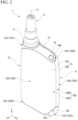
- FIG. 2 is a right perspective view of the inhaler 1 according to one embodiment.
- FIG. 3 is a front view of the inhaler 1 according to one embodiment.
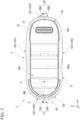
- FIG. 4 is a plan view of the inhaler 1 according to one embodiment.
- FIG. 5 is a bottom view of the inhaler 1 according to one embodiment.
- FIG. 6 is an exploded perspective view of the inhaler 1 according to one embodiment from a bottom side.
- the inhaler 1 is a so-called non-combustion-type inhaler and obtains a flavor by suctioning aerosol atomized by heating through a flavor source.
- the inhaler 1 includes a main body unit 2, a cartridge 3 (also referred to as an atomization unit), a flavor source container 4, and a mouthpiece 5.
- the cartridge 3 is housed to be insertable into and removable from a cartridge housing portion 10 of the main body unit 2.
- the flavor source container 4 is detachably attached to a heating module 11 of the main body unit 2.
- the mouthpiece 5 is detachably attached to the flavor source container 4.
- the main body unit 2 includes a housing 12.
- the housing 12 is formed in a rounded flat box shape as a whole.
- the housing 12 includes a pair of main surface portions 12A and a circumferential wall portion 12B.
- a pair of main surface portions 12A means that one main surface portion (first main surface portion 12A1) and the other main surface portion (second main surface portion 12A2) are disposed to face each other, and is not limited to a meaning that the first main surface portion 12A1 and the second main surface portion 12A2 are identical even in detailed shapes.
- the pair of main surface portions 12A refer to portions that form a set of facing surfaces (in the present embodiment, surfaces with the largest area) of the hexahedron.
- the circumferential wall portion 12B refers to a portion forming the remaining four surfaces of the hexahedron excluding the pair of main surface portions 12A.
- the circumferential wall portion 12B is also referred to as a portion that connects circumferential edges of the pair of main surface portions 12A that are disposed to face each other.
- the housing 12 includes an outer case 13, a display cover 14, and an inner case 20.
- the outer case 13 is formed by combining a first case 13A and a second case 13B.
- the first case 13A includes the first main surface portion 12A 1 and a first circumferential wall portion 12B1 provided at a circumferential edge of the first main surface portion 12A1.
- the second case 13B includes the second main surface portion 12A2 and a second circumferential wall portion 12B2 provided at a circumferential edge of the second main surface portion 12A2.
- the first circumferential wall portion 12B1 of the first case 13A, the second circumferential wall portion 12B2 of the second case 13B, the display cover 14, and the inner case 20 form the circumferential wall portion 12B.
- a mating surface of the first circumferential wall portion 12B1 of the first case 13A and the second circumferential wall portion 12B2 of the second case 13B is formed in the circumferential wall portion 12B.
- the four corner portions 12C include a first corner portion 12C1 at which the heating module 11 is disposed, a second corner portion 12C2 at which an opening of the cartridge housing portion 10 (refer to FIG. 6 ) is disposed, a third corner portion 12C3 at which a charging terminal 21 (refer to FIG. 5 ) is disposed, and a fourth corner portion 12C4 at which an input device 15 (refer to FIG. 2 ) is disposed.
- the display cover 14 is provided from the heating module 11 disposed at the first corner portion 12C1 to the fourth corner portion 12C4.
- a through hole 14a in which the input device 15 (push button) is disposed is formed in the display cover 14.
- An outer surface of the display cover 14 is lower than an outer surface of the outer case 13. That is, the input device 15 is disposed in a recessed portion.
- the input device 15 may be disposed at a position at or lower than the outer surface of the outer case 13. That is, at least a part of the input device 15 needs only be disposed at a position at or lower than the outer surface of the outer case 13. Preferably, the entirety of the input device 15 is disposed at a position at or lower than the outer surface of the outer case 13. In other words, it is preferable that a contact detection portion (button surface) of the input device 15 be disposed at a position not touching the outer surface of the outer case 13.
- the outer case 13 has an exposed portion 13b that exposes a part of the inner case 20 in the second corner portion 12C2.
- a second air inlet 18B (to be described later) that takes air (outside air) into the inside of the housing 12 is provided in a gap between the inner case 20 and the outer case 13 in the exposed portion 13b.
- the outer case 13 also has the exposed portion 13b that exposes a part of the inner case 20 at the third corner portion 12C3, but the second air inlet 18B is not provided at the third corner portion 12C3.
- a side on which the first main surface portion 12A1 is disposed is referred to as a front side
- a side on which the second main surface portion 12A2 is disposed is referred to as a rear side.
- a side on which the heating module 11 is disposed is referred to as a left side
- a side on which the input device 15 is disposed is referred to as a right side.
- the heating module 11 protrudes from the housing 12 as shown in FIG. 3 .
- a side from which the heating module 11 protrudes is referred to as an upper side
- a side opposite thereto is referred to as a lower side.
- an XYZ orthogonal coordinate system is set, and positional relationships of respective members may be described with reference to the XYZ orthogonal coordinate system.
- An X-axis direction is a front-rear direction (also referred to as a thickness direction) of the inhaler 1
- a Y-axis direction is a left-right direction (also referred to as a width direction) of the inhaler 1
- a Z-axis direction is a vertical direction (also referred to as a height direction) of the inhaler 1.
- first corner portion 12C1 (the heating module 11) is disposed at an upper left of the housing 12.
- the second corner portion 12C2 (the cartridge housing portion 10) is disposed at a lower left of the housing 12.
- the third corner portion 12C3 (the charging terminal 21) is disposed at a lower right of the housing 12.
- the fourth corner portion 12C4 is disposed at an upper right of the housing 12.
- the first corner portion 12C1 (the heating module 11) and the third corner portion 12C3 (the charging terminal 21) are disposed on a diagonal line of the housing 12.
- the second corner portion 12C2 (the cartridge housing portion 10) and the fourth corner portion 12C4 (the input device 15) are disposed on a diagonal line of the housing 12.
- the flavor source container 4 (also referred to as a tobacco capsule) shown in FIG. 6 stores a flavor source and adds flavor to the aerosol atomized by the cartridge 3.
- shredded tobacco or formed articles in which tobacco raw materials are formed into granules can be used.
- the flavor source may be formed of plants other than tobacco (for example, mint, Chinese medicine, herbs, or the like).
- a flavoring agent such as menthol may be infused into the flavor source.
- the flavor source may be one in which a flavoring agent is supported on a plant-derived carrier (such as cellulose) or other carriers (including an inorganic carrier).
- the flavor source container 4 is attached to the heating module 11 of the main body unit 2.
- FIG. 7 is a cross-sectional view taken along line VII-VII shown in FIG. 4 .
- the flavor source container 4 includes a bottomed cylindrical container main body 41 and a filter 42 that covers an opening of the container main body 41.
- a circumferential wall 41a of the container main body 41 is inserted into the inside of a capsule holder 61 of the heating module 11.
- An upper side of the circumferential wall 41a of the container main body 41 protrudes from the capsule holder 61.
- the mouthpiece 5 is attached to the upper side of the circumferential wall 41a.
- the filter 42 is formed of, for example, a nonwoven fabric.
- the filter 42 is disposed inside the circumferential wall 41a of the container main body 41. Due to the filter 42, the opening of the container main body 41 is closed, and the flavor source storage chamber 41c is formed inside the flavor source container 4. The flavor source described above is stored in the flavor source storage chamber 41c.
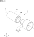
- FIG. 8 is an exploded perspective view of the mouthpiece 5 according to one embodiment.
- the mouthpiece 5 includes a cylindrical suction port 51 that is held in a user's mouth, and a suction port base 52 to which the suction port 51 is attached.
- the suction port 51 is a soft resin molded article formed of, for example, a resin material such as a silicone resin.
- the suction port base 52 is, for example, a hard resin molded article formed of a resin material such as a polypropylene resin.
- the suction port base 52 includes an insertion cylinder portion 52a inserted into the inside of the suction port 51, and an outer fitting cylinder portion 52b provided to be connected to a lower end of the insertion cylinder portion 52a and fitted onto the flavor source container 4.
- a step is formed on an outer surface between the insertion cylinder portion 52a and the outer fitting cylinder portion 52b, and an annular groove 52c recessed downward (to a -Z side) in the axial direction is formed on an upper surface of the step.
- An insertion portion 51a that is inserted into the annular groove 52c is formed at a lower end of the suction port 51.
- the cartridge 3 shown in FIG. 6 stores a liquid aerosol source and atomizes the liquid aerosol source.
- the cartridge 3 is formed in a columnar shape and is housed inside the housing 12 from the cartridge housing portion 10 provided at the bottom part of the housing 12.
- FIG. 9 is a cross-sectional view taken along line IX-IX shown in FIG. 5 .
- the cartridge 3 includes a tank 31, a gasket 32, a mesh body 33, an atomization container 34, a heater 35, and a heater holder 36.
- the tank 31 stores the aerosol source.
- the tank 31 has translucency and allows a remaining amount of liquid in the aerosol source to be ascertained.
- the outer circumferential wall 31d of the tank 31 extends to a lower side (-Z side) of a lower end of the flow path tube 31c.
- Two engaging holes 31f are formed near a lower end part of the outer circumferential wall 31d.
- the two engaging holes 31f are to fix the heater holder 36 to the tank 31.
- the two engaging holes 31f are disposed to face each other on both sides of the outer circumferential wall 31d with the main axis O sandwiched therebetween. Furthermore, in a state in which the cartridge 3 is housed in the cartridge housing portion 10, a central axis of the cartridge 3 coincides with or substantially coincides with the main axis O of the cartridge housing portion 10.
- the mesh body 33 is a porous member having a liquid absorbing property.
- the mesh body 33 is formed of, for example, a cotton-based fiber material, a glass-based fiber, or the like.
- the mesh body 33 is also formed in substantially the same annular shape as the gasket 32. That is, the flow path tube 31c can be inserted into a center of the mesh body 33 in the radial direction.
- the openings 32a of the gasket 32 are closed by the mesh body 33, and the liquid storage chamber 31g is formed inside the tank 31.
- the liquid aerosol source is stored in the liquid storage chamber 31g.
- An atomization chamber 34c is formed inside the circumferential wall 34a of the atomization container 34.
- the atomization chamber 34c is in communication with the flow path tube 31c of the tank 31.
- An opening 34e is formed in a bottom wall 34d of the atomization container 34.
- the heater 35 is disposed in the atomization chamber 34c.
- the wick 35a is a porous and substantially columnar member having a liquid absorbing property.
- the wick 35a is curved and deformed into a substantially U-shape. More specifically, the wick 35a has two axial extension portions that extend in the axial direction and a radial extension portion that connects the two axial extension portions.
- the two axial extension portions are disposed to overlap in the X-axis direction, and each of them is connected to the mesh body 33. Therefore, the aerosol source absorbed by the mesh body 33 is suctioned up by the wick 35a.
- the heating wire 35b is spirally wound around the radial extension portion of the wick 35a. Both end parts of the heating wire 35b extend toward the side on the heater holder 36 in the axial direction. Both end parts of the heating wire 35b are electrically connected to two planar electrodes 36h provided on a lower surface of a bottom wall 36d of the heater holder 36. When the heating wire 35b is energized through the two planar electrodes 36h, the wick 35a is heated. When the wick 35a is heated, the aerosol source absorbed by the wick 35a is atomized.
- the heater holder 36 is formed in a bottomed cylindrical shape.
- the circumferential wall 36a of the heater holder 36 is inserted outside the circumferential wall 34a of the atomization container 34 and inside the outer circumferential wall 3 1d of the tank 31.
- An upper end opening edge of the circumferential wall 36a is in contact with the fitting portion 34b of the atomization container 34 in the axial direction.
- Two engaging pieces 36b engaging with the two engaging holes 31f of the outer circumferential wall 31d of the tank 31 are formed at an upper end of the circumferential wall 36a.
- the gasket 32, the mesh body 33, and the atomization container 34 are incorporated in that order between the tank 31 and the heater holder 36 in the axial direction.
- the two intake holes 36c causes the outside of the cartridge 3 (a cartridge housing space 10A of the cartridge housing portion 10) to be in communication with the atomization chamber 34c. Furthermore, an intake hole 36e penetrating in the axial direction is also formed in the bottom wall 36d of the heater holder 36, but may be omitted. The intake hole 36e also causes the outside of the cartridge 3 (the cartridge housing space 10A of the cartridge housing portion 10) to be in communication with the atomization chamber 34c.
- FIG. 10 is an exploded perspective view of the main body unit 2 according to one embodiment.
- the main body unit 2 includes an inner assembly 20A in which various parts are incorporated into the inner case 20.
- the inner assembly 20A, together with a plate-shaped cushion material 19, is sandwiched between the first case 13A and the second case 13B of the outer case 13 to be covered on a front side and a rear side thereof.
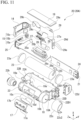
- FIG. 11 is an exploded perspective view of the inner assembly 20A according to one embodiment. Furthermore, FIG. 11 shows a state in which the heating module 11 and the cartridge housing lid 100 are removed from the inner assembly 20A.
- the inner assembly 20A includes an inner case main body 22, a power supply 23, a main substrate 24, a display device 25, a sensor 26, a light source 27, a vibrator 28, and a flexible printed circuit board 29.
- a cartridge contact portion 22b is fitted into an opening of the cartridge housing portion 10 on an upper side (+Z side) in the axial direction.
- the cartridge contact portion 22b is an elastic body formed of a resin material such as, for example, a silicone resin.
- the cartridge contact portion 22b includes a first ring portion 22b1, a cylindrical portion 22b2, and a second ring portion 22b3.
- An annular protrusion 10B protruding inward in the radial direction is formed on an inner wall surface of the cartridge housing portion 10 on an upper side (+Z side) in the axial direction.
- the first ring portion 22b1 is disposed on an upper side (+Z side) of the annular protrusion 10B in the axial direction.
- the first ring portion 22b1 has an outer diameter larger than an inner diameter of the annular protrusion 10B and extends to the inner wall surface of the cartridge housing portion 10.
- the first ring portion 22b1 is in contact with the bottom wall 41d of the flavor source container 4 inside the capsule holder 61.
- a surface side of the first ring portion 22b1 facing the bottom wall 41d of the flavor source container 4 may be a flat surface, or a groove may be formed in accordance with a shape of a leg portion of the bottom wall 41d.
- the first ring portion 22b1 serves as a slip stopper for the flavor source container 4 and a seal chamber for the fine holes 41e of the flavor source container 4. Note that, the first ring portion 22b1 may not be in contact with the bottom wall 41d of the flavor source container 4. In that case, a seal portion that prevents introduction of outside air can be formed at a contact portion in the flange portion 41b between the flavor source container 4 and the capsule holder 61.
- the cylindrical portion 22b2 is disposed radially inside the annular protrusion 10B. The cylindrical portion 22b2 connects an inner diameter side of the first ring portion 22b1 and an inner diameter side of the second ring portion 22b3 in the axial direction.
- the second ring portion 22b3 is disposed on a lower side (-Z side) of the annular protrusion 10B in the axial direction.
- the second ring portion 22b3 has an outer diameter larger than the inner diameter of the annular protrusion 10B, is in contact with a lower surface of the annular protrusion 10B, and is formed in an inverted truncated cone shape in which a diameter thereof decreases toward a lower side in the axial direction.
- a seal ring 22b4 is formed at a lower end of the second ring portion 22b3. Due to the seal ring 22b4, a contact of the second ring portion 22b3 to the cartridge 3 becomes nonplanar contact, and a contact pressure with respect to the cartridge 3 increases.
- a communication hole 22b5 is formed at a center of the first ring portion 22b1, the cylindrical portion 22b2, and the second ring portion 22b3.
- the communication hole 22b5 causes the through hole 21b of the tank 31 of the cartridge 3 described above to be in communication with the fine holes 41e of the flavor source container 4.
- the seal ring 22b4 of the second ring portion 22b3 is formed in a double ring shape.
- the seal ring 22b4 is in contact with the top wall 31a of the tank 31 around the through hole 31b of the cartridge 3, and thereby a highly airtight double seal can be formed.
- FIG. 12 is an exploded perspective view of the heating module 11 according to one embodiment.
- the heating module 11 includes a heater portion 60, the capsule holder 61 that houses the heater portion 60, and a design ring 62 that is fitted onto the capsule holder 61.
- the capsule holder 61 is a hard resin molded article formed of a resin material such as, for example, a polycarbonate resin or an ABS resin.
- the capsule holder 61 has a cylindrical shape extending in the axial direction, and a diameter thereof on an upper side in the axial direction is reduced into a truncated cone shape.
- a snap fit 61a is provided at a lower end part of the capsule holder 61 in the axial direction.
- the snap fit 61a fits into a protruding portion 10a formed on an outer circumferential surface of the cartridge housing portion 10 shown in FIG. 11 .
- a stopper ring 22c is fitted onto a lower end part 10b of the cartridge housing portion 10.
- the stopper ring 22c is formed of, for example, an alumite-treated aluminum material or the like.
- a first opening 10c is formed in a circumferential surface on a left side (-Y side) of the cartridge housing portion 10. The first opening 10c is formed in a long hole shape extending in the axial direction.
- the cover member 17 is adhered to the circumferential surface on the left side (-Y side) of the cartridge housing portion 10 via an adhesive sheet 17b.
- the cover member 17 has translucency and closes the first opening 10c. Therefore, a remaining amount of liquid in the aerosol source of the cartridge 3 housed in the cartridge housing portion 10 can be ascertained through the cover member 17 and the first opening 10c.
- Two communication holes 17a are formed in the cover member 17. Also, two communication holes 10d in communication with the two communication holes 17a are also formed in the cartridge housing portion 10. The communication holes 17a and 10d causes each of the first air inlet 18A and the second air inlet 18B shown in FIG. 1 to be in spatial communication with the cartridge housing space 10A inside the cartridge housing portion 10.
- the power supply housing portion 22A has an opening on the front side (+X side) and houses the power supply 23 from the opening.
- the power supply 23 is formed in a columnar shape extending in the Z-axis direction.
- the power supply 23 is electrically connected to the main substrate 24 via a wiring.
- the power supply 23 is, for example, a storage battery (secondary battery) and can be charged via the charging terminal 21 provided on the main substrate 24.
- the power supply 23 is not limited to a chargeable and dischargeable secondary battery, and may be a super capacitor or the like.
- the power supply 23 may be a primary battery. Note that, if the power supply 23 is a primary battery, the charging terminal 21 is not necessary.
- the inner case main body 22 includes a top plate 22B, a side plate 22C, and a bottom plate 22D that surround the power supply housing portion 22A.
- the cartridge housing portion 10 is disposed at a position facing the side plate 22C in the left-right direction (Y-axis direction), and all four sides of the power supply 23 are surrounded by the top plate 22B, the side plate 22C, the bottom plate 22D, and the cartridge housing portion 10.
- the top plate 22B faces an upper end part of the power supply 23 with a gap therebetween in the Z-axis direction.
- a disc-shaped cushion material 23a is inserted into the gap between the top plate 22B and the power supply 23.
- the bottom plate 22D faces a lower end part of the power supply 23 with a gap therebetween in the Z-axis direction.
- the disc-shaped cushion material 23a is inserted into the gap between the bottom plate 22D and the power supply 23.
- the top plate 22B holds the display device 25 and the input device 15.
- the display device 25 is, for example, an organic EL display, a liquid crystal display, or the like.
- the display device 25 is electrically connected to the main substrate 24 via a flexible printed circuit board 25a.
- the display device 25 is disposed on a lower side (-Z side) of the display cover 14.
- the display cover 14 is snap-fitted to both left and right end parts of the top plate 22B.
- the display cover 14 has translucency and allows a display surface of the display device 25 to be ascertained.
- the input device 15 is, for example, a push button.
- the input device 15 includes a switch button 15a, a switch holder 15b, and a switch substrate 15c.
- the switch substrate 15c is provided at a second end part 29b of the flexible printed circuit board 29.
- the switch button 15a is disposed on the switch substrate 15c.
- the switch button 15a is assembled to the side on the display cover 14 via the switch holder 15b.
- the input device may be a touch panel. That is, the input device 15 needs only be a contact detection portion.
- a second opening 10e is formed on a circumferential surface on a right side (+Y side) of the cartridge housing portion 10.
- the second opening 10e is formed in a long hole shape extending in the axial direction.
- a sensor holder 26a is adhered to a circumferential surface on a right side (-Y side) of the cartridge housing portion 10 via an adhesive sheet 26c.
- the sensor holder 26a holds the sensor 26.
- the sensor 26 is a so-called puff sensor that detects user's suction.
- a pressure sensor that detects a pressure
- an airflow sensor that detects a flow of air
- a temperature sensor that detects a temperature, or the like can be exemplified.
- a side facing the cartridge housing portion 10 serves as a detection portion.
- the detection portion detects, for example, behavior of a diaphragm that deforms according to pressure fluctuations as a change in capacitance.
- a pedestal portion 26b is formed in the sensor holder 26a.
- the light source 27 is placed on the pedestal portion 26b.
- the light source 27 is, for example, an LED light, or the like.
- the sensor holder 26a has translucency and also serves as a light guide member that guides light of the light source 27 into the cartridge housing portion 10.
- This sensor holder 26a is formed of, for example, a polycarbonate resin.
- the polycarbonate resin provides the sensor holder 26a that holds the sensor 26 with appropriate hardness and satisfactory translucency so that it can also serve as a light guide member.
- As the translucency of the sensor holder 26a it is preferable to have a lower transmittance than transparency in such a manner that transmitted light is diffused.
- the light source 27 is electrically connected to a sub-substrate 27a.
- the vibrator 28 is electrically connected to the sub-substrate 27a via a wiring.
- the vibrator 28 is in contact with the side on the second case 13B (refer to FIG. 22 described later).
- the vibrator 28 operates at a predetermined timing (for example, at a timing at which the input device 15 is pressed, or the like) to cause the outer case 13 to vibrate.
- the sub-substrate 27a is electrically connected to the main substrate 24 via a third end part 29c of the flexible printed circuit board 29.
- the main substrate 24 is held by the side plate 22C.
- the main substrate 24 has a plate shape extending along an X-Z plane.
- the charging terminal 21 is mounted on the lower end part of the main substrate 24.
- the main substrate 24 is connected to various electronic parts described above directly or indirectly via the flexible printed circuit board 29.
- the "main substrate” refers to a largest substrate among substrates housed inside the housing 12.
- the main substrate 24 is larger than the sub-substrate 27a, the switch substrate 15c of the input device 15, or the like described above. Note that, if only one substrate is housed inside the housing 12, that substrate is the "main substrate”. Also, if two substrates of the same size are housed inside the housing 12, a substrate in which an arithmetic unit for electronic control such as a CPU or a microcomputer is provided is referred to as the "main substrate”.
- the flexible printed circuit board 29 includes a first end part 29a electrically connected to the main substrate 24, the second end part 29b electrically connected to the switch substrate 15c, the third end part 29c electrically connected to the sub-substrate 27a, and a fourth end part 29d in which a contact pad 29e is provided.
- the contact pad 29e (the fourth end part 29d) is held by the bottom plate 22D.
- a cap member 22d that covers the charging terminal 21 is attached to the bottom plate 22D.
- a bearing portion 22D1 on which the cartridge housing lid 100 is mounted is formed on the bottom plate 22D.
- the cartridge housing lid 100 shown in FIG. 6 opens and closes the cartridge housing portion 10 provided at the bottom part of the housing 12.
- the cartridge housing lid 100 of a pivot type (hinge type) is attached to the housing 12 (the inner case 20).
- the cartridge housing lid 100 includes a protruding electrode 101, an electrode holder 110, a seal portion 120, a metal holder 130, an electrode substrate 140, a slide cover 150, a locking piece 160, a first biasing member 170, a lid base 180, a rotation shaft 190, and a second biasing member 200.
- the seal portion 120 is a soft resin molded article formed of, for example, a resin material such as a silicone resin.
- the seal portion 120 includes a plate-shaped base portion 121 and a cylindrical portion 122 that protrudes upward from an upper surface of the base portion 121.
- a left side (-Y side) is formed in a semicircular shape in a plan view
- a right side (+Y side) is formed in a rectangular shape in a plan view.
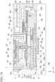
- annular protrusion 124 protruding upward is formed around the cylindrical portion 122 on the upper surface of the base portion 121. That is, the annular protrusion 124 protrudes in a direction of closing the opening of the cartridge housing portion 10 (in a tangential direction of counterclockwise in the present embodiment) in a rotation direction of the cartridge housing lid 100 (circumferential direction around the X-axis). As shown in FIG. 14 , the annular protrusion 124 is in contact with a lower end opening edge of the cartridge housing portion 10 from below and is elastically deformed. Therefore, the opening of the cartridge housing portion 10 is airtightly sealed over the entire circumference.
- the metal holder 130 is formed of a metal material with high strength such as, for example, stainless steel.
- the metal holder 130 is formed, for example, by press-processing a metal plate.
- Three through holes 131 in communication with the three through holes 123 of the seal portion 120 are formed in the metal holder 130.
- the three protruding portions 112 of the electrode holder 110 are inserted into the three through holes 131 of the metal holder 130.
- a rectangular opening 132 is formed on a right side (+Y side) of the three through holes 131 of the metal holder 130.
- a pair of slide rails 133 are formed on the metal holder 130.
- the pair of slide rails 133 are formed by bending both sides of the metal holder 130 in the X-axis direction into a crank shape.
- an insertion portion 134 is formed further to the right side (+Y side) than the opening 132 of the metal holder 130.
- the insertion portion 134 is inserted into an insertion groove 185 formed in the lid base 180 in the Y-axis direction.
- the electrode substrate 140 is a rigid substrate in which a conductor wiring such as copper is provided on an insulator such as, for example, polychlorinated biphenyl.
- the electrode substrate 140 is attached to a lower surface of the metal holder 130 by fitting or adhesion.
- Three through holes 141 in communication with the three through holes 131 of the metal holder 130 are formed in the electrode substrate 140.
- the three protruding electrodes 101 protruding from lower ends of the three through holes 123 of the seal portion 120 are inserted into the three through holes 141 of the electrode substrate 140.
- Three spring contacts 142 are provided on a right side (+Y side) of the three through holes 141 of the electrode substrate 140.
- the three spring contacts 142 are disposed at positions corresponding to the opening 132 of the metal holder 130.
- the three spring contacts 142 are electrically connected to the three protruding electrodes 101 via a conductor wiring which is not shown in the drawings.
- the three spring contacts 142 are in contact with the contact pad 29e in a state in which the cartridge housing lid 100 is closed. That is, in a state in which the cartridge housing lid 100 is closed, the three protruding electrodes 101 are electrically connected to the main substrate 24 via the contact pad 29e and are controlled for energization.
- the slide cover 150 is a hard resin molded article formed of a resin material such as, for example, a polycarbonate resin or an ABS resin.
- the slide cover 150 includes a cover bottom wall 151 that forms a lower surface (cover surface) of the cartridge housing lid 100, and a cover circumferential wall 152 that protrudes upward from a circumferential edge part of the cover bottom wall 151.
- a left side (-Y side) is formed in a semicircular shape in a plan view
- a right side (+Y side) is formed in a rectangular shape in a plan view.
- a left side (-Y side) of the cover circumferential wall 152 is formed in a semicircular arc shape in a plan view.
- a right side (+Y side) of the cover circumferential wall 152 extends parallel to the left-right direction (Y-axis direction) from both end parts of the semicircular arc-shaped portion.
- An upper end part 152a of the semicircular arc-shaped portion of the cover circumferential wall 152 is in contact with the lower surface of the metal holder 130 to be slidable in the Y-axis direction.
- a through hole 156 through which a claw portion 161 of the locking piece 160 is inserted in the Y-axis direction and disposed is formed in the semicircular arc-shaped portion of the cover circumferential wall 152.
- a pedestal portion 153, a cover slide groove 154, and a lock release groove 155 are each provided in pairs at the front and rear.
- the pair of pedestal portions 153 are in contact with the electrode substrate 140, which is disposed inside the cover circumferential wall 152, to be slidable in the Y-axis direction.
- the pair of slide rails 133 of the metal holder 130 engage with the pair of cover slide grooves 154 to be slidable in the Y-axis direction.
- a pair of locked portions 162 of the locking piece 160 engage with the pair of lock release grooves 155 to be slidable in the Y-axis direction.
- the "side against which the locking piece 160 is pressed” can be rephrased as a front side (-Y side) in a biasing direction if the first biasing member 170 is a coil spring.
- the "side opposite to the side against which the locking piece 160 is pressed” can be rephrased as a rear side (+Y side) in the biasing direction if the first biasing member 170 is a coil spring.
- a front side in a rotational direction (also referred to as a downstream side in the rotational direction) of the locking piece 160 is the "side against which the locking piece 160 is pressed”
- a rear side in the rotational direction (also referred to as an upstream side in the rotational direction) of the locking piece 160 is the "side opposite to the side against which the locking piece 160 is pressed”.
- the locking portion 155a forms an end part on a left side (-Y side) of the lock release groove 155.
- the locking portion 155a forms an X-Z plane that faces the locked portion 162 of the locking piece 160 in the Y-axis direction and is in surface contact with the locked portion 162.
- the guide portion 155b extends to a right side (+Y side) from the locking portion 155a. An end part on the right side (+Y side) of the guide portion 155b is open.
- the slide rail 133 of the metal holder 130 is disposed on a side (+Y side) opposite to the side against which the locking piece 160 is pressed.
- the slide rail 133 faces the locked portion 162 of the locking piece 160 with a gap therebetween in the Y-axis direction. That is, the slide rail 133 prevents the locked portion 162 from coming off the guide portion 155b.
- unevenness 150a extending in a direction intersecting the biasing direction (Y-axis direction) of the first biasing member 170 is formed on a cover surface (lower surface of the cover bottom wall 151) of the slide cover 150 facing a side opposite to the locking piece 160 (-Z side).
- the unevenness 150a of the present embodiment extends in the X-axis direction orthogonal to the biasing direction (Y-axis direction), and has recessed portions and protruding portions formed alternately in the biasing direction. Therefore, the slide cover 150 can be slid in the Y-axis direction by hooking a user's finger or the like on the unevenness 150a.
- the unevenness 150a is not limited to a linear groove (or a protrusion) extending in the X-axis direction, but may be a V-shaped groove (or a protrusion) in a bottom view.
- a pair of protruding portions 157 are provided on upper end parts of the parallel portions of the cover circumferential wall 152 to protrude upward.
- the pair of protruding portions 157 are disposed on a side (+Y side) opposite to the side against which the locking piece 160 is pressed with respect to a pair of front and rear edge parts 135 provided at a semicircular portion on a left side (-Y side) of the metal holder 130.
- the pair of edge parts 135 face the pair of protruding portions 157 in the Y-axis direction. That is, the pair of edge parts 135 prevent the slide cover 150 biased by the first biasing member 170 from coming off.
- the locking piece 160 is a hard resin molded article formed of a resin material such as, for example, a polyacetal resin.
- the locking piece 160 includes a claw portion 161, the pair of locked portions 162, and a spring attachment portion 163.
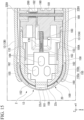
- the claw portion 161 is formed on a front side (-Y side) of the locking piece 160 in the biasing direction. As shown in FIG. 15 , the claw portion 161 protrudes from the through hole 156 of the cover circumferential wall 152 to the front side (-Y side) in the biasing direction in a state in which with the locked portion 162 is in contact with the locking portion 155a of the slide cover 150. In this state, the claw portion 161 is locked to the stopper ring 22c. Therefore, the cartridge housing lid 100 is locked in a closed state.
- the stopper ring 22c includes a collision wall 22c1, a surrounding wall 22c2, and a locked piece 22c3.
- the collision wall 22c1 is a portion into which the claw portion 161 in a locked state is inserted, and a thickness of the stopper ring 22c is partially reduced. Therefore, the collision wall 22c1 is easily vibrated, and when the locking piece 160 collides therewith at the time of closing the cartridge housing lid 100, a metallic sound like a clicking sound is generated from the collision wall 22c1, and the user can recognize that the lock has been applied.
- the surrounding wall 22c2 surrounds the cover circumferential wall 152 of the slide cover 150 in a state in which the cartridge housing lid 100 is closed.
- the surrounding wall 22c2 extends to a position below the lower surface (cover surface) of the cover bottom wall 151.
- the surrounding wall 22c2 only needs to extend to at least the same position as the lower surface of the cover bottom wall 151.
- the surrounding wall 22c2 only needs to extend to a position below the lower surface of the cover bottom wall 151. If the surrounding wall 22c2 extends below the lower surface of the cover bottom wall 151 as in the present embodiment, since the cover surface of the cartridge housing lid 100 is disposed at a position not touching a lower end of the surrounding wall 22c2, the cartridge housing lid 100 can be completely surrounded.
- the locked piece 22c3 is provided to protrude from a lower side of the collision wall 22c1 to the right side (+Y side) on an inner wall surface of the stopper ring 22c.
- an upper surface side is planar and a lower surface side is inclined.
- the locked piece 22c3 can move the locking piece 160 to the right side (+Y side) against the biasing of the first biasing member 170 due to the inclined surface on the lower surface side when the cartridge housing lid 100 is closed.
- the locked piece 22c3 can lock the claw portion 161 that has protruded to the -Y side due to the biasing of the first biasing member 170 on its plane on the upper surface side.
- the lid base 180 is a hard resin molded article formed of a resin material such as, for example, a polycarbonate resin or an ABS resin.
- the lid base 180 includes an insertion hole 181 and an accommodating groove 182 as shown in FIG. 13 , and the spring attachment portion 183, a slide groove 184, and the insertion groove 185 as shown in FIG. 14 .
- the insertion hole 181 penetrates the lid base 180 in the X-axis direction.
- the rotation shaft 190 is inserted into the insertion hole 181.
- the rotation shaft 190 is formed of, for example, a metal material with high strength such as, for example, stainless steel.
- the accommodating groove 182 is disposed on an extension line of the insertion hole 181.
- the second biasing member 200 is accommodated in the accommodating groove 182 as shown in FIG. 15 .
- the second biasing member 200 is formed of a spring member such as, for example, a torsion spring. Note that, the second biasing member 200 is not limited to a spring member as long as it biases in a direction of opening the cartridge housing lid 100 (counterclockwise around the rotation shaft 190 in the present embodiment) in the rotation direction of the cartridge housing lid 100, and may be an elastic body such as rubber.
- the cartridge housing lid 100 opens at an acute angle ⁇ 1 as shown in FIG. 17 due to biasing of the second biasing member 200 when it is unlocked by the locking piece 160.
- the acute angle ⁇ 1 is set to, for example, approximately 85° with respect to a bottom surface of the main body unit 2 (the housing 12). Note that, the acute angle ⁇ 1 is not limited to 85° as long as it is an angle that allows the cartridge 3 to be inserted into the cartridge housing portion 10 without interfering with the cartridge housing lid 100.
- the main body unit 2 includes a physical stopper 22d1 that allows the cartridge housing lid 100 to be opened at the acute angle ⁇ 1 or more.
- the physical stopper 22d1 of the present embodiment is formed of a cap member 22d attached to the inner case main body 22.
- the cartridge housing lid 100 can be opened to an angle ⁇ 2 at which the slide groove 184 of the lid base 180 comes into contact with the physical stopper 22d1.
- the angle ⁇ 2 is set to be, for example, an obtuse angle of approximately 95° with respect to the bottom surface of the main body unit 2 (the housing 12). Note that, the angle ⁇ 2 may be an acute angle instead of the obtuse angle or may be a right angle of 90° as long as it is larger than the acute angle ⁇ 1.
- the slide groove 184 is formed on a lower surface side of the lid base 180.
- the slide groove 184 is a portion on which the cover bottom wall 151 of the slide cover 150 slides and is recessed upward by a thickness of the cover bottom wall 151.
- the insertion portion 134 of the metal holder 130 is inserted into the insertion groove 185 as described above.
- FIG. 18 is a left side view of the inhaler 1 according to one embodiment.
- FIG. 19 is a left side view of the inhaler 1 according to one embodiment in a state in which the outer case 13 is removed. Note that, in FIG. 19 , a first air flow path 70 and a second air flow path 80 are expressed by adding a dot pattern to improve visibility of them.
- the first air inlet 18A and the second air inlet 18B are formed in the circumferential wall portion 12B of the housing 12.
- the first air inlet 18A takes air into the cartridge housing space 10A from the window 16 between the adjacent corner portions 12C (in the present embodiment, the first corner portion 12C1 and the second corner portion 12C2) of the circumferential wall portion 12B.
- the housing 12 includes the opening 13a formed between the adjacent corner portions 12C of the circumferential wall portion 12B and the cover member 17 provided in the opening 13a, and the first air inlet 18A is formed in a gap between the cover member 17 and the opening 13a.
- FIG. 20 is a perspective view of the cover member 17 according to one embodiment.
- FIG. 21 is a rear view of the cover member 17 according to one embodiment.
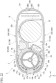
- FIG. 22 is a cross-sectional view taken along line XXII-XXII shown in FIG. 3 .
- the cover member 17 includes a first outer protrusion 17A, a plate portion 17B, an inner protrusion 17C (refer to FIG. 21 ), and a second outer protrusion 17D.
- the first outer protrusion 17A is formed on a surface of the plate portion 17B facing the outside (-Y side). As shown in FIG. 22 , the first outer protrusion 17A is inserted into the opening 13a of the outer case 13.
- the cover member 17 has translucency, and a remaining amount of liquid in the aerosol source of the cartridge 3 housed in the cartridge housing portion 10 can be ascertained through the first outer protrusion 17A.
- the first outer protrusion 17A is formed in a long hole shape extending in a main axis direction (Z-axis direction) similarly to the opening 13a of the outer case 13.
- the first outer protrusion 17A is slightly smaller than the opening 13a.
- the first air inlet 18A is formed in a gap between the first outer protrusion 17A and the opening 13a. Note that, a part of the first outer protrusion 17A may be in contact with an inner wall surface of the opening 13a.
- the first air inlet 18A is an inlet of the first air flow path 70 that takes outside air into the housing 12 due to user's suction.
- the first air inlet 18A is formed in an annular shape along an opening edge of the opening 13a (also referred to as a circumferential edge of the first outer protrusion 17A) of the outer case 13.
- a size of the first air inlet 18A is preferably such that it cannot be completely blocked by the user's finger.
- a dimension of the first air inlet 18A in the main axis direction (Z-axis direction) is preferably equal to or larger than a first interphalangeal width (for example, 2.0 cm or more) of an average adult's thumb.
- a distance in the X-axis direction between two slits extending parallel to each other in the main axis direction of the first air inlet 18A may be equal to or larger than a first interphalangeal width of an average adult's thumb.
- the communication holes 17a are disposed at locations at which the cover member 17 and the outer case 13 overlap. That is, the communication holes 17a are disposed inside the outer case 13 and are covered with the outer case 13. Therefore, the communication holes 17a cannot be visually noticeable from the outside of the outer case 13. Also, the communication holes 17a cannot be directly blocked with a finger unless the outer case 13 is removed.
- the communication holes 17a cause the first air inlet 18A to be in fluid communication with the inside of the cartridge housing portion 10.
- the communication holes 17a are in communication with the communication holes 10d formed in the cartridge housing portion 10, and cause the first air inlet 18A to be in fluid communication with the inside of the cartridge housing portion 10 over a short distance. Note that, if the communication holes 10d are not formed, air taken into the inside of the housing 12 from the communication holes 17a flows into the inside of the cartridge housing portion 10 through all the gaps in the cartridge housing portion 10.
- the first air flow path 70 forms a space (flow path) that connects the first air inlet 18A and the communication holes 17a.
- the first air flow path 70 has a flat surface portion 71 and two recessed portions 72.
- the flat surface portion 71 is formed around the first outer protrusion 17A on the plate portion 17B.
- the flat surface portion 71 is a part of a curved surface of the plate portion 17B on the side on the outer case 13 (-Y side) made into a flat surface, and is recessed to the +Y side from a surface of the first outer protrusion 17A.
- a pair of second outer protrusions 17D are disposed above and below the first outer protrusion 17A with the flat surface portion 71 sandwiched therebetween.
- the pair of second outer protrusions 17D support a mating surface of the outer case 13 from the inside.
- the two recessed portions 72 are formed at an end edge on the +X side and an end edge on the -X side of the flat surface portion 71.
- the recessed portions 72 each have a bottom surface that is lower on the +Y side than the flat surface portion 71. That is, the recessed portion 72 is recessed to the -Y side with respect to the flat surface portion 71.
- the communication hole 17a is formed on the bottom surface of the recessed portion 72.
- the bottom surface of the recessed portion 72 is formed to be wider than an opening area of the communication hole 17a.
- the inner protrusion 17C is formed on an inner surface of the plate portion 17B on the side of the cartridge housing portion 10 (+Y side). As shown in FIG. 22 , the inner protrusion 17C is inserted into the first opening 10c formed on the circumferential surface of the cartridge housing portion 10.
- the inner protrusion 17C is formed in a long hole shape extending in the main axis direction (Z-axis direction) similarly to the first opening 10c of the cartridge housing portion 10.
- the second air inlet 18B takes air into the cartridge housing space 10A from the second corner portion 12C2 of the circumferential wall portion 12B.
- the housing 12 includes the inner case 20 and the outer case 13 that covers the inner case 20 and has the exposed portion 13b in which a part of the inner case 20 is exposed at the corner portion 12C.
- the second air inlet 18B is formed in a gap between the inner case 20 and the outer case 13 in the exposed portion 13b.
- FIG. 23 is an enlarged view of a region A shown in FIG. 5 .
- the second air inlet 18B is formed in an arc shape in the gap between the inner case 20 and the outer case 13.
- the second air inlet 18B opens toward the -Z side. That is, the second air inlet 18B is at a different location from the first air inlet 18A, and has a direction of the opening different from that of the first air inlet 18A, which faces the -Y side, by 90°.
- an edge part of the exposed portion 13b of the outer case 13 is convexly curved to the +Z side.
- the housing 12 has a protruding portion 90 around the second air inlet 18B.
- the protruding portion 90 is formed by the outer case 13. That is, the protruding portion 90 is formed by a step between the inner case 20 and the outer case 13. That is, even if the user's finger touches the periphery of the second air inlet 18B, since the protruding portion 90 (the outer case 13) around the exposed portion 13b serves as a step and forms a gap between itself and the user's finger, the second air inlet 18B is less likely to be blocked.
- the protruding portion 90 is not limited to being formed by the outer case 13, and may be formed by causing a part of the inner case 20 to protrude.
- the housing 12 includes the first air flow path 70 that causes the first air inlet 18A to be in communication with the communication hole 17a, and the second air flow path 80 that causes the second air inlet 18B to be in communication with the communication hole 17a.
- the second air flow path 80 extends to the +Z side from the exposed portion 13b of the second corner portion 12C2, and reaches the communication hole 17a via a part of the first air flow path 70.
- the second air flow path 80 is bent into an angulated U-shape (substantially C-shape) until it reaches a joining position with the first air flow path 70. As shown in FIG.
- the bent portion of the second air flow path 80 is formed to bypass a pair of inner case side protrusions 81 provided on an outer surface of the inner case 20 and an outer case side protrusion 82 (refer to FIG. 10 ) that fits into the pair of inner case side protrusions 81.
- the first air flow path 70 has a flow path length to the communication hole 17a smaller than that of the second air flow path 80. That is, the first air flow path 70 has lower airflow resistance than the second air flow path 80. Therefore, a larger amount of air flows through the first air flow path 70 than through the second air flow path 80. Therefore, in normal use, the first air inlet 18A serves as a main air inlet, and the second air inlet 18B serves as a sub air inlet when the first air inlet 18A is blocked.
- the communication hole 17a has a flow path cross-sectional area smaller than either the first air inlet 18A or the second air inlet 18B. Therefore, even if either the first air inlet 18A or the second air inlet 18B is blocked, since the flow path cross-sectional area is finally reduced at the communication hole 17a, a flow rate and flow velocity of the air suctioned into the cartridge housing space 10A can be kept substantially constant. That is, the communication hole 17a functions as an air resistance rate controlling portion.
- the flow path cross-sectional area of one of the communication holes 17a needs only be smaller than an opening area of the first air inlet 18A (refer to FIG. 18 ) in the gap between the opening 13a of the outer case 13 and the first outer protrusion 17A of the cover member 17.
- the flow path cross-sectional area of one of the communication holes 17a needs only be smaller than an opening area of the second air inlet 18B (refer to FIG. 23 ) in the gap between the outer case 13 and the inner case 20 in the exposed portion 13b of the second corner portion 12C2. More preferably, the flow path cross-sectional area of one of the communication holes 17a needs only be smaller than a minimum flow path cross-sectional area of each of the first air flow path 70 and the second air flow path 80.
- the cartridge housing lid 100 provided at the bottom part of the housing 12 of the main body unit 2 is opened.
- a finger is placed on the unevenness 150a provided on a cover surface of the slide cover 150, and the slide cover 150 is moved to the +Y side.
- the slide cover 150 is locked to the locked portion 162 of the locking piece 160. Therefore, when the slide cover 150 is moved to the +Y side, the locking piece 160 can be moved to the +Y side, and a locked state against the stopper ring 22c due to the locking piece 160 can be released as shown in FIG. 16 .
- the cartridge housing lid 100 opens due to the biasing of the second biasing member 200.
- the cartridge housing lid 100 is opened, the cartridge 3 is housed in the cartridge housing portion 10.
- the cartridge housing lid 100 is closed against the biasing of the second biasing member 200.
- the claw portion 161 of the locking piece 160 comes into contact with the inclined surface on a lower side of the locked piece 22c3, and the locking piece 160 moves to the +Y side against the biasing of the first biasing member 170. Therefore, the locking piece 160 can get over the locked piece 22c3.
- the flavor source container 4 and the mouthpiece 5 may be attached to the heating module 11 of the main body unit 2 before the cartridge 3 is inserted, but if not, the flavor source container 4 and the mouthpiece 5 may be attached to the heating module 11 after the cartridge 3 is inserted, thereby completing the assembly of the inhaler 1.
- the user first presses the input device 15 shown in FIG. 2 .
- the main body unit 2 may be programmed to be activated by pressing the input device 15 a plurality of times.
- the heating module 11 heats the flavor source container 4 to enhance the flavor.
- the user suctions while holding the mouthpiece 5 in the user's mouth.
- air inside the cartridge housing portion 10 flows, and the sensor 26 shown in FIG. 22 detects a puff.
- the heating wire 35b of the cartridge 3 shown in FIG. 9 is energized, and the heating wire 35b generates heat.
- the heating wire 35b generates heat
- the liquid aerosol source impregnated in the wick 35a is heated and atomized.
- the atomized aerosol is suctioned up along with air (outside air) taken in by the suction.
- the atomized aerosol fills the atomization chamber 34c, and is suctioned upward together with the air that has flowed into the atomization chamber 34c through the flow path tube 31c, the through hole 31b, and the communication hole 22b5 of the cartridge contact portion 22b. Thereafter, mixed gas of the atomized aerosol and the air enters a user's mouth through the flavor source container 4 and the mouthpiece 5. Therefore, the user can taste the flavor.
- the cartridge housing lid 100 described above includes the lid base 180 that includes the rotation shaft 190 provided thereto and rotates around the rotation shaft 190 as a center, the locking piece 160 connected to the rotation end part 180A of the lid base 180 via the first biasing member 170, and the slide cover 150 covering the locking piece 160 and attached to the lid base 180 to be slidable in a biasing direction in which the locking piece 160 is biased, in which the slide cover 150 includes the locking portion 155a disposed on a side against which the locking piece 160 is pressed by biasing of the first biasing member 170 to lock the locking piece 160, and the guide portion 155b that allows the locking piece 160 moving away from the locking portion 155a to move toward a side opposite to the side against which the locking piece 160 is pressed.
- the unevenness 150a extending in a direction intersecting the biasing direction is formed on the cover surface of the slide cover 150 facing a side opposite to the locking piece 160.
- the protruding electrode 101 (electrode) disposed on a side of the locking piece 160 opposite to the slide cover 150 is provided, and the long hole 164 extending in the biasing direction to avoid interference with the protruding electrode 101 is provided in the locking piece 160.
- the main body unit 2 of an aerosol generator of the present embodiment includes the cartridge housing portion 10 that houses the cartridge 3, and the cartridge housing lid 100 that opens and closes the opening of the cartridge housing portion 10.
- the cartridge housing lid 100 since the above-described cartridge housing lid 100 is incorporated, the cartridge housing lid 100 is easily closed, and airtightness of the cartridge housing portion 10 is easily secured.
- the cartridge housing portion 10 includes the surrounding wall 22c2 that surrounds the cover circumferential wall 152 (circumferential edge part) of the cartridge housing lid 100 in a state in which the cartridge housing lid 100 is closed.
- the cover circumferential wall 152 of the cartridge housing lid 100 is completely covered with the surrounding wall 22c2 of the main body unit 2. Therefore, even if the main body unit 2 falls, damage to or displacement of the cartridge housing lid 100 can be suppressed, and airtightness of the cartridge housing portion 10 can be easily secured.
- the cartridge housing portion 10 includes the locked piece 22c3 having an inclined surface that moves the locking piece 160 against the biasing of the first biasing member 170 when the cartridge housing lid 100 is closed.
- the locking piece 160 can be moved by the inclined surface of the locked piece 22c3 without sliding the slide cover 150 when the cartridge housing lid 100 is closed.
- the cartridge housing portion 10 includes the collision wall 22c1 with which a distal end of the locking piece 160 collides due to biasing of the first biasing member 170 after the locking piece 160 passes the locked piece 22c3.
- the collision wall 22c1 is formed of a metal.
- the second biasing member 200 which biases in a direction of opening the cartridge housing lid 100 in a rotation direction of the cartridge housing lid 100 is provided.
- the cartridge housing lid 100 opens at an acute angle ⁇ 1 with respect to the cartridge housing portion 10 due to the biasing of the second biasing member 200.
- the physical stopper 22d1 that allows the cartridge housing lid 100 to be opened at an acute angle ⁇ 1 or more is provided.
- the cartridge housing lid 100 includes the seal portion 120 that seals the opening of the cartridge housing portion 10, and the seal portion 120 includes the annular protrusion 124 that protrudes in a direction of closing the opening of the cartridge housing portion 10 in the rotation direction of the cartridge housing lid 100.
- the aerosol generator of the present embodiment includes the main body unit 2, and the cartridge 3 that stores the aerosol source and is inserted into the cartridge housing portion 10 of the main body unit 2.
- the cartridge housing lid 100 is easily closed, and airtightness of the cartridge housing portion 10 is easily secured.
- the non-combustion-type inhaler of the present embodiment includes the aerosol generator described above and the flavor source container 4 attached to the aerosol generator.
- the main body unit 2 of the aerosol generator of the present embodiment described above includes the housing 12 in which the cartridge housing space 10A is provided therein, in which the housing 12 includes the pair of the main surface portions 12A, the circumferential wall portion 12B connecting the pair of main surface portions 12A and in which the plurality of corner portions 12C are provided, the first air inlet 18A taking air into the cartridge housing space 10A from between the pair of main surface portions 12A or the adjacent corner portions 12C of the circumferential wall portion 12B, and the second air inlet 18B taking air into the cartridge housing space 10A from the corner portion 12C of the circumferential wall portion 12B.
- locations of the first air inlet 18A and the second air inlet 18B are completely different, thereby it is difficult to block both the first air inlet 18A and the second air inlet 18B.
- the first air inlet 18A may be provided not only between the adjacent corner portions 12C of the circumferential wall portion 12B but also in the pair of main surface portions 12A. That is, a through hole for forming the first air inlet 18A may be provided in either one of the pair of main surface portions 12A. Even in this case, both the first air inlet 18A and the second air inlet 18B being blocked can be suppressed.
- the housing 12 includes the inner case 20 and the outer case 13 that covers the inner case 20 and has the exposed portion 13b in which a part of the inner case 20 is exposed at the corner portion 12C, in which the second air inlet 18B is formed in a gap between the inner case 20 and the outer case 13 in the exposed portion 13b.
- the second air inlet 18B is formed in a gap between the inner case 20 and the outer case 13 exposed in the corner portion 12C of the housing 12 and has a completely different form from the first air inlet 18A formed at a position other than the corner portion 12C of the housing 12, thereby it is difficult to block both the first air inlet 18A and the second air inlet 18B.
- an edge part of the exposed portion 13b is curved.
- the edge part of the exposed portion 13b is not a straight line but is curved, even if it is touched by a user's finger, the second air inlet 18B is less likely to be blocked completely.
- the housing 12 has the protruding portion 90 around the second air inlet 18B.
- the second air inlet 18B is less likely to be blocked.
- the housing 12 has the protruding portion 90 around the second air inlet 18B, and the protruding portion 90 is formed by the outer case 13.
- the housing 12 includes the communication hole 17a in communication with the cartridge housing space 10A, the first air flow path 70 that causes the first air inlet 18A to be in communication with the communication hole 17a, and the second air flow path 80 that causes the second air inlet 18B to be in communication with the communication hole 17a, in which the first air flow path 70 has lower airflow resistance than the second air flow path 80.
- the first air inlet 18A and the second air inlet 18B can be suitably used as a main air inlet and a sub air inlet.
- the first air flow path 70 has a flow path length to the communication hole 17a smaller than that of the second air flow path 80.
- the first air flow path 70 has lower airflow resistance than the second air flow path 80, thereby it is easy to suction air from the main first air inlet 18A.
- the communication hole 17a has a flow path cross-sectional area smaller than either the first air inlet 18A or the second air inlet 18B.
- the housing 12 includes the opening 13a formed between the adjacent corner portions 12C of the circumferential wall portion 12B and the cover member 17 provided in the opening 13a, and the first air inlet 18A is formed in a gap between the cover member 17 and the opening 13a.
- the first air inlet 18A is formed in a gap between the opening 13a of the housing 12 and the cover member 17 provided in the opening 13a, the first air inlet 18A is less likely to be blocked by a finger.
- the aerosol generator of the present embodiment includes the main body unit 2 and the cartridge 3 that stores the aerosol source and is inserted into the cartridge housing space 10A of the main body unit 2.
- the non-combustion-type inhaler of the present embodiment includes the aerosol generator described above and the flavor source container 4 attached to the aerosol generator.
- a flavor can be added to the aerosol.
- the inhaler 1 configured to allow the flavor source container 4 to be detached and attached has been described as an example of an aerosol generator that generates aerosol without combustion, but the present invention is not limited only to the configuration.
- a configuration that does not include the flavor source container 4 such as an electronic cigarette (a configuration with only a mouthpiece that does not store a flavor source) may be used.
- a flavor-containing aerosol source is stored in the cartridge 3, and flavor-containing aerosol is generated by the aerosol generator.
- one including the main body unit 2 and the cartridge 3 without including the flavor source container 4 may also be referred to as an aerosol generator.
- one including only the main body unit 2 without including the flavor source container 4 and the cartridge 3 may also be referred to as a main body unit of an aerosol generator.
- the aerosol source is not limited to a liquid, and may be a solid.
- the cartridge housing portion 10 is not limited to a cylindrical shape, and may have a triangular cylindrical shape, a square cylindrical shape, other polygonal cylindrical shapes, or irregular shapes other than polygonal cylindrical shapes.
- a shape of the housing 12 may be a rectangular parallelepiped, other polyhedron, or a solid other than a polyhedron.
- the main body unit 2 may be configured to be activated only by puff detection of the sensor 26 without having the input device 15.
- the present invention relates to a main body unit of an aerosol generator, an aerosol generator, and a non-combustion-type inhaler, and is capable of curbing blockage of an air inlet.
Landscapes
- Containers And Packaging Bodies Having A Special Means To Remove Contents (AREA)
- Disinfection, Sterilisation Or Deodorisation Of Air (AREA)
Abstract
Description
- The present invention relates to a main body unit of an aerosol generator, an aerosol generator, and a non-combustion-type inhaler.
- Conventionally, a non-combustion-type inhaler through which aerosol is suctioned to allow a flavor to be tasted is known. As the kind of non-combustion-type inhaler, there is one which includes, for example, a cartridge that stores an aerosol source, a main body unit of an aerosol generator that houses the cartridge to be insertable and removable, and a flavor source container that adds a flavor to the aerosol atomized by the main body unit.
- As this non-combustion-type inhaler, for example, an electronic smoking article described in
Patent Document 1 below is known. This electronic smoking article includes a plurality of air inlets that take in air (outside air) on a circumferential surface of a cylindrical outer housing. - [Patent Document 1]
PCT International Publication No. WO 2015/013327 - In the conventional technology described above, since a plurality of air inlets are provided, even if some of the air inlets are blocked by a user's finger or the like, a suction puff is possible. However, if the circumferential surface of the outer housing is gripped by a user's palm or the like, all the air inlets may be blocked. Then, airflow resistance in the outer housing increases, suction puffing becomes difficult.
- An objective of the present invention is to curb blockage of air inlets.
- In order to achieve the above-described objective, a main body unit of an aerosol generator according to one aspect of the present invention includes a housing that has a cartridge housing space provided therein, wherein the housing includes a pair of main surface portions, a circumferential wall portion that connects the pair of main surface portions and has a plurality of corner portions provided thereat, a first air inlet that takes air into the cartridge housing space from between the pair of main surface portions or the adjacent corner portions of the circumferential wall portion, and a second air inlet that takes air into the cartridge housing space from the corner portion of the circumferential wall portion.
- According to the present aspect, since locations of the first air inlet and the second air inlet are completely different, it is difficult to block both the first air inlet and the second air inlet.
- In the main body unit of an aerosol generator described above, the housing may include an inner case, and an outer case that covers the inner case and includes an exposed portion at which a part of the inner case is exposed at the corner portion, and the second air inlet may be formed in a gap between the inner case and the outer case in the exposed portion.
- According to the present aspect, the second air inlet is formed in a gap between the inner case and the outer case exposed in the corner portions of the housing and has a completely different form from the first air inlet formed at a position other than the corner portions of the housing, thereby it is difficult to block both the first air inlet and the second air inlet.
- In the main body unit of an aerosol generator described above, an edge part of the exposed portion may be curved.
- According to the present aspect, since the edge part of the exposed portion is not a straight line but is curved, even if it is touched by a user's finger, the second air inlet is less likely to be blocked completely.
- In the main body unit of an aerosol generator described above, the housing may include a protruding portion around the second air inlet.
- According to the present aspect, even if the user's finger touches the periphery of the second air inlet, since the protruding portion around the exposed portion serves as a step and forms a gap between itself and the user's finger, the second air inlet is less likely to be blocked.
- In the main body unit of an aerosol generator described above, the housing may include a protruding portion around the second air inlet, and the protruding portion may be formed by the outer case.
- According to the present aspect, since the protruding portion around the exposed portion is formed integrally with the outer case, formation of the protruding portion is facilitated.
- In the main body unit of an aerosol generator described above, the housing may include a communication hole in communication with the cartridge housing space, a first air flow path that causes the first air inlet to be in communication with the communication hole, and a second air flow path that causes the second air inlet to be in communication with the communication hole, and the first air flow path may have lower airflow resistance than the second air flow path.
- According to the present aspect, since a larger amount of air flows through the first air flow path than through the second air flow path, the first air inlet and the second air inlet can be suitably used as a main air inlet and a sub air inlet.
- In the main body unit of an aerosol generator described above, the first air flow path may have a flow path length to the communication hole smaller than that of the second air flow path.
- According to the present aspect, the first air flow path has lower airflow resistance than the second air flow path, thereby it is easy to suction air from the main first air inlet.
- In the main body unit of an aerosol generator described above, the communication hole may have a flow path cross-sectional area smaller than either the first air inlet or the second air inlet.
- According to the present aspect, even if either the first air inlet or the second air inlet is blocked, since the flow path cross-sectional area is finally reduced at the communication hole, a flow rate and flow velocity of the air suctioned into the cartridge housing space can be kept substantially constant.
- In the main body unit of an aerosol generator described above, the housing may include an opening formed between the adjacent corner portions of the circumferential wall portion, and a cover member provided in the opening, and the first air inlet may be formed in a gap between the cover member and the opening.
- According to the present aspect, since the first air inlet is formed in a gap between the opening of the housing and the cover member provided in the opening, the first air inlet is less likely to be blocked by a finger.
- An aerosol generator according to one aspect of the present invention includes the main body unit described above, and the cartridge that stores an aerosol source and is inserted into the cartridge housing space of the main body unit.
- According to the present aspect, since the main body unit described above is incorporated, complete blockage of the air inlet by the user can be suppressed.
- A non-combustion-type inhaler according to one aspect of the present invention includes the aerosol generator described above, and a flavor source container attached to the aerosol generator.
- According to the present aspect, a flavor can be added to the aerosol.
- According to one aspect of the present invention, blockage of the air inlet can be suppressed.
-
-
FIG. 1 is a left perspective view of an inhaler according to one embodiment. -
FIG. 2 is a right perspective view of the inhaler according to one embodiment. -
FIG. 3 is a front view of the inhaler according to one embodiment. -
FIG. 4 is a plan view of the inhaler according to one embodiment. -
FIG. 5 is a bottom view of the inhaler according to one embodiment. -
FIG. 6 is an exploded perspective view of the inhaler according to one embodiment from a bottom side. -
FIG. 7 is a cross-sectional view taken along line VII-VII shown inFIG. 4 . -
FIG. 8 is an exploded perspective view of a mouthpiece according to one embodiment. -
FIG. 9 is a cross-sectional view taken along line IX-IX shown inFIG. 5 . -
FIG. 10 is an exploded perspective view of a main body unit according to one embodiment. -
FIG. 11 is an exploded perspective view of an inner assembly according to one embodiment. -
FIG. 12 is an exploded perspective view of a heating module according to one embodiment. -
FIG. 13 is an exploded perspective view of a cartridge housing lid according to one embodiment. -
FIG. 14 is a longitudinal cross-sectional view of the cartridge housing lid according to one embodiment. -
FIG. 15 is a plan cross-sectional view of the cartridge housing lid according to one embodiment. -
FIG. 16 is a longitudinal cross-sectional view showing a state in which the cartridge housing lid according to one embodiment is unlocked. -
FIG. 17 is an explanatory view showing a state in which the cartridge housing lid according to one embodiment is open due to a second biasing member. -
FIG. 18 is a left side view of the inhaler according to one embodiment. -
FIG. 19 is a left side view of the inhaler according to one embodiment in a state in which an outer case is removed. -
FIG. 20 is a perspective view of a cover member according to one embodiment. -
FIG. 21 is a rear view of the cover member according to one embodiment. -
FIG. 22 is a cross-sectional view taken along line XXII-XXII shown inFIG. 3 . -
FIG. 23 is an enlarged view of a region A shown inFIG. 5 . - Hereinafter, a non-combustion-type inhaler (hereinafter, simply referred to as an inhaler) according to one embodiment of the present invention will be described with reference to the drawings.
-
FIG. 1 is a left perspective view of aninhaler 1 according to one embodiment.FIG. 2 is a right perspective view of theinhaler 1 according to one embodiment.FIG. 3 is a front view of theinhaler 1 according to one embodiment.FIG. 4 is a plan view of theinhaler 1 according to one embodiment.FIG. 5 is a bottom view of theinhaler 1 according to one embodiment.FIG. 6 is an exploded perspective view of theinhaler 1 according to one embodiment from a bottom side. - The
inhaler 1 is a so-called non-combustion-type inhaler and obtains a flavor by suctioning aerosol atomized by heating through a flavor source. - As shown in
FIG. 6 , theinhaler 1 includes amain body unit 2, a cartridge 3 (also referred to as an atomization unit), aflavor source container 4, and amouthpiece 5. Thecartridge 3 is housed to be insertable into and removable from acartridge housing portion 10 of themain body unit 2. Theflavor source container 4 is detachably attached to aheating module 11 of themain body unit 2. Themouthpiece 5 is detachably attached to theflavor source container 4. - The
main body unit 2 includes ahousing 12. Thehousing 12 is formed in a rounded flat box shape as a whole. Thehousing 12 includes a pair ofmain surface portions 12A and acircumferential wall portion 12B. Here, "a pair" ofmain surface portions 12A means that one main surface portion (first main surface portion 12A1) and the other main surface portion (second main surface portion 12A2) are disposed to face each other, and is not limited to a meaning that the first main surface portion 12A1 and the second main surface portion 12A2 are identical even in detailed shapes. - When the
housing 12 is assumed to be a hexahedron surrounded by six quadrangles, the pair ofmain surface portions 12A refer to portions that form a set of facing surfaces (in the present embodiment, surfaces with the largest area) of the hexahedron. Also, thecircumferential wall portion 12B refers to a portion forming the remaining four surfaces of the hexahedron excluding the pair ofmain surface portions 12A. Thecircumferential wall portion 12B is also referred to as a portion that connects circumferential edges of the pair ofmain surface portions 12A that are disposed to face each other. - As shown in
FIG. 1 , thehousing 12 includes anouter case 13, adisplay cover 14, and aninner case 20. Theouter case 13 is formed by combining afirst case 13A and asecond case 13B. Thefirst case 13A includes the firstmain 1 and a first circumferential wall portion 12B1 provided at a circumferential edge of the first main surface portion 12A1. Also, thesurface portion 12Asecond case 13B includes the second main surface portion 12A2 and a second circumferential wall portion 12B2 provided at a circumferential edge of the second main surface portion 12A2. - The first circumferential wall portion 12B1 of the
first case 13A, the second circumferential wall portion 12B2 of thesecond case 13B, thedisplay cover 14, and theinner case 20 form thecircumferential wall portion 12B. A mating surface of the first circumferential wall portion 12B1 of thefirst case 13A and the second circumferential wall portion 12B2 of thesecond case 13B is formed in thecircumferential wall portion 12B. - As shown in
FIG. 3 , fourcorner portions 12C (corner portion) are formed in thecircumferential wall portion 12B. The fourcorner portions 12C include a first corner portion 12C1 at which theheating module 11 is disposed, a second corner portion 12C2 at which an opening of the cartridge housing portion 10 (refer toFIG. 6 ) is disposed, a third corner portion 12C3 at which a charging terminal 21 (refer toFIG. 5 ) is disposed, and a fourth corner portion 12C4 at which an input device 15 (refer toFIG. 2 ) is disposed. - As shown in
FIG. 2 , thedisplay cover 14 is provided from theheating module 11 disposed at the first corner portion 12C1 to the fourth corner portion 12C4. A throughhole 14a in which the input device 15 (push button) is disposed is formed in thedisplay cover 14. An outer surface of thedisplay cover 14 is lower than an outer surface of theouter case 13. That is, theinput device 15 is disposed in a recessed portion. - The
input device 15 may be disposed at a position at or lower than the outer surface of theouter case 13. That is, at least a part of theinput device 15 needs only be disposed at a position at or lower than the outer surface of theouter case 13. Preferably, the entirety of theinput device 15 is disposed at a position at or lower than the outer surface of theouter case 13. In other words, it is preferable that a contact detection portion (button surface) of theinput device 15 be disposed at a position not touching the outer surface of theouter case 13. - As shown in
FIG. 1 , awindow 16 is provided between the first corner portion 12C1 and the second corner portion 12C2 of thecircumferential wall portion 12B. From thewindow 16, a remaining amount of liquid in an aerosol source of thecartridge 3 stored inside thecartridge housing portion 10 can be ascertained. Thewindow 16 is formed of anopening 13a provided in theouter case 13 and acover member 17 covering theopening 13a. Afirst air inlet 18A (to be described later) that takes air (outside air) into the inside of thehousing 12 is provided in a gap between theopening 13a and thecover member 17. - The
outer case 13 has an exposedportion 13b that exposes a part of theinner case 20 in the second corner portion 12C2. Asecond air inlet 18B (to be described later) that takes air (outside air) into the inside of thehousing 12 is provided in a gap between theinner case 20 and theouter case 13 in the exposedportion 13b. Note that, as shown inFIG. 2 , theouter case 13 also has the exposedportion 13b that exposes a part of theinner case 20 at the third corner portion 12C3, but thesecond air inlet 18B is not provided at the third corner portion 12C3. - As shown in
FIG. 6 , an opening of thecartridge housing portion 10 is provided at the second corner portion 12C2. The opening of thecartridge housing portion 10 can be opened and closed by a cartridge housing lid 100 (to be described later) provided at a bottom part of the housing 12 (the inner case 20). As shown inFIG. 5 , the chargingterminal 21 is provided at the third corner portion 12C3. Anopening 20a that exposes the chargingterminal 21 is formed in theinner case 20. - Note that, in the following description, of the pair of
main surface portions 12A (the first main surface portion 12A1 and the second main surface portion 12A2) described above, a side on which the first main surface portion 12A1 is disposed is referred to as a front side, and a side on which the second main surface portion 12A2 is disposed is referred to as a rear side. Also, in a plan view shown inFIG. 4 , a side on which theheating module 11 is disposed is referred to as a left side, and a side on which theinput device 15 is disposed is referred to as a right side. Theheating module 11 protrudes from thehousing 12 as shown inFIG. 3 . A side from which theheating module 11 protrudes is referred to as an upper side, and a side opposite thereto is referred to as a lower side. - Also, in the drawings, an XYZ orthogonal coordinate system is set, and positional relationships of respective members may be described with reference to the XYZ orthogonal coordinate system. An X-axis direction is a front-rear direction (also referred to as a thickness direction) of the
inhaler 1, a Y-axis direction is a left-right direction (also referred to as a width direction) of theinhaler 1, and a Z-axis direction is a vertical direction (also referred to as a height direction) of theinhaler 1. - That is, the first corner portion 12C1 (the heating module 11) is disposed at an upper left of the
housing 12. The second corner portion 12C2 (the cartridge housing portion 10) is disposed at a lower left of thehousing 12. The third corner portion 12C3 (the charging terminal 21) is disposed at a lower right of thehousing 12. The fourth corner portion 12C4 is disposed at an upper right of thehousing 12. Also, the first corner portion 12C1 (the heating module 11) and the third corner portion 12C3 (the charging terminal 21) are disposed on a diagonal line of thehousing 12. The second corner portion 12C2 (the cartridge housing portion 10) and the fourth corner portion 12C4 (the input device 15) are disposed on a diagonal line of thehousing 12. - Furthermore, positional relationships of respective members may be described with a main axis O of the
cartridge housing portion 10 as a reference. The main axis O is a central axis of the cylindricalcartridge housing portion 10. A direction in which the main axis O extends may be referred to as an axial direction (the above-described Z-axis direction), a direction orthogonal to the main axis O may be referred to as a radial direction, and a direction of revolving around the main axis O may be referred to as a circumferential direction. - The flavor source container 4 (also referred to as a tobacco capsule) shown in
FIG. 6 stores a flavor source and adds flavor to the aerosol atomized by thecartridge 3. As raw material pieces constituting the flavor source, shredded tobacco or formed articles in which tobacco raw materials are formed into granules can be used. Also, the flavor source may be formed of plants other than tobacco (for example, mint, Chinese medicine, herbs, or the like). Also, a flavoring agent such as menthol may be infused into the flavor source. Furthermore, the flavor source may be one in which a flavoring agent is supported on a plant-derived carrier (such as cellulose) or other carriers (including an inorganic carrier). Theflavor source container 4 is attached to theheating module 11 of themain body unit 2. -
FIG. 7 is a cross-sectional view taken along line VII-VII shown inFIG. 4 . - As shown in
FIG. 7 , theflavor source container 4 includes a bottomed cylindrical containermain body 41 and afilter 42 that covers an opening of the containermain body 41. Acircumferential wall 41a of the containermain body 41 is inserted into the inside of acapsule holder 61 of theheating module 11. An upper side of thecircumferential wall 41a of the containermain body 41 protrudes from thecapsule holder 61. Themouthpiece 5 is attached to the upper side of thecircumferential wall 41a. - A
flange portion 41b extending outward in the radial direction is provided in an annular shape on an outer surface of thecircumferential wall 41a. Theflange portion 41b is in contact with an upper end opening edge of thecapsule holder 61 in the axial direction (Z-axis direction). A flavorsource storage chamber 41c is formed inside thecircumferential wall 41a of the containermain body 41. A plurality offine holes 41e penetrating in the axial direction are formed in abottom wall 41d of the containermain body 41. - The
filter 42 is formed of, for example, a nonwoven fabric. Thefilter 42 is disposed inside thecircumferential wall 41a of the containermain body 41. Due to thefilter 42, the opening of the containermain body 41 is closed, and the flavorsource storage chamber 41c is formed inside theflavor source container 4. The flavor source described above is stored in the flavorsource storage chamber 41c. -
FIG. 8 is an exploded perspective view of themouthpiece 5 according to one embodiment. - As shown in
FIG. 8 , themouthpiece 5 includes acylindrical suction port 51 that is held in a user's mouth, and asuction port base 52 to which thesuction port 51 is attached. Thesuction port 51 is a soft resin molded article formed of, for example, a resin material such as a silicone resin. Thesuction port base 52 is, for example, a hard resin molded article formed of a resin material such as a polypropylene resin. - As shown in
FIG. 7 , thesuction port base 52 includes aninsertion cylinder portion 52a inserted into the inside of thesuction port 51, and an outerfitting cylinder portion 52b provided to be connected to a lower end of theinsertion cylinder portion 52a and fitted onto theflavor source container 4. A step is formed on an outer surface between theinsertion cylinder portion 52a and the outerfitting cylinder portion 52b, and anannular groove 52c recessed downward (to a -Z side) in the axial direction is formed on an upper surface of the step. Aninsertion portion 51a that is inserted into theannular groove 52c is formed at a lower end of thesuction port 51. - The
cartridge 3 shown inFIG. 6 stores a liquid aerosol source and atomizes the liquid aerosol source. Thecartridge 3 is formed in a columnar shape and is housed inside thehousing 12 from thecartridge housing portion 10 provided at the bottom part of thehousing 12. -
FIG. 9 is a cross-sectional view taken along line IX-IX shown inFIG. 5 . - As shown in
FIG. 9 , thecartridge 3 includes atank 31, agasket 32, amesh body 33, anatomization container 34, aheater 35, and aheater holder 36. Thetank 31 stores the aerosol source. Thetank 31 has translucency and allows a remaining amount of liquid in the aerosol source to be ascertained. - Here, the "translucency" includes a "transparent" state in which a transmittance is extremely high in properties of a substance through which light passes and the other side can be seen through the substance, and a state in which, although a substance has properties through which light passes similarly to the "transparent" state, a shape or the like on the other side through the substance cannot be clearly recognized unlike the "transparent" state because transmitted light is diffused or the transmittance is low. That is, even frosted glass, milky white plastic, or the like are also regarded as having translucency.
- The
tank 31 is formed in a topped cylinder shape. A throughhole 31b is formed in atop wall 31a of thetank 31. Aflow path tube 31c (also referred to as an inner circumferential wall) connected to the throughhole 31b is vertically provided in thetop wall 31a. Theflow path tube 31c serves as a flow path for atomized aerosol. Theflow path tube 31c is connected to an outercircumferential wall 31d of thetank 31 via a plurality ofribs 31e. Theribs 31e are disposed at regular intervals in the circumferential direction to be radial when viewed from the axial direction (refer toFIG. 22 to be described later). - As shown in
FIG. 9 , the outercircumferential wall 31d of thetank 31 extends to a lower side (-Z side) of a lower end of theflow path tube 31c. Two engagingholes 31f are formed near a lower end part of the outercircumferential wall 31d. The twoengaging holes 31f are to fix theheater holder 36 to thetank 31. The twoengaging holes 31f are disposed to face each other on both sides of the outercircumferential wall 31d with the main axis O sandwiched therebetween. Furthermore, in a state in which thecartridge 3 is housed in thecartridge housing portion 10, a central axis of thecartridge 3 coincides with or substantially coincides with the main axis O of thecartridge housing portion 10. - The
gasket 32 is an annular plate member that covers a bottom part of an annular space (liquid storage chamber 31g) formed between the outercircumferential wall 31d and theflow path tube 31c of thetank 31. Thegasket 32 performs positioning of themesh body 33 and maintains a posture of themesh body 33. A plurality ofopenings 32a are formed in thegasket 32. Theopenings 32a are disposed at regular intervals in the circumferential direction. Themesh body 33 is in contact with theliquid storage chamber 31g via theopenings 32a of thegasket 32 to be moistened. - The
mesh body 33 is a porous member having a liquid absorbing property. Themesh body 33 is formed of, for example, a cotton-based fiber material, a glass-based fiber, or the like. Themesh body 33 is also formed in substantially the same annular shape as thegasket 32. That is, theflow path tube 31c can be inserted into a center of themesh body 33 in the radial direction. Theopenings 32a of thegasket 32 are closed by themesh body 33, and theliquid storage chamber 31g is formed inside thetank 31. The liquid aerosol source is stored in theliquid storage chamber 31g. - The
atomization container 34 is formed of a member having elasticity, for example, a resin material such as a silicone resin. Theatomization container 34 is formed in a bottomed cylindrical shape. An upper end opening edge of acircumferential wall 34a of theatomization container 34 is in contact with an outer circumferential edge of themesh body 33 in the axial direction. That is, themesh body 33 is sandwiched between thegasket 32 and theatomization container 34. Afitting portion 34b that fits into an inner surface of the outercircumferential wall 31d of thetank 31 is formed on an outer surface of thecircumferential wall 34a of theatomization container 34. - An
atomization chamber 34c is formed inside thecircumferential wall 34a of theatomization container 34. Theatomization chamber 34c is in communication with theflow path tube 31c of thetank 31. Anopening 34e is formed in abottom wall 34d of theatomization container 34. Theheater 35 is disposed in theatomization chamber 34c. - The
heater 35 is to atomize the liquid aerosol source. Theheater 35 includes awick 35a connected to themesh body 33 and aheating wire 35b that heats thewick 35a. - The
wick 35a is a porous and substantially columnar member having a liquid absorbing property. Thewick 35a is curved and deformed into a substantially U-shape. More specifically, thewick 35a has two axial extension portions that extend in the axial direction and a radial extension portion that connects the two axial extension portions. The two axial extension portions are disposed to overlap in the X-axis direction, and each of them is connected to themesh body 33. Therefore, the aerosol source absorbed by themesh body 33 is suctioned up by thewick 35a. - The
heating wire 35b is spirally wound around the radial extension portion of thewick 35a. Both end parts of theheating wire 35b extend toward the side on theheater holder 36 in the axial direction. Both end parts of theheating wire 35b are electrically connected to twoplanar electrodes 36h provided on a lower surface of abottom wall 36d of theheater holder 36. When theheating wire 35b is energized through the twoplanar electrodes 36h, thewick 35a is heated. When thewick 35a is heated, the aerosol source absorbed by thewick 35a is atomized. - The
heater holder 36 is formed in a bottomed cylindrical shape. The circumferential wall 36a of theheater holder 36 is inserted outside thecircumferential wall 34a of theatomization container 34 and inside the outercircumferential wall 3 1d of thetank 31. An upper end opening edge of the circumferential wall 36a is in contact with thefitting portion 34b of theatomization container 34 in the axial direction. Twoengaging pieces 36b engaging with the twoengaging holes 31f of the outercircumferential wall 31d of thetank 31 are formed at an upper end of the circumferential wall 36a. Thegasket 32, themesh body 33, and theatomization container 34 are incorporated in that order between thetank 31 and theheater holder 36 in the axial direction. - A lower side of the circumferential wall 36a of the
heater holder 36 is exposed from thetank 31. The lower side of the circumferential wall 36a has substantially the same outer diameter as the outercircumferential wall 31d of thetank 31. Also, twointake holes 36c penetrating in the radial direction are formed on the lower side of the circumferential wall 36a. The twointake holes 36c are disposed to face each other on both sides of the circumferential wall 36a with the main axis O sandwiched therebetween. - The two
intake holes 36c causes the outside of the cartridge 3 (acartridge housing space 10A of the cartridge housing portion 10) to be in communication with theatomization chamber 34c. Furthermore, anintake hole 36e penetrating in the axial direction is also formed in thebottom wall 36d of theheater holder 36, but may be omitted. Theintake hole 36e also causes the outside of the cartridge 3 (thecartridge housing space 10A of the cartridge housing portion 10) to be in communication with theatomization chamber 34c. - A plate-shaped
separation wall 36f is erected in the axial direction on thebottom wall 36d of theheater holder 36. Also, theseparation wall 36f extends in the radial direction, and both end parts thereof are connected to an inner surface of the circumferential wall 36a. Two slits penetrating in the axial direction are formed in thebottom wall 36d. The two slits are disposed with theseparation wall 36f sandwiched therebetween, and into which bent portions of the twoplanar electrodes 36h are inserted. Theseparation wall 36f prevents short-circuiting between the twoplanar electrodes 36h and both end parts of theheating wire 35b connected to the twoplanar electrodes 36h. -
FIG. 10 is an exploded perspective view of themain body unit 2 according to one embodiment. - As shown in
FIG. 10 , themain body unit 2 includes aninner assembly 20A in which various parts are incorporated into theinner case 20. Theinner assembly 20A, together with a plate-shapedcushion material 19, is sandwiched between thefirst case 13A and thesecond case 13B of theouter case 13 to be covered on a front side and a rear side thereof. -
FIG. 11 is an exploded perspective view of theinner assembly 20A according to one embodiment. Furthermore,FIG. 11 shows a state in which theheating module 11 and thecartridge housing lid 100 are removed from theinner assembly 20A. - As shown in
FIG. 10 , theinner assembly 20A includes an inner casemain body 22, apower supply 23, amain substrate 24, adisplay device 25, asensor 26, alight source 27, avibrator 28, and a flexible printedcircuit board 29. - The inner case
main body 22 is a hard resin molded article formed of a resin material such as, for example, a polycarbonate resin or an ABS resin. The inner casemain body 22 includes thecartridge housing portion 10 that houses thecartridge 3 and a powersupply housing portion 22A that houses thepower supply 23. Thecartridge housing portion 10 is formed in a cylindrical shape extending in the Z-axis direction. The powersupply housing portion 22A is provided to be connected to a +Y side of thecartridge housing portion 10 and is formed in a semi-cylindrical shape extending in the Z-axis direction. - A
cartridge contact portion 22b is fitted into an opening of thecartridge housing portion 10 on an upper side (+Z side) in the axial direction. Thecartridge contact portion 22b is an elastic body formed of a resin material such as, for example, a silicone resin. As shown inFIG. 7 , thecartridge contact portion 22b includes a first ring portion 22b1, a cylindrical portion 22b2, and a second ring portion 22b3. Anannular protrusion 10B protruding inward in the radial direction is formed on an inner wall surface of thecartridge housing portion 10 on an upper side (+Z side) in the axial direction. - The first ring portion 22b1 is disposed on an upper side (+Z side) of the
annular protrusion 10B in the axial direction. The first ring portion 22b1 has an outer diameter larger than an inner diameter of theannular protrusion 10B and extends to the inner wall surface of thecartridge housing portion 10. The first ring portion 22b1 is in contact with thebottom wall 41d of theflavor source container 4 inside thecapsule holder 61. A surface side of the first ring portion 22b1 facing thebottom wall 41d of theflavor source container 4 may be a flat surface, or a groove may be formed in accordance with a shape of a leg portion of thebottom wall 41d. - The first ring portion 22b1 serves as a slip stopper for the
flavor source container 4 and a seal chamber for thefine holes 41e of theflavor source container 4. Note that, the first ring portion 22b1 may not be in contact with thebottom wall 41d of theflavor source container 4. In that case, a seal portion that prevents introduction of outside air can be formed at a contact portion in theflange portion 41b between theflavor source container 4 and thecapsule holder 61. The cylindrical portion 22b2 is disposed radially inside theannular protrusion 10B. The cylindrical portion 22b2 connects an inner diameter side of the first ring portion 22b1 and an inner diameter side of the second ring portion 22b3 in the axial direction. - The second ring portion 22b3 is disposed on a lower side (-Z side) of the
annular protrusion 10B in the axial direction. The second ring portion 22b3 has an outer diameter larger than the inner diameter of theannular protrusion 10B, is in contact with a lower surface of theannular protrusion 10B, and is formed in an inverted truncated cone shape in which a diameter thereof decreases toward a lower side in the axial direction. A seal ring 22b4 is formed at a lower end of the second ring portion 22b3. Due to the seal ring 22b4, a contact of the second ring portion 22b3 to thecartridge 3 becomes nonplanar contact, and a contact pressure with respect to thecartridge 3 increases. - A communication hole 22b5 is formed at a center of the first ring portion 22b1, the cylindrical portion 22b2, and the second ring portion 22b3. The communication hole 22b5 causes the through hole 21b of the
tank 31 of thecartridge 3 described above to be in communication with thefine holes 41e of theflavor source container 4. The seal ring 22b4 of the second ring portion 22b3 is formed in a double ring shape. The seal ring 22b4 is in contact with thetop wall 31a of thetank 31 around the throughhole 31b of thecartridge 3, and thereby a highly airtight double seal can be formed. -
FIG. 12 is an exploded perspective view of theheating module 11 according to one embodiment. - As shown in
FIG. 12 , theheating module 11 includes aheater portion 60, thecapsule holder 61 that houses theheater portion 60, and adesign ring 62 that is fitted onto thecapsule holder 61. - The
heater portion 60 includes afilm heater 60a, apipe member 60b, and ashrink tube 60c. Thefilm heater 60a is one in which a heating element such as, for example, a heating wire is sandwiched between heat-resistant films. Thefilm heater 60a is wound in a cylindrical shape around an outer circumferential surface of thepipe member 60b. - The
flavor source container 4 attached to thecapsule holder 61 is inserted inside thepipe member 60b. Thepipe member 60b is formed of, for example, a metal material having excellent thermal conductivity such as, for example, stainless steel. Theshrink tube 60c is attached to an outer side of thefilm heater 60a in the radial direction, and brings thefilm heater 60a into close contact with an outer circumferential surface of thepipe member 60b using elastic shrinkage, heat shrinkage, or the like. - The
capsule holder 61 is a hard resin molded article formed of a resin material such as, for example, a polycarbonate resin or an ABS resin. Thecapsule holder 61 has a cylindrical shape extending in the axial direction, and a diameter thereof on an upper side in the axial direction is reduced into a truncated cone shape. A snap fit 61a is provided at a lower end part of thecapsule holder 61 in the axial direction. The snap fit 61a fits into a protrudingportion 10a formed on an outer circumferential surface of thecartridge housing portion 10 shown inFIG. 11 . - As shown in
FIG. 12 , thedesign ring 62 fits onto an outer circumferential surface of thecapsule holder 61. A steppedportion 61b to which thedesign ring 62 fits is formed on the outer circumferential surface of thecapsule holder 61. Thedesign ring 62 has a different color and gloss from thecapsule holder 61 to improve a design of themain body unit 2. Thedesign ring 62 is formed of, for example, an alumite-treated aluminum material or the like. - As shown in
FIG. 11 , astopper ring 22c is fitted onto alower end part 10b of thecartridge housing portion 10. Similarly to thedesign ring 62, thestopper ring 22c is formed of, for example, an alumite-treated aluminum material or the like. Afirst opening 10c is formed in a circumferential surface on a left side (-Y side) of thecartridge housing portion 10. Thefirst opening 10c is formed in a long hole shape extending in the axial direction. - The
cover member 17 is adhered to the circumferential surface on the left side (-Y side) of thecartridge housing portion 10 via anadhesive sheet 17b. Thecover member 17 has translucency and closes thefirst opening 10c. Therefore, a remaining amount of liquid in the aerosol source of thecartridge 3 housed in thecartridge housing portion 10 can be ascertained through thecover member 17 and thefirst opening 10c. - Two
communication holes 17a are formed in thecover member 17. Also, twocommunication holes 10d in communication with the twocommunication holes 17a are also formed in thecartridge housing portion 10. The communication holes 17a and 10d causes each of thefirst air inlet 18A and thesecond air inlet 18B shown inFIG. 1 to be in spatial communication with thecartridge housing space 10A inside thecartridge housing portion 10. - The power
supply housing portion 22A has an opening on the front side (+X side) and houses thepower supply 23 from the opening. Thepower supply 23 is formed in a columnar shape extending in the Z-axis direction. Thepower supply 23 is electrically connected to themain substrate 24 via a wiring. Thepower supply 23 is, for example, a storage battery (secondary battery) and can be charged via the chargingterminal 21 provided on themain substrate 24. Note that, thepower supply 23 is not limited to a chargeable and dischargeable secondary battery, and may be a super capacitor or the like. Also, thepower supply 23 may be a primary battery. Note that, if thepower supply 23 is a primary battery, the chargingterminal 21 is not necessary. - The inner case
main body 22 includes atop plate 22B, aside plate 22C, and abottom plate 22D that surround the powersupply housing portion 22A. Note that, thecartridge housing portion 10 is disposed at a position facing theside plate 22C in the left-right direction (Y-axis direction), and all four sides of thepower supply 23 are surrounded by thetop plate 22B, theside plate 22C, thebottom plate 22D, and thecartridge housing portion 10. - The
top plate 22B faces an upper end part of thepower supply 23 with a gap therebetween in the Z-axis direction. A disc-shapedcushion material 23a is inserted into the gap between thetop plate 22B and thepower supply 23. Also, thebottom plate 22D faces a lower end part of thepower supply 23 with a gap therebetween in the Z-axis direction. The disc-shapedcushion material 23a is inserted into the gap between thebottom plate 22D and thepower supply 23. - The
top plate 22B holds thedisplay device 25 and theinput device 15. Thedisplay device 25 is, for example, an organic EL display, a liquid crystal display, or the like. Thedisplay device 25 is electrically connected to themain substrate 24 via a flexible printedcircuit board 25a. Thedisplay device 25 is disposed on a lower side (-Z side) of thedisplay cover 14. Thedisplay cover 14 is snap-fitted to both left and right end parts of thetop plate 22B. Thedisplay cover 14 has translucency and allows a display surface of thedisplay device 25 to be ascertained. - The
input device 15 is, for example, a push button. Theinput device 15 includes aswitch button 15a, a switch holder 15b, and aswitch substrate 15c. Theswitch substrate 15c is provided at asecond end part 29b of the flexible printedcircuit board 29. Theswitch button 15a is disposed on theswitch substrate 15c. Theswitch button 15a is assembled to the side on thedisplay cover 14 via the switch holder 15b. Note that, the input device may be a touch panel. That is, theinput device 15 needs only be a contact detection portion. - A
second opening 10e is formed on a circumferential surface on a right side (+Y side) of thecartridge housing portion 10. Thesecond opening 10e is formed in a long hole shape extending in the axial direction. Asensor holder 26a is adhered to a circumferential surface on a right side (-Y side) of thecartridge housing portion 10 via anadhesive sheet 26c. Thesensor holder 26a holds thesensor 26. Thesensor 26 is a so-called puff sensor that detects user's suction. As thesensor 26, a pressure sensor that detects a pressure, an airflow sensor that detects a flow of air, a temperature sensor that detects a temperature, or the like can be exemplified. In thesensor 26 of the present embodiment, a side facing thecartridge housing portion 10 serves as a detection portion. The detection portion detects, for example, behavior of a diaphragm that deforms according to pressure fluctuations as a change in capacitance. - A
pedestal portion 26b is formed in thesensor holder 26a. Thelight source 27 is placed on thepedestal portion 26b. Thelight source 27 is, for example, an LED light, or the like. Thesensor holder 26a has translucency and also serves as a light guide member that guides light of thelight source 27 into thecartridge housing portion 10. Thissensor holder 26a is formed of, for example, a polycarbonate resin. The polycarbonate resin provides thesensor holder 26a that holds thesensor 26 with appropriate hardness and satisfactory translucency so that it can also serve as a light guide member. As the translucency of thesensor holder 26a, it is preferable to have a lower transmittance than transparency in such a manner that transmitted light is diffused. - The
light source 27 is electrically connected to a sub-substrate 27a. Also, thevibrator 28 is electrically connected to the sub-substrate 27a via a wiring. Thevibrator 28 is in contact with the side on thesecond case 13B (refer toFIG. 22 described later). Thevibrator 28 operates at a predetermined timing (for example, at a timing at which theinput device 15 is pressed, or the like) to cause theouter case 13 to vibrate. The sub-substrate 27a is electrically connected to themain substrate 24 via athird end part 29c of the flexible printedcircuit board 29. - The
main substrate 24 is held by theside plate 22C. Themain substrate 24 has a plate shape extending along an X-Z plane. The chargingterminal 21 is mounted on the lower end part of themain substrate 24. Themain substrate 24 is connected to various electronic parts described above directly or indirectly via the flexible printedcircuit board 29. - Here, the "main substrate" refers to a largest substrate among substrates housed inside the
housing 12. Themain substrate 24 is larger than the sub-substrate 27a, theswitch substrate 15c of theinput device 15, or the like described above. Note that, if only one substrate is housed inside thehousing 12, that substrate is the "main substrate". Also, if two substrates of the same size are housed inside thehousing 12, a substrate in which an arithmetic unit for electronic control such as a CPU or a microcomputer is provided is referred to as the "main substrate". - The flexible printed
circuit board 29 includes afirst end part 29a electrically connected to themain substrate 24, thesecond end part 29b electrically connected to theswitch substrate 15c, thethird end part 29c electrically connected to the sub-substrate 27a, and afourth end part 29d in which acontact pad 29e is provided. Thecontact pad 29e (thefourth end part 29d) is held by thebottom plate 22D. Acap member 22d that covers the chargingterminal 21 is attached to thebottom plate 22D. Also, a bearing portion 22D1 on which thecartridge housing lid 100 is mounted is formed on thebottom plate 22D. - The
cartridge housing lid 100 shown inFIG. 6 opens and closes thecartridge housing portion 10 provided at the bottom part of thehousing 12. Thecartridge housing lid 100 of a pivot type (hinge type) is attached to the housing 12 (the inner case 20). -
FIG. 13 is an exploded perspective view of thecartridge housing lid 100 according to one embodiment.FIG. 14 is a longitudinal cross-sectional view of thecartridge housing lid 100 according to one embodiment.FIG. 15 is a plan cross-sectional view of thecartridge housing lid 100 according to one embodiment.FIG. 16 is a longitudinal cross-sectional view showing a state in which thecartridge housing lid 100 according to one embodiment is unlocked. - As shown in
FIG. 13 , thecartridge housing lid 100 includes a protrudingelectrode 101, anelectrode holder 110, aseal portion 120, ametal holder 130, anelectrode substrate 140, aslide cover 150, alocking piece 160, afirst biasing member 170, alid base 180, arotation shaft 190, and asecond biasing member 200. - As shown in
FIG. 14 , the protrudingelectrode 101 is inserted into thecartridge housing space 10A inside thecartridge housing portion 10 in a state in which thecartridge housing lid 100 is closed. A distal end part of the protrudingelectrode 101 is biased to the +Z side by a spring member housed inside the protrudingelectrode 101, and is displaceable in the Z-axis direction. That is, the distal end part of the protrudingelectrode 101 extends toward thecartridge 3 and is displaced to the -Z side when thecartridge 3 is inserted. Even in that state, the distal end part of the protrudingelectrode 101 is biased to the +Z side, and therefore reliable contact with thecartridge 3 can be ensured. - In the present embodiment, three protruding
electrodes 101 are provided so that position alignment with the twoplanar electrodes 36h of thecartridge 3 is not necessary. As shown inFIG. 6 , the twoplanar electrodes 36h of thecartridge 3 are each formed in a semicircular shape disposed with a phase difference of 180° in the circumferential direction. In contrast, the protrudingelectrodes 101 are disposed at 120° intervals at positions corresponding to three vertices of an equilateral triangle as shown inFIG. 13 . Therefore, at least two of the three protrudingelectrodes 101 come into contact with the twoplanar electrodes 36h. Therefore, theheater 35 of thecartridge 3 can be caused to reliably generate heat by being energized from the protrudingelectrodes 101. - The
electrode holder 110 is a hard resin molded article formed of a resin material such as, for example, a polyamide resin. As shown inFIG. 13 , theelectrode holder 110 includes a disc-shapedtop plate portion 111 and three protrudingportions 112 that protrude downward from a lower surface of thetop plate portion 111. Three throughholes 113 into which the protrudingelectrodes 101 are inserted are formed in thetop plate portion 111. The three throughholes 113 are formed at positions corresponding to the three protrudingportions 112. - The
seal portion 120 is a soft resin molded article formed of, for example, a resin material such as a silicone resin. Theseal portion 120 includes a plate-shapedbase portion 121 and acylindrical portion 122 that protrudes upward from an upper surface of thebase portion 121. In thebase portion 121, a left side (-Y side) is formed in a semicircular shape in a plan view, and a right side (+Y side) is formed in a rectangular shape in a plan view. - The
cylindrical portion 122 is disposed on a left side (-Y side) of thebase portion 121. Theelectrode holder 110 is inserted inside thecylindrical portion 122. Three throughholes 123 into which the three protrudingportions 112 of theelectrode holder 110 are inserted are formed inside thecylindrical portion 122. An upper end of thecylindrical portion 122 is disposed above thetop plate portion 111 of the insertedelectrode holder 110, and supports a bottom part of thecartridge 3 when the distal end parts of the protrudingelectrodes 101 move downward. - An
annular protrusion 124 protruding upward is formed around thecylindrical portion 122 on the upper surface of thebase portion 121. That is, theannular protrusion 124 protrudes in a direction of closing the opening of the cartridge housing portion 10 (in a tangential direction of counterclockwise in the present embodiment) in a rotation direction of the cartridge housing lid 100 (circumferential direction around the X-axis). As shown inFIG. 14 , theannular protrusion 124 is in contact with a lower end opening edge of thecartridge housing portion 10 from below and is elastically deformed. Therefore, the opening of thecartridge housing portion 10 is airtightly sealed over the entire circumference. - Returning to
FIG. 13 , themetal holder 130 is formed of a metal material with high strength such as, for example, stainless steel. Themetal holder 130 is formed, for example, by press-processing a metal plate. Three throughholes 131 in communication with the three throughholes 123 of theseal portion 120 are formed in themetal holder 130. The three protrudingportions 112 of theelectrode holder 110 are inserted into the three throughholes 131 of themetal holder 130. - A
rectangular opening 132 is formed on a right side (+Y side) of the three throughholes 131 of themetal holder 130. Also, a pair ofslide rails 133 are formed on themetal holder 130. The pair ofslide rails 133 are formed by bending both sides of themetal holder 130 in the X-axis direction into a crank shape. Also, aninsertion portion 134 is formed further to the right side (+Y side) than theopening 132 of themetal holder 130. Theinsertion portion 134 is inserted into aninsertion groove 185 formed in thelid base 180 in the Y-axis direction. - The
electrode substrate 140 is a rigid substrate in which a conductor wiring such as copper is provided on an insulator such as, for example, polychlorinated biphenyl. Theelectrode substrate 140 is attached to a lower surface of themetal holder 130 by fitting or adhesion. Three throughholes 141 in communication with the three throughholes 131 of themetal holder 130 are formed in theelectrode substrate 140. The three protrudingelectrodes 101 protruding from lower ends of the three throughholes 123 of theseal portion 120 are inserted into the three throughholes 141 of theelectrode substrate 140. - Three
spring contacts 142 are provided on a right side (+Y side) of the three throughholes 141 of theelectrode substrate 140. The threespring contacts 142 are disposed at positions corresponding to theopening 132 of themetal holder 130. The threespring contacts 142 are electrically connected to the three protrudingelectrodes 101 via a conductor wiring which is not shown in the drawings. As shown inFIG. 14 , the threespring contacts 142 are in contact with thecontact pad 29e in a state in which thecartridge housing lid 100 is closed. That is, in a state in which thecartridge housing lid 100 is closed, the three protrudingelectrodes 101 are electrically connected to themain substrate 24 via thecontact pad 29e and are controlled for energization. - Returning to
FIG. 13 , theslide cover 150 is a hard resin molded article formed of a resin material such as, for example, a polycarbonate resin or an ABS resin. Theslide cover 150 includes a coverbottom wall 151 that forms a lower surface (cover surface) of thecartridge housing lid 100, and a covercircumferential wall 152 that protrudes upward from a circumferential edge part of the coverbottom wall 151. In the coverbottom wall 151, a left side (-Y side) is formed in a semicircular shape in a plan view, and a right side (+Y side) is formed in a rectangular shape in a plan view. - A left side (-Y side) of the cover
circumferential wall 152 is formed in a semicircular arc shape in a plan view. A right side (+Y side) of the covercircumferential wall 152 extends parallel to the left-right direction (Y-axis direction) from both end parts of the semicircular arc-shaped portion. Anupper end part 152a of the semicircular arc-shaped portion of the covercircumferential wall 152 is in contact with the lower surface of themetal holder 130 to be slidable in the Y-axis direction. Also, a throughhole 156 through which aclaw portion 161 of thelocking piece 160 is inserted in the Y-axis direction and disposed is formed in the semicircular arc-shaped portion of the covercircumferential wall 152. - Inside the parallel portions of the cover
circumferential wall 152, apedestal portion 153, acover slide groove 154, and alock release groove 155 are each provided in pairs at the front and rear. The pair ofpedestal portions 153 are in contact with theelectrode substrate 140, which is disposed inside the covercircumferential wall 152, to be slidable in the Y-axis direction. The pair ofslide rails 133 of themetal holder 130 engage with the pair ofcover slide grooves 154 to be slidable in the Y-axis direction. A pair of lockedportions 162 of thelocking piece 160 engage with the pair oflock release grooves 155 to be slidable in the Y-axis direction. - As shown in
FIG. 15 , the pair oflock release grooves 155 each include a lockingportion 155a and aguide portion 155b. The lockingportion 155a is a wall portion that is disposed on a side (-Y side) against which thelocking piece 160 is pressed by biasing of thefirst biasing member 170 in the Y-axis direction and locks thelocking piece 160. Theguide portion 155b is a groove portion that allows thelocking piece 160 moving away from the lockingportion 155a to move toward a side (+Y side) opposite to the side against which thelocking piece 160 is pressed. - Here, the "side against which the
locking piece 160 is pressed" can be rephrased as a front side (-Y side) in a biasing direction if thefirst biasing member 170 is a coil spring. Also, the "side opposite to the side against which thelocking piece 160 is pressed" can be rephrased as a rear side (+Y side) in the biasing direction if thefirst biasing member 170 is a coil spring. Note that, if thefirst biasing member 170 is assumed to be a torsion spring and thelocking piece 160 is rotationally biased, a front side in a rotational direction (also referred to as a downstream side in the rotational direction) of thelocking piece 160 is the "side against which thelocking piece 160 is pressed," and a rear side in the rotational direction (also referred to as an upstream side in the rotational direction) of thelocking piece 160 is the "side opposite to the side against which thelocking piece 160 is pressed". - The locking
portion 155a forms an end part on a left side (-Y side) of thelock release groove 155. The lockingportion 155a forms an X-Z plane that faces the lockedportion 162 of thelocking piece 160 in the Y-axis direction and is in surface contact with the lockedportion 162. Theguide portion 155b extends to a right side (+Y side) from the lockingportion 155a. An end part on the right side (+Y side) of theguide portion 155b is open. Theslide rail 133 of themetal holder 130 is disposed on a side (+Y side) opposite to the side against which thelocking piece 160 is pressed. Theslide rail 133 faces the lockedportion 162 of thelocking piece 160 with a gap therebetween in the Y-axis direction. That is, theslide rail 133 prevents the lockedportion 162 from coming off theguide portion 155b. - As shown in
FIG. 14 ,unevenness 150a extending in a direction intersecting the biasing direction (Y-axis direction) of thefirst biasing member 170 is formed on a cover surface (lower surface of the cover bottom wall 151) of theslide cover 150 facing a side opposite to the locking piece 160 (-Z side). As shown inFIG. 5 , theunevenness 150a of the present embodiment extends in the X-axis direction orthogonal to the biasing direction (Y-axis direction), and has recessed portions and protruding portions formed alternately in the biasing direction. Therefore, theslide cover 150 can be slid in the Y-axis direction by hooking a user's finger or the like on theunevenness 150a. Note that, theunevenness 150a is not limited to a linear groove (or a protrusion) extending in the X-axis direction, but may be a V-shaped groove (or a protrusion) in a bottom view. - As shown in
FIG. 13 , a pair of protrudingportions 157 are provided on upper end parts of the parallel portions of the covercircumferential wall 152 to protrude upward. The pair of protrudingportions 157 are disposed on a side (+Y side) opposite to the side against which thelocking piece 160 is pressed with respect to a pair of front andrear edge parts 135 provided at a semicircular portion on a left side (-Y side) of themetal holder 130. The pair ofedge parts 135 face the pair of protrudingportions 157 in the Y-axis direction. That is, the pair ofedge parts 135 prevent theslide cover 150 biased by thefirst biasing member 170 from coming off. - The
locking piece 160 is a hard resin molded article formed of a resin material such as, for example, a polyacetal resin. Thelocking piece 160 includes aclaw portion 161, the pair of lockedportions 162, and aspring attachment portion 163. Theclaw portion 161 is formed on a front side (-Y side) of thelocking piece 160 in the biasing direction. As shown inFIG. 15 , theclaw portion 161 protrudes from the throughhole 156 of the covercircumferential wall 152 to the front side (-Y side) in the biasing direction in a state in which with the lockedportion 162 is in contact with the lockingportion 155a of theslide cover 150. In this state, theclaw portion 161 is locked to thestopper ring 22c. Therefore, thecartridge housing lid 100 is locked in a closed state. - As shown in
FIG. 14 , thestopper ring 22c includes a collision wall 22c1, a surrounding wall 22c2, and a locked piece 22c3. The collision wall 22c1 is a portion into which theclaw portion 161 in a locked state is inserted, and a thickness of thestopper ring 22c is partially reduced. Therefore, the collision wall 22c1 is easily vibrated, and when thelocking piece 160 collides therewith at the time of closing thecartridge housing lid 100, a metallic sound like a clicking sound is generated from the collision wall 22c1, and the user can recognize that the lock has been applied. - The surrounding wall 22c2 surrounds the cover
circumferential wall 152 of theslide cover 150 in a state in which thecartridge housing lid 100 is closed. The surrounding wall 22c2 extends to a position below the lower surface (cover surface) of the coverbottom wall 151. The surrounding wall 22c2 only needs to extend to at least the same position as the lower surface of the coverbottom wall 151. Preferably, the surrounding wall 22c2 only needs to extend to a position below the lower surface of the coverbottom wall 151. If the surrounding wall 22c2 extends below the lower surface of the coverbottom wall 151 as in the present embodiment, since the cover surface of thecartridge housing lid 100 is disposed at a position not touching a lower end of the surrounding wall 22c2, thecartridge housing lid 100 can be completely surrounded. - The locked piece 22c3 is provided to protrude from a lower side of the collision wall 22c1 to the right side (+Y side) on an inner wall surface of the
stopper ring 22c. In the locked piece 22c3, an upper surface side is planar and a lower surface side is inclined. The locked piece 22c3 can move thelocking piece 160 to the right side (+Y side) against the biasing of thefirst biasing member 170 due to the inclined surface on the lower surface side when thecartridge housing lid 100 is closed. Also, after thelocking piece 160 has passed the locked piece 22c3, the locked piece 22c3 can lock theclaw portion 161 that has protruded to the -Y side due to the biasing of thefirst biasing member 170 on its plane on the upper surface side. - Returning to
FIG. 13 , the pair of lockedportions 162 are provided on both sides of thelocking piece 160 in the X-axis direction. The pair of lockedportions 162 are formed in a rectangular plate shape in a plan view. Thespring attachment portion 163 is provided on a rear side (+Y side) of thelocking piece 160 in the biasing direction. One end part of thefirst biasing member 170 is fixed to thespring attachment portion 163. Along hole 164 extending in the Y-axis direction (biasing direction) to avoid interference with the protrudingelectrode 101 is provided on an upper surface side of thelocking piece 160 configured as described above. Threelong holes 164 corresponding to the three protrudingelectrodes 101 are formed. A length of each of thelong holes 164 in the Y-axis direction is a length corresponding to a movement stroke of thelocking piece 160 in the Y-axis direction. - The
first biasing member 170 is formed of a spring member such as, for example, a coil spring. Note that, thefirst biasing member 170 is not limited to a spring member as long as it can bias thelocking piece 160 in the -Y side, and may be an elastic body such as rubber. The other end part of thefirst biasing member 170 on the +Y side is attached to aspring attachment portion 183 provided at arotation end part 180A of thelid base 180 as shown inFIG. 14 . Note that, the rotation endpart 180A of thelid base 180 can also be referred to as a swinging end of thelid base 180 that swings about therotation shaft 190. - The
lid base 180 is a hard resin molded article formed of a resin material such as, for example, a polycarbonate resin or an ABS resin. Thelid base 180 includes aninsertion hole 181 and anaccommodating groove 182 as shown inFIG. 13 , and thespring attachment portion 183, aslide groove 184, and theinsertion groove 185 as shown inFIG. 14 . As shown inFIG. 13 , theinsertion hole 181 penetrates thelid base 180 in the X-axis direction. Therotation shaft 190 is inserted into theinsertion hole 181. Therotation shaft 190 is formed of, for example, a metal material with high strength such as, for example, stainless steel. - The
accommodating groove 182 is disposed on an extension line of theinsertion hole 181. Thesecond biasing member 200 is accommodated in theaccommodating groove 182 as shown inFIG. 15 . Thesecond biasing member 200 is formed of a spring member such as, for example, a torsion spring. Note that, thesecond biasing member 200 is not limited to a spring member as long as it biases in a direction of opening the cartridge housing lid 100 (counterclockwise around therotation shaft 190 in the present embodiment) in the rotation direction of thecartridge housing lid 100, and may be an elastic body such as rubber. -
FIG. 17 is an explanatory view showing a state in which thecartridge housing lid 100 according to one embodiment is open due to thesecond biasing member 200. Note that, inFIG. 17 , themain body unit 2 is shown upside down assuming that thecartridge 3 is inserted. - The
cartridge housing lid 100 opens at an acute angle Θ1 as shown inFIG. 17 due to biasing of thesecond biasing member 200 when it is unlocked by thelocking piece 160. The acute angle Θ1 is set to, for example, approximately 85° with respect to a bottom surface of the main body unit 2 (the housing 12). Note that, the acute angle Θ1 is not limited to 85° as long as it is an angle that allows thecartridge 3 to be inserted into thecartridge housing portion 10 without interfering with thecartridge housing lid 100. - The
main body unit 2 includes a physical stopper 22d1 that allows thecartridge housing lid 100 to be opened at the acute angle Θ1 or more. The physical stopper 22d1 of the present embodiment is formed of acap member 22d attached to the inner casemain body 22. Thecartridge housing lid 100 can be opened to an angle θ2 at which theslide groove 184 of thelid base 180 comes into contact with the physical stopper 22d1. The angle θ2 is set to be, for example, an obtuse angle of approximately 95° with respect to the bottom surface of the main body unit 2 (the housing 12). Note that, the angle θ2 may be an acute angle instead of the obtuse angle or may be a right angle of 90° as long as it is larger than the acute angle θ1. - As shown in
FIG. 14 , theslide groove 184 is formed on a lower surface side of thelid base 180. Theslide groove 184 is a portion on which the coverbottom wall 151 of theslide cover 150 slides and is recessed upward by a thickness of the coverbottom wall 151. Theinsertion portion 134 of themetal holder 130 is inserted into theinsertion groove 185 as described above. -
FIG. 18 is a left side view of theinhaler 1 according to one embodiment.FIG. 19 is a left side view of theinhaler 1 according to one embodiment in a state in which theouter case 13 is removed. Note that, inFIG. 19 , a firstair flow path 70 and a secondair flow path 80 are expressed by adding a dot pattern to improve visibility of them. - As shown in
FIG. 18 , thefirst air inlet 18A and thesecond air inlet 18B are formed in thecircumferential wall portion 12B of thehousing 12. - The
first air inlet 18A takes air into thecartridge housing space 10A from thewindow 16 between theadjacent corner portions 12C (in the present embodiment, the first corner portion 12C1 and the second corner portion 12C2) of thecircumferential wall portion 12B. Thehousing 12 includes theopening 13a formed between theadjacent corner portions 12C of thecircumferential wall portion 12B and thecover member 17 provided in theopening 13a, and thefirst air inlet 18A is formed in a gap between thecover member 17 and theopening 13a. -
FIG. 20 is a perspective view of thecover member 17 according to one embodiment.FIG. 21 is a rear view of thecover member 17 according to one embodiment.FIG. 22 is a cross-sectional view taken along line XXII-XXII shown inFIG. 3 . - As shown in
FIG. 20 , thecover member 17 includes a firstouter protrusion 17A, aplate portion 17B, aninner protrusion 17C (refer toFIG. 21 ), and a secondouter protrusion 17D. - The first
outer protrusion 17A is formed on a surface of theplate portion 17B facing the outside (-Y side). As shown inFIG. 22 , the firstouter protrusion 17A is inserted into theopening 13a of theouter case 13. Thecover member 17 has translucency, and a remaining amount of liquid in the aerosol source of thecartridge 3 housed in thecartridge housing portion 10 can be ascertained through the firstouter protrusion 17A. - The first
outer protrusion 17A is formed in a long hole shape extending in a main axis direction (Z-axis direction) similarly to theopening 13a of theouter case 13. The firstouter protrusion 17A is slightly smaller than theopening 13a. Thefirst air inlet 18A is formed in a gap between the firstouter protrusion 17A and theopening 13a. Note that, a part of the firstouter protrusion 17A may be in contact with an inner wall surface of theopening 13a. Thefirst air inlet 18A is an inlet of the firstair flow path 70 that takes outside air into thehousing 12 due to user's suction. - The
first air inlet 18A is formed in an annular shape along an opening edge of theopening 13a (also referred to as a circumferential edge of the firstouter protrusion 17A) of theouter case 13. A size of thefirst air inlet 18A is preferably such that it cannot be completely blocked by the user's finger. For example, a dimension of thefirst air inlet 18A in the main axis direction (Z-axis direction) is preferably equal to or larger than a first interphalangeal width (for example, 2.0 cm or more) of an average adult's thumb. Also, a distance in the X-axis direction between two slits extending parallel to each other in the main axis direction of thefirst air inlet 18A may be equal to or larger than a first interphalangeal width of an average adult's thumb. - Note that, the
first air inlet 18A may have only one or two slits extending parallel to the main axis direction as long as the size thereof cannot to be blocked by the user's finger. That is, thefirst air inlet 18A may be formed in a slit shape along the opening edge of theopening 13a of theouter case 13. - The
plate portion 17B is disposed to overlap an inner side of theouter case 13. Theplate portion 17B is interposed between theouter case 13 and thecartridge housing portion 10. The side on the cartridge housing portion 10 (+Y side) of theplate portion 17B is curved along a circumferential surface of thecartridge housing portion 10. Also, the side on the outer case 13 (-Y side) of theplate portion 17B is curved along an inner wall surface of thecircumferential wall portion 12B. - As shown in
FIG. 20 , thecommunication hole 17a in communication with thecartridge housing space 10A is formed in theplate portion 17B. Also, the firstair flow path 70 and a case fitting hole 17b1 are formed in theplate portion 17B. Twocommunication holes 17a are formed with the firstouter protrusion 17A sandwiched therebetween in the X-axis direction. Two sets of the case fitting holes 17b1 are formed in theplate portion 17B, two above and two below thecommunication holes 17a, with the firstouter protrusion 17A sandwiched therebetween in the X-axis direction. Theouter case 13 is fitted into the four case fitting holes 17b1 in total with claws. - As shown in
FIG. 22 , thecommunication holes 17a are disposed at locations at which thecover member 17 and theouter case 13 overlap. That is, thecommunication holes 17a are disposed inside theouter case 13 and are covered with theouter case 13. Therefore, thecommunication holes 17a cannot be visually noticeable from the outside of theouter case 13. Also, thecommunication holes 17a cannot be directly blocked with a finger unless theouter case 13 is removed. - The communication holes 17a cause the
first air inlet 18A to be in fluid communication with the inside of thecartridge housing portion 10. The communication holes 17a are in communication with thecommunication holes 10d formed in thecartridge housing portion 10, and cause thefirst air inlet 18A to be in fluid communication with the inside of thecartridge housing portion 10 over a short distance. Note that, if thecommunication holes 10d are not formed, air taken into the inside of thehousing 12 from thecommunication holes 17a flows into the inside of thecartridge housing portion 10 through all the gaps in thecartridge housing portion 10. - The first
air flow path 70 forms a space (flow path) that connects thefirst air inlet 18A and thecommunication holes 17a. As shown inFIG. 20 , the firstair flow path 70 has aflat surface portion 71 and two recessedportions 72. Theflat surface portion 71 is formed around the firstouter protrusion 17A on theplate portion 17B. Theflat surface portion 71 is a part of a curved surface of theplate portion 17B on the side on the outer case 13 (-Y side) made into a flat surface, and is recessed to the +Y side from a surface of the firstouter protrusion 17A. A pair of secondouter protrusions 17D are disposed above and below the firstouter protrusion 17A with theflat surface portion 71 sandwiched therebetween. The pair of secondouter protrusions 17D support a mating surface of theouter case 13 from the inside. - The two recessed
portions 72 are formed at an end edge on the +X side and an end edge on the -X side of theflat surface portion 71. The recessedportions 72 each have a bottom surface that is lower on the +Y side than theflat surface portion 71. That is, the recessedportion 72 is recessed to the -Y side with respect to theflat surface portion 71. Thecommunication hole 17a is formed on the bottom surface of the recessedportion 72. The bottom surface of the recessedportion 72 is formed to be wider than an opening area of thecommunication hole 17a. - As shown in
FIG. 21 , theinner protrusion 17C is formed on an inner surface of theplate portion 17B on the side of the cartridge housing portion 10 (+Y side). As shown inFIG. 22 , theinner protrusion 17C is inserted into thefirst opening 10c formed on the circumferential surface of thecartridge housing portion 10. Theinner protrusion 17C is formed in a long hole shape extending in the main axis direction (Z-axis direction) similarly to thefirst opening 10c of thecartridge housing portion 10. - As shown in
FIG. 18 , thesecond air inlet 18B takes air into thecartridge housing space 10A from the second corner portion 12C2 of thecircumferential wall portion 12B. Thehousing 12 includes theinner case 20 and theouter case 13 that covers theinner case 20 and has the exposedportion 13b in which a part of theinner case 20 is exposed at thecorner portion 12C. Thesecond air inlet 18B is formed in a gap between theinner case 20 and theouter case 13 in the exposedportion 13b. -
FIG. 23 is an enlarged view of a region A shown inFIG. 5 . - As shown in
FIG. 23 , thesecond air inlet 18B is formed in an arc shape in the gap between theinner case 20 and theouter case 13. Thesecond air inlet 18B opens toward the -Z side. That is, thesecond air inlet 18B is at a different location from thefirst air inlet 18A, and has a direction of the opening different from that of thefirst air inlet 18A, which faces the -Y side, by 90°. - Returning to
FIG. 18 , an edge part of the exposedportion 13b of theouter case 13 is convexly curved to the +Z side. Thehousing 12 has a protrudingportion 90 around thesecond air inlet 18B. The protrudingportion 90 is formed by theouter case 13. That is, the protrudingportion 90 is formed by a step between theinner case 20 and theouter case 13. That is, even if the user's finger touches the periphery of thesecond air inlet 18B, since the protruding portion 90 (the outer case 13) around the exposedportion 13b serves as a step and forms a gap between itself and the user's finger, thesecond air inlet 18B is less likely to be blocked. Note that, the protrudingportion 90 is not limited to being formed by theouter case 13, and may be formed by causing a part of theinner case 20 to protrude. - The
housing 12 includes the firstair flow path 70 that causes thefirst air inlet 18A to be in communication with thecommunication hole 17a, and the secondair flow path 80 that causes thesecond air inlet 18B to be in communication with thecommunication hole 17a. The secondair flow path 80 extends to the +Z side from the exposedportion 13b of the second corner portion 12C2, and reaches thecommunication hole 17a via a part of the firstair flow path 70. The secondair flow path 80 is bent into an angulated U-shape (substantially C-shape) until it reaches a joining position with the firstair flow path 70. As shown inFIG. 19 , the bent portion of the secondair flow path 80 is formed to bypass a pair of innercase side protrusions 81 provided on an outer surface of theinner case 20 and an outer case side protrusion 82 (refer toFIG. 10 ) that fits into the pair of inner case side protrusions 81. - As shown in
FIG. 18 , the firstair flow path 70 has a flow path length to thecommunication hole 17a smaller than that of the secondair flow path 80. That is, the firstair flow path 70 has lower airflow resistance than the secondair flow path 80. Therefore, a larger amount of air flows through the firstair flow path 70 than through the secondair flow path 80. Therefore, in normal use, thefirst air inlet 18A serves as a main air inlet, and thesecond air inlet 18B serves as a sub air inlet when thefirst air inlet 18A is blocked. - The
communication hole 17a has a flow path cross-sectional area smaller than either thefirst air inlet 18A or thesecond air inlet 18B. Therefore, even if either thefirst air inlet 18A or thesecond air inlet 18B is blocked, since the flow path cross-sectional area is finally reduced at thecommunication hole 17a, a flow rate and flow velocity of the air suctioned into thecartridge housing space 10A can be kept substantially constant. That is, thecommunication hole 17a functions as an air resistance rate controlling portion. - Note that, in the present embodiment, two
communication holes 17a are provided, but what is compared here is the flow path cross-sectional area on one side (one) of the twocommunication holes 17a. That is, the flow path cross-sectional area of one of the communication holes 17a needs only be smaller than an opening area of thefirst air inlet 18A (refer toFIG. 18 ) in the gap between theopening 13a of theouter case 13 and the firstouter protrusion 17A of thecover member 17. Also, the flow path cross-sectional area of one of the communication holes 17a needs only be smaller than an opening area of thesecond air inlet 18B (refer toFIG. 23 ) in the gap between theouter case 13 and theinner case 20 in the exposedportion 13b of the second corner portion 12C2. More preferably, the flow path cross-sectional area of one of the communication holes 17a needs only be smaller than a minimum flow path cross-sectional area of each of the firstair flow path 70 and the secondair flow path 80. - As shown in
FIG. 6 , in assembling theinhaler 1, first, thecartridge housing lid 100 provided at the bottom part of thehousing 12 of themain body unit 2 is opened. Specifically, as shown inFIG. 16 , a finger is placed on theunevenness 150a provided on a cover surface of theslide cover 150, and theslide cover 150 is moved to the +Y side. - As shown in
FIG. 15 , theslide cover 150 is locked to the lockedportion 162 of thelocking piece 160. Therefore, when theslide cover 150 is moved to the +Y side, thelocking piece 160 can be moved to the +Y side, and a locked state against thestopper ring 22c due to thelocking piece 160 can be released as shown inFIG. 16 . - Here, the
long hole 164 extending in the biasing direction (Y-axis direction) to avoid interference with the protrudingelectrode 101 is provided in thelocking piece 160. Therefore, even if theslide cover 150 slides when thecartridge housing lid 100 is opened, thelocking piece 160 does not interfere with the protrudingelectrode 101 due to thelong hole 164. - When the locked state is released, the
cartridge housing lid 100 opens due to the biasing of thesecond biasing member 200. When thecartridge housing lid 100 is opened, thecartridge 3 is housed in thecartridge housing portion 10. When thecartridge 3 is housed in thecartridge housing portion 10, thecartridge housing lid 100 is closed against the biasing of thesecond biasing member 200. - When the
cartridge housing lid 100 is closed, first, theclaw portion 161 of thelocking piece 160 comes into contact with the inclined surface on a lower side of the locked piece 22c3, and thelocking piece 160 moves to the +Y side against the biasing of thefirst biasing member 170. Therefore, thelocking piece 160 can get over the locked piece 22c3. - Here, the
guide portion 155b that allows thelocking piece 160 to move to the +Y side is provided in theslide cover 150. Therefore, only thelocking piece 160 moves inside theslide cover 150, and when thecartridge housing lid 100 is closed, it is possible to cause the cover surface (the slide cover 150) touched by the user not to move. - The
locking piece 160 collides with the collision wall 22c1 of thestopper ring 22c due to the biasing of thefirst biasing member 170 after passing the locked piece 22c3. Due to a collision sound at this time, the user can recognize that the lock has been applied. When thecartridge housing lid 100 is locked, the covercircumferential wall 152 of theslide cover 150 is completely covered with the surrounding wall 22c2 of thestopper ring 22c. - As described above, insertion of the
cartridge 3 is completed. Note that, theflavor source container 4 and themouthpiece 5 may be attached to theheating module 11 of themain body unit 2 before thecartridge 3 is inserted, but if not, theflavor source container 4 and themouthpiece 5 may be attached to theheating module 11 after thecartridge 3 is inserted, thereby completing the assembly of theinhaler 1. - When the above-described
inhaler 1 is used, the user first presses theinput device 15 shown inFIG. 2 . At this time, for example, themain body unit 2 may be programmed to be activated by pressing theinput device 15 a plurality of times. When themain body unit 2 is activated, for example, theheating module 11 heats theflavor source container 4 to enhance the flavor. - Next, the user suctions while holding the
mouthpiece 5 in the user's mouth. Then, air inside thecartridge housing portion 10 flows, and thesensor 26 shown inFIG. 22 detects a puff. When thesensor 26 detects the puff, theheating wire 35b of thecartridge 3 shown inFIG. 9 is energized, and theheating wire 35b generates heat. When theheating wire 35b generates heat, the liquid aerosol source impregnated in thewick 35a is heated and atomized. The atomized aerosol is suctioned up along with air (outside air) taken in by the suction. - As shown in
FIG. 22 , air (outside air) is normally taken in mainly from thefirst air inlet 18A in the gap between theouter case 13 and thecover member 17. The air taken in from thefirst air inlet 18A flows into the inside of thecartridge housing portion 10 via theflat surface portion 71 and the recessedportion 72 of the firstair flow path 70, thecommunication hole 17a, and thecommunication hole 10d. The air that has flowed into the inside of thecartridge housing portion 10 flows into theatomization chamber 34c via theintake hole 36c and theopening 34e of thecartridge 3 as shown inFIG. 9 . - The atomized aerosol fills the
atomization chamber 34c, and is suctioned upward together with the air that has flowed into theatomization chamber 34c through theflow path tube 31c, the throughhole 31b, and the communication hole 22b5 of thecartridge contact portion 22b. Thereafter, mixed gas of the atomized aerosol and the air enters a user's mouth through theflavor source container 4 and themouthpiece 5. Therefore, the user can taste the flavor. - The
cartridge housing lid 100 described above includes thelid base 180 that includes therotation shaft 190 provided thereto and rotates around therotation shaft 190 as a center, thelocking piece 160 connected to the rotation endpart 180A of thelid base 180 via thefirst biasing member 170, and theslide cover 150 covering thelocking piece 160 and attached to thelid base 180 to be slidable in a biasing direction in which thelocking piece 160 is biased, in which theslide cover 150 includes the lockingportion 155a disposed on a side against which thelocking piece 160 is pressed by biasing of thefirst biasing member 170 to lock thelocking piece 160, and theguide portion 155b that allows thelocking piece 160 moving away from the lockingportion 155a to move toward a side opposite to the side against which thelocking piece 160 is pressed. - According to this configuration, when the
cartridge housing lid 100 is closed, since thelocking piece 160 covered with theslide cover 150 moves inside theslide cover 150, it is possible to cause the cover surface of theslide cover 150 touched by the user not to move. - Also, in the present embodiment, the
unevenness 150a extending in a direction intersecting the biasing direction is formed on the cover surface of theslide cover 150 facing a side opposite to thelocking piece 160. - According to this configuration, when the
cartridge housing lid 100 is opened, it is possible to slide theslide cover 150 by hooking a user's finger or the like on theunevenness 150a of the cover surface. - Also, in the present embodiment, the protruding electrode 101 (electrode) disposed on a side of the
locking piece 160 opposite to theslide cover 150 is provided, and thelong hole 164 extending in the biasing direction to avoid interference with the protrudingelectrode 101 is provided in thelocking piece 160. - According to this configuration, even if the
slide cover 150 slides when thecartridge housing lid 100 is opened, since thelocking piece 160 does not interfere with the protrudingelectrode 101 due to thelong hole 164, an electrical contact between the protrudingelectrode 101 and thecartridge 3 does not move, and friction and wear of the electrical contact can be suppressed. - The
main body unit 2 of an aerosol generator of the present embodiment includes thecartridge housing portion 10 that houses thecartridge 3, and thecartridge housing lid 100 that opens and closes the opening of thecartridge housing portion 10. - According to this configuration, since the above-described
cartridge housing lid 100 is incorporated, thecartridge housing lid 100 is easily closed, and airtightness of thecartridge housing portion 10 is easily secured. - Also, in the present embodiment, the
cartridge housing portion 10 includes the surrounding wall 22c2 that surrounds the cover circumferential wall 152 (circumferential edge part) of thecartridge housing lid 100 in a state in which thecartridge housing lid 100 is closed. - According to this configuration, if the
cartridge housing lid 100 is closed, the covercircumferential wall 152 of thecartridge housing lid 100 is completely covered with the surrounding wall 22c2 of themain body unit 2. Therefore, even if themain body unit 2 falls, damage to or displacement of thecartridge housing lid 100 can be suppressed, and airtightness of thecartridge housing portion 10 can be easily secured. - Also, in the present embodiment, the
cartridge housing portion 10 includes the locked piece 22c3 having an inclined surface that moves thelocking piece 160 against the biasing of thefirst biasing member 170 when thecartridge housing lid 100 is closed. - According to this configuration, the
locking piece 160 can be moved by the inclined surface of the locked piece 22c3 without sliding theslide cover 150 when thecartridge housing lid 100 is closed. - Also, in the present embodiment, the
cartridge housing portion 10 includes the collision wall 22c1 with which a distal end of thelocking piece 160 collides due to biasing of thefirst biasing member 170 after thelocking piece 160 passes the locked piece 22c3. - According to this configuration, since a sound is generated by the
locking piece 160 colliding with the collision wall 22c1 when thecartridge housing lid 100 is closed, the user can recognize that the lock has been applied. - Also, in the present embodiment, the collision wall 22c1 is formed of a metal.
- According to this configuration, since a metallic acoustic effect can be obtained from the collision sound of the
locking piece 160, the user can more easily recognize that the lock has been applied. - Also, in the present embodiment, the
second biasing member 200 which biases in a direction of opening thecartridge housing lid 100 in a rotation direction of thecartridge housing lid 100 is provided. - According to this configuration, if the
cartridge housing lid 100 is not sufficiently locked, since thecartridge housing lid 100 opens due to the biasing of thesecond biasing member 200, it is easy for the user to recognize that the user has forgotten to close thecartridge housing lid 100. - Also, in the present embodiment, when the lock due to the
locking piece 160 is released, thecartridge housing lid 100 opens at an acute angle θ1 with respect to thecartridge housing portion 10 due to the biasing of thesecond biasing member 200. - According to this configuration, even if the
main body unit 2 falls in a state in which thecartridge housing lid 100 is opened, a probability that a load is applied in a direction in which thecartridge housing lid 100 closes increases, and damage to thecartridge housing lid 100 can be suppressed. - Also, in the present embodiment, the physical stopper 22d1 that allows the
cartridge housing lid 100 to be opened at an acute angle θ1 or more is provided. - According to this configuration, if the
cartridge housing lid 100 attempts to open further from a state in which it is open at an acute angle θ1 due to thesecond biasing member 200, since thecartridge housing lid 100 is allowed to open until it comes into contact with the physical stopper 22d1, this permissible amount can further reduce the probability that thecartridge housing lid 100 will be damaged. - Also, in the present embodiment, the
cartridge housing lid 100 includes theseal portion 120 that seals the opening of thecartridge housing portion 10, and theseal portion 120 includes theannular protrusion 124 that protrudes in a direction of closing the opening of thecartridge housing portion 10 in the rotation direction of thecartridge housing lid 100. - According to this configuration, since a direction of closing the
cartridge housing lid 100 and a direction in which theannular protrusion 124 of theseal portion 120 protrudes coincide with each other, airtightness of thecartridge housing portion 10 is easily secured. - The aerosol generator of the present embodiment includes the
main body unit 2, and thecartridge 3 that stores the aerosol source and is inserted into thecartridge housing portion 10 of themain body unit 2. - According to this configuration, since the
main body unit 2 in which the above-describedcartridge housing lid 100 is incorporated is provided, thecartridge housing lid 100 is easily closed, and airtightness of thecartridge housing portion 10 is easily secured. - The non-combustion-type inhaler of the present embodiment includes the aerosol generator described above and the
flavor source container 4 attached to the aerosol generator. - According to this configuration, a flavor can be added to the aerosol.
- Also, in the present embodiment, the following operation and effects can also be obtained.
- The
main body unit 2 of the aerosol generator of the present embodiment described above includes thehousing 12 in which thecartridge housing space 10A is provided therein, in which thehousing 12 includes the pair of themain surface portions 12A, thecircumferential wall portion 12B connecting the pair ofmain surface portions 12A and in which the plurality ofcorner portions 12C are provided, thefirst air inlet 18A taking air into thecartridge housing space 10A from between the pair ofmain surface portions 12A or theadjacent corner portions 12C of thecircumferential wall portion 12B, and thesecond air inlet 18B taking air into thecartridge housing space 10A from thecorner portion 12C of thecircumferential wall portion 12B. - According to this configuration, locations of the
first air inlet 18A and thesecond air inlet 18B are completely different, thereby it is difficult to block both thefirst air inlet 18A and thesecond air inlet 18B. - Note that, the
first air inlet 18A may be provided not only between theadjacent corner portions 12C of thecircumferential wall portion 12B but also in the pair ofmain surface portions 12A. That is, a through hole for forming thefirst air inlet 18A may be provided in either one of the pair ofmain surface portions 12A. Even in this case, both thefirst air inlet 18A and thesecond air inlet 18B being blocked can be suppressed. - Also, in the present embodiment, the
housing 12 includes theinner case 20 and theouter case 13 that covers theinner case 20 and has the exposedportion 13b in which a part of theinner case 20 is exposed at thecorner portion 12C, in which thesecond air inlet 18B is formed in a gap between theinner case 20 and theouter case 13 in the exposedportion 13b. - According to this configuration, the
second air inlet 18B is formed in a gap between theinner case 20 and theouter case 13 exposed in thecorner portion 12C of thehousing 12 and has a completely different form from thefirst air inlet 18A formed at a position other than thecorner portion 12C of thehousing 12, thereby it is difficult to block both thefirst air inlet 18A and thesecond air inlet 18B. - Also, in the present embodiment, an edge part of the exposed
portion 13b is curved. - According to this configuration, since the edge part of the exposed
portion 13b is not a straight line but is curved, even if it is touched by a user's finger, thesecond air inlet 18B is less likely to be blocked completely. - Also, in the present embodiment, the
housing 12 has the protrudingportion 90 around thesecond air inlet 18B. - According to this configuration, even if the user's finger touches the periphery of the
second air inlet 18B, since the protruding portion around the exposedportion 13b serves as a step and forms a gap between itself and the user's finger, thesecond air inlet 18B is less likely to be blocked. - Also, in the present embodiment, the
housing 12 has the protrudingportion 90 around thesecond air inlet 18B, and the protrudingportion 90 is formed by theouter case 13. - According to this configuration, since the protruding
portion 90 around the exposedportion 13b is formed integrally with theouter case 13, formation of the protrudingportion 90 is facilitated. - Also, in the present embodiment, the
housing 12 includes thecommunication hole 17a in communication with thecartridge housing space 10A, the firstair flow path 70 that causes thefirst air inlet 18A to be in communication with thecommunication hole 17a, and the secondair flow path 80 that causes thesecond air inlet 18B to be in communication with thecommunication hole 17a, in which the firstair flow path 70 has lower airflow resistance than the secondair flow path 80. - With this configuration, since a larger amount of air flows through the first
air flow path 70 than through the secondair flow path 80, thefirst air inlet 18A and thesecond air inlet 18B can be suitably used as a main air inlet and a sub air inlet. - Also, in the present embodiment, the first
air flow path 70 has a flow path length to thecommunication hole 17a smaller than that of the secondair flow path 80. - According to this configuration, the first
air flow path 70 has lower airflow resistance than the secondair flow path 80, thereby it is easy to suction air from the mainfirst air inlet 18A. - Also, in the present embodiment, the
communication hole 17a has a flow path cross-sectional area smaller than either thefirst air inlet 18A or thesecond air inlet 18B. - According to this configuration, even if either the
first air inlet 18A or thesecond air inlet 18B is blocked, since the flow path cross-sectional area is finally reduced at thecommunication hole 17a, a flow rate and flow velocity of the air suctioned into thecartridge housing space 10A can be kept substantially constant. - Also, according to the present embodiment, the
housing 12 includes theopening 13a formed between theadjacent corner portions 12C of thecircumferential wall portion 12B and thecover member 17 provided in theopening 13a, and thefirst air inlet 18A is formed in a gap between thecover member 17 and theopening 13a. - According to this configuration, since the
first air inlet 18A is formed in a gap between theopening 13a of thehousing 12 and thecover member 17 provided in theopening 13a, thefirst air inlet 18A is less likely to be blocked by a finger. - The aerosol generator of the present embodiment includes the
main body unit 2 and thecartridge 3 that stores the aerosol source and is inserted into thecartridge housing space 10A of themain body unit 2. - According to this configuration, since the
main body unit 2 described above is incorporated, complete blockage of the air inlet by the user can be suppressed. - The non-combustion-type inhaler of the present embodiment includes the aerosol generator described above and the
flavor source container 4 attached to the aerosol generator. - According to this configuration, a flavor can be added to the aerosol.
- Although preferred embodiments of the present invention have been described above, the present invention is not limited to these embodiments. Additions, omissions, substitutions, and other changes to the configuration can be made within a scope not departing from the spirit of the present invention. The present invention is not to be considered as being limited by the foregoing description and is only limited by the scope of the appended claims.
- For example, in the embodiment described above, the
inhaler 1 configured to allow theflavor source container 4 to be detached and attached has been described as an example of an aerosol generator that generates aerosol without combustion, but the present invention is not limited only to the configuration. As another example of the aerosol generator, a configuration that does not include theflavor source container 4 such as an electronic cigarette (a configuration with only a mouthpiece that does not store a flavor source) may be used. In this case, a flavor-containing aerosol source is stored in thecartridge 3, and flavor-containing aerosol is generated by the aerosol generator. - That is, in the embodiment described above, one including the
main body unit 2 and thecartridge 3 without including theflavor source container 4 may also be referred to as an aerosol generator. Also, one including only themain body unit 2 without including theflavor source container 4 and thecartridge 3 may also be referred to as a main body unit of an aerosol generator. - Note that, the aerosol source is not limited to a liquid, and may be a solid.
- In the embodiment described above, a configuration in which the
cartridge housing portion 10 is formed in a cylindrical shape surrounding the periphery of thecartridge 3 has been described, but the present invention is not limited only to the configuration. Thecartridge housing portion 10 needs only be a configuration in which thecartridge 3 can be held. That is, thecartridge housing portion 10 is not limited to a cylindrical shape, and may have a triangular cylindrical shape, a square cylindrical shape, other polygonal cylindrical shapes, or irregular shapes other than polygonal cylindrical shapes. - In the above-described embodiment, a configuration in which the
housing 12 is formed in a rounded flat box shape as a whole has been described, but the configuration is not limited only to the configuration. A shape of thehousing 12 may be a rectangular parallelepiped, other polyhedron, or a solid other than a polyhedron. - In the above-described embodiment, a configuration in which the
main body unit 2 is activated by pressing theinput device 15 has been described, but themain body unit 2 may be configured to be activated only by puff detection of thesensor 26 without having theinput device 15. - In addition, the components in the above-described embodiment can be appropriately replaced with well-known components within a range not departing from the spirit of the present invention, and the modified examples described above may be combined as appropriate.
- The present invention relates to a main body unit of an aerosol generator, an aerosol generator, and a non-combustion-type inhaler, and is capable of curbing blockage of an air inlet.
-
- 1 Inhaler
- 2 Main body unit
- 3 Cartridge
- 4 Flavor source container
- 5 Mouthpiece
- 10 Cartridge housing portion
- 10a Protruding portion
- 10A Cartridge housing space
- 10b Lower end part
- 10B Annular protrusion
- 10c First opening
- 10d Communication hole
- 10e Second opening
- 11 Heating module
- 12 Housing
- 12A Main surface portion
- 12A1 First main surface portion
- 12A2 Second main surface portion
- 12B Circumferential wall portion
- 12B1 First circumferential wall portion
- 12B2 Second circumferential wall portion
- 12C Corner portion
- 12C1 First corner portion
- 12C2 Second corner portion
- 12C3 Third corner portion
- 12C4 Fourth corner portion
- 13 Outer case
- 13a Opening
- 13A First case
- 13b Exposed portion
- 13B Second case
- 14 Display cover
- 14a Through hole
- 15 Input device
- 15a Switch button
- 15b Switch holder
- 15c Switch substrate
- 16 Window
- 17 Cover member
- 17a Communication hole
- 17A First outer protrusion
- 17b Adhesive sheet
- 17B Plate portion
- 17b1 Case fitting hole
- 17C Inner protrusion
- 170 Second outer protrusion
- 18A First air inlet
- 18B Second air inlet
- 19 Cushion material
- 20 Inner case
- 20a Opening
- 20A Inner assembly
- 21 Charging terminal
- 21b Through hole
- 22 Inner case main body
- 22A Power supply housing portion
- 22b Cartridge contact portion
- 22B Top plate
- 22b1 First ring portion
- 22b2 Cylindrical portion
- 22b3 Second ring portion
- 22b4 Seal ring
- 22b5 Communication hole
- 22c Stopper ring
- 22C Side plate
- 22c1 Collision wall
- 22c2 Surrounding wall
- 22c3 Locked piece
- 22d Cap member
- 22D Bottom plate
- 22d1 Physical stopper
- 22D1 Bearing portion
- 23 Power supply
- 23a Cushion material
- 24 Main substrate
- 25 Display device
- 25a Flexible printed circuit board
- 26 Sensor
- 26a Sensor holder
- 26b Pedestal portion
- 26c Adhesive sheet
- 27 Light source
- 27a Sub-substrate
- 28 Vibrator
- 29 Flexible printed circuit board
- 29a First end part
- 29b Second end part
- 29c Third end part
- 29d Fourth end part
- 29e Contact pad
- 31 Tank
- 31a Top wall
- 31b Through hole
- 31c Flow path tube
- 31d Outer circumferential wall
- 31e Rib
- 31f Engaging hole
- 31g Liquid storage chamber
- 32 Gasket
- 32a Opening
- 33 Mesh body
- 34 Atomization container
- 34a Circumferential wall
- 34b Fitting portion
- 34c Atomization chamber
- 34d Bottom wall
- 34e Opening
- 35 Heater
- 35a Wick
- 35b Heating wire
- 36 Heater holder
- 36a Circumferential wall
- 36b Engaging piece
- 36c Intake hole
- 36d Bottom wall
- 36e Intake hole
- 36f Separation wall
- 36h Planar electrode
- 41 Container main body
- 41a Circumferential wall
- 41b Flange portion
- 41c Flavor source storage chamber
- 41d Bottom wall
- 41e Fine hole
- 42 Filter
- 51 Suction port
- 51a Insertion portion
- 52 Suction port base
- 52a Insertion cylinder portion
- 52b Outer fitting cylinder portion
- 52c Annular groove
- 60 Heater portion
- 60a Film heater
- 60b Pipe member
- 60c Shrink tube
- 61 Capsule holder
- 61a Snap fit
- 61b Stepped portion
- 62 Design ring
- 70 First air flow path
- 71 Flat surface portion
- 72 Recessed portion
- 80 Second air flow path
- 81 Inner case side protrusion
- 82 Outer case side protrusion
- 90 Protruding portion
- 100 Cartridge housing lid
- 101 Protruding electrode
- 110 Electrode holder
- 111 Top plate portion
- 112 Protruding portion
- 113 Through hole
- 120 Seal portion
- 121 Base portion
- 122 Cylindrical portion
- 123 Through hole
- 124 Annular protrusion
- 130 Metal holder
- 131 Through hole
- 132 Opening
- 133 Slide rail
- 134 Insertion portion
- 135 Edge part
- 137 Protruding portion
- 140 Electrode substrate
- 141 Through hole
- 142 Spring contact
- 150 Slide cover
- 150a Unevenness
- 151 Cover bottom wall
- 152 Cover circumferential wall
- 152a Upper end part
- 153 Pedestal portion
- 154 Cover slide groove
- 155 Lock release groove
- 155a Locking portion
- 155b Guide portion
- 156 Through hole
- 157 Protruding portion
- 160 Locking piece
- 161 Claw portion
- 162 Locked portion
- 163 Spring attachment portion
- 164 Long hole
- 170 First biasing member
- 180 Lid base
- 180A Rotation end part
- 181 Insertion hole
- 182 Accommodating groove
- 183 Spring attachment portion
- 184 Slide groove
- 185 Insertion groove
- 190 Rotation shaft
- 200 Second biasing member
- A Region
- O Main axis
- θ1 Acute angle
- θ2 Angle
Claims (11)
- A main body unit of an aerosol generator comprising a housing that has a cartridge housing space provided therein, wherein
the housing includes:
a pair of main surface portions:a circumferential wall portion that connects the pair of main surface portions and has a plurality of corner portions provided thereat;a first air inlet that takes air into the cartridge housing space from between the pair of main surface portions or the adjacent corner portions of the circumferential wall portion; anda second air inlet that takes air into the cartridge housing space from the corner portion of the circumferential wall portion. - The main body unit of an aerosol generator according to claim 1, wherein
the housing includes:an inner case; andan outer case that covers the inner case and includes an exposed portion at which a part of the inner case is exposed at the corner portion, andthe second air inlet is formed in a gap between the inner case and the outer case in the exposed portion. - The main body unit of an aerosol generator according to claim 2, wherein
an edge part of the exposed portion is curved. - The main body unit of an aerosol generator according to any one of claim 1 to 3, wherein
the housing includes a protruding portion around the second air inlet. - The main body unit of an aerosol generator according to claim 2 or 3, whereinthe housing includes a protruding portion around the second air inlet, andthe protruding portion is formed by the outer case.
- The main body unit of an aerosol generator according to any one of claim 1 to 5, wherein
the housing includes:a communication hole in communication with the cartridge housing space;a first air flow path that causes the first air inlet to be in communication with the communication hole; anda second air flow path that causes the second air inlet to be in communication with the communication hole, andthe first air flow path has lower airflow resistance than the second air flow path. - The main body unit of an aerosol generator according to claim 6, wherein
the first air flow path has a flow path length to the communication hole smaller than that of the second air flow path. - The main body unit of an aerosol generator according to claim 6 or 7, wherein
the communication hole has a flow path cross-sectional area smaller than either the first air inlet or the second air inlet. - The main body unit of an aerosol generator according to any one of claim 1 to 8, wherein
the housing includes:an opening formed between the adjacent corner portions of the circumferential wall portion; anda cover member provided in the opening, andthe first air inlet is formed in a gap between the cover member and the opening. - An aerosol generator comprising:a main body unit according to any one of claims 1 to 9; anda cartridge that stores an aerosol source and is inserted into the cartridge housing space of the main body unit.
- A non-combustion-type inhaler comprising:an aerosol generator according to claim 10; anda flavor source container attached to the aerosol generator.
Applications Claiming Priority (1)
| Application Number | Priority Date | Filing Date | Title |
|---|---|---|---|
| PCT/JP2021/045449 WO2023105735A1 (en) | 2021-12-10 | 2021-12-10 | Body unit for aerosol generation device, aerosol generation device, and non-combustion-type inhalation apparatus |
Publications (2)
| Publication Number | Publication Date |
|---|---|
| EP4445759A1 true EP4445759A1 (en) | 2024-10-16 |
| EP4445759A4 EP4445759A4 (en) | 2025-10-15 |
Family
ID=86729875
Family Applications (1)
| Application Number | Title | Priority Date | Filing Date |
|---|---|---|---|
| EP21967231.8A Pending EP4445759A4 (en) | 2021-12-10 | 2021-12-10 | Body unit for aerosol generating device, aerosol generating device and combustion-free inhalation device |
Country Status (5)
| Country | Link |
|---|---|
| US (1) | US20240306708A1 (en) |
| EP (1) | EP4445759A4 (en) |
| JP (1) | JP7675850B2 (en) |
| CN (1) | CN118354686A (en) |
| WO (1) | WO2023105735A1 (en) |
Families Citing this family (1)
| Publication number | Priority date | Publication date | Assignee | Title |
|---|---|---|---|---|
| US12538946B2 (en) * | 2024-07-15 | 2026-02-03 | Yibla (Usa) Technology Co., Ltd. | Atomizing modules, power supply modules, and aerosol generating devices |
Family Cites Families (7)
| Publication number | Priority date | Publication date | Assignee | Title |
|---|---|---|---|---|
| EA031314B1 (en) | 2013-07-24 | 2018-12-28 | Олтриа Клайент Сервисиз Ллк | Electronic vaping article with controlled resistance-to-draw in an air flow path |
| CN107802035B (en) * | 2016-09-09 | 2020-12-11 | 卓尔悦欧洲控股有限公司 | Electronic cigarette |
| EP3576555A1 (en) * | 2017-01-31 | 2019-12-11 | Philip Morris Products S.a.s. | Aerosol-generating device |
| GB2576711A (en) * | 2018-08-23 | 2020-03-04 | All Vape Ltd | A Vaporiser |
| KR102203852B1 (en) * | 2018-11-16 | 2021-01-15 | 주식회사 케이티앤지 | Apparatus and system for generating aerosols |
| KR102272404B1 (en) * | 2019-04-30 | 2021-07-02 | 주식회사 케이티앤지 | Aerosol generating device |
| JP7267422B2 (en) * | 2019-07-01 | 2023-05-01 | 日本たばこ産業株式会社 | flavor aspirator |
-
2021
- 2021-12-10 JP JP2023565824A patent/JP7675850B2/en active Active
- 2021-12-10 EP EP21967231.8A patent/EP4445759A4/en active Pending
- 2021-12-10 WO PCT/JP2021/045449 patent/WO2023105735A1/en not_active Ceased
- 2021-12-10 CN CN202180104730.4A patent/CN118354686A/en active Pending
-
2024
- 2024-05-30 US US18/677,947 patent/US20240306708A1/en active Pending
Also Published As
| Publication number | Publication date |
|---|---|
| JPWO2023105735A1 (en) | 2023-06-15 |
| JP7675850B2 (en) | 2025-05-13 |
| CN118354686A (en) | 2024-07-16 |
| US20240306708A1 (en) | 2024-09-19 |
| WO2023105735A1 (en) | 2023-06-15 |
| EP4445759A4 (en) | 2025-10-15 |
Similar Documents
| Publication | Publication Date | Title |
|---|---|---|
| EP3316714A1 (en) | Electronic cigarette | |
| US20200130911A1 (en) | Cartridge packaging for vaporizer cartridges | |
| US20240306708A1 (en) | Main body unit of aerosol generator, aerosol generator, and non-combustion-type inhaler | |
| CN103858411A (en) | Housing accessory with liquid container and atomizing device for mobile electronic devices | |
| JP7374326B2 (en) | Main unit of aerosol generation device, aerosol generation device, and non-combustion type suction device | |
| EP4445760A1 (en) | Cartridge accommodation lid, body unit of aerosol generation device, aerosol generation device, and non-combustion type inhaler | |
| JP7681139B2 (en) | Main unit of aerosol generating device, aerosol generating device, and non-combustion type inhaler | |
| WO2022070263A1 (en) | Power supply unit for non-combustion-type inhaler, and non-combustion-type inhaler | |
| JP7441950B2 (en) | Main unit of aerosol generation device, aerosol generation device, and non-combustion type suction device | |
| JP7432727B2 (en) | Main unit of aerosol generation device, aerosol generation device, and non-combustion type suction device | |
| JP7432728B2 (en) | Main unit of aerosol generation device, aerosol generation device, and non-combustion type suction device | |
| JP7473651B2 (en) | Main unit of aerosol generating device, aerosol generating device, and non-combustion type inhaler | |
| JP7413538B2 (en) | Main unit of aerosol generation device, aerosol generation device, and non-combustion type suction device | |
| CN115666296A (en) | Main unit of aerosol generating device, aerosol generating device, and non-combustion inhaler | |
| JP7413537B2 (en) | Main unit of aerosol generation device, aerosol generation device, and non-combustion type suction device | |
| JP7530976B2 (en) | Aerosol generating device and non-combustion type inhaler | |
| JP7839984B2 (en) | Cartridge, aerosol generator, and non-combustion type suction device | |
| JP7413536B2 (en) | Main unit of aerosol generation device, aerosol generation device, and non-combustion type suction device | |
| WO2022113361A1 (en) | Power unit for non-combustion-type inhaler and non-combustion-type inhaler | |
| CN121218896A (en) | Heater module and aerosol generating apparatus including it |
Legal Events
| Date | Code | Title | Description |
|---|---|---|---|
| STAA | Information on the status of an ep patent application or granted ep patent |
Free format text: STATUS: THE INTERNATIONAL PUBLICATION HAS BEEN MADE |
|
| PUAI | Public reference made under article 153(3) epc to a published international application that has entered the european phase |
Free format text: ORIGINAL CODE: 0009012 |
|
| STAA | Information on the status of an ep patent application or granted ep patent |
Free format text: STATUS: REQUEST FOR EXAMINATION WAS MADE |
|
| 17P | Request for examination filed |
Effective date: 20240527 |
|
| AK | Designated contracting states |
Kind code of ref document: A1 Designated state(s): AL AT BE BG CH CY CZ DE DK EE ES FI FR GB GR HR HU IE IS IT LI LT LU LV MC MK MT NL NO PL PT RO RS SE SI SK SM TR |
|
| DAV | Request for validation of the european patent (deleted) | ||
| DAX | Request for extension of the european patent (deleted) | ||
| REG | Reference to a national code |
Ref country code: DE Ref legal event code: R079 Free format text: PREVIOUS MAIN CLASS: A24F0040400000 Ipc: A24F0040485000 |
|
| A4 | Supplementary search report drawn up and despatched |
Effective date: 20250917 |
|
| RIC1 | Information provided on ipc code assigned before grant |
Ipc: A24F 40/485 20200101AFI20250911BHEP Ipc: A24F 40/10 20200101ALN20250911BHEP Ipc: A24F 40/42 20200101ALN20250911BHEP Ipc: A24F 40/40 20200101ALN20250911BHEP |
|
| STAA | Information on the status of an ep patent application or granted ep patent |
Free format text: STATUS: EXAMINATION IS IN PROGRESS |
|
| 17Q | First examination report despatched |
Effective date: 20251205 |
|
| GRAP | Despatch of communication of intention to grant a patent |
Free format text: ORIGINAL CODE: EPIDOSNIGR1 |
|
| STAA | Information on the status of an ep patent application or granted ep patent |
Free format text: STATUS: GRANT OF PATENT IS INTENDED |
|
| RIC1 | Information provided on ipc code assigned before grant |
Ipc: A24F 40/485 20200101AFI20260624BHEP Ipc: A24F 40/10 20200101ALN20260624BHEP Ipc: A24F 40/42 20200101ALN20260624BHEP Ipc: A24F 40/40 20200101ALN20260624BHEP |
|
| INTG | Intention to grant announced |
Effective date: 20260702 |