EP4445720A1 - Round baler implement with net scraper - Google Patents
Round baler implement with net scraper Download PDFInfo
- Publication number
- EP4445720A1 EP4445720A1 EP24162533.4A EP24162533A EP4445720A1 EP 4445720 A1 EP4445720 A1 EP 4445720A1 EP 24162533 A EP24162533 A EP 24162533A EP 4445720 A1 EP4445720 A1 EP 4445720A1
- Authority
- EP
- European Patent Office
- Prior art keywords
- spool roller
- roller
- spool
- peaks
- wrap
- Prior art date
- Legal status (The legal status is an assumption and is not a legal conclusion. Google has not performed a legal analysis and makes no representation as to the accuracy of the status listed.)
- Granted
Links
Images


Classifications
-
- A—HUMAN NECESSITIES
- A01—AGRICULTURE; FORESTRY; ANIMAL HUSBANDRY; HUNTING; TRAPPING; FISHING
- A01F—PROCESSING OF HARVESTED PRODUCE; HAY OR STRAW PRESSES; DEVICES FOR STORING AGRICULTURAL OR HORTICULTURAL PRODUCE
- A01F15/00—Baling presses for straw, hay or the like
- A01F15/07—Rotobalers, i.e. machines for forming cylindrical bales by winding and pressing
- A01F15/071—Wrapping devices
- A01F15/0715—Wrapping the bale in the press chamber before opening said chamber
Definitions
- the disclosure generally relates to a round baler implement and a wrap system of the round baler implement.
- a baler implement includes a baling system defining a baling chamber having an inlet into the baling chamber.
- the baling system is operable to receive crop material into the baling chamber through the inlet and form the crop material into a bale within the baling chamber.
- a wrap system is operable to insert a wrap material through the inlet and into the baling chamber to wrap the bale.
- the wrap system includes a first spool roller and a second spool roller arranged in parallel and positioned to form a nip therebetween.
- the scraper includes a panel extending parallel with the first spool roller.
- the panel includes and/or defines the undulating edge of the scraper.
- the panel may be arranged to present the plurality of peaks of the undulating edge in a generally tangential relationship relative to the circumferential exterior surface of the first spool roller.
- the panel may further be arranged to position the plurality of peaks of the undulating edge a separation distance from a tangent line passing through the nip between the first spool roller and the second spool roller.
- the separation distance is equal to or greater than five millimeters (5 mm).
- the separation distance may be approximately equal to fifteen millimeters (15 mm).
- the separation distance may vary from the example implementation described herein.
- the panel may be arranged to position the plurality of peaks of the undulating edge a first orthogonal distance from the circumferential exterior surface of the first spool roller.
- the panel may further be arranged to position the plurality of valleys of the undulating edge a second orthogonal distance from the circumferential exterior surface of the first spool roller.
- the first orthogonal distance is less than the second orthogonal distance.
- the panel may include and/or be manufactured from a resilient material capable of bending and returning to an initial shape and/or form.
- the resilient material may include, but is not limited to a metal such as but not limited to a steel material or a spring steel material, or a plastic/polymer material exhibiting resilient properties.
- the plurality of peaks and the plurality of valleys of the undulating edge are arranged in an alternating sequence in which each one of the plurality of valleys is disposed between a respective pair of adjacent peaks of the plurality of peaks.
- Each respective pair of the adjacent peaks defines a peak-to-peak distance therebetween.
- the peak-to-peak distance may include a value that is between the range of five millimeters (5 mm) and two hundred millimeters (200 mm), and more particularly between the range of ten millimeters (10 mm) and one hundred millimeters (100 mm).
- the peak-to-peak distance may vary from the example implementation described herein.
- the undulating edge includes an edge length that is equal to or greater than one half a roller length of the first spool roller.
- the edge length and the roller length may be measured along a respective axis of rotation of the first spool roller.
- the edge length of the undulating edge is substantially equal to the roller length of the first spool roller.
- the first spool roller includes an elastic material forming the exterior circumferential surface thereof.
- the elastic material may include, but is not limited to, a rubber material or a rubber-like material.
- first spool roller and the second spool roller are configured to rotate about respective axes of rotation in opposite rotational directions relative to each other.
- the undulating edge defines a finger depth.
- the finger depth is measured perpendicularly relative to and between an apex of a respective one of the plurality of peaks and a root of a respective adjacent one of the plurality of valleys. In one implementation, the finger depth is equal to or greater than three millimeters.
- the undulating edge of the scraper is positioned and shaped to separate the wrap material from the first spool roller and direct the wrap material toward the inlet into the baling chamber in the event the wrap material remains stuck to the first spool roller and does not properly eject out of the nip.
- the wrap material includes a mesh net wrap material
- the plurality of peaks may grasp or hook the mesh net wrap material to prevent the wrap material from wrapping around the first spool roller, until adjacent portions of the wrap material may draw the wrap material into the baling chamber and thereby remove the wrap material from the grasp of the plurality of peaks.
- the baler implement 20 includes a frame 22.
- One or more ground engaging elements 24, such as but not limited to one or more wheels and/or tracks, are attached to and rotatably supported by the frame 22.
- a tongue 26 may be coupled to the frame 22 at a forward end of the frame 22.
- a hitch arrangement 28 may be included with the tongue 26. The hitch arrangement 28 may be used to attach the baler implement 20 to a traction unit, such as but not limited to an agricultural tractor.
- the baler implement 20 may be self-propelled, in which case the traction unit and the baler implement 20 are configured as a single, self-propelled vehicle.
- the baler implement 20 includes a baling system 32.
- the baling system 32 forms a baling chamber 34.
- the baling system 32 is attached to and supported by the frame 22.
- the baling system 32 may include one or more walls or panel 88s that at least partially enclose and/or define the baling chamber 34.
- the baler implement 20 further includes a gate 36.
- the gate 36 is attached to and rotatably supported by the frame 22.
- the gate 36 is positioned adjacent a rearward end of the frame 22 and is pivotably moveable about a gate axis 38.
- the gate axis 38 is generally horizontal and perpendicular to a central longitudinal axis 40 of the frame 22.
- the gate 36 is moveable between a closed position for forming a bale within the baling chamber 34, and an open position for discharging the bale from the baling chamber 34.
- the baler implement 20 includes a pick-up 42 disposed proximate the forward end of the frame 22.
- the pickup gathers crop material from a ground surface and directs the gathered crop material toward and into an inlet 44 of the baling chamber 34.
- the pickup may include, but is not limited to tines, forks, augers, conveyors, baffles, etc., for gathering and moving the crop material.
- the baler implement 20 may be equipped with a pre-cutter, disposed between the pickup and the inlet 44. As such, the pre-cutter is disposed downstream of the pickup and upstream of the inlet 44 relative to a direction of travel of the crop material. The pre-cutter cuts or chops the crop material into smaller pieces.
- the baler implement 20 may be configured as a variable chamber baler, or as a fixed chamber baler.
- the example implementation of the baler implement 20 shown in the Figures and described herein is depicted and described as a variable chamber baler.
- the variable chamber baler includes a plurality of longitudinally extending side-by-side forming belts 46 that are supported by a plurality of rollers 48. The bale is formed by the forming belts 46 and one or more side walls of the housing.
- the crop material is directed through the inlet 44 and into the baling chamber 34, whereby the forming belts 46 roll the crop material in a spiral fashion into the bale having a cylindrical shape.
- the forming belts 46 apply a constant pressure to the crop material as the crop material is formed into the bale.
- a forming belt tensioner 50 continuously moves the forming belts 46 radially outward relative to a center of the cylindrical bale as the diameter of the bale increases. The forming belt tensioner 50 maintains the appropriate tension in the forming belts 46 to obtain the desired density of the crop material.
- the baler implement 20 includes a wrap system 52.
- the wrap system 52 is operable to wrap the bale with a wrap material 54 inside the baling chamber 34. Once the bale is formed to a desired size, the wrap system 52 is initiated to begin a wrap cycle. Referring to FIGS. 2-3 , when a wrap cycle is initiated the wrap system 52 feeds or inserts the wrap material 54 through the inlet 44 and into the baling chamber 34 to wrap the bale and thereby secure the crop material in a tight package and maintain the desired shape of the bale.
- the wrap material 54 may include, but is not limited to, a net mesh or a solid plastic wrap. Movement of the gate 36 into the open position simultaneously moves the forming belts 46 clear of the formed bale and allows the formed and wrapped bale to be discharged through the rear of the baling chamber 34.
- the wrap system 52 includes a pair of spool rollers 56, 58.
- the pair of spool rollers 56, 58 includes a first spool roller 56 and a second spool roller 58.
- the first spool roller 56 and the second spool roller 58 are arranged in a parallel relationship, and extend transversely across a width of the frame 22 in a horizontal orientation, generally perpendicular to the central longitudinal axis 40 of the frame 22.
- the first spool roller 56 includes a cylindrical shape having a respective centerline, about which the first spool roller 56 rotates. As such, the respective centerline of the first spool roller 56 is an axis of rotation 60 of the first spool roller 56.
- the second spool roller 58 includes a cylindrical shape having a respective centerline, about which the second spool roller 58 rotates. As such, the respective centerline of the second spool roller 58 is an axis of rotation 62 of the second spool roller 58.
- the first spool roller 56 and the second spool roller 58 are arranged such that an exterior circumferential surface 64 of the first spool roller 56 and an exterior circumferential surface 66 of the second spool roller 58 are disposed in contacting or abutting engagement, and form a nip 68 therebetween where their respective exterior circumferential surfaces 64, 66 come together and meet.
- nip 68 may be defined as, but is not limited to, the region where the first spool roller 56 and the second spool roller 58 come together and contact each other.
- the pair of spool rollers 56, 58 are configured to rotate about their respective axes of rotation.
- the first spool roller 56 and the second spool roller 58 rotate in opposite rotational directions relative to each other and receive the wrap material 54 from a supply roll 30 through an entrance side 70 of the nip 68 and discharge the wrap material 54 toward the inlet 44 of the baling chamber 34 through an outlet side 72 of the nip 68.
- the first spool roller 56 is rotatable about its' respective axis of rotation 60 in a counter-clockwise direction 74 as viewed on the page of the drawing
- the second spool roller 58 is rotatable about its' respective axis of rotation 62 in a clockwise direction 76 as viewed on the page of the drawing.
- the first spool roller 56 and the second spool roller 58 cooperate to feed the wrap material 54 through the nip 68, from left (entrance side 70 of the nip 68) to right (outlet side 72 of the nip 68) as viewed on the page of the drawing.
- the first spool roller 56 may include an elastomer defining the exterior circumferential surface 64 of the first spool roller 56.
- the elastomer exhibits static adhesion or "sticky" properties which limits movement of the wrap material 54 relative to the exterior circumferential surface 64 of the first spool roller 56.
- the elastomer may include for example, but is not limited to, a natural or synthetic rubber material, a rubber-like material, or some other material having similar static adhesion properties.
- the second spool roller 58 may also include an elastomer defining the exterior circumferential surface 66 of the second spool roller 58.
- the elastomer exhibits static adhesion or "sticky" properties which limits movement of the wrap material 54 relative to the exterior circumferential surface 66 of the second spool roller 58.
- the elastomer may include for example, but is not limited to, a natural or synthetic rubber material, a rubber-like material, or some other material having similar static adhesion properties.
- the wrap material 54 follows a routing path that partially encircles the first spool roller 56 about the axis of rotation 60 of the first spool roller 56.
- the routing path follows a counter-clockwise path around the exterior circumferential surface 64 of the first spool roller 56 as viewed on the page of the drawing.
- the wrap material 54 enters the nip 68 moving from left to right as viewed on the page of the drawing, whereby the wrap material 54 is grasped between the first spool roller 56 and the second spool roller 58 at the nip 68.
- first spool roller 56 and the second spool roller 58 are counter rotated bout their respective axes of rotation to eject the wrap material 54 from the nip 68 toward and through the inlet 44 and into the baling chamber 34.
- An ejection trajectory is the trajectory or path that a leading edge of the wrap material 54 follows when ejected from the nip 68 and prior to entering or passing through the inlet 44 into the baling chamber 34.
- the ejection trajectory may be described relative to a tangent line 78 of the nip 68.
- the nip 68 is the contact location where the exterior circumferential surface 64 of the first spool roller 56 contacts the exterior circumferential surface 66 of the second spool roller 58.
- the tangent line 78 of the nip 68 is therefore the tangent of a contact point between the exterior circumferential surface 64 of the first spool roller 56 and the exterior circumferential surface 66 of the second spool roller 58 at the nip 68, and generally extends along the central longitudinal axis 40 of the frame 22.
- Wrap material 54 discharged from the nip 68 within an allowable angular range above and below the tangent line 78 of the nip 68 should properly enter the inlet 44 of the baling chamber 34. However, occasionally, the wrap material 54 may fail to separate from the first spool roller 56 and/or separate from the first spool roller 56 outside of the allowable angular range.
- the baler implement 20 may include a scraper 80.
- the scraper 80 is positioned on the outlet side 72 of the nip 68, adjacent to the first spool roller 56.
- the scraper 80 is configured for guiding the wrap material 54 away from the circumferential exterior surface of the first spool roller 56.
- the scraper 80 includes a body 82.
- the body 82 extends along a longitudinal axis 84 in a generally parallel relationship relative to the first spool roller 56.
- the body 82 of the scraper 80 extends generally across a width of the baler implement 20, on a generally horizontal plane and generally perpendicular to the central longitudinal axis 40 of the frame 22.
- the body 82 includes a mounting portion 86 and a panel 88.
- the mounting portion 86 is configured for attachment to a structural component of the baler implement 20.
- the mounting portion 86 supports the panel 88 in a position relative to the first spool roller 56.
- the mounting portion 86 may include any structural shape suitable to mount the scraper 80 to the baler implement 20.
- the example implementation of the mounting portion 86 of the scraper 80 is configured as a generally planar sheet portion that is secured to the baler implement 20 by one or more fasteners, e.g., bolts or other similar devices.
- the mounting portion 86 of the scraper 80 may differ from the example implementation shown in the Figures and may be attached and/or secured to the baler implement 20 using some other attaching process, such as welding or some other mechanical fastening system.
- the panel 88 extends from the mounting portion 86 of the scraper 80 to a distal edge of the panel 88.
- the panel 88 is formed from a generally thin, planar structure.
- the distal edge of the panel 88 may be cantilevered from the mounting portion 86 of the scraper 80.
- the panel 88 extends in a generally parallel relationship relative to the first spool roller 56.
- the panel 88 may include and/or be manufactured from a resilient material.
- the resilient material may include a material that enables the panel 88 to flex or bend away from an original or initial shape, and then return back to that original or initial shape.
- the resilient material may include, but is not limited to, one of a metal such as but not limited to a steel material, or a spring steel material, or a plastic/polymer material.
- the distal edge of the panel 88 includes and/or defines an undulating edge 90 of the scraper 80.
- the undulating edge 90 of the scraper 80 includes a plurality of peaks 92 and a plurality of valleys 94 cooperating to define a plurality of fingers 96.
- the peaks 92 and the valleys 94 of the undulating edge 90 may be arranged in an alternating sequence in which each one of the valleys 94 is disposed between a respective pair of adjacent peaks 92.
- Each respective one of the peaks 92 and the valleys 94 may include a transitional shape disposed at their respective vertices.
- the transitional shape may include, but are not limited to, a generally rounded shape, such as shown in the figures, or a sharper more crisply defined pointed intersection, e.g., a V-shape. It should be appreciated that the peaks 92 and the valleys 94 may include some other transitional shape other than that shown in the Figures or described herein.
- Each respective pair of the adjacent peaks 92 define a peak-to-peak distance 98 therebetween.
- the peak-to-peak distance 98 may vary between different pairs of the peaks 92. In other implementations, the peak-to-peak distance 98 may be substantially identical between different pairs of the peaks 92. In one implementation, the peak-to-peak distance 98 may be between the range of five millimeters (5 mm) and two hundred millimeters (200 mm), and more particularly between the range of ten millimeters (10 mm) and one hundred millimeters (100 mm). However, it should be appreciated that the peak-to-peak distance 98 may vary from the example range described herein.
- the undulating edge 90 of the scraper 80 further includes and/or defines a finger depth 100.
- the finger depth 100 is the perpendicular distance measured between an apex 102 of a respective one of the peaks 92, i.e., fingers 96, and a root 104 of an adjacent valley 94.
- the finger depth 100 for each respective one of the fingers 96 may differ.
- the finger depth 100 for each respective one of the fingers 96 may be substantially identical.
- the finger depth 100 for each finger 96 may be between the range of two millimeters (2 mm) and one hundred millimeters (100 mm).
- the finger depth 100 for each finger 96 is at least equal to or greater than approximately 3 mm. However, it should be appreciated that the finger depth 100 may vary from the example range described herein.
- the undulating edge 90 of the scraper 80 extends along the first spool roller 56 and includes an edge length 106.
- the edge length 106 may be defined as the length of the undulating edge 90 measured along the axis of rotation 60 of the first spool roller 56.
- the edge length 106 may be equal to or greater than one half a roller length 108 of the first spool roller 56.
- the roller length 108 may be defined as the length of the first spool roller 56 measured along the axis of rotation 60 of the first spool roller 56.
- the edge length 106 of the scraper 80 may be greater than one half the roller length 108 of the first spool roller 56.
- the edge length 106 of the scraper 80 may be substantially equal to the roller length 108 of the first spool roller 56. However, it should be appreciated that in other embodiments, the edge length 106 of the scraper 80 may be less than one half of the roller length 108 of the first spool roller 56.
- the panel 88 positions the undulating edge 90 of the scraper 80 relative to the first spool roller 56 such that the plurality of peaks 92 are positioned proximate to the circumferential exterior surface of the first spool roller 56.
- the panel 88 may be arranged to present the plurality of peaks 92 of the undulating edge 90 in a generally tangential relationship relative to the circumferential exterior surface of the first spool roller 56.
- the panel 88 may be arranged to position the plurality of peaks 92 of the undulating edge 90 a separation distance 110 measured from the tangent line 78 passing through the nip 68 between the first spool roller 56 and the second spool roller 58.
- the separation distance 110 may be equal to or greater than five millimeters (5 mm). In one particular implementation, the separation distance 110 is approximately equal to fifteen millimeters (15 mm). However, it should be appreciated that the separation distance 110 may vary from the example values described herein.
- the panel 88 may position the undulating edge 90 of the scraper 80 such that the peaks 92 of the undulating edge 90 are both spaced from the tangent line 78 of the nip 68 at the desired separation distance 110 and with the peaks 92 positioned in a generally tangential relationship relative to the exterior circumferential surface 64 of the first spool roller 56. It should be appreciated that changing the separation distance 110 may affect the angular relationship between the undulating edge 90 and the exterior circumferential surface 64 of the first spool roller 56. As such, changes to the separation distance 110 may require a corresponding change to the angular position of the panel 88 relative to the exterior circumferential surface 64 of the first spool roller 56 to maintain the generally tangential relationship therebetween.
- the panel 88 may be arranged to position the plurality of peaks 92 of the undulating edge 90 a first orthogonal distance 112 measured from the circumferential exterior surface of the first spool roller 56.
- the first orthogonal distance 112 may be between the range of one millimeter (1.0 mm) and eight millimeters (8.0 mm). However, it should be appreciated that the value of the first orthogonal distance 112 may vary from the example range provided herein.
- the panel 88 may be arranged to position the plurality of valleys 94 of the undulating edge 90 a second orthogonal distance 114 from the circumferential exterior surface of the first spool roller 56. In some implementations, the first orthogonal distance 112 may be less than the second orthogonal distance 114.
Landscapes
- Life Sciences & Earth Sciences (AREA)
- Environmental Sciences (AREA)
- Preliminary Treatment Of Fibers (AREA)
- Threshing Machine Elements (AREA)
Abstract
Description
- The disclosure generally relates to a round baler implement and a wrap system of the round baler implement.
- Round balers are typically equipped with a wrap system for wrapping a bale with a wrap material secure the bale in a cylindrical shape for storage and transport. The wrap material may include, but is not limited to, a net material or a solid sheet material. Some wrap systems are configured with a pair of spool rollers that are positioned to form a nip therebetween, and which inject the wrap material through an inlet and into a baling chamber. The wrap material is a very flexible material and can be difficult to control, especially when starting the wrapping cycle in which a leading edge of the wrap material must be inserted through the inlet and into the baling chamber.
- One challenge with these types of systems is the lack of control of the wrap trajectory as the wrap material is ejected from the nip between the pair of spool rollers. There are many variables that can cause undesirable trajectories on the wrap material and result in the wrap material not aligning with the inlet and being blocked from the entering the baling chamber and/or wrapping around one of the spool rollers.
- A baler implement is provided. The baler implement includes a baling system defining a baling chamber having an inlet into the baling chamber. The baling system is operable to receive crop material into the baling chamber through the inlet and form the crop material into a bale within the baling chamber. A wrap system is operable to insert a wrap material through the inlet and into the baling chamber to wrap the bale. The wrap system includes a first spool roller and a second spool roller arranged in parallel and positioned to form a nip therebetween. The first spool roller and the second spool roller are configured to receive the wrap material from a supply roll through an entrance side of the nip and discharge the wrap material toward the inlet of the baling chamber through an outlet side of the nip. A scraper is positioned on the outlet side of the nip adjacent to the first spool roller for guiding the wrap material away from a circumferential exterior surface of the first spool roller to prevent the wrap material from wrapping around the first spool roller. The scraper includes an undulating edge defining a plurality of peaks and a plurality of valleys with the plurality of peaks positioned proximate to the circumferential exterior surface of the first spool roller.
- In one aspect of the disclosure, the scraper includes a panel extending parallel with the first spool roller. The panel includes and/or defines the undulating edge of the scraper. The panel may be arranged to present the plurality of peaks of the undulating edge in a generally tangential relationship relative to the circumferential exterior surface of the first spool roller. The panel may further be arranged to position the plurality of peaks of the undulating edge a separation distance from a tangent line passing through the nip between the first spool roller and the second spool roller. In one implementation, the separation distance is equal to or greater than five millimeters (5 mm). In one particular implementation, the separation distance may be approximately equal to fifteen millimeters (15 mm). However, it should be appreciated that the separation distance may vary from the example implementation described herein.
- In one aspect of the disclosure, the panel may be arranged to position the plurality of peaks of the undulating edge a first orthogonal distance from the circumferential exterior surface of the first spool roller. The panel may further be arranged to position the plurality of valleys of the undulating edge a second orthogonal distance from the circumferential exterior surface of the first spool roller. The first orthogonal distance is less than the second orthogonal distance.
- In one aspect of the disclosure, the panel may include and/or be manufactured from a resilient material capable of bending and returning to an initial shape and/or form. For example, the resilient material may include, but is not limited to a metal such as but not limited to a steel material or a spring steel material, or a plastic/polymer material exhibiting resilient properties.
- In one aspect of the disclosure, the plurality of peaks and the plurality of valleys of the undulating edge are arranged in an alternating sequence in which each one of the plurality of valleys is disposed between a respective pair of adjacent peaks of the plurality of peaks. Each respective pair of the adjacent peaks defines a peak-to-peak distance therebetween. The peak-to-peak distance may include a value that is between the range of five millimeters (5 mm) and two hundred millimeters (200 mm), and more particularly between the range of ten millimeters (10 mm) and one hundred millimeters (100 mm). However, it should be appreciated that the peak-to-peak distance may vary from the example implementation described herein.
- In one aspect of the disclosure, the undulating edge includes an edge length that is equal to or greater than one half a roller length of the first spool roller. The edge length and the roller length may be measured along a respective axis of rotation of the first spool roller. In one implementation, the edge length of the undulating edge is substantially equal to the roller length of the first spool roller.
- In one aspect of the disclosure, the first spool roller includes an elastic material forming the exterior circumferential surface thereof. The elastic material may include, but is not limited to, a rubber material or a rubber-like material.
- In one aspect of the disclosure, the first spool roller and the second spool roller are configured to rotate about respective axes of rotation in opposite rotational directions relative to each other.
- In one aspect of the disclosure, the undulating edge defines a finger depth. The finger depth is measured perpendicularly relative to and between an apex of a respective one of the plurality of peaks and a root of a respective adjacent one of the plurality of valleys. In one implementation, the finger depth is equal to or greater than three millimeters.
- Accordingly, the undulating edge of the scraper is positioned and shaped to separate the wrap material from the first spool roller and direct the wrap material toward the inlet into the baling chamber in the event the wrap material remains stuck to the first spool roller and does not properly eject out of the nip. If the wrap material includes a mesh net wrap material, the plurality of peaks may grasp or hook the mesh net wrap material to prevent the wrap material from wrapping around the first spool roller, until adjacent portions of the wrap material may draw the wrap material into the baling chamber and thereby remove the wrap material from the grasp of the plurality of peaks.
- The above features and advantages and other features and advantages of the present teachings are readily apparent from the following detailed description of the best modes for carrying out the teachings when taken in connection with the accompanying drawings.
-
-
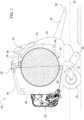
FIG. 1 is a schematic side view of a round baler implement. -
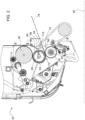
FIG. 2 is a schematic cross sectional partial side view of a wrap system of the round baler implement. -
FIG. 3 is a schematic and enlarged cross sectional partial side view of the wrap system showing an ejection trajectory of a wrap material. -
FIG. 4 is a schematic and enlarged perspective view of the wrap system. -
FIG. 5 is a schematic perspective view of a scraper of the wrap system. -
FIG. 6 is a schematic plan view of the scraper. - Those having ordinary skill in the art will recognize that terms such as "above," "below," "upward," "downward," "top," "bottom," etc., are used descriptively for the figures, and do not represent limitations on the scope of the disclosure, as defined by the appended claims. Furthermore, the teachings may be described herein in terms of functional and/or logical block components and/or various processing steps. It should be realized that such block components may be comprised of any number of hardware, software, and/or firmware components configured to perform the specified functions.
- Terms of degree, such as "generally", "substantially" or "approximately" are understood by those of ordinary skill to refer to reasonable ranges outside of a given value or orientation, for example, general tolerances or positional relationships associated with manufacturing, assembly, and use of the described embodiments.
- As used herein, "e.g." is utilized to non-exhaustively list examples, and carries the same meaning as alternative illustrative phrases such as "including," "including, but not limited to," and "including without limitation." As used herein, unless otherwise limited or modified, lists with elements that are separated by conjunctive terms (e.g., "and") and that are also preceded by the phrase "one or more of," "at least one of," "at least," or a like phrase, indicate configurations or arrangements that potentially include individual elements of the list, or any combination thereof. For example, "at least one of A, B, and C" and "one or more of A, B, and C" each indicate the possibility of only A, only B, only C, or any combination of two or more of A, B, and C (A and B; A and C; B and C; or A, B, and C). As used herein, the singular forms "a", "an" and "the" are intended to include the plural forms as well, unless the context clearly indicates otherwise. Further, "comprises," "includes," and like phrases are intended to specify the presence of stated features, steps, operations, elements, and/or components, but do not preclude the presence or addition of one or more other features, steps, operations, elements, components, and/or groups thereof.
- Referring to the Figures, wherein like numerals indicate like parts throughout the several views, a baler implement is generally shown at 20. Referring to
FIG. 1 , thebaler implement 20 includes aframe 22. One or moreground engaging elements 24, such as but not limited to one or more wheels and/or tracks, are attached to and rotatably supported by theframe 22. Atongue 26 may be coupled to theframe 22 at a forward end of theframe 22. Ahitch arrangement 28 may be included with thetongue 26. Thehitch arrangement 28 may be used to attach the baler implement 20 to a traction unit, such as but not limited to an agricultural tractor. In other embodiments, the baler implement 20 may be self-propelled, in which case the traction unit and the baler implement 20 are configured as a single, self-propelled vehicle. - The baler implement 20 includes a
baling system 32. The balingsystem 32 forms a balingchamber 34. The balingsystem 32 is attached to and supported by theframe 22. The balingsystem 32 may include one or more walls or panel 88s that at least partially enclose and/or define the balingchamber 34. In the example implementation shown in the Figures and described herein, the baler implement 20 further includes agate 36. Thegate 36 is attached to and rotatably supported by theframe 22. Thegate 36 is positioned adjacent a rearward end of theframe 22 and is pivotably moveable about agate axis 38. Thegate axis 38 is generally horizontal and perpendicular to a centrallongitudinal axis 40 of theframe 22. Thegate 36 is moveable between a closed position for forming a bale within the balingchamber 34, and an open position for discharging the bale from the balingchamber 34. - The baler implement 20 includes a pick-
up 42 disposed proximate the forward end of theframe 22. The pickup gathers crop material from a ground surface and directs the gathered crop material toward and into aninlet 44 of the balingchamber 34. The pickup may include, but is not limited to tines, forks, augers, conveyors, baffles, etc., for gathering and moving the crop material. The baler implement 20 may be equipped with a pre-cutter, disposed between the pickup and theinlet 44. As such, the pre-cutter is disposed downstream of the pickup and upstream of theinlet 44 relative to a direction of travel of the crop material. The pre-cutter cuts or chops the crop material into smaller pieces. - The baler implement 20 may be configured as a variable chamber baler, or as a fixed chamber baler. The example implementation of the baler implement 20 shown in the Figures and described herein is depicted and described as a variable chamber baler. As is understood by those skilled in the art, the variable chamber baler includes a plurality of longitudinally extending side-by-
side forming belts 46 that are supported by a plurality ofrollers 48. The bale is formed by the formingbelts 46 and one or more side walls of the housing. - The crop material is directed through the
inlet 44 and into the balingchamber 34, whereby the formingbelts 46 roll the crop material in a spiral fashion into the bale having a cylindrical shape. The formingbelts 46 apply a constant pressure to the crop material as the crop material is formed into the bale. A formingbelt tensioner 50 continuously moves the formingbelts 46 radially outward relative to a center of the cylindrical bale as the diameter of the bale increases. The formingbelt tensioner 50 maintains the appropriate tension in the formingbelts 46 to obtain the desired density of the crop material. - The baler implement 20 includes a
wrap system 52. Thewrap system 52 is operable to wrap the bale with awrap material 54 inside the balingchamber 34. Once the bale is formed to a desired size, thewrap system 52 is initiated to begin a wrap cycle. Referring toFIGS. 2-3 , when a wrap cycle is initiated thewrap system 52 feeds or inserts thewrap material 54 through theinlet 44 and into the balingchamber 34 to wrap the bale and thereby secure the crop material in a tight package and maintain the desired shape of the bale. Thewrap material 54 may include, but is not limited to, a net mesh or a solid plastic wrap. Movement of thegate 36 into the open position simultaneously moves the formingbelts 46 clear of the formed bale and allows the formed and wrapped bale to be discharged through the rear of the balingchamber 34. - Referring to
FIGS. 2-3 , thewrap system 52 includes a pair ofspool rollers spool rollers first spool roller 56 and asecond spool roller 58. Thefirst spool roller 56 and thesecond spool roller 58 are arranged in a parallel relationship, and extend transversely across a width of theframe 22 in a horizontal orientation, generally perpendicular to the centrallongitudinal axis 40 of theframe 22. - The
first spool roller 56 includes a cylindrical shape having a respective centerline, about which thefirst spool roller 56 rotates. As such, the respective centerline of thefirst spool roller 56 is an axis ofrotation 60 of thefirst spool roller 56. Thesecond spool roller 58 includes a cylindrical shape having a respective centerline, about which thesecond spool roller 58 rotates. As such, the respective centerline of thesecond spool roller 58 is an axis ofrotation 62 of thesecond spool roller 58. Thefirst spool roller 56 and thesecond spool roller 58 are arranged such that an exteriorcircumferential surface 64 of thefirst spool roller 56 and an exteriorcircumferential surface 66 of thesecond spool roller 58 are disposed in contacting or abutting engagement, and form a nip 68 therebetween where their respective exteriorcircumferential surfaces first spool roller 56 and thesecond spool roller 58 come together and contact each other. - As described above, the pair of
spool rollers first spool roller 56 and thesecond spool roller 58 rotate in opposite rotational directions relative to each other and receive thewrap material 54 from asupply roll 30 through anentrance side 70 of thenip 68 and discharge thewrap material 54 toward theinlet 44 of the balingchamber 34 through anoutlet side 72 of thenip 68. As shown in the example implementation of the Figures, thefirst spool roller 56 is rotatable about its' respective axis ofrotation 60 in acounter-clockwise direction 74 as viewed on the page of the drawing, and thesecond spool roller 58 is rotatable about its' respective axis ofrotation 62 in aclockwise direction 76 as viewed on the page of the drawing. As such, thefirst spool roller 56 and thesecond spool roller 58 cooperate to feed thewrap material 54 through thenip 68, from left (entrance side 70 of the nip 68) to right (outlet side 72 of the nip 68) as viewed on the page of the drawing. - The
first spool roller 56 may include an elastomer defining the exteriorcircumferential surface 64 of thefirst spool roller 56. The elastomer exhibits static adhesion or "sticky" properties which limits movement of thewrap material 54 relative to the exteriorcircumferential surface 64 of thefirst spool roller 56. The elastomer may include for example, but is not limited to, a natural or synthetic rubber material, a rubber-like material, or some other material having similar static adhesion properties. - The
second spool roller 58 may also include an elastomer defining the exteriorcircumferential surface 66 of thesecond spool roller 58. The elastomer exhibits static adhesion or "sticky" properties which limits movement of thewrap material 54 relative to the exteriorcircumferential surface 66 of thesecond spool roller 58. The elastomer may include for example, but is not limited to, a natural or synthetic rubber material, a rubber-like material, or some other material having similar static adhesion properties. - As shown in
FIGS. 2-3 , thewrap material 54 follows a routing path that partially encircles thefirst spool roller 56 about the axis ofrotation 60 of thefirst spool roller 56. The routing path follows a counter-clockwise path around the exteriorcircumferential surface 64 of thefirst spool roller 56 as viewed on the page of the drawing. Thewrap material 54 enters thenip 68 moving from left to right as viewed on the page of the drawing, whereby thewrap material 54 is grasped between thefirst spool roller 56 and thesecond spool roller 58 at thenip 68. During a wrap cycle, thefirst spool roller 56 and thesecond spool roller 58 are counter rotated bout their respective axes of rotation to eject thewrap material 54 from thenip 68 toward and through theinlet 44 and into the balingchamber 34. - An ejection trajectory is the trajectory or path that a leading edge of the
wrap material 54 follows when ejected from thenip 68 and prior to entering or passing through theinlet 44 into the balingchamber 34. The ejection trajectory may be described relative to atangent line 78 of thenip 68. As described above, thenip 68 is the contact location where the exteriorcircumferential surface 64 of thefirst spool roller 56 contacts the exteriorcircumferential surface 66 of thesecond spool roller 58. Thetangent line 78 of thenip 68 is therefore the tangent of a contact point between the exteriorcircumferential surface 64 of thefirst spool roller 56 and the exteriorcircumferential surface 66 of thesecond spool roller 58 at thenip 68, and generally extends along the centrallongitudinal axis 40 of theframe 22.Wrap material 54 discharged from thenip 68 within an allowable angular range above and below thetangent line 78 of the nip 68 should properly enter theinlet 44 of the balingchamber 34. However, occasionally, thewrap material 54 may fail to separate from thefirst spool roller 56 and/or separate from thefirst spool roller 56 outside of the allowable angular range. - In order to prevent the
wrap material 54 from being wrapped completely around thefirst spool roller 56 and to help guide thewrap material 54 into theinlet 44 when thewrap material 54 fails to separate from thefirst spool roller 56 within the allowable angular range of thetangent line 78 of thenip 68, the baler implement 20 may include ascraper 80. - Referring to
FIGS. 2-3 , thescraper 80 is positioned on theoutlet side 72 of thenip 68, adjacent to thefirst spool roller 56. Thescraper 80 is configured for guiding thewrap material 54 away from the circumferential exterior surface of thefirst spool roller 56. Referring toFIGS. 3-6 , thescraper 80 includes abody 82. Thebody 82 extends along alongitudinal axis 84 in a generally parallel relationship relative to thefirst spool roller 56. As such, thebody 82 of thescraper 80 extends generally across a width of the baler implement 20, on a generally horizontal plane and generally perpendicular to the centrallongitudinal axis 40 of theframe 22. - The
body 82 includes a mountingportion 86 and apanel 88. The mountingportion 86 is configured for attachment to a structural component of the baler implement 20. The mountingportion 86 supports thepanel 88 in a position relative to thefirst spool roller 56. The mountingportion 86 may include any structural shape suitable to mount thescraper 80 to the baler implement 20. As shown in the Figures, the example implementation of the mountingportion 86 of thescraper 80 is configured as a generally planar sheet portion that is secured to the baler implement 20 by one or more fasteners, e.g., bolts or other similar devices. However, it should be appreciated that the mountingportion 86 of thescraper 80 may differ from the example implementation shown in the Figures and may be attached and/or secured to the baler implement 20 using some other attaching process, such as welding or some other mechanical fastening system. - The
panel 88 extends from the mountingportion 86 of thescraper 80 to a distal edge of thepanel 88. Thepanel 88 is formed from a generally thin, planar structure. The distal edge of thepanel 88 may be cantilevered from the mountingportion 86 of thescraper 80. Thepanel 88 extends in a generally parallel relationship relative to thefirst spool roller 56. Thepanel 88 may include and/or be manufactured from a resilient material. The resilient material may include a material that enables thepanel 88 to flex or bend away from an original or initial shape, and then return back to that original or initial shape. For example, the resilient material may include, but is not limited to, one of a metal such as but not limited to a steel material, or a spring steel material, or a plastic/polymer material. - As best shown in
FIG. 6 , the distal edge of thepanel 88 includes and/or defines an undulatingedge 90 of thescraper 80. The undulatingedge 90 of thescraper 80 includes a plurality ofpeaks 92 and a plurality ofvalleys 94 cooperating to define a plurality offingers 96. Thepeaks 92 and thevalleys 94 of the undulatingedge 90 may be arranged in an alternating sequence in which each one of thevalleys 94 is disposed between a respective pair ofadjacent peaks 92. Each respective one of thepeaks 92 and thevalleys 94 may include a transitional shape disposed at their respective vertices. The transitional shape may include, but are not limited to, a generally rounded shape, such as shown in the figures, or a sharper more crisply defined pointed intersection, e.g., a V-shape. It should be appreciated that thepeaks 92 and thevalleys 94 may include some other transitional shape other than that shown in the Figures or described herein. - Each respective pair of the
adjacent peaks 92 define a peak-to-peak distance 98 therebetween. The peak-to-peak distance 98 may vary between different pairs of thepeaks 92. In other implementations, the peak-to-peak distance 98 may be substantially identical between different pairs of thepeaks 92. In one implementation, the peak-to-peak distance 98 may be between the range of five millimeters (5 mm) and two hundred millimeters (200 mm), and more particularly between the range of ten millimeters (10 mm) and one hundred millimeters (100 mm). However, it should be appreciated that the peak-to-peak distance 98 may vary from the example range described herein. - The undulating
edge 90 of thescraper 80 further includes and/or defines afinger depth 100. Thefinger depth 100 is the perpendicular distance measured between an apex 102 of a respective one of thepeaks 92, i.e.,fingers 96, and aroot 104 of anadjacent valley 94. In one implementation, thefinger depth 100 for each respective one of thefingers 96 may differ. In other implementations, thefinger depth 100 for each respective one of thefingers 96 may be substantially identical. In one implementation, thefinger depth 100 for eachfinger 96 may be between the range of two millimeters (2 mm) and one hundred millimeters (100 mm). In one example implementation, thefinger depth 100 for eachfinger 96 is at least equal to or greater than approximately 3 mm. However, it should be appreciated that thefinger depth 100 may vary from the example range described herein. - Referring to
FIG. 6 , the undulatingedge 90 of thescraper 80 extends along thefirst spool roller 56 and includes anedge length 106. Theedge length 106 may be defined as the length of the undulatingedge 90 measured along the axis ofrotation 60 of thefirst spool roller 56. In one implementation, theedge length 106 may be equal to or greater than one half aroller length 108 of thefirst spool roller 56. Theroller length 108 may be defined as the length of thefirst spool roller 56 measured along the axis ofrotation 60 of thefirst spool roller 56. As such, in one implementation, theedge length 106 of thescraper 80 may be greater than one half theroller length 108 of thefirst spool roller 56. In one implementation, theedge length 106 of thescraper 80 may be substantially equal to theroller length 108 of thefirst spool roller 56. However, it should be appreciated that in other embodiments, theedge length 106 of thescraper 80 may be less than one half of theroller length 108 of thefirst spool roller 56. - Referring to
FIG. 3 , thepanel 88 positions the undulatingedge 90 of thescraper 80 relative to thefirst spool roller 56 such that the plurality ofpeaks 92 are positioned proximate to the circumferential exterior surface of thefirst spool roller 56. In one implementation, thepanel 88 may be arranged to present the plurality ofpeaks 92 of the undulatingedge 90 in a generally tangential relationship relative to the circumferential exterior surface of thefirst spool roller 56. In another implementation, thepanel 88 may be arranged to position the plurality ofpeaks 92 of the undulating edge 90 aseparation distance 110 measured from thetangent line 78 passing through thenip 68 between thefirst spool roller 56 and thesecond spool roller 58. Theseparation distance 110 may be equal to or greater than five millimeters (5 mm). In one particular implementation, theseparation distance 110 is approximately equal to fifteen millimeters (15 mm). However, it should be appreciated that theseparation distance 110 may vary from the example values described herein. - It should be appreciated that the
panel 88 may position the undulatingedge 90 of thescraper 80 such that thepeaks 92 of the undulatingedge 90 are both spaced from thetangent line 78 of thenip 68 at the desiredseparation distance 110 and with thepeaks 92 positioned in a generally tangential relationship relative to the exteriorcircumferential surface 64 of thefirst spool roller 56. It should be appreciated that changing theseparation distance 110 may affect the angular relationship between the undulatingedge 90 and the exteriorcircumferential surface 64 of thefirst spool roller 56. As such, changes to theseparation distance 110 may require a corresponding change to the angular position of thepanel 88 relative to the exteriorcircumferential surface 64 of thefirst spool roller 56 to maintain the generally tangential relationship therebetween. - In one implementation, the
panel 88 may be arranged to position the plurality ofpeaks 92 of the undulating edge 90 a firstorthogonal distance 112 measured from the circumferential exterior surface of thefirst spool roller 56. The firstorthogonal distance 112 may be between the range of one millimeter (1.0 mm) and eight millimeters (8.0 mm). However, it should be appreciated that the value of the firstorthogonal distance 112 may vary from the example range provided herein. Thepanel 88 may be arranged to position the plurality ofvalleys 94 of the undulating edge 90 a secondorthogonal distance 114 from the circumferential exterior surface of thefirst spool roller 56. In some implementations, the firstorthogonal distance 112 may be less than the secondorthogonal distance 114. - The detailed description and the drawings or figures are supportive and descriptive of the disclosure, but the scope of the disclosure is defined solely by the claims. While some of the best modes and other embodiments for carrying out the claimed teachings have been described in detail, various alternative designs and embodiments exist for practicing the disclosure defined in the appended claims.
Claims (15)
- A baler implement (20) comprising:a baling system (32) defining a baling chamber (34) having an inlet (44) into the baling chamber (34), wherein the baling system (32) is operable to receive crop material into the baling chamber (34) through the inlet (44) and form the crop material into a bale within the baling chamber (34);a wrap system (52) operable to insert a wrap material (54) through the inlet (44) and into the baling chamber (34) to wrap the bale, the wrap system (52) including:a first spool roller (56) and a second spool roller (58) arranged in parallel and positioned to form a nip (68) therebetween, wherein the first spool roller (56) and the second spool roller (58) are configured to receive the wrap material (54) from a supply roll (30) through an entrance side (70) of the nip (68) and discharge the wrap material (54) toward the inlet (44) of the baling chamber (34) through an outlet side (72) of the nip (68);a scraper (80) positioned on the outlet side (72) of the nip (68) adjacent to the first spool roller (56) for guiding the wrap material (54) away from a circumferential exterior surface of the first spool roller (56); andwherein the scraper (80) includes an undulating edge (90) defining a plurality of peaks (92) and a plurality of valleys (94) with the plurality of peaks (92) positioned proximate to the circumferential exterior surface of the first spool roller (56).
- The baler implement (20) set forth in claim 1, wherein the scraper (80) includes a panel (88) extending parallel with the first spool roller (56) and defining the undulating edge (90) of the scraper (80).
- The baler implement (20) set forth in claim 1 or 2, wherein the panel (88) is arranged to position the plurality of peaks (92) of the undulating edge (90) a separation distance (110) measured from a tangent line (78) passing through the nip (68) between the first spool roller (56) and the second spool roller (58).
- The baler implement (20) according to at least one of the preceding claims, wherein the separation distance (110) is equal to or greater than ten millimeters.
- The baler implement (20) according to at least one of the preceding claims, wherein the panel (88) is arranged to position the plurality of peaks (92) of the undulating edge (90) a first orthogonal distance (112) from the circumferential exterior surface of the first spool roller (56).
- The baler implement (20) according to at least one of the preceding claims, wherein the panel (88) is arranged to position the plurality of valleys (94) of the undulating edge (90) a second orthogonal distance (114) from the circumferential exterior surface of the first spool roller (56), wherein the first orthogonal distance (112) is less than the second orthogonal distance (114).
- The baler implement (20) according to at least one of the preceding claims, wherein the panel (88) includes a resilient material.
- The baler implement (20) according to at least one of the preceding claims, wherein the resilient material is one of a steel or a plastic.
- The baler implement (20) according to at least one of the preceding claims, wherein the plurality of peaks (92) and the plurality of valleys (94) are arranged in an alternating sequence in which each one of the plurality of valleys (94) is disposed between a respective pair of adjacent peaks (92) of the plurality of peaks (92).
- The baler implement (20) according to at least one of the preceding claims, wherein each respective pair of the adjacent peaks (92) define a peak-to-peak distance (98) therebetween that is between the range of ten millimeters and one hundred millimeters.
- The baler implement (20) according to at least one of the preceding claims, wherein the undulating edge (90) includes an edge length (106) that is equal to or greater than one half a roller length (108) of the first spool roller (56) along a respective axis of rotation (60) of the first spool roller (56).
- The baler implement (20) according to at least one of the preceding claims, wherein the edge length (106) of the undulating edge (90) is substantially equal to the roller length (108) of the first spool roller (56).
- The baler implement (20) according to at least one of the preceding claims, wherein the first spool roller (56) includes an elastic material forming the exterior circumferential surface thereof.
- The baler implement (20) according to at least one of the preceding claims, wherein the first spool roller (56) and the second spool roller (58) are configured to rotate about respective axes of rotation in opposite rotational directions relative to each other.
- The baler implement (20) according to at least one of the preceding claims, wherein the undulating edge (90) defines a finger depth (100) measured perpendicularly relative to and between an apex (102) of a respective one of the plurality of peaks (92) and a root (104) of a respective adjacent one of the plurality of valleys (94), wherein the finger depth (100) is equal to or greater than three millimeters.
Applications Claiming Priority (1)
| Application Number | Priority Date | Filing Date | Title |
|---|---|---|---|
| US18/297,668 US12439858B2 (en) | 2023-04-10 | 2023-04-10 | Round baler implement with net scraper |
Publications (2)
| Publication Number | Publication Date |
|---|---|
| EP4445720A1 true EP4445720A1 (en) | 2024-10-16 |
| EP4445720B1 EP4445720B1 (en) | 2025-12-31 |
Family
ID=90364728
Family Applications (1)
| Application Number | Title | Priority Date | Filing Date |
|---|---|---|---|
| EP24162533.4A Active EP4445720B1 (en) | 2023-04-10 | 2024-03-11 | ROUND BALE PRESS WITH NET WIPER |
Country Status (2)
| Country | Link |
|---|---|
| US (1) | US12439858B2 (en) |
| EP (1) | EP4445720B1 (en) |
Citations (6)
| Publication number | Priority date | Publication date | Assignee | Title |
|---|---|---|---|---|
| US4581879A (en) * | 1984-02-15 | 1986-04-15 | Deere & Company | Anti-wrap attachment for rolls of baling machine |
| US5557906A (en) * | 1994-07-22 | 1996-09-24 | Deere & Company | Pivotable guide pan for round bale wrapping material |
| FR2775157B1 (en) * | 1998-02-26 | 2000-04-28 | Gallignani Spa | ROUND BALL PRESS COMPRISING A BELT DRIVE OR DRIVE BELT PROVIDED WITH A SCRAPER |
| US9010071B2 (en) * | 2009-08-10 | 2015-04-21 | Cnh Industrial America Llc | Baler with an improved stripper roll |
| US20190014725A1 (en) * | 2017-07-12 | 2019-01-17 | Deere & Company | Round baler |
| EP4151076A1 (en) * | 2021-09-15 | 2023-03-22 | Deere & Company | Bale wrapping system with proportional cycle acceleration |
Family Cites Families (6)
| Publication number | Priority date | Publication date | Assignee | Title |
|---|---|---|---|---|
| US5216873A (en) * | 1991-10-07 | 1993-06-08 | Hay & Forage Industries | Wrapper cutoff mechanism for round balers |
| US5319899A (en) * | 1992-08-14 | 1994-06-14 | Ford New Holland Inc. | Net severing apparatus for round baler |
| US5448873A (en) * | 1993-02-05 | 1995-09-12 | New Holland North America, Inc. | Net knife for round baler |
| NZ313974A (en) * | 1995-08-10 | 1999-10-28 | Kurt Ertbolle Madsen | A method and a unit for producing round bales of straw or of like material with film wrapping |
| GB201417296D0 (en) * | 2014-09-30 | 2014-11-12 | Tube Line Mfg Ltd | Film cutter for hay-bale wrapper |
| NL2014395B1 (en) * | 2015-03-04 | 2016-10-13 | Forage Innovations Bv | Bale forming and wrapping apparatus and method with a moveable wrapping material conveyer. |
-
2023
- 2023-04-10 US US18/297,668 patent/US12439858B2/en active Active
-
2024
- 2024-03-11 EP EP24162533.4A patent/EP4445720B1/en active Active
Patent Citations (6)
| Publication number | Priority date | Publication date | Assignee | Title |
|---|---|---|---|---|
| US4581879A (en) * | 1984-02-15 | 1986-04-15 | Deere & Company | Anti-wrap attachment for rolls of baling machine |
| US5557906A (en) * | 1994-07-22 | 1996-09-24 | Deere & Company | Pivotable guide pan for round bale wrapping material |
| FR2775157B1 (en) * | 1998-02-26 | 2000-04-28 | Gallignani Spa | ROUND BALL PRESS COMPRISING A BELT DRIVE OR DRIVE BELT PROVIDED WITH A SCRAPER |
| US9010071B2 (en) * | 2009-08-10 | 2015-04-21 | Cnh Industrial America Llc | Baler with an improved stripper roll |
| US20190014725A1 (en) * | 2017-07-12 | 2019-01-17 | Deere & Company | Round baler |
| EP4151076A1 (en) * | 2021-09-15 | 2023-03-22 | Deere & Company | Bale wrapping system with proportional cycle acceleration |
Also Published As
| Publication number | Publication date |
|---|---|
| US12439858B2 (en) | 2025-10-14 |
| US20240334880A1 (en) | 2024-10-10 |
| EP4445720B1 (en) | 2025-12-31 |
Similar Documents
| Publication | Publication Date | Title |
|---|---|---|
| CN106233944B (en) | Module wrapping material guiding device | |
| US7694504B1 (en) | Secondary feeder rotor behind undershot precutter | |
| CA1326787C (en) | Round baler with variable bale chamber | |
| EP0965263B1 (en) | Round bale wrapping apparatus | |
| EP0954959B1 (en) | Round bale forming apparatus | |
| US6874311B2 (en) | Crop recovery machine | |
| US8522512B2 (en) | Round baler having a web wrap apparatus | |
| EP4151076B1 (en) | Bale wrapping system with proportional cycle acceleration | |
| CA2372830A1 (en) | Crop deflector for machine for mowing stalk-like crops | |
| US5191833A (en) | Roll stripping apparatus for round baler | |
| CN111246726A (en) | Attachable lug for corn collection belt | |
| US5097760A (en) | Powered trash removal apparatus for round baler | |
| US12439858B2 (en) | Round baler implement with net scraper | |
| US5327823A (en) | Splice for round baler belts | |
| EP0252458B1 (en) | Machine for forming a cylindrical bale of crop | |
| US5913805A (en) | Trash baffle for round baler apparatus | |
| EP4108068B1 (en) | Net guide for upper rollers of round baler | |
| EP0339730B1 (en) | Round baler with variable bale chamber and sledge assembly | |
| EP0745319A1 (en) | A harvesting machine | |
| US6094899A (en) | Separating arrangement for adjacent belts in a round baler | |
| EP4717075A1 (en) | Wrap material guide for spool roller of a baler implement | |
| EP3771326B1 (en) | Build-up resistant crop conveyor systems for agricultural machines | |
| EP3964047B1 (en) | Crop stop for bale roll | |
| US10820524B2 (en) | Wrapping device and round baler | |
| US12527260B2 (en) | Agricultural vehicle with tine support guides that limit deflection of a tine |
Legal Events
| Date | Code | Title | Description |
|---|---|---|---|
| PUAI | Public reference made under article 153(3) epc to a published international application that has entered the european phase |
Free format text: ORIGINAL CODE: 0009012 |
|
| STAA | Information on the status of an ep patent application or granted ep patent |
Free format text: STATUS: THE APPLICATION HAS BEEN PUBLISHED |
|
| AK | Designated contracting states |
Kind code of ref document: A1 Designated state(s): AL AT BE BG CH CY CZ DE DK EE ES FI FR GB GR HR HU IE IS IT LI LT LU LV MC ME MK MT NL NO PL PT RO RS SE SI SK SM TR |
|
| STAA | Information on the status of an ep patent application or granted ep patent |
Free format text: STATUS: REQUEST FOR EXAMINATION WAS MADE |
|
| 17P | Request for examination filed |
Effective date: 20250416 |
|
| GRAP | Despatch of communication of intention to grant a patent |
Free format text: ORIGINAL CODE: EPIDOSNIGR1 |
|
| STAA | Information on the status of an ep patent application or granted ep patent |
Free format text: STATUS: GRANT OF PATENT IS INTENDED |
|
| INTG | Intention to grant announced |
Effective date: 20250911 |
|
| GRAS | Grant fee paid |
Free format text: ORIGINAL CODE: EPIDOSNIGR3 |
|
| GRAA | (expected) grant |
Free format text: ORIGINAL CODE: 0009210 |
|
| STAA | Information on the status of an ep patent application or granted ep patent |
Free format text: STATUS: THE PATENT HAS BEEN GRANTED |
|
| AK | Designated contracting states |
Kind code of ref document: B1 Designated state(s): AL AT BE BG CH CY CZ DE DK EE ES FI FR GB GR HR HU IE IS IT LI LT LU LV MC ME MK MT NL NO PL PT RO RS SE SI SK SM TR |
|
| REG | Reference to a national code |
Ref country code: CH Ref legal event code: F10 Free format text: ST27 STATUS EVENT CODE: U-0-0-F10-F00 (AS PROVIDED BY THE NATIONAL OFFICE) Effective date: 20251231 Ref country code: GB Ref legal event code: FG4D |
|
| REG | Reference to a national code |
Ref country code: DE Ref legal event code: R096 Ref document number: 602024001866 Country of ref document: DE |
|
| REG | Reference to a national code |
Ref country code: IE Ref legal event code: FG4D |
|
| REG | Reference to a national code |
Ref country code: LT Ref legal event code: MG9D |
|
| PG25 | Lapsed in a contracting state [announced via postgrant information from national office to epo] |
Ref country code: NO Free format text: LAPSE BECAUSE OF FAILURE TO SUBMIT A TRANSLATION OF THE DESCRIPTION OR TO PAY THE FEE WITHIN THE PRESCRIBED TIME-LIMIT Effective date: 20260331 |
|
| PGFP | Annual fee paid to national office [announced via postgrant information from national office to epo] |
Ref country code: DE Payment date: 20260219 Year of fee payment: 3 |
|
| PG25 | Lapsed in a contracting state [announced via postgrant information from national office to epo] |
Ref country code: HR Free format text: LAPSE BECAUSE OF FAILURE TO SUBMIT A TRANSLATION OF THE DESCRIPTION OR TO PAY THE FEE WITHIN THE PRESCRIBED TIME-LIMIT Effective date: 20251231 Ref country code: FI Free format text: LAPSE BECAUSE OF FAILURE TO SUBMIT A TRANSLATION OF THE DESCRIPTION OR TO PAY THE FEE WITHIN THE PRESCRIBED TIME-LIMIT Effective date: 20251231 |
|
| PGFP | Annual fee paid to national office [announced via postgrant information from national office to epo] |
Ref country code: AT Payment date: 20260301 Year of fee payment: 3 |
|
| PG25 | Lapsed in a contracting state [announced via postgrant information from national office to epo] |
Ref country code: RS Free format text: LAPSE BECAUSE OF FAILURE TO SUBMIT A TRANSLATION OF THE DESCRIPTION OR TO PAY THE FEE WITHIN THE PRESCRIBED TIME-LIMIT Effective date: 20260331 |
|
| PGFP | Annual fee paid to national office [announced via postgrant information from national office to epo] |
Ref country code: FR Payment date: 20260325 Year of fee payment: 3 |
|
| PG25 | Lapsed in a contracting state [announced via postgrant information from national office to epo] |
Ref country code: LV Free format text: LAPSE BECAUSE OF FAILURE TO SUBMIT A TRANSLATION OF THE DESCRIPTION OR TO PAY THE FEE WITHIN THE PRESCRIBED TIME-LIMIT Effective date: 20251231 |
|
| PG25 | Lapsed in a contracting state [announced via postgrant information from national office to epo] |
Ref country code: BG Free format text: LAPSE BECAUSE OF FAILURE TO SUBMIT A TRANSLATION OF THE DESCRIPTION OR TO PAY THE FEE WITHIN THE PRESCRIBED TIME-LIMIT Effective date: 20251231 |
|
| REG | Reference to a national code |
Ref country code: NL Ref legal event code: MP Effective date: 20251231 |