EP4445717A1 - Straw chopper for combine harvester - Google Patents
Straw chopper for combine harvester Download PDFInfo
- Publication number
- EP4445717A1 EP4445717A1 EP24167760.8A EP24167760A EP4445717A1 EP 4445717 A1 EP4445717 A1 EP 4445717A1 EP 24167760 A EP24167760 A EP 24167760A EP 4445717 A1 EP4445717 A1 EP 4445717A1
- Authority
- EP
- European Patent Office
- Prior art keywords
- blade
- blade shaft
- counterknife
- residue
- outer face
- Prior art date
- Legal status (The legal status is an assumption and is not a legal conclusion. Google has not performed a legal analysis and makes no representation as to the accuracy of the status listed.)
- Granted
Links
Images





Classifications
-
- A—HUMAN NECESSITIES
- A01—AGRICULTURE; FORESTRY; ANIMAL HUSBANDRY; HUNTING; TRAPPING; FISHING
- A01F—PROCESSING OF HARVESTED PRODUCE; HAY OR STRAW PRESSES; DEVICES FOR STORING AGRICULTURAL OR HORTICULTURAL PRODUCE
- A01F12/00—Parts or details of threshing apparatus
- A01F12/40—Arrangements of straw crushers or cutters
-
- A—HUMAN NECESSITIES
- A01—AGRICULTURE; FORESTRY; ANIMAL HUSBANDRY; HUNTING; TRAPPING; FISHING
- A01D—HARVESTING; MOWING
- A01D90/00—Vehicles for carrying harvested crops with means for selfloading or unloading
- A01D90/02—Loading means
- A01D90/04—Loading means with additional cutting means
-
- A—HUMAN NECESSITIES
- A01—AGRICULTURE; FORESTRY; ANIMAL HUSBANDRY; HUNTING; TRAPPING; FISHING
- A01F—PROCESSING OF HARVESTED PRODUCE; HAY OR STRAW PRESSES; DEVICES FOR STORING AGRICULTURAL OR HORTICULTURAL PRODUCE
- A01F29/00—Cutting apparatus specially adapted for cutting hay, straw or the like
- A01F29/02—Cutting apparatus specially adapted for cutting hay, straw or the like having rotating knives with their cutting edges in a plane perpendicular to their rotational axis
- A01F29/04—Cutting apparatus specially adapted for cutting hay, straw or the like having rotating knives with their cutting edges in a plane perpendicular to their rotational axis with feeding direction transverse to axis
-
- A—HUMAN NECESSITIES
- A01—AGRICULTURE; FORESTRY; ANIMAL HUSBANDRY; HUNTING; TRAPPING; FISHING
- A01F—PROCESSING OF HARVESTED PRODUCE; HAY OR STRAW PRESSES; DEVICES FOR STORING AGRICULTURAL OR HORTICULTURAL PRODUCE
- A01F29/00—Cutting apparatus specially adapted for cutting hay, straw or the like
- A01F29/09—Details
- A01F29/095—Mounting or adjusting of knives
-
- A—HUMAN NECESSITIES
- A01—AGRICULTURE; FORESTRY; ANIMAL HUSBANDRY; HUNTING; TRAPPING; FISHING
- A01F—PROCESSING OF HARVESTED PRODUCE; HAY OR STRAW PRESSES; DEVICES FOR STORING AGRICULTURAL OR HORTICULTURAL PRODUCE
- A01F29/00—Cutting apparatus specially adapted for cutting hay, straw or the like
- A01F29/09—Details
- A01F29/16—Safety devices, e.g. emergency brake arrangements
Definitions
- Agricultural machines such as combine harvesters, typically process crop material, and deposit a portion of the material on the ground behind the machine.
- the material that is deposited is primarily material other than grain (“MoG”), such as chaff and stalks. This is commonly called “residue.”
- MoG material other than grain
- the machine may include a chopper to reduce the residue size, and a spreader to distribute the residue.
- the chopper typically comprises a series of knives that rotate on a shaft and are partially enclosed by a shroud. The residue enters the shroud, and the knives strike and cut the residue.
- a typical chopper also has counterknives that extend radially towards the shaft, and between adjacent pairs of the rotating knives. The counterknives face towards the incoming stream of residue, and provide additional cutting edges.
- the counterknives can be mounted on their own shaft or on a support that can be moved to extend and retract the counterknives.
- the counterknives enter the chopper housing through slots, and residue can enter these slots. As the residue accumulates, it can inhibit the movement and operation of the counterknives.
- the inventors have found that further improvements to counterknives can benefit the art.
- a residue counterknife assembly comprising: a blade mount configured to secure to a blade shaft having a rotation axis; one or more blades secured to the blade mount and extending away from the rotation axis; and at least one blocking surface comprising an at least semicircular outer face located concentric to and at least partially surrounding the rotation axis.
- a residue counterknife system for use on an agricultural harvester.
- the residue counterknife system comprises: a blade shaft extending along a blade shaft direction; a chopper pan extending parallel to the blade shaft direction and comprising a plurality of blade slots spaced along the blade shaft direction; at least two blade shaft supports spaced apart along the blade shaft direction, wherein the at least two blade shaft supports are configured to rotatably support the blade shaft to rotate about a rotation axis that is parallel to the blade shaft direction, through a range of motion between an extended position and a retracted position; and a plurality of counterknife assemblies attached to the blade shaft along the blade shaft direction.
- Each counterknife assembly comprises: a blade mount, one or more blades secured to the blade mount and extending away from the rotation axis, wherein each blade is positioned to extend through a respective one of the blade slots at least when the blade shaft is in the extended position, and at least one blocking surface comprising an at least semicircular outer face located concentric to and at least partially surrounding the rotation axis, wherein a portion of the blocking surface passes through a respective predetermined point relative to a respective one of the blade slots throughout the range of motion of the blade shaft between the extended position and the retracted position.
- an agricultural harvester machine comprising: a chassis configured for movement on a surface; and a residue chopper comprising: a housing defining a cutting chamber, a cutting knife assembly mounted in the cutting chamber to rotate about a cutting knife rotation axis, a blade shaft located outside the housing and extending along a blade shaft direction that is parallel to the cutting knife rotation axis, a chopper pan extending parallel to the blade shaft direction and defining a portion of the housing defining the cutting chamber, the chopper pan comprising a plurality of blade slots spaced along the blade shaft direction, at least two blade shaft supports spaced apart along the blade shaft direction, wherein the at least two blade shaft supports are configured to rotatably support the blade shaft to the chopper pan to rotate about a rotation axis that is parallel to the blade shaft direction, through a range of motion between an extended position and a retracted position, an actuator configured to move the blade shaft through the range of motion between an extended position and a retracted position, and a
- Each counterknife assembly comprises: a blade mount, one or more blades secured to the blade mount and extending away from the rotation axis, wherein each blade is positioned to extend through a respective one of the blade slots at least when the blade shaft is in the extended position, and at least one blocking surface comprising an at least semicircular outer face located concentric to and at least partially surrounding the rotation axis, wherein a portion of the blocking surface passes through a respective predetermined point relative to a respective one of the blade slots throughout the range of motion of the blade shaft between the extended position and the retracted position.
- Exemplary embodiments of the present invention provide choppers and counterknives that may be used in agricultural equipment (e.g., combines, windrowers, etc.), or in other environments.
- agricultural equipment e.g., combines, windrowers, etc.
- the invention is not limited to any particular application except as may be specifically recited in the claims.
- the combine 100 includes a chassis 102 that is supported for movement on the ground by wheels 104 (e.g., pneumatic tires or tracked wheels).
- a header assembly 106 is attached to the combine 100 and configured to receive crop material and convey such material to a threshing and separating system 108 located in or on the chassis 102.
- the threshing and separating system 108 separates grain from the remaining crop material (also known as "straw,” “material other than grain,” “MoG,” “crop residue,” or simply “residue”) and an auger 110 or the like conveys the grain to a grain hopper 112.
- the threshing and separating system may comprise an axial flow thresher, twin axial flow thresher, crossflow thresher, and so on.
- An unloader boom 114 may be provided to remove the separated grain as the combine 100 operates.
- the residue chopper 116 comminutes the residue, and the residue is then delivered to a spreader 118 that distributes the residue behind the combine 100.
- the crop residue chopper 116 generally includes a housing 120 that defines a cutting chamber 122, a shaft 124 rotatably mounted in the cutting chamber 122, and a plurality of cutting knives 126 mounted on the shaft 124 to rotate within the cutting chamber 122.
- the cutting knives 126 may be rigidly fixed to the shaft 124 or connected by pivoting links (i.e., flail-type connections).
- the housing 120 is configured with an infeed opening 122' to direct residue into the path of the cutting knives 126, and an outfeed opening 122" to expel the chopped residue.
- the housing 120, cutting chamber 122, shaft 124, and cutting knives 126 may have any suitable or conventional construction, as known in the art, and need not be described in further detail herein.
- the crop residue chopper 116 also includes a counterknife system comprising a counterknife blade shaft 128 to which counterknife assemblies 130 are attached by one or more bolts, screws, or other fasteners.
- Each counterknife assembly 130 includes a knife holder 132 having one or more blades 134 mounted thereon. Any number of counterknife assemblies 130 may be attached along the length of the blade shaft 128, and the counterknife assemblies 130 also may be used in conjunction with other types of counterknives or counterknife assemblies not specifically described herein.
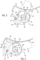
- FIGS. 3 and 4 show the counterknife system in greater detail.
- FIG. 3 shows the counterknife system in the extended position, in which the blades 134 extend to the cutting chamber 122.
- FIG. 4 shows the counterknife system in the retracted position, in which the blades 134 are retracted outside the cutting chamber 122.
- the counterknife system optionally may be operated at one or more intermediate positions between the extended position and the retracted position. In some cases, the blades 134 may remain at least partially within the cutting chamber 122 when the counterknife system is in the fully-retracted position.
- the counterknife blade shaft 128 extends parallel to the cutting knife shaft 124 along a blade shaft direction 136 (which is orthogonal to the page in FIGS. 2-5 ).
- the blade shaft direction 136 is shown at the axis of rotation of the blade shaft 128, but it will be understood that references herein to a part extending along the blade shaft direction 136 do not require that part to be collinear with the blade shaft rotation axis.
- the blade shaft 128 may be rotated or otherwise moved by any suitable mechanism, such as a dedicated drive motor or hydraulic actuator, a power takeoff from another powered system, and so on.
- the counterknife assembly 130 has a blade mount 132 that is removably secured to the blade shaft 128, and one or more blades 134 that extend away from the axis of rotation of the blade shaft 128.
- the blades 134 may be removably mounted to the blade mount, and may be reversible to help prolong operation of the chopper before having to replace or resharpen the blade edges.
- the blades 134 may be integrally formed with or permanently attached to the blade mount 132.
- the blade edges 140 may extend at any desired angle and position relative to the rotation axis.
- the blade edges 140 are offset from the rotation axis, and configured to interact with the edges of the cutting knives 126 at an angle of about 17 degrees when the counterknife assembly is in the fully-extended positions.
- Other alternatives and embodiments will be apparent to persons of ordinary skill in the art in view of the present disclosure.
- the blade mount 132 has one or more blocking surfaces 138 defined by an outer face (i.e., the side facing away from the blade shaft 128 rotation axis) of the blade mount 132.
- the blocking surfaces 138 are semicircular, and located concentric to and at least partially surrounding the rotation axis of the blade shaft 128.
- the blade mount 132 has three blocking surfaces 138: a first blocking surface 138 defined as an outer face of the central body of the blade mount 132, and a pair of second blocking surfaces 138 defined as outer faces of debris shields 142 that extend away from the central body of the blade mount 132 in opposite directions along the blade shaft direction 136.
- the debris shields 142 may be integrally formed with the remainder of the blade mount 132, but in the shown example they are secured as separate parts to the blade mount 132.
- the debris shields 142 and blades 134 may be secured by one or more fasteners 144 to the blade mount 132.
- the blocking surfaces 138 are semicircular, but in other cases they may define a complete circle around the blade shaft 128.
- the semicircular blocking surfaces 138 also may be provided in conjunction with non-circular portions of the outer face of the blade mount 132.
- the blocking surface 138 may terminate at flat portions 146 of the outer face through which a fastener 148 is passed to secure the counterknife assembly 130 to the blade shaft 128.
- a number of counterknife assemblies 130 may be mounted next to each other along the blade shaft 128.
- the blocking surfaces 138 of each adjacent pair of counterknife assemblies 130 may be located in close proximity (e.g., within about 5 millimeters) to each other, such that the blocking surfaces 138 of the counterknife assemblies 130 form a collective blocking surface extending along the blade shaft direction 136.
- the blocking surfaces 138 are located in relatively close proximity to the chopper housing 120, and more specifically to a portion of the chopper housing 120 defined by a chopper pan 150.
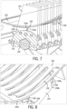
- the chopper pan 150 has slots 152 (see FIG. 8 ) through which the blades 134 pass as the blade shaft 128 is rotated between the retracted position and the extended position.
- the blocking surfaces 138 are at least semicircular, and are concentric with the rotation axis of the blade shaft 128.
- each blocking surface 138 follows a path through a respective predetermined point 154 relative to a respective one of the blade slots 152 throughout the range of motion of the blade shaft 128 between the extended position and the retracted position.
- this predetermined point 154 corresponds to a fixed minimum distance d from the blocking surface 138 to the chopper pan 150.
- the blocking surfaces 138 are positioned to help inhibit residue from passing through the slots 152 throughout the range of motion of the blade shaft 128 and counterknife assemblies 130. It is expected that minimizing the minimum distance d will improve the ability of the blocking surfaces 138 to inhibit residue passage.
- the lowest value for the minimum distance d may be set as the minimum distance to avoid contact between the parts as they deflect during operation, and/or as a distance necessary to avoid contact due to variations in manufacturing tolerances.
- the ability of the blocking surfaces 138 to inhibit residue from passing through the slots 152 can be affected by the radius r of the blocking surfaces 138. For example, increasing the radius r will decrease the distance of the blocking surface 138 from the chopper pan 150 at locations on either side of the point of minimum distance d, thus improving residue blockage further along the slot 152.
- increasing the radius r will decrease the distance of the blocking surface 138 from the chopper pan 150 at locations on either side of the point of minimum distance d, thus improving residue blockage further along the slot 152.
- the blocking surface 138 comprises a smooth semicircular shape, however, it may localized bumps, depressions, ridges or other localized variations in the surface shape to help push residue away as the counterknife assemblies 130 rotate.
- the blocking surface 138 may include ribs that extend parallel to, perpendicular to, or in a helical pattern relative to the rotation axis.
- the blocking surface 138 also may include annular walls that extend radially outward to inhibit residue from moving along the blade shaft direction 136.
- Other alternatives and embodiments will be apparent to persons of ordinary skill in the art in view of the present disclosure.
- each blocking surface scraper 156 has a proximal end 156a secured to the chopper pan 150, and a distal end 156b that is spaced away from the chopper pan 150 and located at the respective predetermined point 154 through which the blocking surface 138 moves as it rotates.
- the distal end 156b may contact the blocking surface 138, but this is not strictly required.
- the distal end 156b is oriented at a non-perpendicular angle relative to the adjacent portion of the blocking surface 138, which may help to drive the residue primarily in one direction to remove it from the blocking surface 138.
- the blocking surface scrapers 156 may be mounted to the chopper pan 150 in any suitable manner.
- the blocking surface scrapers 156 may be secured to the chopper pan 150 by rivets, bolts, weldments, and so on.
- the blocking surface scrapers 156 also may be flexible and mounted to bias them into contact with the blocking surface 138, or to be able to flex out of the way of rocks or other debris that might otherwise damage them.
- the blocking surface scrapers are attached to the chopper pan 150 in the form of cantilevered springs having one or more integral flexible regions.
- the blocking surface scrapers 156 may be made of any suitable material, such as bent steel sheet or the like.
- a respective blocking surface scraper 156 may be provided for each blocking surface 138.
- a number of blocking surface scrapers 156 may be formed from a single sheet, with a continuous strip 156c of the sheet material extending along the blade shaft direction 136 in front of the leading ends 152a of the slots 152, to join the blocking surface scrapers 156 together (see, e.g., FIG. 10 ).
- Other alternatives and embodiments will be apparent to persons of ordinary skill in the art in view of the present disclosure.
- Embodiments also may include blade scrapers 158 that are located along the length of each blade 134 and configured to help remove debris from the blades 134 as they move between the extended and retracted positions.
- blade scrapers may be located just forward of the trailing ends 152b of the slots 152 to contact or be in close proximity to the side surfaces of the blades 134.
- the blade scrapers 158 may have generally the same construction as the blocking surface scrapers 156.
- each blade scraper 158 may have a proximal end 158a secured to the chopper pan 150 and a distal end 158b spaced away from the chopper pan 150 and located adjacent to a respective blade 134 when the blade shaft 128 is in the retracted position.
- the blade scrapers 158 also may comprise any suitable material, and may be joined by a continuous strip of material 158c extending in the blade shaft direction 136 behind the slot trailing ends 152b (see, e.g., FIG. 10 ).
- a continuous strip of material 158c extending in the blade shaft direction 136 behind the slot trailing ends 152b (see, e.g., FIG. 10 ).
- Other alternatives and embodiments will be apparent to persons of ordinary skill in the art in view of the present disclosure.
- the blade shaft 128 is mounted on two or more blade shaft supports 160 by rotating bearings 162, bushings or the like.
- each blade shaft support 160 includes a yoke 190 that wraps around the blade shaft 128, and is secured to the remainder of the blade shaft support 160 by fasteners 192.
- the blade shaft may include circular regions (if it is not otherwise circular) that provide rotating interfaces with the blade shaft support 160 and its yoke 190, such as shown, but there also may be bearings or bushings interposed to provide a rotating support.
- two or more blade shaft supports 160 may be joined by a crossbar 194 to form a unitary assembly.
- the crossbar 194 is bolted to the chopper pan 150 at a flange 196 that extends away from the cutting chamber 122, but other attachments may be used.
- blade supports 160 may be provided, and the blade shaft supports 160 may connect to other structures, such as another part of the chopper assembly or the chassis of the vehicle.
- Other alternatives and embodiments will be apparent to persons of ordinary skill in the art in view of the present disclosure.
- the blade shaft 128 may also include one or more blade shaft guides that help prevent the blade shaft 128 from deflecting.
- each blade shaft guide comprises two main components: a guide pin 164 (best shown in FIGS. 1-3 ) and a guide plate 166.
- Each guide pin 164 extends along the blade shaft direction 136, and is secured to the chopper pan 150 by a pin support 168.
- Each guide plate 166 is secured to the blade shaft 128, and extends in a plane orthogonal to the blade shaft direction 136.
- Each guide plate 166 includes a semicircular slot 170 that is concentric to the rotation axis of the blade shaft 128.
- each pin 164 is captured in the a respective slot 170 with respect to motion along the blade shaft direction 136.
- each guide pin 164 may comprise a threaded rod having nuts or washers located on each side of the guide plate 166 to prevent the guide pin 164 from moving relative to the guide plate 166 along the blade shaft direction 136.
- Each slot 170 is long enough to allow the blade shaft 128 to rotate through its full range of motion between the retracted position to the extended position.
- the slots 170 also may include a void 172, extending from one or both ends of the slot 170 and outside the guide pin's 164 travel path, to provide an escape path for residue that might be pushed along the slot 170 by the guide pin 176.
- the void 172 may, for example, comprise a narrowed extension of the slot 170 that is too small for the guide pin 164 to enter, or simply a portion of the slot 170 into which the guide pin 164 cannot travel due to other constraints on the motion of the parts.
- the guide pins 164 and guide plates 166 interact to allow the blade shaft 128 to rotate, but inhibit the blade shaft from flexing out of parallel with the blade shaft direction 136. It will be understood that the foregoing embodiment may be modified in various ways, such as by mounting the guide pin 164 to the blade shaft 128, and mounting the guide plate 166 to the chopper pan 150. Other alternatives and embodiments will be apparent to persons of ordinary skill in the art in view of the present disclosure.
- the blade shaft 128 also may include one or more lever arms 174 by which the blade shaft 128 can be rotated. In the shown example, there are two lever arms 174, and these are formed integrally with respective guide plates 166. In other cases there may be more or fewer lever arms 174, and they need not be integral with guide plates 166. It is also contemplated that the blade shaft 128 may be rotated by lever arms, drive motors or the like, that are located at each end of the blade shaft 128, rather than by lever arms located along the length of the blade shaft 128. The lever arms 174 also may be replaced by gears, chain sprockets, or other suitable drive linkages. The bladed shaft 128 also may include fixed or adjustable travel stops 178 that control the rotational range of movement of the blade shaft 128 by contacting nearby objects at the end of the desired travel range.
- the blade shaft 128 may be operated by any suitable linkage of force transferring members.
- the lever arms 174 are connected to links 180 that extend to drive levers 182 mounted to the chopper pan 150 or to any other suitable structure, such as the vehicle chassis 102.
- the drive levers 182 are secured to a common rotatable drive shaft 184, so that the drive levers 182 rotate in unison about the drive shaft's rotation axis, which preferably is parallel to the blade shaft direction 136.
- the drive shaft 184 is rotated about its axis by an actuator 186, such as a hydraulic piston and cylinder assembly that is secured to the drive shaft 184 by a dedicated drive lever 188 or by one of the other drive levers 182.
- the actuator 186 is secured at its other end to the vehicle 102 or some other fixed object. Any suitable drive system, such as a conventional pressurized hydraulic system, may be used to operate the actuator 186.
- embodiments may be provided to the market in various states of assembly.
- a counterknife assembly having a blocking surface as described herein, which may be provided with or without blades and fasteners.
- Another embodiment may be provided as an assembly of a blade shaft having counterknife assemblies.
- Another embodiment may be provided as a counterknife system having a blade shaft, counterknife assemblies, a chopper pan, and other parts, which can be installed in an existing harvester.
- Another embodiment may be provided as a towed agricultural harvester machine having a powered residue chopper with a counterknife system as described herein.
- Another embodiment may be provided as an self-propelled agricultural harvester including a threshing and separating system, powered drive wheels, and counterknife system as described herein.
- a threshing and separating system including a threshing and separating system, powered drive wheels, and counterknife system as described herein.
- Other alternatives and embodiments will be apparent to persons of ordinary skill in the art in view of the present disclosure.
Landscapes
- Life Sciences & Earth Sciences (AREA)
- Environmental Sciences (AREA)
- Threshing Machine Elements (AREA)
- Harvester Elements (AREA)
Abstract
Description
- Agricultural machines, such as combine harvesters, typically process crop material, and deposit a portion of the material on the ground behind the machine. As the purpose of the harvester is to collect grain, the material that is deposited is primarily material other than grain ("MoG"), such as chaff and stalks. This is commonly called "residue." It is generally desirable to minimize the size of the residue pieces, and to spread the residue evenly across the path of the machine. For this purpose, the machine may include a chopper to reduce the residue size, and a spreader to distribute the residue.
- The chopper typically comprises a series of knives that rotate on a shaft and are partially enclosed by a shroud. The residue enters the shroud, and the knives strike and cut the residue. A typical chopper also has counterknives that extend radially towards the shaft, and between adjacent pairs of the rotating knives. The counterknives face towards the incoming stream of residue, and provide additional cutting edges. The counterknives can be mounted on their own shaft or on a support that can be moved to extend and retract the counterknives.
- The counterknives enter the chopper housing through slots, and residue can enter these slots. As the residue accumulates, it can inhibit the movement and operation of the counterknives. The inventors have found that further improvements to counterknives can benefit the art.
- This description of the background is provided to assist with an understanding of the following explanations of exemplary embodiments, and is not an admission that any or all of this background information is necessarily prior art.
- In one exemplary aspect, there is provided a residue counterknife assembly comprising: a blade mount configured to secure to a blade shaft having a rotation axis; one or more blades secured to the blade mount and extending away from the rotation axis; and at least one blocking surface comprising an at least semicircular outer face located concentric to and at least partially surrounding the rotation axis.
- In another exemplary aspect, there is provided a residue counterknife system for use on an agricultural harvester. The residue counterknife system comprises: a blade shaft extending along a blade shaft direction; a chopper pan extending parallel to the blade shaft direction and comprising a plurality of blade slots spaced along the blade shaft direction; at least two blade shaft supports spaced apart along the blade shaft direction, wherein the at least two blade shaft supports are configured to rotatably support the blade shaft to rotate about a rotation axis that is parallel to the blade shaft direction, through a range of motion between an extended position and a retracted position; and a plurality of counterknife assemblies attached to the blade shaft along the blade shaft direction. Each counterknife assembly comprises: a blade mount, one or more blades secured to the blade mount and extending away from the rotation axis, wherein each blade is positioned to extend through a respective one of the blade slots at least when the blade shaft is in the extended position, and at least one blocking surface comprising an at least semicircular outer face located concentric to and at least partially surrounding the rotation axis, wherein a portion of the blocking surface passes through a respective predetermined point relative to a respective one of the blade slots throughout the range of motion of the blade shaft between the extended position and the retracted position.
- In another exemplary aspect, there is provided an agricultural harvester machine comprising: a chassis configured for movement on a surface; and a residue chopper comprising: a housing defining a cutting chamber, a cutting knife assembly mounted in the cutting chamber to rotate about a cutting knife rotation axis, a blade shaft located outside the housing and extending along a blade shaft direction that is parallel to the cutting knife rotation axis, a chopper pan extending parallel to the blade shaft direction and defining a portion of the housing defining the cutting chamber, the chopper pan comprising a plurality of blade slots spaced along the blade shaft direction, at least two blade shaft supports spaced apart along the blade shaft direction, wherein the at least two blade shaft supports are configured to rotatably support the blade shaft to the chopper pan to rotate about a rotation axis that is parallel to the blade shaft direction, through a range of motion between an extended position and a retracted position, an actuator configured to move the blade shaft through the range of motion between an extended position and a retracted position, and a plurality of counterknife assemblies attached to the blade shaft along the blade shaft direction. Each counterknife assembly comprises: a blade mount, one or more blades secured to the blade mount and extending away from the rotation axis, wherein each blade is positioned to extend through a respective one of the blade slots at least when the blade shaft is in the extended position, and at least one blocking surface comprising an at least semicircular outer face located concentric to and at least partially surrounding the rotation axis, wherein a portion of the blocking surface passes through a respective predetermined point relative to a respective one of the blade slots throughout the range of motion of the blade shaft between the extended position and the retracted position.
- Embodiments of inventions will now be described, strictly by way of example, with reference to the accompanying drawings, in which:
-
FIG. 1 schematically illustrates a side view of an example of an agricultural combine having residue chopper features such as described herein. -
FIG. 2 is a cross-section view of a crop residue chopper having an exemplary embodiment of a residue counterknife assembly. -
FIG. 3 is a cross-section view of the residue counterknife assembly ofFIG. 2 in an extended position. -
FIG. 4 is a cross-section view of the residue counterknife assembly ofFIG. 2 in a retracted position. -
FIG. 5 is an isometric cross-section view of an exemplary counterknife assembly. -
FIG. 6 is an isometric view of an exemplary blade shaft with counterknife assemblies attached to the blade shaft. -
FIG. 7 is an isometric cross-section view of an exemplary blade shaft with counterknife assemblies attached to the blade shaft, and a chopper pan. -
FIG. 8 is an isometric view of the assembly ofFIG. 7 shown from a different angle. -
FIG. 9 is an isometric view of an exemplary blade shaft. -
FIG. 10 is an isometric view of an exemplary chopper pan assembly. -
FIG. 11 is an isometric view of an exemplary counterknife system including a drive system. -
FIGS. 12 and 13 views of a counterknife assembly mounting system. - In the figures, like reference numerals refer to the same or similar elements.
- Exemplary embodiments of the present invention provide choppers and counterknives that may be used in agricultural equipment (e.g., combines, windrowers, etc.), or in other environments. However, the invention is not limited to any particular application except as may be specifically recited in the claims.
- Referring to
FIG. 1 , an example of anagricultural combine 100 is schematically illustrated. Thecombine 100 includes achassis 102 that is supported for movement on the ground by wheels 104 (e.g., pneumatic tires or tracked wheels). Aheader assembly 106 is attached to thecombine 100 and configured to receive crop material and convey such material to a threshing and separatingsystem 108 located in or on thechassis 102. The threshing and separatingsystem 108 separates grain from the remaining crop material (also known as "straw," "material other than grain," "MoG," "crop residue," or simply "residue") and anauger 110 or the like conveys the grain to agrain hopper 112. The threshing and separating system may comprise an axial flow thresher, twin axial flow thresher, crossflow thresher, and so on. Anunloader boom 114 may be provided to remove the separated grain as thecombine 100 operates. - The residue exits the threshing and separating
system 108 and falls into, or is otherwise conveyed to, acrop residue chopper 116, such as those described herein. Theresidue chopper 116 comminutes the residue, and the residue is then delivered to aspreader 118 that distributes the residue behind thecombine 100. - The features described in relation to
FIG. 1 are generally conventional, except for theresidue chopper 116, and no further explanations of their structures or operations are necessary. - Details of an exemplary
crop residue chopper 116 are shown in more detail inFigures 2-4 . Thecrop residue chopper 116 generally includes ahousing 120 that defines acutting chamber 122, ashaft 124 rotatably mounted in thecutting chamber 122, and a plurality ofcutting knives 126 mounted on theshaft 124 to rotate within thecutting chamber 122. Thecutting knives 126 may be rigidly fixed to theshaft 124 or connected by pivoting links (i.e., flail-type connections). Thehousing 120 is configured with an infeed opening 122' to direct residue into the path of thecutting knives 126, and an outfeed opening 122" to expel the chopped residue. Thehousing 120,cutting chamber 122,shaft 124, andcutting knives 126 may have any suitable or conventional construction, as known in the art, and need not be described in further detail herein. - The
crop residue chopper 116 also includes a counterknife system comprising acounterknife blade shaft 128 to whichcounterknife assemblies 130 are attached by one or more bolts, screws, or other fasteners. Eachcounterknife assembly 130 includes aknife holder 132 having one ormore blades 134 mounted thereon. Any number ofcounterknife assemblies 130 may be attached along the length of theblade shaft 128, and thecounterknife assemblies 130 also may be used in conjunction with other types of counterknives or counterknife assemblies not specifically described herein. -
FIGS. 3 and 4 show the counterknife system in greater detail.FIG. 3 shows the counterknife system in the extended position, in which theblades 134 extend to thecutting chamber 122.FIG. 4 shows the counterknife system in the retracted position, in which theblades 134 are retracted outside thecutting chamber 122. The counterknife system optionally may be operated at one or more intermediate positions between the extended position and the retracted position. In some cases, theblades 134 may remain at least partially within thecutting chamber 122 when the counterknife system is in the fully-retracted position. - The
counterknife blade shaft 128 extends parallel to thecutting knife shaft 124 along a blade shaft direction 136 (which is orthogonal to the page inFIGS. 2-5 ). In the figures, theblade shaft direction 136 is shown at the axis of rotation of theblade shaft 128, but it will be understood that references herein to a part extending along theblade shaft direction 136 do not require that part to be collinear with the blade shaft rotation axis. Theblade shaft 128 may be rotated or otherwise moved by any suitable mechanism, such as a dedicated drive motor or hydraulic actuator, a power takeoff from another powered system, and so on. - Referring now more specifically to
FIGS. 3-5 , anexemplary counterknife assembly 130 is shown and described in greater detail. As noted above, thecounterknife assembly 130 has ablade mount 132 that is removably secured to theblade shaft 128, and one ormore blades 134 that extend away from the axis of rotation of theblade shaft 128. Theblades 134 may be removably mounted to the blade mount, and may be reversible to help prolong operation of the chopper before having to replace or resharpen the blade edges. In other cases, theblades 134 may be integrally formed with or permanently attached to theblade mount 132. The blade edges 140 may extend at any desired angle and position relative to the rotation axis. In the shown example, the blade edges 140 are offset from the rotation axis, and configured to interact with the edges of the cuttingknives 126 at an angle of about 17 degrees when the counterknife assembly is in the fully-extended positions. Other alternatives and embodiments will be apparent to persons of ordinary skill in the art in view of the present disclosure. - The
blade mount 132 has one or more blocking surfaces 138 defined by an outer face (i.e., the side facing away from theblade shaft 128 rotation axis) of theblade mount 132. The blocking surfaces 138 are semicircular, and located concentric to and at least partially surrounding the rotation axis of theblade shaft 128. In the shown example, theblade mount 132 has three blocking surfaces 138: afirst blocking surface 138 defined as an outer face of the central body of theblade mount 132, and a pair of second blocking surfaces 138 defined as outer faces ofdebris shields 142 that extend away from the central body of theblade mount 132 in opposite directions along theblade shaft direction 136. The debris shields 142 may be integrally formed with the remainder of theblade mount 132, but in the shown example they are secured as separate parts to theblade mount 132. For example, the debris shields 142 andblades 134 may be secured by one ormore fasteners 144 to theblade mount 132. - In other embodiments, there may be a
single blade 134 with a blockingsurface 138 on one or both sides of theblade 134. In other cases, there may be more than twoblades 134 attached to theblade mount 132, with or without arespective blocking surface 138 located between each adjacent pair ofblades 134. - In the shown example, the blocking
surfaces 138 are semicircular, but in other cases they may define a complete circle around theblade shaft 128. The semicircular blocking surfaces 138 also may be provided in conjunction with non-circular portions of the outer face of theblade mount 132. For example, the blockingsurface 138 may terminate atflat portions 146 of the outer face through which afastener 148 is passed to secure thecounterknife assembly 130 to theblade shaft 128. - Referring to
FIG. 6 , a number ofcounterknife assemblies 130 may be mounted next to each other along theblade shaft 128. The blocking surfaces 138 of each adjacent pair ofcounterknife assemblies 130 may be located in close proximity (e.g., within about 5 millimeters) to each other, such that the blocking surfaces 138 of thecounterknife assemblies 130 form a collective blocking surface extending along theblade shaft direction 136. - As best shown in
FIGS. 3 and 4 , the blockingsurfaces 138 are located in relatively close proximity to thechopper housing 120, and more specifically to a portion of thechopper housing 120 defined by achopper pan 150. Thechopper pan 150 has slots 152 (seeFIG. 8 ) through which theblades 134 pass as theblade shaft 128 is rotated between the retracted position and the extended position. As noted above, the blockingsurfaces 138 are at least semicircular, and are concentric with the rotation axis of theblade shaft 128. Thus, as theblade shaft 128 andcounterknife assemblies 130 turn about the rotation axis, a portion of each blockingsurface 138 follows a path through a respectivepredetermined point 154 relative to a respective one of theblade slots 152 throughout the range of motion of theblade shaft 128 between the extended position and the retracted position. In the drawings, thispredetermined point 154 corresponds to a fixed minimum distance d from the blockingsurface 138 to thechopper pan 150. - As a result of this construction, the blocking
surfaces 138 are positioned to help inhibit residue from passing through theslots 152 throughout the range of motion of theblade shaft 128 andcounterknife assemblies 130. It is expected that minimizing the minimum distance d will improve the ability of the blocking surfaces 138 to inhibit residue passage. The lowest value for the minimum distance d may be set as the minimum distance to avoid contact between the parts as they deflect during operation, and/or as a distance necessary to avoid contact due to variations in manufacturing tolerances. - It is also contemplated that the ability of the blocking surfaces 138 to inhibit residue from passing through the
slots 152 can be affected by the radius r of the blocking surfaces 138. For example, increasing the radius r will decrease the distance of the blockingsurface 138 from thechopper pan 150 at locations on either side of the point of minimum distance d, thus improving residue blockage further along theslot 152. Other alternatives and embodiments will be apparent to persons of ordinary skill in the art in view of the present disclosure. - In the shown examples, the blocking
surface 138 comprises a smooth semicircular shape, however, it may localized bumps, depressions, ridges or other localized variations in the surface shape to help push residue away as thecounterknife assemblies 130 rotate. For example, the blockingsurface 138 may include ribs that extend parallel to, perpendicular to, or in a helical pattern relative to the rotation axis. The blockingsurface 138 also may include annular walls that extend radially outward to inhibit residue from moving along theblade shaft direction 136. Other alternatives and embodiments will be apparent to persons of ordinary skill in the art in view of the present disclosure. - Referring now also to
FIGS. 7 and 8 , while the blocking surfaces 138 are expected to be helpful on their own, embodiments also may include blockingsurface scrapers 156 that contact or come close to contacting the blocking surfaces 138 as they move, to help remove any residue that might pass through theslots 152. The blockingsurface scrapers 156 may be mounted anywhere where they can clear residue from the blocking surfaces 138. In the shown embodiment, the each blockingsurface scraper 156 has aproximal end 156a secured to thechopper pan 150, and adistal end 156b that is spaced away from thechopper pan 150 and located at the respectivepredetermined point 154 through which the blockingsurface 138 moves as it rotates. Thedistal end 156b may contact the blockingsurface 138, but this is not strictly required. In the shown example, thedistal end 156b is oriented at a non-perpendicular angle relative to the adjacent portion of the blockingsurface 138, which may help to drive the residue primarily in one direction to remove it from the blockingsurface 138. - The blocking
surface scrapers 156 may be mounted to thechopper pan 150 in any suitable manner. For example, the blockingsurface scrapers 156 may be secured to thechopper pan 150 by rivets, bolts, weldments, and so on. The blockingsurface scrapers 156 also may be flexible and mounted to bias them into contact with the blockingsurface 138, or to be able to flex out of the way of rocks or other debris that might otherwise damage them. In the shown example, the blocking surface scrapers are attached to thechopper pan 150 in the form of cantilevered springs having one or more integral flexible regions. The blockingsurface scrapers 156 may be made of any suitable material, such as bent steel sheet or the like. - Although not strictly required, a respective
blocking surface scraper 156 may be provided for each blockingsurface 138. For convenience, a number of blockingsurface scrapers 156 may be formed from a single sheet, with acontinuous strip 156c of the sheet material extending along theblade shaft direction 136 in front of the leading ends 152a of theslots 152, to join the blockingsurface scrapers 156 together (see, e.g.,FIG. 10 ). Other alternatives and embodiments will be apparent to persons of ordinary skill in the art in view of the present disclosure. - Embodiments also may include
blade scrapers 158 that are located along the length of eachblade 134 and configured to help remove debris from theblades 134 as they move between the extended and retracted positions. For example, blade scrapers may be located just forward of the trailing ends 152b of theslots 152 to contact or be in close proximity to the side surfaces of theblades 134. Theblade scrapers 158 may have generally the same construction as the blockingsurface scrapers 156. For example, eachblade scraper 158 may have aproximal end 158a secured to thechopper pan 150 and adistal end 158b spaced away from thechopper pan 150 and located adjacent to arespective blade 134 when theblade shaft 128 is in the retracted position. Theblade scrapers 158 also may comprise any suitable material, and may be joined by a continuous strip of material 158c extending in theblade shaft direction 136 behind the slot trailing ends 152b (see, e.g.,FIG. 10 ). Other alternatives and embodiments will be apparent to persons of ordinary skill in the art in view of the present disclosure. - Referring now to
FIGS. 1-3 and9-13 , examples of mounting arrangements for theblade shaft 128 are shown and described in detail. Theblade shaft 128 is mounted on two or more blade shaft supports 160 by rotatingbearings 162, bushings or the like. In the case ofFIG. 10 , there are two blade shaft supports 160 secured to thechopper pan 150, such as by being welded to thechopper pan 150, with one blade shaft support located at each end of theblade shaft 128. In the embodiment ofFIGS. 12 and 13 , there are two additional blade shaft supports 160 located at intermediate positions along the blade shaft 128 (in addition to or instead of the ones located at each end, as shown inFIG. 10 ). In this case, eachblade shaft support 160 includes ayoke 190 that wraps around theblade shaft 128, and is secured to the remainder of theblade shaft support 160 byfasteners 192. The blade shaft may include circular regions (if it is not otherwise circular) that provide rotating interfaces with theblade shaft support 160 and itsyoke 190, such as shown, but there also may be bearings or bushings interposed to provide a rotating support. As best shown inFIG. 12 , two or more blade shaft supports 160 may be joined by acrossbar 194 to form a unitary assembly. In this case, thecrossbar 194 is bolted to thechopper pan 150 at aflange 196 that extends away from the cuttingchamber 122, but other attachments may be used. In other cases, other numbers of blade supports 160 may be provided, and the blade shaft supports 160 may connect to other structures, such as another part of the chopper assembly or the chassis of the vehicle. Other alternatives and embodiments will be apparent to persons of ordinary skill in the art in view of the present disclosure. - The
blade shaft 128 may also include one or more blade shaft guides that help prevent theblade shaft 128 from deflecting. In this example, each blade shaft guide comprises two main components: a guide pin 164 (best shown inFIGS. 1-3 ) and aguide plate 166. Eachguide pin 164 extends along theblade shaft direction 136, and is secured to thechopper pan 150 by apin support 168. Eachguide plate 166 is secured to theblade shaft 128, and extends in a plane orthogonal to theblade shaft direction 136. Eachguide plate 166 includes asemicircular slot 170 that is concentric to the rotation axis of theblade shaft 128. - Each
pin 164 is captured in the arespective slot 170 with respect to motion along theblade shaft direction 136. For example, eachguide pin 164 may comprise a threaded rod having nuts or washers located on each side of theguide plate 166 to prevent theguide pin 164 from moving relative to theguide plate 166 along theblade shaft direction 136. Eachslot 170 is long enough to allow theblade shaft 128 to rotate through its full range of motion between the retracted position to the extended position. Theslots 170 also may include avoid 172, extending from one or both ends of theslot 170 and outside the guide pin's 164 travel path, to provide an escape path for residue that might be pushed along theslot 170 by the guide pin 176. The void 172 may, for example, comprise a narrowed extension of theslot 170 that is too small for theguide pin 164 to enter, or simply a portion of theslot 170 into which theguide pin 164 cannot travel due to other constraints on the motion of the parts. - In use, the guide pins 164 and guide
plates 166 interact to allow theblade shaft 128 to rotate, but inhibit the blade shaft from flexing out of parallel with theblade shaft direction 136. It will be understood that the foregoing embodiment may be modified in various ways, such as by mounting theguide pin 164 to theblade shaft 128, and mounting theguide plate 166 to thechopper pan 150. Other alternatives and embodiments will be apparent to persons of ordinary skill in the art in view of the present disclosure. - The
blade shaft 128 also may include one ormore lever arms 174 by which theblade shaft 128 can be rotated. In the shown example, there are twolever arms 174, and these are formed integrally withrespective guide plates 166. In other cases there may be more orfewer lever arms 174, and they need not be integral withguide plates 166. It is also contemplated that theblade shaft 128 may be rotated by lever arms, drive motors or the like, that are located at each end of theblade shaft 128, rather than by lever arms located along the length of theblade shaft 128. Thelever arms 174 also may be replaced by gears, chain sprockets, or other suitable drive linkages. Thebladed shaft 128 also may include fixed or adjustable travel stops 178 that control the rotational range of movement of theblade shaft 128 by contacting nearby objects at the end of the desired travel range. - The
blade shaft 128 may be operated by any suitable linkage of force transferring members. In this example, thelever arms 174 are connected tolinks 180 that extend to drivelevers 182 mounted to thechopper pan 150 or to any other suitable structure, such as thevehicle chassis 102. The drive levers 182 are secured to a commonrotatable drive shaft 184, so that the drive levers 182 rotate in unison about the drive shaft's rotation axis, which preferably is parallel to theblade shaft direction 136. Thedrive shaft 184 is rotated about its axis by anactuator 186, such as a hydraulic piston and cylinder assembly that is secured to thedrive shaft 184 by adedicated drive lever 188 or by one of the other drive levers 182. Theactuator 186 is secured at its other end to thevehicle 102 or some other fixed object. Any suitable drive system, such as a conventional pressurized hydraulic system, may be used to operate theactuator 186. - It will appreciated that embodiments may be provided to the market in various states of assembly. For example, one embodiment may be provided as a counterknife assembly having a blocking surface as described herein, which may be provided with or without blades and fasteners. Another embodiment may be provided as an assembly of a blade shaft having counterknife assemblies. Another embodiment may be provided as a counterknife system having a blade shaft, counterknife assemblies, a chopper pan, and other parts, which can be installed in an existing harvester. Another embodiment may be provided as a towed agricultural harvester machine having a powered residue chopper with a counterknife system as described herein. Another embodiment may be provided as an self-propelled agricultural harvester including a threshing and separating system, powered drive wheels, and counterknife system as described herein. Other alternatives and embodiments will be apparent to persons of ordinary skill in the art in view of the present disclosure.
- The present disclosure describes a number of inventive features and/or combinations of features that may be used alone or in combination with each other or in combination with other technologies. The embodiments described herein are all exemplary, and are not intended to limit the scope of the claims. It will be appreciated that various aspects of the embodiments described herein may be provided as component parts or as subassemblies. It will also be appreciated that the inventions described herein can be modified and adapted in various ways, and all such modifications and adaptations are intended to be included in the scope of this disclosure and the appended claims.
Claims (15)
- A residue counterknife assembly (130) comprising:a blade mount (132) configured to secure to a blade shaft (128) having a rotation axis;one or more blades (134) secured to the blade mount (132) and extending away from the rotation axis; andat least one blocking surface (138) comprising an at least semicircular outer face located concentric to and at least partially surrounding the rotation axis.
- The residue counterknife assembly (130) according to any of the previous claims, wherein the one or more blades (134) are removably mounted to the blade mount (132).
- The residue counterknife assembly (130) according to any of the previous claims, wherein the at least one blocking surface (138) comprises an outer face of the blade mount (132).
- The residue counterknife assembly (130) according to any of the previous claims, wherein the outer face of the blade mount (132) is positioned, with respect to the rotation axis, between a first blade (134) secured to the blade mount (132) and a second blade (134) secured to the blade mount (132).
- The residue counterknife assembly (130) according to any of the previous claims, wherein the at least one blocking surface (138) comprises an outer face of a debris shield (142) removably connected to the blade mount (132) and one or more blades (134).
- The residue counterknife assembly (130) according to any of the previous claims, wherein the at least one blocking surface (138) comprises a respective outer face of a first debris shield (142) and a respective outer face of a second debris shield (142), wherein the one or more blades (134) are positioned, with respect to the rotation axis, between the respective outer face of the first debris shield (142) and the respective outer face of the second debris shield (142).
- The residue counterknife assembly (130) according to any of the previous claims, wherein the at least one blocking surface (138) comprises:a respective outer face of a first debris shield (142);a respective outer face of a second debris shield (142); anda respective outer face of the blade mount (132);wherein the one or more blades (134) comprises:a first blade (134) positioned, with respect to the rotation axis, between the respective outer face of the first debris shield (142) and the respective outer face of the blade mount (132), anda second blade (134) positioned, with respect to the rotation axis, between the respective outer face of the second debris shield (142) and the respective outer face of the blade mount (132).
- A residue counterknife system for use on an agricultural harvester (100), the residue counterknife system comprising:a blade shaft (128) extending along a blade shaft direction (136);a chopper pan (150) extending parallel to the blade shaft direction (136) and comprising a plurality of blade slots (152) spaced along the blade shaft direction (136);at least two blade shaft supports (160) spaced apart along the blade shaft direction (136), wherein the at least two blade shaft supports (160) are configured to rotatably support the blade shaft (128) to rotate about a rotation axis that is parallel to the blade shaft direction (136), through a range of motion between an extended position and a retracted position; anda plurality of counterknife assemblies (130) according to any of the preceding claims.
- The residue counterknife system of claim 8, wherein the respective blocking surfaces (138) of the plurality of counterknife assemblies (130) form a collective blocking surface (138) extending along the blade shaft direction (136).
- The residue counterknife system of claim 8 and/or 9, further comprising a plurality of blocking surface scrapers (156), each blocking surface scraper (156) having a respective proximal end (156a) secured to the chopper pan (150) and a respective distal end (156b) spaced away from the chopper pan (150) and located at the respective predetermined point of at least one blocking surface (138).
- The residue counterknife system of claim 10, wherein the respective distal end (156b) of each blocking surface scraper (156) is positioned to contact the at least semicircular outer face of the at least one respective blocking surface (138) throughout the range of motion of the blade shaft (128) between the extended position and the retracted position.
- The residue counterknife system according to any of the claims 8 to 11, further comprising a plurality of blade scrapers (158), each blade scraper (158) having a respective proximal end (158a) secured to the chopper pan (150) and a respective distal end (158b) spaced away from the chopper pan (150) and located adjacent to a respective blade (134) when the blade shaft (128) is in the retracted position.
- The residue counterknife system according to any of the claims 8 to 12, further comprising one or more blade shaft guides, each blade shaft guide comprising:a guide pin (164) secured to one of the blade shaft (128) and the chopper pan (150) and extending along the blade shaft direction (136);a guide plate (166) secured to the other of the blade shaft (128) and the chopper pan (150) and extending in a plane orthogonal to the blade shaft direction (136) and defining a semicircular slot (170) that is concentric to the rotation axis;wherein the guide pin (164) is captured in the slot (170) with respect to the blade shaft direction (136), and movable along the slot (170) throughout the range of motion of the blade shaft (128) between the extended position and the retracted position.
- The residue counterknife system of claim 13, wherein the guide plate (166) defines at least one void (172) extending from an end of the slot (170) and outside a travel path of the guide pin (164) to provide an escape path for material pushed along the slot (170) by the guide pin (164).
- An agricultural harvester machine (100) comprising:a chassis (102) configured for movement on a surface; anda residue chopper (116) comprising:a housing (120) defining a cutting chamber (122),a cutting knife assembly (124, 126) mounted in the cutting chamber (122) to rotate about a cutting knife rotation axis,a blade shaft (128) located outside the housing (120) and extending along a blade shaft direction (136) that is parallel to the cutting knife rotation axis;a chopper pan (150) extending parallel to the blade shaft direction (136) and defining a portion of the housing (120) defining the cutting chamber (122), the chopper pan (150) comprising a plurality of blade slots (152) spaced along the blade shaft direction (136);at least two blade shaft supports (160) spaced apart along the blade shaft direction (136), wherein the at least two blade shaft supports (160) are configured to rotatably support the blade shaft (128) to the chopper pan (150) to rotate about a rotation axis that is parallel to the blade shaft direction (136), through a range of motion between an extended position and a retracted position,an actuator (186) configured to move the blade shaft (128) through the range of motion between an extended position and a retracted position, anda plurality of counterknife assemblies (130) according to any of the claims 1 to 7.
Applications Claiming Priority (1)
| Application Number | Priority Date | Filing Date | Title |
|---|---|---|---|
| US202363459066P | 2023-04-13 | 2023-04-13 |
Publications (2)
| Publication Number | Publication Date |
|---|---|
| EP4445717A1 true EP4445717A1 (en) | 2024-10-16 |
| EP4445717B1 EP4445717B1 (en) | 2025-12-17 |
Family
ID=90572063
Family Applications (1)
| Application Number | Title | Priority Date | Filing Date |
|---|---|---|---|
| EP24167760.8A Active EP4445717B1 (en) | 2023-04-13 | 2024-03-28 | Straw chopper for combine harvester |
Country Status (2)
| Country | Link |
|---|---|
| US (1) | US20240341238A1 (en) |
| EP (1) | EP4445717B1 (en) |
Cited By (1)
| Publication number | Priority date | Publication date | Assignee | Title |
|---|---|---|---|---|
| EP4620292A1 (en) * | 2024-03-22 | 2025-09-24 | CNH Industrial America LLC | Knife holder for counterknife bank assembly for combine harvester |
Families Citing this family (1)
| Publication number | Priority date | Publication date | Assignee | Title |
|---|---|---|---|---|
| EP4445718B1 (en) * | 2023-04-13 | 2026-02-25 | CNH Industrial America LLC | Fixed blade concentric knife holder for agricultural harvesters |
Citations (4)
| Publication number | Priority date | Publication date | Assignee | Title |
|---|---|---|---|---|
| US20080305842A1 (en) * | 2007-06-05 | 2008-12-11 | Benes Jason M | Reversable counter knife bank |
| EP2055175A1 (en) * | 2007-10-29 | 2009-05-06 | CNH Belgium N.V. | Chopper assembly |
| US20140179383A1 (en) * | 2012-12-26 | 2014-06-26 | Cnh America Llc | Chopper assembly for harvesting equipment |
| EP2798943A1 (en) * | 2013-05-01 | 2014-11-05 | CNH Industrial Belgium nv | Counter knife bank debris deflector |
Family Cites Families (2)
| Publication number | Priority date | Publication date | Assignee | Title |
|---|---|---|---|---|
| US10111384B2 (en) * | 2015-10-09 | 2018-10-30 | Cnh Industrial America Llc | Agricultural chopper with linked counter knives and shear bar |
| US11684016B2 (en) * | 2020-10-29 | 2023-06-27 | Deere & Company | Chopper with movable outlet floor ramp |
-
2024
- 2024-03-28 EP EP24167760.8A patent/EP4445717B1/en active Active
- 2024-04-11 US US18/632,999 patent/US20240341238A1/en active Pending
Patent Citations (4)
| Publication number | Priority date | Publication date | Assignee | Title |
|---|---|---|---|---|
| US20080305842A1 (en) * | 2007-06-05 | 2008-12-11 | Benes Jason M | Reversable counter knife bank |
| EP2055175A1 (en) * | 2007-10-29 | 2009-05-06 | CNH Belgium N.V. | Chopper assembly |
| US20140179383A1 (en) * | 2012-12-26 | 2014-06-26 | Cnh America Llc | Chopper assembly for harvesting equipment |
| EP2798943A1 (en) * | 2013-05-01 | 2014-11-05 | CNH Industrial Belgium nv | Counter knife bank debris deflector |
Cited By (1)
| Publication number | Priority date | Publication date | Assignee | Title |
|---|---|---|---|---|
| EP4620292A1 (en) * | 2024-03-22 | 2025-09-24 | CNH Industrial America LLC | Knife holder for counterknife bank assembly for combine harvester |
Also Published As
| Publication number | Publication date |
|---|---|
| EP4445717B1 (en) | 2025-12-17 |
| US20240341238A1 (en) | 2024-10-17 |
Similar Documents
| Publication | Publication Date | Title |
|---|---|---|
| EP4445717B1 (en) | Straw chopper for combine harvester | |
| EP3153010B1 (en) | Agricultural chopper with linked counter knives and shear bar | |
| US7988080B2 (en) | Rotary chopper element of an integral chopper assembly of a combine harvester | |
| EP2000019B1 (en) | A stationary knife assembly for a chopper assembly | |
| US9137949B2 (en) | Chopper assembly for harvesting equipment | |
| US3670739A (en) | Axial flow combine with a rotary discharge and a straw chopper | |
| US12471535B2 (en) | Residue chopper with counterblades and fins | |
| US6244955B1 (en) | Rotary tine conveyor for a harvesting machine | |
| EP4088558B1 (en) | Chopper arrangement for an agricultural harvester | |
| US20090111549A1 (en) | Combine harvester residue chopper active counter knife assembly | |
| CN109197173B (en) | Shredder assembly with automatic blade return mechanism for a harvester | |
| US10201128B2 (en) | Straw chopper for a combine harvester having counter-blades and a straw dam | |
| EP3108736B1 (en) | Agricultural harvester cutter bar | |
| EP3777515B1 (en) | Crop flow guide vanes | |
| US20250212727A1 (en) | Support system for an element of an agricultural header | |
| EP3087821B1 (en) | Agricultural header with multiple finger infeed assembly | |
| EP4494448A1 (en) | Straw chopper counter knife bar with blade between concave and knife bar pivot | |
| US20240341228A1 (en) | Fixed blade concentric knife holder for agricultural harvesters | |
| BR102024007023A2 (en) | STRAW CHOPPER FOR HARVESTER | |
| US20250194469A1 (en) | Method for reduction of chopper recut | |
| US6662539B1 (en) | Crop harvesting machine with side discharge directed rearward | |
| EP3695704B1 (en) | An impeller conditioner including a tine device with limited lateral movement | |
| BR102024006851A2 (en) | STRAW CHOPPER COUNTER KNIFE BAR WITH BLADE BETWEEN THE CONCAVE AND THE KNIFE BAR PIVOT |
Legal Events
| Date | Code | Title | Description |
|---|---|---|---|
| PUAI | Public reference made under article 153(3) epc to a published international application that has entered the european phase |
Free format text: ORIGINAL CODE: 0009012 |
|
| STAA | Information on the status of an ep patent application or granted ep patent |
Free format text: STATUS: THE APPLICATION HAS BEEN PUBLISHED |
|
| AK | Designated contracting states |
Kind code of ref document: A1 Designated state(s): AL AT BE BG CH CY CZ DE DK EE ES FI FR GB GR HR HU IE IS IT LI LT LU LV MC ME MK MT NL NO PL PT RO RS SE SI SK SM TR |
|
| STAA | Information on the status of an ep patent application or granted ep patent |
Free format text: STATUS: REQUEST FOR EXAMINATION WAS MADE |
|
| 17P | Request for examination filed |
Effective date: 20250416 |
|
| GRAP | Despatch of communication of intention to grant a patent |
Free format text: ORIGINAL CODE: EPIDOSNIGR1 |
|
| STAA | Information on the status of an ep patent application or granted ep patent |
Free format text: STATUS: GRANT OF PATENT IS INTENDED |
|
| RIC1 | Information provided on ipc code assigned before grant |
Ipc: A01F 12/40 20060101AFI20250630BHEP Ipc: A01F 29/09 20100101ALI20250630BHEP |
|
| INTG | Intention to grant announced |
Effective date: 20250718 |
|
| GRAS | Grant fee paid |
Free format text: ORIGINAL CODE: EPIDOSNIGR3 |
|
| GRAA | (expected) grant |
Free format text: ORIGINAL CODE: 0009210 |
|
| STAA | Information on the status of an ep patent application or granted ep patent |
Free format text: STATUS: THE PATENT HAS BEEN GRANTED |
|
| AK | Designated contracting states |
Kind code of ref document: B1 Designated state(s): AL AT BE BG CH CY CZ DE DK EE ES FI FR GB GR HR HU IE IS IT LI LT LU LV MC ME MK MT NL NO PL PT RO RS SE SI SK SM TR |
|
| REG | Reference to a national code |
Ref country code: CH Ref legal event code: F10 Free format text: ST27 STATUS EVENT CODE: U-0-0-F10-F00 (AS PROVIDED BY THE NATIONAL OFFICE) Effective date: 20251217 Ref country code: GB Ref legal event code: FG4D |
|
| REG | Reference to a national code |
Ref country code: DE Ref legal event code: R096 Ref document number: 602024001687 Country of ref document: DE |
|
| REG | Reference to a national code |
Ref country code: LT Ref legal event code: MG9D |
|
| PG25 | Lapsed in a contracting state [announced via postgrant information from national office to epo] |
Ref country code: NO Free format text: LAPSE BECAUSE OF FAILURE TO SUBMIT A TRANSLATION OF THE DESCRIPTION OR TO PAY THE FEE WITHIN THE PRESCRIBED TIME-LIMIT Effective date: 20260317 |
|
| PGFP | Annual fee paid to national office [announced via postgrant information from national office to epo] |
Ref country code: DE Payment date: 20260320 Year of fee payment: 3 |
|
| PG25 | Lapsed in a contracting state [announced via postgrant information from national office to epo] |
Ref country code: FI Free format text: LAPSE BECAUSE OF FAILURE TO SUBMIT A TRANSLATION OF THE DESCRIPTION OR TO PAY THE FEE WITHIN THE PRESCRIBED TIME-LIMIT Effective date: 20251217 Ref country code: HR Free format text: LAPSE BECAUSE OF FAILURE TO SUBMIT A TRANSLATION OF THE DESCRIPTION OR TO PAY THE FEE WITHIN THE PRESCRIBED TIME-LIMIT Effective date: 20251217 |
|
| PGFP | Annual fee paid to national office [announced via postgrant information from national office to epo] |
Ref country code: AT Payment date: 20260301 Year of fee payment: 3 |
|
| PG25 | Lapsed in a contracting state [announced via postgrant information from national office to epo] |
Ref country code: RS Free format text: LAPSE BECAUSE OF FAILURE TO SUBMIT A TRANSLATION OF THE DESCRIPTION OR TO PAY THE FEE WITHIN THE PRESCRIBED TIME-LIMIT Effective date: 20260317 |
|
| PGFP | Annual fee paid to national office [announced via postgrant information from national office to epo] |
Ref country code: FR Payment date: 20260323 Year of fee payment: 3 |
|
| REG | Reference to a national code |
Ref country code: NL Ref legal event code: MP Effective date: 20251217 |
|
| PG25 | Lapsed in a contracting state [announced via postgrant information from national office to epo] |
Ref country code: LV Free format text: LAPSE BECAUSE OF FAILURE TO SUBMIT A TRANSLATION OF THE DESCRIPTION OR TO PAY THE FEE WITHIN THE PRESCRIBED TIME-LIMIT Effective date: 20251217 |
|
| PG25 | Lapsed in a contracting state [announced via postgrant information from national office to epo] |
Ref country code: BG Free format text: LAPSE BECAUSE OF FAILURE TO SUBMIT A TRANSLATION OF THE DESCRIPTION OR TO PAY THE FEE WITHIN THE PRESCRIBED TIME-LIMIT Effective date: 20251217 |
|
| REG | Reference to a national code |
Ref country code: AT Ref legal event code: MK05 Ref document number: 1867592 Country of ref document: AT Kind code of ref document: T Effective date: 20251217 |
|
| PG25 | Lapsed in a contracting state [announced via postgrant information from national office to epo] |
Ref country code: NL Free format text: LAPSE BECAUSE OF FAILURE TO SUBMIT A TRANSLATION OF THE DESCRIPTION OR TO PAY THE FEE WITHIN THE PRESCRIBED TIME-LIMIT Effective date: 20251217 |
|
| PG25 | Lapsed in a contracting state [announced via postgrant information from national office to epo] |
Ref country code: LT Free format text: LAPSE BECAUSE OF FAILURE TO SUBMIT A TRANSLATION OF THE DESCRIPTION OR TO PAY THE FEE WITHIN THE PRESCRIBED TIME-LIMIT Effective date: 20251217 |
|
| PG25 | Lapsed in a contracting state [announced via postgrant information from national office to epo] |
Ref country code: SM Free format text: LAPSE BECAUSE OF FAILURE TO SUBMIT A TRANSLATION OF THE DESCRIPTION OR TO PAY THE FEE WITHIN THE PRESCRIBED TIME-LIMIT Effective date: 20251217 |
|
| PG25 | Lapsed in a contracting state [announced via postgrant information from national office to epo] |
Ref country code: ES Free format text: LAPSE BECAUSE OF FAILURE TO SUBMIT A TRANSLATION OF THE DESCRIPTION OR TO PAY THE FEE WITHIN THE PRESCRIBED TIME-LIMIT Effective date: 20251217 |
|
| PG25 | Lapsed in a contracting state [announced via postgrant information from national office to epo] |
Ref country code: PL Free format text: LAPSE BECAUSE OF FAILURE TO SUBMIT A TRANSLATION OF THE DESCRIPTION OR TO PAY THE FEE WITHIN THE PRESCRIBED TIME-LIMIT Effective date: 20251217 |
|
| PGFP | Annual fee paid to national office [announced via postgrant information from national office to epo] |
Ref country code: IT Payment date: 20260331 Year of fee payment: 3 |
|
| PG25 | Lapsed in a contracting state [announced via postgrant information from national office to epo] |
Ref country code: AT Free format text: LAPSE BECAUSE OF FAILURE TO SUBMIT A TRANSLATION OF THE DESCRIPTION OR TO PAY THE FEE WITHIN THE PRESCRIBED TIME-LIMIT Effective date: 20251217 |
|
| PG25 | Lapsed in a contracting state [announced via postgrant information from national office to epo] |
Ref country code: EE Free format text: LAPSE BECAUSE OF FAILURE TO SUBMIT A TRANSLATION OF THE DESCRIPTION OR TO PAY THE FEE WITHIN THE PRESCRIBED TIME-LIMIT Effective date: 20251217 |
|
| PG25 | Lapsed in a contracting state [announced via postgrant information from national office to epo] |
Ref country code: IS Free format text: LAPSE BECAUSE OF FAILURE TO SUBMIT A TRANSLATION OF THE DESCRIPTION OR TO PAY THE FEE WITHIN THE PRESCRIBED TIME-LIMIT Effective date: 20260417 Ref country code: PT Free format text: LAPSE BECAUSE OF FAILURE TO SUBMIT A TRANSLATION OF THE DESCRIPTION OR TO PAY THE FEE WITHIN THE PRESCRIBED TIME-LIMIT Effective date: 20260417 |
|
| PG25 | Lapsed in a contracting state [announced via postgrant information from national office to epo] |
Ref country code: CZ Free format text: LAPSE BECAUSE OF FAILURE TO SUBMIT A TRANSLATION OF THE DESCRIPTION OR TO PAY THE FEE WITHIN THE PRESCRIBED TIME-LIMIT Effective date: 20251217 |
|
| PG25 | Lapsed in a contracting state [announced via postgrant information from national office to epo] |
Ref country code: SK Free format text: LAPSE BECAUSE OF FAILURE TO SUBMIT A TRANSLATION OF THE DESCRIPTION OR TO PAY THE FEE WITHIN THE PRESCRIBED TIME-LIMIT Effective date: 20251217 |
|
| PG25 | Lapsed in a contracting state [announced via postgrant information from national office to epo] |
Ref country code: SE Free format text: LAPSE BECAUSE OF FAILURE TO SUBMIT A TRANSLATION OF THE DESCRIPTION OR TO PAY THE FEE WITHIN THE PRESCRIBED TIME-LIMIT Effective date: 20251217 |