EP4443447A1 - Liquid cooled cable - Google Patents
Liquid cooled cable Download PDFInfo
- Publication number
- EP4443447A1 EP4443447A1 EP22900256.3A EP22900256A EP4443447A1 EP 4443447 A1 EP4443447 A1 EP 4443447A1 EP 22900256 A EP22900256 A EP 22900256A EP 4443447 A1 EP4443447 A1 EP 4443447A1
- Authority
- EP
- European Patent Office
- Prior art keywords
- liquid cooling
- cooling channel
- liquid
- cable
- cooled
- Prior art date
- Legal status (The legal status is an assumption and is not a legal conclusion. Google has not performed a legal analysis and makes no representation as to the accuracy of the status listed.)
- Pending
Links
Images




Classifications
-
- H—ELECTRICITY
- H01—ELECTRIC ELEMENTS
- H01B—CABLES; CONDUCTORS; INSULATORS; SELECTION OF MATERIALS FOR THEIR CONDUCTIVE, INSULATING OR DIELECTRIC PROPERTIES
- H01B7/00—Insulated conductors or cables characterised by their form
- H01B7/17—Protection against damage caused by external factors, e.g. sheaths or armouring
- H01B7/29—Protection against damage caused by extremes of temperature or by flame
-
- H—ELECTRICITY
- H01—ELECTRIC ELEMENTS
- H01B—CABLES; CONDUCTORS; INSULATORS; SELECTION OF MATERIALS FOR THEIR CONDUCTIVE, INSULATING OR DIELECTRIC PROPERTIES
- H01B7/00—Insulated conductors or cables characterised by their form
- H01B7/42—Insulated conductors or cables characterised by their form with arrangements for heat dissipation or conduction
- H01B7/421—Insulated conductors or cables characterised by their form with arrangements for heat dissipation or conduction for heat dissipation
- H01B7/423—Insulated conductors or cables characterised by their form with arrangements for heat dissipation or conduction for heat dissipation using a cooling fluid
-
- H—ELECTRICITY
- H01—ELECTRIC ELEMENTS
- H01B—CABLES; CONDUCTORS; INSULATORS; SELECTION OF MATERIALS FOR THEIR CONDUCTIVE, INSULATING OR DIELECTRIC PROPERTIES
- H01B7/00—Insulated conductors or cables characterised by their form
- H01B7/02—Disposition of insulation
Definitions
- the present disclosure relates to the field of cable technologies, and in particular to a liquid-cooled cable.
- a cable typically includes a conductor, an insulator, and a sheath.
- the conductor When transmitting current, the conductor generates heat due to its inherent resistance. New energy vehicles currently charge slowly, and increasing the charging speed through high-power charging is a future development trend. The greater the power, the more heat generated by the cable itself. Increasing the cable diameter results in increased cable weight, and long-term usage accelerates the aging of the cable, shortening the service life of the cables.
- An objective of the present disclosure is to provide a liquid-cooled cable, so as to resolve the problems in the prior art.
- the present disclosure increases the liquid cooling channels inside and outside the cable cores, maximizing the cooling effect of the cable, thus enhancing the flow carrying capacity of the cable, reducing the cable weight, and prolonging the service life of the cable.
- a liquid-cooled cable including a liquid cooling channel and at least one set of cable cores with a cross section in a shape of fan.
- the liquid cooling channel includes an internal liquid cooling channel, an external liquid cooling channel, and at least one set of connecting channels.
- the external liquid cooling channel communicates with the internal liquid cooling channel via the connecting channels, and a cooling medium flows in the liquid cooling channel.
- the cable cores are disposed at an outer periphery of the internal liquid cooling channel and an inner periphery of the external liquid cooling channel, and the connecting channels are disposed at a radial direction of the liquid-cooled cable and separate the cable cores.
- liquid-cooled cable in the present disclosure has the following beneficial effects:
- the present disclosure provides a liquid-cooled cable 100, including a liquid cooling channel and at least one set of cable cores 1 with a cross section in a shape of fan.
- the liquid cooling channel includes an internal liquid cooling channel 2, an external liquid cooling channel 3, and at least one set of connecting channels 4.
- the external liquid cooling channel 3 communicates with the internal liquid cooling channel 2 via the connecting channels 4, and a cooling medium flows in the liquid cooling channel.
- the cable cores 1 are disposed at an outer periphery of the internal liquid cooling channel 2 and an inner periphery of the external liquid cooling channel 3, and the connecting channels 4 are disposed at a radial direction of the liquid-cooled cable and separate the cable cores 1.
- the internal liquid cooling channel 2 and the external liquid cooling channel 3 are made of a highly conductive material.
- the liquid cooling channels are increased inside and outside the cable cores, maximizing the cooling effect of the cable, so as to enhancing the flow carrying capacity of the cable and prolonging the service life.
- the cross section around the fan-shaped cable core 1 in the vertical direction may be liquid cooling, maximizing the cooling effect of the cable, so as to enhancing the flow carrying capacity of the cable and prolonging the service life.
- the cable core is configured into the shape of a fan, with each fan-shaped cable core surrounding the outer wall of a circular internal liquid cooling channel.
- the fan-shaped cable cores surround an outer wall of the circular internal liquid cooling channel obtains a smaller cable diameter and facilitates production of miniaturized cables, cable weight reduction, storage and management, and cable movement.
- a radius of the circular internal liquid cooling channel is r
- four fan-shaped cable cores whose radii are all 2r and angle radians are all 90° surround an outer wall of the internal liquid cooling channel to form a circular ring area of S 1.
- S [(2r) 2 -r 2 ] ⁇
- the cable radius is the distance from the central axis of the circular internal liquid cooling pipe to the farthest point on the circular wire core from the central axis of the liquid cooling pipe 2r.
- the material of the liquid cooling channel includes one or more of polyvinyl chloride, polyethylene, polyamide, polytetrafluoroethylene, tetrafluoroethylene/hexafluoropropylene copolymer, ethylene/tetrafluoroethylene copolymer, polypropylene, polyvinylidene fluoride, polyurethane, polyterephthalic acid, polyurethane elastomer, styrene block copolymer, perfluoroalkoxyalkane, chlorinated polyethylene, polyphenylene sulphide, polystyrene, silicone rubber, crosslinked polyolefin, ethylene propylene rubber, ethylene/vinyl acetate copolymer, neoprene rubber, natural rubber, styrenebutadiene rubber, nitrile butadiene rubber, butadiene rubber, isoprene rubber, ethylenepropylene rubber, chloroprene rubber, butyl rubber, fluor
- the cooling medium may be selected from one or more of castor oil, coconut oil, corn oil, cottonseed oil, flaxseed oil, olive oil, palm oil, peanut oil, grape seed oil, rapeseed oil, safflower oil, sunflower oil, soybean oil, a plant oil high-oleic variant, decen-4-oic acid, decenoic acid, lauric acid, epirubicin, tetradecenoic acid, whale wax acid, crude oil acid, palm oil acid, celery acid, oleic acid, octadecenoic acid, codenoic acid, giant whale acid, whale wax acid, erucic acid, and neurological acid, glycerin, transformer oil, axle oil, internal combustion engine oil, and compressor oil.
- An additive may be added into a cooling oil, and is selected from one or more of antioxidant, pour point depressant, corrosion inhibitor, antimicrobial agent, and viscosity modifier.
- the cooling oil possesses a sensitive heat balancing capability, exceptional heat conductivity, and an extraordinarily wide operating temperature range, precludes boiling and vaporization, maintains a micro-pressure of a cooling system, requires no antifreeze in a low-temperature environment, avoids corrosion damage such as cavitation, scaling, and electrolysis, and has other advantages.
- the cooling liquid can cool the cable, it falls into the protection scope of the present disclosure and is not particularly limited herein.
- the external liquid cooling channel 3 includes a first tube body 31 and a second tube body 32.
- the first tube body 31 sleeves the second tube body 32.
- the external liquid cooling channel 3 further includes at least one first support structure and the first support structure is connected to an inner wall of the first tube body and an outer wall of the second tube body.
- the first support structure can ensure the stability of the external liquid cooling channel 3 and smooth flowing of the cooling liquid in the external liquid cooling channel 3.
- each of the connecting channels 4 has a first via hole 41 and a second via hole 42 at two ends, the first via hole 41 runs through a tube wall of the second tube body 32, and the second via hole 42 runs through a tube wall of the internal liquid cooling channel 2. This can achieve communication between the internal liquid cooling channel 2 and the external liquid cooling channel 3.
- the present disclosure does not particularly limit the connection manner of the connecting channel 4 provided that the internal liquid cooling channel 2 communicates with the external liquid cooling channel 3.
- each first support structure is a plurality of sets of columnar structures 331; and/or each first support structure is a strip plate-like body 332, and the strip plate-like body 332 is provided with a through hole 333.
- the structural stability of the external liquid cooling channel 3 is increased, and realize the internal communication inside the external liquid cooling channel 3, such that the cooling medium is not limited to flow through the entire external liquid cooling channel 3.
- each of the connecting channels 4 has two sets of side walls, and the two sets of side walls rotate around a central axis of the internal liquid cooling channel; or the two sets of side walls are parallel to the central axis of the internal liquid cooling channel.
- the arrangement manner of the two sets of side walls of each connecting channel 4 is not limited particularly, provided that the production and user requirements are met.
- an outer periphery of at least one cable core 1 is sleeved with an insulating layer 5.
- the outer periphery of the cable core 1 being sleeved with the insulating layer 5 can protect the cable core 1 while enhancing the safety of the liquid-cooled cable during use.
- the insulating layer includes one or more of polyvinyl chloride, polyethylene, polyamide, polytetrafluoroethylene, tetrafluoroethylene/hexafluoropropylene copolymer, ethylene/tetrafluoroethylene copolymer, polypropylene, polyvinylidene fluoride, polyurethane, polyterephthalic acid, polyurethane elastomer, styrene block copolymer, perfluoroalkoxyalkane, chlorinated polyethylene, polyphenylene sulphide, polystyrene, silicone rubber, crosslinked polyolefin, ethylene propylene rubber, ethylene/vinyl acetate copolymer, neoprene rubber, natural rubber, styrenebutadiene rubber, nitrile butadiene rubber, butadiene rubber, isoprene rubber, ethylenepropylene rubber, chloroprene rubber, butyl rubber,
- multiple cable cores 1 are arranged in a radial direction of the liquid-cooled cable.
- arranging the multiple cable cores 1 in the radial direction of the liquid-cooled cable allows for a smaller farthest distance from the cable core 1 to the central axis of the liquid-cooled cable and reduces the cross-sectional area of the liquid-cooled cable, facilitating use and increasing the application scenarios.
- the insulating layer 5 should be additionally disposed on an outer side of the cable core 1, ensuring insulation between each two of the multiple cable cores 1 disposed radially without communication.
- a liquid cooling channel may be disposed between the cable cores 1 disposed radially, thus further ensuring the effect of cooling the cable.
- the liquid-cooled cable 100 further includes an outer sheath layer 6, and the outer sheath layer 6 is disposed at an outermost periphery of the liquid-cooled cable.
- the outer sheath layer 6 can effectively protect its internal structure therein and prolong the service life of the liquid-cooled cable.
- the liquid-cooled cable 100 further includes a shielding structure 7, and an outer periphery of the first tube body 31 is sleeved with the shielding structure 7; and/or an outer periphery of the at least one cable core 1 is sleeved with an insulating layer 5, and an outer periphery of the at least one insulating layer 5 is sleeved with the shielding structure 7.
- the shielding structure 7 can conduct part of heat outward to ensure the effect of cooling the cable core, and isolate the electromagnetic field in the cable core 1 from the external electromagnetic field to reduce interference with the surroundings.
- the shielding structure 7 is a metal shielding layer and configured to radially conduct thermal energy outwards and reduce interference with the surroundings.
- the shielding structure 7 may be a metal strip, a metal wire, a conductive plastic, or a conductive rubber, and the shielding structure 7 is made through one or more of processes such as coil wrapping, longitudinal wrapping, braiding, helical wrapping, metal armoring, or extrusion.
- the shielding structure 7 sleeving the outer side of the insulating layer 5 of the cable core 1 or the shielding structure 7 sleeving the outer periphery of the first tube body 31 has a thickness greater than or equal to 38 ⁇ m
- the corresponding shielding structure 7 sleeving the outer periphery of the first tube body 31 or shielding structure 7 sleeving the outer side of the insulating layer 5 of the cable core 1 has a thickness smaller than 38 ⁇ m.
- the thickness of the shielding structure 7 sleeving the outer side of the insulating layer 5 of the cable core 1 or the shielding structure 7 sleeving the outer periphery of the first tube body 31, and the thickness of the corresponding shielding structure 7 sleeving the outer periphery of the first tube body 31 or shielding structure 7 sleeving the outer side of the insulating layer 5 of the cable core 1 may be determined based on requirements and limited times experiments. Exemplarily, the thickness of one shielding sleeve is greater than or equal to 38 ⁇ m, and the other corresponding shielding sleeve is less than 38 ⁇ m.
- an ideal shielding performance value of the liquid-cooled cable is greater than 40 dB.
- the insulating layer 5 and the shielding structure 7 are both disposed outside each cable core 1 for testing the shielding performance value of the liquid-cooled cable.
- a tester outputs a signal value (which is test value 2) to the liquid-cooled cable, a detection apparatus is disposed outside the liquid-cooled cable, and the detection apparatus detects a signal value (which is test value 1).
- Shielding performance value test value 2-test value 1.
- Table 1 Effect of a thickness of a shielding structure 7 sleeving an outer side of an insulating layer 5 of a cable core 1 or a shielding structure 7 sleeving an outer periphery of a first tube body 31 on shielding performance
- Test parameter Frequency less than 5 MHz Thickness of the shielding structure 7 sleeving the outer side of the insulating layer 5 of the cable core 1 or shielding structure 7 sleeving the outer periphery of the first tube body 31 ( ⁇ m) 8 18 28 38 48 58 68 78 88 Shielding performan ce value (d
- the thickness of the shielding structure 7 sleeving the outer side of the insulating layer 5 of the cable core 1 or the shielding structure 7 sleeving the outer periphery of the first tube body 31 is less than 38 ⁇ m, and the shielding performance value of the liquid-cooled cable is qualified.
- the thickness of the shielding structure 7 sleeving the outer side of the insulating layer 5 of the cable core 1 or the shielding structure 7 sleeving the outer periphery of the first tube body 31 is greater than 38 ⁇ m, and the shielding performance value of the liquid-cooled cable is qualified.
- the shielding structure 7 sleeving the outer side of the insulating layer 5 of the cable core 1 or the shielding structure 7 sleeving the outer periphery of the first tube body 31 respectively use different thicknesses, the interference signals across all frequencies can be shielded, thus ensuring the shielding performance of the liquid-cooled cable.
- the inventor sets the thickness of the shielding structure 7 sleeving the outer side of the insulating layer 5 of the cable core 1 or the shielding structure 7 sleeving the outer periphery of the first tube body 31 to be greater than or equal to 38 ⁇ m, and the corresponding shielding structure 7 sleeving the outer periphery of the first tube body 31 or shielding structure 7 sleeving the outer side of the insulating layer 5 of the cable core 1 to be less than 38 ⁇ m.
- the liquid-cooled cable 100 further includes an inner sheath 8, the outer periphery of the first tube body 31 is sleeved with the inner sheath 8, and the outer periphery of the inner sheath 8 is sleeved with a shielding structure 7.
- the arrangement of the inner sheath 8 can protect the liquid cooling channel, avoiding damage to the liquid cooling channel. Meanwhile, arranging the shielding structure 7 on the outer side of the inner sheath 8 can improve the stability of the shielding structure 7, avoiding damage to the shielding structure 7.
- the material of the inner sheath or the outer sheath includes one or more of polyvinyl chloride, polyethylene, polyamide, polytetrafluoroethylene, tetrafluoroethylene/hexafluoropropylene copolymer, ethylene/tetrafluoroethylene copolymer, polypropylene, polyvinylidene fluoride, polyurethane, polyterephthalic acid, polyurethane elastomer, styrene block copolymer, perfluoroalkoxyalkane, chlorinated polyethylene, polyphenylene sulphide, polystyrene, silicone rubber, crosslinked polyolefin, ethylene propylene rubber, ethylene/vinyl acetate copolymer, neoprene rubber, natural rubber, styrenebutadiene rubber, nitrile butadiene rubber, butadiene rubber, isoprene rubber, ethylenepropylene rubber, chloroprene rubber,
- the internal liquid cooling channel 2 further includes at least one set of second support structures 21, the second support structure 21 supports and connects an inner wall of the internal liquid cooling channel 2, the second support structure 21 is a strip plate-like body 332, and the strip plate-like body is provided with a plurality of sets of through holes 333; and/or the second support structure 21 is a plurality of sets of columnar structures.
- the arrangement of the second support structure 21 prevents an external force from enabling the inner walls of the internal liquid cooling channel to contact each other, where such contact causes the internal liquid cooling channel to be blocked and thus the cooling medium cannot flow in the internal liquid cooling channel.
- a ratio of an inner cavity cross-sectional area of the internal liquid cooling channel 2 to a cross-sectional area sum of the cable cores 1 is 2% to 60%.
- the inventor selects the liquid-cooled cables with the same structure, external liquid cooling channels 3 with the same cross-sectional area, and matched running cable cores 1 with the same cross-sectional area sum.
- liquid-cooled cables with different ratios of inner cavity cross-sectional areas of internal liquid cooling channels 2 to a cross-sectional area sum of the cable cores 1 are used for temperature rising test.
- the method for temperature rising test In a closed environment, liquid-cooled cables with different ratios of inner cavity cross-sectional areas of the internal liquid cooling channels 2 to the cross-sectional area sum of cable cores 1 are used, the same current is conducted, and the temperature of the liquid-cooled cable before energization and the temperature of the liquid-cooled cable when the temperature is stable after energization are recorded to take an absolute value by difference. In this embodiment, a temperature rise value less than 50 k is qualified.
- Table 2 Effect of a ratio of an inner cavity cross-sectional area of an internal liquid cooling channel 2 to a cross-sectional area sum of cable cores 1 on temperature rising of a liquid-cooled cable Ratio of inner cavity cross-sectional area of internal liquid cooling channel 2 to cross-sectional area sum of cable cores 1 (%) 0.5 1 2 16 23 32 45 49 56 60 68 72 Temperature rise of liquid-cooled cable (K) 58 52 48 44 40 37 33 29 25 21 20 20
- the cooling medium in the internal liquid cooling channel 2 has a large volume percentage and can timely take away the heat generated by the cable cores due to current conduction, and the temperature rise value of the liquid-cooled cable is less than 50 k.
- the temperature rise value decreases and becomes stable, no longer showing the decrease tendency.
- the large internal cross-sectional area of the internal liquid cooling channel 2 results in a large outer diameter of the liquid-cooled cable, the outer diameter of the liquid-cooled cable at this moment is larger than an outer diameter of a normal cable that conducts the same current and has no liquid cooling channel, and thus using liquid-cooled cables has no practical optimization value. So, the inventor selects the ratio of the inner cavity cross-sectional area of the internal liquid cooling channel 2 to the cross-sectional area sum of the cable cores 1 to be 2% to 60%.
- a ratio of an inner cavity cross-sectional area of the external liquid cooling channel 3 to the cross-sectional area sum of the cable cores 1 is 2% to 60%.
- the inventor selects the liquid-cooled cables with the same structure, internal liquid cooling channels 2 with the same cross-sectional area, and matched running cable cores with the same cross-sectional area sum.
- liquid-cooled cables with different ratios of inner cavity cross-sectional areas of external liquid cooling channels 3 to a cross-sectional area sum of the cable cores 1 are used for temperature rising test.
- the method for temperature rising test In a closed environment, liquid-cooled cables with different ratios of inner cavity cross-sectional areas of the external liquid cooling channels 3 to the cross-sectional area sum of cable cores 1 are used, the same current is conducted, and the temperature of the liquid-cooled cable before energization and the temperature of the liquid-cooled cable when the temperature is stable after energization are recorded to take an absolute value by difference. In this embodiment, a temperature rise value less than 50 k is qualified.
- Table 3 Effect of a ratio of an inner cavity cross-sectional area of an external liquid cooling channel 3 to a cross-sectional area sum of cable cores 1 on temperature rising of a liquid-cooled cable Ratio of inner cavity cross-sectional area of external liquid cooling channel 3 to cross-sectional area sum of cable cores 1 (%) 0.5 1 2 19 24 35 44 51 56 60 69 75 Temperature rise of liquid-cooled cable (K) 58 52 48 44 40 37 33 29 25 21 20 20
- the cooling medium in the external liquid cooling channel 3 has a large volume percentage and can timely take away the heat generated by the cable cores 1 due to current conduction, and the temperature rise value of the liquid-cooled cable is less than 50 k.
- the temperature rise value decreases and becomes stable, no longer showing the decrease tendency.
- the large internal cross-sectional area of the external liquid cooling channel 3 results in a large outer diameter of the liquid-cooled cable, the outer diameter of the liquid-cooled cable at this moment is larger than an outer diameter of a normal cable that conducts the same current and has no liquid cooling channel, and thus using liquid-cooled cables has no practical optimization value.
- the inventor selects the ratio of the inner cavity cross-sectional area of the external liquid cooling channel 3 to the cross-sectional area sum of the cable cores 1 to be 2% to 60%.
- a ratio of a distance between two side walls of the connecting channel 4 to a circumference of the internal liquid cooling channel 2 is 5% to 45%.
- the inventor uses the liquid-cooled cables with the same structure. During test, these liquid-cooled cables, having different ratios of the distances between two side walls of the connecting channels 4 to circumferences of the internal liquid cooling channels 2, are used for temperature rising test.
- the method for temperature rising test In a closed environment, liquid-cooled cables, having different ratios of the distances between two side walls of the connecting channels 4 to circumferences of the internal liquid cooling channels 2 are used, the same current is conducted, and the temperature of the liquid-cooled cable before energization and the temperature of the liquid-cooled cable when the temperature is stable after energization are recorded to take an absolute value by difference. In this embodiment, a temperature rise value less than 50 k is qualified.
- Table 4 Effect of a ratio of a distance between two side walls of a connecting channel 4 to a circumference of an internal liquid cooling channel 2 on temperature rising of a liquid-cooled cable Ratio of distance between two side walls of connecting channel 4 to circumference of internal liquid cooling channel 2 (%) 1 3 5 9 14 22 28 34 39 45 60 71 Temperature rise of liquid-cooled cable (K) 57 54 49 43 39 35 33 28 25 20 19 19
- the cooling medium in the connecting channel 4 has a large volume percentage and can timely take away the heat generated by the cable cores 1 on two sides of the connecting channel 4 due to current conduction, and the temperature rise value of the liquid-cooled cable is less than 50 k.
- the ratio of the distance between two side walls of the connecting channel 4 to the circumference of the internal liquid cooling channel 2 increases to 45%, the temperature rise value decreases and becomes stable, no longer showing the decrease tendency. In this case, continuous increase in the ratio is meaningless. Therefore, the inventor needs to set the ratio of the distance between two side walls of the connecting channel 4 to the circumference of the internal liquid cooling channel 2 to be 5% to 45%.
- a ratio of a circumferential total width of the first support structure to a circumference of the external liquid cooling channel 3 is 4% to 54%.
- the inventor uses the liquid-cooled cables with the same structure. During test, these liquid-cooled cables, having different ratios of circumferential total widths of the first support structures to circumferences of external liquid cooling channels 3, are used for temperature rising test.
- the method for temperature rising test In a closed environment, liquid-cooled cables with different ratios of circumferential total widths of the first support structures to circumferences of external liquid cooling channels are used, the same current is conducted, and the temperature of the liquid-cooled cable before energization and the temperature of the liquid-cooled cable when the temperature is stable after energization are recorded to take an absolute value by difference.
- the temperature rise value less than 50 k is qualified while it should be ensured that the external liquid cooling channel does not deform. If the external liquid cooling channel 3 deforms, the value is also unqualified.
- a ratio of a circumferential total width of the second support structure 21 to an inner diameter of the internal liquid cooling channel 2 is 3% to 20%.
- the inventor uses the liquid-cooled cables with the same structure. During test, these liquid-cooled cables, having different ratios of circumferential widths of the second support structures 21 to inner diameters of internal liquid cooling channels 2, are used for temperature rising test.
- the method for temperature rising test In a closed environment, liquid-cooled cables with different ratios of circumferential total widths of the second support structures 21 to inner diameters of internal liquid cooling channels are used, the same current is conducted, and the temperature of the liquid-cooled cable before energization and the temperature of the liquid-cooled cable when the temperature is stable after energization are recorded to take an absolute value by difference.
- the temperature rise value less than 50 k is qualified while it should be ensured that the internal liquid cooling channel 2 does not deform. If the internal liquid cooling channel 2 deforms, the value is also unqualified.
- Table 6 Effect of a ratio of a circumferential total width of a second support structure 21 to an inner diameter of an internal liquid cooling channel 2 on temperature rising of a liquid-cooled cable Ratio of circumferential total width of second support structure 21 to inner diameter of internal liquid cooling channel 2 (%) 1 2 3 5 7 10 12 15 18 20 25 45 Temperature rise of liquid-cooled cable (K) 19 20 25 27 29 31 33 39 43 48 55 69
- the liquid-cooled cable 100 further includes a liquid cooling circulation pump.
- the liquid cooling circulation pump communicates with the liquid cooling channel via a communication tube, and the liquid cooling circulation pump is configured to circulate and cool the cooling medium in the liquid cooling channel.
- the cooling medium is used to take away the heat generated by the cable cores 1 during operation, and the liquid cooling circulation pump can quickly dissipate heat from the cooling medium to the external environment, ensuring the normal use of the liquid-cooled cable.
- the liquid-cooled cable in the present disclosure has the following beneficial effects:
- the liquid cooling channels are increased inside and outside the cable cores, maximizing the cooling effect of the cables.
- the outer sheath layer can protect a structure therein.
- the cable cores in the liquid-cooled cable of the present disclosure have good heat dissipation effect, thus enhancing the flow carrying capacity of the cables and prolonging the service life.
Landscapes
- Insulated Conductors (AREA)
Abstract
Description
- This application claims priority to
Chinese Patent Application No. 202111444463.3, filed on November 30, 2021 - The present disclosure relates to the field of cable technologies, and in particular to a liquid-cooled cable.
- A cable typically includes a conductor, an insulator, and a sheath. When transmitting current, the conductor generates heat due to its inherent resistance. New energy vehicles currently charge slowly, and increasing the charging speed through high-power charging is a future development trend. The greater the power, the more heat generated by the cable itself. Increasing the cable diameter results in increased cable weight, and long-term usage accelerates the aging of the cable, shortening the service life of the cables.
- Therefore, based on many years of experience and practice in the relevant industry, the inventor of this patent proposes a liquid-cooled cable to overcome the shortcomings in the prior art.
- An objective of the present disclosure is to provide a liquid-cooled cable, so as to resolve the problems in the prior art. The present disclosure increases the liquid cooling channels inside and outside the cable cores, maximizing the cooling effect of the cable, thus enhancing the flow carrying capacity of the cable, reducing the cable weight, and prolonging the service life of the cable.
- The objective of the present disclosure is achieved as follows: A liquid-cooled cable is provided, including a liquid cooling channel and at least one set of cable cores with a cross section in a shape of fan. The liquid cooling channel includes an internal liquid cooling channel, an external liquid cooling channel, and at least one set of connecting channels. The external liquid cooling channel communicates with the internal liquid cooling channel via the connecting channels, and a cooling medium flows in the liquid cooling channel. The cable cores are disposed at an outer periphery of the internal liquid cooling channel and an inner periphery of the external liquid cooling channel, and the connecting channels are disposed at a radial direction of the liquid-cooled cable and separate the cable cores.
- Based on the foregoing description, the liquid-cooled cable in the present disclosure has the following beneficial effects:
- 1. In the liquid-cooled cable provided by the present disclosure, the liquid cooling channels are increased inside and outside the cable cores, maximizing the cooling effect of the cable, thus enhancing the flow carrying capacity of the cable and prolonging the service life. An outer sheath layer can effectively protect a structure therein.
- 2. In the liquid-cooled cable provided by the present disclosure, the cable core is configured into the shape of a fan, with each fan-shaped cable core surrounding the outer wall of a circular internal liquid cooling channel. Compared with the arrangement where the circular cable cores with the same cross-section area surround the outer wall of the internal liquid cooling channel, that the fan-shaped cable cores surround an outer wall of the circular internal liquid cooling channel obtains a smaller cable diameter and facilitates production of miniaturized cables, cable weight reduction, storage and management, and cable movement.
- To describe the technical solutions in the embodiments of the present disclosure more clearly, the following briefly describes the accompanying drawings required for description of the embodiments. Apparently, the accompanying drawings in the following description show only some embodiments of the present disclosure, and persons of ordinary skill in the art may still derive other drawings from these accompanying drawings without creative efforts.
- In which:
-
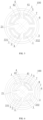
FIG. 1 is a schematic cross-sectional view where an outer periphery of each cable core of a liquid-cooled cable of the present disclosure is coated with an insulating layer and a shielding structure, and an outer side of an external liquid cooling channel is provided with an inner sheath, a shielding structure, and an outer sheath layer. -
FIG. 2 is a schematic cross-sectional view where an outer periphery of each cable core of a liquid-cooled cable of the present disclosure is coated with an insulating layer and a shielding structure, and an outer side of an external liquid cooling channel is provided with a shielding structure and an outer sheath layer. -
FIG. 3 is a schematic cross-sectional view where an outer periphery of a cable core of a liquid-cooled cable of the present disclosure is coated with an insulating layer, and an outer side of an external liquid cooling channel is provided with a shielding structure and an outer sheath layer. -
FIG. 4 is a schematic cross-sectional view where an outer periphery of a cable core of a liquid-cooled cable of the present disclosure is coated with an insulating layer, and an outer side of an external liquid cooling channel is provided with an inner sheath, a shielding structure, and an outer sheath layer. -
FIG. 5 is a schematic cross-sectional view where an outer periphery of each cable core of a liquid-cooled cable of the present disclosure is coated with an insulating layer and a shielding structure, and an outer side of an external liquid cooling channel is provided with an outer sheath layer. -
FIG. 6 is a schematic cross-sectional view where an outer periphery of a cable core of a liquid-cooled cable of the present disclosure is coated with an insulating layer and a shielding structure, and an outer side of an external liquid cooling channel is provided with an inner sheath, a shielding structure, and an outer sheath layer. -
FIG. 7 is a schematic cross-sectional view where an outer periphery of a cable core of a liquid-cooled cable of the present disclosure is coated with an insulating layer and a shielding structure, and an outer side of an external liquid cooling channel is provided with a shielding structure and an outer sheath layer. -
FIG. 8 is a schematic cross-sectional view where multiple cable cores of a liquid-cooled cable of the present disclosure are disposed in a radial direction of the liquid-cooled cable, and an outer side of an external liquid cooling channel is provided with an inner sheath, a shielding structure, and an outer sheath layer. -
FIG. 9 is a schematic cross-sectional view where each cable core of a liquid-cooled cable of the present disclosure is in a shape of a semicircular fan, and an outer side of an external liquid cooling channel is provided with an inner sheath, a shielding structure, and an outer sheath layer. -
FIG. 10 is a schematic cross-sectional view where a liquid-cooled cable of the present disclosure includes a cable core, and an outer side of an external liquid cooling channel is provided with an inner sheath, a shielding structure, and an outer sheath layer. -
FIG. 11 is a schematic structural diagram of a first support structure being a strip plate-like body according to the present disclosure. -
FIG. 12 is a schematic cross-sectional view where two adjacent cable cores of a liquid-cooled cable of the present disclosure form a shape of a semicircular fan, and an outer side of an external liquid cooling channel is provided with an inner sheath, a shielding structure, and an outer sheath layer. - In order to provide a clearer understanding of the technical features, purpose and effect of the present disclosure, the specific implementations of the present disclosure are described with reference to the accompanying drawings.
- The specific implementations of the present disclosure described herein are solely for explaining the purpose of the present disclosure and should not be construed in any way as limiting the present disclosure. Referring to the concept of the present disclosure, persons of ordinary skill can conceive of any possible variations based on the present disclosure, and these should be considered as within the scope of the present disclosure. It should be noted that when a component is referred to as being "disposed on" another component, it may be directly disposed on the another component, or there may be intermediary components present. When a component is deemed as being "connected to" another component, it may be directly connected to the another component, or there may be intermediary components present. The terms "mount", "join", and "connect" should be broadly interpreted. For example, they can refer to mechanical or electrical connection, internal communication of two components, direct connection, or indirect connection through an intermediary medium. For persons of ordinary skill in the art, the specific meanings of the above terms can be understood based on the specific circumstances. The terms "vertical", "horizontal", "up", "down", "left", "right", and similar expressions used in this embodiment are solely for explanatory purposes and do not indicate the only implementation.
- Unless otherwise defined, all technical and scientific terms used herein shall have the same meanings as commonly understood by those skilled in the art to which this application pertains. The terms used in the embodiment of this application are merely intended to describe specific embodiments but not intended to limit this application. The term "and/or" used herein includes any and all combinations of one or more associated items listed.
- As shown in
FIGs. 1 to 12 , the present disclosure provides a liquid-cooledcable 100, including a liquid cooling channel and at least one set ofcable cores 1 with a cross section in a shape of fan. The liquid cooling channel includes an internalliquid cooling channel 2, an externalliquid cooling channel 3, and at least one set of connectingchannels 4. The externalliquid cooling channel 3 communicates with the internalliquid cooling channel 2 via theconnecting channels 4, and a cooling medium flows in the liquid cooling channel. Thecable cores 1 are disposed at an outer periphery of the internalliquid cooling channel 2 and an inner periphery of the externalliquid cooling channel 3, and the connectingchannels 4 are disposed at a radial direction of the liquid-cooled cable and separate thecable cores 1. The internalliquid cooling channel 2 and the externalliquid cooling channel 3 are made of a highly conductive material. - In the liquid-cooled cable provided by present disclosure, the liquid cooling channels are increased inside and outside the cable cores, maximizing the cooling effect of the cable, so as to enhancing the flow carrying capacity of the cable and prolonging the service life.
- By arranging the connecting
channel 4, the cross section around the fan-shaped cable core 1 in the vertical direction may be liquid cooling, maximizing the cooling effect of the cable, so as to enhancing the flow carrying capacity of the cable and prolonging the service life. - In the liquid-cooled cable provided by the present disclosure, the cable core is configured into the shape of a fan, with each fan-shaped cable core surrounding the outer wall of a circular internal liquid cooling channel. Compared with the arrangement where the circular cable cores with the same cross-section area surround the outer wall of the internal liquid cooling channel, that the fan-shaped cable cores surround an outer wall of the circular internal liquid cooling channel obtains a smaller cable diameter and facilitates production of miniaturized cables, cable weight reduction, storage and management, and cable movement.
- In specific embodiments, it is assumed that a radius of the circular internal liquid cooling channel is r, and four fan-shaped cable cores whose radii are all 2r and angle radians are all 90° surround an outer wall of the internal liquid cooling channel to form a circular ring area of
S 1. According to a formula S=[(2r)2-r2]π, the calculation yields that the area of each fan-shaped cable core S2=[(2r)2-r2]π/4=0.25[(2r)2-r2]π. If the cross-sectional area of the circular cable core is made equal to S2, the radius of the circular cable core is obtained: R2=0.25[(2r)2-r2]π/π=0.75r2, so R=0.866r, and the diameter d=1.732r. Therefore, if the circular cable cores with the same cross-sectional area surround an outer wall of a circular internal liquid cooling tube, the cable radius is the distance from the central axis of the circular internal liquid cooling pipe to the farthest point on the circular wire core from the central axis of the liquid cooling pipe r+d=r+1.732r=2.732r. For the cable configured by fan-shaped cable cores with the same cross-sectional area surround the outer wall of a circular internal liquid cooling tube, the cable radius is the distance from the central axis of the circular internal liquid cooling pipe to the farthest point on the circular wire core from the central axis of the liquid cooling pipe 2r. Thus, it can be known that compared with the arrangement where the circular cable cores with the same cross-section area surround the outer wall of the internal liquid cooling channel, that the fan-shaped cable cores surround an outer wall of the circular internal liquid cooling channel obtains a smaller cable diameter. - The material of the liquid cooling channel includes one or more of polyvinyl chloride, polyethylene, polyamide, polytetrafluoroethylene, tetrafluoroethylene/hexafluoropropylene copolymer, ethylene/tetrafluoroethylene copolymer, polypropylene, polyvinylidene fluoride, polyurethane, polyterephthalic acid, polyurethane elastomer, styrene block copolymer, perfluoroalkoxyalkane, chlorinated polyethylene, polyphenylene sulphide, polystyrene, silicone rubber, crosslinked polyolefin, ethylene propylene rubber, ethylene/vinyl acetate copolymer, neoprene rubber, natural rubber, styrenebutadiene rubber, nitrile butadiene rubber, butadiene rubber, isoprene rubber, ethylenepropylene rubber, chloroprene rubber, butyl rubber, fluoro rubber, polyurethane rubber, polyacrylate rubber, chlorosulphonated polyethylene rubber, epichlorohydrin rubber, chlorinated polyethylene rubber, chlorosulphur rubber, styrene butadiene rubber, butadiene rubber, hydrogenated nitrile rubber, polysulfide rubber, cross-linked polyethylene, polycarbonate, polysulfone, polyphenylene ether, polyester, phenolic resin, urea-formaldehyde, styrene-acrylonitrile copolymer, polymethylmethacrylate, and polyoxymethylene resin.
- In specific embodiments, the cooling medium may be selected from one or more of castor oil, coconut oil, corn oil, cottonseed oil, flaxseed oil, olive oil, palm oil, peanut oil, grape seed oil, rapeseed oil, safflower oil, sunflower oil, soybean oil, a plant oil high-oleic variant, decen-4-oic acid, decenoic acid, lauric acid, epirubicin, tetradecenoic acid, whale wax acid, crude oil acid, palm oil acid, celery acid, oleic acid, octadecenoic acid, codenoic acid, giant whale acid, whale wax acid, erucic acid, and neurological acid, glycerin, transformer oil, axle oil, internal combustion engine oil, and compressor oil. An additive may be added into a cooling oil, and is selected from one or more of antioxidant, pour point depressant, corrosion inhibitor, antimicrobial agent, and viscosity modifier. The cooling oil possesses a sensitive heat balancing capability, exceptional heat conductivity, and an extraordinarily wide operating temperature range, precludes boiling and vaporization, maintains a micro-pressure of a cooling system, requires no antifreeze in a low-temperature environment, avoids corrosion damage such as cavitation, scaling, and electrolysis, and has other advantages. In specific embodiment, as long as the cooling liquid can cool the cable, it falls into the protection scope of the present disclosure and is not particularly limited herein.
- Further, as shown in
FIGs. 1 to 10 , the externalliquid cooling channel 3 includes afirst tube body 31 and asecond tube body 32. Thefirst tube body 31 sleeves thesecond tube body 32. The externalliquid cooling channel 3 further includes at least one first support structure and the first support structure is connected to an inner wall of the first tube body and an outer wall of the second tube body. The first support structure can ensure the stability of the externalliquid cooling channel 3 and smooth flowing of the cooling liquid in the externalliquid cooling channel 3. - Further, as shown in
FIGs. 1 to 10 , each of the connectingchannels 4 has a first viahole 41 and a second viahole 42 at two ends, the first viahole 41 runs through a tube wall of thesecond tube body 32, and the second viahole 42 runs through a tube wall of the internalliquid cooling channel 2. This can achieve communication between the internalliquid cooling channel 2 and the externalliquid cooling channel 3. The present disclosure does not particularly limit the connection manner of the connectingchannel 4 provided that the internalliquid cooling channel 2 communicates with the externalliquid cooling channel 3. - Further, as shown in
FIG. 11 , each first support structure is a plurality of sets ofcolumnar structures 331; and/or each first support structure is a strip plate-like body 332, and the strip plate-like body 332 is provided with a throughhole 333. With the arrangement of the plurality of sets ofcolumnar structures 331 and/or the strip plate-like body 332 with the throughhole 333, the structural stability of the externalliquid cooling channel 3 is increased, and realize the internal communication inside the externalliquid cooling channel 3, such that the cooling medium is not limited to flow through the entire externalliquid cooling channel 3. - Further, each of the connecting
channels 4 has two sets of side walls, and the two sets of side walls rotate around a central axis of the internal liquid cooling channel; or the two sets of side walls are parallel to the central axis of the internal liquid cooling channel. The arrangement manner of the two sets of side walls of each connectingchannel 4 is not limited particularly, provided that the production and user requirements are met. - Further, as shown in
FIGs. 1 to 7 , an outer periphery of at least onecable core 1 is sleeved with an insulatinglayer 5. The outer periphery of thecable core 1 being sleeved with the insulatinglayer 5 can protect thecable core 1 while enhancing the safety of the liquid-cooled cable during use. - In specific embodiments, the insulating layer includes one or more of polyvinyl chloride, polyethylene, polyamide, polytetrafluoroethylene, tetrafluoroethylene/hexafluoropropylene copolymer, ethylene/tetrafluoroethylene copolymer, polypropylene, polyvinylidene fluoride, polyurethane, polyterephthalic acid, polyurethane elastomer, styrene block copolymer, perfluoroalkoxyalkane, chlorinated polyethylene, polyphenylene sulphide, polystyrene, silicone rubber, crosslinked polyolefin, ethylene propylene rubber, ethylene/vinyl acetate copolymer, neoprene rubber, natural rubber, styrenebutadiene rubber, nitrile butadiene rubber, butadiene rubber, isoprene rubber, ethylenepropylene rubber, chloroprene rubber, butyl rubber, fluoro rubber, polyurethane rubber, polyacrylate rubber, chlorosulphonated polyethylene rubber, epichlorohydrin rubber, chlorinated polyethylene rubber, chlorosulphur rubber, styrene butadiene rubber, butadiene rubber, hydrogenated nitrile rubber, polysulfide rubber, cross-linked polyethylene, polycarbonate, polysulfone, polyphenylene ether, polyester, phenolic resin, urea-formaldehyde, styrene-acrylonitrile copolymer, polymethylmethacrylate, and polyoxymethylene resin.
- Further, as shown in
FIG. 8 ,multiple cable cores 1 are arranged in a radial direction of the liquid-cooled cable. In specific embodiment, whenmultiple cable cores 1 are arranged in the radial direction of the liquid-cooled cable, in a case of keeping the cross-sectional area of eachcable core 1 and the quantity of thecable cores 1 unchanged, compared with separately arrangingcable cores 1 with the same cross-sectional area in the radial direction of the liquid-cooled cable, arranging themultiple cable cores 1 in the radial direction of the liquid-cooled cable allows for a smaller farthest distance from thecable core 1 to the central axis of the liquid-cooled cable and reduces the cross-sectional area of the liquid-cooled cable, facilitating use and increasing the application scenarios. - In specific embodiment, when the
multiple cable cores 1 are arranged in the radial direction of the liquid-cooled cable, the insulatinglayer 5 should be additionally disposed on an outer side of thecable core 1, ensuring insulation between each two of themultiple cable cores 1 disposed radially without communication. - In specific embodiment, when the
multiple cable cores 1 are arranged in the radial direction of the liquid-cooled cable, a liquid cooling channel may be disposed between thecable cores 1 disposed radially, thus further ensuring the effect of cooling the cable. - Further, as shown in
FIGs. 1 to 10 , the liquid-cooledcable 100 further includes anouter sheath layer 6, and theouter sheath layer 6 is disposed at an outermost periphery of the liquid-cooled cable. Theouter sheath layer 6 can effectively protect its internal structure therein and prolong the service life of the liquid-cooled cable. - Further, as shown in
FIGs. 1 to 10 , the liquid-cooledcable 100 further includes a shieldingstructure 7, and an outer periphery of thefirst tube body 31 is sleeved with the shieldingstructure 7; and/or an outer periphery of the at least onecable core 1 is sleeved with an insulatinglayer 5, and an outer periphery of the at least one insulatinglayer 5 is sleeved with the shieldingstructure 7. The shieldingstructure 7 can conduct part of heat outward to ensure the effect of cooling the cable core, and isolate the electromagnetic field in thecable core 1 from the external electromagnetic field to reduce interference with the surroundings. - In this embodiment, the shielding
structure 7 is a metal shielding layer and configured to radially conduct thermal energy outwards and reduce interference with the surroundings. The shieldingstructure 7 may be a metal strip, a metal wire, a conductive plastic, or a conductive rubber, and the shieldingstructure 7 is made through one or more of processes such as coil wrapping, longitudinal wrapping, braiding, helical wrapping, metal armoring, or extrusion. - Further, the shielding
structure 7 sleeving the outer side of the insulatinglayer 5 of thecable core 1 or the shieldingstructure 7 sleeving the outer periphery of thefirst tube body 31 has a thickness greater than or equal to 38 µm, and thecorresponding shielding structure 7 sleeving the outer periphery of thefirst tube body 31 or shieldingstructure 7 sleeving the outer side of the insulatinglayer 5 of thecable core 1 has a thickness smaller than 38 µm. - The thickness of the shielding
structure 7 sleeving the outer side of the insulatinglayer 5 of thecable core 1 or the shieldingstructure 7 sleeving the outer periphery of thefirst tube body 31, and the thickness of thecorresponding shielding structure 7 sleeving the outer periphery of thefirst tube body 31 or shieldingstructure 7 sleeving the outer side of the insulatinglayer 5 of thecable core 1 may be determined based on requirements and limited times experiments. Exemplarily, the thickness of one shielding sleeve is greater than or equal to 38 µm, and the other corresponding shielding sleeve is less than 38 µm. To verify the effect of the thickness of the shielding sleeve on the flow carrying capability of the shielding sleeve, the inventor separately selects different thicknesses for the shieldingstructure 7 sleeving the outer side of the insulatinglayer 5 of thecable core 1 and the shieldingstructure 7 sleeving the outer periphery of thefirst tube body 31, to separately test the shielding performance of liquid-cooled cables. In this embodiment, an ideal shielding performance value of the liquid-cooled cable is greater than 40 dB. - In a specific embodiment, the insulating
layer 5 and the shieldingstructure 7 are both disposed outside eachcable core 1 for testing the shielding performance value of the liquid-cooled cable. - The method for testing a shielding performance value: A tester outputs a signal value (which is test value 2) to the liquid-cooled cable, a detection apparatus is disposed outside the liquid-cooled cable, and the detection apparatus detects a signal value (which is test value 1). Shielding performance value=test value 2-
test value 1.Table 1: Effect of a thickness of a shielding structure 7 sleeving an outer side of an insulatinglayer 5 of acable core 1 or a shieldingstructure 7 sleeving an outer periphery of afirst tube body 31 on shielding performanceTest parameter Frequency greater than 5 MHz Thickness of the shielding structure 7 sleeving the outer side of the insulatinglayer 5 of thecable core 1 or the shieldingstructure 7 sleeving the outer periphery of the first tube body 31 (µm)8 18 28 38 48 58 68 78 88 Shielding performan ce value (dB) 24 31 35 37 44 46 50 53 57 Test parameter Frequency less than 5 MHz Thickness of the shielding structure 7 sleeving the outer side of the insulatinglayer 5 of thecable core 1 or shieldingstructure 7 sleeving the outer periphery of the first tube body 31 (µm)8 18 28 38 48 58 68 78 88 Shielding performan ce value (dB) 53 47 43 38 36 33 28 25 21 - It can be seen from Table 1 that when the test frequency is greater than 5 MHz, the thickness of the shielding
structure 7 sleeving the outer side of the insulatinglayer 5 of thecable core 1 or the shieldingstructure 7 sleeving the outer periphery of thefirst tube body 31 is less than 38 µm, and the shielding performance value of the liquid-cooled cable is qualified. When the test frequency is less than 5 MHz, the thickness of the shieldingstructure 7 sleeving the outer side of the insulatinglayer 5 of thecable core 1 or the shieldingstructure 7 sleeving the outer periphery of thefirst tube body 31 is greater than 38 µm, and the shielding performance value of the liquid-cooled cable is qualified. Therefore, as the shieldingstructure 7 sleeving the outer side of the insulatinglayer 5 of thecable core 1 or the shieldingstructure 7 sleeving the outer periphery of thefirst tube body 31 respectively use different thicknesses, the interference signals across all frequencies can be shielded, thus ensuring the shielding performance of the liquid-cooled cable. Therefore, the inventor sets the thickness of the shieldingstructure 7 sleeving the outer side of the insulatinglayer 5 of thecable core 1 or the shieldingstructure 7 sleeving the outer periphery of thefirst tube body 31 to be greater than or equal to 38 µm, and thecorresponding shielding structure 7 sleeving the outer periphery of thefirst tube body 31 or shieldingstructure 7 sleeving the outer side of the insulatinglayer 5 of thecable core 1 to be less than 38 µm. - Further, as shown in
FIGs. 1 ,4 ,6 ,8 ,9, and 10 , the liquid-cooledcable 100 further includes aninner sheath 8, the outer periphery of thefirst tube body 31 is sleeved with theinner sheath 8, and the outer periphery of theinner sheath 8 is sleeved with a shieldingstructure 7. - The arrangement of the
inner sheath 8 can protect the liquid cooling channel, avoiding damage to the liquid cooling channel. Meanwhile, arranging the shieldingstructure 7 on the outer side of theinner sheath 8 can improve the stability of the shieldingstructure 7, avoiding damage to the shieldingstructure 7. - The material of the inner sheath or the outer sheath includes one or more of polyvinyl chloride, polyethylene, polyamide, polytetrafluoroethylene, tetrafluoroethylene/hexafluoropropylene copolymer, ethylene/tetrafluoroethylene copolymer, polypropylene, polyvinylidene fluoride, polyurethane, polyterephthalic acid, polyurethane elastomer, styrene block copolymer, perfluoroalkoxyalkane, chlorinated polyethylene, polyphenylene sulphide, polystyrene, silicone rubber, crosslinked polyolefin, ethylene propylene rubber, ethylene/vinyl acetate copolymer, neoprene rubber, natural rubber, styrenebutadiene rubber, nitrile butadiene rubber, butadiene rubber, isoprene rubber, ethylenepropylene rubber, chloroprene rubber, butyl rubber, fluoro rubber, polyurethane rubber, polyacrylate rubber, chlorosulphonated polyethylene rubber, epichlorohydrin rubber, chlorinated polyethylene rubber, chlorosulphur rubber, styrene butadiene rubber, butadiene rubber, hydrogenated nitrile rubber, polysulfide rubber, cross-linked polyethylene, polycarbonate, polysulfone, polyphenylene ether, polyester, phenolic resin, urea-formaldehyde, styrene-acrylonitrile copolymer, polymethylmethacrylate, and polyoxymethylene resin.
- Further, the internal
liquid cooling channel 2 further includes at least one set ofsecond support structures 21, thesecond support structure 21 supports and connects an inner wall of the internalliquid cooling channel 2, thesecond support structure 21 is a strip plate-like body 332, and the strip plate-like body is provided with a plurality of sets of throughholes 333; and/or thesecond support structure 21 is a plurality of sets of columnar structures. - In a specific embodiment, the arrangement of the
second support structure 21 prevents an external force from enabling the inner walls of the internal liquid cooling channel to contact each other, where such contact causes the internal liquid cooling channel to be blocked and thus the cooling medium cannot flow in the internal liquid cooling channel. - Further, a ratio of an inner cavity cross-sectional area of the internal
liquid cooling channel 2 to a cross-sectional area sum of thecable cores 1 is 2% to 60%. - To verify the effect of the ratio of the inner cavity cross-sectional area of the internal
liquid cooling channel 2 to a cross-sectional area sum of thecable cores 1 on temperature rising of the liquid-cooled cable, the inventor selects the liquid-cooled cables with the same structure, externalliquid cooling channels 3 with the same cross-sectional area, and matched runningcable cores 1 with the same cross-sectional area sum. During test, liquid-cooled cables with different ratios of inner cavity cross-sectional areas of internalliquid cooling channels 2 to a cross-sectional area sum of thecable cores 1 are used for temperature rising test. - The method for temperature rising test: In a closed environment, liquid-cooled cables with different ratios of inner cavity cross-sectional areas of the internal
liquid cooling channels 2 to the cross-sectional area sum ofcable cores 1 are used, the same current is conducted, and the temperature of the liquid-cooled cable before energization and the temperature of the liquid-cooled cable when the temperature is stable after energization are recorded to take an absolute value by difference. In this embodiment, a temperature rise value less than 50 k is qualified.Table 2: Effect of a ratio of an inner cavity cross-sectional area of an internal liquid cooling channel 2 to a cross-sectional area sum ofcable cores 1 on temperature rising of a liquid-cooled cableRatio of inner cavity cross-sectional area of internal liquid cooling channel 2 to cross-sectional area sum of cable cores 1 (%)0.5 1 2 16 23 32 45 49 56 60 68 72 Temperature rise of liquid-cooled cable (K) 58 52 48 44 40 37 33 29 25 21 20 20 - It can be seen from Table 2 that when the ratio of the inner cavity cross-sectional area of the internal
liquid cooling channel 2 to the cross-sectional area sum of thecable cores 1 is less than 2%, because the internal cross-sectional area of the internalliquid cooling channel 2 is small and the cooling medium flowing in the internalliquid cooling channel 2 has a small volume and cannot timely take away the heat generated by the cable cores due to current conduction, the liquid-cooled cable has a high temperature and the temperature rise value of the liquid-cooled cable is greater than 50 k, the temperature rise value is unqualified. When the ratio of the inner cavity cross-sectional area of the internalliquid cooling channel 2 to the cross-sectional area sum of thecable cores 1 is greater than or equal to 2%, the cooling medium in the internalliquid cooling channel 2 has a large volume percentage and can timely take away the heat generated by the cable cores due to current conduction, and the temperature rise value of the liquid-cooled cable is less than 50 k. However, as the ratio of the inner cavity cross-sectional area of the internalliquid cooling channel 2 to the cross-sectional area sum of thecable cores 1 continuously increases to 60%, the temperature rise value decreases and becomes stable, no longer showing the decrease tendency. However, in this case, the large internal cross-sectional area of the internalliquid cooling channel 2 results in a large outer diameter of the liquid-cooled cable, the outer diameter of the liquid-cooled cable at this moment is larger than an outer diameter of a normal cable that conducts the same current and has no liquid cooling channel, and thus using liquid-cooled cables has no practical optimization value. So, the inventor selects the ratio of the inner cavity cross-sectional area of the internalliquid cooling channel 2 to the cross-sectional area sum of thecable cores 1 to be 2% to 60%. - Further, a ratio of an inner cavity cross-sectional area of the external
liquid cooling channel 3 to the cross-sectional area sum of thecable cores 1 is 2% to 60%. - To verify the effect of the ratio of the inner cavity cross-sectional area of the external
liquid cooling channel 3 to the cross-sectional area sum of thecable cores 1 on temperature rising of the liquid-cooled cable, the inventor selects the liquid-cooled cables with the same structure, internalliquid cooling channels 2 with the same cross-sectional area, and matched running cable cores with the same cross-sectional area sum. During test, liquid-cooled cables with different ratios of inner cavity cross-sectional areas of externalliquid cooling channels 3 to a cross-sectional area sum of thecable cores 1 are used for temperature rising test. - The method for temperature rising test: In a closed environment, liquid-cooled cables with different ratios of inner cavity cross-sectional areas of the external
liquid cooling channels 3 to the cross-sectional area sum ofcable cores 1 are used, the same current is conducted, and the temperature of the liquid-cooled cable before energization and the temperature of the liquid-cooled cable when the temperature is stable after energization are recorded to take an absolute value by difference. In this embodiment, a temperature rise value less than 50 k is qualified.Table 3: Effect of a ratio of an inner cavity cross-sectional area of an external liquid cooling channel 3 to a cross-sectional area sum ofcable cores 1 on temperature rising of a liquid-cooled cableRatio of inner cavity cross-sectional area of external liquid cooling channel 3 to cross-sectional area sum of cable cores 1 (%)0.5 1 2 19 24 35 44 51 56 60 69 75 Temperature rise of liquid-cooled cable (K) 58 52 48 44 40 37 33 29 25 21 20 20 - It can be seen from Table 3 that when the ratio of the inner cavity cross-sectional area of the external
liquid cooling channel 3 to the cross-sectional area sum of thecable cores 1 is less than 2%, because the internal cross-sectional area of the externalliquid cooling channel 3 is small and the cooling medium flowing therein has a small volume and cannot timely take away the heat generated by the cable cores due to current conduction, the liquid-cooled cable has a high temperature and the temperature rise value of the liquid-cooled cable is greater than 50 k, unqualified. When the ratio of the inner cavity cross-sectional area of the externalliquid cooling channel 3 to the cross-sectional area sum of thecable cores 1 is greater than or equal to 2%, the cooling medium in the externalliquid cooling channel 3 has a large volume percentage and can timely take away the heat generated by thecable cores 1 due to current conduction, and the temperature rise value of the liquid-cooled cable is less than 50 k. However, as the ratio of the inner cavity cross-sectional area of the externalliquid cooling channel 3 to the cross-sectional area sum of thecable cores 1 continuously increases to 60%, the temperature rise value decreases and becomes stable, no longer showing the decrease tendency. Furthermore, in this case, the large internal cross-sectional area of the externalliquid cooling channel 3 results in a large outer diameter of the liquid-cooled cable, the outer diameter of the liquid-cooled cable at this moment is larger than an outer diameter of a normal cable that conducts the same current and has no liquid cooling channel, and thus using liquid-cooled cables has no practical optimization value. Further, the inventor selects the ratio of the inner cavity cross-sectional area of the externalliquid cooling channel 3 to the cross-sectional area sum of thecable cores 1 to be 2% to 60%. - Further, a ratio of a distance between two side walls of the connecting
channel 4 to a circumference of the internalliquid cooling channel 2 is 5% to 45%. - To verify the effect of the ratio of a distance between two side walls of the connecting
channel 4 to the circumference of the internalliquid cooling channel 2 on temperature rising of the liquid-cooled cable, the inventor uses the liquid-cooled cables with the same structure. During test, these liquid-cooled cables, having different ratios of the distances between two side walls of the connectingchannels 4 to circumferences of the internalliquid cooling channels 2, are used for temperature rising test. - The method for temperature rising test: In a closed environment, liquid-cooled cables, having different ratios of the distances between two side walls of the connecting
channels 4 to circumferences of the internalliquid cooling channels 2 are used, the same current is conducted, and the temperature of the liquid-cooled cable before energization and the temperature of the liquid-cooled cable when the temperature is stable after energization are recorded to take an absolute value by difference. In this embodiment, a temperature rise value less than 50 k is qualified.Table 4: Effect of a ratio of a distance between two side walls of a connecting channel 4 to a circumference of an internalliquid cooling channel 2 on temperature rising of a liquid-cooled cableRatio of distance between two side walls of connecting channel 4 to circumference of internal liquid cooling channel 2 (%)1 3 5 9 14 22 28 34 39 45 60 71 Temperature rise of liquid-cooled cable (K) 57 54 49 43 39 35 33 28 25 20 19 19 - It can be seen from Table 4 that when the ratio of the distance between two side walls of the connecting
channel 4 to the circumference of the internalliquid cooling channel 2 is less than 5%, because the connectingchannel 4 cannot enable good flowing of the cooling medium between the internalliquid cooling channel 2 and the externalliquid cooling channel 3 and the cooling medium flowing in the connectingchannel 4 has a small volume and cannot timely take away the heat generated by thecable cores 1 on two sides of the connectingchannel 4 due to current conduction, the liquid-cooled cable has a high temperature and the temperature rise value of the liquid-cooled cable is greater than 50 k, the temperature rise value is unqualified. When the ratio of the distance between two side walls of the connectingchannel 4 to the circumference of the internalliquid cooling channel 2 is greater than or equal to 45%, good flowing of the cooling medium between the internalliquid cooling channel 2 and the externalliquid cooling channel 3 can be enabled, the cooling medium in the connectingchannel 4 has a large volume percentage and can timely take away the heat generated by thecable cores 1 on two sides of the connectingchannel 4 due to current conduction, and the temperature rise value of the liquid-cooled cable is less than 50 k. However, as the ratio of the distance between two side walls of the connectingchannel 4 to the circumference of the internalliquid cooling channel 2 increases to 45%, the temperature rise value decreases and becomes stable, no longer showing the decrease tendency. In this case, continuous increase in the ratio is meaningless. Therefore, the inventor needs to set the ratio of the distance between two side walls of the connectingchannel 4 to the circumference of the internalliquid cooling channel 2 to be 5% to 45%. - Further, a ratio of a circumferential total width of the first support structure to a circumference of the external
liquid cooling channel 3 is 4% to 54%. - When the first support structure is a strip plate-
like body 332, to verify the effect of the ratio of the circumferential total width of the first support structure to the circumference of the externalliquid cooling channel 3 on temperature rising of the liquid-cooled cable, the inventor uses the liquid-cooled cables with the same structure. During test, these liquid-cooled cables, having different ratios of circumferential total widths of the first support structures to circumferences of externalliquid cooling channels 3, are used for temperature rising test. - The method for temperature rising test: In a closed environment, liquid-cooled cables with different ratios of circumferential total widths of the first support structures to circumferences of external liquid cooling channels are used, the same current is conducted, and the temperature of the liquid-cooled cable before energization and the temperature of the liquid-cooled cable when the temperature is stable after energization are recorded to take an absolute value by difference. In this embodiment, the temperature rise value less than 50 k is qualified while it should be ensured that the external liquid cooling channel does not deform. If the external
liquid cooling channel 3 deforms, the value is also unqualified.Table 5: Effect of a ratio of a circumferential total width of a first support structure to a circumference of an external liquid cooling channel 3 on temperature rising of a liquid-cooled cableRatio of circumferential total width of the first support structure to circumference of external liquid cooling channel 3 (%) 1 2 4 21 27 31 38 44 49 54 61 73 Temperature rise of liquid-cooled cable (K) 0 0 24 27 29 31 34 38 42 49 57 71 Whether the external liquid cooling channel 3 deformsYes Yes No No No No No No No No No No - It can be seen from Table 5 that when the ratio of the circumferential total width of the first support structure to the circumference of the external
liquid cooling channel 3 is less than 4%, because the externalliquid cooling channel 3 deforms, it is unnecessary to conduct the temperature rise test on it. When the ratio of the circumferential total width of the first support structure to the circumference of an externalliquid cooling channel 3 is greater than 54%, because the percentage of the first support structure is large, the percentage of the cooling medium flowing in the externalliquid cooling channel 3 is small, and the heat generated by the cable cores on two sides of the externalliquid cooling channel 3 due to current conduction cannot be taken away, the temperature of the liquid-cooled cable is high and the temperature rise value of the liquid-cooled cable is greater than 50 K, unqualified. Therefore, the inventor selects the ratio of the circumferential total width of the first support structure to the circumference of an externalliquid cooling channel 3 to be 4% to 54%. - Further, a ratio of a circumferential total width of the
second support structure 21 to an inner diameter of the internalliquid cooling channel 2 is 3% to 20%. - When the
second support structure 21 is a strip plate-like body 332, to verify the effect of the ratio of the circumferential total width of thesecond support structure 21 to the inner diameter of the internalliquid cooling channel 2 on temperature rising of the liquid-cooled cable, the inventor uses the liquid-cooled cables with the same structure. During test, these liquid-cooled cables, having different ratios of circumferential widths of thesecond support structures 21 to inner diameters of internalliquid cooling channels 2, are used for temperature rising test. - The method for temperature rising test: In a closed environment, liquid-cooled cables with different ratios of circumferential total widths of the
second support structures 21 to inner diameters of internal liquid cooling channels are used, the same current is conducted, and the temperature of the liquid-cooled cable before energization and the temperature of the liquid-cooled cable when the temperature is stable after energization are recorded to take an absolute value by difference. In this embodiment, the temperature rise value less than 50 k is qualified while it should be ensured that the internalliquid cooling channel 2 does not deform. If the internalliquid cooling channel 2 deforms, the value is also unqualified.Table 6: Effect of a ratio of a circumferential total width of a second support structure 21 to an inner diameter of an internalliquid cooling channel 2 on temperature rising of a liquid-cooled cableRatio of circumferential total width of second support structure 21 to inner diameter of internal liquid cooling channel 2 (%)1 2 3 5 7 10 12 15 18 20 25 45 Temperature rise of liquid-cooled cable (K) 19 20 25 27 29 31 33 39 43 48 55 69 - It can be seen from Table 6 that when the ratio of the circumferential width of the
second support structure 21 to the inner diameter of the internalliquid cooling channel 2 is less than 3%, although the temperature rise value of the liquid-cooled cable is less than 50 k, the ratio of the circumferential width of thesecond support structure 21 to the inner diameter of the internalliquid cooling channel 2 is excessively small, resulting in difficult production. When the ratio of the circumferential total width of thesecond support structure 21 to the inner diameter of the internalliquid cooling channel 2 is greater than 20% , the temperature rise value of the liquid-cooled cable is greater than 50 K, so the temperature rise value is unqualified. Therefore, the ratio of the circumferential width of thesecond support structure 21 to the inner diameter of the internal liquid cooling channel is 3% to 20%. - Further, the liquid-cooled
cable 100 further includes a liquid cooling circulation pump. The liquid cooling circulation pump communicates with the liquid cooling channel via a communication tube, and the liquid cooling circulation pump is configured to circulate and cool the cooling medium in the liquid cooling channel. The cooling medium is used to take away the heat generated by thecable cores 1 during operation, and the liquid cooling circulation pump can quickly dissipate heat from the cooling medium to the external environment, ensuring the normal use of the liquid-cooled cable. - The specific embodiments are as follows:
- As shown in
FIG. 1 , an outer periphery of each cable core of a liquid-cooled cable of the present disclosure is coated with an insulating layer and a shielding structure, and an outer side of an external liquid cooling channel is provided with an inner sheath, a shielding structure, and an outer sheath layer. - As shown in
FIG. 2 , an outer periphery of each cable core of a liquid-cooled cable of the present disclosure is coated with an insulating layer and a shielding structure, and an outer side of an external liquid cooling channel is provided with a shielding structure and an outer sheath layer. - As shown in
FIG. 3 , an outer periphery of a cable core of a liquid-cooled cable of the present disclosure is coated with an insulating layer, and an outer side of an external liquid cooling channel is provided with a shielding structure and an outer sheath layer. - As shown in
FIG. 4 , an outer periphery of a cable core of a liquid-cooled cable of the present disclosure is coated with an insulating layer, and an outer side of an external liquid cooling channel is provided with an inner sheath, a shielding structure, and an outer sheath layer. - As shown in
FIG. 5 , an outer periphery of each cable core of a liquid-cooled cable of the present disclosure is coated with an insulating layer and a shielding structure, and an outer side of an external liquid cooling channel is provided with an outer sheath layer. - As shown in
FIG. 6 , an outer periphery of a cable core of a liquid-cooled cable of the present disclosure is coated with an insulating layer and a shielding structure, and an outer side of an external liquid cooling channel is provided with an inner sheath, a shielding structure, and an outer sheath layer. - As shown in
FIG. 7 , an outer periphery of a cable core of a liquid-cooled cable of the present disclosure is coated with an insulating layer and a shielding structure, and an outer side of an external liquid cooling channel is provided with a shielding structure and an outer sheath layer. - As shown in
FIG. 8 , multiple cable cores of a liquid-cooled cable of the present disclosure are disposed in a radial direction of the liquid cooling cable, and an outer side of an external liquid cooling channel is provided with an inner sheath, a shielding structure, and an outer sheath layer. - As shown in
FIG. 9 , each cable core of a liquid-cooled cable of the present disclosure is in a shape of a semicircular fan, and an outer side of an external liquid cooling channel is provided with an inner sheath, a shielding structure, and an outer sheath layer. - As shown in
FIG. 10 , a liquid-cooled cable of the present disclosure includes a cable core, and an outer side of an external liquid cooling channel is provided with an inner sheath, a shielding structure, and an outer sheath layer. -
FIG. 12 is a schematic cross-sectional view where two adjacent cable cores of a liquid-cooled cable of the present disclosure form a shape of a semicircular fan, and an outer side of an external liquid cooling channel is provided with an inner sheath, a shielding structure, and an outer sheath layer. - Based on the foregoing description, the liquid-cooled cable in the present disclosure has the following beneficial effects:
In the liquid-cooled cable provided by present disclosure, the liquid cooling channels are increased inside and outside the cable cores, maximizing the cooling effect of the cables. The outer sheath layer can protect a structure therein. The cable cores in the liquid-cooled cable of the present disclosure have good heat dissipation effect, thus enhancing the flow carrying capacity of the cables and prolonging the service life. - The above descriptions are merely illustrative specific implementations of the present disclosure and are not intended to limit the scope of the present disclosure. Any equivalent changes and modifications made by those skilled in the art, without departing from the concept and principle of the present disclosure, should fall within the protection scope of the present disclosure.
Claims (17)
- A liquid-cooled cable, comprising a liquid cooling channel and at least one set of cable cores with a cross section in a shape of fan, wherein the liquid cooling channel comprises an internal liquid cooling channel, an external liquid cooling channel, and at least one set of connecting channels, the external liquid cooling channel communicates with the internal liquid cooling channel via the connecting channels, and a cooling medium flows in the liquid cooling channel; and the cable cores are disposed at an outer periphery of the internal liquid cooling channel and an inner periphery of the external liquid cooling channel, and the connecting channels are disposed at a radial direction of the liquid-cooled cable and separate the cable cores.
- The liquid-cooled cable according to claim 1, wherein the external liquid cooling channel comprises a first tube body and a second tube body; the first tube body sleeves the second tube body; and the external liquid cooling channel further comprises at least one first support structure, and the first support structure is connected to an inner wall of the first tube body and an outer wall of the second tube body.
- The liquid-cooled cable according to claim 2, wherein each of the connecting channels has a first via hole and a second via hole at two ends, the first via hole runs through a tube wall of the second tube body, and the second via hole runs through a tube wall of the internal liquid cooling channel.
- The liquid-cooled cable according to claim 2, wherein each first support structure is a plurality of sets of columnar structures; and/or each first support structure is a strip plate-like body, and the strip plate-like body is provided with a through hole.
- The liquid-cooled cable according to claim 1, wherein each of the connecting channels has two sets of side walls, and the two sets of side walls rotate around a central axis of the internal liquid cooling channel; or the two sets of side walls are parallel to the central axis of the internal liquid cooling channel.
- The liquid-cooled cable according to claim 1, wherein an outer periphery of at least one of the cable cores is sleeved with an insulating layer.
- The liquid-cooled cable according to claim 1, wherein the multiple cable cores are disposed in the radial direction of the liquid cooling cable.
- The liquid-cooled cable according to claim 1, wherein the liquid cooling cable further comprises an outer sheath layer, and the outer sheath layer is disposed at an outermost periphery of the liquid cooling cable.
- The liquid-cooled cable according to claim 2, wherein the liquid cooling cable further comprises a shielding structure, and an outer periphery of the first tube body is sleeved with the shielding structure; and/or an outer periphery of the at least one cable core is sleeved with an insulating layer, and an outer periphery of the at least one insulating layer is sleeved with the shielding structure.
- The liquid-cooled cable according to claim 9, wherein the liquid cooling cable further comprises an inner sheath, the outer periphery of the first tube body is sleeved with the inner sheath, and an outer periphery of the inner sheath is sleeved with the shielding structure.
- The liquid-cooled cable according to claim 1, wherein the internal liquid cooling channel further comprises at least one set of second support structures, the second support structure supports and connects an inner wall of the internal liquid cooling channel, the second support structure is a strip plate-like body, and the strip plate-like body is provided with a plurality of sets of through holes; and/or the second support structure is a plurality of sets of columnar structures.
- The liquid-cooled cable according to claim 1, wherein a ratio of an inner cavity cross-sectional area of the internal liquid cooling channel to a cross-sectional area sum of the cable cores is 2% to 60%.
- The liquid-cooled cable according to claim 1, wherein a ratio of an inner cavity cross-sectional area of the external liquid cooling channel to a cross-sectional area sum of the cable cores is 2% to 60%.
- The liquid-cooled cable according to claim 5, wherein a ratio of a distance between two side walls of the connecting channel to a circumference of the internal liquid cooling channel is 5% to 45%.
- The liquid-cooled cable according to claim 4, wherein a ratio of a circumferential total width of the first support structure to a circumference of the external liquid cooling channel is 4% to 54%.
- The liquid-cooled cable according to claim 11, wherein a ratio of a circumferential total width of the second support structure to an inner diameter of the internal liquid cooling channel is 3% to 20%.
- The liquid-cooled cable according to any one of claims 1 to 16, further comprising a liquid cooling circulation pump, wherein the liquid cooling circulation pump communicates with the liquid cooling channel via a communication tube, and the liquid cooling circulation pump is configured to circulate and cool the cooling medium in the liquid cooling channel.
Applications Claiming Priority (2)
| Application Number | Priority Date | Filing Date | Title |
|---|---|---|---|
| CN202111444463.3A CN114267486B (en) | 2021-11-30 | 2021-11-30 | Liquid cooling cable |
| PCT/CN2022/131367 WO2023098451A1 (en) | 2021-11-30 | 2022-11-11 | Liquid cooled cable |
Publications (2)
| Publication Number | Publication Date |
|---|---|
| EP4443447A1 true EP4443447A1 (en) | 2024-10-09 |
| EP4443447A4 EP4443447A4 (en) | 2025-03-12 |
Family
ID=80825891
Family Applications (1)
| Application Number | Title | Priority Date | Filing Date |
|---|---|---|---|
| EP22900256.3A Pending EP4443447A4 (en) | 2021-11-30 | 2022-11-11 | Liquid cooled cable |
Country Status (4)
| Country | Link |
|---|---|
| US (1) | US20250022633A1 (en) |
| EP (1) | EP4443447A4 (en) |
| CN (1) | CN114267486B (en) |
| WO (1) | WO2023098451A1 (en) |
Families Citing this family (7)
| Publication number | Priority date | Publication date | Assignee | Title |
|---|---|---|---|---|
| CN114267486B (en) * | 2021-11-30 | 2025-04-01 | 长春捷翼汽车科技股份有限公司 | Liquid cooling cable |
| CN115171962A (en) * | 2022-06-29 | 2022-10-11 | 长春捷翼汽车零部件有限公司 | Flat liquid cooling cable of multicore |
| CN115440430A (en) * | 2022-08-12 | 2022-12-06 | 长春捷翼汽车零部件有限公司 | Liquid cooling cable |
| CN116195010B (en) * | 2022-11-08 | 2024-05-17 | 远东电缆有限公司 | Liquid-cooled high-power charging cable for new energy automobile and production process thereof |
| CN116981224A (en) * | 2023-07-31 | 2023-10-31 | 深圳易瓦科技有限公司 | A liquid-cooled new energy vehicle charging gun |
| CN117316517B (en) * | 2023-10-26 | 2024-05-14 | 江苏天诚智能集团股份有限公司 | Energy power cooling cable |
| CN118866454B (en) * | 2024-09-27 | 2024-12-10 | 浙江启超电缆股份有限公司 | A self-cooling cable |
Family Cites Families (17)
| Publication number | Priority date | Publication date | Assignee | Title |
|---|---|---|---|---|
| SE429276B (en) * | 1978-12-21 | 1983-08-22 | Volvo Ab | WATER-COOLED COAXIAL CABLE |
| JP2003257260A (en) * | 2002-02-28 | 2003-09-12 | Tokyo Electric Power Co Inc:The | Superconducting cable and manufacturing method thereof |
| CN2762295Y (en) * | 2004-08-17 | 2006-03-01 | 毕耜超 | Cable with aluminium alloy water pipe for cooling |
| CN2817008Y (en) * | 2005-06-28 | 2006-09-13 | 宝胜科技创新股份有限公司 | Water-cooling cable of exterally and internally feeding water |
| CN201219802Y (en) * | 2008-06-12 | 2009-04-15 | 黄良英 | Dustproof ground cushion |
| CN201229802Y (en) * | 2008-07-22 | 2009-04-29 | 芜湖明远电线电缆有限责任公司 | Water cooling special electric cable |
| CN203433870U (en) * | 2013-08-19 | 2014-02-12 | 宝胜科技创新股份有限公司 | High-temperature resistant flexible intermediate frequency water-cooled cable |
| CN208385068U (en) * | 2018-08-09 | 2019-01-15 | 洛阳一缆电器有限公司 | A kind of adjacent layer reversed cable |
| CN109741871A (en) * | 2019-01-13 | 2019-05-10 | 朱昀 | A kind of control cable |
| CN209785622U (en) * | 2019-06-14 | 2019-12-13 | 江苏红云电缆有限公司 | Novel copper core power cable |
| EP3770925B1 (en) * | 2019-07-25 | 2023-12-27 | ABB E-mobility B.V. | Heavy-current charging cable for charging an electric vehicle |
| CN111696717A (en) * | 2020-06-26 | 2020-09-22 | 寇金臣 | Multi-core branch combination cable |
| CN111933346B (en) * | 2020-07-20 | 2024-12-13 | 国网江苏省电力有限公司淮安供电分公司 | A safe and environmentally friendly power cable with rapid heat dissipation |
| CN213303741U (en) * | 2020-11-24 | 2021-05-28 | 江苏新山峰电缆有限公司 | Cable capable of being cooled rapidly |
| CN216353537U (en) * | 2021-11-30 | 2022-04-19 | 长春捷翼汽车零部件有限公司 | Liquid cooling cable |
| CN114267486B (en) * | 2021-11-30 | 2025-04-01 | 长春捷翼汽车科技股份有限公司 | Liquid cooling cable |
| CN115440430A (en) * | 2022-08-12 | 2022-12-06 | 长春捷翼汽车零部件有限公司 | Liquid cooling cable |
-
2021
- 2021-11-30 CN CN202111444463.3A patent/CN114267486B/en active Active
-
2022
- 2022-11-11 US US18/714,465 patent/US20250022633A1/en active Pending
- 2022-11-11 EP EP22900256.3A patent/EP4443447A4/en active Pending
- 2022-11-11 WO PCT/CN2022/131367 patent/WO2023098451A1/en not_active Ceased
Also Published As
| Publication number | Publication date |
|---|---|
| EP4443447A4 (en) | 2025-03-12 |
| WO2023098451A1 (en) | 2023-06-08 |
| US20250022633A1 (en) | 2025-01-16 |
| CN114267486A (en) | 2022-04-01 |
| CN114267486B (en) | 2025-04-01 |
Similar Documents
| Publication | Publication Date | Title |
|---|---|---|
| US20250022633A1 (en) | Liquid-cooled cable | |
| US7840244B2 (en) | Superconducting cable | |
| CN219891954U (en) | Liquid cooling cable | |
| WO2024032773A1 (en) | Liquid-cooled cable | |
| EP2652754A1 (en) | High voltage electric cable | |
| CN115424764B (en) | Liquid cooling wire and liquid cooling cable | |
| US20250105540A1 (en) | Connector assembly having liquid cooling function, and vehicle | |
| CN113871066A (en) | Liquid-cooled flat cable and liquid-cooled flat cable mechanism | |
| CN220065255U (en) | cable | |
| US20080164048A1 (en) | Superconducting Cable | |
| CN216353537U (en) | Liquid cooling cable | |
| CN120674776B (en) | A radio frequency coaxial cable | |
| CN109741860B (en) | Adjustable high-power coaxial liquid cooling cable | |
| CN113053587B (en) | Preparation method of fireproof cable | |
| US7723616B2 (en) | Superconducting cable and DC transmission system incorporating the superconducting cable | |
| CN109767874B (en) | Coaxial refrigeration cable of control by temperature change | |
| WO2025061120A1 (en) | Liquid-cooled cable and wire harness | |
| CN218471654U (en) | Liquid cooling cable and charging device | |
| CN216562493U (en) | Liquid-cooled flat cable and liquid-cooled flat cable mechanism | |
| CN115482963A (en) | A liquid-cooled cable | |
| CN210073450U (en) | Modular high-temperature superconducting cable | |
| CN116779235A (en) | cable | |
| CA2588155A1 (en) | Designing system of dc superconducting cable | |
| CN121306645B (en) | Comprehensive environment-friendly cable for underwater monitoring and transmission | |
| CN222801468U (en) | High-voltage shielding insulation down conductor with long service life |
Legal Events
| Date | Code | Title | Description |
|---|---|---|---|
| STAA | Information on the status of an ep patent application or granted ep patent |
Free format text: STATUS: THE INTERNATIONAL PUBLICATION HAS BEEN MADE |
|
| PUAI | Public reference made under article 153(3) epc to a published international application that has entered the european phase |
Free format text: ORIGINAL CODE: 0009012 |
|
| STAA | Information on the status of an ep patent application or granted ep patent |
Free format text: STATUS: REQUEST FOR EXAMINATION WAS MADE |
|
| 17P | Request for examination filed |
Effective date: 20240627 |
|
| AK | Designated contracting states |
Kind code of ref document: A1 Designated state(s): AL AT BE BG CH CY CZ DE DK EE ES FI FR GB GR HR HU IE IS IT LI LT LU LV MC ME MK MT NL NO PL PT RO RS SE SI SK SM TR |
|
| P01 | Opt-out of the competence of the unified patent court (upc) registered |
Free format text: CASE NUMBER: APP_56202/2024 Effective date: 20241015 |
|
| DAV | Request for validation of the european patent (deleted) | ||
| DAX | Request for extension of the european patent (deleted) | ||
| A4 | Supplementary search report drawn up and despatched |
Effective date: 20250207 |
|
| RIC1 | Information provided on ipc code assigned before grant |
Ipc: H01B 7/42 20060101AFI20250203BHEP |
|
| STAA | Information on the status of an ep patent application or granted ep patent |
Free format text: STATUS: EXAMINATION IS IN PROGRESS |
|
| 17Q | First examination report despatched |
Effective date: 20250908 |