EP4443262A1 - Mobile unit control system - Google Patents
Mobile unit control system Download PDFInfo
- Publication number
- EP4443262A1 EP4443262A1 EP24166765.8A EP24166765A EP4443262A1 EP 4443262 A1 EP4443262 A1 EP 4443262A1 EP 24166765 A EP24166765 A EP 24166765A EP 4443262 A1 EP4443262 A1 EP 4443262A1
- Authority
- EP
- European Patent Office
- Prior art keywords
- marker
- mobile unit
- control device
- unit
- image
- Prior art date
- Legal status (The legal status is an assumption and is not a legal conclusion. Google has not performed a legal analysis and makes no representation as to the accuracy of the status listed.)
- Granted
Links
Images


Classifications
-
- G—PHYSICS
- G05—CONTROLLING; REGULATING
- G05D—SYSTEMS FOR CONTROLLING OR REGULATING NON-ELECTRIC VARIABLES
- G05D1/00—Control of position, course, altitude or attitude of land, water, air or space vehicles, e.g. using automatic pilots
- G05D1/20—Control system inputs
- G05D1/24—Arrangements for determining position or orientation
- G05D1/244—Arrangements for determining position or orientation using passive navigation aids external to the vehicle, e.g. markers, reflectors or magnetic means
- G05D1/2446—Arrangements for determining position or orientation using passive navigation aids external to the vehicle, e.g. markers, reflectors or magnetic means the passive navigation aids having encoded information, e.g. QR codes or ground control points
-
- G—PHYSICS
- G06—COMPUTING OR CALCULATING; COUNTING
- G06T—IMAGE DATA PROCESSING OR GENERATION, IN GENERAL
- G06T7/00—Image analysis
- G06T7/70—Determining position or orientation of objects or cameras
-
- G—PHYSICS
- G05—CONTROLLING; REGULATING
- G05D—SYSTEMS FOR CONTROLLING OR REGULATING NON-ELECTRIC VARIABLES
- G05D1/00—Control of position, course, altitude or attitude of land, water, air or space vehicles, e.g. using automatic pilots
- G05D1/40—Control within particular dimensions
- G05D1/43—Control of position or course in two dimensions [2D]
-
- G—PHYSICS
- G05—CONTROLLING; REGULATING
- G05D—SYSTEMS FOR CONTROLLING OR REGULATING NON-ELECTRIC VARIABLES
- G05D1/00—Control of position, course, altitude or attitude of land, water, air or space vehicles, e.g. using automatic pilots
- G05D1/20—Control system inputs
- G05D1/24—Arrangements for determining position or orientation
- G05D1/244—Arrangements for determining position or orientation using passive navigation aids external to the vehicle, e.g. markers, reflectors or magnetic means
-
- B—PERFORMING OPERATIONS; TRANSPORTING
- B66—HOISTING; LIFTING; HAULING
- B66F—HOISTING, LIFTING, HAULING OR PUSHING, NOT OTHERWISE PROVIDED FOR, e.g. DEVICES WHICH APPLY A LIFTING OR PUSHING FORCE DIRECTLY TO THE SURFACE OF A LOAD
- B66F9/00—Devices for lifting or lowering bulky or heavy goods for loading or unloading purposes
- B66F9/06—Devices for lifting or lowering bulky or heavy goods for loading or unloading purposes movable, with their loads, on wheels or the like, e.g. fork-lift trucks
- B66F9/075—Constructional features or details
- B66F9/0755—Position control; Position detectors
-
- G—PHYSICS
- G05—CONTROLLING; REGULATING
- G05D—SYSTEMS FOR CONTROLLING OR REGULATING NON-ELECTRIC VARIABLES
- G05D1/00—Control of position, course, altitude or attitude of land, water, air or space vehicles, e.g. using automatic pilots
- G05D1/20—Control system inputs
- G05D1/24—Arrangements for determining position or orientation
- G05D1/243—Means capturing signals occurring naturally from the environment, e.g. ambient optical, acoustic, gravitational or magnetic signals
-
- G—PHYSICS
- G05—CONTROLLING; REGULATING
- G05D—SYSTEMS FOR CONTROLLING OR REGULATING NON-ELECTRIC VARIABLES
- G05D1/00—Control of position, course, altitude or attitude of land, water, air or space vehicles, e.g. using automatic pilots
- G05D1/20—Control system inputs
- G05D1/24—Arrangements for determining position or orientation
- G05D1/243—Means capturing signals occurring naturally from the environment, e.g. ambient optical, acoustic, gravitational or magnetic signals
- G05D1/2435—Extracting 3D information
-
- G—PHYSICS
- G05—CONTROLLING; REGULATING
- G05D—SYSTEMS FOR CONTROLLING OR REGULATING NON-ELECTRIC VARIABLES
- G05D1/00—Control of position, course, altitude or attitude of land, water, air or space vehicles, e.g. using automatic pilots
- G05D1/20—Control system inputs
- G05D1/24—Arrangements for determining position or orientation
- G05D1/246—Arrangements for determining position or orientation using environment maps, e.g. simultaneous localisation and mapping [SLAM]
-
- G—PHYSICS
- G05—CONTROLLING; REGULATING
- G05D—SYSTEMS FOR CONTROLLING OR REGULATING NON-ELECTRIC VARIABLES
- G05D1/00—Control of position, course, altitude or attitude of land, water, air or space vehicles, e.g. using automatic pilots
- G05D1/60—Intended control result
- G05D1/648—Performing a task within a working area or space, e.g. cleaning
-
- G—PHYSICS
- G06—COMPUTING OR CALCULATING; COUNTING
- G06T—IMAGE DATA PROCESSING OR GENERATION, IN GENERAL
- G06T7/00—Image analysis
- G06T7/70—Determining position or orientation of objects or cameras
- G06T7/73—Determining position or orientation of objects or cameras using feature-based methods
-
- G—PHYSICS
- G06—COMPUTING OR CALCULATING; COUNTING
- G06V—IMAGE OR VIDEO RECOGNITION OR UNDERSTANDING
- G06V10/00—Arrangements for image or video recognition or understanding
- G06V10/20—Image preprocessing
- G06V10/24—Aligning, centring, orientation detection or correction of the image
- G06V10/245—Aligning, centring, orientation detection or correction of the image by locating a pattern; Special marks for positioning
-
- G—PHYSICS
- G06—COMPUTING OR CALCULATING; COUNTING
- G06V—IMAGE OR VIDEO RECOGNITION OR UNDERSTANDING
- G06V20/00—Scenes; Scene-specific elements
- G06V20/50—Context or environment of the image
- G06V20/56—Context or environment of the image exterior to a vehicle by using sensors mounted on the vehicle
-
- G—PHYSICS
- G05—CONTROLLING; REGULATING
- G05D—SYSTEMS FOR CONTROLLING OR REGULATING NON-ELECTRIC VARIABLES
- G05D2105/00—Specific applications of the controlled vehicles
- G05D2105/20—Specific applications of the controlled vehicles for transportation
-
- G—PHYSICS
- G05—CONTROLLING; REGULATING
- G05D—SYSTEMS FOR CONTROLLING OR REGULATING NON-ELECTRIC VARIABLES
- G05D2105/00—Specific applications of the controlled vehicles
- G05D2105/20—Specific applications of the controlled vehicles for transportation
- G05D2105/28—Specific applications of the controlled vehicles for transportation of freight
-
- G—PHYSICS
- G05—CONTROLLING; REGULATING
- G05D—SYSTEMS FOR CONTROLLING OR REGULATING NON-ELECTRIC VARIABLES
- G05D2107/00—Specific environments of the controlled vehicles
- G05D2107/70—Industrial sites, e.g. warehouses or factories
-
- G—PHYSICS
- G05—CONTROLLING; REGULATING
- G05D—SYSTEMS FOR CONTROLLING OR REGULATING NON-ELECTRIC VARIABLES
- G05D2109/00—Types of controlled vehicles
- G05D2109/10—Land vehicles
-
- G—PHYSICS
- G05—CONTROLLING; REGULATING
- G05D—SYSTEMS FOR CONTROLLING OR REGULATING NON-ELECTRIC VARIABLES
- G05D2111/00—Details of signals used for control of position, course, altitude or attitude of land, water, air or space vehicles
- G05D2111/10—Optical signals
-
- G—PHYSICS
- G05—CONTROLLING; REGULATING
- G05D—SYSTEMS FOR CONTROLLING OR REGULATING NON-ELECTRIC VARIABLES
- G05D2111/00—Details of signals used for control of position, course, altitude or attitude of land, water, air or space vehicles
- G05D2111/60—Combination of two or more signals
- G05D2111/63—Combination of two or more signals of the same type, e.g. stereovision or optical flow
- G05D2111/64—Combination of two or more signals of the same type, e.g. stereovision or optical flow taken simultaneously from spaced apart sensors, e.g. stereovision
-
- G—PHYSICS
- G06—COMPUTING OR CALCULATING; COUNTING
- G06T—IMAGE DATA PROCESSING OR GENERATION, IN GENERAL
- G06T2207/00—Indexing scheme for image analysis or image enhancement
- G06T2207/10—Image acquisition modality
- G06T2207/10004—Still image; Photographic image
- G06T2207/10012—Stereo images
-
- G—PHYSICS
- G06—COMPUTING OR CALCULATING; COUNTING
- G06T—IMAGE DATA PROCESSING OR GENERATION, IN GENERAL
- G06T2207/00—Indexing scheme for image analysis or image enhancement
- G06T2207/20—Special algorithmic details
- G06T2207/20228—Disparity calculation for image-based rendering
-
- G—PHYSICS
- G06—COMPUTING OR CALCULATING; COUNTING
- G06T—IMAGE DATA PROCESSING OR GENERATION, IN GENERAL
- G06T2207/00—Indexing scheme for image analysis or image enhancement
- G06T2207/30—Subject of image; Context of image processing
- G06T2207/30204—Marker
Definitions
- the present disclosure relates to a mobile unit control system.
- a portable device disclosed in Japanese Laid-Open Patent Publication No. 2020-80147 includes an image capturing device.
- the image capturing device captures images of a marker.
- the portable device estimates its self-location from image data containing the marker.
- the portable device is carried by an operator.
- the positional relationship between a mobile unit and a marker is derived by an image capturing device and a control unit provided in the mobile unit.
- a marker in image data may be distorted due to at least one of the following causes: movement of the mobile unit, vibration applied to the image capturing device from the mobile unit, and constraints on the installation position of the image capturing device.
- the control unit may not be able to accurately recognize the positional relationship between the mobile unit and the marker.
- the control unit may not be able to appropriately control the mobile unit.
- the control unit when estimating the self-location of the mobile unit using a marker, acquires image data by capturing images of the marker with the image capturing device.
- the marker is associated with the absolute position of the marker.
- the control unit acquires the absolute position of the marker by reading the marker.
- the control unit calculates a relative position of the mobile unit with respect to the marker from the image data.
- the control unit estimates the self-location of the mobile unit from the absolute position of the marker and the relative position of the mobile unit with respect to the marker. When the relative position of the mobile unit with respect to the marker cannot be recognized with high accuracy, the estimation accuracy of the self-location decreases.
- a mobile unit control system includes an image capturing device and a control unit.
- the image capturing device is attached to a mobile unit and is configured to capture images of a marker disposed in a movement environment of the mobile unit.
- the image capturing device is a stereo camera unit.
- the control unit is configured to acquire image data from the image capturing device, detect the marker from the image data, estimate a position of the mobile unit in the movement environment from a positional relationship between the mobile unit and the marker based on the marker, and execute a control based on the estimated position.
- Exemplary embodiments may have different forms, and are not limited to the examples described. However, the examples described are thorough and complete, and convey the full scope of the disclosure to one of ordinary skill in the art.
- a mobile unit control system according to one embodiment will now be described.
- a mobile unit 10 moves in a predetermined movement environment A1.
- the movement environment A1 is, for example, a factory, a distribution warehouse, a maritime port, a commercial facility, or a public facility.
- the movement environmentA1 is provided with at least one marker M.
- multiple markers M are provided.
- the markers M are each provided on, for example, a structure that exists in the movement environment A1. The positions of such structures are unlikely to be moved.
- the markers M are provided on, for example, a wall, a floor, or a column.
- Each marker M is associated with unique information. In the present embodiment, a unique number is associated with each marker M as unique information.
- the markers M are, for example, augmented reality (AR) markers, QR codes ® , or barcodes.
- AR augmented reality
- the mobile unit 10 is, for example, a vehicle or a flying object.
- Vehicles include industrial vehicles and passenger cars.
- Industrial vehicles include, for example, forklifts and towing tractors.
- a case in which the mobile unit 10 is a forklift will be described.
- the mobile unit 10 includes a vehicle body 11, two driven wheels 12, two steered wheels 14, and a material handling device 20.
- the material handling device 20 includes a mast 21.
- the mast 21 is provided in a front of the vehicle body 11.
- the material handling device 20 includes two forks 22.
- the forks 22 are lifted and lowered along the mast 21.
- the material handling device 20 includes lift cylinders 23.
- the lift cylinders 23 are hydraulic cylinders.
- the lift cylinders 23 are extended or retracted to lift or lower the forks 22.
- the mobile unit 10 includes propulsion motors 31.
- the mobile unit 10 moves by rotation of the driven wheels 12, which are driven by the propulsion motors 31.
- the propulsion motors 31 are respectively provided for the driven wheels 12.
- the mobile unit 10 includes propulsion control devices 32.
- the propulsion control devices 32 are motor drivers that control the rotation speeds of the respective propulsion motors 31.
- the propulsion control devices 32 are respectively provided for the propulsion motors 31.
- the mobile unit 10 includes rotation speed sensors 33.
- the rotation speed sensors 33 are respectively provided for the propulsion motors 31.
- the rotation speed sensors 33 each detect a rotation speed of the corresponding propulsion motor 31.
- the rotation speed sensors 33 are, for example, rotary encoders.
- Each rotation speed sensor 33 outputs an electric signal corresponding to the rotation speed of the associated propulsion motor 31 to the associated propulsion control device 32.
- Each propulsion control device 32 acquires the rotation speed of the corresponding propulsion motor 31 from the electric signal of the rotation speed sensor 33.
- the mobile unit 10 includes a hydraulic mechanism 34.
- the hydraulic mechanism 34 controls supply and discharge of hydraulic oil to and from hydraulic devices.
- the hydraulic devices include the lift cylinders 23.
- the hydraulic mechanism 34 includes a pump that discharges hydraulic oil and a control valve that controls supply and discharge of hydraulic oil to and from hydraulic devices.
- the mobile unit 10 includes a lift sensor 35.
- the lift sensor 35 detects the lift height of the forks 22.
- the lift height of the fork 22 is the height from the road surface to the forks 22.
- the mobile unit 10 includes a mobile unit control system 40.
- the mobile unit control system 40 controls the mobile unit 10.
- the mobile unit control system 40 includes a camera unit 41.
- the camera unit 41 includes an image capturing device 42.
- the image capturing device 42 is a stereo camera unit.
- the image capturing device 42 includes a first camera 43 and a second camera 44.
- Each camera 43, 44 uses, for example, an image sensor.
- the image sensor is, for example, a CCD image sensor or a CMOS image sensor.
- the first camera 43 and the second camera 44 are disposed apart from each other.
- the first camera 43 and the second camera 44 are disposed such that their optical axes are parallel to each other.
- the image capturing device 42 captures images with each of the first camera 43 and the second camera 44.
- the image capturing device 42 is attached to the mobile unit 10.
- the image capturing device 42 is disposed so as to capture images of the surroundings of the mobile unit 10.
- the image capturing device 42 is disposed so as to capture images of the markers M disposed in the movement environment A1.
- the image capturing device 42 of the present embodiment is disposed so as to capture images the area behind the mobile unit 10.
- the camera unit 41 includes a first control device 45.
- the first control device 45 includes a processor 46 and a storage unit 47.
- the processor 46 is, for example, a central processing unit (CPU), a graphics processing unit (GPU), or a digital signal processor (DSP).
- the storage unit 47 includes a random-access memory (RAM) and a read-only memory (ROM).
- the storage unit 47 stores programs for operating the mobile unit 10.
- the storage unit 47 stores program codes or commands configured to cause the processor 46 to execute processes.
- the storage unit 47 which is a computerreadable medium, includes any type of medium that is accessible by a general-purpose computer or a dedicated computer.
- the first control device 45 may include a hardware circuit such as an application specific integrated circuit (ASIC) and a field programmable gate array (FPGA).
- the first control device 45 which is processing circuitry, may include one or more processors that operate according to a computer program, one or more hardware circuits such as an ASIC and an FPGA, or a combination thereof.
- the storage unit 47 stores map data D1. If the mobile unit control system 40 includes an auxiliary storage device, the map data D1 may be stored in the auxiliary storage device.
- the auxiliary storage device is, for example, a hard disk drive or a solid state drive.
- the map data D1 represents the movement environment A1 with coordinates in a map coordinate system. Specifically, the map data D1 represents structures included in the movement environmentA1 with coordinates in the map coordinate system.
- the map coordinate system is an absolute coordinate system in which the position of the origin O is fixed.
- the map coordinate system may represent at least positions in the horizontal direction.
- the map coordinate system may be a two-dimensional coordinate system that represents coordinates in the horizontal direction with an X-axis and a Y-axis orthogonal to each other.
- the map coordinate system may be a three-dimensional coordinate system that represents coordinates in the horizontal direction with an X-axis and a Y-axis orthogonal to each other, and represents coordinates in the vertical direction with a Z-axis, which is orthogonal to the X-axis and the Y-axis.
- the map data D1 is created by using, for example, simultaneous localization and mapping (SLAM).
- the map data D1 is, for example, a point cloud map or an occupancy grid map.
- coordinates in the map coordinate system are referred to as map coordinates in some cases.
- the map coordinates represent absolute positions in the movement environment A1.
- the storage unit 47 stores marker information D2.
- the marker information D2 represents the markers M with map coordinates.
- the marker information D2 may be data that represents the positions of the unique numbers associated with the markers M with map coordinates.
- the markers M define the absolute positions of the markers M in the movement environment A1.
- the first control device 45 can recognize the map coordinates of the markers M by reading the markers M.
- the mobile unit control system 40 includes a second control device 51, which is processing circuitry.
- the second control device 51 has, for example, a hardware configuration similar to that of the first control device 45.
- the second control device 51 includes, for example, a processor 52 and a storage unit 53.
- the first control device 45 and the second control device 51 are examples of control units.
- the first control device 45 and the second control device 51 are configured to acquire information from each other.
- the second control device 51 performs, for example, a control related to operation of the mobile unit 10.
- the second control device 51 outputs a target rotation speed command to the propulsion control devices 32.
- the target rotation speed command is a command for instructing a target rotation speed of the propulsion motors 31.
- Each propulsion control device 32 recognizes the rotation speed of the propulsion motor 31 by acquiring a detection result of the rotation speed sensor 33.
- Each propulsion control device 32 controls the propulsion motors 31 so that the target rotation speed instructed by the target rotation speed command agrees with the rotation speed of the propulsion motor 31.
- the second control device 51 may be configured to lift and lower the forks 22 by controlling the hydraulic mechanism 34.
- the second control device 51 may perform a control to limit the moving speed of the mobile unit 10. For example, the second control device 51 sets a maximum speed for the moving speed of the mobile unit 10. The second control device 51 outputs a target rotation speed command to the propulsion control devices 32 so that the moving speed of the mobile unit 10 does not exceed the set maximum speed. This limits the moving speed of the mobile unit 10.
- the storage unit 53 may store restricted area information D4.
- the restricted area information D4 is related to restricted areas established in the movement environment A1.
- the movement environment A1 includes at least one restricted area A11.
- multiple restricted areas A11 are established.
- the restricted areas A11 are defined by map coordinates. For example, when the restricted areas A11 each have a quadrangular shape, each restricted area A11 may be defined by map coordinates of the four corners of the restricted area A11.
- the restricted areas A11 are areas in which a restriction is imposed on operation of the mobile unit 10.
- the maximum speed of the mobile unit 10 is set in the restricted areas A11.
- the set maximum speed may be different for each restricted area A11.
- the movement environment A1 includes an area where a person needs to perform work and an area where the mobile unit 10 performs material handling work.
- the maximum speed may be set for each restricted area A11 such that the maximum speed is set lower in an area where a person needs to perform work than in an area where the mobile unit 10 performs material handling work.
- the restricted areas A11 may be areas where the lift height is limited in addition to or instead of the limiting of the maximum speed of the mobile unit 10. In this case, the maximum lift height is set in the restricted areas A11.
- the second control device 51 performs a control such that the lift height does not exceed the maximum lift height while recognizing the lift height using the lift sensor 35.
- the mobile unit control system 40 estimates its self-location using the markers M. Then, the mobile unit control system 40 performs a control in accordance with the self-location. The details will be illustrated below.
- the first control device 45 acquires image data from the image capturing device 42.
- the image data includes a reference image and a comparison image.
- the reference image is captured by the first camera 43.
- the comparison image is captured by the second camera 44.
- the first control device 45 detects a marker M from the image data. Detection of the marker M from the image data can be performed using an existing algorithm. For example, the first control device 45 detects a marker M using a known open-source software such as ARToolkit. The first control device 45 detects, for example, four corners of the marker M. Then, the first control device 45 reads the information associated with the marker M from the region surrounded by the four corners of the marker M. In the present embodiment, the first control device 45 detects the marker M from the reference image.
- the first control device 45 acquires a disparity image.
- the disparity image is an image in which a disparity [px] is associated with pixels.
- the disparity is a difference between positions of the same feature point appearing in the reference image and the comparison image.
- the first control device 45 compares the reference image with the comparison image.
- the first control device 45 is capable of calculating the difference between the positions of the same feature point appearing in the reference image and the comparison image.
- the feature points are, for example, edges of an object. Feature points can be detected, for example, from luminance information.
- the difference between the positions of the same feature point can be represented by, for example, a pixel displacement.
- the pixel displacement indicates the number of pixels by which the positions of the same feature point in the reference image and the comparison image are displaced.
- the first control device 45 performs a conversion from RGB to YCrCb for each of the reference image and the comparison image.
- the first control device 45 compares the degrees of similarity between each pixel of the reference image and each pixel of the comparison image. For each pixel of the reference image, the first control device 45 extracts the pixel of the comparison image that is most similar to the pixel of the reference image. Then, the first control device 45 calculates, as a disparity, the pixel displacement corresponding to the difference in position between the pixel of the reference image and the pixel of the comparison image that is most similar to that pixel of the reference image. The first control device 45 associates the disparity corresponding to each pixel of the reference image with the pixel. As a result, the first control device 45 acquires a disparity image.
- the reference image is thus an image having pixels with which disparities are associated.
- the comparison image is an image to be compared with the reference image in order to calculate the disparities.
- the first control device 45 derives the coordinates of feature points in a world coordinate system.
- the first control device 45 derives the coordinates of feature points in a camera coordinate system from the baseline length of the image capturing device 42, the focal distance of the image capturing device 42, and the disparity image.
- the camera coordinate system is a coordinate system having the image capturing device 42 as the origin.
- the Z-axis of the camera coordinate system is, for example, an optical axis.
- the X-axis of the camera coordinate system is an axis orthogonal to the optical axis.
- the Y-axis of the camera coordinate system is an axis orthogonal to the optical axis and the X-axis.
- the position of a feature point in the camera coordinate system can be represented by a Z coordinate Zc, an X coordinate Xc, and a Y coordinate Yc in the camera coordinate system.
- the Z coordinate Zc, the X coordinate Xc, and the Y coordinate Yc can be derived using the following Expressions (1) to (3), respectively.
- Zc B ⁇ f d
- Xc xp ⁇ x ′ ⁇ Zc f
- Yc yp ⁇ y ′ ⁇ Zc f
- the symbol B represents a baseline length [mm].
- the symbol f represents a focal length [mm].
- the symbol d represents a disparity [px].
- the symbol xp represents any X coordinate in the disparity image.
- the symbol x' represents the X coordinate of the center point of the disparity image.
- the symbol yp represents an any Y coordinate in the disparity image.
- the symbol y' represents the Y coordinate of the center point of the disparity image.
- the first control device 45 determines xp as the X coordinate of a feature point in the disparity image, determines yp as the Y coordinate of the feature point in the disparity image, and determines d as a disparity associated with the coordinates of the feature point, thereby deriving the coordinates of the feature point in the camera coordinate system.
- the world coordinate system is a coordinate system in real space.
- the X-axis of the world coordinate system is an axis extending in a horizontal direction in a state in which the mobile unit 10 is positioned on a horizontal plane. Specifically, the X-axis extends in the width direction of the mobile unit 10.
- the Y-axis of the world coordinate system is an axis orthogonal to a horizontal direction; specifically to the X axis.
- the Z-axis of the world coordinate system is an axis orthogonal to the X-axis and the Y-axis of the world coordinate system.
- the origin of the world coordinate system for example, is located at the position where the X and Y coordinates correspond to the location of the image capturing device 42, and the Z coordinate is at the level of the road surface.
- the origin of the world coordinate system represents the position of the mobile unit 10.
- the coordinates in the world coordinate system represent a relative position with respect to the mobile unit 10.
- the position of a feature point in the world coordinate system can be represented by an X coordinate Xw, a Y coordinate Yw, and a Z coordinate Zw in the world coordinate system.
- the first control device 45 converts coordinates in the camera coordinate system into coordinates in the world coordinate system using the following Expression (4).
- the first control device 45 thus obtains the coordinates of the feature point in the world coordinate system.
- Xw Yw Zw 1 0 0 0 cos ⁇ ⁇ sin ⁇ 0 sin ⁇ cos ⁇ Xc Yc Zc + 0 0 H
- the symbol H in Expression (4) represents the installation height [mm] of the image capturing device 42 in the world coordinate system.
- the symbol ⁇ represents an angle formed by adding 90° to the angle between the optical axis and the horizontal plane. Coordinates in the world coordinate system are referred to as world coordinates in some cases.
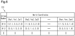
- the first control device 45 stores marker position information D3 in the storage unit 47 in step S5.
- the first control device 45 stores the marker position information D3 in the RAM, which temporarily holds information.
- the marker position information D3 is information in which the world coordinates of target sections of the markers M are associated with the unique numbers of the markers M.
- the target section of each marker M is a feature point generated by the marker M.
- the pixels of the disparity image correspond to the pixels of the reference image. Therefore, the feature point generated by the marker M correspond to pixels that represent the target section of the marker in the reference image.
- the world coordinates of the target section are the world coordinates of a part of the marker M.
- step S2 the four corners of the marker M in the reference image are detected. Since the disparity image is obtained by associating a disparity with the reference image, the first control device 45 can determine whether the coordinates (xp, yp) of the feature point are included in the range surrounded by the four corners of the marker M. The first control device 45 sets the world coordinates obtained from feature points included in the range surrounded by the four corners of the marker M as the world coordinates of the target section. Then, the first control device 45 associates the unique number read in step S2 with the world coordinates of the target section corresponding to the unique number. Multiple feature points are obtained from the marker M. Accordingly, the first control device 45 associates multiple sets of world coordinates of the target section with each of the unique numbers.
- step S6 the first control device 45 performs extraction of an object by clustering the feature points, as shown in Fig. 5 .
- the first control device 45 regards, as a single point cloud, a set of feature points presumed to represent the same object among feature points representing a portion of the object. Then, the first control device 45 extracts the single point cloud as one object. Clustering can be performed using various methods.
- step S7 the first control device 45 derives the world coordinates of the object.
- the world coordinates of the object can be derived from the world coordinates of the feature points included in the point cloud.
- a case of deriving the world coordinates of a marker M will now be described.
- the first control device 45 derives the world coordinates of a marker M from the world coordinates of the target section.
- the first control device 45 may derive the world coordinates of a marker M from the world coordinates of the four corners of the marker M.
- the first control device 45 may set the world coordinates of the marker M to average values of the world coordinates of the four corners of the marker M.
- the world coordinates of the marker M correspond to the world coordinates of the center position of the four corners of the marker M.
- the first control device 45 may set the world coordinates of the marker M to average values of the world coordinates of all the target sections.
- the first control device 45 may derive the world coordinates of the marker M by using simple averages, or may derive the world coordinates of the marker M by using weighted averages in correspondence with to the position.
- the first control device 45 may derive the world coordinates of the marker M from the distribution of the world coordinates of the target section.
- the world coordinates of the marker M represent the relative position of the mobile unit 10 with respect to the marker M.
- the world coordinates of the marker M are an example of the positional relationship between the mobile unit 10 and the marker M based on the marker M.
- step S8 the first control device 45 estimates the self-location of the mobile unit 10.
- the self-location is represented by the coordinates of the mobile unit 10 in the map coordinate system.
- the self-location is the position of the mobile unit 10 in the movement environment A1.
- the first control device 45 detects a marker M1 as shown in Fig. 1
- the first control device 45 reads the unique number from the marker M1. From the marker information D2 and the unique number of the marker M1, the first control device 45 obtains a distance d11 between the origin O and the marker M1 in the map coordinate system, that is, the coordinates of the marker M1 in the map coordinate system.
- the world coordinates represent a relative distance d12 between the marker M1 and the mobile unit 10. In this manner, the first control device 45 recognizes the positional relationship between the origin O of the map coordinate system and the marker M1, and also recognizes the positional relationship between the marker M1 and the mobile unit 10.
- the first control device 45 may estimate the self-location of the mobile unit 10 using the coordinates of the marker M1 in the map coordinate system and the world coordinates of the marker M1.
- the first control device 45 may estimate the self-location of the mobile unit 10 by adding the coordinates of the marker M1 in the map coordinate system and the world coordinates of the marker M1.
- step S9 the second control device 51 executes a control of the mobile unit 10 in accordance with the self-location of the mobile unit 10 as shown in Fig. 5 .
- the second control device 51 determines whether the mobile unit 10 is located in a restricted areas A11.
- the self-location is included in a restricted areas A11 defined by the restricted area information D4
- the second control device 51 determines that the mobile unit 10 is located in the restricted area A11.
- the second control device 51 performs a control in accordance with the restricted area A11.
- the second control device 51 controls the mobile unit 10 so as not to exceed the maximum speed set in the restricted area A11.
- the second control device 51 determines that the mobile unit 10 is located in a restricted area A11. Then, the second control device 51 recognizes the maximum speed set for the restricted area A11 from the restricted area information D4. The second control device 51 controls the mobile unit 10 such that the moving speed of the mobile unit 10 does not exceed the maximum speed.
- the second control device 51 recognizes the maximum lift height set for the restricted area A11 from the restricted area information D4. The second control device 51 controls the mobile unit 10 such that the lift height does not exceed the maximum lift height.
- the first control device 45 may detect a marker M from the comparison image. Since the positional relationship between the first camera 43 and the second camera 44 is constant, the pixel displacement between the comparison image and the reference image, in which the same portion as the comparison image appears, can be obtained in advance. The first control device 45 detects four corners of the marker M in the comparison image. The first control device 45 calculates the positions of the four corners of the marker M in the reference image from the four corners of the marker M in the comparison image. Accordingly, the first control device 45 can perform the processing after step S3 even when the marker M is detected from the comparison image.
- the first control device 45 may detect the marker M from the comparison image. In this case, even when the marker M cannot be detected from the reference image, detection of the marker M from the comparison image allows the information associated with the marker M to be read, and the world coordinates of the marker M to be derived.
- the position of the mobile unit 10 in the movement environment A1 may be a relative position of the mobile unit 10 with respect to a marker M.
- information indicating a restricted area A11 may be associated with the marker M.
- a range of the restricted area A11 with reference to the marker M may be associated with the marker M.
- the range of the restricted area A11 with reference to the marker M may be, for example, a circular range centered on the marker M.
- the second control device 51 determines whether the mobile unit 10 is located in the restricted area A11 from the positional relationship between the mobile unit 10 and the marker M and the information indicating the restricted area A11 read from the marker M. When the mobile unit 10 is located in the restricted area A11, the second control device 51 performs a control such that the moving speed of the mobile unit 10 does not exceed the maximum speed read from the marker M.
- the positional relationship between the mobile unit 10 and a marker M based on the marker M may be a relative distance between the mobile unit 10 and the marker M and a relative angle of the mobile unit 10 with respect to the marker M.
- the map coordinates of the marker M may be associated with the marker M.
- the map coordinates of the marker M may be associated with the marker M as information that defines the absolute position of the marker M in the movement environment A1.
- a unique number corresponding to the map coordinates of each marker M may be associated with the marker M as the information defining the absolute position of the marker M in the movement environment A1.
- the second control device 51 may limit the moving speed of the mobile unit 10 when an object exists within a prescribed range from the mobile unit 10. Whether an object exists within the prescribed range can be determined from the world coordinates of the object. In this case, the prescribed range may be associated with each restricted area A11. The size of the prescribed range may be changed in accordance with each restricted area A11. The second control device 51 sets a prescribed range corresponding to the restricted area A11 in which the mobile unit 10 is located.
- step S1 to step S9 may be executed by the first control device 45. All of the processes of step S1 to step S9 may be executed by the second control device 51. A part of the processes of step S1 to step S9 may be executed by the first control device 45, and the remainder may be executed by the second control device 51. In other words, the processes of steps S1 to S9 can be allocated to the first control device 45 and the second control device 51 in any way.
- the control unit may be a single device.
- the mobile unit 10 may include a communication device. In this case, the mobile unit 10 may be able to communicate with external devices using the communication device. At least one of the map data D1, the marker information D2, and the restricted area information D4 may be updatable by an external device.
- the expression “at least one” as used herein means “one or more” of desired options. As an example, the expression “at least one” as used herein means “only one option” or “both of two options” if the number of options is two. As another example, the expression “at least one” used herein means “only one option” or “a combination of any two or more options” if the number of options is three or more.
Landscapes
- Engineering & Computer Science (AREA)
- Physics & Mathematics (AREA)
- General Physics & Mathematics (AREA)
- Aviation & Aerospace Engineering (AREA)
- Radar, Positioning & Navigation (AREA)
- Remote Sensing (AREA)
- Automation & Control Theory (AREA)
- Theoretical Computer Science (AREA)
- Computer Vision & Pattern Recognition (AREA)
- Multimedia (AREA)
- Transportation (AREA)
- Structural Engineering (AREA)
- Civil Engineering (AREA)
- Life Sciences & Earth Sciences (AREA)
- Geology (AREA)
- Mechanical Engineering (AREA)
- Control Of Position, Course, Altitude, Or Attitude Of Moving Bodies (AREA)
- Image Processing (AREA)
Abstract
Description
- The present disclosure relates to a mobile unit control system.
- A portable device disclosed in
Japanese Laid-Open Patent Publication No. 2020-80147 - In some cases, the positional relationship between a mobile unit and a marker is derived by an image capturing device and a control unit provided in the mobile unit. When an imaging device is installed on a mobile unit, a marker in image data may be distorted due to at least one of the following causes: movement of the mobile unit, vibration applied to the image capturing device from the mobile unit, and constraints on the installation position of the image capturing device. When the marker is distorted, the control unit may not be able to accurately recognize the positional relationship between the mobile unit and the marker. When the positional relationship between the mobile unit and the marker cannot be accurately recognized, the control unit may not be able to appropriately control the mobile unit. For example, when estimating the self-location of the mobile unit using a marker, the control unit acquires image data by capturing images of the marker with the image capturing device. The marker is associated with the absolute position of the marker. The control unit acquires the absolute position of the marker by reading the marker. The control unit calculates a relative position of the mobile unit with respect to the marker from the image data. The control unit estimates the self-location of the mobile unit from the absolute position of the marker and the relative position of the mobile unit with respect to the marker. When the relative position of the mobile unit with respect to the marker cannot be recognized with high accuracy, the estimation accuracy of the self-location decreases.
- This Summary is provided to introduce a selection of concepts in a simplified form that are further described below in the Detailed Description. This Summary is not intended to identify key features or essential features of the claimed subject matter, nor is it intended to be used as an aid in determining the scope of the claimed subject matter.
- In one general aspect, a mobile unit control system includes an image capturing device and a control unit. The image capturing device is attached to a mobile unit and is configured to capture images of a marker disposed in a movement environment of the mobile unit. The image capturing device is a stereo camera unit. The control unit is configured to acquire image data from the image capturing device, detect the marker from the image data, estimate a position of the mobile unit in the movement environment from a positional relationship between the mobile unit and the marker based on the marker, and execute a control based on the estimated position.
- Other features and aspects will be apparent from the following detailed description, the drawings, and the claims.
-
-
Fig. 1 is a schematic diagram showing a movement environment. -
Fig. 2 is a perspective view of a mobile unit moving in the movement environment shown inFig. 1 . -
Fig. 3 is a schematic diagram of the mobile unit shown inFig. 2 . -
Fig. 4 is a diagram illustrating an example of restricted area information. -
Fig. 5 is a flowchart showing a control executed by a mobile unit control system ofFig. 3 . -
Fig. 6 is a diagram illustrating an example of marker position information. - Throughout the drawings and the detailed description, the same reference numerals refer to the same elements. The drawings may not be to scale, and the relative size, proportions, and depiction of elements in the drawings may be exaggerated for clarity, illustration, and convenience.
- This description provides a comprehensive understanding of the methods, apparatuses, and/or systems described. Modifications and equivalents of the methods, apparatuses, and/or systems described are apparent to one of ordinary skill in the art. Sequences of operations are exemplary, and may be changed as apparent to one of ordinary skill in the art, except for operations necessarily occurring in a certain order. Descriptions of functions and constructions that are well known to one of ordinary skill in the art may be omitted.
- Exemplary embodiments may have different forms, and are not limited to the examples described. However, the examples described are thorough and complete, and convey the full scope of the disclosure to one of ordinary skill in the art.
- In this specification, "at least one of A and B" should be understood to mean "only A, only B, or both A and B."
- A mobile unit control system according to one embodiment will now be described.
- As shown in
Fig. 1 , amobile unit 10 moves in a predetermined movement environment A1. The movement environment A1 is, for example, a factory, a distribution warehouse, a maritime port, a commercial facility, or a public facility. The movement environmentA1 is provided with at least one marker M. In the present embodiment, multiple markers M are provided. The markers M are each provided on, for example, a structure that exists in the movement environment A1. The positions of such structures are unlikely to be moved. The markers M are provided on, for example, a wall, a floor, or a column. Each marker M is associated with unique information. In the present embodiment, a unique number is associated with each marker M as unique information. The markers M are, for example, augmented reality (AR) markers, QR codes®, or barcodes. - The
mobile unit 10 is, for example, a vehicle or a flying object. Vehicles include industrial vehicles and passenger cars. Industrial vehicles include, for example, forklifts and towing tractors. As an example, a case in which themobile unit 10 is a forklift will be described. - As shown in
Fig. 2 , themobile unit 10 includes avehicle body 11, two drivenwheels 12, two steeredwheels 14, and amaterial handling device 20. - The
material handling device 20 includes amast 21. Themast 21 is provided in a front of thevehicle body 11. Thematerial handling device 20 includes twoforks 22. Theforks 22 are lifted and lowered along themast 21. Thematerial handling device 20 includeslift cylinders 23. Thelift cylinders 23 are hydraulic cylinders. Thelift cylinders 23 are extended or retracted to lift or lower theforks 22. - As shown in
Fig. 3 , themobile unit 10 includespropulsion motors 31. Themobile unit 10 moves by rotation of the drivenwheels 12, which are driven by thepropulsion motors 31. Thepropulsion motors 31 are respectively provided for the drivenwheels 12. - The
mobile unit 10 includespropulsion control devices 32. Thepropulsion control devices 32 are motor drivers that control the rotation speeds of therespective propulsion motors 31. Thepropulsion control devices 32 are respectively provided for thepropulsion motors 31. - The
mobile unit 10 includesrotation speed sensors 33. Therotation speed sensors 33 are respectively provided for thepropulsion motors 31. Therotation speed sensors 33 each detect a rotation speed of thecorresponding propulsion motor 31. Therotation speed sensors 33 are, for example, rotary encoders. Eachrotation speed sensor 33 outputs an electric signal corresponding to the rotation speed of the associatedpropulsion motor 31 to the associatedpropulsion control device 32. Eachpropulsion control device 32 acquires the rotation speed of thecorresponding propulsion motor 31 from the electric signal of therotation speed sensor 33. - The
mobile unit 10 includes ahydraulic mechanism 34. Thehydraulic mechanism 34 controls supply and discharge of hydraulic oil to and from hydraulic devices. The hydraulic devices include thelift cylinders 23. Thehydraulic mechanism 34 includes a pump that discharges hydraulic oil and a control valve that controls supply and discharge of hydraulic oil to and from hydraulic devices. - The
mobile unit 10 includes alift sensor 35. Thelift sensor 35 detects the lift height of theforks 22. The lift height of thefork 22 is the height from the road surface to theforks 22. - The
mobile unit 10 includes a mobileunit control system 40. The mobileunit control system 40 controls themobile unit 10. - The mobile
unit control system 40 includes acamera unit 41. - The
camera unit 41 includes animage capturing device 42. Theimage capturing device 42 is a stereo camera unit. Theimage capturing device 42 includes a first camera 43 and asecond camera 44. Eachcamera 43, 44 uses, for example, an image sensor. The image sensor is, for example, a CCD image sensor or a CMOS image sensor. The first camera 43 and thesecond camera 44 are disposed apart from each other. The first camera 43 and thesecond camera 44 are disposed such that their optical axes are parallel to each other. Theimage capturing device 42 captures images with each of the first camera 43 and thesecond camera 44. - The
image capturing device 42 is attached to themobile unit 10. Theimage capturing device 42 is disposed so as to capture images of the surroundings of themobile unit 10. Specifically, theimage capturing device 42 is disposed so as to capture images of the markers M disposed in the movement environment A1. Theimage capturing device 42 of the present embodiment is disposed so as to capture images the area behind themobile unit 10. - The
camera unit 41 includes afirst control device 45. Thefirst control device 45 includes aprocessor 46 and astorage unit 47. Theprocessor 46 is, for example, a central processing unit (CPU), a graphics processing unit (GPU), or a digital signal processor (DSP). Thestorage unit 47 includes a random-access memory (RAM) and a read-only memory (ROM). Thestorage unit 47 stores programs for operating themobile unit 10. Thestorage unit 47 stores program codes or commands configured to cause theprocessor 46 to execute processes. Thestorage unit 47, which is a computerreadable medium, includes any type of medium that is accessible by a general-purpose computer or a dedicated computer. Thefirst control device 45 may include a hardware circuit such as an application specific integrated circuit (ASIC) and a field programmable gate array (FPGA). Thefirst control device 45, which is processing circuitry, may include one or more processors that operate according to a computer program, one or more hardware circuits such as an ASIC and an FPGA, or a combination thereof. - The
storage unit 47 stores map data D1. If the mobileunit control system 40 includes an auxiliary storage device, the map data D1 may be stored in the auxiliary storage device. The auxiliary storage device is, for example, a hard disk drive or a solid state drive. - The map data D1 represents the movement environment A1 with coordinates in a map coordinate system. Specifically, the map data D1 represents structures included in the movement environmentA1 with coordinates in the map coordinate system.
- As shown in
Fig. 1 , the map coordinate system is an absolute coordinate system in which the position of the origin O is fixed. The map coordinate system may represent at least positions in the horizontal direction. The map coordinate system may be a two-dimensional coordinate system that represents coordinates in the horizontal direction with an X-axis and a Y-axis orthogonal to each other. The map coordinate system may be a three-dimensional coordinate system that represents coordinates in the horizontal direction with an X-axis and a Y-axis orthogonal to each other, and represents coordinates in the vertical direction with a Z-axis, which is orthogonal to the X-axis and the Y-axis. The map data D1 is created by using, for example, simultaneous localization and mapping (SLAM). The map data D1 is, for example, a point cloud map or an occupancy grid map. Hereinafter, coordinates in the map coordinate system are referred to as map coordinates in some cases. The map coordinates represent absolute positions in the movement environment A1. - As shown in
Fig. 3 , thestorage unit 47 stores marker information D2. The marker information D2 represents the markers M with map coordinates. For example, the marker information D2 may be data that represents the positions of the unique numbers associated with the markers M with map coordinates. Thus, the markers M define the absolute positions of the markers M in the movement environment A1. Thefirst control device 45 can recognize the map coordinates of the markers M by reading the markers M. - The mobile
unit control system 40 includes asecond control device 51, which is processing circuitry. Thesecond control device 51 has, for example, a hardware configuration similar to that of thefirst control device 45. Thesecond control device 51 includes, for example, aprocessor 52 and astorage unit 53. Thefirst control device 45 and thesecond control device 51 are examples of control units. Thefirst control device 45 and thesecond control device 51 are configured to acquire information from each other. - The
second control device 51 performs, for example, a control related to operation of themobile unit 10. For example, thesecond control device 51 outputs a target rotation speed command to thepropulsion control devices 32. The target rotation speed command is a command for instructing a target rotation speed of thepropulsion motors 31. Eachpropulsion control device 32 recognizes the rotation speed of thepropulsion motor 31 by acquiring a detection result of therotation speed sensor 33. Eachpropulsion control device 32 controls thepropulsion motors 31 so that the target rotation speed instructed by the target rotation speed command agrees with the rotation speed of thepropulsion motor 31. Thesecond control device 51 may be configured to lift and lower theforks 22 by controlling thehydraulic mechanism 34. - The
second control device 51 may perform a control to limit the moving speed of themobile unit 10. For example, thesecond control device 51 sets a maximum speed for the moving speed of themobile unit 10. Thesecond control device 51 outputs a target rotation speed command to thepropulsion control devices 32 so that the moving speed of themobile unit 10 does not exceed the set maximum speed. This limits the moving speed of themobile unit 10. - As shown in
Fig. 4 , thestorage unit 53 may store restricted area information D4. The restricted area information D4 is related to restricted areas established in the movement environment A1. As shown inFig. 1 , the movement environment A1 includes at least one restricted area A11. In the present embodiment, multiple restricted areas A11 are established. The restricted areas A11 are defined by map coordinates. For example, when the restricted areas A11 each have a quadrangular shape, each restricted area A11 may be defined by map coordinates of the four corners of the restricted area A11. - The restricted areas A11 are areas in which a restriction is imposed on operation of the
mobile unit 10. As an example, the maximum speed of themobile unit 10 is set in the restricted areas A11. The set maximum speed may be different for each restricted area A11. For example, the movement environment A1 includes an area where a person needs to perform work and an area where themobile unit 10 performs material handling work. In this case, the maximum speed may be set for each restricted area A11 such that the maximum speed is set lower in an area where a person needs to perform work than in an area where themobile unit 10 performs material handling work. - The restricted areas A11 may be areas where the lift height is limited in addition to or instead of the limiting of the maximum speed of the
mobile unit 10. In this case, the maximum lift height is set in the restricted areas A11. Thesecond control device 51 performs a control such that the lift height does not exceed the maximum lift height while recognizing the lift height using thelift sensor 35. - A control executed by the mobile
unit control system 40 will now be described. The mobileunit control system 40 estimates its self-location using the markers M. Then, the mobileunit control system 40 performs a control in accordance with the self-location. The details will be illustrated below. - As shown in
Fig. 5 , in step S1, thefirst control device 45 acquires image data from theimage capturing device 42. The image data includes a reference image and a comparison image. The reference image is captured by the first camera 43. The comparison image is captured by thesecond camera 44. - Next, in step S2, the
first control device 45 detects a marker M from the image data. Detection of the marker M from the image data can be performed using an existing algorithm. For example, thefirst control device 45 detects a marker M using a known open-source software such as ARToolkit. Thefirst control device 45 detects, for example, four corners of the marker M. Then, thefirst control device 45 reads the information associated with the marker M from the region surrounded by the four corners of the marker M. In the present embodiment, thefirst control device 45 detects the marker M from the reference image. - Next, in step S3, the
first control device 45 acquires a disparity image. The disparity image is an image in which a disparity [px] is associated with pixels. The disparity is a difference between positions of the same feature point appearing in the reference image and the comparison image. Thefirst control device 45 compares the reference image with the comparison image. Thefirst control device 45 is capable of calculating the difference between the positions of the same feature point appearing in the reference image and the comparison image. The feature points are, for example, edges of an object. Feature points can be detected, for example, from luminance information. The difference between the positions of the same feature point can be represented by, for example, a pixel displacement. The pixel displacement indicates the number of pixels by which the positions of the same feature point in the reference image and the comparison image are displaced. - The calculation of the disparity will now be described. The
first control device 45 performs a conversion from RGB to YCrCb for each of the reference image and the comparison image. Thefirst control device 45 compares the degrees of similarity between each pixel of the reference image and each pixel of the comparison image. For each pixel of the reference image, thefirst control device 45 extracts the pixel of the comparison image that is most similar to the pixel of the reference image. Then, thefirst control device 45 calculates, as a disparity, the pixel displacement corresponding to the difference in position between the pixel of the reference image and the pixel of the comparison image that is most similar to that pixel of the reference image. Thefirst control device 45 associates the disparity corresponding to each pixel of the reference image with the pixel. As a result, thefirst control device 45 acquires a disparity image. The reference image is thus an image having pixels with which disparities are associated. The comparison image is an image to be compared with the reference image in order to calculate the disparities. - Next, in step S4, the
first control device 45 derives the coordinates of feature points in a world coordinate system. First, thefirst control device 45 derives the coordinates of feature points in a camera coordinate system from the baseline length of theimage capturing device 42, the focal distance of theimage capturing device 42, and the disparity image. The camera coordinate system is a coordinate system having theimage capturing device 42 as the origin. The Z-axis of the camera coordinate system is, for example, an optical axis. The X-axis of the camera coordinate system is an axis orthogonal to the optical axis. The Y-axis of the camera coordinate system is an axis orthogonal to the optical axis and the X-axis. - The position of a feature point in the camera coordinate system can be represented by a Z coordinate Zc, an X coordinate Xc, and a Y coordinate Yc in the camera coordinate system. The Z coordinate Zc, the X coordinate Xc, and the Y coordinate Yc can be derived using the following Expressions (1) to (3), respectively.


- In Expressions (1) to (3), the symbol B represents a baseline length [mm]. The symbol f represents a focal length [mm]. The symbol d represents a disparity [px]. The symbol xp represents any X coordinate in the disparity image. The symbol x' represents the X coordinate of the center point of the disparity image. The symbol yp represents an any Y coordinate in the disparity image. The symbol y' represents the Y coordinate of the center point of the disparity image.
- The
first control device 45 determines xp as the X coordinate of a feature point in the disparity image, determines yp as the Y coordinate of the feature point in the disparity image, and determines d as a disparity associated with the coordinates of the feature point, thereby deriving the coordinates of the feature point in the camera coordinate system. - The world coordinate system is a coordinate system in real space. The X-axis of the world coordinate system is an axis extending in a horizontal direction in a state in which the
mobile unit 10 is positioned on a horizontal plane. Specifically, the X-axis extends in the width direction of themobile unit 10. The Y-axis of the world coordinate system is an axis orthogonal to a horizontal direction; specifically to the X axis. The Z-axis of the world coordinate system is an axis orthogonal to the X-axis and the Y-axis of the world coordinate system. The origin of the world coordinate system, for example, is located at the position where the X and Y coordinates correspond to the location of theimage capturing device 42, and the Z coordinate is at the level of the road surface. The origin of the world coordinate system represents the position of themobile unit 10. The coordinates in the world coordinate system represent a relative position with respect to themobile unit 10. The position of a feature point in the world coordinate system can be represented by an X coordinate Xw, a Y coordinate Yw, and a Z coordinate Zw in the world coordinate system. - The
first control device 45 converts coordinates in the camera coordinate system into coordinates in the world coordinate system using the following Expression (4). Thefirst control device 45 thus obtains the coordinates of the feature point in the world coordinate system.
- The symbol H in Expression (4) represents the installation height [mm] of the
image capturing device 42 in the world coordinate system. The symbol θ represents an angle formed by adding 90° to the angle between the optical axis and the horizontal plane. Coordinates in the world coordinate system are referred to as world coordinates in some cases. - Next, as shown in
Figs. 5 and6 , thefirst control device 45 stores marker position information D3 in thestorage unit 47 in step S5. For example, thefirst control device 45 stores the marker position information D3 in the RAM, which temporarily holds information. - As shown in
Fig. 6 , the marker position information D3 is information in which the world coordinates of target sections of the markers M are associated with the unique numbers of the markers M. The target section of each marker M is a feature point generated by the marker M. The pixels of the disparity image correspond to the pixels of the reference image. Therefore, the feature point generated by the marker M correspond to pixels that represent the target section of the marker in the reference image. The world coordinates of the target section are the world coordinates of a part of the marker M. - In step S2, the four corners of the marker M in the reference image are detected. Since the disparity image is obtained by associating a disparity with the reference image, the
first control device 45 can determine whether the coordinates (xp, yp) of the feature point are included in the range surrounded by the four corners of the marker M. Thefirst control device 45 sets the world coordinates obtained from feature points included in the range surrounded by the four corners of the marker M as the world coordinates of the target section. Then, thefirst control device 45 associates the unique number read in step S2 with the world coordinates of the target section corresponding to the unique number. Multiple feature points are obtained from the marker M. Accordingly, thefirst control device 45 associates multiple sets of world coordinates of the target section with each of the unique numbers. - Next, in step S6, the
first control device 45 performs extraction of an object by clustering the feature points, as shown inFig. 5 . Thefirst control device 45 regards, as a single point cloud, a set of feature points presumed to represent the same object among feature points representing a portion of the object. Then, thefirst control device 45 extracts the single point cloud as one object. Clustering can be performed using various methods. - Next, in step S7, the
first control device 45 derives the world coordinates of the object. The world coordinates of the object can be derived from the world coordinates of the feature points included in the point cloud. As an example, a case of deriving the world coordinates of a marker M will now be described. - The
first control device 45 derives the world coordinates of a marker M from the world coordinates of the target section. Thefirst control device 45 may derive the world coordinates of a marker M from the world coordinates of the four corners of the marker M. For example, thefirst control device 45 may set the world coordinates of the marker M to average values of the world coordinates of the four corners of the marker M. In this case, the world coordinates of the marker M correspond to the world coordinates of the center position of the four corners of the marker M. Thefirst control device 45 may set the world coordinates of the marker M to average values of the world coordinates of all the target sections. In this case, thefirst control device 45 may derive the world coordinates of the marker M by using simple averages, or may derive the world coordinates of the marker M by using weighted averages in correspondence with to the position. Thefirst control device 45 may derive the world coordinates of the marker M from the distribution of the world coordinates of the target section. The world coordinates of the marker M represent the relative position of themobile unit 10 with respect to the marker M. The world coordinates of the marker M are an example of the positional relationship between themobile unit 10 and the marker M based on the marker M. - Next, in step S8, the
first control device 45 estimates the self-location of themobile unit 10. The self-location is represented by the coordinates of themobile unit 10 in the map coordinate system. The self-location is the position of themobile unit 10 in the movement environment A1. - As an example, a case in which the
first control device 45 detects a marker M1 as shown inFig. 1 will be described. Thefirst control device 45 reads the unique number from the marker M1. From the marker information D2 and the unique number of the marker M1, thefirst control device 45 obtains a distance d11 between the origin O and the marker M1 in the map coordinate system, that is, the coordinates of the marker M1 in the map coordinate system. The world coordinates represent a relative distance d12 between the marker M1 and themobile unit 10. In this manner, thefirst control device 45 recognizes the positional relationship between the origin O of the map coordinate system and the marker M1, and also recognizes the positional relationship between the marker M1 and themobile unit 10. This allows thefirst control device 45 to estimate the self-location of themobile unit 10 using the coordinates of the marker M1 in the map coordinate system and the world coordinates of the marker M1. For example, thefirst control device 45 may estimate the self-location of themobile unit 10 by adding the coordinates of the marker M1 in the map coordinate system and the world coordinates of the marker M1. - Next, in step S9, the
second control device 51 executes a control of themobile unit 10 in accordance with the self-location of themobile unit 10 as shown inFig. 5 . When acquiring the self-location of themobile unit 10 from thefirst control device 45, thesecond control device 51 determines whether themobile unit 10 is located in a restricted areas A11. When the self-location is included in a restricted areas A11 defined by the restricted area information D4, thesecond control device 51 determines that themobile unit 10 is located in the restricted area A11. When themobile unit 10 is located in a restricted area A11, thesecond control device 51 performs a control in accordance with the restricted area A11. When the maximum speed is set in the restricted area A11, thesecond control device 51 controls themobile unit 10 so as not to exceed the maximum speed set in the restricted area A11. In the example shown inFig. 1 , thesecond control device 51 determines that themobile unit 10 is located in a restricted area A11. Then, thesecond control device 51 recognizes the maximum speed set for the restricted area A11 from the restricted area information D4. Thesecond control device 51 controls themobile unit 10 such that the moving speed of themobile unit 10 does not exceed the maximum speed. When the limitation of the lift height is imposed on the restricted area A11, thesecond control device 51 recognizes the maximum lift height set for the restricted area A11 from the restricted area information D4. Thesecond control device 51 controls themobile unit 10 such that the lift height does not exceed the maximum lift height. -
- (1) The
first control device 45 detects a marker M from the image data captured by theimage capturing device 42. Theimage capturing device 42 includes a stereo camera unit including two cameras. Therefore, based on the principle of triangulation, the positional relationship between themobile unit 10 and marker M is accurately estimated. - (2) Each marker M defines map coordinates that correspond to the absolute position of the marker M in the movement environment A1. The
first control device 45 recognizes the map coordinates of the marker M by reading the marker M. Thefirst control device 45 estimates the self-location of themobile unit 10 from the map coordinates of the marker M and the relative position of themobile unit 10 with respect to the marker M. The estimated self-location of themobile unit 10 corresponds to the absolute position of themobile unit 10 in the movement environment A1. Thus, thesecond control device 51 performs a control in accordance with the self-location of themobile unit 10. For example, as described in the embodiment, thesecond control device 51 may determine whether themobile unit 10 is located in a restricted area A11 from the self-location of themobile unit 10. Thesecond control device 51 may generate a route for autonomous driving of themobile unit 10 based on the self-location of themobile unit 10. - (3) The
first control device 45 derives the world coordinates of a marker M from the pixels that represent the target section of the marker M. This allows the positional relationship between themobile unit 10 and the marker M to be accurately estimated. - (4) The
first control device 45 detects a marker M from the reference image. Thefirst control device 45 acquires a disparity image by associating a disparity with pixels of the reference image. Since the pixels of the reference image and the pixels of the disparity image correspond to each other, thefirst control device 45 recognizes the position of the marker M in the disparity image by detecting the marker M from the reference image. - The above-described embodiment may be modified as follows. The above-described embodiment and the following modifications can be combined as long as the combined modifications remain technically consistent with each other.
- The
first control device 45 may detect a marker M from the comparison image. Since the positional relationship between the first camera 43 and thesecond camera 44 is constant, the pixel displacement between the comparison image and the reference image, in which the same portion as the comparison image appears, can be obtained in advance. Thefirst control device 45 detects four corners of the marker M in the comparison image. Thefirst control device 45 calculates the positions of the four corners of the marker M in the reference image from the four corners of the marker M in the comparison image. Accordingly, thefirst control device 45 can perform the processing after step S3 even when the marker M is detected from the comparison image. - When a marker M cannot be detected from the reference image, the
first control device 45 may detect the marker M from the comparison image. In this case, even when the marker M cannot be detected from the reference image, detection of the marker M from the comparison image allows the information associated with the marker M to be read, and the world coordinates of the marker M to be derived. - The position of the
mobile unit 10 in the movement environment A1 may be a relative position of themobile unit 10 with respect to a marker M. In this case, information indicating a restricted area A11 may be associated with the marker M. For example, a range of the restricted area A11 with reference to the marker M may be associated with the marker M. The range of the restricted area A11 with reference to the marker M may be, for example, a circular range centered on the marker M. In this case, thesecond control device 51 determines whether themobile unit 10 is located in the restricted area A11 from the positional relationship between themobile unit 10 and the marker M and the information indicating the restricted area A11 read from the marker M. When themobile unit 10 is located in the restricted area A11, thesecond control device 51 performs a control such that the moving speed of themobile unit 10 does not exceed the maximum speed read from the marker M. - The positional relationship between the
mobile unit 10 and a marker M based on the marker M may be a relative distance between themobile unit 10 and the marker M and a relative angle of themobile unit 10 with respect to the marker M. - The map coordinates of the marker M may be associated with the marker M. Specifically, the map coordinates of the marker M may be associated with the marker M as information that defines the absolute position of the marker M in the movement environment A1. As in the above-described embodiment, a unique number corresponding to the map coordinates of each marker M may be associated with the marker M as the information defining the absolute position of the marker M in the movement environment A1.
- The
second control device 51 may limit the moving speed of themobile unit 10 when an object exists within a prescribed range from themobile unit 10. Whether an object exists within the prescribed range can be determined from the world coordinates of the object. In this case, the prescribed range may be associated with each restricted area A11. The size of the prescribed range may be changed in accordance with each restricted area A11. Thesecond control device 51 sets a prescribed range corresponding to the restricted area A11 in which themobile unit 10 is located. - All of the processes of step S1 to step S9 may be executed by the
first control device 45. All of the processes of step S1 to step S9 may be executed by thesecond control device 51. A part of the processes of step S1 to step S9 may be executed by thefirst control device 45, and the remainder may be executed by thesecond control device 51. In other words, the processes of steps S1 to S9 can be allocated to thefirst control device 45 and thesecond control device 51 in any way. - The control unit may be a single device.
- The
mobile unit 10 may include a communication device. In this case, themobile unit 10 may be able to communicate with external devices using the communication device. At least one of the map data D1, the marker information D2, and the restricted area information D4 may be updatable by an external device. The expression "at least one" as used herein means "one or more" of desired options. As an example, the expression "at least one" as used herein means "only one option" or "both of two options" if the number of options is two. As another example, the expression "at least one" used herein means "only one option" or "a combination of any two or more options" if the number of options is three or more. - Various changes in form and details may be made to the examples above without departing from the spirit and scope of the claims and their equivalents. The examples are for the sake of description only, and not for purposes of limitation. Descriptions of features in each example are to be considered as being applicable to similar features or aspects in other examples. Suitable results may be achieved if sequences are performed in a different order, and/or if components in a described system, architecture, device, or circuit are combined differently, and/or replaced or supplemented by other components or their equivalents. The scope of the disclosure is not defined by the detailed description, but by the claims and their equivalents. All variations within the scope of the claims and their equivalents are included in the disclosure.
Claims (5)
- A mobile unit control system (40), comprising:an image capturing device (42) attached to a mobile unit (10), the image capturing device (42) being configured to capture images of a marker (M) disposed in a movement environment of the mobile unit (10); anda control unit (45, 51), whereinthe image capturing device (42) is a stereo camera unit, andthe control unit (45, 51) is configured toacquire image data from the image capturing device (42),detect the marker (M) from the image data,estimate a position of the mobile unit (10) in the movement environment from a positional relationship between the mobile unit (10) and the marker (M) based on the marker (M), andexecute a control based on the estimated position.
- The mobile unit control system (40) according to claim 1, whereinthe marker (M) defines an absolute position of the marker (M) in the movement environment, andthe control unit (45, 51) is configured toacquire the absolute position from the marker (M),acquire a relative position of the mobile unit (10) with respect to the marker (M), andderive an absolute position of the mobile unit (10) in the movement environment from the absolute position of the marker (M) and the acquired relative position of the mobile unit (10).
- The mobile unit control system (40) according to claim 2, further comprising a storage unit (47), whereinthe storage unit (47) is configured to store map data representing the movement environment using coordinates in a map coordinate system, andthe control unit (45, 51) is configured to acquire coordinates in the map coordinate system as the absolute positions of the marker (M) and the mobile unit (10).
- The mobile unit control system (40) according to claim 1, whereinthe stereo camera unit includes:a first camera (43); anda second camera (44),the image data includes:a reference image obtained by the first camera (43); anda comparison image obtained by the second camera (44), andthe control unit (45, 51) is configured toassociate a disparity with pixels of the reference image, andderive a positional relationship between the image capturing device (42) and the marker (M) from the pixels capturing a target section of the marker (M).
- The mobile unit control system (40) according to claim 1, whereinthe stereo camera unit includes:a first camera (43); anda second camera (44),the image data includes:a reference image obtained by the first camera (43); anda comparison image obtained by the second camera (44), andthe control unit (45, 51) is configured todetect the marker (M) from the reference image, andassociate a disparity with pixels of the reference image.
Applications Claiming Priority (1)
| Application Number | Priority Date | Filing Date | Title |
|---|---|---|---|
| JP2023061957A JP2024148638A (en) | 2023-04-06 | 2023-04-06 | Mobile Control System |
Publications (2)
| Publication Number | Publication Date |
|---|---|
| EP4443262A1 true EP4443262A1 (en) | 2024-10-09 |
| EP4443262B1 EP4443262B1 (en) | 2026-04-29 |
Family
ID=90482500
Family Applications (1)
| Application Number | Title | Priority Date | Filing Date |
|---|---|---|---|
| EP24166765.8A Active EP4443262B1 (en) | 2023-04-06 | 2024-03-27 | Mobile unit control system |
Country Status (7)
| Country | Link |
|---|---|
| US (1) | US20240338843A1 (en) |
| EP (1) | EP4443262B1 (en) |
| JP (1) | JP2024148638A (en) |
| KR (1) | KR20240149793A (en) |
| CN (1) | CN118778625A (en) |
| AU (1) | AU2024202082B2 (en) |
| CA (1) | CA3234044A1 (en) |
Citations (4)
| Publication number | Priority date | Publication date | Assignee | Title |
|---|---|---|---|---|
| US20140267703A1 (en) * | 2013-03-15 | 2014-09-18 | Robert M. Taylor | Method and Apparatus of Mapping Landmark Position and Orientation |
| US20180088586A1 (en) * | 2016-09-26 | 2018-03-29 | X Development Llc | Identification Information for Warehouse Navigation |
| JP2020080147A (en) | 2018-11-13 | 2020-05-28 | 株式会社東芝 | Maintenance activity support system and maintenance activity support method |
| JP2022012369A (en) * | 2020-07-01 | 2022-01-17 | 株式会社豊田自動織機 | Industrial vehicle |
Family Cites Families (1)
| Publication number | Priority date | Publication date | Assignee | Title |
|---|---|---|---|---|
| JP2015141580A (en) * | 2014-01-29 | 2015-08-03 | トヨタ自動車株式会社 | Mobile device |
-
2023
- 2023-04-06 JP JP2023061957A patent/JP2024148638A/en active Pending
-
2024
- 2024-03-27 EP EP24166765.8A patent/EP4443262B1/en active Active
- 2024-03-29 KR KR1020240043158A patent/KR20240149793A/en active Pending
- 2024-04-01 US US18/623,381 patent/US20240338843A1/en active Pending
- 2024-04-02 AU AU2024202082A patent/AU2024202082B2/en active Active
- 2024-04-03 CN CN202410399215.9A patent/CN118778625A/en active Pending
- 2024-04-03 CA CA3234044A patent/CA3234044A1/en active Pending
Patent Citations (4)
| Publication number | Priority date | Publication date | Assignee | Title |
|---|---|---|---|---|
| US20140267703A1 (en) * | 2013-03-15 | 2014-09-18 | Robert M. Taylor | Method and Apparatus of Mapping Landmark Position and Orientation |
| US20180088586A1 (en) * | 2016-09-26 | 2018-03-29 | X Development Llc | Identification Information for Warehouse Navigation |
| JP2020080147A (en) | 2018-11-13 | 2020-05-28 | 株式会社東芝 | Maintenance activity support system and maintenance activity support method |
| JP2022012369A (en) * | 2020-07-01 | 2022-01-17 | 株式会社豊田自動織機 | Industrial vehicle |
Also Published As
| Publication number | Publication date |
|---|---|
| JP2024148638A (en) | 2024-10-18 |
| AU2024202082B2 (en) | 2025-11-13 |
| EP4443262B1 (en) | 2026-04-29 |
| CA3234044A1 (en) | 2025-06-18 |
| AU2024202082A1 (en) | 2024-10-24 |
| KR20240149793A (en) | 2024-10-15 |
| US20240338843A1 (en) | 2024-10-10 |
| CN118778625A (en) | 2024-10-15 |
Similar Documents
| Publication | Publication Date | Title |
|---|---|---|
| CN110837814B (en) | Vehicle navigation method, device and computer readable storage medium | |
| EP2144131B1 (en) | Apparatus and method of building map for mobile robot | |
| US10977504B2 (en) | Vehicle-mounted image target objection recognition device | |
| WO2021093240A1 (en) | Method and system for camera-lidar calibration | |
| KR101633620B1 (en) | Feature registration apparatus for image based localization and method the same | |
| JP7482453B2 (en) | Positioning device and mobile object | |
| JP7599136B2 (en) | Positioning device and mobile object | |
| US20110205338A1 (en) | Apparatus for estimating position of mobile robot and method thereof | |
| US20120308114A1 (en) | Voting strategy for visual ego-motion from stereo | |
| CN105934774A (en) | Object detection apparatus, object detection method, and mobile robot | |
| JP7689308B2 (en) | Positioning system | |
| JP2005326944A (en) | Apparatus and method for generating map image by laser measurement | |
| JP7675557B2 (en) | Positioning System | |
| JP2017120551A (en) | Autonomous traveling device | |
| EP3690724B1 (en) | Estimating passenger statuses in 2 dimensional images captured using a fisheye lens | |
| CN111788573B (en) | Sky determination in environment detection for mobile platforms and related systems and methods | |
| CN212669124U (en) | Forklift truck | |
| JP5819257B2 (en) | Moving object position estimation method and moving object | |
| WO2016152755A1 (en) | Object recognition device | |
| WO2020090897A1 (en) | Position detecting device, position detecting system, remote control device, remote control system, position detecting method, and program | |
| JP2001076128A (en) | Obstacle detection apparatus and method | |
| EP4443262B1 (en) | Mobile unit control system | |
| US20250102650A1 (en) | Vehicle sensor calibration method and system | |
| JPH1185981A (en) | Distance measurement origin recognition device for moving objects | |
| KR100784125B1 (en) | Method of Extracting Coordinates of Landmark of Mobile Robot Using Single Camera |
Legal Events
| Date | Code | Title | Description |
|---|---|---|---|
| PUAI | Public reference made under article 153(3) epc to a published international application that has entered the european phase |
Free format text: ORIGINAL CODE: 0009012 |
|
| STAA | Information on the status of an ep patent application or granted ep patent |
Free format text: STATUS: REQUEST FOR EXAMINATION WAS MADE |
|
| 17P | Request for examination filed |
Effective date: 20240327 |
|
| AK | Designated contracting states |
Kind code of ref document: A1 Designated state(s): AL AT BE BG CH CY CZ DE DK EE ES FI FR GB GR HR HU IE IS IT LI LT LU LV MC ME MK MT NL NO PL PT RO RS SE SI SK SM TR |
|
| STAA | Information on the status of an ep patent application or granted ep patent |
Free format text: STATUS: EXAMINATION IS IN PROGRESS |
|
| RIC1 | Information provided on ipc code assigned before grant |
Ipc: G06V 20/56 20220101ALN20250430BHEP Ipc: G06V 10/24 20220101ALN20250430BHEP Ipc: B66F 9/075 20060101ALN20250430BHEP Ipc: G05D 111/63 20240101ALI20250430BHEP Ipc: G06V 20/00 20220101ALI20250430BHEP Ipc: G06T 7/00 20170101ALI20250430BHEP Ipc: G05D 111/10 20240101ALI20250430BHEP Ipc: G05D 109/10 20240101ALI20250430BHEP Ipc: G05D 107/70 20240101ALI20250430BHEP Ipc: G05D 105/28 20240101ALI20250430BHEP Ipc: G05D 1/246 20240101ALI20250430BHEP Ipc: B66F 9/00 20060101ALI20250430BHEP Ipc: G05D 1/244 20240101AFI20250430BHEP |
|
| 17Q | First examination report despatched |
Effective date: 20250509 |
|
| GRAP | Despatch of communication of intention to grant a patent |
Free format text: ORIGINAL CODE: EPIDOSNIGR1 |
|
| STAA | Information on the status of an ep patent application or granted ep patent |
Free format text: STATUS: GRANT OF PATENT IS INTENDED |
|
| RIC1 | Information provided on ipc code assigned before grant |
Ipc: G05D 1/244 20240101AFI20260109BHEP Ipc: B66F 9/00 20060101ALI20260109BHEP Ipc: G05D 1/246 20240101ALI20260109BHEP Ipc: G05D 105/28 20240101ALI20260109BHEP Ipc: G05D 107/70 20240101ALI20260109BHEP Ipc: G05D 109/10 20240101ALI20260109BHEP Ipc: G05D 111/10 20240101ALI20260109BHEP Ipc: G06T 7/00 20170101ALI20260109BHEP Ipc: G06V 20/00 20220101ALI20260109BHEP Ipc: G05D 111/63 20240101ALI20260109BHEP Ipc: B66F 9/075 20060101ALN20260109BHEP Ipc: G06V 10/24 20220101ALN20260109BHEP Ipc: G06V 20/56 20220101ALN20260109BHEP |
|
| INTG | Intention to grant announced |
Effective date: 20260128 |
|
| GRAS | Grant fee paid |
Free format text: ORIGINAL CODE: EPIDOSNIGR3 |
|
| GRAA | (expected) grant |
Free format text: ORIGINAL CODE: 0009210 |
|
| STAA | Information on the status of an ep patent application or granted ep patent |
Free format text: STATUS: THE PATENT HAS BEEN GRANTED |
|
| AK | Designated contracting states |
Kind code of ref document: B1 Designated state(s): AL AT BE BG CH CY CZ DE DK EE ES FI FR GB GR HR HU IE IS IT LI LT LU LV MC ME MK MT NL NO PL PT RO RS SE SI SK SM TR |
|
| REG | Reference to a national code |
Ref country code: CH Ref legal event code: F10 Free format text: ST27 STATUS EVENT CODE: U-0-0-F10-F00 (AS PROVIDED BY THE NATIONAL OFFICE) Effective date: 20260429 Ref country code: GB Ref legal event code: FG4D |