EP4443181A1 - Magnetic sensor and magnetic field measurement device using the same - Google Patents
Magnetic sensor and magnetic field measurement device using the same Download PDFInfo
- Publication number
- EP4443181A1 EP4443181A1 EP24164810.4A EP24164810A EP4443181A1 EP 4443181 A1 EP4443181 A1 EP 4443181A1 EP 24164810 A EP24164810 A EP 24164810A EP 4443181 A1 EP4443181 A1 EP 4443181A1
- Authority
- EP
- European Patent Office
- Prior art keywords
- magnetic field
- coil
- magnetic
- magnetosensitive element
- excitation
- Prior art date
- Legal status (The legal status is an assumption and is not a legal conclusion. Google has not performed a legal analysis and makes no representation as to the accuracy of the status listed.)
- Pending
Links
Images



Classifications
-
- G—PHYSICS
- G01—MEASURING; TESTING
- G01R—MEASURING ELECTRIC VARIABLES; MEASURING MAGNETIC VARIABLES
- G01R33/00—Arrangements or instruments for measuring magnetic variables
- G01R33/12—Measuring magnetic properties of articles or specimens of solids or fluids
- G01R33/1276—Measuring magnetic properties of articles or specimens of solids or fluids of magnetic particles, e.g. imaging of magnetic nanoparticles
-
- G—PHYSICS
- G01—MEASURING; TESTING
- G01R—MEASURING ELECTRIC VARIABLES; MEASURING MAGNETIC VARIABLES
- G01R15/00—Details of measuring arrangements of the types provided for in groups G01R17/00 - G01R29/00, G01R33/00 - G01R33/26 or G01R35/00
- G01R15/14—Adaptations providing voltage or current isolation, e.g. for high-voltage or high-current networks
- G01R15/20—Adaptations providing voltage or current isolation, e.g. for high-voltage or high-current networks using galvano-magnetic devices, e.g. Hall-effect devices, i.e. measuring a magnetic field via the interaction between a current and a magnetic field, e.g. magneto resistive or Hall effect devices
- G01R15/205—Adaptations providing voltage or current isolation, e.g. for high-voltage or high-current networks using galvano-magnetic devices, e.g. Hall-effect devices, i.e. measuring a magnetic field via the interaction between a current and a magnetic field, e.g. magneto resistive or Hall effect devices using magneto-resistance devices, e.g. field plates
-
- G—PHYSICS
- G01—MEASURING; TESTING
- G01R—MEASURING ELECTRIC VARIABLES; MEASURING MAGNETIC VARIABLES
- G01R33/00—Arrangements or instruments for measuring magnetic variables
-
- G—PHYSICS
- G01—MEASURING; TESTING
- G01R—MEASURING ELECTRIC VARIABLES; MEASURING MAGNETIC VARIABLES
- G01R33/00—Arrangements or instruments for measuring magnetic variables
- G01R33/0011—Arrangements or instruments for measuring magnetic variables comprising means, e.g. flux concentrators, flux guides, for guiding or concentrating the magnetic flux, e.g. to the magnetic sensor
-
- G—PHYSICS
- G01—MEASURING; TESTING
- G01R—MEASURING ELECTRIC VARIABLES; MEASURING MAGNETIC VARIABLES
- G01R33/00—Arrangements or instruments for measuring magnetic variables
- G01R33/0017—Means for compensating offset magnetic fields or the magnetic flux to be measured; Means for generating calibration magnetic fields
-
- G—PHYSICS
- G01—MEASURING; TESTING
- G01R—MEASURING ELECTRIC VARIABLES; MEASURING MAGNETIC VARIABLES
- G01R33/00—Arrangements or instruments for measuring magnetic variables
- G01R33/007—Environmental aspects, e.g. temperature variations, radiation, stray fields
- G01R33/0076—Protection, e.g. with housings against stray fields
-
- G—PHYSICS
- G01—MEASURING; TESTING
- G01R—MEASURING ELECTRIC VARIABLES; MEASURING MAGNETIC VARIABLES
- G01R33/00—Arrangements or instruments for measuring magnetic variables
- G01R33/0094—Sensor arrays
-
- G—PHYSICS
- G01—MEASURING; TESTING
- G01R—MEASURING ELECTRIC VARIABLES; MEASURING MAGNETIC VARIABLES
- G01R33/00—Arrangements or instruments for measuring magnetic variables
- G01R33/02—Measuring direction or magnitude of magnetic fields or magnetic flux
- G01R33/025—Compensating stray fields
-
- G—PHYSICS
- G01—MEASURING; TESTING
- G01R—MEASURING ELECTRIC VARIABLES; MEASURING MAGNETIC VARIABLES
- G01R33/00—Arrangements or instruments for measuring magnetic variables
- G01R33/02—Measuring direction or magnitude of magnetic fields or magnetic flux
- G01R33/06—Measuring direction or magnitude of magnetic fields or magnetic flux using galvano-magnetic devices
-
- G—PHYSICS
- G01—MEASURING; TESTING
- G01R—MEASURING ELECTRIC VARIABLES; MEASURING MAGNETIC VARIABLES
- G01R33/00—Arrangements or instruments for measuring magnetic variables
- G01R33/02—Measuring direction or magnitude of magnetic fields or magnetic flux
- G01R33/06—Measuring direction or magnitude of magnetic fields or magnetic flux using galvano-magnetic devices
- G01R33/063—Magneto-impedance sensors; Nanocristallin sensors
-
- G—PHYSICS
- G01—MEASURING; TESTING
- G01R—MEASURING ELECTRIC VARIABLES; MEASURING MAGNETIC VARIABLES
- G01R33/00—Arrangements or instruments for measuring magnetic variables
- G01R33/02—Measuring direction or magnitude of magnetic fields or magnetic flux
- G01R33/06—Measuring direction or magnitude of magnetic fields or magnetic flux using galvano-magnetic devices
- G01R33/09—Magnetoresistive devices
-
- G—PHYSICS
- G01—MEASURING; TESTING
- G01R—MEASURING ELECTRIC VARIABLES; MEASURING MAGNETIC VARIABLES
- G01R33/00—Arrangements or instruments for measuring magnetic variables
- G01R33/02—Measuring direction or magnitude of magnetic fields or magnetic flux
- G01R33/06—Measuring direction or magnitude of magnetic fields or magnetic flux using galvano-magnetic devices
- G01R33/09—Magnetoresistive devices
- G01R33/091—Constructional adaptation of the sensor to specific applications
-
- G—PHYSICS
- G01—MEASURING; TESTING
- G01R—MEASURING ELECTRIC VARIABLES; MEASURING MAGNETIC VARIABLES
- G01R33/00—Arrangements or instruments for measuring magnetic variables
- G01R33/02—Measuring direction or magnitude of magnetic fields or magnetic flux
- G01R33/06—Measuring direction or magnitude of magnetic fields or magnetic flux using galvano-magnetic devices
- G01R33/09—Magnetoresistive devices
- G01R33/093—Magnetoresistive devices using multilayer structures, e.g. giant magnetoresistance sensors
-
- G—PHYSICS
- G01—MEASURING; TESTING
- G01R—MEASURING ELECTRIC VARIABLES; MEASURING MAGNETIC VARIABLES
- G01R33/00—Arrangements or instruments for measuring magnetic variables
- G01R33/02—Measuring direction or magnitude of magnetic fields or magnetic flux
- G01R33/06—Measuring direction or magnitude of magnetic fields or magnetic flux using galvano-magnetic devices
- G01R33/09—Magnetoresistive devices
- G01R33/095—Magnetoresistive devices extraordinary magnetoresistance sensors
-
- G—PHYSICS
- G01—MEASURING; TESTING
- G01R—MEASURING ELECTRIC VARIABLES; MEASURING MAGNETIC VARIABLES
- G01R33/00—Arrangements or instruments for measuring magnetic variables
- G01R33/12—Measuring magnetic properties of articles or specimens of solids or fluids
-
- G—PHYSICS
- G01—MEASURING; TESTING
- G01R—MEASURING ELECTRIC VARIABLES; MEASURING MAGNETIC VARIABLES
- G01R33/00—Arrangements or instruments for measuring magnetic variables
- G01R33/02—Measuring direction or magnitude of magnetic fields or magnetic flux
- G01R33/06—Measuring direction or magnitude of magnetic fields or magnetic flux using galvano-magnetic devices
- G01R33/07—Hall effect devices
- G01R33/072—Constructional adaptation of the sensor to specific applications
Definitions
- the present disclosure relates to a magnetic sensor and a magnetic field measurement device using the magnetic sensor and, more particularly, to a magnetic sensor capable of detecting a feeble magnetic field and a magnetic field measurement device using such a magnetic sensor.
- the magnetic sensor disclosed in International Publication WO 2021/100252 has difficulty in ensuring a sufficient S/N ratio due to degradation of its detection sensitivity when distant from a measurement target increases.
- the present disclosure describes an improved magnetic sensor capable of detecting a feeble magnetic field and a magnetic field measurement device using such a magnetic sensor.
- a magnetic sensor includes: a magnetosensitive element; a cancellation coil cancelling a component on the magnetosensitive element of an AC excitation magnetic field applied to a measurement target including a magnetic material; a receiving coil receiving a primary magnetic field generated from the magnetic material; and a transmitting coil connected to the receiving coil and applying a secondary magnetic field to the magnetosensitive element based on a detection current supplied from the receiving coil.
- a magnetic field measurement device includes the above-described magnetic sensor and an excitation coil that applies the AC excitation magnetic field to the magnetic material.
- FIG. 1 is a schematic view for explaining the configuration of a magnetic field measurement device 10 according to an embodiment of the technology disclosed herein.
- the magnetic field measurement device 10 is a device for detecting a magnetic material P positioned within the measurement area A set in a measurement target and includes an excitation coil 20 and a magnetic sensor 100 as illustrated in FIG. 1 .
- the excitation coil 20 applies an AC excitation magnetic field to the measurement target including the magnetic material P to magnetically or physically vibrate the magnetic material P at a predetermined frequency.
- the vibration of the magnetic material P appears as a change in a magnetic field generated from the magnetic material P.
- the magnetic sensor 100 detects a change in the magnetic field.
- the magnetic material P may be nanosized magnetic nanoparticles. Using the magnetic nanoparticles as the magnetic material P allows a human body to be measured.
- the magnetic field measurement device 10 can also detect a metal member positioned within the measurement area A. When a metal member is present within the measurement area A, an eddy current is generated in the metal member by a magnetic field from the excitation coil 20. The eddy current generates a new magnetic field, which is detected by the magnetic sensor 100.
- the magnetic sensor 100 includes a magnetosensitive element 101, a magnetic field concentrator 102 for focusing a magnetic field on the magnetosensitive element 101, a compensation coil 111 wound around the magnetic field concentrator 102, a cancellation coil 112, a transmitting coil 113, and a receiving coil 120.
- magnetoresistive effect elements such as a TMR (Tunnel Magneto-Resistive effect) element, a GMR (Giant Magneto-Resistive effect) element, and an AMR (Anisotropic Magneto-Resistive effect) element; a hall element; and an MI (Magnetic Impedance) element may be used.
- the sensitivity direction of the magnetosensitive element 101 is the X-direction, and the magnetic field concentrator 102 acts to collect a magnetic field in the X-direction.
- the magnetic field concentrator 102 need not necessarily be used in the present invention, it is preferably used in order to enhance magnetic flux density to be applied to the magnetosensitive element 101.
- the compensation coil 111, cancellation coil 112, and transmitting coil 113 are wound around the magnetic field concentrator 102.
- the coil axis direction of the compensation coil 111, cancellation coil 112, and transmitting coil 113 is the X-direction.
- a magnetic field in the X-direction generated by a current flowing in the compensation coil 111, cancellation coil 112, and transmitting coil 113 is applied to the magnetosensitive element 101 through the magnetic field concentrator 102.
- the receiving coil 120 is disposed closer to the measurement area A than the magnetosensitive element 101 is.
- the coil axis direction of the receiving coil 120 is also the X-direction, whereby a primary magnetic field generated from the magnetic material P is converted to a current by the receiving coil 120.
- the measurement area A is positioned in the inner diameter area of the receiving coil 120; however, this is not essential, but as illustrated in FIG. 2 , the measurement area A may be positioned outside the inner diameter area of the receiving coil 120. Even in this case, the distance between the receiving coil 120 and the measurement area A in the X-direction is preferably smaller than the distance between the magnetosensitive element 101 and the measurement area A in the X-direction.
- the transmitting coil 113, compensation coil 111, and cancellation coil 112 are arranged in the order of proximity to the magnetosensitive element 101; however, the arrangement order of these coils 111 to 113 is not particularly limited. Further, as in the example of FIG. 3 , the cancellation coil 112 and transmitting coil 113 may be wound outside the compensation coil 111, which is wound around the magnetic field concentrator 102.
- the magnetic sensor 100 can be produced by winding the cancellation coil 112 and transmitting coil 113 after preparing an assembly composed of magnetosensitive element 101, magnetic field concentrator 102, and compensation coil 111, thus allowing the cancellation coil 112 and transmitting coil 113 to be adjusted afterward in terms of the number of turns and winding position according to the characteristics of the magnetic field measurement device 10. Also, the size of the magnetic sensor 100 in the X-direction is reduced.
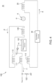
- FIG. 4 is a circuit diagram for explaining the connection between the coils.
- a detection signal Va output from the magnetosensitive element 101 is amplified by an amplifier 121 and supplied to the compensation coil 111.
- the compensation coil 111 acts to cancel a magnetic field to be applied to the magnetosensitive element 101 such that the detection signal Va from the magnetosensitive element 101 becomes zero. That is, the compensation coil 111 generates an opposite-phase magnetic field to the magnetic field to be applied to the magnetosensitive element 101 to thereby achieve closed-loop control.
- a compensation current i1 flowing in the compensation coil 111 is converted to an output signal Vout by a resistor 122 and output outside.
- the cancellation coil 112 is connected in series to the excitation coil 20.
- the excitation coil 20 is supplied with an excitation current i2 from an excitation circuit 30.
- the excitation current i2 is an AC signal having a predetermined frequency, whereby the excitation coil 20 generates an AC excitation magnetic field having a predetermined frequency.
- the AC excitation magnetic field generated by the excitation coil 20 vibrates the magnetic material P at a predetermined frequency, whereby the magnetic material P generates a primary magnetic field changing at a predetermined frequency.
- the AC excitation magnetic field itself from the excitation coil 20 acts as noise against the magnetosensitive element 101.
- the cancellation coil 112 cancels such noise, that is, cancels a component of the AC excitation magnetic field that can affect the magnetosensitive element 101.
- the cancellation coil 112 and excitation coil 20 are wound in mutually opposite directions.
- the transmitting coil 113 is connected in series to the receiving coil 120.
- the receiving coil 120 and transmitting coil 113 constitute a closed-loop circuit and are connected neither to an external circuit nor to an external power supply.
- the closed-loop circuit constituted by the receiving coil 120 and transmitting coil 113 may include a capacitor for phase adjustment.
- the receiving coil 120 converts the primary magnetic field generated from the magnetic material P to a detection current i3 and supplies this detection signal i3 to the transmitting coil 113.
- the transmitting coil 113 applies a secondary magnetic field to the magnetosensitive element 101 based on the detection current i3 supplied from the receiving coil 120.
- the magnetosensitive element 101 is not only directly applied with the primary magnetic field generated from the magnetic material P but also applied with the secondary magnetic field generated from the transmitting coil 113.
- the AC excitation magnetic field to be applied to the magnetosensitive element 101 is cancelled by the cancellation coil 112 as described above.
- the receiving coil 120 is disposed closer to the measurement area A than the magnetosensitive element 101 is as described above, so that even when the primary magnetic field applied to the magnetosensitive element 101 is feeble, high detection sensitivity can be achieved by the secondary magnetic field applied from the transmitting coil 113. This enhances an S/N ratio to allow detection of a feeble magnetic field.
- arranging a plurality of the magnetic sensors 100 in an array allows measurement of the two-dimensional distribution of the magnetic material P included within the measurement area A.
- the technology according to the present disclosure includes the following configuration examples but not limited thereto.
- a magnetic sensor includes: a magnetosensitive element; a cancellation coil that cancels a component of an AC excitation magnetic field, which is to be applied to a measurement target including a magnetic material, that can affect the magnetosensitive element; a receiving coil that receives a primary magnetic field generated from the magnetic material; and a transmitting coil that is connected to the receiving coil and applies a secondary magnetic field to the magnetosensitive element based on a detection current supplied from the receiving coil.
- the magnetosensitive element is not only directly applied with the primary magnetic field generated from the magnetic material but also applied with the secondary magnetic field generated from the transmitting coil, and further, the AC excitation magnetic field to be applied to the magnetosensitive element is cancelled by the cancellation coil, thus allowing achievement of a high S/N ratio.
- the above magnetic sensor may further include a magnetic field concentrator that focus a magnetic field on the magnetosensitive element, and the cancellation coil and transmitting coil may be wound around the magnetic field concentrator. This can enhance magnetic flux density to be applied to the magnetosensitive element.
- the above magnetic sensor may further include a compensation coil that cancels a magnetic field to be applied to the magnetosensitive element. This can achieve closed-loop control.
- the compensation coil may be wound around the magnetic field concentrator. This allows a compensation magnetic field to be effectively applied to the magnetosensitive element.
- the cancellation coil and transmitting coil may be wound outside the compensation coil. This allows the cancellation coil and transmitting coil to be adjusted afterward in terms of the number of turns and the like.
- a magnetic field measurement device includes the above-described magnetic sensor and an excitation coil that applies the AC excitation magnetic field to the magnetic material.
- an excitation coil that applies the AC excitation magnetic field to the magnetic material.
- a plurality of the magnetic sensors may be provided in an array. This allows measurement of two-dimensional distribution of the magnetic material.
Landscapes
- Physics & Mathematics (AREA)
- General Physics & Mathematics (AREA)
- Condensed Matter Physics & Semiconductors (AREA)
- Engineering & Computer Science (AREA)
- Chemical & Material Sciences (AREA)
- Nanotechnology (AREA)
- Health & Medical Sciences (AREA)
- Environmental & Geological Engineering (AREA)
- Toxicology (AREA)
- Measuring Magnetic Variables (AREA)
- Investigating Or Analyzing Materials By The Use Of Magnetic Means (AREA)
Abstract
Disclosed herein is a magnetic sensor that includes: a magnetosensitive element; a cancellation coil cancelling a component on the magnetosensitive element of an AC excitation magnetic field applied to a measurement target including a magnetic material; a receiving coil receiving a primary magnetic field generated from the magnetic material; and a transmitting coil connected to the receiving coil and applying a secondary magnetic field to the magnetosensitive element based on a detection current supplied from the receiving coil.
Description
- The present disclosure relates to a magnetic sensor and a magnetic field measurement device using the magnetic sensor and, more particularly, to a magnetic sensor capable of detecting a feeble magnetic field and a magnetic field measurement device using such a magnetic sensor.
- International Publication
WO 2021/100252 discloses a magnetic sensor capable of detecting a feeble magnetic field. - The magnetic sensor disclosed in International Publication
WO 2021/100252 has difficulty in ensuring a sufficient S/N ratio due to degradation of its detection sensitivity when distant from a measurement target increases. - The present disclosure describes an improved magnetic sensor capable of detecting a feeble magnetic field and a magnetic field measurement device using such a magnetic sensor.
- A magnetic sensor according to an aspect of the present disclosure includes: a magnetosensitive element; a cancellation coil cancelling a component on the magnetosensitive element of an AC excitation magnetic field applied to a measurement target including a magnetic material; a receiving coil receiving a primary magnetic field generated from the magnetic material; and a transmitting coil connected to the receiving coil and applying a secondary magnetic field to the magnetosensitive element based on a detection current supplied from the receiving coil.
- A magnetic field measurement device according to an aspect of the present disclosure includes the above-described magnetic sensor and an excitation coil that applies the AC excitation magnetic field to the magnetic material.
- According to the present disclosure, it is possible to obtain a high S/N ratio even when the distance between the measurement target and the magnetic sensing element is large.
- The above features and advantages of the present disclosure will be more apparent from the following description of certain preferred embodiments taken in conjunction with the accompanying drawings, in which:
-
FIG. 1 is a schematic view for explaining the configuration of a magneticfield measurement device 10 according to an embodiment of the present disclosure; -
FIG. 2 is a schematic diagram showing an example in which the measurement area A is located outside the inner diameter area of thereceiving coil 120; -
FIG. 3 is a schematic diagram showing a modification of themagnetic sensor 100; -
FIG. 4 is a circuit diagram for explaining the connection between the coils; and -
FIG. 5 is a schematic diagram showing an example in which a plurality ofmagnetic sensors 100 are arranged in an array. - Some embodiments of the present disclosure will be explained below in detail with reference to the accompanying drawings.
-
FIG. 1 is a schematic view for explaining the configuration of a magneticfield measurement device 10 according to an embodiment of the technology disclosed herein. - The magnetic
field measurement device 10 according to the present embodiment is a device for detecting a magnetic material P positioned within the measurement area A set in a measurement target and includes anexcitation coil 20 and amagnetic sensor 100 as illustrated inFIG. 1 . Theexcitation coil 20 applies an AC excitation magnetic field to the measurement target including the magnetic material P to magnetically or physically vibrate the magnetic material P at a predetermined frequency. The vibration of the magnetic material P appears as a change in a magnetic field generated from the magnetic material P. Themagnetic sensor 100 detects a change in the magnetic field. The magnetic material P may be nanosized magnetic nanoparticles. Using the magnetic nanoparticles as the magnetic material P allows a human body to be measured. The magneticfield measurement device 10 can also detect a metal member positioned within the measurement area A. When a metal member is present within the measurement area A, an eddy current is generated in the metal member by a magnetic field from theexcitation coil 20. The eddy current generates a new magnetic field, which is detected by themagnetic sensor 100. - The
magnetic sensor 100 includes amagnetosensitive element 101, amagnetic field concentrator 102 for focusing a magnetic field on themagnetosensitive element 101, acompensation coil 111 wound around themagnetic field concentrator 102, acancellation coil 112, atransmitting coil 113, and areceiving coil 120. - As the
magnetosensitive element 101, magnetoresistive effect elements such as a TMR (Tunnel Magneto-Resistive effect) element, a GMR (Giant Magneto-Resistive effect) element, and an AMR (Anisotropic Magneto-Resistive effect) element; a hall element; and an MI (Magnetic Impedance) element may be used. The sensitivity direction of themagnetosensitive element 101 is the X-direction, and themagnetic field concentrator 102 acts to collect a magnetic field in the X-direction. Although themagnetic field concentrator 102 need not necessarily be used in the present invention, it is preferably used in order to enhance magnetic flux density to be applied to themagnetosensitive element 101. - The
compensation coil 111,cancellation coil 112, and transmittingcoil 113 are wound around themagnetic field concentrator 102. The coil axis direction of thecompensation coil 111,cancellation coil 112, and transmittingcoil 113 is the X-direction. Thus, a magnetic field in the X-direction generated by a current flowing in thecompensation coil 111,cancellation coil 112, and transmittingcoil 113 is applied to themagnetosensitive element 101 through themagnetic field concentrator 102. - The
receiving coil 120 is disposed closer to the measurement area A than themagnetosensitive element 101 is. The coil axis direction of thereceiving coil 120 is also the X-direction, whereby a primary magnetic field generated from the magnetic material P is converted to a current by thereceiving coil 120. In the example ofFIG. 1 , the measurement area A is positioned in the inner diameter area of thereceiving coil 120; however, this is not essential, but as illustrated inFIG. 2 , the measurement area A may be positioned outside the inner diameter area of thereceiving coil 120. Even in this case, the distance between thereceiving coil 120 and the measurement area A in the X-direction is preferably smaller than the distance between themagnetosensitive element 101 and the measurement area A in the X-direction. - In the example of
FIG. 1 , the transmittingcoil 113,compensation coil 111, andcancellation coil 112 are arranged in the order of proximity to themagnetosensitive element 101; however, the arrangement order of thesecoils 111 to 113 is not particularly limited. Further, as in the example ofFIG. 3 , thecancellation coil 112 and transmittingcoil 113 may be wound outside thecompensation coil 111, which is wound around themagnetic field concentrator 102. With this configuration, themagnetic sensor 100 can be produced by winding thecancellation coil 112 and transmittingcoil 113 after preparing an assembly composed ofmagnetosensitive element 101,magnetic field concentrator 102, andcompensation coil 111, thus allowing thecancellation coil 112 and transmittingcoil 113 to be adjusted afterward in terms of the number of turns and winding position according to the characteristics of the magneticfield measurement device 10. Also, the size of themagnetic sensor 100 in the X-direction is reduced. -
FIG. 4 is a circuit diagram for explaining the connection between the coils. - As illustrated in
FIG. 4 , a detection signal Va output from themagnetosensitive element 101 is amplified by anamplifier 121 and supplied to thecompensation coil 111. Thecompensation coil 111 acts to cancel a magnetic field to be applied to themagnetosensitive element 101 such that the detection signal Va from themagnetosensitive element 101 becomes zero. That is, thecompensation coil 111 generates an opposite-phase magnetic field to the magnetic field to be applied to themagnetosensitive element 101 to thereby achieve closed-loop control. A compensation current i1 flowing in thecompensation coil 111 is converted to an output signal Vout by aresistor 122 and output outside. - The
cancellation coil 112 is connected in series to theexcitation coil 20. Theexcitation coil 20 is supplied with an excitation current i2 from anexcitation circuit 30. The excitation current i2 is an AC signal having a predetermined frequency, whereby theexcitation coil 20 generates an AC excitation magnetic field having a predetermined frequency. The AC excitation magnetic field generated by theexcitation coil 20 vibrates the magnetic material P at a predetermined frequency, whereby the magnetic material P generates a primary magnetic field changing at a predetermined frequency. However, the AC excitation magnetic field itself from theexcitation coil 20 acts as noise against themagnetosensitive element 101. Thecancellation coil 112 cancels such noise, that is, cancels a component of the AC excitation magnetic field that can affect themagnetosensitive element 101. To achieve this, thecancellation coil 112 andexcitation coil 20 are wound in mutually opposite directions. - The transmitting
coil 113 is connected in series to thereceiving coil 120. Thereceiving coil 120 and transmittingcoil 113 constitute a closed-loop circuit and are connected neither to an external circuit nor to an external power supply. The closed-loop circuit constituted by thereceiving coil 120 and transmittingcoil 113 may include a capacitor for phase adjustment. Thereceiving coil 120 converts the primary magnetic field generated from the magnetic material P to a detection current i3 and supplies this detection signal i3 to the transmittingcoil 113. The transmittingcoil 113 applies a secondary magnetic field to themagnetosensitive element 101 based on the detection current i3 supplied from thereceiving coil 120. Thus, themagnetosensitive element 101 is not only directly applied with the primary magnetic field generated from the magnetic material P but also applied with the secondary magnetic field generated from the transmittingcoil 113. The AC excitation magnetic field to be applied to themagnetosensitive element 101 is cancelled by thecancellation coil 112 as described above. - Further, the
receiving coil 120 is disposed closer to the measurement area A than themagnetosensitive element 101 is as described above, so that even when the primary magnetic field applied to themagnetosensitive element 101 is feeble, high detection sensitivity can be achieved by the secondary magnetic field applied from the transmittingcoil 113. This enhances an S/N ratio to allow detection of a feeble magnetic field. - Further, as illustrated in
FIG. 5 , arranging a plurality of themagnetic sensors 100 in an array allows measurement of the two-dimensional distribution of the magnetic material P included within the measurement area A. In this case, it is not necessary to provide a plurality of the excitation coils 20, and a plurality of themagnetic sensors 100 may be provided for oneexcitation coil 20. - While the preferred embodiment of the present disclosure has been described, the present disclosure is not limited to the above embodiment, and various modifications may be made within the scope of the present disclosure, and all such modifications are included in the present disclosure.
- The technology according to the present disclosure includes the following configuration examples but not limited thereto.
- A magnetic sensor according to an aspect of the present disclosure includes: a magnetosensitive element; a cancellation coil that cancels a component of an AC excitation magnetic field, which is to be applied to a measurement target including a magnetic material, that can affect the magnetosensitive element; a receiving coil that receives a primary magnetic field generated from the magnetic material; and a transmitting coil that is connected to the receiving coil and applies a secondary magnetic field to the magnetosensitive element based on a detection current supplied from the receiving coil. Thus, the magnetosensitive element is not only directly applied with the primary magnetic field generated from the magnetic material but also applied with the secondary magnetic field generated from the transmitting coil, and further, the AC excitation magnetic field to be applied to the magnetosensitive element is cancelled by the cancellation coil, thus allowing achievement of a high S/N ratio.
- The above magnetic sensor may further include a magnetic field concentrator that focus a magnetic field on the magnetosensitive element, and the cancellation coil and transmitting coil may be wound around the magnetic field concentrator. This can enhance magnetic flux density to be applied to the magnetosensitive element.
- The above magnetic sensor may further include a compensation coil that cancels a magnetic field to be applied to the magnetosensitive element. This can achieve closed-loop control.
- In the above magnetic sensor, the compensation coil may be wound around the magnetic field concentrator. This allows a compensation magnetic field to be effectively applied to the magnetosensitive element.
- In the above magnetic sensor, the cancellation coil and transmitting coil may be wound outside the compensation coil. This allows the cancellation coil and transmitting coil to be adjusted afterward in terms of the number of turns and the like.
- A magnetic field measurement device according to an aspect of the present disclosure includes the above-described magnetic sensor and an excitation coil that applies the AC excitation magnetic field to the magnetic material. Thus, there can be provided a magnetic field measurement device having a high S/N ratio.
- In the above magnetic field measurement device, a plurality of the magnetic sensors may be provided in an array. This allows measurement of two-dimensional distribution of the magnetic material.
Claims (5)
- A magnetic sensor comprising:a magnetosensitive element;a cancellation coil cancelling a component on the magnetosensitive element of an AC excitation magnetic field applied to a measurement target including a magnetic material;a receiving coil receiving a primary magnetic field generated from the magnetic material; anda transmitting coil connected to the receiving coil and applying a secondary magnetic field to the magnetosensitive element based on a detection current supplied from the receiving coil.
- The magnetic sensor as claimed in claim 1, further comprising a magnetic field concentrator that focus a magnetic field on the magnetosensitive element,
wherein the cancellation coil and transmitting coil are wound around the magnetic field concentrator. - The magnetic sensor as claimed in claim 2, further comprising a compensation coil cancelling a magnetic field to be applied to the magnetosensitive element.
- The magnetic sensor as claimed in claim 3, wherein the compensation coil is wound around the magnetic field concentrator.
- The magnetic sensor as claimed in claim 4, wherein the cancellation coil and transmitting coil are wound outside the compensation coil.
Applications Claiming Priority (1)
| Application Number | Priority Date | Filing Date | Title |
|---|---|---|---|
| JP2023053976A JP2024142025A (en) | 2023-03-29 | 2023-03-29 | Magnetic sensor and magnetic measurement device equipped with the same |
Publications (1)
| Publication Number | Publication Date |
|---|---|
| EP4443181A1 true EP4443181A1 (en) | 2024-10-09 |
Family
ID=90436497
Family Applications (1)
| Application Number | Title | Priority Date | Filing Date |
|---|---|---|---|
| EP24164810.4A Pending EP4443181A1 (en) | 2023-03-29 | 2024-03-20 | Magnetic sensor and magnetic field measurement device using the same |
Country Status (4)
| Country | Link |
|---|---|
| US (1) | US20240329159A1 (en) |
| EP (1) | EP4443181A1 (en) |
| JP (1) | JP2024142025A (en) |
| CN (1) | CN118731800A (en) |
Citations (6)
| Publication number | Priority date | Publication date | Assignee | Title |
|---|---|---|---|---|
| JPH06324021A (en) * | 1993-03-16 | 1994-11-25 | Hitachi Ltd | Non-destructive inspection device |
| JP3454237B2 (en) * | 1998-04-28 | 2003-10-06 | 株式会社日立製作所 | Biomagnetic field measurement device |
| US20080024126A1 (en) * | 2004-02-10 | 2008-01-31 | Matsushita Electric Industrial Co., Ltd. | Beam Measuring Equipment and Beam Measuring Method Using the Same |
| US20120229130A1 (en) * | 2005-04-29 | 2012-09-13 | University College London | Apparatus and Method for Determining Magnetic Properties of Materials |
| WO2021100252A1 (en) | 2019-11-22 | 2021-05-27 | Tdk株式会社 | Magnetic sensor |
| JP2022185470A (en) * | 2021-06-02 | 2022-12-14 | Tdk株式会社 | Magnetic measuring device |
-
2023
- 2023-03-29 JP JP2023053976A patent/JP2024142025A/en active Pending
-
2024
- 2024-03-20 EP EP24164810.4A patent/EP4443181A1/en active Pending
- 2024-03-22 US US18/613,739 patent/US20240329159A1/en active Pending
- 2024-03-28 CN CN202410366425.8A patent/CN118731800A/en active Pending
Patent Citations (7)
| Publication number | Priority date | Publication date | Assignee | Title |
|---|---|---|---|---|
| JPH06324021A (en) * | 1993-03-16 | 1994-11-25 | Hitachi Ltd | Non-destructive inspection device |
| JP3454237B2 (en) * | 1998-04-28 | 2003-10-06 | 株式会社日立製作所 | Biomagnetic field measurement device |
| US20080024126A1 (en) * | 2004-02-10 | 2008-01-31 | Matsushita Electric Industrial Co., Ltd. | Beam Measuring Equipment and Beam Measuring Method Using the Same |
| US20120229130A1 (en) * | 2005-04-29 | 2012-09-13 | University College London | Apparatus and Method for Determining Magnetic Properties of Materials |
| WO2021100252A1 (en) | 2019-11-22 | 2021-05-27 | Tdk株式会社 | Magnetic sensor |
| JP2022185470A (en) * | 2021-06-02 | 2022-12-14 | Tdk株式会社 | Magnetic measuring device |
| US20240248156A1 (en) * | 2021-06-02 | 2024-07-25 | Tdk Corporation | Magnetic field measurement device |
Also Published As
| Publication number | Publication date |
|---|---|
| JP2024142025A (en) | 2024-10-10 |
| CN118731800A (en) | 2024-10-01 |
| US20240329159A1 (en) | 2024-10-03 |
Similar Documents
| Publication | Publication Date | Title |
|---|---|---|
| KR101965977B1 (en) | Apparatus for measuring current | |
| US11199593B2 (en) | Magnetic sensor | |
| US8754642B2 (en) | Magnetic balance type current sensor | |
| JP7522129B2 (en) | Magnetic Sensors | |
| US10393775B2 (en) | Current-measuring device and method for determining an electric current | |
| JP3888427B2 (en) | Displacement sensor | |
| US20130300401A1 (en) | Sensor Apparatus, in Particular Metal Sensor, with a Field-Compensated Magnetic Field Sensor | |
| CN101563024B (en) | Arrangement and method for influencing and/or detecting magnetic particles in a region of action | |
| CN107462758B (en) | Closed loop current sensor | |
| US20100090688A1 (en) | Method and sensor arrangement for determining the position and/or change of position of a measured object relative to a sensor | |
| JP7115224B2 (en) | magnetic sensor | |
| US7859259B2 (en) | Magnetic filed compensation system with increased bandwidth | |
| JP2008215970A (en) | Bus bar integrated current sensor | |
| CN115667966B (en) | Magnetic field detection device and magnetic field detection device array | |
| CN110687339B (en) | current sensor | |
| US20240329159A1 (en) | Magnetic sensor and magnetic field measurement device using the same | |
| JP6008756B2 (en) | Current sensor and three-phase AC current sensor device | |
| JPH0618568A (en) | Current sensor | |
| JP7479888B2 (en) | Magnetic Field Detection Device | |
| EP4610682A2 (en) | Magnetic sensor | |
| US7498804B1 (en) | Resonance current sensing | |
| JPH09159454A (en) | Electronic direction detection apparatus for moving body | |
| JP2003149308A (en) | Magnetic field measurement device | |
| JPH0247908A (en) | Superconducting magnetism sensor | |
| JP2003302250A (en) | Circuit for displacement meter |
Legal Events
| Date | Code | Title | Description |
|---|---|---|---|
| PUAI | Public reference made under article 153(3) epc to a published international application that has entered the european phase |
Free format text: ORIGINAL CODE: 0009012 |
|
| STAA | Information on the status of an ep patent application or granted ep patent |
Free format text: STATUS: THE APPLICATION HAS BEEN PUBLISHED |
|
| AK | Designated contracting states |
Kind code of ref document: A1 Designated state(s): AL AT BE BG CH CY CZ DE DK EE ES FI FR GB GR HR HU IE IS IT LI LT LU LV MC ME MK MT NL NO PL PT RO RS SE SI SK SM TR |
|
| STAA | Information on the status of an ep patent application or granted ep patent |
Free format text: STATUS: REQUEST FOR EXAMINATION WAS MADE |
|
| 17P | Request for examination filed |
Effective date: 20250407 |