EP4443157A1 - Air quality analysis device - Google Patents
Air quality analysis device Download PDFInfo
- Publication number
- EP4443157A1 EP4443157A1 EP24159481.1A EP24159481A EP4443157A1 EP 4443157 A1 EP4443157 A1 EP 4443157A1 EP 24159481 A EP24159481 A EP 24159481A EP 4443157 A1 EP4443157 A1 EP 4443157A1
- Authority
- EP
- European Patent Office
- Prior art keywords
- air quality
- air flow
- chamber
- sensor
- sensors
- Prior art date
- Legal status (The legal status is an assumption and is not a legal conclusion. Google has not performed a legal analysis and makes no representation as to the accuracy of the status listed.)
- Pending
Links
Images




Classifications
-
- G—PHYSICS
- G01—MEASURING; TESTING
- G01N—INVESTIGATING OR ANALYSING MATERIALS BY DETERMINING THEIR CHEMICAL OR PHYSICAL PROPERTIES
- G01N33/00—Investigating or analysing materials by specific methods not covered by groups G01N1/00 - G01N31/00
- G01N33/0004—Gaseous mixtures, e.g. polluted air
- G01N33/0009—General constructional details of gas analysers, e.g. portable test equipment
- G01N33/0027—General constructional details of gas analysers, e.g. portable test equipment concerning the detector
- G01N33/0031—General constructional details of gas analysers, e.g. portable test equipment concerning the detector comprising two or more sensors, e.g. a sensor array
- G01N33/0032—General constructional details of gas analysers, e.g. portable test equipment concerning the detector comprising two or more sensors, e.g. a sensor array using two or more different physical functioning modes
-
- G—PHYSICS
- G01—MEASURING; TESTING
- G01N—INVESTIGATING OR ANALYSING MATERIALS BY DETERMINING THEIR CHEMICAL OR PHYSICAL PROPERTIES
- G01N33/00—Investigating or analysing materials by specific methods not covered by groups G01N1/00 - G01N31/00
- G01N33/0004—Gaseous mixtures, e.g. polluted air
- G01N33/0009—General constructional details of gas analysers, e.g. portable test equipment
-
- A—HUMAN NECESSITIES
- A61—MEDICAL OR VETERINARY SCIENCE; HYGIENE
- A61M—DEVICES FOR INTRODUCING MEDIA INTO, OR ONTO, THE BODY; DEVICES FOR TRANSDUCING BODY MEDIA OR FOR TAKING MEDIA FROM THE BODY; DEVICES FOR PRODUCING OR ENDING SLEEP OR STUPOR
- A61M16/00—Devices for influencing the respiratory system of patients by gas treatment, e.g. ventilators; Tracheal tubes
- A61M16/10—Preparation of respiratory gases or vapours
- A61M16/1005—Preparation of respiratory gases or vapours with O2 features or with parameter measurement
-
- G—PHYSICS
- G01—MEASURING; TESTING
- G01N—INVESTIGATING OR ANALYSING MATERIALS BY DETERMINING THEIR CHEMICAL OR PHYSICAL PROPERTIES
- G01N15/00—Investigating characteristics of particles; Investigating permeability, pore-volume or surface-area of porous materials
- G01N15/02—Investigating particle size or size distribution
-
- G—PHYSICS
- G01—MEASURING; TESTING
- G01N—INVESTIGATING OR ANALYSING MATERIALS BY DETERMINING THEIR CHEMICAL OR PHYSICAL PROPERTIES
- G01N15/00—Investigating characteristics of particles; Investigating permeability, pore-volume or surface-area of porous materials
- G01N15/06—Investigating concentration of particle suspensions
-
- G—PHYSICS
- G01—MEASURING; TESTING
- G01N—INVESTIGATING OR ANALYSING MATERIALS BY DETERMINING THEIR CHEMICAL OR PHYSICAL PROPERTIES
- G01N21/00—Investigating or analysing materials by the use of optical means, i.e. using sub-millimetre waves, infrared, visible or ultraviolet light
- G01N21/17—Systems in which incident light is modified in accordance with the properties of the material investigated
- G01N21/25—Colour; Spectral properties, i.e. comparison of effect of material on the light at two or more different wavelengths or wavelength bands
- G01N21/27—Colour; Spectral properties, i.e. comparison of effect of material on the light at two or more different wavelengths or wavelength bands using photo-electric detection ; circuits for computing concentration
-
- G—PHYSICS
- G01—MEASURING; TESTING
- G01N—INVESTIGATING OR ANALYSING MATERIALS BY DETERMINING THEIR CHEMICAL OR PHYSICAL PROPERTIES
- G01N33/00—Investigating or analysing materials by specific methods not covered by groups G01N1/00 - G01N31/00
- G01N33/0004—Gaseous mixtures, e.g. polluted air
-
- G—PHYSICS
- G01—MEASURING; TESTING
- G01N—INVESTIGATING OR ANALYSING MATERIALS BY DETERMINING THEIR CHEMICAL OR PHYSICAL PROPERTIES
- G01N33/00—Investigating or analysing materials by specific methods not covered by groups G01N1/00 - G01N31/00
- G01N33/0004—Gaseous mixtures, e.g. polluted air
- G01N33/0009—General constructional details of gas analysers, e.g. portable test equipment
- G01N33/0027—General constructional details of gas analysers, e.g. portable test equipment concerning the detector
- G01N33/0031—General constructional details of gas analysers, e.g. portable test equipment concerning the detector comprising two or more sensors, e.g. a sensor array
-
- G—PHYSICS
- G01—MEASURING; TESTING
- G01N—INVESTIGATING OR ANALYSING MATERIALS BY DETERMINING THEIR CHEMICAL OR PHYSICAL PROPERTIES
- G01N33/00—Investigating or analysing materials by specific methods not covered by groups G01N1/00 - G01N31/00
- G01N33/0004—Gaseous mixtures, e.g. polluted air
- G01N33/0009—General constructional details of gas analysers, e.g. portable test equipment
- G01N33/0027—General constructional details of gas analysers, e.g. portable test equipment concerning the detector
- G01N33/0036—General constructional details of gas analysers, e.g. portable test equipment concerning the detector specially adapted to detect a particular component
- G01N33/0047—Organic compounds
-
- A—HUMAN NECESSITIES
- A61—MEDICAL OR VETERINARY SCIENCE; HYGIENE
- A61M—DEVICES FOR INTRODUCING MEDIA INTO, OR ONTO, THE BODY; DEVICES FOR TRANSDUCING BODY MEDIA OR FOR TAKING MEDIA FROM THE BODY; DEVICES FOR PRODUCING OR ENDING SLEEP OR STUPOR
- A61M16/00—Devices for influencing the respiratory system of patients by gas treatment, e.g. ventilators; Tracheal tubes
- A61M16/10—Preparation of respiratory gases or vapours
- A61M16/14—Preparation of respiratory gases or vapours by mixing different fluids, one of them being in a liquid phase
- A61M16/16—Devices to humidify the respiration air
- A61M16/161—Devices to humidify the respiration air with means for measuring the humidity
-
- A—HUMAN NECESSITIES
- A61—MEDICAL OR VETERINARY SCIENCE; HYGIENE
- A61M—DEVICES FOR INTRODUCING MEDIA INTO, OR ONTO, THE BODY; DEVICES FOR TRANSDUCING BODY MEDIA OR FOR TAKING MEDIA FROM THE BODY; DEVICES FOR PRODUCING OR ENDING SLEEP OR STUPOR
- A61M16/00—Devices for influencing the respiratory system of patients by gas treatment, e.g. ventilators; Tracheal tubes
- A61M16/10—Preparation of respiratory gases or vapours
- A61M16/1005—Preparation of respiratory gases or vapours with O2 features or with parameter measurement
- A61M2016/102—Measuring a parameter of the content of the delivered gas
-
- A—HUMAN NECESSITIES
- A61—MEDICAL OR VETERINARY SCIENCE; HYGIENE
- A61M—DEVICES FOR INTRODUCING MEDIA INTO, OR ONTO, THE BODY; DEVICES FOR TRANSDUCING BODY MEDIA OR FOR TAKING MEDIA FROM THE BODY; DEVICES FOR PRODUCING OR ENDING SLEEP OR STUPOR
- A61M2205/00—General characteristics of the apparatus
- A61M2205/18—General characteristics of the apparatus with alarm
-
- A—HUMAN NECESSITIES
- A61—MEDICAL OR VETERINARY SCIENCE; HYGIENE
- A61M—DEVICES FOR INTRODUCING MEDIA INTO, OR ONTO, THE BODY; DEVICES FOR TRANSDUCING BODY MEDIA OR FOR TAKING MEDIA FROM THE BODY; DEVICES FOR PRODUCING OR ENDING SLEEP OR STUPOR
- A61M2205/00—General characteristics of the apparatus
- A61M2205/33—Controlling, regulating or measuring
- A61M2205/3368—Temperature
-
- A—HUMAN NECESSITIES
- A61—MEDICAL OR VETERINARY SCIENCE; HYGIENE
- A61M—DEVICES FOR INTRODUCING MEDIA INTO, OR ONTO, THE BODY; DEVICES FOR TRANSDUCING BODY MEDIA OR FOR TAKING MEDIA FROM THE BODY; DEVICES FOR PRODUCING OR ENDING SLEEP OR STUPOR
- A61M2205/00—General characteristics of the apparatus
- A61M2205/50—General characteristics of the apparatus with microprocessors or computers
- A61M2205/502—User interfaces, e.g. screens or keyboards
- A61M2205/505—Touch-screens; Virtual keyboard or keypads; Virtual buttons; Soft keys; Mouse touches
-
- G—PHYSICS
- G01—MEASURING; TESTING
- G01N—INVESTIGATING OR ANALYSING MATERIALS BY DETERMINING THEIR CHEMICAL OR PHYSICAL PROPERTIES
- G01N15/00—Investigating characteristics of particles; Investigating permeability, pore-volume or surface-area of porous materials
- G01N2015/0042—Investigating dispersion of solids
- G01N2015/0046—Investigating dispersion of solids in gas, e.g. smoke
Definitions
- Embodiments of the present disclosure relate generally to an air quality analysis device and a method of performing air quality analysis.
- Applicant has identified many technical challenges and difficulties associated with air quality analysis. Through applied effort, ingenuity, and innovation, Applicant has solved problems related to air quality analysis by developing solutions embodied in the present disclosure, which are described in detail below.
- Various embodiments described herein relate to an air quality analysis device and a method of performing air quality analysis.
- air quality analysis device includes a housing having a chamber comprising an inlet port.
- the inlet port is structured to receive an air flow into the chamber.
- air quality analysis device includes a plurality of sensors disposed within the chamber and configured to generate air quality data associated with the air flow.
- the plurality of sensors comprises at least one mold sensor.
- air quality analysis device includes a printed circuit board in communication with the plurality of sensors and configured to transmit the air quality data to a computing device.
- the plurality of sensors further comprises at least one of a particulate matter sensor, a volatile organic compound sensor, a humidity sensor, or a temperature sensor.
- the particulate matter sensor is configured to generate air quality data indicating that there are particles having a diameter of less than 2.5 microns or 10 microns in the air flow.
- the plurality of sensors further comprises a first volatile organic compound sensor and a second volatile organic compound sensor.
- the first volatile organic compound sensor is configured to generate air quality data indicating that there is a first volatile organic compound in the air flow and the second volatile organic compound sensor is configured to generate air quality data indicating that there is a second volatile organic compound in the air flow.
- the at least one mold sensor comprises a spectrometer.
- the at least one mold sensor is configured to generate air quality data indicating a probability of mold being in the air flow based at least on a humidity associated with the air flow, a temperature associated with the air flow, a particle concentration associated with the air flow, and a cleaning date associated with the air flow.
- the chamber comprises an outlet port structured to discharge the air flow from the chamber.
- inlet port is structured to receive the air flow into the chamber from a tube associated with a continuous positive airway pressure machine and the outlet port is structured to discharge the air flow from the chamber into a face mask associated with the continuous positive airway pressure machine.
- inlet port is structured to receive the air flow into the chamber from a blower of a continuous positive airway pressure machine and the outlet port is structured to discharge the air flow from the chamber into a tube associated with the continuous positive airway pressure machine.
- the chamber comprises a first portion and a second portion.
- the plurality of sensors is disposed in the first portion.
- the computing device comprises a user interface configured display an instruction indicating that a user should clean a continuous positive airway pressure machine associated with the user.
- a method of performing air quality analysis may include receiving air quality data from an air quality analysis device.
- air quality analysis device includes a housing having a chamber comprising an inlet port.
- the inlet port is structured to receive an air flow into the chamber.
- air quality analysis device includes a plurality of sensors disposed within the chamber and configured to generate air quality data associated with the air flow.
- the plurality of sensors comprises at least one mold sensor.
- air quality analysis device includes a printed circuit board in communication with the plurality of sensors and configured to transmit the air quality data to a computing device.
- the method of performing an air quality analysis may include causing a user interface to display an instruction to a user associated with a continuous positive airway pressure machine instructing the user to clean the continuous positive airway pressure machine.
- the plurality of sensors further comprises at least one of a particulate matter sensor, a volatile organic compound sensor, a humidity sensor, or a temperature sensor.
- the particulate matter sensor is configured to generate air quality data indicating that there are particles having a diameter of less than 2.5 microns or 10 microns in the air flow.
- the plurality of sensors further comprises a first volatile organic compound sensor and a second volatile organic compound sensor.
- the first volatile organic compound sensor is configured to generate air quality data indicating that there is a first volatile organic compound in the air flow and the second volatile organic compound sensor is configured to generate air quality data indicating that there is a second volatile organic compound in the air flow.
- the at least one mold sensor comprises a spectrometer.
- the at least one mold sensor is configured to generate air quality data indicating a probability of mold being in the air flow based at least on a humidity associated with the air flow, a temperature associated with the air flow, a particle concentration associated with the air flow, and a cleaning date associated with the air flow.
- the chamber comprises an outlet port structured to discharge the air flow from the chamber.
- inlet port is structured to receive the air flow into the chamber from a tube associated with the continuous positive airway pressure machine and the outlet port is structured to discharge the air flow from the chamber into a face mask associated with the continuous positive airway pressure machine.
- inlet port is structured to receive the air flow into the chamber from a blower of the continuous positive airway pressure machine and the outlet port is structured to discharge the air flow from the chamber into a tube associated with the continuous positive airway pressure machine.
- the chamber comprises a first portion and a second portion.
- the plurality of sensors is disposed in the first portion.
- Example embodiments disclosed herein address technical problems associated with air quality analysis devices and methods of performing air quality analysis. As would be understood by one skilled in the field to which this disclosure pertains, there are numerous example scenarios in which a user may use an air quality analysis device and methods of performing air quality analysis. For example, it may be necessary to use an air quality analysis device to generate air quality data of air flow associated with a continuous positive airway pressure (CPAP) machine that indicates that there is a probably of mold being in the air flow and/or the CPAP machine.
- CPAP continuous positive airway pressure
- a CPAP machine for example, provides a flow of pressurized air that, in some examples, is also heated and humified, to a user's upper airway while the user is sleeping to ensure that the user's upper airway is not obstructed so the user can obtain enough oxygen while sleeping.
- CPAP machines due to the frequent use of CPAP machines (e.g., every night), the humidification of the air flow, the heating of the air flow, and/or infrequent cleaning by a user of the CPAP machine, CPAP machines often develop mold, resulting in the user being exposed to mold when using the CPAP machine. Accordingly, there is a need for devices and methods that can generate air quality data associated with the air flow provided by CPAP machines to users to ensure that the users do not breath in air flow having mold in it.
- an air quality analysis device having a housing having a chamber comprising an inlet port.
- the inlet port is structured to receive an air flow into the chamber.
- the air quality analysis device may include a plurality of sensors disposed within the chamber and configured to generate air quality data associated with the air flow.
- the plurality of sensors comprises at least one mold sensor.
- the air quality analysis device may include a printed circuit board in communication with the plurality of sensors and configured to transmit the air quality data to a computing device. As such, the air quality of air flow provided by CPAP machines may be analyzed to ensure that a user of the CPAP machine does not breath in air flow provided by the CPAP machine having mold in it.
- the air quality analysis device 100 may be configured to generate air quality data associated with an air flow.
- the air quality analysis device 100 may be configured to generate air quality data associated with air flow provided by a continuous positive pressure machine (CPAP) machine 120.
- CPAP continuous positive pressure machine
- the air quality analysis device 100 may be used to generate air quality data associated with air flow provided by any type of positive airway pressure machine, such as automatic positive airway pressure (APAP) machines, bilevel positive airway pressure (BiPAP) machines, adaptive servo-ventilation (ASV) machines, other mechanical ventilation machines, and/or the like.
- APAP automatic positive airway pressure
- BiPAP bilevel positive airway pressure
- ASV adaptive servo-ventilation
- other mechanical ventilation machines and/or the like.
- the air quality analysis device 100 may include a housing 102.
- the housing 102 may be substantially cubical, substantially rectangular, and/or substantially cylindrical.
- the housing 102 may include a chamber 104.
- the chamber 104 may be substantially cubical, substantially rectangular, and/or substantially cylindrical.
- the chamber 104 may be substantially the same shape as the housing 102.
- the chamber 104 may not be substantially the same shape as the housing 102.
- the housing 102 and/or the chamber 104 may be comprised of plastic or any other suitable material.
- the housing 102 and/or the chamber 104 may be constructed using injection molding and/or 3D printing.
- the chamber 104 may have an inlet port 106 and/or an outlet port 108.
- the inlet port 106 may be configured to receive air flow into the chamber 104 and the outlet port 108 may be configured to discharge air flow into the chamber 104 (e.g., the air flow moves through the chamber 104 from the inlet port 106 to the outlet port 108).
- the inlet port 106 may be structured to receive the air flow into the chamber 104 from a blower 122 of the CPAP machine 120 and the outlet port 108 may be structured to discharge the air to a tube 124 associated with the CPAP machine 120 (e.g., the inlet port 106 may be structured to be attached to the blower 122 of the CPAP machine 120 and the outlet port 108 may be structured to be attached to the tube 124 associated with the CPAP machine 120).
- the inlet port 106 may be structured to receive the air flow into the chamber 104 from the tube 124 of the CPAP machine 120 and the outlet port 108 may be structured to discharge the air to a face mask 126 associated with the CPAP machine 120 (e.g., the inlet port 106 may be structured to be attached to the tube 124 of the CPAP machine 120 and the outlet port 108 may be structured to be attached to the face mask 126 associated with the CPAP machine 120).
- the air quality analysis device 100 may include a plurality of sensors 110 disposed in the chamber 104.
- the plurality of sensors 110 may be disposed in the chamber 104 in any manner that enables the plurality of sensors 110 to generate air quality data associated with the air flow.
- the plurality of sensors 110 may be disposed in the chamber 104 in any manner that enables each of the plurality of sensors 110 to be able to interact with the air flow such that each of the plurality of sensors 110 can generate air quality data associated with the air flow.
- the plurality of sensors 110 may be disposed on an interior surface 114 of the chamber 104.
- FIGS. 1 such as illustrated in FIGS.
- the plurality of sensors 110 may be disposed in a first portion 116 of the chamber 104. That is, the plurality of sensors 110 may all be disposed in a first portion 116 of the chamber 104 and none of the plurality of sensors 110 may be disposed in a second portion 118 of the chamber 104.
- the plurality of sensors 110 may be configured to generate air quality data associated with the air flow.
- the plurality of sensors 110 may be configured to generate air quality data associated with the air flow by generating air quality data indicating a probability of mold in the air flow, generating air quality data indicating that there are particles in the air flow having a particular size, generating air quality data indicating volatile organic compounds in the air flow, generating air quality data indicating a humidity associated with the air flow, and/or generating air quality data indicating a temperature associated with the air flow.
- the plurality of sensors 110 determine a probability that mold is present in the air flow, particles of a particular size are present in the air flow, and/or volatile organic compounds are in the air flow.
- the air quality data may indicate that mold, particles of a particular size, and/or volatile organic compounds are present in the CPAP machine 120, the tube 124, and/or the face mask 126.
- the plurality of sensors 110 may include at least one mold sensor.
- the plurality of sensors 110 may include at least one mold sensor configured to generate air quality data indicating a probability of mold in the air flow (e.g., is mold present in the air flow).
- the at least one mold sensor may include a spectrometer configured to generate air quality data indicating a probability of mold in the air flow.
- the at least one mold sensor may be configured to generate air quality data indicating a probability of mold in the air flow based on one or more of humidity associated with the air flow, a temperature associated with the air flow, a particle concentration associated with the air flow, and a cleaning date associated with the air flow.
- the mold sensor may be configured to generate air quality data that there is a probability mold in the air flow when the humidity associated with the air flow is a above a humidity threshold (e.g., above 95%) and the cleaning date associated with the air flow indicates that it has been a greater amount of time than a cleaning time threshold (e.g., it has been 6 months since the CPAP Machine 120 has been cleaned and the cleaning time threshold is 3 months).
- a humidity threshold e.g., above 95%)
- the cleaning date associated with the air flow indicates that it has been a greater amount of time than a cleaning time threshold (e.g., it has been 6 months since the CPAP Machine 120 has been cleaned and the cleaning time threshold is 3 months).
- the at least one mold sensor may be configured to determine that the probability mold is present in the air flow is low, medium, or high that mold is present in the air flow.
- the plurality of sensors 110 may include at least one particulate matter sensor.
- the plurality of sensors 110 may include at least one particulate matter sensor configured to generate air quality data indicating that there are particles in the air flow (e.g., how many particles in the air flow, concentration of particles in the air flow, size of particles in the air flow, etc.), such as particles having a diameter of less than 2.5 microns and/or 10 microns.
- the plurality of sensors 110 may include a first particulate matter sensor to generate air quality data indicating that there are particles having a diameter of 2.5 microns or less and/or a second particulate matter sensor to generate air quality data indicating that there are particles having a diameter of 10 microns or less.
- the plurality of sensors 110 may include a particulate matter sensor that is configured to generate air quality data indicating that there are multiple particles of multiple diameters, such as a particulate matter sensor that can generate air quality data indicating that there are particles having a diameter of 2.5 microns or less and/or particles have a diameter of 10 microns or less.
- the plurality of sensors 110 may include at least one volatile organic compound sensor.
- the plurality of sensors 110 may include at least one volatile organic compound sensor that configured to generate air quality data indicating volatile organic compounds in the air flow, such as one or more of benzene, ethylene glycol, formaldehyde, acetone, methylene chloride, tetrachloroethylene, toluene, xylene, and/or 1,3-butadiene.
- the plurality of sensors 110 may include volatile organic compound sensors that are each configured to generate air quality data indicating that there are a specific volatile organic compound is in the air flow.
- the plurality of sensors 110 may include a first volatile organic compound sensor configured to generate air quality data indicating that there is a first volatile organic compound in the air flow, such as benzene, and a second volatile organic compound sensor configured to generate air quality data indicating that there is a second volatile organic compound, such as acetone.
- the plurality of sensors 110 may include a volatile organic compound sensor that is configured to generate air quality data indicating that there are more than one volatile organic compound in the air flow.
- the plurality of sensors 110 may include at least one humidity sensor.
- the plurality of sensors 110 may include at least one humidity sensor that can generate air quality data indicating a humidity associated with the air flow.
- the at least one humidity sensor may generate air quality data indicating that the air flow is associated with a 90% humidity.
- the plurality of sensors 110 may include at least one temperature sensor.
- the plurality of sensors 110 may include at least one temperature sensor that can generate air quality data indicating a temperature associated with the air flow.
- the at least one temperature sensor may generate air quality data indicating that the air flow has a temperature of 90 degrees.
- the air quality data generated by the plurality of sensors 110 may be obtained and stored in a structured and/or in an unstructured data format.
- the air quality data may indicate that the probability of mold being in the air flow is low, medium, or high mold is present in the air flow based on the air quality data generated made by the mold sensor.
- the air quality data may include a count of the number of times the at least one particulate matter sensor generated air quality data indicating that particles of a particular size are in the air flow (e.g., the at least one particulate matter sensor counted 25 particles with a size of 2.5 microns or less in the air flow).
- the air quality data may include an indication of whether or not the at least one volatile organic compound sensor generated air quality data indicating that a specific volatile organic compound is in the air flow (e.g., the at least one volatile organic compound sensor generated air quality data indicating that formaldehyde is in the air flow).
- the air quality data may include a temperature and a humidity associated with the air flow as generated by the at least one temperature sensor and/or humidity sensor.
- the air quality analysis device 100 may include a printed circuit board (PCB) 112.
- the PCB 112 may be disposed proximate the plurality of sensors 110. For example, if the plurality of sensors 110 is disposed on the interior surface 114 of the chamber 104, such as illustrated in FIGS. 2 and 3 , the PCB 112 may be disposed on the interior surface 114 of the chamber 104. Additionally or alternatively, if the plurality of sensors is disposed in the first portion 116 of the chamber 104, such as illustrated in FIGS. 4 and 5 , the PCB may be disposed in the first portion 116 of the chamber 104.
- the PCB 112 may be in electrical communication with the plurality of sensors 110 and be configured to transmit the air quality data generated by the plurality of sensors 110 to a computing device 128. In some embodiments, the PCB 112 may transmit the air quality data generated by the plurality of sensors 110 to the computing device 128 via Wi-Fi and/or Bluetooth. In some embodiments, the PCB 112 may be configured to transmit the air quality data to the computing device in real-time. For example, each time the at least one volatile organic compound sensor generated air quality data indicating that a volatile organic compound is in the air flow, the PCB 112 may transmit generated air quality data to the computing device 128.
- the PCB 112 may be configured to transmit the air quality data to the computing device 128 on a pre-determined schedule. For example, the PCB 112 may transmit the air quality data to the computing device 128 every 20 seconds. In some embodiments, the PCB 112 may be configured to transmit the air quality data to the computing device 128 at the end of an analysis period. For example, the PCB 112 may be configured to identify when air flow has started flowing through the chamber 104 and when air flow has stopped flowing through the chamber 104. In this regard, when the PCB 112 has identified that the air flow has stopped flowing through the chamber 104, the PCB 112 may transmit the air quality data to the computing device 128. In some embodiments, the PCB 112 may be configured to transmit the air quality data to the computing device 128 upon receiving an instruction to transmit the air quality data from the computing device 128.
- the computing device 128 may include a user interface 602.
- the user interface 602 may be provided by a mobile application executing on the computing device 128.
- the user interface 602 may include an air quality data component 604 configured to indicate air quality data generated by the plurality of sensors 110.
- the air quality data component 604 may indicate that the probability that there is mold in the air flow is low, medium, or high, the CPAP machine 120, the tube 124, and/or the face mask 126 if the at least one mold sensor determines that the probability that there is mold in the air flow is low, medium, or high.
- the air quality data component 604 may indicate a count of the number of times the at least one particulate matter sensor generated air quality data indicating particles of a particular size and the size of the particles in the air flow, the CPAP machine 120, the tube 124, and/or the face mask 126 if the at least one particulate matter sensor determines a count of the number of times the at least one particulate matter sensor generated air quality data indicating particles of a particular size and the size of the particles in the air flow.
- the air quality data component 604 may indicate that there is an at least one volatile organic compound sensor in the air flow, the CPAP machine 120, the tube 124, and/or the face mask 126 if the at least one volatile organic compound sensor generated air quality data indicating a specific volatile organic compound is in the air flow (e.g., the at least one volatile organic compound sensor generated air quality data indicating formaldehyde is in the air flow).
- the air quality data component 604 may indicate a humidity and/or temperature associated with the air flow the CPAP machine 120, the tube 124, and/or the face mask 126 based on air quality data indicating a humidity of the air flow generated by the at least one humidity sensor and/or air quality data indicating a temperature of the air flow generated by the at least one temperature sensor.
- the user interface 602 may include a cleaning component 606 configured to display an instruction indicating that the CPAP machine 120, the tube 124, and/or the face mask 126 should be cleaned.
- the cleaning component 606 may display an instruction indicating that the CPAP machine 120, the tube 124, and/or the face mask 126 should be cleaned if the probability that mold is present in the air flow, the CPAP machine 120, the tube 124, and/or the face mask 126 is medium or high.
- the cleaning component 606 may display an instruction indicating that the CPAP machine 120, the tube 124, and/or the face mask 126 should be cleaned if a count of the number of times the at least one particulate matter sensor generated air quality data indicating particles of a particular size in the air flow the CPAP machine 120, the tube 124, and/or the face mask 126 is above a particle threshold.
- the cleaning component 606 may display an instruction indicating that the CPAP machine 120, the tube 124, and/or the face mask 126 should be cleaned if the at least one volatile organic compound sensor generated air quality data indicating a specific volatile organic compound (e.g., the at least one volatile organic compound sensor generated air quality data indicating formaldehyde is in the air flow) is in the air flow.
- a specific volatile organic compound e.g., the at least one volatile organic compound sensor generated air quality data indicating formaldehyde is in the air flow
- the cleaning component 606 may display an instruction indicating that the CPAP machine 120, the tube 124, and/or the face mask 126 should be cleaned if a temperature and a humidity and/or temperature associated with the air flow the CPAP machine 120, the tube 124, and/or the face mask 126 if a humidity of the air flow is above a humidity threshold and/or a temperature of the air flow is above a temperature threshold.
- FIG. 7 a flowchart providing an example method 700 of performing air quality analysis is illustrated.
- FIG. 7 illustrates operations that may be performed by the computing device 128 and/or the air quality analysis device 100.
- the method 700 of performing air quality analysis may include receiving air quality data from an air quality analysis device.
- the air quality analysis device may include a housing.
- the housing may include a chamber.
- the housing and/or the chamber may be comprised of plastic or any other suitable material.
- the housing and/or the chamber may be constructed using injection molding and/or 3D printing.
- the chamber may have an inlet port and/or an outlet port.
- the inlet port may be configured to receive air flow into the chamber and the outlet port may be configured to discharge air flow into the chamber (e.g., the air flow moves through the chamber from the inlet port to the outlet port).
- the inlet port may be structured to receive the air flow into the chamber from a blower of the CPAP machine and the outlet port may be structured to discharge the air to a tube associated with the CPAP machine (e.g., the inlet port may be structured to be attached to the blower of the CPAP machine and the outlet port may be structured to be attached to the tube associated with the CPAP machine).
- the inlet port may be structured to receive the air flow into the chamber from the tube of the CPAP machine and the outlet port may be structured to discharge the air to a face mask associated with the CPAP machine (e.g., the inlet port may be structured to be attached to the tube of the CPAP machine and the outlet port may be structured to be attached to the face mask associated with the CPAP machine).
- the air quality analysis device may include a plurality of sensors disposed in the chamber.
- the plurality of sensors may be disposed in the chamber in any manner that enables the plurality of sensors to generate air quality data associated with the air flow.
- the plurality of sensors may be disposed in the chamber in any manner that enables each of the plurality of sensors to be able to interact with the air flow such that each of the plurality of sensors can generate air quality data associated with the air flow.
- the plurality of sensors may be disposed on an interior surface of the chamber.
- the plurality of sensors may be disposed in a first portion of the chamber. That is, the plurality of sensors may all be disposed in a first portion of the chamber and none of the plurality of sensors may be disposed in a second portion of the chamber.
- the plurality of sensors may be configured to generate air quality data associated with the air flow.
- the plurality of sensors may be configured to generate air quality data associated with the air flow by generating air quality data indicating that there is a probability of mold in the air flow, generating air quality data indicating particles in the air flow having a particular size, generating air quality data indicating volatile organic compounds in the air flow, generating air quality data indicating a humidity associated with the air flow, and/or generating air quality data indicating a temperature associated with the air flow.
- the plurality of sensors based on air quality data generated by the plurality of sensors, determine that a probability of mold being in the air flow, particles of a particular size are present in the air flow, and/or volatile organic compounds are in the air flow, it may indicate that mold, particles of a particular size, and/or volatile organic compounds are present in the CPAP machine, the tube, and/or the face mask.
- the air quality data generated by the plurality of sensors may be obtained and stored in a structured and/or in an unstructured data format.
- the air quality analysis device may include a printed circuit board (PCB).
- the PCB may be disposed proximate the plurality of sensors. For example, if the plurality of sensors is disposed on the interior surface of the chamber the PCB may be disposed on the interior surface of the chamber. Additionally or alternatively, if the plurality of sensors is disposed in the first portion of the chamber the PCB may be disposed in the first portion of the chamber.
- the PCB may be in electrical communication with the plurality of sensors and be configured to transmit the air quality data generated by the plurality of sensors to a computing device and the computing device may be configured to receive the air quality data from the PCB.
- the PCB may transmit the air quality data generated by the plurality of sensors to the computing device via Wi-Fi and/or Bluetooth.
- the method 700 of performing air quality analysis may include causing a user interface to display an instruction to a user associated with a continuous positive airway pressure machine instructing the user to clean the continuous positive airway pressure machine.
- the user interface may include a cleaning component configured to display an instruction indicating that the CPAP machine, the tube, and/or the face mask should be cleaned.
- the cleaning component may display an instruction indicating that the CPAP machine, the tube, and/or the face mask should be cleaned if the probability that mold is present in the air flow is medium or high in the air flow, the CPAP machine, the tube, and/or the face mask.
- the cleaning component may display an instruction indicating that the CPAP machine, the tube, and/or the face mask should be cleaned if the air quality data generated by the at least one particulate matter sensor indicates a count of the particles of a particular size in the air flow the CPAP machine, the tube, and/or the face mask is above a particle threshold.
- the cleaning component may display an instruction indicating that the CPAP machine, the tube, and/or the face mask should be cleaned if the at least one volatile organic compound sensor generated air quality data indicating a specific volatile organic compound (e.g., the at least one volatile organic compound sensor generated air quality data indicating formaldehyde is in the air flow) in the air flow.
- the cleaning component may display an instruction indicating that the CPAP machine, the tube, and/or the face mask should be cleaned if a temperature and a humidity and/or temperature associated with the air flow the CPAP machine, the tube, and/or the face mask if a humidity of the air flow is above a humidity threshold and/or a temperature of the air flow is above a temperature threshold.
- FIG. 8 a block diagram of an example computer processing device 800 is illustrated in accordance with some example embodiments.
- the PCB 112, the computing device 128, and/or other devices may be embodied as one or more computer processing devices, such as the computer processing device 800 in FIG. 8 .
- the components, devices, or elements illustrated in and described with respect to FIG. 8 below may not be mandatory and thus one or more may be omitted in certain embodiments. Additionally, some embodiments may include further or different components, devices or elements beyond those illustrated in and described with respect to FIG. 8 .
- the computer processing device 800 may include or otherwise be in communication with processing circuitry 802 that is configurable to perform actions in accordance with one or more embodiments disclosed herein.
- the processing circuitry 802 may be configured to perform and/or control performance of one or more functionalities of the computer processing device 800 in accordance with various embodiments, and thus may provide means for performing functionalities of the computer processing device 800 in accordance with various embodiments.
- the processing circuitry 802 may be configured to perform data processing, application execution and/or other processing and management services according to one or more embodiments.
- the computer processing device 800 or a portion(s) or component(s) thereof, such as the processing circuitry 802 may be embodied as or comprise a chip or chip set.
- the computer processing device 800 or the processing circuitry 802 may comprise one or more physical packages (e.g., chips) including materials, components and/or wires on a structural assembly (e.g., a baseboard).
- the structural assembly may provide physical strength, conservation of size, and/or limitation of electrical interaction for component circuitry included thereon.
- the computer processing device 800 or the processing circuitry 802 may therefore, in some cases, be configured to implement an embodiment of the disclosure on a single chip or as a single "system on a chip.”
- a chip or chipset may constitute means for performing one or more operations for providing the functionalities described herein.
- the processing circuitry 802 may include a processor 806 and, in some embodiments, such as that illustrated in FIG. 8 , may further include memory 804.
- the processing circuitry 802 may be in communication with or otherwise control a user interface 808 and/or a communication interface 810.
- the processing circuitry 802 may be embodied as a circuit chip (e.g., an integrated circuit chip) configured (e.g., with hardware, software or a combination of hardware and software) to perform operations described herein.
- the processor 806 may be embodied in a number of different ways.
- the processor 806 may be embodied as various processing means such as one or more of a microprocessor or other processing element, a coprocessor, a controller or various other computing or processing devices including integrated circuits such as, for example, an ASIC (application specific integrated circuit), an FPGA (field programmable gate array), or the like.
- ASIC application specific integrated circuit
- FPGA field programmable gate array
- the processor 806 may comprise a plurality of processors. The plurality of processors may be in operative communication with each other and may be collectively configured to perform one or more functionalities of the computer processing device 800 as described herein.
- the processor 806 may be configured to execute instructions stored in the memory 804 or otherwise accessible to the processor 806.
- the processor 806 may represent an entity (e.g., physically embodied in circuitry - in the form of processing circuitry 802) capable of performing operations according to embodiments of the present disclosure while configured accordingly.
- the processor 806 when the processor 806 is embodied as an ASIC, FPGA or the like, the processor 806 may be specifically configured hardware for conducting the operations described herein.
- the processor 806 when the processor 806 is embodied as an executor of software instructions, the instructions may specifically configure the processor 806 to perform one or more operations described herein.
- the memory 804 may include one or more non-transitory memory devices such as, for example, volatile and/or non-volatile memory that may be either fixed or removable.
- the memory 804 may comprise a non-transitory computer-readable storage medium. It will be appreciated that while the memory 804 is illustrated as a single memory, the memory 804 may comprise a plurality of memories.
- the memory 804 may be configured to store information, data, applications, instructions and/or the like for enabling the computer processing device 800 to carry out various functions in accordance with one or more embodiments.
- the memory 804 may be configured to buffer input data for processing by the processor 806. Additionally or alternatively, the memory 804 may be configured to store instructions for execution by the processor 806.
- the memory 804 may include one or more databases that may store a variety of files, contents or data sets. Among the contents of the memory 804, applications may be stored for execution by the processor 806 in order to carry out the functionality associated with each respective application. In some cases, the memory 804 may be in communication with one or more of the processor 806, user interface 808, and/or communication interface 810 via a bus(es) for passing information among components of the computer processing device 800.
- the user interface 808 may be in communication with the processing circuitry 802 to receive an indication of a user input at the user interface 808 and/or to provide an audible, visual, mechanical or other output to the user.
- the user interface 808 may include, for example, a keyboard, a mouse, a joystick, a display, a touch screen display, a microphone, a speaker, and/or other input/output mechanisms.
- the user interface 808 may, in some embodiments, provide means for a user to access and interact with the PCB 112 and/or the computing device 128.
- the communication interface 810 may include one or more interface mechanisms for enabling communication with other devices and/or networks.
- the communication interface 810 may be any means such as a device or circuitry embodied in either hardware, or a combination of hardware and software that is configured to receive and/or transmit data from/to a network and/or any other device or module in communication with the processing circuitry 802.
- the communication interface 810 may be configured to enable the PCB 112 to communicate with the computing device 128 and/or computing devices.
- the communication interface 810 may, for example, include an antenna (or multiple antennas) and supporting hardware and/or software for enabling communications with a wireless communication network (e.g., a wireless local area network, cellular network, global positing system network, and/or the like) and/or a communication modem or other hardware/software for supporting communication via cable, digital subscriber line (DSL), universal serial bus (USB), Ethernet or other methods.
- a wireless communication network e.g., a wireless local area network, cellular network, global positing system network, and/or the like
- a communication modem or other hardware/software for supporting communication via cable, digital subscriber line (DSL), universal serial bus (USB), Ethernet or other methods.
Landscapes
- Chemical & Material Sciences (AREA)
- Health & Medical Sciences (AREA)
- Life Sciences & Earth Sciences (AREA)
- Engineering & Computer Science (AREA)
- General Health & Medical Sciences (AREA)
- Physics & Mathematics (AREA)
- Biochemistry (AREA)
- Analytical Chemistry (AREA)
- General Physics & Mathematics (AREA)
- Immunology (AREA)
- Pathology (AREA)
- Combustion & Propulsion (AREA)
- Food Science & Technology (AREA)
- Medicinal Chemistry (AREA)
- Dispersion Chemistry (AREA)
- Biomedical Technology (AREA)
- Emergency Medicine (AREA)
- Pulmonology (AREA)
- Anesthesiology (AREA)
- Heart & Thoracic Surgery (AREA)
- Hematology (AREA)
- Animal Behavior & Ethology (AREA)
- Public Health (AREA)
- Veterinary Medicine (AREA)
- Theoretical Computer Science (AREA)
- Mathematical Physics (AREA)
- Spectroscopy & Molecular Physics (AREA)
- Sampling And Sample Adjustment (AREA)
Abstract
Description
- Embodiments of the present disclosure relate generally to an air quality analysis device and a method of performing air quality analysis.
- Applicant has identified many technical challenges and difficulties associated with air quality analysis. Through applied effort, ingenuity, and innovation, Applicant has solved problems related to air quality analysis by developing solutions embodied in the present disclosure, which are described in detail below.
- Various embodiments described herein relate to an air quality analysis device and a method of performing air quality analysis.
- In accordance with one aspect of the disclosure, an air quality analysis device is provided. In some embodiments, air quality analysis device includes a housing having a chamber comprising an inlet port. In some embodiments, the inlet port is structured to receive an air flow into the chamber. In some embodiments, air quality analysis device includes a plurality of sensors disposed within the chamber and configured to generate air quality data associated with the air flow. In some embodiments, the plurality of sensors comprises at least one mold sensor. In some embodiments, air quality analysis device includes a printed circuit board in communication with the plurality of sensors and configured to transmit the air quality data to a computing device.
- In some embodiments, the plurality of sensors further comprises at least one of a particulate matter sensor, a volatile organic compound sensor, a humidity sensor, or a temperature sensor.
- In some embodiments, the particulate matter sensor is configured to generate air quality data indicating that there are particles having a diameter of less than 2.5 microns or 10 microns in the air flow.
- In some embodiments, the plurality of sensors further comprises a first volatile organic compound sensor and a second volatile organic compound sensor.
- In some embodiments, the first volatile organic compound sensor is configured to generate air quality data indicating that there is a first volatile organic compound in the air flow and the second volatile organic compound sensor is configured to generate air quality data indicating that there is a second volatile organic compound in the air flow.
- In some embodiments, the at least one mold sensor comprises a spectrometer.
- In some embodiments, the at least one mold sensor is configured to generate air quality data indicating a probability of mold being in the air flow based at least on a humidity associated with the air flow, a temperature associated with the air flow, a particle concentration associated with the air flow, and a cleaning date associated with the air flow.
- In some embodiments, the chamber comprises an outlet port structured to discharge the air flow from the chamber.
- In some embodiments, inlet port is structured to receive the air flow into the chamber from a tube associated with a continuous positive airway pressure machine and the outlet port is structured to discharge the air flow from the chamber into a face mask associated with the continuous positive airway pressure machine.
- In some embodiments, inlet port is structured to receive the air flow into the chamber from a blower of a continuous positive airway pressure machine and the outlet port is structured to discharge the air flow from the chamber into a tube associated with the continuous positive airway pressure machine.
- In some embodiments, the chamber comprises a first portion and a second portion.
- In some embodiments, the plurality of sensors is disposed in the first portion.
- In some embodiments, the computing device comprises a user interface configured display an instruction indicating that a user should clean a continuous positive airway pressure machine associated with the user.
- In accordance with another aspect of the disclosure, a method of performing air quality analysis is provided. In some embodiments, the method of performing air quality analysis may include receiving air quality data from an air quality analysis device. In some embodiments, air quality analysis device includes a housing having a chamber comprising an inlet port. In some embodiments, the inlet port is structured to receive an air flow into the chamber. In some embodiments, air quality analysis device includes a plurality of sensors disposed within the chamber and configured to generate air quality data associated with the air flow. In some embodiments, the plurality of sensors comprises at least one mold sensor. In some embodiments, air quality analysis device includes a printed circuit board in communication with the plurality of sensors and configured to transmit the air quality data to a computing device. In some embodiments, the method of performing an air quality analysis may include causing a user interface to display an instruction to a user associated with a continuous positive airway pressure machine instructing the user to clean the continuous positive airway pressure machine.
- In some embodiments, the plurality of sensors further comprises at least one of a particulate matter sensor, a volatile organic compound sensor, a humidity sensor, or a temperature sensor.
- In some embodiments, the particulate matter sensor is configured to generate air quality data indicating that there are particles having a diameter of less than 2.5 microns or 10 microns in the air flow.
- In some embodiments, the plurality of sensors further comprises a first volatile organic compound sensor and a second volatile organic compound sensor.
- In some embodiments, the first volatile organic compound sensor is configured to generate air quality data indicating that there is a first volatile organic compound in the air flow and the second volatile organic compound sensor is configured to generate air quality data indicating that there is a second volatile organic compound in the air flow.
- In some embodiments, the at least one mold sensor comprises a spectrometer.
- In some embodiments, the at least one mold sensor is configured to generate air quality data indicating a probability of mold being in the air flow based at least on a humidity associated with the air flow, a temperature associated with the air flow, a particle concentration associated with the air flow, and a cleaning date associated with the air flow.
- In some embodiments, the chamber comprises an outlet port structured to discharge the air flow from the chamber.
- In some embodiments, inlet port is structured to receive the air flow into the chamber from a tube associated with the continuous positive airway pressure machine and the outlet port is structured to discharge the air flow from the chamber into a face mask associated with the continuous positive airway pressure machine.
- In some embodiments, inlet port is structured to receive the air flow into the chamber from a blower of the continuous positive airway pressure machine and the outlet port is structured to discharge the air flow from the chamber into a tube associated with the continuous positive airway pressure machine.
- In some embodiments, the chamber comprises a first portion and a second portion.
- In some embodiments, the plurality of sensors is disposed in the first portion.
- The above summary is provided merely for purposes of summarizing some example embodiments to provide a basic understanding of some aspects of the present disclosure. Accordingly, it will be appreciated that the above-described embodiments are merely examples and should not be construed to narrow the scope or spirit of the disclosure in any way. It will be appreciated that the scope of the present disclosure encompasses many potential embodiments in addition to those here summarized, some of which will be further described below.
- Reference will now be made to the accompanying drawings. The components illustrated in the figures may or may not be present in certain embodiments described herein. Some embodiments may include fewer (or more) components than those shown in the figures in accordance with an example embodiment of the present disclosure.
-
FIG. 1 illustrates an example air quality analysis device in accordance with one or more embodiments of the present disclosure; -
FIG. 2 illustrates a side view of the example air quality analysis device in accordance with one or more embodiments of the present disclosure; -
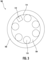
FIG. 3 illustrates a cross-sectional view of the example air quality analysis device in accordance with one or more embodiments of the present disclosure; -
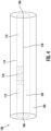
FIG. 4 illustrates another side view of the example air quality analysis device in accordance with one or more embodiments of the present disclosure; -
FIG. 5 illustrates another cross-sectional view of the example air quality analysis device in accordance with one or more embodiments of the present disclosure; -
FIG. 6 illustrates an example user interface of a computing device in accordance with one or more embodiments of the present disclosure; -
FIG. 7 illustrates a flowchart of an example method of performing air quality analysis in accordance with one or more embodiments of the present disclosure; and -
FIG. 8 illustrates a block diagram of an example computer processing device in accordance with one or more embodiments of the present disclosure. - Example embodiments will be described more fully hereinafter with reference to the accompanying drawings, in which some, but not all embodiments of disclosure are shown. Indeed, embodiments of the disclosure may be embodied in many different forms and should not be construed as limited to the embodiments set forth herein; rather, these embodiments are provided so that this disclosure will satisfy applicable legal requirements. Like numbers refer to like elements throughout.
- Example embodiments disclosed herein address technical problems associated with air quality analysis devices and methods of performing air quality analysis. As would be understood by one skilled in the field to which this disclosure pertains, there are numerous example scenarios in which a user may use an air quality analysis device and methods of performing air quality analysis. For example, it may be necessary to use an air quality analysis device to generate air quality data of air flow associated with a continuous positive airway pressure (CPAP) machine that indicates that there is a probably of mold being in the air flow and/or the CPAP machine.
- A CPAP machine, for example, provides a flow of pressurized air that, in some examples, is also heated and humified, to a user's upper airway while the user is sleeping to ensure that the user's upper airway is not obstructed so the user can obtain enough oxygen while sleeping. In some examples, due to the frequent use of CPAP machines (e.g., every night), the humidification of the air flow, the heating of the air flow, and/or infrequent cleaning by a user of the CPAP machine, CPAP machines often develop mold, resulting in the user being exposed to mold when using the CPAP machine. Accordingly, there is a need for devices and methods that can generate air quality data associated with the air flow provided by CPAP machines to users to ensure that the users do not breath in air flow having mold in it.
- Thus, to address these and/or other related issues, an air quality analysis device and a method of performing air quality analysis are disclosed herein. For example, an embodiment in this disclosure, described in greater detail below, includes an air quality analysis device having a housing having a chamber comprising an inlet port. In some embodiments, the inlet port is structured to receive an air flow into the chamber. In some embodiments, the air quality analysis device may include a plurality of sensors disposed within the chamber and configured to generate air quality data associated with the air flow. In some embodiments, the plurality of sensors comprises at least one mold sensor. In some embodiments, the air quality analysis device may include a printed circuit board in communication with the plurality of sensors and configured to transmit the air quality data to a computing device. As such, the air quality of air flow provided by CPAP machines may be analyzed to ensure that a user of the CPAP machine does not breath in air flow provided by the CPAP machine having mold in it.
- With reference to
FIGS. 1-5 , embodiments herein provide for an example airquality analysis device 100. The airquality analysis device 100 may be configured to generate air quality data associated with an air flow. In some embodiments, such as illustrated inFIG. 1 , the airquality analysis device 100 may be configured to generate air quality data associated with air flow provided by a continuous positive pressure machine (CPAP)machine 120. Although referred to herein as performing air quality analysis associated with airflow provided by a CPAP machine, it would be understood by one skilled in the field to which this disclosure pertains that the airquality analysis device 100 may be used to generate air quality data associated with air flow provided by any type of positive airway pressure machine, such as automatic positive airway pressure (APAP) machines, bilevel positive airway pressure (BiPAP) machines, adaptive servo-ventilation (ASV) machines, other mechanical ventilation machines, and/or the like. - In some embodiments, the air
quality analysis device 100 may include ahousing 102. Thehousing 102 may be substantially cubical, substantially rectangular, and/or substantially cylindrical. In some embodiments, thehousing 102 may include achamber 104. Thechamber 104 may be substantially cubical, substantially rectangular, and/or substantially cylindrical. In some embodiments, thechamber 104 may be substantially the same shape as thehousing 102. In some embodiments, thechamber 104 may not be substantially the same shape as thehousing 102. In some embodiments, thehousing 102 and/or thechamber 104 may be comprised of plastic or any other suitable material. In some embodiments, thehousing 102 and/or thechamber 104 may be constructed using injection molding and/or 3D printing. - In some embodiments, the
chamber 104 may have aninlet port 106 and/or anoutlet port 108. In this regard, for example, theinlet port 106 may be configured to receive air flow into thechamber 104 and theoutlet port 108 may be configured to discharge air flow into the chamber 104 (e.g., the air flow moves through thechamber 104 from theinlet port 106 to the outlet port 108). In some embodiments, theinlet port 106 may be structured to receive the air flow into thechamber 104 from ablower 122 of theCPAP machine 120 and theoutlet port 108 may be structured to discharge the air to atube 124 associated with the CPAP machine 120 (e.g., theinlet port 106 may be structured to be attached to theblower 122 of theCPAP machine 120 and theoutlet port 108 may be structured to be attached to thetube 124 associated with the CPAP machine 120). Additionally or alternatively, theinlet port 106 may be structured to receive the air flow into thechamber 104 from thetube 124 of theCPAP machine 120 and theoutlet port 108 may be structured to discharge the air to aface mask 126 associated with the CPAP machine 120 (e.g., theinlet port 106 may be structured to be attached to thetube 124 of theCPAP machine 120 and theoutlet port 108 may be structured to be attached to theface mask 126 associated with the CPAP machine 120). - In some embodiments, the air
quality analysis device 100 may include a plurality ofsensors 110 disposed in thechamber 104. The plurality ofsensors 110 may be disposed in thechamber 104 in any manner that enables the plurality ofsensors 110 to generate air quality data associated with the air flow. Said differently, for example, the plurality ofsensors 110 may be disposed in thechamber 104 in any manner that enables each of the plurality ofsensors 110 to be able to interact with the air flow such that each of the plurality ofsensors 110 can generate air quality data associated with the air flow. For example, such as illustrated inFIGS. 2 and3 , the plurality ofsensors 110 may be disposed on aninterior surface 114 of thechamber 104. As another example, such as illustrated inFIGS. 4 and5 , the plurality ofsensors 110 may be disposed in afirst portion 116 of thechamber 104. That is, the plurality ofsensors 110 may all be disposed in afirst portion 116 of thechamber 104 and none of the plurality ofsensors 110 may be disposed in asecond portion 118 of thechamber 104. - In some embodiments, the plurality of
sensors 110 may be configured to generate air quality data associated with the air flow. In this regard, for example, the plurality ofsensors 110 may be configured to generate air quality data associated with the air flow by generating air quality data indicating a probability of mold in the air flow, generating air quality data indicating that there are particles in the air flow having a particular size, generating air quality data indicating volatile organic compounds in the air flow, generating air quality data indicating a humidity associated with the air flow, and/or generating air quality data indicating a temperature associated with the air flow. In some embodiments, if the plurality ofsensors 110, based on the air quality data generated by the plurality ofsensors 110, determine a probability that mold is present in the air flow, particles of a particular size are present in the air flow, and/or volatile organic compounds are in the air flow. In this regard, for example, the air quality data may indicate that mold, particles of a particular size, and/or volatile organic compounds are present in theCPAP machine 120, thetube 124, and/or theface mask 126. - In some embodiments, the plurality of
sensors 110 may include at least one mold sensor. In this regard, for example, the plurality ofsensors 110 may include at least one mold sensor configured to generate air quality data indicating a probability of mold in the air flow (e.g., is mold present in the air flow). In some embodiments, the at least one mold sensor may include a spectrometer configured to generate air quality data indicating a probability of mold in the air flow. Additionally or alternatively, the at least one mold sensor may be configured to generate air quality data indicating a probability of mold in the air flow based on one or more of humidity associated with the air flow, a temperature associated with the air flow, a particle concentration associated with the air flow, and a cleaning date associated with the air flow. For example, the mold sensor may be configured to generate air quality data that there is a probability mold in the air flow when the humidity associated with the air flow is a above a humidity threshold (e.g., above 95%) and the cleaning date associated with the air flow indicates that it has been a greater amount of time than a cleaning time threshold (e.g., it has been 6 months since theCPAP Machine 120 has been cleaned and the cleaning time threshold is 3 months). In this regard, for example, In some embodiments, based on the generated air quality data, the at least one mold sensor may be configured to determine that the probability mold is present in the air flow is low, medium, or high that mold is present in the air flow. - In some embodiments, the plurality of
sensors 110 may include at least one particulate matter sensor. In this regard, for example, the plurality ofsensors 110 may include at least one particulate matter sensor configured to generate air quality data indicating that there are particles in the air flow (e.g., how many particles in the air flow, concentration of particles in the air flow, size of particles in the air flow, etc.), such as particles having a diameter of less than 2.5 microns and/or 10 microns. In this regard, for example, the plurality ofsensors 110 may include a first particulate matter sensor to generate air quality data indicating that there are particles having a diameter of 2.5 microns or less and/or a second particulate matter sensor to generate air quality data indicating that there are particles having a diameter of 10 microns or less. In some embodiments, the plurality ofsensors 110 may include a particulate matter sensor that is configured to generate air quality data indicating that there are multiple particles of multiple diameters, such as a particulate matter sensor that can generate air quality data indicating that there are particles having a diameter of 2.5 microns or less and/or particles have a diameter of 10 microns or less. - In some embodiments, the plurality of
sensors 110 may include at least one volatile organic compound sensor. In this regard, for example, the plurality ofsensors 110 may include at least one volatile organic compound sensor that configured to generate air quality data indicating volatile organic compounds in the air flow, such as one or more of benzene, ethylene glycol, formaldehyde, acetone, methylene chloride, tetrachloroethylene, toluene, xylene, and/or 1,3-butadiene. In some embodiments, the plurality ofsensors 110 may include volatile organic compound sensors that are each configured to generate air quality data indicating that there are a specific volatile organic compound is in the air flow. For example, the plurality ofsensors 110 may include a first volatile organic compound sensor configured to generate air quality data indicating that there is a first volatile organic compound in the air flow, such as benzene, and a second volatile organic compound sensor configured to generate air quality data indicating that there is a second volatile organic compound, such as acetone. In some embodiments, the plurality ofsensors 110 may include a volatile organic compound sensor that is configured to generate air quality data indicating that there are more than one volatile organic compound in the air flow. - In some embodiments, the plurality of
sensors 110 may include at least one humidity sensor. In this regard, for example, the plurality ofsensors 110 may include at least one humidity sensor that can generate air quality data indicating a humidity associated with the air flow. For example, the at least one humidity sensor may generate air quality data indicating that the air flow is associated with a 90% humidity. In some embodiments, the plurality ofsensors 110 may include at least one temperature sensor. In this regard, for example, the plurality ofsensors 110 may include at least one temperature sensor that can generate air quality data indicating a temperature associated with the air flow. For example, the at least one temperature sensor may generate air quality data indicating that the air flow has a temperature of 90 degrees. - In some embodiments, the air quality data generated by the plurality of
sensors 110 may be obtained and stored in a structured and/or in an unstructured data format. For example, the air quality data may indicate that the probability of mold being in the air flow is low, medium, or high mold is present in the air flow based on the air quality data generated made by the mold sensor. As another example, the air quality data may include a count of the number of times the at least one particulate matter sensor generated air quality data indicating that particles of a particular size are in the air flow (e.g., the at least one particulate matter sensor counted 25 particles with a size of 2.5 microns or less in the air flow). As another example, the air quality data may include an indication of whether or not the at least one volatile organic compound sensor generated air quality data indicating that a specific volatile organic compound is in the air flow (e.g., the at least one volatile organic compound sensor generated air quality data indicating that formaldehyde is in the air flow). As another example, the air quality data may include a temperature and a humidity associated with the air flow as generated by the at least one temperature sensor and/or humidity sensor. - In some embodiments, the air
quality analysis device 100 may include a printed circuit board (PCB) 112. In some embodiments, thePCB 112 may be disposed proximate the plurality ofsensors 110. For example, if the plurality ofsensors 110 is disposed on theinterior surface 114 of thechamber 104, such as illustrated inFIGS. 2 and3 , thePCB 112 may be disposed on theinterior surface 114 of thechamber 104. Additionally or alternatively, if the plurality of sensors is disposed in thefirst portion 116 of thechamber 104, such as illustrated inFIGS. 4 and5 , the PCB may be disposed in thefirst portion 116 of thechamber 104. - In some embodiments, the
PCB 112 may be in electrical communication with the plurality ofsensors 110 and be configured to transmit the air quality data generated by the plurality ofsensors 110 to acomputing device 128. In some embodiments, thePCB 112 may transmit the air quality data generated by the plurality ofsensors 110 to thecomputing device 128 via Wi-Fi and/or Bluetooth. In some embodiments, thePCB 112 may be configured to transmit the air quality data to the computing device in real-time. For example, each time the at least one volatile organic compound sensor generated air quality data indicating that a volatile organic compound is in the air flow, thePCB 112 may transmit generated air quality data to thecomputing device 128. - In some embodiments, the
PCB 112 may be configured to transmit the air quality data to thecomputing device 128 on a pre-determined schedule. For example, thePCB 112 may transmit the air quality data to thecomputing device 128 every 20 seconds. In some embodiments, thePCB 112 may be configured to transmit the air quality data to thecomputing device 128 at the end of an analysis period. For example, thePCB 112 may be configured to identify when air flow has started flowing through thechamber 104 and when air flow has stopped flowing through thechamber 104. In this regard, when thePCB 112 has identified that the air flow has stopped flowing through thechamber 104, thePCB 112 may transmit the air quality data to thecomputing device 128. In some embodiments, thePCB 112 may be configured to transmit the air quality data to thecomputing device 128 upon receiving an instruction to transmit the air quality data from thecomputing device 128. - With reference to
FIG. 6 , in some embodiments, thecomputing device 128 may include auser interface 602. In some embodiments, theuser interface 602 may be provided by a mobile application executing on thecomputing device 128. In some embodiments, theuser interface 602 may include an airquality data component 604 configured to indicate air quality data generated by the plurality ofsensors 110. For example, the airquality data component 604 may indicate that the probability that there is mold in the air flow is low, medium, or high, theCPAP machine 120, thetube 124, and/or theface mask 126 if the at least one mold sensor determines that the probability that there is mold in the air flow is low, medium, or high. As another example, the airquality data component 604 may indicate a count of the number of times the at least one particulate matter sensor generated air quality data indicating particles of a particular size and the size of the particles in the air flow, theCPAP machine 120, thetube 124, and/or theface mask 126 if the at least one particulate matter sensor determines a count of the number of times the at least one particulate matter sensor generated air quality data indicating particles of a particular size and the size of the particles in the air flow. As another example, the airquality data component 604 may indicate that there is an at least one volatile organic compound sensor in the air flow, theCPAP machine 120, thetube 124, and/or theface mask 126 if the at least one volatile organic compound sensor generated air quality data indicating a specific volatile organic compound is in the air flow (e.g., the at least one volatile organic compound sensor generated air quality data indicating formaldehyde is in the air flow). As another example, the airquality data component 604 may indicate a humidity and/or temperature associated with the air flow theCPAP machine 120, thetube 124, and/or theface mask 126 based on air quality data indicating a humidity of the air flow generated by the at least one humidity sensor and/or air quality data indicating a temperature of the air flow generated by the at least one temperature sensor. - In some embodiments, the
user interface 602 may include acleaning component 606 configured to display an instruction indicating that theCPAP machine 120, thetube 124, and/or theface mask 126 should be cleaned. For example, thecleaning component 606 may display an instruction indicating that theCPAP machine 120, thetube 124, and/or theface mask 126 should be cleaned if the probability that mold is present in the air flow, theCPAP machine 120, thetube 124, and/or theface mask 126 is medium or high. As another example, thecleaning component 606 may display an instruction indicating that theCPAP machine 120, thetube 124, and/or theface mask 126 should be cleaned if a count of the number of times the at least one particulate matter sensor generated air quality data indicating particles of a particular size in the air flow theCPAP machine 120, thetube 124, and/or theface mask 126 is above a particle threshold. As another example, thecleaning component 606 may display an instruction indicating that theCPAP machine 120, thetube 124, and/or theface mask 126 should be cleaned if the at least one volatile organic compound sensor generated air quality data indicating a specific volatile organic compound (e.g., the at least one volatile organic compound sensor generated air quality data indicating formaldehyde is in the air flow) is in the air flow. As another example, thecleaning component 606 may display an instruction indicating that theCPAP machine 120, thetube 124, and/or theface mask 126 should be cleaned if a temperature and a humidity and/or temperature associated with the air flow theCPAP machine 120, thetube 124, and/or theface mask 126 if a humidity of the air flow is above a humidity threshold and/or a temperature of the air flow is above a temperature threshold. - Referring now to
FIG. 7 , a flowchart providing anexample method 700 of performing air quality analysis is illustrated. In this regard,FIG. 7 illustrates operations that may be performed by thecomputing device 128 and/or the airquality analysis device 100. - As shown in
block 710, themethod 700 of performing air quality analysis may include receiving air quality data from an air quality analysis device. As described above, the air quality analysis device may include a housing. In some embodiments, the housing may include a chamber. In some embodiments, the housing and/or the chamber may be comprised of plastic or any other suitable material. In some embodiments, the housing and/or the chamber may be constructed using injection molding and/or 3D printing. - In some embodiments, the chamber may have an inlet port and/or an outlet port. In this regard, for example, the inlet port may be configured to receive air flow into the chamber and the outlet port may be configured to discharge air flow into the chamber (e.g., the air flow moves through the chamber from the inlet port to the outlet port). In some embodiments, the inlet port may be structured to receive the air flow into the chamber from a blower of the CPAP machine and the outlet port may be structured to discharge the air to a tube associated with the CPAP machine (e.g., the inlet port may be structured to be attached to the blower of the CPAP machine and the outlet port may be structured to be attached to the tube associated with the CPAP machine). Additionally or alternatively, the inlet port may be structured to receive the air flow into the chamber from the tube of the CPAP machine and the outlet port may be structured to discharge the air to a face mask associated with the CPAP machine (e.g., the inlet port may be structured to be attached to the tube of the CPAP machine and the outlet port may be structured to be attached to the face mask associated with the CPAP machine).
- As described above, in some embodiments, the air quality analysis device may include a plurality of sensors disposed in the chamber. The plurality of sensors may be disposed in the chamber in any manner that enables the plurality of sensors to generate air quality data associated with the air flow. Said differently, for example, the plurality of sensors may be disposed in the chamber in any manner that enables each of the plurality of sensors to be able to interact with the air flow such that each of the plurality of sensors can generate air quality data associated with the air flow. For example, the plurality of sensors may be disposed on an interior surface of the chamber. As another example, the plurality of sensors may be disposed in a first portion of the chamber. That is, the plurality of sensors may all be disposed in a first portion of the chamber and none of the plurality of sensors may be disposed in a second portion of the chamber.
- As described above, in some embodiments, the plurality of sensors may be configured to generate air quality data associated with the air flow. In this regard, for example, the plurality of sensors may be configured to generate air quality data associated with the air flow by generating air quality data indicating that there is a probability of mold in the air flow, generating air quality data indicating particles in the air flow having a particular size, generating air quality data indicating volatile organic compounds in the air flow, generating air quality data indicating a humidity associated with the air flow, and/or generating air quality data indicating a temperature associated with the air flow. In some embodiments, if the plurality of sensors, based on air quality data generated by the plurality of sensors, determine that a probability of mold being in the air flow, particles of a particular size are present in the air flow, and/or volatile organic compounds are in the air flow, it may indicate that mold, particles of a particular size, and/or volatile organic compounds are present in the CPAP machine, the tube, and/or the face mask.
- As described above, in some embodiments, the air quality data generated by the plurality of sensors may be obtained and stored in a structured and/or in an unstructured data format. In some embodiments, the air quality analysis device may include a printed circuit board (PCB). In some embodiments, the PCB may be disposed proximate the plurality of sensors. For example, if the plurality of sensors is disposed on the interior surface of the chamber the PCB may be disposed on the interior surface of the chamber. Additionally or alternatively, if the plurality of sensors is disposed in the first portion of the chamber the PCB may be disposed in the first portion of the chamber.
- As described above, in some embodiments, the PCB may be in electrical communication with the plurality of sensors and be configured to transmit the air quality data generated by the plurality of sensors to a computing device and the computing device may be configured to receive the air quality data from the PCB. In some embodiments, the PCB may transmit the air quality data generated by the plurality of sensors to the computing device via Wi-Fi and/or Bluetooth.
- As shown in
block 720, themethod 700 of performing air quality analysis may include causing a user interface to display an instruction to a user associated with a continuous positive airway pressure machine instructing the user to clean the continuous positive airway pressure machine. - As described above, in some embodiments, the user interface may include a cleaning component configured to display an instruction indicating that the CPAP machine, the tube, and/or the face mask should be cleaned. For example, the cleaning component may display an instruction indicating that the CPAP machine, the tube, and/or the face mask should be cleaned if the probability that mold is present in the air flow is medium or high in the air flow, the CPAP machine, the tube, and/or the face mask. As another example, the cleaning component may display an instruction indicating that the CPAP machine, the tube, and/or the face mask should be cleaned if the air quality data generated by the at least one particulate matter sensor indicates a count of the particles of a particular size in the air flow the CPAP machine, the tube, and/or the face mask is above a particle threshold. As another example, the cleaning component may display an instruction indicating that the CPAP machine, the tube, and/or the face mask should be cleaned if the at least one volatile organic compound sensor generated air quality data indicating a specific volatile organic compound (e.g., the at least one volatile organic compound sensor generated air quality data indicating formaldehyde is in the air flow) in the air flow. As another example, the cleaning component may display an instruction indicating that the CPAP machine, the tube, and/or the face mask should be cleaned if a temperature and a humidity and/or temperature associated with the air flow the CPAP machine, the tube, and/or the face mask if a humidity of the air flow is above a humidity threshold and/or a temperature of the air flow is above a temperature threshold.
- With reference to
FIG 8 , a block diagram of an examplecomputer processing device 800 is illustrated in accordance with some example embodiments. In some embodiments, thePCB 112, thecomputing device 128, and/or other devices may be embodied as one or more computer processing devices, such as thecomputer processing device 800 inFIG. 8 . However, it should be noted that the components, devices, or elements illustrated in and described with respect toFIG. 8 below may not be mandatory and thus one or more may be omitted in certain embodiments. Additionally, some embodiments may include further or different components, devices or elements beyond those illustrated in and described with respect toFIG. 8 . - The
computer processing device 800 may include or otherwise be in communication withprocessing circuitry 802 that is configurable to perform actions in accordance with one or more embodiments disclosed herein. In this regard, theprocessing circuitry 802 may be configured to perform and/or control performance of one or more functionalities of thecomputer processing device 800 in accordance with various embodiments, and thus may provide means for performing functionalities of thecomputer processing device 800 in accordance with various embodiments. Theprocessing circuitry 802 may be configured to perform data processing, application execution and/or other processing and management services according to one or more embodiments. In some embodiments, thecomputer processing device 800 or a portion(s) or component(s) thereof, such as theprocessing circuitry 802, may be embodied as or comprise a chip or chip set. In other words, thecomputer processing device 800 or theprocessing circuitry 802 may comprise one or more physical packages (e.g., chips) including materials, components and/or wires on a structural assembly (e.g., a baseboard). The structural assembly may provide physical strength, conservation of size, and/or limitation of electrical interaction for component circuitry included thereon. Thecomputer processing device 800 or theprocessing circuitry 802 may therefore, in some cases, be configured to implement an embodiment of the disclosure on a single chip or as a single "system on a chip." As such, in some cases, a chip or chipset may constitute means for performing one or more operations for providing the functionalities described herein. - In some embodiments, the
processing circuitry 802 may include aprocessor 806 and, in some embodiments, such as that illustrated inFIG. 8 , may further includememory 804. Theprocessing circuitry 802 may be in communication with or otherwise control auser interface 808 and/or acommunication interface 810. As such, theprocessing circuitry 802 may be embodied as a circuit chip (e.g., an integrated circuit chip) configured (e.g., with hardware, software or a combination of hardware and software) to perform operations described herein. - The
processor 806 may be embodied in a number of different ways. For example, theprocessor 806 may be embodied as various processing means such as one or more of a microprocessor or other processing element, a coprocessor, a controller or various other computing or processing devices including integrated circuits such as, for example, an ASIC (application specific integrated circuit), an FPGA (field programmable gate array), or the like. Although illustrated as a single processor, it will be appreciated that theprocessor 806 may comprise a plurality of processors. The plurality of processors may be in operative communication with each other and may be collectively configured to perform one or more functionalities of thecomputer processing device 800 as described herein. In some embodiments, theprocessor 806 may be configured to execute instructions stored in thememory 804 or otherwise accessible to theprocessor 806. As such, whether configured by hardware or by a combination of hardware and software, theprocessor 806 may represent an entity (e.g., physically embodied in circuitry - in the form of processing circuitry 802) capable of performing operations according to embodiments of the present disclosure while configured accordingly. Thus, for example, when theprocessor 806 is embodied as an ASIC, FPGA or the like, theprocessor 806 may be specifically configured hardware for conducting the operations described herein. Alternatively, as another example, when theprocessor 806 is embodied as an executor of software instructions, the instructions may specifically configure theprocessor 806 to perform one or more operations described herein. - In some embodiments, the
memory 804 may include one or more non-transitory memory devices such as, for example, volatile and/or non-volatile memory that may be either fixed or removable. In this regard, thememory 804 may comprise a non-transitory computer-readable storage medium. It will be appreciated that while thememory 804 is illustrated as a single memory, thememory 804 may comprise a plurality of memories. Thememory 804 may be configured to store information, data, applications, instructions and/or the like for enabling thecomputer processing device 800 to carry out various functions in accordance with one or more embodiments. For example, thememory 804 may be configured to buffer input data for processing by theprocessor 806. Additionally or alternatively, thememory 804 may be configured to store instructions for execution by theprocessor 806. As yet another alternative, thememory 804 may include one or more databases that may store a variety of files, contents or data sets. Among the contents of thememory 804, applications may be stored for execution by theprocessor 806 in order to carry out the functionality associated with each respective application. In some cases, thememory 804 may be in communication with one or more of theprocessor 806,user interface 808, and/orcommunication interface 810 via a bus(es) for passing information among components of thecomputer processing device 800. - The
user interface 808 may be in communication with theprocessing circuitry 802 to receive an indication of a user input at theuser interface 808 and/or to provide an audible, visual, mechanical or other output to the user. As such, theuser interface 808 may include, for example, a keyboard, a mouse, a joystick, a display, a touch screen display, a microphone, a speaker, and/or other input/output mechanisms. As such, theuser interface 808 may, in some embodiments, provide means for a user to access and interact with thePCB 112 and/or thecomputing device 128. - The
communication interface 810 may include one or more interface mechanisms for enabling communication with other devices and/or networks. In some cases, thecommunication interface 810 may be any means such as a device or circuitry embodied in either hardware, or a combination of hardware and software that is configured to receive and/or transmit data from/to a network and/or any other device or module in communication with theprocessing circuitry 802. By way of example, thecommunication interface 810 may be configured to enable thePCB 112 to communicate with thecomputing device 128 and/or computing devices. Accordingly, thecommunication interface 810 may, for example, include an antenna (or multiple antennas) and supporting hardware and/or software for enabling communications with a wireless communication network (e.g., a wireless local area network, cellular network, global positing system network, and/or the like) and/or a communication modem or other hardware/software for supporting communication via cable, digital subscriber line (DSL), universal serial bus (USB), Ethernet or other methods. - Many modifications and other embodiments of the inventions set forth herein will come to mind to one skilled in the art to which these inventions pertain having the benefit of teachings presented in the foregoing descriptions and the associated drawings. Although the figures only show certain components of the apparatus and systems described herein, it is understood that various other components may be used in conjunction with the system. Therefore, it is to be understood that the inventions are not to be limited to the specific embodiments disclosed and that modifications and other embodiments are intended to be included within the scope of the appended claims. Moreover, the steps in the method described above may not necessarily occur in the order depicted in the accompanying diagrams, and in some cases one or more of the steps depicted may occur substantially simultaneously, or additional steps may be involved. Although specific terms are employed herein, they are used in a generic and descriptive sense only and not for purposes of limitation.
- While various embodiments in accordance with the principles disclosed herein have been shown and described above, modifications thereof may be made by one skilled in the art without departing from the spirit and the teachings of the disclosure. The embodiments described herein are representative only and are not intended to be limiting. Many variations, combinations, and modifications are possible and are within the scope of the disclosure. Alternative embodiments that result from combining, integrating, and/or omitting features of the embodiment(s) are also within the scope of the disclosure. Accordingly, the scope of protection is not limited by the description set out above.
- Additionally, the section headings used herein are provided for consistency with the suggestions under 37 C.F.R. 1.77 or to otherwise provide organizational cues. These headings shall not limit or characterize the invention(s) set out in any claims that may issue from this disclosure.
- Use of broader terms such as "comprises," "includes," and "having" should be understood to provide support for narrower terms such as "consisting of," "consisting essentially of," and "comprised substantially of" Use of the terms "optionally," "may," "might," "possibly," and the like with respect to any element of an embodiment means that the element is not required, or alternatively, the element is required, both alternatives being within the scope of the embodiment(s). Also, references to examples are merely provided for illustrative purposes, and are not intended to be exclusive.
Claims (15)
- An air quality analysis device, the air quality analysis device comprising:a housing having a chamber comprising an inlet port, wherein the inlet port is structured to receive an air flow into the chamber;a plurality of sensors disposed within the chamber and configured to generate air quality data associated with the air flow, wherein the plurality of sensors comprises at least one mold sensor; anda printed circuit board in communication with the plurality of sensors and configured to transmit the air quality data to a computing device.
- The air quality analysis device of Claim 1, wherein the plurality of sensors further comprises at least one of a particulate matter sensor, a volatile organic compound sensor, a humidity sensor, or a temperature sensor.
- The air quality analysis device of Claim 2, wherein the particulate matter sensor is configured to generate air quality data indicating that there are particles having a diameter of less than 2.5 microns or 10 microns in the air flow.
- The air quality analysis device of Claim 1, wherein the plurality of sensors further comprises a first volatile organic compound sensor and a second volatile organic compound sensor, wherein the first volatile organic compound sensor is configured to generate air quality data indicating that there is a first volatile organic compound in the air flow and the second volatile organic compound sensor is configured to generate air quality data indicating that there is a second volatile organic compound in the air flow.
- The air quality analysis device of Claim 1, wherein the at least one mold sensor comprises a spectrometer.
- The air quality analysis device of Claim 1, wherein the at least one mold sensor is configured to generate air quality data indicating a probability of mold being in the air flow based at least on a humidity associated with the air flow, a temperature associated with the air flow, a particle concentration associated with the air flow, and a cleaning date associated with the air flow.
- The air quality analysis device of Claim 1, wherein the chamber comprises an outlet port structured to discharge the air flow from the chamber.
- The air quality analysis device of Claim 7, wherein inlet port is structured to receive the air flow into the chamber from a tube associated with a continuous positive airway pressure machine and the outlet port is structured to discharge the air flow from the chamber into a face mask associated with the continuous positive airway pressure machine.
- The air quality analysis device of Claim 7, wherein inlet port is structured to receive the air flow into the chamber from a blower of a continuous positive airway pressure machine and the outlet port is structured to discharge the air flow from the chamber into a tube associated with the continuous positive airway pressure machine.
- The air quality analysis device of Claim 1, wherein the chamber comprises a first portion and a second portion, wherein the plurality of sensors is disposed in the first portion.
- The air quality analysis device of Claim 1, wherein the computing device comprises a user interface configured display an instruction indicating that a user should clean a continuous positive airway pressure machine associated with the user.
- A method of performing an air quality analysis, the method comprising:receiving air quality data from an air quality analysis device, wherein the air quality analysis device comprises:a housing having a chamber comprising an inlet port, wherein the inlet port is structured to receive an air flow into the chamber;a plurality of sensors disposed within the chamber and configured to generate air quality data associated with the air flow, wherein the plurality of sensors comprises at least one mold sensor; anda printed circuit board in communication with the plurality of sensors and configured to transmit the air quality data to a computing device; andcausing a user interface to display an instruction to a user associated with a continuous positive airway pressure machine instructing the user to clean the continuous positive airway pressure machine.
- The method of Claim 12, wherein the plurality of sensors further comprises at least one of a particulate matter sensor, a volatile organic compound sensor, a humidity sensor, or a temperature sensor.
- The method of Claim 12, wherein the at least one mold sensor comprises a spectrometer.
- The method of Claim 12, wherein the at least one mold sensor is configured to generate air quality data indicating a probability of mold being in the air flow based at least on a humidity associated with the air flow, a temperature associated with the air flow, a particle concentration associated with the air flow, and a cleaning date associated with the air flow.
Applications Claiming Priority (1)
| Application Number | Priority Date | Filing Date | Title |
|---|---|---|---|
| US18/194,918 US20240325671A1 (en) | 2023-04-03 | 2023-04-03 | Air quality analysis device |
Publications (1)
| Publication Number | Publication Date |
|---|---|
| EP4443157A1 true EP4443157A1 (en) | 2024-10-09 |
Family
ID=90057576
Family Applications (1)
| Application Number | Title | Priority Date | Filing Date |
|---|---|---|---|
| EP24159481.1A Pending EP4443157A1 (en) | 2023-04-03 | 2024-02-23 | Air quality analysis device |
Country Status (6)
| Country | Link |
|---|---|
| US (1) | US20240325671A1 (en) |
| EP (1) | EP4443157A1 (en) |
| JP (1) | JP7850191B2 (en) |
| CN (1) | CN118777516A (en) |
| AU (2) | AU2024201235B2 (en) |
| CA (1) | CA3231444A1 (en) |
Families Citing this family (2)
| Publication number | Priority date | Publication date | Assignee | Title |
|---|---|---|---|---|
| US12203668B2 (en) | 2022-08-29 | 2025-01-21 | Honeywell International Inc. | Air quality monitoring device and associated method of manufacturing |
| JP2026043876A (en) | 2024-08-29 | 2026-03-12 | 京セラドキュメントソリューションズ株式会社 | Image forming apparatus |
Citations (5)
| Publication number | Priority date | Publication date | Assignee | Title |
|---|---|---|---|---|
| WO2013112287A1 (en) * | 2012-01-09 | 2013-08-01 | David Martin | Networked air quality monitoring |
| KR20180028336A (en) * | 2016-09-08 | 2018-03-16 | 재단법인 다차원 스마트 아이티 융합시스템 연구단 | Apparatus and method for monitoring indoor air quality for vehicle |
| WO2021233957A1 (en) * | 2020-05-18 | 2021-11-25 | Ambisense Ltd. | Air quality monitoring device and system |
| US20210369995A1 (en) * | 2020-05-27 | 2021-12-02 | GE Precision Healthcare LLC | Methods and systems for a medical gas quality monitor |
| WO2022043664A2 (en) * | 2020-08-24 | 2022-03-03 | Flutterlab Ltd | Indoor air quality monitor |
Family Cites Families (11)
| Publication number | Priority date | Publication date | Assignee | Title |
|---|---|---|---|---|
| US6266995B1 (en) * | 1999-05-20 | 2001-07-31 | Respiratory Management Services, Inc. | Portable medical gas system tester |
| US9615773B1 (en) * | 2008-08-13 | 2017-04-11 | Cleveland Medical Devices Inc. | Method and device for sleep analysis and therapy |
| WO2011104770A1 (en) * | 2010-02-26 | 2011-09-01 | Sharp Kabushiki Kaisha | Detection apparatus and method for detecting airborne biological particles |
| DE102014215735A1 (en) * | 2014-08-08 | 2016-02-11 | Robert Bosch Gmbh | Method for operating a room ventilation system, sensor and room ventilation system |
| US10467880B2 (en) * | 2016-09-16 | 2019-11-05 | Nypro Inc. | Apparatus, system and method for a portable personal air quality monitor |
| CN113864958B (en) * | 2016-12-06 | 2023-09-19 | 斐乐公司 | Air purifier with intelligent sensor and air flow |
| US11726022B2 (en) * | 2018-12-31 | 2023-08-15 | Robert Bosch Gmbh | Device for detecting mold |
| JP7461374B2 (en) * | 2019-04-22 | 2024-04-03 | パリ ファーマ ゲーエムベーハー | Nebulizer monitoring devices, systems, and methods |
| US20210372637A1 (en) * | 2020-06-02 | 2021-12-02 | Virender K. Sharma | Methods and Systems for Air Management to Reduce or Block Exposure to Airborne Pathogens |
| US12203668B2 (en) * | 2022-08-29 | 2025-01-21 | Honeywell International Inc. | Air quality monitoring device and associated method of manufacturing |
| US20240278044A1 (en) * | 2023-02-17 | 2024-08-22 | Honeywell International Inc. | Air quality monitoring device and associated method of monitoring air quality |
-
2023
- 2023-04-03 US US18/194,918 patent/US20240325671A1/en active Pending
-
2024
- 2024-02-23 AU AU2024201235A patent/AU2024201235B2/en active Active
- 2024-02-23 EP EP24159481.1A patent/EP4443157A1/en active Pending
- 2024-03-08 CA CA3231444A patent/CA3231444A1/en active Pending
- 2024-03-11 JP JP2024036690A patent/JP7850191B2/en active Active
- 2024-03-12 CN CN202410281139.1A patent/CN118777516A/en active Pending
-
2026
- 2026-01-30 AU AU2026200714A patent/AU2026200714A1/en active Pending
Patent Citations (5)
| Publication number | Priority date | Publication date | Assignee | Title |
|---|---|---|---|---|
| WO2013112287A1 (en) * | 2012-01-09 | 2013-08-01 | David Martin | Networked air quality monitoring |
| KR20180028336A (en) * | 2016-09-08 | 2018-03-16 | 재단법인 다차원 스마트 아이티 융합시스템 연구단 | Apparatus and method for monitoring indoor air quality for vehicle |
| WO2021233957A1 (en) * | 2020-05-18 | 2021-11-25 | Ambisense Ltd. | Air quality monitoring device and system |
| US20210369995A1 (en) * | 2020-05-27 | 2021-12-02 | GE Precision Healthcare LLC | Methods and systems for a medical gas quality monitor |
| WO2022043664A2 (en) * | 2020-08-24 | 2022-03-03 | Flutterlab Ltd | Indoor air quality monitor |
Also Published As
| Publication number | Publication date |
|---|---|
| AU2024201235A1 (en) | 2024-10-17 |
| AU2024201235B2 (en) | 2025-10-30 |
| CN118777516A (en) | 2024-10-15 |
| AU2026200714A1 (en) | 2026-02-19 |
| CA3231444A1 (en) | 2025-07-08 |
| JP7850191B2 (en) | 2026-04-22 |
| JP2024147505A (en) | 2024-10-16 |
| US20240325671A1 (en) | 2024-10-03 |
Similar Documents
| Publication | Publication Date | Title |
|---|---|---|
| AU2026200714A1 (en) | Air quality analysis device | |
| EP4332568A1 (en) | An air quality monitoring device and associated method of manufacturing | |
| US9908072B2 (en) | System and method for replacing air filters | |
| EP3249536A1 (en) | Virtual intelligent platform management interface (ipmi) satellite controller and method | |
| CN113676606B (en) | Shutdown method and apparatus | |
| CN118518819A (en) | Air quality monitoring device and associated method for monitoring air quality | |
| CN101644918B (en) | Administration method and system for message of an electronic apparatus | |
| CN109753641A (en) | A kind of method, apparatus, electronic equipment and storage medium for changing object's position | |
| CN114712740A (en) | Powered Air Purifying Respirator (PAPR) with eccentric venturi air flow rate determination | |
| CN108804177A (en) | Update method, apparatus, computer equipment and the storage medium of interface view | |
| CN108647936A (en) | Commission distribution method, device, computer equipment and storage medium | |
| CN106358220B (en) | Method, device and system for detecting abnormal contact information | |
| CN110720101B (en) | Validate structured data | |
| CN107798036A (en) | A kind of method of counting and counter | |
| CN112261072B (en) | A service calling method, device, equipment and storage medium | |
| CN108874674A (en) | page debugging method and device | |
| CN113590183A (en) | Application gray scale distribution method and device, electronic equipment and storage medium | |
| EP4364771B1 (en) | Sensing and secretion bypass apparatuses and associated methods | |
| CN110597647A (en) | Message interception method and device, electronic equipment and storage medium | |
| Kanestad et al. | Monitoring Air Quality in Ångström Cleanroom Laboratory | |
| CN110960854B (en) | Image mobile display method and device, electronic equipment and storage medium | |
| CN106909646A (en) | SD card clears up the method and device of invalid data after changing | |
| CN107248204A (en) | Attendance recording method and system based on positioning | |
| CN107850883B (en) | System processing method and numerical control system | |
| JP2026007662A (en) | Component mounting control device, component mounting control method, component mounting control program, and recording medium |
Legal Events
| Date | Code | Title | Description |
|---|---|---|---|
| PUAI | Public reference made under article 153(3) epc to a published international application that has entered the european phase |
Free format text: ORIGINAL CODE: 0009012 |
|
| STAA | Information on the status of an ep patent application or granted ep patent |
Free format text: STATUS: REQUEST FOR EXAMINATION WAS MADE |
|
| 17P | Request for examination filed |
Effective date: 20240223 |
|
| AK | Designated contracting states |
Kind code of ref document: A1 Designated state(s): AL AT BE BG CH CY CZ DE DK EE ES FI FR GB GR HR HU IE IS IT LI LT LU LV MC ME MK MT NL NO PL PT RO RS SE SI SK SM TR |
|
| STAA | Information on the status of an ep patent application or granted ep patent |
Free format text: STATUS: EXAMINATION IS IN PROGRESS |
|
| 17Q | First examination report despatched |
Effective date: 20250416 |
|
| GRAP | Despatch of communication of intention to grant a patent |
Free format text: ORIGINAL CODE: EPIDOSNIGR1 |
|
| STAA | Information on the status of an ep patent application or granted ep patent |
Free format text: STATUS: GRANT OF PATENT IS INTENDED |