EP4443156A1 - Method for quantifying gas generated from coal, method for estimating amount of gas generated during coal carbonization, and method for manufacturing coke - Google Patents
Method for quantifying gas generated from coal, method for estimating amount of gas generated during coal carbonization, and method for manufacturing coke Download PDFInfo
- Publication number
- EP4443156A1 EP4443156A1 EP22924958.6A EP22924958A EP4443156A1 EP 4443156 A1 EP4443156 A1 EP 4443156A1 EP 22924958 A EP22924958 A EP 22924958A EP 4443156 A1 EP4443156 A1 EP 4443156A1
- Authority
- EP
- European Patent Office
- Prior art keywords
- gas
- coal
- separation column
- sulfur
- gas generated
- Prior art date
- Legal status (The legal status is an assumption and is not a legal conclusion. Google has not performed a legal analysis and makes no representation as to the accuracy of the status listed.)
- Pending
Links
Images


Classifications
-
- G—PHYSICS
- G01—MEASURING; TESTING
- G01N—INVESTIGATING OR ANALYSING MATERIALS BY DETERMINING THEIR CHEMICAL OR PHYSICAL PROPERTIES
- G01N27/00—Investigating or analysing materials by the use of electric, electrochemical, or magnetic means
- G01N27/62—Investigating or analysing materials by the use of electric, electrochemical, or magnetic means by investigating the ionisation of gases, e.g. aerosols; by investigating electric discharges, e.g. emission of cathode
-
- C—CHEMISTRY; METALLURGY
- C10—PETROLEUM, GAS OR COKE INDUSTRIES; TECHNICAL GASES CONTAINING CARBON MONOXIDE; FUELS; LUBRICANTS; PEAT
- C10B—DESTRUCTIVE DISTILLATION OF CARBONACEOUS MATERIALS FOR PRODUCTION OF GAS, COKE, TAR, OR SIMILAR MATERIALS
- C10B57/00—Other carbonising or coking processes; Features of destructive distillation processes in general
- C10B57/04—Other carbonising or coking processes; Features of destructive distillation processes in general using charges of special composition
-
- G—PHYSICS
- G01—MEASURING; TESTING
- G01N—INVESTIGATING OR ANALYSING MATERIALS BY DETERMINING THEIR CHEMICAL OR PHYSICAL PROPERTIES
- G01N25/00—Investigating or analyzing materials by the use of thermal means
- G01N25/20—Investigating or analyzing materials by the use of thermal means by investigating the development of heat, i.e. calorimetry, e.g. by measuring specific heat, by measuring thermal conductivity
- G01N25/22—Investigating or analyzing materials by the use of thermal means by investigating the development of heat, i.e. calorimetry, e.g. by measuring specific heat, by measuring thermal conductivity on combustion or catalytic oxidation, e.g. of components of gas mixtures
- G01N25/28—Investigating or analyzing materials by the use of thermal means by investigating the development of heat, i.e. calorimetry, e.g. by measuring specific heat, by measuring thermal conductivity on combustion or catalytic oxidation, e.g. of components of gas mixtures the rise in temperature of the gases resulting from combustion being measured directly
- G01N25/38—Investigating or analyzing materials by the use of thermal means by investigating the development of heat, i.e. calorimetry, e.g. by measuring specific heat, by measuring thermal conductivity on combustion or catalytic oxidation, e.g. of components of gas mixtures the rise in temperature of the gases resulting from combustion being measured directly using the melting or combustion of a solid
- G01N25/385—Investigating or analyzing materials by the use of thermal means by investigating the development of heat, i.e. calorimetry, e.g. by measuring specific heat, by measuring thermal conductivity on combustion or catalytic oxidation, e.g. of components of gas mixtures the rise in temperature of the gases resulting from combustion being measured directly using the melting or combustion of a solid for investigating the composition of gas mixtures
-
- G—PHYSICS
- G01—MEASURING; TESTING
- G01N—INVESTIGATING OR ANALYSING MATERIALS BY DETERMINING THEIR CHEMICAL OR PHYSICAL PROPERTIES
- G01N30/00—Investigating or analysing materials by separation into components using adsorption, absorption or similar phenomena or using ion-exchange, e.g. chromatography or field flow fractionation
- G01N30/02—Column chromatography
- G01N30/04—Preparation or injection of sample to be analysed
- G01N30/06—Preparation
-
- G—PHYSICS
- G01—MEASURING; TESTING
- G01N—INVESTIGATING OR ANALYSING MATERIALS BY DETERMINING THEIR CHEMICAL OR PHYSICAL PROPERTIES
- G01N30/00—Investigating or analysing materials by separation into components using adsorption, absorption or similar phenomena or using ion-exchange, e.g. chromatography or field flow fractionation
- G01N30/02—Column chromatography
- G01N30/04—Preparation or injection of sample to be analysed
- G01N30/06—Preparation
- G01N30/08—Preparation using an enricher
-
- G—PHYSICS
- G01—MEASURING; TESTING
- G01N—INVESTIGATING OR ANALYSING MATERIALS BY DETERMINING THEIR CHEMICAL OR PHYSICAL PROPERTIES
- G01N30/00—Investigating or analysing materials by separation into components using adsorption, absorption or similar phenomena or using ion-exchange, e.g. chromatography or field flow fractionation
- G01N30/02—Column chromatography
- G01N30/50—Conditioning of the sorbent material or stationary liquid
- G01N30/52—Physical parameters
- G01N30/54—Temperature
-
- G—PHYSICS
- G01—MEASURING; TESTING
- G01N—INVESTIGATING OR ANALYSING MATERIALS BY DETERMINING THEIR CHEMICAL OR PHYSICAL PROPERTIES
- G01N30/00—Investigating or analysing materials by separation into components using adsorption, absorption or similar phenomena or using ion-exchange, e.g. chromatography or field flow fractionation
- G01N30/02—Column chromatography
- G01N30/88—Integrated analysis systems specially adapted therefor, not covered by a single one of the groups G01N30/04 - G01N30/86
-
- G—PHYSICS
- G01—MEASURING; TESTING
- G01N—INVESTIGATING OR ANALYSING MATERIALS BY DETERMINING THEIR CHEMICAL OR PHYSICAL PROPERTIES
- G01N33/00—Investigating or analysing materials by specific methods not covered by groups G01N1/00 - G01N31/00
- G01N33/22—Fuels; Explosives
- G01N33/222—Solid fuels, e.g. coal
-
- G—PHYSICS
- G01—MEASURING; TESTING
- G01N—INVESTIGATING OR ANALYSING MATERIALS BY DETERMINING THEIR CHEMICAL OR PHYSICAL PROPERTIES
- G01N30/00—Investigating or analysing materials by separation into components using adsorption, absorption or similar phenomena or using ion-exchange, e.g. chromatography or field flow fractionation
- G01N30/02—Column chromatography
- G01N30/88—Integrated analysis systems specially adapted therefor, not covered by a single one of the groups G01N30/04 - G01N30/86
- G01N2030/8809—Integrated analysis systems specially adapted therefor, not covered by a single one of the groups G01N30/04 - G01N30/86 analysis specially adapted for the sample
- G01N2030/884—Integrated analysis systems specially adapted therefor, not covered by a single one of the groups G01N30/04 - G01N30/86 analysis specially adapted for the sample organic compounds
-
- G—PHYSICS
- G01—MEASURING; TESTING
- G01N—INVESTIGATING OR ANALYSING MATERIALS BY DETERMINING THEIR CHEMICAL OR PHYSICAL PROPERTIES
- G01N30/00—Investigating or analysing materials by separation into components using adsorption, absorption or similar phenomena or using ion-exchange, e.g. chromatography or field flow fractionation
- G01N30/02—Column chromatography
- G01N30/88—Integrated analysis systems specially adapted therefor, not covered by a single one of the groups G01N30/04 - G01N30/86
- G01N2030/8809—Integrated analysis systems specially adapted therefor, not covered by a single one of the groups G01N30/04 - G01N30/86 analysis specially adapted for the sample
- G01N2030/884—Integrated analysis systems specially adapted therefor, not covered by a single one of the groups G01N30/04 - G01N30/86 analysis specially adapted for the sample organic compounds
- G01N2030/8854—Integrated analysis systems specially adapted therefor, not covered by a single one of the groups G01N30/04 - G01N30/86 analysis specially adapted for the sample organic compounds involving hydrocarbons
-
- G—PHYSICS
- G01—MEASURING; TESTING
- G01N—INVESTIGATING OR ANALYSING MATERIALS BY DETERMINING THEIR CHEMICAL OR PHYSICAL PROPERTIES
- G01N30/00—Investigating or analysing materials by separation into components using adsorption, absorption or similar phenomena or using ion-exchange, e.g. chromatography or field flow fractionation
- G01N30/02—Column chromatography
- G01N30/62—Detectors specially adapted therefor
- G01N30/72—Mass spectrometers
-
- G—PHYSICS
- G01—MEASURING; TESTING
- G01N—INVESTIGATING OR ANALYSING MATERIALS BY DETERMINING THEIR CHEMICAL OR PHYSICAL PROPERTIES
- G01N33/00—Investigating or analysing materials by specific methods not covered by groups G01N1/00 - G01N31/00
- G01N33/0004—Gaseous mixtures, e.g. polluted air
- G01N33/0009—General constructional details of gas analysers, e.g. portable test equipment
- G01N33/0011—Sample conditioning
- G01N33/0019—Sample conditioning by preconcentration
-
- G—PHYSICS
- G01—MEASURING; TESTING
- G01N—INVESTIGATING OR ANALYSING MATERIALS BY DETERMINING THEIR CHEMICAL OR PHYSICAL PROPERTIES
- G01N33/00—Investigating or analysing materials by specific methods not covered by groups G01N1/00 - G01N31/00
- G01N33/0004—Gaseous mixtures, e.g. polluted air
- G01N33/0009—General constructional details of gas analysers, e.g. portable test equipment
- G01N33/0027—General constructional details of gas analysers, e.g. portable test equipment concerning the detector
- G01N33/0036—General constructional details of gas analysers, e.g. portable test equipment concerning the detector specially adapted to detect a particular component
- G01N33/0042—SO2 or SO3
-
- G—PHYSICS
- G01—MEASURING; TESTING
- G01N—INVESTIGATING OR ANALYSING MATERIALS BY DETERMINING THEIR CHEMICAL OR PHYSICAL PROPERTIES
- G01N33/00—Investigating or analysing materials by specific methods not covered by groups G01N1/00 - G01N31/00
- G01N33/0004—Gaseous mixtures, e.g. polluted air
- G01N33/0009—General constructional details of gas analysers, e.g. portable test equipment
- G01N33/0027—General constructional details of gas analysers, e.g. portable test equipment concerning the detector
- G01N33/0036—General constructional details of gas analysers, e.g. portable test equipment concerning the detector specially adapted to detect a particular component
- G01N33/0044—Sulphides, e.g. H2S
Definitions
- the present invention relates to a method for quantifying gas generated from coal, a method for estimating an amount of gas generated during coal carbonization, and a method for manufacturing coke.
- Coal is used as an important fossil fuel even in modern times because of the length of the reserve-to-production ratio, the low price, and the like of the coal. Coal is mainly used as a raw material of coke used for ironmaking and as a fuel for thermal power plants, and the amount of consumption is continuously increasing.
- a sulfur-based gas derived from sulfur (S) contained as an impurity of coal is not only highly toxic, but also said to contribute to acid rain and a greenhouse effect. Therefore, the sulfur-based gas is required to be strictly controlled, for example, a regulation value is provided.
- Total-S total sulfur concentration
- low-sulfur coal is produced only in some limited regions such as Australia, leading to concentration on a specific brand, which may cause a risk that stable procurement becomes difficult due to the influences of weather-induced troubles in a production area, supply and demand trends in foreign countries, and the like.
- the generation temperature (generation temperature range) and the generation amount of sulfur-based gas generated during heating of coal depend on the existence form of sulfur in the coal.
- Sulfur in coal exists in various forms such as inorganic sulfur and organic sulfur, and the ratio thereof also varies depending on the brand of coal.
- Examples of the inorganic sulfur include two kinds, i.e., sulfate sulfur and pyrite sulfur.
- organic sulfur examples include thiophene, sulfide, thiol, and sulfonic acid.
- Patent Literature 1 discloses a technique of "raising a temperature from room temperature to 1000°C to heat coal in an inert gas, continuously monitoring and measuring sulfur-containing gas generated by thermal decomposition of a sulfur compound, thereby quantifying sulfur in the coal according to its existence form" ([Claim 1]).
- the gas is monitored using, for example, "mass spectrometry" ([0033]).
- Patent Literature 1 JP 2009-257920 A
- the present invention has been made in view of the above points, and an object of the present invention is to quantify gas generated during heating of coal (particularly, sulfur-based gas) with high accuracy.
- the present inventors have conducted intensive studies, and as a result, have found that employing the configuration described below enables the achievement of the above-mentioned object, thereby completing the present invention.
- the present invention provides the following [1] to [6].
- gas generated during heating of coal can be quantified with high accuracy.
- a method for quantifying gas generated from coal according to the present embodiment includes: a gas collection step of collecting gas generated during heating of coal; a gas introduction step of introducing the gas collected in the gas collection step into a separation column of a gas chromatograph; a gas capturing step of capturing the gas introduced into the separation column by cooling the separation column; a gas releasing step of releasing the gas captured in the gas capturing step by deactivating the cooling of the separation column; and an analysis step of analyzing and quantifying the gas released in the gas releasing step by a mass spectrometry unit.
- FIG. 1 is a schematic view illustrating an apparatus 1 used for quantification of gas generated from coal.
- the apparatus 1 includes a chamber 2.
- a separation column 3 of a gas chromatograph, a heating unit 4 heating the separation column 3, and a cooling unit 5 cooling at least a part, in a length direction, of the separation column 3 are provided inside the chamber 2.
- the apparatus 1 further includes a gas injection unit 6 injecting gas into the separation column 3, and a mass spectrometry unit 7 separating and specifying a gas component contained in the gas introduced from the separation column 3 according to a mass-to-charge ratio.
- the heating method of the heating unit 4 is not particularly limited as long as the temperature can be controlled when the separation column 3 is heated, and examples thereof include a heating furnace method using a resistance heater and a high-frequency induction heating method.
- the cooling method of the cooling unit 5 is not particularly limited as long as at least a part of the separation column 3 can be cooled and controlled to an arbitrary temperature, and examples thereof include conventionally known methods such as a Peltier cooling method and a liquid nitrogen cooling method.
- the cooling range of the cooling unit 5 is not particularly limited, but it is preferable that at least a range of a length of about 10 mm in the separation column 3 can be cooled.
- the cooling unit 5 is a cryotrap.
- the cryotrap is a facility that is disposed in the middle of the separation column 3 and blows nitrogen gas cooled with liquid nitrogen to the separation column 3 from the outside.
- the type and polarity of the separation column 3 may be freely selected.
- the apparatus 1 may further include a pyrolysis furnace 8. Gas is generated from coal by heating the coal using the pyrolysis furnace 8.
- the pyrolysis furnace 8 may be any furnace as long as it has heating capability corresponding to the heating temperature of the coal to be charged into the pyrolysis furnace 8.
- the heating method of the pyrolysis furnace 8 a conventionally known method can be adopted, and examples thereof include a filament type in which heating is performed by a filament, an induction heating type in which a sample foil made of alloy is heated by a high-frequency magnetic field, and a heating furnace type.
- the gas collection step is a step of collecting gas generated during heating of coal.
- coal is charged into the pyrolysis furnace 8 and heated. In this way, gas generated from the coal heated inside the pyrolysis furnace 8 is collected.
- the atmosphere in the furnace of the pyrolysis furnace 8 is preferably an inert gas atmosphere in order to avoid superposition of peaks in the mass spectrometry unit 7 in the case of simulating the atmosphere during coal carbonization in a coke oven.
- the inert gas is preferably helium (He), and may be nitrogen (N 2 ) or the like.
- Coal to be charged into the pyrolysis furnace 8 is preferably pulverized to a certain grain size or less in order to prevent temperature unevenness during heating.
- the grain size of the coal is preferably 250 um or less and more preferably 125 um or less.
- the amount of coal corresponding to the volume of the pyrolysis furnace 8 is charged into the pyrolysis furnace 8.
- the amount of coal to be charged into the pyrolysis furnace 8 is preferably about 70 to 80% of the volume of the pyrolysis furnace 8.
- the gas generated during heating of coal contains hydrogen and hydrocarbons (C m H n ) having various molecular weights.
- hydrocarbons C m H n
- low-molecular-weight hydrocarbons include methane (CH 4 ), ethane (C 2 H 6 ), and ethylene (C 2 H 4 ).
- high-molecular-weight hydrocarbons include n-hexane (C 6 H 14 ) and n-decane (C 10 H 22 ), and m > 10 may be satisfied.
- the gas generated during heating of coal further contains a sulfur-based gas.
- the sulfur-based gas contains, for example, a gas component such as hydrogen sulfide (H 2 S), carbonyl sulfide (COS), sulfur dioxide (SO 2 ), carbon disulfide (CS 2 ), or thiophene (C 4 H 4 S).
- gas generated during heating of coal gas generated at a specific heating temperature A or a heating temperature range B may be quantified.
- preliminary heating step of heating coal at a temperature (preliminary heating temperature) lower than the heating temperature A or a lower limit temperature of the heating temperature range B and discharging the generated gas.
- the preliminary heating temperature may be set in consideration of a control range of the temperature inside the pyrolysis furnace 8. For example, when the control range is smaller than 5°C, the preliminary heating temperature is set to be lower than the heating temperature A or the lower limit of the heating temperature range B by 5°C.
- the time for heating coal at the preliminary heating temperature may be any period of time as long as the time is long enough for gas to be no longer generated from the coal by heating at the preliminary heating temperature, and is, for example, 10 minutes or more and preferably 15 minutes or more.
- a discharge path of the gas generated in the preliminary heating step is not particularly limited.
- the gas may be discharged from a split path (not illustrated), or may be allowed to pass through the separation column 3 of the gas chromatograph and discharged.
- the coal is heated in the pyrolysis furnace 8 set at the heating temperature A for a certain period of time to generate gas.
- the heating time is preferably 10 minutes or more and more preferably 15 minutes or more.
- the temperature inside the pyrolysis furnace 8 is raised from the lower limit temperature to the upper limit temperature of the heating temperature range B to generate gas from the coal.
- the temperature rise rate is preferably 10°C/min or less and more preferably 5°C/min or less.
- a step of heating at an upper limit temperature may be added.
- the gas collected in the gas collection step is introduced into the separation column 3 of the gas chromatograph from the gas injection unit 6 by using a carrier gas.
- the gas introduced into the separation column 3 flows together with the carrier gas from one end (the end on the gas injection unit 6 side) toward the other end (the end on the mass spectrometry unit 7 side) of the separation column 3.
- the carrier gas is preferably an inert gas and more preferably a He gas having less influence in the mass spectrometry unit 7.
- the flow rate and the split ratio of the carrier gas are not particularly limited, and may be appropriately adjusted according to the analysis sensitivity of the mass spectrometry unit 7 or the like.
- the cooling unit 5 (for example, a cryotrap) is operated to cool at least a part, in the length direction, of the separation column 3 to a certain cooling temperature.
- cooling target portion the portion of the separation column 3 cooled by the cooling unit 5
- non-cooling target portion the portion of the separation column 3 that is not the cooling target portion
- the gas introduced into the separation column 3 is solidified in the cooling target portion of the separation column 3 by the operation of the cooling unit 5, and is captured inside the separation column 3.
- gas to be introduced into the separation column 3 is a sulfur-based gas
- the cooling temperature of the separation column 3 is set to a temperature lower than - 60°C. As a result, while the cooling unit 5 is operating, all the gas components having boiling points of -60°C or higher are captured in the separation column 3.
- gas components other than the sulfur-based gas among the gas components contained in the gas generated during heating of coal include hydrogen (boiling point: -252.6°C); low-molecular-weight hydrocarbons such as methane (boiling point: -162°C), ethylene (boiling point: - 103.7°C), and ethane (boiling point: -89°C); and high-molecular-weight hydrocarbons such as n-hexane (boiling point: 69°C) and n-decane (boiling point: 174°C).
- hydrogen hydrogen
- low-molecular-weight hydrocarbons such as methane (boiling point: -162°C), ethylene (boiling point: - 103.7°C), and ethane (boiling point: -89°C)
- high-molecular-weight hydrocarbons such as n-hexane (boiling point: 69°C) and n
- a gas component (hydrogen, a low-molecular-weight hydrocarbon, or the like) having a boiling point lower than the cooling temperature of the separation column 3 passes through the separation column 3 without being captured by the separation column 3.
- the gas components (a high-molecular-weight hydrocarbon and the like) having a boiling point equal to or higher than the cooling temperature of the separation column 3 are all captured in the separation column 3 together with the sulfur-based gas.
- the time for cooling the cooling target portion of the separation column 3 is not particularly limited, and is, for example, about 30 seconds to 1 minute.
- the temperature inside the chamber 2 (that is, the temperature of the non-cooling target portion of the separation column 3) is preferably 100°C or lower, more preferably 80°C or lower, and still more preferably 50°C or lower.
- the lower limit is not particularly limited, and is, for example, room temperature (for example, 25°C).
- the temperature control inside the chamber 2 is performed by operating the heating unit 4.
- the temperature gradient between the cooling target portion and the non-cooling target portion of the separation column 3 is gentle during the operation of the cooling unit 5.
- the influence range of the cooling unit 5 that is, the cooling target portion of the separation column 3) is widened, and the analysis error in the mass spectrometry unit 7 can be reduced in the analysis step described below.
- the temperature inside the chamber 2 is preferably in the above range for the reason described below.
- the captured gas is released by deactivating the cooling of the separation column 3.
- the cooling is deactivated by turning off the operation of the cooling unit 5 (for example, a cryotrap).
- the cooling unit 5 for example, a cryotrap
- the temperature of the cooling target portion of the separation column 3 rises, and the solidified gas component volatilizes.
- the gas components are volatilized in order from a gas component having a lower boiling point, move forward inside the separation column 3, and are introduced into the mass spectrometry unit 7 with a time difference.
- the influence of the separation capacity due to the boiling point difference is larger than that of the separation capacity due to the column polarity.
- the gas components reach the mass spectrometry unit 7 in ascending order of boiling point. Therefore, into the mass spectrometry unit 7, a low-molecular-weight hydrocarbon (hydrocarbon-based gas) is first introduced, then a sulfur-based gas is volatilized and introduced, and a high-molecular-weight hydrocarbon (hydrocarbon-based gas) is finally introduced.
- a low-molecular-weight hydrocarbon hydrocarbon-based gas
- sulfur-based gas is volatilized and introduced
- a high-molecular-weight hydrocarbon hydrocarbon-based gas
- a low-molecular-weight hydrocarbon-based gas such as methane, ethane, or ethylene has a smaller mass-to-charge ratio (m/z) than the sulfur-based gas. Therefore, a peak superposed with the sulfur-based gas does not occur.
- a high-molecular-weight hydrocarbon-based gas generates fragment ions having the same mass-to-charge ratio (m/z) as that of the sulfur-based gas when ionized by the mass spectrometry unit 7. Therefore, a peak superposed with the sulfur-based gas occurs, and the peak of the sulfur-based gas cannot be separated with high accuracy.
- the high-molecular-weight hydrocarbon-based gas is introduced into the mass spectrometry unit 7 after the sulfur-based gas. Therefore, the sulfur-based gas can be analyzed by the mass spectrometry unit 7 while avoiding superposition of peaks caused by the high-molecular-weight hydrocarbon-based gas containing no sulfur. That is, the sulfur-based gas generated during heating of coal can be quantified with high accuracy.
- the rate of temperature rise of the cooling target portion of the separation column 3 may become too high after the deactivation of the cooling.
- the temperature inside the chamber 2 is preferably in the above range. That is, the temperature inside the chamber 2 is preferably 100°C or lower, more preferably 80°C or lower, and still more preferably 50°C or lower.
- the rate at which the cooling target portion of the separation column 3 whose cooling has been deactivated rises in temperature can be made slow, and as a result, the sulfur-based gas having a lower boiling point volatilizes before the high-molecular-weight hydrocarbon-based gas that affects the analysis of the sulfur-based gas, and is easily introduced into the mass spectrometry unit 7. That is, it is easy to quantify the sulfur-based gas generated during heating of coal with high accuracy.
- the present quantification method preferably further includes a temperature rise heating step of raising a temperature to heat the separation column 3 in addition to the gas releasing step.
- the cooling of the separation column 3 is deactivated, and the temperature is raised to heat the separation column 3.
- the temperature rise heating of the separation column 3 is performed by operating the heating unit 4 to raise the temperature and heat the inside of the chamber 2.
- the temperature rise rate at this time is, for example, 5°C/min or more.
- the temperature rise rate is preferably not too high, and specifically, the temperature rise rate is preferably 20°C/min or less, more preferably 15°C/min or less, and still more preferably 10°C/min or less.
- the gas (sulfur-based gas) released in the gas releasing step is analyzed and quantified by the mass spectrometry unit 7.
- the mass spectrometry unit 7 separates and specifies gas components contained in the sulfur-based gas released in the gas releasing step according to the mass-to-charge ratio.
- H 2 S, m/z: 34 hydrogen sulfide
- COS carbonyl sulfide
- SO 2 , m/z: 64 sulfur dioxide
- CS 2 , m/z: 76 carbon disulfide
- thiophene C 4 H 4 S, m/z: 84
- each gas component is quantified by using a peak area of each gas component having a known concentration obtained under the same conditions as a calibration curve.
- the heating unit 4 is preferably operated to heat the inside of the chamber 2 for the purpose of removing hydrocarbon remaining in the separation column 3.
- the temperature inside the chamber 2 is preferably 200°C or higher and more preferably 300°C or higher.
- present estimation method a method for estimating an amount of gas generated during coal carbonization according to the present embodiment.
- the sulfur-based gas generated during heating of coal is quantified by performing the above-described present quantification method.
- each gas component such as hydrogen sulfide or sulfur dioxide contained in the sulfur-based gas generated during heating of coal.
- coal is heated at different heating temperatures or in heating temperature ranges, and gas thereby generated is collected.
- the generation temperature or generation temperature range and the generation amount of sulfur-based gas generated during coal carbonization in a coke oven are estimated.
- a generation amount F(T) of sulfur-based gas is represented by, for example, the following formula.
- F T A 1 ⁇ f 1 T + A 2 ⁇ f 2 T + ⁇ + A n ⁇ f n T
- f n (T) is a function of temperature indicating the amount of sulfur-based gas generated from coal
- a n is a blending ratio of coal.
- the operation of the coke oven is performed by operating a plurality of coke ovens.
- a manufacturing condition of coke such as a coal blending ratio can be modified based on an estimation result obtained by the present estimation method.
- the estimation result can also be utilized for selection of coal suitable for coke oven operation.
- the total sulfur amounts (unit: mass%) of Coals 1 to 9 are shown in Table 1 below.
- the total sulfur amount is a value obtained by performing measurement using a high temperature combustion method described in JIS M 8813 "Coal and coke - Determination of constituents" and converting the measured value into a mass value per 1 g of coal.
- the generation amounts of respective gas components were determined for each heating temperature range in a range of 300 to 700°C at intervals of 50°C.
- a cryotrap was used as the cooling unit 5.
- a pyrolyzer was used as the gas injection unit 6 and the pyrolysis furnace 8. Each coal was collected in an amount of 5 mg and charged into the pyrolysis furnace 8.
- each gas component was quantified in a heating temperature range of 300 to 350°C.
- the heating unit 4 was operated to bring the temperature inside the chamber 2 (that is, the temperature of the non-cooling target portion of the separation column 3) to 40°C
- the cooling unit 5 was operated to cool the cooling target portion of the separation column 3 to -180°C.
- the operation of the cooling unit 5 was turned off to release the cooling of the separation column 3 (gas releasing step).
- the heating unit 4 was operated to increase the temperature inside the chamber 2 to 300°C at 10°C/min (temperature rise heating step) .
- the gas having reached the mass spectrometry unit 7 was separated according to the mass-to-charge ratio, and components thereof were specified (analysis step).
- the peak area of each gas component was converted using a calibration curve prepared in advance (the peak area of each gas component having a known concentration obtained under the same conditions), thus quantifying each gas component.
- the heating unit 4 was operated to heat the inside of the chamber 2 at 300°C for 30 minutes. As a result, hydrocarbon remaining inside the separation column 3 was removed. Thereafter, the inside of the chamber 2 was cooled to 40°C.
- each gas component was quantified in a heating temperature range of 350 to 400°C.
- the cooling unit 5 was operated to cool the cooling target portion of the separation column 3 to - 180°C.
- the coal having been moved to the retreat place of the pyrolysis furnace 8 was introduced into the pyrolysis furnace 8 set at 350°C, which was the upper limit of the previous heating temperature range (300 to 350°C), and heated for 5 minutes (preliminary heating step).
- the temperature inside the pyrolysis furnace 8 was raised at 3°C/min to reach 400°C, and then the coal was held for 5 minutes. In this way, gas was generated from the coal (gas collection step). Thereafter, the coal was moved to the retreat place of the pyrolysis furnace 8.
- each gas component was quantified in the same manner as in the step in the previous heating temperature range of 350 to 400°C.
- each gas component was quantified in a range of 300 to 700°C while the heating temperature range was shifted at intervals of 50°C.
- H 2 S hydrogen sulfide
- SO 2 sulfur dioxide
- Sulfur-based gases generated during heating of coal have various generation temperatures depending on the existence form of sulfur in the coal. For example, the peak of sulfur dioxide observed at around 500°C is considered to have appeared due to decomposition of sulfate sulfur. From these results, the amount of sulfur-based gas generated when coke is actually manufactured by coal carbonization is presumed to vary depending on the temperature during coal carbonization.
- the generation amounts of sulfur-based gas can be organized for each generation temperature range. Therefore, for example, the coal blending ratio can be set in advance so that a large amount of sulfur-based gas is not generated at a certain temperature, and contribution to stable manufacturing of coke is expected.
Landscapes
- Chemical & Material Sciences (AREA)
- Health & Medical Sciences (AREA)
- Life Sciences & Earth Sciences (AREA)
- Physics & Mathematics (AREA)
- Analytical Chemistry (AREA)
- Biochemistry (AREA)
- General Health & Medical Sciences (AREA)
- General Physics & Mathematics (AREA)
- Immunology (AREA)
- Pathology (AREA)
- Engineering & Computer Science (AREA)
- Combustion & Propulsion (AREA)
- Chemical Kinetics & Catalysis (AREA)
- Food Science & Technology (AREA)
- Medicinal Chemistry (AREA)
- Materials Engineering (AREA)
- Oil, Petroleum & Natural Gas (AREA)
- Organic Chemistry (AREA)
- Electrochemistry (AREA)
- Investigating Or Analyzing Materials Using Thermal Means (AREA)
- Other Investigation Or Analysis Of Materials By Electrical Means (AREA)
- Coke Industry (AREA)
Abstract
Description
- The present invention relates to a method for quantifying gas generated from coal, a method for estimating an amount of gas generated during coal carbonization, and a method for manufacturing coke.
- Coal is used as an important fossil fuel even in modern times because of the length of the reserve-to-production ratio, the low price, and the like of the coal. Coal is mainly used as a raw material of coke used for ironmaking and as a fuel for thermal power plants, and the amount of consumption is continuously increasing.
- One of problems in utilization of coal is handling of gas generated during heating.
- In particular, a sulfur-based gas derived from sulfur (S) contained as an impurity of coal is not only highly toxic, but also said to contribute to acid rain and a greenhouse effect. Therefore, the sulfur-based gas is required to be strictly controlled, for example, a regulation value is provided.
- In Japan, coke ovens that manufacture coke by carbonization of coal and coal-fired power plants are provided with high-performance desulfurization facilities.
- In general, sulfur in coal is regarded as an impurity, and the total sulfur concentration (Total-S, T-S) is one of important indicators of coal quality.
- Needless to say, high-quality coal with a low T-S is required for utilization of coal, while coal price has been continuously increasing mainly for coal with a low sulfur concentration (low-sulfur coal) due to recent increase in demand for coal.
- In addition, low-sulfur coal is produced only in some limited regions such as Australia, leading to concentration on a specific brand, which may cause a risk that stable procurement becomes difficult due to the influences of weather-induced troubles in a production area, supply and demand trends in foreign countries, and the like.
- From such a background, the use of inexpensive coal having a high sulfur concentration (high-sulfur coal) has been under consideration. However, the use of high-sulfur coal means that the amount of sulfur-based gas generated per unit usage amount increases.
- In this case, a large load is applied to the existing desulfurization facility, which leads to an increase in desulfurization cost. In a case where a sulfur-based gas equal to or greater than desulfurization capacity of the desulfurization facility is generated, the sulfur-based gas is released to the outside, and a problem of environmental pollution may occur.
- Therefore, it is important to figure out a generation temperature (generation temperature range) and a generation amount of sulfur-based gas generated during coal carbonization for each brand of coal, and then select coal as a raw material of coke or a fuel for a thermal power plant.
- The generation temperature (generation temperature range) and the generation amount of sulfur-based gas generated during heating of coal depend on the existence form of sulfur in the coal.
- Sulfur in coal exists in various forms such as inorganic sulfur and organic sulfur, and the ratio thereof also varies depending on the brand of coal.
- Examples of the inorganic sulfur include two kinds, i.e., sulfate sulfur and pyrite sulfur.
- Examples of the organic sulfur include thiophene, sulfide, thiol, and sulfonic acid.
-
Patent Literature 1 discloses a technique of "raising a temperature from room temperature to 1000°C to heat coal in an inert gas, continuously monitoring and measuring sulfur-containing gas generated by thermal decomposition of a sulfur compound, thereby quantifying sulfur in the coal according to its existence form" ([Claim 1]). - More specifically, in the technique disclosed in
Patent Literature 1, the gas is monitored using, for example, "mass spectrometry" ([0033]). - Patent Literature 1:
JP 2009-257920 A - In the case of quantifying a sulfur-based gas using "mass spectrometry" in the technique disclosed in
Patent Literature 1, there is a possibility that evaluation cannot be performed correctly due to superposition with a hydrocarbon-based gas containing no sulfur. - The present invention has been made in view of the above points, and an object of the present invention is to quantify gas generated during heating of coal (particularly, sulfur-based gas) with high accuracy.
- The present inventors have conducted intensive studies, and as a result, have found that employing the configuration described below enables the achievement of the above-mentioned object, thereby completing the present invention.
- That is, the present invention provides the following [1] to [6].
- [1] A method for quantifying gas generated from coal, comprising:
- a gas collection step of collecting gas generated during heating of coal;
- a gas introduction step of introducing the gas collected in the gas collection step into a separation column of a gas chromatograph;
- a gas capturing step of capturing the gas introduced into the separation column by cooling the separation column;
- a gas releasing step of releasing the gas captured in the gas capturing step by deactivating the cooling of the separation column; and
- an analysis step of analyzing and quantifying the gas released in the gas releasing step by a mass spectrometry unit.
- [2] The method for quantifying gas generated from coal according to [1] above, further comprising a temperature rise heating step of raising a temperature to heat the separation column the cooling of which has been deactivated.
- [3] The method for quantifying gas generated from coal according to [1] or [2] above,
wherein the gas contains a sulfur-based gas. - [4] A method for estimating an amount of gas generated during coal carbonization, comprising estimating a generation temperature or generation temperature range and a generation amount of a sulfur-based gas generated during coal carbonization based on a quantitative result obtained by the method for quantifying according to [3] above.
- [5] A method for manufacturing coke by subjecting coal to carbonization,
wherein a manufacturing condition of coke is modified based on an estimation result obtained by the method for estimating according to [4] above. - [6] The method for manufacturing coke according to [5] above,
wherein the manufacturing condition is a coal blending ratio. - According to the present invention, gas generated during heating of coal can be quantified with high accuracy.
-
- [
FIG. 1] FIG. 1 is a schematic view illustrating an apparatus used for quantification of gas generated from coal. - [
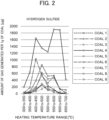
FIG. 2] FIG. 2 is a graph showing an amount of hydrogen sulfide (H2S) generated in each heating temperature range. - [
FIG. 3] FIG. 3 is a graph showing an amount of sulfur dioxide (SO2) generated in each heating temperature range. - A method for quantifying gas generated from coal according to the present embodiment (hereinafter, also referred to as "present quantification method" for convenience) includes: a gas collection step of collecting gas generated during heating of coal; a gas introduction step of introducing the gas collected in the gas collection step into a separation column of a gas chromatograph; a gas capturing step of capturing the gas introduced into the separation column by cooling the separation column; a gas releasing step of releasing the gas captured in the gas capturing step by deactivating the cooling of the separation column; and an analysis step of analyzing and quantifying the gas released in the gas releasing step by a mass spectrometry unit.
-
FIG. 1 is a schematic view illustrating anapparatus 1 used for quantification of gas generated from coal. - The
apparatus 1 includes achamber 2. Aseparation column 3 of a gas chromatograph, aheating unit 4 heating theseparation column 3, and acooling unit 5 cooling at least a part, in a length direction, of theseparation column 3 are provided inside thechamber 2. - The
apparatus 1 further includes agas injection unit 6 injecting gas into theseparation column 3, and amass spectrometry unit 7 separating and specifying a gas component contained in the gas introduced from theseparation column 3 according to a mass-to-charge ratio. - The heating method of the
heating unit 4 is not particularly limited as long as the temperature can be controlled when theseparation column 3 is heated, and examples thereof include a heating furnace method using a resistance heater and a high-frequency induction heating method. - The cooling method of the
cooling unit 5 is not particularly limited as long as at least a part of theseparation column 3 can be cooled and controlled to an arbitrary temperature, and examples thereof include conventionally known methods such as a Peltier cooling method and a liquid nitrogen cooling method. - The cooling range of the
cooling unit 5 is not particularly limited, but it is preferable that at least a range of a length of about 10 mm in theseparation column 3 can be cooled. - One favorable example of the
cooling unit 5 as above is a cryotrap. The cryotrap is a facility that is disposed in the middle of theseparation column 3 and blows nitrogen gas cooled with liquid nitrogen to theseparation column 3 from the outside. - In the case of using a cryotrap as the
cooling unit 5, since the separation capacity by the cryotrap is large, the type and polarity of theseparation column 3 may be freely selected. - The
apparatus 1 may further include apyrolysis furnace 8. Gas is generated from coal by heating the coal using thepyrolysis furnace 8. - The
pyrolysis furnace 8 may be any furnace as long as it has heating capability corresponding to the heating temperature of the coal to be charged into thepyrolysis furnace 8. As the heating method of thepyrolysis furnace 8, a conventionally known method can be adopted, and examples thereof include a filament type in which heating is performed by a filament, an induction heating type in which a sample foil made of alloy is heated by a high-frequency magnetic field, and a heating furnace type. - Hereinafter, each step included in the present quantification method performed using the
apparatus 1 will be described in detail. - The gas collection step is a step of collecting gas generated during heating of coal.
- In the gas collection step, it is preferable that coal is charged into the
pyrolysis furnace 8 and heated. In this way, gas generated from the coal heated inside thepyrolysis furnace 8 is collected. - The atmosphere in the furnace of the
pyrolysis furnace 8 is preferably an inert gas atmosphere in order to avoid superposition of peaks in themass spectrometry unit 7 in the case of simulating the atmosphere during coal carbonization in a coke oven. The inert gas is preferably helium (He), and may be nitrogen (N2) or the like. - Coal to be charged into the
pyrolysis furnace 8 is preferably pulverized to a certain grain size or less in order to prevent temperature unevenness during heating. Specifically, the grain size of the coal is preferably 250 um or less and more preferably 125 um or less. When the grain size of the coal is too large, uniform heating is difficult, and unevenness in the amount of gas generated occurs, so that the analysis accuracy in themass spectrometry unit 7 may be deteriorated. - In order to reduce the influence of moisture in the
mass spectrometry unit 7, it is preferable to use well-air-dried coal. - The amount of coal corresponding to the volume of the
pyrolysis furnace 8 is charged into thepyrolysis furnace 8. However, when the amount of coal to be charged into thepyrolysis furnace 8 is too large, there is a risk that a large amount of gas is captured in theseparation column 3 by use of thecooling unit 5 and theseparation column 3 is clogged. Therefore, the amount of coal to be charged into thepyrolysis furnace 8 is preferably about 70 to 80% of the volume of thepyrolysis furnace 8. - The gas generated during heating of coal contains hydrogen and hydrocarbons (CmHn) having various molecular weights. Examples of low-molecular-weight hydrocarbons include methane (CH4), ethane (C2H6), and ethylene (C2H4). Examples of high-molecular-weight hydrocarbons include n-hexane (C6H14) and n-decane (C10H22), and m > 10 may be satisfied.
- The gas generated during heating of coal further contains a sulfur-based gas. The sulfur-based gas contains, for example, a gas component such as hydrogen sulfide (H2S), carbonyl sulfide (COS), sulfur dioxide (SO2), carbon disulfide (CS2), or thiophene (C4H4S).
- Of the gas generated during heating of coal, gas generated at a specific heating temperature A or a heating temperature range B may be quantified.
- In this case, it is preferable to previously provide a step (preliminary heating step) of heating coal at a temperature (preliminary heating temperature) lower than the heating temperature A or a lower limit temperature of the heating temperature range B and discharging the generated gas.
- The preliminary heating temperature may be set in consideration of a control range of the temperature inside the
pyrolysis furnace 8. For example, when the control range is smaller than 5°C, the preliminary heating temperature is set to be lower than the heating temperature A or the lower limit of the heating temperature range B by 5°C. - The time for heating coal at the preliminary heating temperature may be any period of time as long as the time is long enough for gas to be no longer generated from the coal by heating at the preliminary heating temperature, and is, for example, 10 minutes or more and preferably 15 minutes or more.
- A discharge path of the gas generated in the preliminary heating step is not particularly limited. The gas may be discharged from a split path (not illustrated), or may be allowed to pass through the
separation column 3 of the gas chromatograph and discharged. - When the gas is allowed to pass through the
separation column 3, it is preferable to confirm that no gas is detected by themass spectrometry unit 7 before the gas collection step. - In the case of quantifying the gas generated at the heating temperature A, after the preliminary heating step, the coal is heated in the
pyrolysis furnace 8 set at the heating temperature A for a certain period of time to generate gas. - When the heating time is too short, the entire amount of coal is not sufficiently heated, and the entire amount of gas generated at the heating temperature A cannot be collected in some cases. Therefore, the heating time is preferably 10 minutes or more and more preferably 15 minutes or more.
- In the case of quantifying the gas in the heating temperature range B, after the preliminary heating step, the temperature inside the
pyrolysis furnace 8 is raised from the lower limit temperature to the upper limit temperature of the heating temperature range B to generate gas from the coal. - When the temperature rise rate is too high, the heating of the coal at each temperature in the temperature raising process is insufficient, and the entire amount of gas generated over the entire heating temperature range B cannot be collected in some cases. Therefore, the temperature rise rate is preferably 10°C/min or less and more preferably 5°C/min or less.
- After the temperature raising process, a step of heating at an upper limit temperature may be added.
- In the gas introduction step, the gas collected in the gas collection step is introduced into the
separation column 3 of the gas chromatograph from thegas injection unit 6 by using a carrier gas. - The gas introduced into the
separation column 3 flows together with the carrier gas from one end (the end on thegas injection unit 6 side) toward the other end (the end on themass spectrometry unit 7 side) of theseparation column 3. - In order to simulate a coke oven, the carrier gas is preferably an inert gas and more preferably a He gas having less influence in the
mass spectrometry unit 7. The flow rate and the split ratio of the carrier gas are not particularly limited, and may be appropriately adjusted according to the analysis sensitivity of themass spectrometry unit 7 or the like. - In the gas capturing step, the cooling unit 5 (for example, a cryotrap) is operated to cool at least a part, in the length direction, of the
separation column 3 to a certain cooling temperature. - Hereinafter, for convenience, the portion of the
separation column 3 cooled by thecooling unit 5 may be referred to as a "cooling target portion", and the portion of theseparation column 3 that is not the cooling target portion may be referred to as a "non-cooling target portion". - The gas introduced into the
separation column 3 is solidified in the cooling target portion of theseparation column 3 by the operation of thecooling unit 5, and is captured inside theseparation column 3. - For example, a case where gas to be introduced into the
separation column 3 is a sulfur-based gas is considered. Among the gas components contained in the sulfur-based gas, since hydrogen sulfide has a lowest boiling point of -60°C, the cooling temperature of theseparation column 3 is set to a temperature lower than - 60°C. As a result, while thecooling unit 5 is operating, all the gas components having boiling points of -60°C or higher are captured in theseparation column 3. - A case where the gas introduced into the
separation column 3 is a gas generated during heating of coal is considered. - Examples of gas components other than the sulfur-based gas among the gas components contained in the gas generated during heating of coal include hydrogen (boiling point: -252.6°C); low-molecular-weight hydrocarbons such as methane (boiling point: -162°C), ethylene (boiling point: - 103.7°C), and ethane (boiling point: -89°C); and high-molecular-weight hydrocarbons such as n-hexane (boiling point: 69°C) and n-decane (boiling point: 174°C).
- Among them, a gas component (hydrogen, a low-molecular-weight hydrocarbon, or the like) having a boiling point lower than the cooling temperature of the
separation column 3 passes through theseparation column 3 without being captured by theseparation column 3. - On the other hand, the gas components (a high-molecular-weight hydrocarbon and the like) having a boiling point equal to or higher than the cooling temperature of the
separation column 3 are all captured in theseparation column 3 together with the sulfur-based gas. - The time for cooling the cooling target portion of the
separation column 3 is not particularly limited, and is, for example, about 30 seconds to 1 minute. - The temperature inside the chamber 2 (that is, the temperature of the non-cooling target portion of the separation column 3) is preferably 100°C or lower, more preferably 80°C or lower, and still more preferably 50°C or lower. The lower limit is not particularly limited, and is, for example, room temperature (for example, 25°C).
- The temperature control inside the
chamber 2 is performed by operating theheating unit 4. - When the temperature inside the
chamber 2 is in the above range, the temperature gradient between the cooling target portion and the non-cooling target portion of theseparation column 3 is gentle during the operation of thecooling unit 5. As a result, the influence range of the cooling unit 5 (that is, the cooling target portion of the separation column 3) is widened, and the analysis error in themass spectrometry unit 7 can be reduced in the analysis step described below. - Also in the next gas releasing step, the temperature inside the
chamber 2 is preferably in the above range for the reason described below. - In the gas releasing step, the captured gas is released by deactivating the cooling of the
separation column 3. - The cooling is deactivated by turning off the operation of the cooling unit 5 (for example, a cryotrap). As a result, the temperature of the cooling target portion of the
separation column 3 rises, and the solidified gas component volatilizes. At this time, the gas components are volatilized in order from a gas component having a lower boiling point, move forward inside theseparation column 3, and are introduced into themass spectrometry unit 7 with a time difference. The influence of the separation capacity due to the boiling point difference is larger than that of the separation capacity due to the column polarity. - The gas components reach the
mass spectrometry unit 7 in ascending order of boiling point. Therefore, into themass spectrometry unit 7, a low-molecular-weight hydrocarbon (hydrocarbon-based gas) is first introduced, then a sulfur-based gas is volatilized and introduced, and a high-molecular-weight hydrocarbon (hydrocarbon-based gas) is finally introduced. - A low-molecular-weight hydrocarbon-based gas such as methane, ethane, or ethylene has a smaller mass-to-charge ratio (m/z) than the sulfur-based gas. Therefore, a peak superposed with the sulfur-based gas does not occur.
- On the other hand, a high-molecular-weight hydrocarbon-based gas generates fragment ions having the same mass-to-charge ratio (m/z) as that of the sulfur-based gas when ionized by the
mass spectrometry unit 7. Therefore, a peak superposed with the sulfur-based gas occurs, and the peak of the sulfur-based gas cannot be separated with high accuracy. - However, in the present embodiment, the high-molecular-weight hydrocarbon-based gas is introduced into the
mass spectrometry unit 7 after the sulfur-based gas. Therefore, the sulfur-based gas can be analyzed by themass spectrometry unit 7 while avoiding superposition of peaks caused by the high-molecular-weight hydrocarbon-based gas containing no sulfur. That is, the sulfur-based gas generated during heating of coal can be quantified with high accuracy. - Meanwhile, in the gas releasing step, when the temperature inside the chamber 2 (the temperature of the non-cooling target portion of the separation column 3) is too high (for example, 300°C), the rate of temperature rise of the cooling target portion of the
separation column 3 may become too high after the deactivation of the cooling. - In this case, not only the sulfur-based gas but also the high-molecular-weight hydrocarbon-based gas that affects the analysis of the sulfur-based gas immediately reaches the temperature inside the
chamber 2 and is likely to volatilize. Then, in themass spectrometry unit 7, the superposition of both the gases is likely to occur, and there is a possibility that the quantitative accuracy of the sulfur-based gas is insufficient. - Therefore, also in the gas releasing step, the temperature inside the
chamber 2 is preferably in the above range. That is, the temperature inside thechamber 2 is preferably 100°C or lower, more preferably 80°C or lower, and still more preferably 50°C or lower. - With this, the rate at which the cooling target portion of the
separation column 3 whose cooling has been deactivated rises in temperature can be made slow, and as a result, the sulfur-based gas having a lower boiling point volatilizes before the high-molecular-weight hydrocarbon-based gas that affects the analysis of the sulfur-based gas, and is easily introduced into themass spectrometry unit 7. That is, it is easy to quantify the sulfur-based gas generated during heating of coal with high accuracy. - <Temperature rise heating step>
- The present quantification method preferably further includes a temperature rise heating step of raising a temperature to heat the
separation column 3 in addition to the gas releasing step. - Specifically, for example, the cooling of the
separation column 3 is deactivated, and the temperature is raised to heat theseparation column 3. The temperature rise heating of theseparation column 3 is performed by operating theheating unit 4 to raise the temperature and heat the inside of thechamber 2. - The temperature rise rate at this time is, for example, 5°C/min or more.
- On the other hand, for the reasons described above, the temperature rise rate is preferably not too high, and specifically, the temperature rise rate is preferably 20°C/min or less, more preferably 15°C/min or less, and still more preferably 10°C/min or less.
- In the analysis step, the gas (sulfur-based gas) released in the gas releasing step is analyzed and quantified by the
mass spectrometry unit 7. - The
mass spectrometry unit 7 separates and specifies gas components contained in the sulfur-based gas released in the gas releasing step according to the mass-to-charge ratio. - In the present embodiment, with respect to hydrogen sulfide (H2S, m/z: 34), carbonyl sulfide (COS, m/z: 60), sulfur dioxide (SO2, m/z: 64), carbon disulfide (CS2, m/z: 76), and thiophene (C4H4S, m/z: 84), which are main low-molecular-weight gas components contained in the sulfur-based gas, a mass spectrum with a single peak is obtained at each mass-to-charge ratio (m/z). The tendency of the amount of each gas component can be grasped by the magnitude of the peak area.
- Separately, each gas component is quantified by using a peak area of each gas component having a known concentration obtained under the same conditions as a calibration curve.
- After the analysis in the
mass spectrometry unit 7 is completed, theheating unit 4 is preferably operated to heat the inside of thechamber 2 for the purpose of removing hydrocarbon remaining in theseparation column 3. At this time, the temperature inside thechamber 2 is preferably 200°C or higher and more preferably 300°C or higher. - Next, a method for estimating an amount of gas generated during coal carbonization according to the present embodiment (hereinafter, also referred to as "present estimation method") will be described.
- The following description also serves as a description of a method for manufacturing coke according to the present embodiment (hereinafter, also referred to as "present manufacturing method").
- In the present estimation method, first, the sulfur-based gas generated during heating of coal is quantified by performing the above-described present quantification method.
- In this process, as shown in EXAMPLES described below, it is preferable to quantify each gas component (such as hydrogen sulfide or sulfur dioxide) contained in the sulfur-based gas generated during heating of coal.
- It is also preferable to repeatedly perform the above-described present quantification method. In this case, as shown in EXAMPLES described below, in the gas collection step, coal is heated at different heating temperatures or in heating temperature ranges, and gas thereby generated is collected.
- Based on the obtained quantitative results, the generation temperature or generation temperature range and the generation amount of sulfur-based gas generated during coal carbonization in a coke oven are estimated.
- When n kinds of coal are blended, charged into a coke oven, and subjected to carbonization, a generation amount F(T) of sulfur-based gas is represented by, for example, the following formula.

- In the above formula, fn(T) is a function of temperature indicating the amount of sulfur-based gas generated from coal, and An is a blending ratio of coal.
- The operation of the coke oven is performed by operating a plurality of coke ovens.
- Therefore, focusing on F(T) of each coke oven, the operating times of the respective coke ovens are adjusted so that the amounts of sulfur-based gas generated are distributed with respect to time.
- With this configuration, it is possible to prevent a high-concentration sulfur-based gas from locally flowing into a desulfurization facility provided downstream of each coke oven, and the operation of the coke oven can be stabilized.
- In addition, when coke is actually manufactured by coal carbonization, a manufacturing condition of coke such as a coal blending ratio can be modified based on an estimation result obtained by the present estimation method. The estimation result can also be utilized for selection of coal suitable for coke oven operation.
- Hereinafter, the present invention will be specifically described with reference to Examples. However, the present invention is not limited to Examples described below.
- According to the method described in JIS M 8811 "Coal and coke - Sampling and sample preparation", each of nine kinds of coal (
Coals 1 to 9) was sampled in an amount of 100 g. Each coal was pulverized and classified to 125 um or less and air-dried at 40°C for 4 hours. - The total sulfur amounts (unit: mass%) of
Coals 1 to 9 are shown in Table 1 below. The total sulfur amount is a value obtained by performing measurement using a high temperature combustion method described in JIS M 8813 "Coal and coke - Determination of constituents" and converting the measured value into a mass value per 1 g of coal. -
Table 1 Total sulfur amount [mass%] Coal 10.48 Coal 20.50 Coal 30.43 Coal 42.05 Coal 50.82 Coal 60.56 Coal 70.38 Coal 80.95 Coal 90.40 - For
Coals 1 to 9 shown in Table 1 above, the sulfur-based gas generated during heating of coal was quantified using theapparatus 1 described based onFIG. 1 . - More specifically, the generation amounts of respective gas components (hydrogen sulfide, carbonyl sulfide, sulfur dioxide, carbon disulfide, and thiophene) were determined for each heating temperature range in a range of 300 to 700°C at intervals of 50°C.
- As the
cooling unit 5, a cryotrap was used. As thegas injection unit 6 and thepyrolysis furnace 8, a pyrolyzer was used. Each coal was collected in an amount of 5 mg and charged into thepyrolysis furnace 8. - The atmosphere in the furnace of the
pyrolysis furnace 8 was set to an atmosphere of He gas being a carrier gas. The He gas was introduced from thepyrolysis furnace 8 into thegas injection unit 6, theseparation column 3, and themass spectrometry unit 7 at a flow rate of 1 L/min and a split ratio of 1 : 50. - First, each gas component was quantified in a heating temperature range of 300 to 350°C.
- First, the coal charged into the
pyrolysis furnace 8 was heated at a preliminary heating temperature of 295°C for 10 minutes. As a result, the attached moisture and the gas generated in a heating temperature range of 295°C or lower were discharged through a split path (or a path passing through the separation column 3) (preliminary heating step). - Thereafter, the coal was moved to a retreat place of the
pyrolysis furnace 8, and then the temperature inside thepyrolysis furnace 8 was raised to 300°C. - Next, while the
heating unit 4 was operated to bring the temperature inside the chamber 2 (that is, the temperature of the non-cooling target portion of the separation column 3) to 40°C, the cooling unit 5 (cryotrap) was operated to cool the cooling target portion of theseparation column 3 to -180°C. - In this state, the coal was returned to the furnace of the
pyrolysis furnace 8, the temperature in the furnace was raised at 3°C/min to reach 350°C, and then the coal was held for 5 minutes. In this way, gas was generated from the coal (gas collection step). Thereafter, the coal was moved to the retreat place of thepyrolysis furnace 8. - The gas generated from the coal was introduced into the
separation column 3 from thegas injection unit 6 using a carrier gas (gas introduction step), and solidified in the cooling target portion of theseparation column 3 cooled to -180°C (gas capturing step). The cooling of theseparation column 3 was continuously performed during the charging of the coal into the furnace of thepyrolysis furnace 8. - Subsequently, the operation of the
cooling unit 5 was turned off to release the cooling of the separation column 3 (gas releasing step). At the same time, theheating unit 4 was operated to increase the temperature inside thechamber 2 to 300°C at 10°C/min (temperature rise heating step) . - The gas solidified in the cooling target portion of the
separation column 3 volatilized, moved by the carrier gas in the ascending order of boiling point, and reached themass spectrometry unit 7. The gas having reached themass spectrometry unit 7 was separated according to the mass-to-charge ratio, and components thereof were specified (analysis step). - With respect to hydrogen sulfide (H2S, m/z: 34), carbonyl sulfide (COS, m/z: 60), sulfur dioxide (SO2, m/z: 64), carbon disulfide (CS2, m/z: 76), and thiophene (C4H4S, m/z: 84) generated during heating of coal, a mass spectrum with a single peak was obtained at each mass-to-charge ratio.
- The peak area of each gas component was converted using a calibration curve prepared in advance (the peak area of each gas component having a known concentration obtained under the same conditions), thus quantifying each gas component.
- Next, the
heating unit 4 was operated to heat the inside of thechamber 2 at 300°C for 30 minutes. As a result, hydrocarbon remaining inside theseparation column 3 was removed. Thereafter, the inside of thechamber 2 was cooled to 40°C. - Subsequently, each gas component was quantified in a heating temperature range of 350 to 400°C.
- First, in a state where the temperature inside the
chamber 2 was 40°C, thecooling unit 5 was operated to cool the cooling target portion of theseparation column 3 to - 180°C. The coal having been moved to the retreat place of thepyrolysis furnace 8 was introduced into thepyrolysis furnace 8 set at 350°C, which was the upper limit of the previous heating temperature range (300 to 350°C), and heated for 5 minutes (preliminary heating step). - Next, the temperature inside the
pyrolysis furnace 8 was raised at 3°C/min to reach 400°C, and then the coal was held for 5 minutes. In this way, gas was generated from the coal (gas collection step). Thereafter, the coal was moved to the retreat place of thepyrolysis furnace 8. - In the subsequent steps, each gas component was quantified in the same manner as in the step in the previous heating temperature range of 350 to 400°C.
- In this way, each gas component was quantified in a range of 300 to 700°C while the heating temperature range was shifted at intervals of 50°C.
- Based on the obtained quantitative results, the generation amounts of the respective gas components generated during heating of
Coals 1 to 9 were organized for each heating temperature range. - As representatives, the results of hydrogen sulfide (H2S) are shown in Table 2 below and the graph of
FIG. 2 , and the results of sulfur dioxide (SO2) are shown in Table 3 and the graph ofFIG. 3 . -
Table 2 Heating temperature range [°C] 300 to 350 350 to 400 400 to 450 450 to 500 500 to 550 550 to 600 600 to 650 650 to 700 Hydrogen sulfide (H2S) Coal 112.67 50.17 387.39 848.94 522.24 535.85 137.34 112.85 Coal 228.04 174.39 1033.11 554.81 233.06 125.74 14.23 23.96 Coal 37.66 12.58 98.71 293.93 178.30 45.70 46.49 7.78 Coal 4195.77 636.12 1643.50 1350.47 1240.47 1905.45 1892.52 424.13 Generation amount per 1 g of coal [µg/g] Coal 518.73 37.82 165.72 619.49 443.17 461.72 145.69 21.43 Coal 621.92 26.49 102.51 262.93 120.70 106.29 10.74 16.51 Coal 72.99 11.07 65.82 133.88 241.81 122.85 3.78 3.91 Coal 836.69 69.99 191.75 538.72 314.23 521.35 131.07 37.72 Coal 95.64 16.85 145.17 258.72 103.42 58.42 3.50 7.07 -
Table 3 Heating temperature range [°C] 300 to 350 350 to 400 400 to 450 450 to 500 500 to 550 550 to 600 600 to 650 650 to 700 Sulfur dioxide (SO2) Coal 10.00 59.96 208.74 84.69 6.08 28.23 141.61 13.03 Coal 2114.43 112.36 25.77 32.22 7.90 125.51 176.50 95.99 Coal 336.26 20.14 30.16 21.28 0.00 31.87 121.75 111.77 Coal 41517.73 1106.61 671.40 3781.99 172.27 30.35 141.28 148.35 Generation amount per 1 g of coal [µg/g] Coal 594.08 69.63 86.10 69.62 51.21 43.71 36.47 126.52 Coal 6123.70 101.12 283.72 456.71 147.58 73.41 63.12 80.87 Coal 729.89 35.05 77.01 54.84 0.65 16.91 78.84 113.89 Coal 8358.42 239.09 176.53 743.72 73.89 28.87 100.89 142.77 Coal 933.05 30.98 60.28 23.67 0.00 36.71 83.18 53.12 - The outline of the graph varies depending on the brand of coal, but a large tendency is as follows.
- As for hydrogen sulfide (H2S), most of the coal had a peak of the amount of hydrogen sulfide generated at each of a low temperature side and a high temperature side with the 500°C boundary (see Table 2 and
FIG. 2 ). - As for sulfur dioxide (SO2), two peaks were generated on a low temperature side and a high temperature side with the boundary around 550°C, and
Coal 4,Coal 6, andCoal 8 showed particularly strong peaks at around 450°C (see Table 3 andFIG. 3 ). - As described above, it was found that the generation amount of sulfur-based gas generated during heating of coal greatly changes depending on the heating temperature.
- This is considered to be caused by a difference in the existence form of sulfur in coal.
- Sulfur-based gases generated during heating of coal have various generation temperatures depending on the existence form of sulfur in the coal. For example, the peak of sulfur dioxide observed at around 500°C is considered to have appeared due to decomposition of sulfate sulfur. From these results, the amount of sulfur-based gas generated when coke is actually manufactured by coal carbonization is presumed to vary depending on the temperature during coal carbonization.
- As described above, for each brand of coal, the generation amounts of sulfur-based gas can be organized for each generation temperature range. Therefore, for example, the coal blending ratio can be set in advance so that a large amount of sulfur-based gas is not generated at a certain temperature, and contribution to stable manufacturing of coke is expected.
-
- 1:
- apparatus used for quantification of gas generated from coal
- 2:
- chamber
- 3:
- separation column
- 4:
- heating unit
- 5:
- cooling unit
- 6:
- gas injection unit
- 7:
- mass spectrometry unit
- 8:
- pyrolysis furnace
Claims (6)
- A method for quantifying gas generated from coal, comprising:a gas collection step of collecting gas generated during heating of coal;a gas introduction step of introducing the gas collected in the gas collection step into a separation column of a gas chromatograph;a gas capturing step of capturing the gas introduced into the separation column by cooling the separation column;a gas releasing step of releasing the gas captured in the gas capturing step by deactivating the cooling of the separation column; andan analysis step of analyzing and quantifying the gas released in the gas releasing step by a mass spectrometry unit.
- The method for quantifying gas generated from coal according to claim 1, further comprising a temperature rise heating step of raising a temperature to heat the separation column the cooling of which has been deactivated.
- The method for quantifying gas generated from coal according to claim 1 or 2,
wherein the gas contains a sulfur-based gas. - A method for estimating an amount of gas generated during coal carbonization, comprising estimating a generation temperature or generation temperature range and a generation amount of a sulfur-based gas generated during coal carbonization based on a quantitative result obtained by the method for quantifying according to claim 3.
- A method for manufacturing coke by subjecting coal to carbonization,
wherein a manufacturing condition of coke is modified based on an estimation result obtained by the method for estimating according to claim 4. - The method for manufacturing coke according to claim 5,
wherein the manufacturing condition is a coal blending ratio.
Applications Claiming Priority (2)
| Application Number | Priority Date | Filing Date | Title |
|---|---|---|---|
| JP2022016874A JP7722209B2 (en) | 2022-02-07 | 2022-02-07 | Method for quantifying gas generated from coal, method for estimating gas generation amount during coal carbonization, and method for manufacturing coke |
| PCT/JP2022/042941 WO2023149053A1 (en) | 2022-02-07 | 2022-11-21 | Method for quantifying gas generated from coal, method for estimating amount of gas generated during coal carbonization, and method for manufacturing coke |
Publications (2)
| Publication Number | Publication Date |
|---|---|
| EP4443156A1 true EP4443156A1 (en) | 2024-10-09 |
| EP4443156A4 EP4443156A4 (en) | 2025-03-12 |
Family
ID=87552161
Family Applications (1)
| Application Number | Title | Priority Date | Filing Date |
|---|---|---|---|
| EP22924958.6A Pending EP4443156A4 (en) | 2022-02-07 | 2022-11-21 | Method for quantifying gas produced from coal, method for estimating the amount of gas produced during coal carbonization, and method for producing coke |
Country Status (3)
| Country | Link |
|---|---|
| EP (1) | EP4443156A4 (en) |
| JP (1) | JP7722209B2 (en) |
| WO (1) | WO2023149053A1 (en) |
Family Cites Families (5)
| Publication number | Priority date | Publication date | Assignee | Title |
|---|---|---|---|---|
| US4517461A (en) * | 1982-11-29 | 1985-05-14 | Phillips Petroleum Co | Carbon isotope analysis of hydrocarbons |
| WO2005042673A1 (en) * | 2003-10-30 | 2005-05-12 | Council Of Scientific & Industrial Research | Method for predicting amount of gas produced during coal gasification |
| JP4571892B2 (en) * | 2005-07-05 | 2010-10-27 | フロンティア・ラボ株式会社 | Polymer sample analyzer |
| JP4927020B2 (en) * | 2008-04-16 | 2012-05-09 | 新日本製鐵株式会社 | Quantitative determination method for sulfur in coal |
| CN102375041B (en) * | 2011-09-16 | 2015-03-04 | 武汉市天虹仪表有限责任公司 | Online volatile organic matter analyzer and using method thereof |
-
2022
- 2022-02-07 JP JP2022016874A patent/JP7722209B2/en active Active
- 2022-11-21 EP EP22924958.6A patent/EP4443156A4/en active Pending
- 2022-11-21 WO PCT/JP2022/042941 patent/WO2023149053A1/en not_active Ceased
Also Published As
| Publication number | Publication date |
|---|---|
| JP2023114530A (en) | 2023-08-18 |
| WO2023149053A1 (en) | 2023-08-10 |
| EP4443156A4 (en) | 2025-03-12 |
| JP7722209B2 (en) | 2025-08-13 |
Similar Documents
| Publication | Publication Date | Title |
|---|---|---|
| CN101144795B (en) | Pulse fusion-time-of-flight mass spectrometry elemental analyzer | |
| CN107101961B (en) | A kind of method of Trace Metals Contents in aas determination pitch | |
| CN103134851A (en) | Direct measuring apparatus and measuring method for hydrogen sulfide content and sulfur isotope in natural gas | |
| KR20160072664A (en) | Method of sample quality prediction | |
| JP7832555B2 (en) | Quantitative analysis method and quantitative analysis apparatus | |
| CN103091440A (en) | Method for qualitatively and quantitatively analyzing trace impurities in SF6 (Sulfur Hexafluoride) gas | |
| CN110554136A (en) | Method for detecting sulfur content in blast furnace gas | |
| DE102008007354A1 (en) | High temperature tube furnace for pyrolysis | |
| JP7722209B2 (en) | Method for quantifying gas generated from coal, method for estimating gas generation amount during coal carbonization, and method for manufacturing coke | |
| JP2019163986A (en) | Coke analysis method | |
| CN104198319B (en) | A kind of device and its application process for studying cigarette additive cracking process | |
| EP4227677A1 (en) | Substance pyrolysis real-time online analysis device and method for using same | |
| Klemetsrud et al. | A kinetic study of the fast micro-pyrolysis of hybrid poplar | |
| EP3108240B1 (en) | Analyzer for analyzing carbon (c) and sulfur (s) in metals | |
| JP6874937B2 (en) | Quantitative analyzer for oxygen generated from battery material | |
| Nguyen Tu et al. | Variability of 13C‐labeling in plant leaves | |
| KR101277955B1 (en) | Estimation method of caloric value of fine coal for blast furnace injecting | |
| CN107238663B (en) | System and method for detecting residual components after combustion by using large-volume headspace sampler | |
| CN113468462B (en) | Method for predicting sulfur content in coke oven gas | |
| Protić et al. | Thermogravimetric analysis of biomass and sub-bituminous coal | |
| CN106547935A (en) | A kind of method for building up of smelter coke stomatal apparatus type forecast model | |
| JP2023181095A (en) | Outgas evaluation method | |
| JP5884187B2 (en) | Carbon steel refining method | |
| JP7354011B2 (en) | Method for confirming that no hydrocarbons remain in roasted waste substrates | |
| EP4400562A1 (en) | Method for estimating code strength after reaction and method for manufacturing coke |
Legal Events
| Date | Code | Title | Description |
|---|---|---|---|
| STAA | Information on the status of an ep patent application or granted ep patent |
Free format text: STATUS: THE INTERNATIONAL PUBLICATION HAS BEEN MADE |
|
| PUAI | Public reference made under article 153(3) epc to a published international application that has entered the european phase |
Free format text: ORIGINAL CODE: 0009012 |
|
| STAA | Information on the status of an ep patent application or granted ep patent |
Free format text: STATUS: REQUEST FOR EXAMINATION WAS MADE |
|
| 17P | Request for examination filed |
Effective date: 20240703 |
|
| AK | Designated contracting states |
Kind code of ref document: A1 Designated state(s): AL AT BE BG CH CY CZ DE DK EE ES FI FR GB GR HR HU IE IS IT LI LT LU LV MC ME MK MT NL NO PL PT RO RS SE SI SK SM TR |
|
| A4 | Supplementary search report drawn up and despatched |
Effective date: 20250211 |
|
| RIC1 | Information provided on ipc code assigned before grant |
Ipc: G01N 25/38 20060101ALI20250205BHEP Ipc: G01N 33/22 20060101ALI20250205BHEP Ipc: G01N 30/72 20060101ALI20250205BHEP Ipc: G01N 30/06 20060101ALI20250205BHEP Ipc: G01N 27/62 20210101ALI20250205BHEP Ipc: C10B 57/04 20060101ALI20250205BHEP Ipc: G01N 30/08 20060101AFI20250205BHEP |
|
| DAV | Request for validation of the european patent (deleted) | ||
| DAX | Request for extension of the european patent (deleted) |