EP4443116A1 - Draft shield comprising a swiveling door - Google Patents
Draft shield comprising a swiveling door Download PDFInfo
- Publication number
- EP4443116A1 EP4443116A1 EP23166631.4A EP23166631A EP4443116A1 EP 4443116 A1 EP4443116 A1 EP 4443116A1 EP 23166631 A EP23166631 A EP 23166631A EP 4443116 A1 EP4443116 A1 EP 4443116A1
- Authority
- EP
- European Patent Office
- Prior art keywords
- door
- wall
- draft shield
- swivel
- shaft
- Prior art date
- Legal status (The legal status is an assumption and is not a legal conclusion. Google has not performed a legal analysis and makes no representation as to the accuracy of the status listed.)
- Granted
Links
Images



Classifications
-
- G—PHYSICS
- G01—MEASURING; TESTING
- G01G—WEIGHING
- G01G21/00—Details of weighing apparatus
- G01G21/30—Means for preventing contamination by dust
-
- G—PHYSICS
- G01—MEASURING; TESTING
- G01G—WEIGHING
- G01G21/00—Details of weighing apparatus
- G01G21/28—Frames, Housings
- G01G21/286—Frames, Housings with windshields
Definitions
- the present disclosure relates to a draft shield comprising a swiveling door. More in particular, the herein claimed invention relates to the subject matter set forth in the claims.
- Draft shields are used for instance in connection with high precision balances to shield the weighing goods and mechanics from environmental influences, like movements of air, which could otherwise detrimentally influence high precision measurements. Draft shields, as such, are abundantly known in the art.
- draft shields comprise doors through which a weighing good can be transferred into and out of the interior space or weighing chamber defined by the draft shield.
- the doors are sliding side doors which are displaced from the front to the back of the balance for opening.
- the width of the draft shield is at least as large as the width of the housing of the balance which contains the electronics and a weighing cell. This issue gets the more accentuated in so-called front loader balances, in which the weighing cell, i.e., the transducer transforming the gravitational force of the weighing good into an electric signal, is placed behind the weighing pan.
- Said type of balances yields certain advantages which are not to be discussed in detail in this context.
- the size of the housing increases for instance when compared to a so-called top loader balance.
- the draft shield narrower than the housing of the balance which contains the electronics and a weighing cell. This, in turn, prevents opening the sliding side doors by a displacement towards the back of the balance, i.e., the use of slide doors which open towards the back of the balance is not possible.
- Opening the sliding doors by displacement to the front of the balance is generally possible, however restricts the capability, for instance, to place a terminal conveniently in front of the balance.
- a further drawback related to sliding doors in general may be seen in that the sliding doors are guided in guideways. Cleaning of the guideways may turn out fairly difficult, while dirt in a guideway may result in cross-contamination and eventually increase resistance and impede movement of the door.
- doors for draft shields may be hingedly attached to a stationary housing of the draft shield, wherein the hinge axis extends parallel to an edge of the door. It will be appreciated that the movement of a hinged door requires a relatively large space on the side of the draft shield. Furthermore, as opening and closing a hinged door involves movement of the door perpendicular to its face, said movement may itself result in agitating the air inside the draft shield, which may in turn agitate the weighing pan with the weighing good placed thereon and thus yield detrimental effects on the precision of the measurement.
- a draft shield of the type initially mentioned is suggested.
- a draft shield shall be suggested that overcomes certain drawbacks of the prior art.
- the herein proposed draft shield shall overcome the drawbacks of the art mentioned above.
- the draft shield shall be applicable in applications wherein a housing of the balance which contains the electronics and/or a weighing cell is wider than the draft shield, or, other way round, the draft shield is narrower than said housing of the balance.
- This may provide the possibility to even further restrict a volume contained inside the draft shield to a size required to include a weighing pan and the weighing good, and, as the case may be, further elements required for the function of the balance, such as devices for automatic handling of weighing goods inside the weighing chamber defined inside the draft shield, without opening a door.
- guideways which might in some cases be prone to contamination and/or may be difficult to clean shall be avoided.
- the doors of the draft shield shall be provided to minimize agitation of air inside the draft shield during opening and closing of a door.
- a draft shield for a balance comprising a first wall, a second wall and at least one door, i.e., at least a first door.
- the first door may, in embodiments, be the only door, but in common embodiments be a first one of two doors. It is further not excluded that the first door might be one door out of two or more doors.
- One of the first and second walls may be a top wall of the draft shield, while the other one of first and second walls may be a front wall of the draft shield.
- the first wall may be a top wall of the draft shield, while the second wall is a front wall of the draft shield.
- the first wall and the second wall adjoin each other perpendicularly and the first door is provided perpendicular to each of the first wall and the second wall.
- the first door is arranged and configured to swivel between a closed position and an open position, wherein in the closed position the first door adjoins a first edge of the first wall and a first edge of the second wall, wherein a swivel axis of the first door extends perpendicular to a face of the first door such that the first door is configured to swivel in the plane of the first door, i.e., a plane defined by an areal extent of the door, which may be considered at least essentially plate-shaped.
- Adjoin shall indicate that two elements are provided in close neighborhood to each other, or adjacent to each other, and shall not necessarily imply that two elements are connected or joined to each other.
- Adjoining shall indicate that two elements are provided in close neighborhood to each other, or adjacent to each other, and shall not necessarily imply that two elements are connected or joined to each other.
- the terms “adjoining”, “bordering” and “adjacent” as well as “adjoining”, “bordering” and “adjacent to”, and any grammatical forms derived therefrom, are considered as synonyms.
- the draft shield may comprise exactly one front wall, exactly one top wall, and a first door.
- the other side of the draft shield may be provided with either a side wall or a second door.
- a back side and a bottom side of the draft shield may be open, i.e., without a wall, and will in use be covered by the balance.
- Directions and orientations of the draft shield like top, bottom or "side”, refer to the intended use of the draft shield and shall be readily and clearly identified by a person having skill in the art.
- the closed faces of the draft shield may comprise the top and front face, while an open face is a bottom face or one of a back face and a bottom face, and the at least one door defines a side face of the draft shield.
- the first door may be provided such that in the open position the first door adjoins the first edge of the first wall while being distant to at least a part of the first edge of the second wall.
- an edge of the first door may adjoin the first edge of the first wall while being distant to, or remote from, at least a part of the first edge of the second wall.
- the first door may be configured to swivel 80° or more and 100° or less around its swivel axis. In particular embodiments, the first door may be configured to swivel at least approximately 90° around its swivel axis.
- the swivel axis of the first door may be provided by the axis of a first shaft.
- the first shaft may in embodiments be supported in a bearing assembly of the first shaft, wherein said bearing assembly of the first shaft is attached to the first wall.
- the first shaft may in embodiments be fixedly attached to the first door and rotatably be received in the bearing assembly of the first shaft.
- the bearing assembly of the first shaft may further in particular comprise a drive mechanism which is adapted and configured to drive the swivel movement of the first door in at least one swivel direction.
- the drive assembly may be adapted and configured to drive the first door from a closed position to an open position.
- the drive mechanism may include a spring, in more specific embodiments a coil spring, which is tensioned when the first door is in one of the closed or open positions and thus drives the door into the other one of the closed or open positions when the first door is released.
- the drive mechanism may be configured such that the spring is tensioned while moving the first door from the open position to the closed position.
- a mechanism is provided, for instance by the draft shield, which releasable secures the first door in the closed position.
- the tensioned spring may autonomously drive the first door from the closed position to the open position.
- the bearing assembly may further comprise a rotation brake to achieve a smooth swivel movement of the first door when driven by the tensioned spring.
- the rotation brake may be configured to retard the swivel motion of the first door through fluid friction.
- the rotation brake may further be mounted to the bearing assembly to act on the first shaft.
- the first shaft may in particular be fixedly attached to the first door and rotatably be received in the bearing assembly of the first shaft.
- the first shaft may connect to the first door adjacent a corner of the first door.
- the draft shield may further comprise a second door on a side of the draft shield opposite to the side on which the first door is provided.
- the second door may comprise any of the features attributed to the first door above, alone or in combination with one or more other features.
- the second door may in particular embodiments comprise the same features as the first door, and may in embodiments be a mirrored version of the first door.
- the second door if present, is arranged and configured to swivel between a closed position and an open position, wherein in the closed position the second door adjoins a second edge of the first wall and a second edge of the second wall.
- a swivel axis of the second door extends perpendicular to the face of the second door such that the second door is configured to swivel in a plane of the second door, i.e., a plane defined by an areal extent of the second door, which may be considered at least essentially plate-shaped.
- the swivel axis of the second door is, at least essentially, parallel to the swivel axis of the first door. More in particular, it may be provided that the swivel axis of the first door and the swivel axis of the second door are, at least essentially, parallel to each other or in particular are, at least essentially, congruent or identical.
- the second door In the open position, the second door, if present, may adjoin the second edge of the first wall while being distant to, or remote from, at least a part of the second edge of the second wall. More in particular, in the open position, an edge of the second door, if present, may adjoin the second edge of the first wall while being distant to, or remote from, at least a part of the second edge of the second wall.
- the second door may be configured to swivel 80° or more and 100° or less around its swivel axis.
- the second door may be configured to swivel at least approximately 90° around its swivel axis.
- the swivel axis of the second door may be provided by the axis of a second shaft.
- the second shaft may in embodiments be supported in a bearing assembly of the second shaft, wherein said bearing assembly of the second shaft is attached to the first wall.
- the second shaft may in embodiments be fixedly attached to the second door and rotatably be received in the bearing assembly of the second shaft.
- the bearing assembly of the second shaft may further in particular comprise a drive mechanism which is adapted and configured to drive the swivel movement of the second door in at least one swivel direction.
- the drive assembly may be adapted and configured to drive the second door from a closed position to an open position.
- the drive mechanism may include a spring, in more specific embodiments a coil spring, which is tensioned when the second door is in one of the closed or open position and thus drives the door into the other one of the closed or open position when the second door is released.
- the drive mechanism may be configured such that the spring is tensioned while moving the second door from the open position to the closed position.
- a mechanism is provided, for instance by the draft shield, which releasable secures the second door in the closed position.
- the tensioned spring may autonomously drive the second door from the closed position to the open position.
- the bearing assembly may further comprise a rotation brake to achieve a smooth swivel movement of the second door when driven by the tensioned spring.
- the rotation brake may be configured to retard the swivel motion of the second door through fluid friction.
- the rotation brake may further be mounted to the bearing assembly to act on the second shaft.
- the second shaft may in particular be fixedly attached to the second door and rotatably be received in the bearing assembly of the second shaft.
- the second shaft may connect to the second door adjacent a corner of the second door.
Landscapes
- Physics & Mathematics (AREA)
- General Physics & Mathematics (AREA)
- Power-Operated Mechanisms For Wings (AREA)
Abstract
Description
- The present disclosure relates to a draft shield comprising a swiveling door. More in particular, the herein claimed invention relates to the subject matter set forth in the claims.
- Draft shields are used for instance in connection with high precision balances to shield the weighing goods and mechanics from environmental influences, like movements of air, which could otherwise detrimentally influence high precision measurements. Draft shields, as such, are abundantly known in the art.
- Most conveniently, draft shields comprise doors through which a weighing good can be transferred into and out of the interior space or weighing chamber defined by the draft shield. In common embodiments, the doors are sliding side doors which are displaced from the front to the back of the balance for opening. This, however, requires that the width of the draft shield is at least as large as the width of the housing of the balance which contains the electronics and a weighing cell. This issue gets the more accentuated in so-called front loader balances, in which the weighing cell, i.e., the transducer transforming the gravitational force of the weighing good into an electric signal, is placed behind the weighing pan. Said type of balances yields certain advantages which are not to be discussed in detail in this context. However, the size of the housing increases for instance when compared to a so-called top loader balance. As it may be found desirable to maintain the volume enclosed by the draft shield as small as practically possible for the intended use, it might be found desirable to design the draft shield narrower than the housing of the balance which contains the electronics and a weighing cell. This, in turn, prevents opening the sliding side doors by a displacement towards the back of the balance, i.e., the use of slide doors which open towards the back of the balance is not possible.
- Opening the sliding doors by displacement to the front of the balance is generally possible, however restricts the capability, for instance, to place a terminal conveniently in front of the balance. A further drawback related to sliding doors in general may be seen in that the sliding doors are guided in guideways. Cleaning of the guideways may turn out fairly difficult, while dirt in a guideway may result in cross-contamination and eventually increase resistance and impede movement of the door.
- Other types of doors for draft shields may be hingedly attached to a stationary housing of the draft shield, wherein the hinge axis extends parallel to an edge of the door. It will be appreciated that the movement of a hinged door requires a relatively large space on the side of the draft shield. Furthermore, as opening and closing a hinged door involves movement of the door perpendicular to its face, said movement may itself result in agitating the air inside the draft shield, which may in turn agitate the weighing pan with the weighing good placed thereon and thus yield detrimental effects on the precision of the measurement.
- The herein claimed invention relates to the subject matter set forth in the claims.
- It is an object of the present disclosure to provide the subject matter initially mentioned. More in particular, a draft shield of the type initially mentioned is suggested. In aspects, a draft shield shall be suggested that overcomes certain drawbacks of the prior art. In more specific aspects, the herein proposed draft shield shall overcome the drawbacks of the art mentioned above. In a specific aspect, the draft shield shall be applicable in applications wherein a housing of the balance which contains the electronics and/or a weighing cell is wider than the draft shield, or, other way round, the draft shield is narrower than said housing of the balance. This may provide the possibility to even further restrict a volume contained inside the draft shield to a size required to include a weighing pan and the weighing good, and, as the case may be, further elements required for the function of the balance, such as devices for automatic handling of weighing goods inside the weighing chamber defined inside the draft shield, without opening a door. In other aspects, guideways which might in some cases be prone to contamination and/or may be difficult to clean shall be avoided. In still further aspects, the doors of the draft shield shall be provided to minimize agitation of air inside the draft shield during opening and closing of a door.
- This is achieved by the subject matter set forth in the claims. Further effects and advantages of the disclosed subject matter, whether explicitly mentioned or not, will become apparent in view of the disclosure provided below.
- Accordingly, disclosed is a draft shield for a balance comprising a first wall, a second wall and at least one door, i.e., at least a first door. It is noted that the first door may, in embodiments, be the only door, but in common embodiments be a first one of two doors. It is further not excluded that the first door might be one door out of two or more doors. One of the first and second walls may be a top wall of the draft shield, while the other one of first and second walls may be a front wall of the draft shield. For instance, the first wall may be a top wall of the draft shield, while the second wall is a front wall of the draft shield. The first wall and the second wall adjoin each other perpendicularly and the first door is provided perpendicular to each of the first wall and the second wall. The first door is arranged and configured to swivel between a closed position and an open position, wherein in the closed position the first door adjoins a first edge of the first wall and a first edge of the second wall, wherein a swivel axis of the first door extends perpendicular to a face of the first door such that the first door is configured to swivel in the plane of the first door, i.e., a plane defined by an areal extent of the door, which may be considered at least essentially plate-shaped.
- Adjoin, as herein used, shall indicate that two elements are provided in close neighborhood to each other, or adjacent to each other, and shall not necessarily imply that two elements are connected or joined to each other. In the context of the present document the terms "adjoining", "bordering" and "adjacent" as well as "adjoining", "bordering" and "adjacent to", and any grammatical forms derived therefrom, are considered as synonyms.
- It is noted that within the framework of the present disclosure the use of the indefinite article "a" or "an" does in no way stipulate a singularity nor does it exclude the presence of a multitude of the named member or feature. It is thus to be read in the sense of "at least one" or "one or a multitude of".
- In embodiments, the draft shield may comprise exactly one front wall, exactly one top wall, and a first door. The other side of the draft shield may be provided with either a side wall or a second door. A back side and a bottom side of the draft shield may be open, i.e., without a wall, and will in use be covered by the balance. Directions and orientations of the draft shield, like top, bottom or "side", refer to the intended use of the draft shield and shall be readily and clearly identified by a person having skill in the art. In certain embodiments, it may be provided that the closed faces of the draft shield may comprise the top and front face, while an open face is a bottom face or one of a back face and a bottom face, and the at least one door defines a side face of the draft shield.
- The first door may be provided such that in the open position the first door adjoins the first edge of the first wall while being distant to at least a part of the first edge of the second wall. In more particular embodiments, in the open position an edge of the first door may adjoin the first edge of the first wall while being distant to, or remote from, at least a part of the first edge of the second wall.
- The first door may be configured to swivel 80° or more and 100° or less around its swivel axis. In particular embodiments, the first door may be configured to swivel at least approximately 90° around its swivel axis.
- The swivel axis of the first door may be provided by the axis of a first shaft. The first shaft may in embodiments be supported in a bearing assembly of the first shaft, wherein said bearing assembly of the first shaft is attached to the first wall. The first shaft may in embodiments be fixedly attached to the first door and rotatably be received in the bearing assembly of the first shaft. The bearing assembly of the first shaft may further in particular comprise a drive mechanism which is adapted and configured to drive the swivel movement of the first door in at least one swivel direction. For one instance, the drive assembly may be adapted and configured to drive the first door from a closed position to an open position. The drive mechanism may include a spring, in more specific embodiments a coil spring, which is tensioned when the first door is in one of the closed or open positions and thus drives the door into the other one of the closed or open positions when the first door is released. For instance, the drive mechanism may be configured such that the spring is tensioned while moving the first door from the open position to the closed position. It may further be provided that a mechanism is provided, for instance by the draft shield, which releasable secures the first door in the closed position. Upon release of the first door in the closed position, the tensioned spring may autonomously drive the first door from the closed position to the open position. The bearing assembly may further comprise a rotation brake to achieve a smooth swivel movement of the first door when driven by the tensioned spring. The rotation brake may be configured to retard the swivel motion of the first door through fluid friction. The rotation brake may further be mounted to the bearing assembly to act on the first shaft. The first shaft may in particular be fixedly attached to the first door and rotatably be received in the bearing assembly of the first shaft. The first shaft may connect to the first door adjacent a corner of the first door.
- The draft shield may further comprise a second door on a side of the draft shield opposite to the side on which the first door is provided. The second door may comprise any of the features attributed to the first door above, alone or in combination with one or more other features. The second door may in particular embodiments comprise the same features as the first door, and may in embodiments be a mirrored version of the first door.
- To this extent, the second door, if present, is arranged and configured to swivel between a closed position and an open position, wherein in the closed position the second door adjoins a second edge of the first wall and a second edge of the second wall. A swivel axis of the second door extends perpendicular to the face of the second door such that the second door is configured to swivel in a plane of the second door, i.e., a plane defined by an areal extent of the second door, which may be considered at least essentially plate-shaped. The swivel axis of the second door is, at least essentially, parallel to the swivel axis of the first door. More in particular, it may be provided that the swivel axis of the first door and the swivel axis of the second door are, at least essentially, parallel to each other or in particular are, at least essentially, congruent or identical.
- In the open position, the second door, if present, may adjoin the second edge of the first wall while being distant to, or remote from, at least a part of the second edge of the second wall. More in particular, in the open position, an edge of the second door, if present, may adjoin the second edge of the first wall while being distant to, or remote from, at least a part of the second edge of the second wall.
- The second door may be configured to swivel 80° or more and 100° or less around its swivel axis. In particular embodiments, the second door may be configured to swivel at least approximately 90° around its swivel axis.
- The swivel axis of the second door may be provided by the axis of a second shaft. The second shaft may in embodiments be supported in a bearing assembly of the second shaft, wherein said bearing assembly of the second shaft is attached to the first wall. The second shaft may in embodiments be fixedly attached to the second door and rotatably be received in the bearing assembly of the second shaft. The bearing assembly of the second shaft may further in particular comprise a drive mechanism which is adapted and configured to drive the swivel movement of the second door in at least one swivel direction. For one instance, the drive assembly may be adapted and configured to drive the second door from a closed position to an open position. The drive mechanism may include a spring, in more specific embodiments a coil spring, which is tensioned when the second door is in one of the closed or open position and thus drives the door into the other one of the closed or open position when the second door is released. For instance, the drive mechanism may be configured such that the spring is tensioned while moving the second door from the open position to the closed position. It may further be provided that a mechanism is provided, for instance by the draft shield, which releasable secures the second door in the closed position. Upon release of the second door in the closed position, the tensioned spring may autonomously drive the second door from the closed position to the open position. The bearing assembly may further comprise a rotation brake to achieve a smooth swivel movement of the second door when driven by the tensioned spring. The rotation brake may be configured to retard the swivel motion of the second door through fluid friction. The rotation brake may further be mounted to the bearing assembly to act on the second shaft. The second shaft may in particular be fixedly attached to the second door and rotatably be received in the bearing assembly of the second shaft. The second shaft may connect to the second door adjacent a corner of the second door.
- It is understood that the features and embodiments disclosed above may be combined with each other. It will further be appreciated that further embodiments are conceivable within the scope of the present disclosure and the claimed subject matter which are obvious and apparent to the skilled person by virtue of the present disclosure.
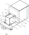
- The subject matter of the present disclosure is now to be explained in more detail by means of selected exemplary embodiments shown in the accompanying drawings. The figures show
- Fig. 1
- a balance comprising a draft shield of the above discussed type;
- Fig. 2
- an embodiment of a draft shield of the above discussed type, comprising two doors which are open;
- Fig. 3
- the draft shield of
figure 2 with the doors closed; - Fig. 4
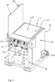
- the draft shield of figured 2 and 3 in a view from a back side, with a first door open and a second door closed;
- Fig. 5
- a detail view of a lock- and release mechanism adapted and configured to hold a door in the closed position with a tensioned spring of a drive mechanism; and
- Fig. 6
- The detail view of
figure 5 with the door fixed in the closed position with a tensioned spring of a drive mechanism. - It is understood that the drawings may be highly schematic, and details not required for instruction purposes may have been omitted for the ease of understanding and depiction. It is further understood that the drawings show only selected, illustrative embodiments, and embodiments not shown may still be well within the scope of the herein disclosed and/or claimed subject matter.
-
-
Figure 1 shows an exemplary embodiment of a balance 1 which is equipped with adraft shield 2 of any type outlined above. Balance 1 is a so-called front loader balance in which the weighing cell is provided withinhousing 11, which further contains electronics for power supply, data processing, and so forth, while the weighing pan on which a weighing good may be placed for weight determination is suspended in front ofhousing 11 and functionally connected to the weighing cell insidehousing 11.Draft shield 2 is placed in front ofhousing 11, onbase 12. In a manner familiar to the person skilled in the art,draft shield 2 covers a weighing pan of the balance and, optionally, other devices required to handle weighing goods and weights inside a weighing chamber defined insidedraft shield 2.Draft shield 2 comprisesframe 29. A first wall ortop wall 21 ofdraft shield 2 comprises a part offrame 29 and atransparent window 215 inserted intoframe 29. A second wall orfront wall 22 ofdraft shield 2 adjoins a front edge oftop wall 21.Front wall 22 may in particular be a transparent wall.Draft shield 2 further comprisesdoors draft shield 2. Each ofdoors Doors axis 25, wherein the swiveling movement takes place in the plane of the respective door. That is, in other words,axis 25 is perpendicular to each ofdoors doors release mechanism 26 is provided to lockdoors release mechanism 26 is outlined in more detail below. -
Figure 2 showsdraft shield 2 withdoors Top wall 21 has afirst edge 211 on the side offirst door 23 and asecond edge 212 on the side ofsecond door 24. Likewise,front wall 22 has afirst edge 221 on the side offirst door 23 and asecond edge 222 on the side ofsecond door 24. As can be seen,first door 23, in the shown open position, is adjacent to, or adjoins,first edge 211 oftop wall 21 and is distant fromfirst edge 221 offront wall 22. Likewise, as the skilled person will readily appreciate,second door 24, in the open position, is adjacent, or adjoins,second edge 212 oftop wall 21 and is distant fromsecond edge 222 offront wall 22. As is outlined in more detail below,swivel axis 25 of each of thedoors doors Handles close doors Figure 3 showsdraft shield 2 withdoors figure 3 in combination with the depiction offigure 2 , in the closed positionfirst door 23 is adjacent to, or adjoins,first edge 211 oftop wall 21 as well asfirst edge 221 offront wall 22. Likewise,second door 24, in the closed position, adjoinssecond edge 212 oftop wall 21 andsecond edge 222 offront wall 22. Further, as will become apparent by the description below,doors release mechanism 26 and may be released by pressing a respective one ofrelease buttons draft sheet 2 comprises drive mechanisms which drive a respective one ofdoors release buttons figures 2 and3 , thatdoors swivel axis 25. -
Figure 4 shows a back view ofdraft shield 2. Combined bearing and driveassemblies top wall 21, and more in particular to a respective section offrame 29. Although not explicitly shown, it is apparent to a person having skill in the art how the shafts providing the swivel axis ofdoors assemblies assembly 27 comprisescoil spring 271.Coil spring 271 is mounted inside bearing and driveassembly 27 and functionally coupled to the shaft connected to door 23 such thatcoil spring 271 is tensioned upon swivelingdoor 23 from the open position towards the closed position. Thus, when releasingdoor 23 in the closed position, or in any position between the closed position in the open position,coil spring 271 drivesdoor 23 towards the open position.Coil spring 271 is further mounted such thatcoil spring 271 remains tensioned whendoor 23 is in the open position so as to securely holddoor 23 in the open position. Bearing and driveassembly 27 further comprisesrotation brake 272, which is adapted and configured in functional connection with the shaft connected to door 23 to retard the swiveling motion ofdoor 23 from the closed position to the open position, driven bycoil spring 271. The function ofrotation brake 272 may in particular be based upon fluid friction and effects a smooth movement ofdoor 23 to the open position. Bearing and driveassembly 28 has the same functionality in connection with second door 24: Bearing and driveassembly 28 supports a shaft, which is not explicitly shown, but is familiar to a skilled person, which is connected tosecond door 24. Bearing and driveassembly 28 comprisescoil spring 281.Coil spring 281 is mounted inside bearing and driveassembly 28 and is functionally coupled to the shaft connected to door 24 such thatcoil spring 281 is tensioned upon swivelingdoor 24 from the open position towards the closed position. Thus, when releasingdoor 24 in the closed position, or in any position between the closed position in the open position,coil spring 281 drivesdoor 24 towards the open position.Coil spring 281 is further mounted such that coil spring remains tensioned whendoor 24 is in the open position so as to securely holddoor 24 in the open position. Bearing and driveassembly 28 further comprisesrotation brake 282, which is adapted and configured in functional connection with the shaft connected to door 28 to retard the swiveling motion ofdoor 24 from the closed position to the open position, driven bycoil spring 281. The function ofrotation brake 282 may in particular be based upon fluid friction and effects a smooth movement ofdoor 24 to the open position. -
Figures 5 and 6 outlined details and function of lock- andrelease mechanism 26. Lock- andrelease mechanism 26 comprisesrelease button 261 andspring 263. For one instance,release button 261 may be made from plastic, whilespring 263 may in particular be a metal spring.Figure 5 showsdoor 23 in a position which would be immediately before locking when movingdoor 23 towards the closed position. The lower corner ofdoor 23 adjacent lock- andrelease mechanism 26 comprises achamfer 232. When swivelingdoor 23 further towards the closed position, i.e., counter-clockwise in the shown depiction,chamfer 232 will make contact with an edge ofrelease button 261 andspring 263. Due to the sloped geometry ofchamfer 232,release button 261 will be displaced by elastic deformation of lock- andrelease mechanism 26, andfurther spring 263 will be elastically deformed. With reference tofigure 6 ,door 23 is shown in the closed position. The restoring force ofspring 263 effects a friction lock ofdoor 23 in the closed position.Spring 263 can be deformed by exerting pressure onrelease button 261, thereby releasingdoor 23. Whendoor 23 is released, bearing and driveassembly 27, cf.figure 4 , will automatically drivedoor 23 to the open position, that is, clockwise in the current depiction. Thus, a convenient semi- automatic door drive mechanism is provided. - While the subject matter of the disclosure has been explained by means of exemplary embodiments, it is understood that these are in no way intended to limit the scope of the claimed invention. It will be appreciated that the claims cover embodiments not explicitly shown or disclosed herein, and embodiments deviating from those disclosed in the exemplary modes of carrying out the teaching of the present disclosure will still be covered by the claims.
-
- 1
- Balance
- 2
- Draft shield
- 11
- Housing of balance
- 12
- Base of balance
- 21
- Top wall of draft shield
- 22
- Front wall of draft shield
- 23
- Door of draft shield
- 24
- Door of draft shield
- 25
- Swivel axis of door of draft shield
- 26
- Lock-and release mechanism
- 27
- Combined bearing and drive assembly
- 28
- Combined bearing and drive assembly
- 29
- Frame of draft shield
- 211
- Edge of top wall
- 212
- Edge of top wall
- 215
- Window
- 221
- Edge of front wall
- 222
- Edge of front wall
- 231
- Handle
- 232
- Chamfered corner of door
- 241
- Handle
- 261
- Release button
- 262
- Release button
- 263
- Spring
- 271
- Coil spring
- 272
- Rotation brake
- 281
- Coil spring
- 282
- Rotation brake
Claims (15)
- A draft shield (2) for a balance (1), the draft shield comprising a first wall (21), a second wall (22) and at least a first door (23), wherein the first wall and the second wall adjoin each other perpendicularly and the first door (23) is provided perpendicular to each of the first wall (21) and the second wall (22), wherein the first door is arranged and configured to swivel between a closed position and an open position, wherein in the closed position the first door adjoins a first edge (211) of the first wall (21) and a first edge (221) of the second wall (22), wherein a swivel axis (25) of the first door extends perpendicular to a face of the first door such that the first door is configured to swivel in the plane of the first door.
- The draft shield according to the preceding claim, wherein in the open position the first door adjoins (23) the first edge (211) of the first wall (21) while being distant to at least a part of the first edge (221) of the second wall (22).
- The draft shield according to any preceding claim, wherein the first door (23) is configured to swivel 80° or more and 100° or less around its swivel axis (25).
- The draft shield according to any preceding claim, wherein the swivel axis (25) of the first door (23) is provided by the axis of a first shaft.
- The draft shield according to the preceding claim, wherein the first shaft is supported in a bearing assembly (27) of the first shaft, wherein in particular said bearing assembly (27) of the first shaft is attached to the first wall (21).
- The draft shield according to the preceding claim, wherein the bearing assembly (27) of the first shaft comprises a drive mechanism (271) which is adapted and configured to drive the swivel movement of the first door (23) in at least one swivel direction.
- The draft shield according to any of claims 4 through 6, wherein the first shaft connects to the first door adjacent a corner of the first door.
- The draft shield (2) according to any preceding claim, wherein the draft shield comprises a second door (24) on an opposite side of the draft shield than the first door (23), wherein the second door (24) is arranged and configured to swivel between a closed position and an open position, wherein in the closed position the second door (24) adjoins a second edge (212) of the first wall (21) and a second edge (222) of the second wall (22), wherein a swivel axis (25) of the second door extends perpendicular to the face of the second door such that the second door is configured to swivel in a plane of the second door,
wherein the swivel axis of the second door is parallel to the swivel axis of the first door. - The draft shield according to the preceding claim, wherein the swivel axis (25) of the first door (23) and the swivel axis of the second door (24) are parallel to each other or in particular are identical.
- The draft shield according to any of claims 8 or 9, wherein in the open position the second door (24) adjoins the second edge (221) of the first wall (21) while being distant to at least a part of the second edge (222) of the second wall (22).
- The draft shield according to any of claims 8 through 10, wherein the second door (24) is configured to swivel 80° or more and 100° or less around its swivel axis (25).
- The draft shield according to any of claims 8 through 11, wherein the swivel axis (25) of the second door (24) is provided by the axis of a second shaft.
- The draft shield according to any of claims 8 through 12, wherein the second shaft is supported in a bearing assembly (28) of the second shaft, wherein in particular the bearing assembly (28) of the second shaft is attached to the first wall (21)..
- The draft shield according to the preceding claim, wherein the bearing assembly (28) of the second shaft comprises a drive mechanism (281) which is adapted and configured to drive the swivel movement of the second door in at least one swivel direction.
- The draft shield according to any of claims 8 through 14, wherein the second shaft connects to the second door (24) adjacent a corner of the second door.
Priority Applications (4)
| Application Number | Priority Date | Filing Date | Title |
|---|---|---|---|
| EP23166631.4A EP4443116B1 (en) | 2023-04-04 | 2023-04-04 | Draft shield comprising a swiveling door |
| PL23166631.4T PL4443116T3 (en) | 2023-04-04 | 2023-04-04 | Draft shield comprising a swiveling door |
| US18/616,348 US12618706B2 (en) | 2023-04-04 | 2024-03-26 | Draft shield comprising a swiveling door |
| CN202410400138.4A CN118776652A (en) | 2023-04-04 | 2024-04-03 | Including draft shield for revolving door |
Applications Claiming Priority (1)
| Application Number | Priority Date | Filing Date | Title |
|---|---|---|---|
| EP23166631.4A EP4443116B1 (en) | 2023-04-04 | 2023-04-04 | Draft shield comprising a swiveling door |
Publications (2)
| Publication Number | Publication Date |
|---|---|
| EP4443116A1 true EP4443116A1 (en) | 2024-10-09 |
| EP4443116B1 EP4443116B1 (en) | 2025-11-26 |
Family
ID=85873591
Family Applications (1)
| Application Number | Title | Priority Date | Filing Date |
|---|---|---|---|
| EP23166631.4A Active EP4443116B1 (en) | 2023-04-04 | 2023-04-04 | Draft shield comprising a swiveling door |
Country Status (4)
| Country | Link |
|---|---|
| US (1) | US12618706B2 (en) |
| EP (1) | EP4443116B1 (en) |
| CN (1) | CN118776652A (en) |
| PL (1) | PL4443116T3 (en) |
Citations (3)
| Publication number | Priority date | Publication date | Assignee | Title |
|---|---|---|---|---|
| EP2060885A1 (en) * | 2007-11-19 | 2009-05-20 | Mettler-Toledo AG | Laboratory device with a protected work chamber |
| EP3557200A1 (en) * | 2018-04-17 | 2019-10-23 | Mettler-Toledo GmbH | Laboratory balance with a motorized draft shield |
| CN215003879U (en) * | 2021-03-29 | 2021-12-03 | 孙志磊 | Electronic balance for chemistry |
Family Cites Families (14)
| Publication number | Priority date | Publication date | Assignee | Title |
|---|---|---|---|---|
| JP2513580Y2 (en) * | 1992-01-31 | 1996-10-09 | 株式会社島津製作所 | Balance with windshield |
| DE10214954C1 (en) * | 2002-04-04 | 2003-09-04 | Mettler Toledo Gmbh | Precision weighing device with wind shield having sliding walls for opening and closing weighing chamber operated via pairs of grip elements |
| EP1367372B1 (en) * | 2002-05-29 | 2005-11-23 | Mettler-Toledo GmbH | Wind protection device for a balance and balance with a wind protection device |
| JP2004219314A (en) * | 2003-01-16 | 2004-08-05 | Shinko Denshi Kk | Scale windshield |
| DE10330788A1 (en) * | 2003-07-07 | 2005-02-10 | Mettler-Toledo Gmbh | Libra with windbreak element |
| DE102007058330C5 (en) * | 2007-12-04 | 2014-05-08 | Sartorius Lab Instruments Gmbh & Co. Kg | Libra |
| PL223292B1 (en) * | 2012-09-10 | 2016-10-31 | Lewandowski Witold Radwag Wagi Elektroniczne | Mechanism of automatic door opening for the weighing chamber of an analytical balance |
| DE102013113003A1 (en) * | 2013-11-25 | 2015-05-28 | Sartorius Lab Instruments Gmbh & Co. Kg | Weighing room floor and draft shield for a precision balance and precision balance |
| DE102013112998B4 (en) * | 2013-11-25 | 2021-10-21 | Sartorius Lab Instruments Gmbh & Co. Kg | Cover of a draft shield of a precision balance and a draft shield for a precision balance |
| EP2924401B1 (en) * | 2014-03-28 | 2016-12-28 | Mettler-Toledo GmbH | Robot-actuated door-opening device for a draft protection housing of an analytical scale |
| PL3557199T3 (en) * | 2018-04-17 | 2021-05-31 | Mettler-Toledo Gmbh | Laboratory balance with a weighing chamber rear wall of modular construction |
| EP3578935B1 (en) * | 2018-06-07 | 2021-03-31 | Mettler-Toledo GmbH | A weighing device with a movable mounting unit |
| PL3705858T3 (en) * | 2019-03-07 | 2022-01-31 | Mettler-Toledo Gmbh | A weighing balance having a mounting unit for carrying replacable accessories |
| EP3705856B1 (en) * | 2019-03-07 | 2022-11-16 | Mettler-Toledo GmbH | A drive device used in combination with a weighing balance |
-
2023
- 2023-04-04 PL PL23166631.4T patent/PL4443116T3/en unknown
- 2023-04-04 EP EP23166631.4A patent/EP4443116B1/en active Active
-
2024
- 2024-03-26 US US18/616,348 patent/US12618706B2/en active Active
- 2024-04-03 CN CN202410400138.4A patent/CN118776652A/en active Pending
Patent Citations (3)
| Publication number | Priority date | Publication date | Assignee | Title |
|---|---|---|---|---|
| EP2060885A1 (en) * | 2007-11-19 | 2009-05-20 | Mettler-Toledo AG | Laboratory device with a protected work chamber |
| EP3557200A1 (en) * | 2018-04-17 | 2019-10-23 | Mettler-Toledo GmbH | Laboratory balance with a motorized draft shield |
| CN215003879U (en) * | 2021-03-29 | 2021-12-03 | 孙志磊 | Electronic balance for chemistry |
Also Published As
| Publication number | Publication date |
|---|---|
| PL4443116T3 (en) | 2026-02-23 |
| CN118776652A (en) | 2024-10-15 |
| US20240337524A1 (en) | 2024-10-10 |
| EP4443116B1 (en) | 2025-11-26 |
| US12618706B2 (en) | 2026-05-05 |
Similar Documents
| Publication | Publication Date | Title |
|---|---|---|
| CN116157639A (en) | Hinge structure of refrigerator | |
| US6086121A (en) | Rod roller system for multi-point latch | |
| CN101675324B (en) | Detachable windshield for weighing device | |
| JP5062879B2 (en) | Windshield for weighing device | |
| EP2613115A2 (en) | Latch and refrigerator having the same | |
| CN110388978B (en) | Laboratory weighing device with motorized windshield | |
| EP4624875B1 (en) | Electronic balance | |
| EP4443116B1 (en) | Draft shield comprising a swiveling door | |
| US7934292B2 (en) | Hinge mechanism | |
| US8147008B2 (en) | Interlock system for multi-door enclosures | |
| US20100072038A1 (en) | Dust Buildup Resistant Access Door and Door Frame of a Bulk Material Handling System | |
| US20060284064A1 (en) | Door assembly for a semi-automatic micro-hole plate single-photon counter | |
| US7275770B2 (en) | Interlock system for enclosures | |
| US20210309030A1 (en) | Hinge assembly | |
| CN221125312U (en) | Outdoor locker | |
| CN210127758U (en) | Electric hatch assembly and robot | |
| CN222649833U (en) | Automatic door and detection equipment | |
| CN214217009U (en) | Bucket rotating shaft structure not easy to leave dirt | |
| JP7595924B2 (en) | Water Stop Unit | |
| CN223433474U (en) | Microorganism detector | |
| EP3848914B1 (en) | An alarm assembly | |
| CN216140459U (en) | Input box and slide glass writing instrument comprising same | |
| JPH0530738U (en) | Windshield for weighing device | |
| JPH0611560Y2 (en) | Case door mounting structure | |
| JP4855294B2 (en) | Upper door opening / closing structure of windshield for weighing device |
Legal Events
| Date | Code | Title | Description |
|---|---|---|---|
| PUAI | Public reference made under article 153(3) epc to a published international application that has entered the european phase |
Free format text: ORIGINAL CODE: 0009012 |
|
| STAA | Information on the status of an ep patent application or granted ep patent |
Free format text: STATUS: THE APPLICATION HAS BEEN PUBLISHED |
|
| AK | Designated contracting states |
Kind code of ref document: A1 Designated state(s): AL AT BE BG CH CY CZ DE DK EE ES FI FR GB GR HR HU IE IS IT LI LT LU LV MC ME MK MT NL NO PL PT RO RS SE SI SK SM TR |
|
| STAA | Information on the status of an ep patent application or granted ep patent |
Free format text: STATUS: REQUEST FOR EXAMINATION WAS MADE |
|
| 17P | Request for examination filed |
Effective date: 20250227 |
|
| GRAP | Despatch of communication of intention to grant a patent |
Free format text: ORIGINAL CODE: EPIDOSNIGR1 |
|
| STAA | Information on the status of an ep patent application or granted ep patent |
Free format text: STATUS: GRANT OF PATENT IS INTENDED |
|
| RIC1 | Information provided on ipc code assigned before grant |
Ipc: G01G 21/28 20060101AFI20250617BHEP |
|
| INTG | Intention to grant announced |
Effective date: 20250701 |
|
| GRAS | Grant fee paid |
Free format text: ORIGINAL CODE: EPIDOSNIGR3 |
|
| GRAA | (expected) grant |
Free format text: ORIGINAL CODE: 0009210 |
|
| STAA | Information on the status of an ep patent application or granted ep patent |
Free format text: STATUS: THE PATENT HAS BEEN GRANTED |
|
| AK | Designated contracting states |
Kind code of ref document: B1 Designated state(s): AL AT BE BG CH CY CZ DE DK EE ES FI FR GB GR HR HU IE IS IT LI LT LU LV MC ME MK MT NL NO PL PT RO RS SE SI SK SM TR |
|
| REG | Reference to a national code |
Ref country code: CH Ref legal event code: F10 Free format text: ST27 STATUS EVENT CODE: U-0-0-F10-F00 (AS PROVIDED BY THE NATIONAL OFFICE) Effective date: 20251126 Ref country code: GB Ref legal event code: FG4D |
|
| REG | Reference to a national code |
Ref country code: IE Ref legal event code: FG4D |
|
| REG | Reference to a national code |
Ref country code: DE Ref legal event code: R096 Ref document number: 602023008886 Country of ref document: DE |
|
| REG | Reference to a national code |
Ref country code: NL Ref legal event code: MP Effective date: 20251126 |
|
| PG25 | Lapsed in a contracting state [announced via postgrant information from national office to epo] |
Ref country code: ES Free format text: LAPSE BECAUSE OF FAILURE TO SUBMIT A TRANSLATION OF THE DESCRIPTION OR TO PAY THE FEE WITHIN THE PRESCRIBED TIME-LIMIT Effective date: 20251126 |
|
| REG | Reference to a national code |
Ref country code: LT Ref legal event code: MG9D |
|
| PG25 | Lapsed in a contracting state [announced via postgrant information from national office to epo] |
Ref country code: NO Free format text: LAPSE BECAUSE OF FAILURE TO SUBMIT A TRANSLATION OF THE DESCRIPTION OR TO PAY THE FEE WITHIN THE PRESCRIBED TIME-LIMIT Effective date: 20260226 |
|
| PG25 | Lapsed in a contracting state [announced via postgrant information from national office to epo] |
Ref country code: FI Free format text: LAPSE BECAUSE OF FAILURE TO SUBMIT A TRANSLATION OF THE DESCRIPTION OR TO PAY THE FEE WITHIN THE PRESCRIBED TIME-LIMIT Effective date: 20251126 Ref country code: HR Free format text: LAPSE BECAUSE OF FAILURE TO SUBMIT A TRANSLATION OF THE DESCRIPTION OR TO PAY THE FEE WITHIN THE PRESCRIBED TIME-LIMIT Effective date: 20251126 Ref country code: AT Free format text: LAPSE BECAUSE OF FAILURE TO SUBMIT A TRANSLATION OF THE DESCRIPTION OR TO PAY THE FEE WITHIN THE PRESCRIBED TIME-LIMIT Effective date: 20251126 |
|
| REG | Reference to a national code |
Ref country code: AT Ref legal event code: MK05 Ref document number: 1861470 Country of ref document: AT Kind code of ref document: T Effective date: 20251126 |
|
| PG25 | Lapsed in a contracting state [announced via postgrant information from national office to epo] |
Ref country code: NL Free format text: LAPSE BECAUSE OF FAILURE TO SUBMIT A TRANSLATION OF THE DESCRIPTION OR TO PAY THE FEE WITHIN THE PRESCRIBED TIME-LIMIT Effective date: 20251126 |
|
| PG25 | Lapsed in a contracting state [announced via postgrant information from national office to epo] |
Ref country code: RS Free format text: LAPSE BECAUSE OF FAILURE TO SUBMIT A TRANSLATION OF THE DESCRIPTION OR TO PAY THE FEE WITHIN THE PRESCRIBED TIME-LIMIT Effective date: 20260226 |
|
| PG25 | Lapsed in a contracting state [announced via postgrant information from national office to epo] |
Ref country code: IS Free format text: LAPSE BECAUSE OF FAILURE TO SUBMIT A TRANSLATION OF THE DESCRIPTION OR TO PAY THE FEE WITHIN THE PRESCRIBED TIME-LIMIT Effective date: 20260326 |
|
| PG25 | Lapsed in a contracting state [announced via postgrant information from national office to epo] |
Ref country code: PT Free format text: LAPSE BECAUSE OF FAILURE TO SUBMIT A TRANSLATION OF THE DESCRIPTION OR TO PAY THE FEE WITHIN THE PRESCRIBED TIME-LIMIT Effective date: 20260326 |
|
| PGFP | Annual fee paid to national office [announced via postgrant information from national office to epo] |
Ref country code: PL Payment date: 20260316 Year of fee payment: 4 |
|
| PG25 | Lapsed in a contracting state [announced via postgrant information from national office to epo] |
Ref country code: LV Free format text: LAPSE BECAUSE OF FAILURE TO SUBMIT A TRANSLATION OF THE DESCRIPTION OR TO PAY THE FEE WITHIN THE PRESCRIBED TIME-LIMIT Effective date: 20251126 |
|
| PG25 | Lapsed in a contracting state [announced via postgrant information from national office to epo] |
Ref country code: BG Free format text: LAPSE BECAUSE OF FAILURE TO SUBMIT A TRANSLATION OF THE DESCRIPTION OR TO PAY THE FEE WITHIN THE PRESCRIBED TIME-LIMIT Effective date: 20251126 |
|
| REG | Reference to a national code |
Ref country code: CH Ref legal event code: U11 Free format text: ST27 STATUS EVENT CODE: U-0-0-U10-U11 (AS PROVIDED BY THE NATIONAL OFFICE) Effective date: 20260501 |