EP4443018A1 - Variable gear ratio transfer gear set for actuation system - Google Patents
Variable gear ratio transfer gear set for actuation system Download PDFInfo
- Publication number
- EP4443018A1 EP4443018A1 EP24167039.7A EP24167039A EP4443018A1 EP 4443018 A1 EP4443018 A1 EP 4443018A1 EP 24167039 A EP24167039 A EP 24167039A EP 4443018 A1 EP4443018 A1 EP 4443018A1
- Authority
- EP
- European Patent Office
- Prior art keywords
- gear
- gear set
- component
- gear ratio
- ring
- Prior art date
- Legal status (The legal status is an assumption and is not a legal conclusion. Google has not performed a legal analysis and makes no representation as to the accuracy of the status listed.)
- Pending
Links
Images


Classifications
-
- F—MECHANICAL ENGINEERING; LIGHTING; HEATING; WEAPONS; BLASTING
- F16—ENGINEERING ELEMENTS AND UNITS; GENERAL MEASURES FOR PRODUCING AND MAINTAINING EFFECTIVE FUNCTIONING OF MACHINES OR INSTALLATIONS; THERMAL INSULATION IN GENERAL
- F16H—GEARING
- F16H3/00—Toothed gearings for conveying rotary motion with variable gear ratio or for reversing rotary motion
- F16H3/003—Toothed gearings for conveying rotary motion with variable gear ratio or for reversing rotary motion the gear ratio being changed by inversion of torque direction
- F16H3/005—Toothed gearings for conveying rotary motion with variable gear ratio or for reversing rotary motion the gear ratio being changed by inversion of torque direction for gearings using gears having orbital motion
-
- B—PERFORMING OPERATIONS; TRANSPORTING
- B64—AIRCRAFT; AVIATION; COSMONAUTICS
- B64C—AEROPLANES; HELICOPTERS
- B64C13/00—Control systems or transmitting systems for actuating flying-control surfaces, lift-increasing flaps, air brakes, or spoilers
- B64C13/24—Transmitting means
- B64C13/26—Transmitting means without power amplification or where power amplification is irrelevant
- B64C13/28—Transmitting means without power amplification or where power amplification is irrelevant mechanical
- B64C13/34—Transmitting means without power amplification or where power amplification is irrelevant mechanical using toothed gearing
-
- F—MECHANICAL ENGINEERING; LIGHTING; HEATING; WEAPONS; BLASTING
- F16—ENGINEERING ELEMENTS AND UNITS; GENERAL MEASURES FOR PRODUCING AND MAINTAINING EFFECTIVE FUNCTIONING OF MACHINES OR INSTALLATIONS; THERMAL INSULATION IN GENERAL
- F16D—COUPLINGS FOR TRANSMITTING ROTATION; CLUTCHES; BRAKES
- F16D41/00—Freewheels or freewheel clutches
- F16D41/06—Freewheels or freewheel clutches with intermediate wedging coupling members between an inner and an outer surface
- F16D41/064—Freewheels or freewheel clutches with intermediate wedging coupling members between an inner and an outer surface the intermediate members wedging by rolling and having a circular cross-section, e.g. balls
- F16D41/066—Freewheels or freewheel clutches with intermediate wedging coupling members between an inner and an outer surface the intermediate members wedging by rolling and having a circular cross-section, e.g. balls all members having the same size and only one of the two surfaces being cylindrical
-
- F—MECHANICAL ENGINEERING; LIGHTING; HEATING; WEAPONS; BLASTING
- F16—ENGINEERING ELEMENTS AND UNITS; GENERAL MEASURES FOR PRODUCING AND MAINTAINING EFFECTIVE FUNCTIONING OF MACHINES OR INSTALLATIONS; THERMAL INSULATION IN GENERAL
- F16H—GEARING
- F16H25/00—Gearings comprising primarily only cams, cam-followers and screw-and-nut mechanisms
- F16H25/18—Gearings comprising primarily only cams, cam-followers and screw-and-nut mechanisms for conveying or interconverting oscillating or reciprocating motions
- F16H25/20—Screw mechanisms
-
- F—MECHANICAL ENGINEERING; LIGHTING; HEATING; WEAPONS; BLASTING
- F16—ENGINEERING ELEMENTS AND UNITS; GENERAL MEASURES FOR PRODUCING AND MAINTAINING EFFECTIVE FUNCTIONING OF MACHINES OR INSTALLATIONS; THERMAL INSULATION IN GENERAL
- F16H—GEARING
- F16H25/00—Gearings comprising primarily only cams, cam-followers and screw-and-nut mechanisms
- F16H25/18—Gearings comprising primarily only cams, cam-followers and screw-and-nut mechanisms for conveying or interconverting oscillating or reciprocating motions
- F16H25/20—Screw mechanisms
- F16H2025/2062—Arrangements for driving the actuator
- F16H2025/2075—Coaxial drive motors
-
- F—MECHANICAL ENGINEERING; LIGHTING; HEATING; WEAPONS; BLASTING
- F16—ENGINEERING ELEMENTS AND UNITS; GENERAL MEASURES FOR PRODUCING AND MAINTAINING EFFECTIVE FUNCTIONING OF MACHINES OR INSTALLATIONS; THERMAL INSULATION IN GENERAL
- F16H—GEARING
- F16H25/00—Gearings comprising primarily only cams, cam-followers and screw-and-nut mechanisms
- F16H25/18—Gearings comprising primarily only cams, cam-followers and screw-and-nut mechanisms for conveying or interconverting oscillating or reciprocating motions
- F16H25/20—Screw mechanisms
- F16H2025/2062—Arrangements for driving the actuator
- F16H2025/2087—Arrangements for driving the actuator using planetary gears
Definitions
- Exemplary embodiments pertain to the art of actuator systems, and in particular to torque transfer gear sets for actuation systems.
- the actuator has different torque and stroke time requirements for an extension stroke and for a retraction stroke. This difference is torque and stroke time requirements for the opposing strokes leads to the actuator and the gear set being sized for the maximum torque and stroke time requirements, and thus oversizing of the system to handle those requirements.
- a variable gear ratio gear set system includes a planetary gear set including a sun gear locate at a central axis of rotation, a plurality of planet gears meshed with the sun gear and retained at a carrier, and a ring gear surrounding the plurality of planet gears and meshed therewith.
- An input shaft inputs rotational energy to the planetary gear set at a first rotational speed, and an output shaft outputs rotational energy from the planetary gear set at a second rotational speed.
- a plurality of one-way clutches are positioned in the gear set and are engageable such that the system has a first gear ratio when the input shaft is rotated in a first direction, and a second gear ratio when the input shaft is rotated in a second direction.
- a first one-way clutch of the plurality of one-way clutches is operably coupled to the ring gear and the output shaft.
- a second one-way clutch of the plurality of one-way clutches is operably coupled to the carrier and the output shaft.
- a third one-way clutch of the plurality of one-way clutches is operably coupled to the ring gear and a ground.
- a fourth one-way clutch of the plurality of one-way clutches is operably coupled to the carrier and a ground.
- each of the one-way clutches of the plurality of one-way clutches includes a ramp located at a first component, a ring located at a second component, and a roller located between the ramp and the ring, such that during rotation of the first component in a first rotation direction urges the roller up the ramp to jam between the ramp and the ring preventing rotation of the first component relative to the second component, and rotation of the first component in a second rotation direction there is free rotation of the first component relative to the second component.
- a torque transmission path is through the sun gear, through the carrier and through the output shaft.
- the ring gear is rotationally fixed.
- a torque transmission path is through the sun gear, through the plurality of planet gears, through the ring gear and through the output shaft.
- the carrier is rotationally fixed.
- an actuation system in another aspect, includes an actuator configured to drive movement of a component coupled to the actuator, a power source operably coupled to the actuator to drive operation of the actuator, and a variable gear ratio gear set system.
- the variable gear ratio gear set system includes a planetary gear set including a sun gear located at a central axis of rotation, a plurality of planet gears meshed with the sun gear and retained at a carrier, and a ring gear surrounding the plurality of planet gears and meshed therewith.
- An input shaft is operably connected to the power source to input rotational energy to the planetary gear set at a first rotational speed, and an output shaft outputs rotational energy from the planetary gear set to the actuator at a second rotational speed.
- a plurality of one-way clutches are positioned in the gear set and are engageable such that the system has a first gear ratio when the input shaft is rotated in a first direction, and a second gear ratio when the input shaft is rotated in a second direction.
- a first one-way clutch of the plurality of one-way clutches is operably coupled to the ring gear and the output shaft.
- a second one-way clutch of the plurality of one-way clutches is operably coupled to the carrier and the output shaft.
- a third one-way clutch of the plurality of one-way clutches is operably coupled to the ring gear and a ground.
- a fourth one-way clutch of the plurality of one-way clutches is operably coupled to the carrier and a ground.
- each of the one-way clutches of the plurality of one-way clutches includes a ramp located at a first component, a ring located at a second component, and a roller located between the ramp and the ring, such that during rotation of the first component in a first rotation direction urges the roller up the ramp to jam between the ramp and the ring preventing rotation of the first component relative to the second component, and rotation of the first component in a second rotation direction there is free rotation of the first component relative to the second component.
- a torque transmission path is through the sun gear, through the carrier and through the output shaft.
- the ring gear is fixed.
- a torque transmission path is through the sun gear, through the plurality of planet gears, through the ring gear and through the output shaft.
- the actuator is a screw nut driven actuator.
- the actuation system 10 includes an actuator 12, in one embodiment a screw-nut driven actuator 12.
- the actuator 12 includes a screw 14 that inputs torque into the actuator 12 and a nut 16 that reacts the torque to effect movement of a driven component, such as a control surface 18 or the like.
- the actuator 12 is driven by a power source 20, such as a motor or the like.
- the power source 20 drives rotation of an input shaft 22 at a first speed, which is connected to a transfer gear set 24.
- the transfer gear set 24 modifies a rotational speed of the energy from the input shaft 22 and outputs the rotational energy at a second speed along an output shaft 26.
- the output shaft 26 is operably connected to the screw 14 to drove the actuator 12.
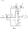
- the transfer gear set 24 is a planetary gear set.
- the transfer gear set 24 includes a sun gear 28 operably connected to the input shaft 22, and in some embodiments shares a common axis of rotation 30 with the input shaft 22.
- a plurality of planet gears 32 are supported by a carrier 34 and are meshed with the sun gear 28 such that rotation of the sun gear 28 about its axis of rotation 30 urges rotation of each of the planet gears 32 about their respective planet axes of rotation 36.
- a ring gear 38 surrounds the plurality of planet gears 32 and is meshed with the planet gears 32.
- the output shaft 26 extends from the transfer gear set 24 and is driven about the axis of rotation 30 by one of the ring gear 38 or the carrier 34, as will be explained further.
- the transfer gear set 24 further includes a plurality of one-way clutches.
- a first one-way clutch 40a is disposed between the ring gear 38 and the output shaft 26, and interconnects the ring gear 38 and the output shaft 26.
- a second one-way clutch 40b is disposed between the carrier 34 and the output shaft 26, and interconnects the carrier 34 and the output shaft 26.
- a third one-way clutch 40c is disposed between the ring gear 38 and ground, such as a housing 42 and interconnects the ring gear 38 and the housing 42.
- a fourth one-way clutch 40d is disposed between the carrier 34 and the housing 42, and interconnects the carrier 34 and the housing 42.
- FIG. 3 An illustration of an exemplary one-way clutch 40 is shown in FIG. 3 .
- the clutch 40 includes a ramp 44 disposed at a first component 46, and a ring 48 at a second component 50.
- a clutch element such as a roller 52, a ball, or a pin is disposed on the ramp 44 between the first component 46 and the second component 50.
- the roller 52 travels up the ramp 44 until the roller 52 jams between the ramp 44 and the ring 48 preventing rotation of the first component 46 in the first direction 54.
- FIG. 4 when the first component 46 is rotated in a second direction 56 opposite the first direction 54, the roller 52 does not jam between the ramp 44 and the ring 48, allowing free rotation of the first component 46 in the second direction 56 relative to the second component 50.
- the input shaft 22 is driven in a first input direction, for example, a clockwise direction 58 thus driving the sun gear 28 in the clockwise direction 58.
- a first input direction for example, a clockwise direction 58
- This results in a first gear ratio of 1 + T ring /T sun where T ring and T sun are the number of teeth of the ring gear 38 and the sun gear 28, respectively.
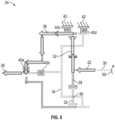
- the sun gear 28 is driven in a second input direction, an anti-clockwise direction 60.
- the torque transfer path is from the sun gear 28, through the plurality of planet gears 32, through the ring gear 38 and through the output shaft 26.
- This results in a second gear ratio of - T ring /T sun where T ring and T sun are the number of teeth of the ring gear 38 and the sun gear 28, respectively.
Landscapes
- Engineering & Computer Science (AREA)
- General Engineering & Computer Science (AREA)
- Mechanical Engineering (AREA)
- Automation & Control Theory (AREA)
- Aviation & Aerospace Engineering (AREA)
- Transmission Devices (AREA)
- Structure Of Transmissions (AREA)
Abstract
A variable gear ratio gear set system includes a planetary gear set (24) including a sun gear (28) locate at a central axis of rotation, a plurality of planet gears (32) meshed with the sun gear and retained at a carrier (34), and a ring gear (38) surrounding the plurality of planet gears and meshed therewith. An input shaft (22) inputs rotational energy to the planetary gear set at a first rotational speed, and an output shaft (26) outputs rotational energy from the planetary gear set at a second rotational speed. A plurality of one-way clutches (40a, 40b, 40c, 40d) are positioned in the gear set and are engageable such that the system has a first gear ratio when the input shaft is rotated in a first direction, and a second gear ratio when the input shaft is rotated in a second direction.
Description
- This application claims the benefit of
Indian Application No. 202311021804 filed March 27, 2023 - Exemplary embodiments pertain to the art of actuator systems, and in particular to torque transfer gear sets for actuation systems.
- In some actuation systems, for example, screw-nut driven compressive loaded actuators, the actuator has different torque and stroke time requirements for an extension stroke and for a retraction stroke. This difference is torque and stroke time requirements for the opposing strokes leads to the actuator and the gear set being sized for the maximum torque and stroke time requirements, and thus oversizing of the system to handle those requirements.
- In one aspect, a variable gear ratio gear set system includes a planetary gear set including a sun gear locate at a central axis of rotation, a plurality of planet gears meshed with the sun gear and retained at a carrier, and a ring gear surrounding the plurality of planet gears and meshed therewith. An input shaft inputs rotational energy to the planetary gear set at a first rotational speed, and an output shaft outputs rotational energy from the planetary gear set at a second rotational speed. A plurality of one-way clutches are positioned in the gear set and are engageable such that the system has a first gear ratio when the input shaft is rotated in a first direction, and a second gear ratio when the input shaft is rotated in a second direction.
- In embodiments, a first one-way clutch of the plurality of one-way clutches is operably coupled to the ring gear and the output shaft.
- In embodiments, a second one-way clutch of the plurality of one-way clutches is operably coupled to the carrier and the output shaft.
- In embodiments, a third one-way clutch of the plurality of one-way clutches is operably coupled to the ring gear and a ground.
- In embodiments, a fourth one-way clutch of the plurality of one-way clutches is operably coupled to the carrier and a ground.
- In embodiments, each of the one-way clutches of the plurality of one-way clutches includes a ramp located at a first component, a ring located at a second component, and a roller located between the ramp and the ring, such that during rotation of the first component in a first rotation direction urges the roller up the ramp to jam between the ramp and the ring preventing rotation of the first component relative to the second component, and rotation of the first component in a second rotation direction there is free rotation of the first component relative to the second component.
- In embodiments, when the input shaft is rotated in the first direction, a torque transmission path is through the sun gear, through the carrier and through the output shaft.
- In embodiments, the ring gear is rotationally fixed.
- In embodiments, when the input shaft is rotated in the second direction, a torque transmission path is through the sun gear, through the plurality of planet gears, through the ring gear and through the output shaft.
- In embodiments, the carrier is rotationally fixed.
- In another aspect, an actuation system includes an actuator configured to drive movement of a component coupled to the actuator, a power source operably coupled to the actuator to drive operation of the actuator, and a variable gear ratio gear set system. The variable gear ratio gear set system includes a planetary gear set including a sun gear located at a central axis of rotation, a plurality of planet gears meshed with the sun gear and retained at a carrier, and a ring gear surrounding the plurality of planet gears and meshed therewith. An input shaft is operably connected to the power source to input rotational energy to the planetary gear set at a first rotational speed, and an output shaft outputs rotational energy from the planetary gear set to the actuator at a second rotational speed. A plurality of one-way clutches are positioned in the gear set and are engageable such that the system has a first gear ratio when the input shaft is rotated in a first direction, and a second gear ratio when the input shaft is rotated in a second direction.
- In embodiments, a first one-way clutch of the plurality of one-way clutches is operably coupled to the ring gear and the output shaft.
- In embodiments, a second one-way clutch of the plurality of one-way clutches is operably coupled to the carrier and the output shaft.
- In embodiments, a third one-way clutch of the plurality of one-way clutches is operably coupled to the ring gear and a ground.
- In embodiments, a fourth one-way clutch of the plurality of one-way clutches is operably coupled to the carrier and a ground.
- In embodiments, each of the one-way clutches of the plurality of one-way clutches includes a ramp located at a first component, a ring located at a second component, and a roller located between the ramp and the ring, such that during rotation of the first component in a first rotation direction urges the roller up the ramp to jam between the ramp and the ring preventing rotation of the first component relative to the second component, and rotation of the first component in a second rotation direction there is free rotation of the first component relative to the second component.
- In embodiments, when the input shaft is rotated in the first direction, a torque transmission path is through the sun gear, through the carrier and through the output shaft.
- In embodiments, the ring gear is fixed.
- In embodiments, when the input shaft is rotated in the second direction, a torque transmission path is through the sun gear, through the plurality of planet gears, through the ring gear and through the output shaft.
- In embodiments, the actuator is a screw nut driven actuator.
- The following descriptions should not be considered limiting in any way. With reference to the accompanying drawings, like elements are numbered alike:
-
FIG. 1 is a schematic illustration of an embodiment of an actuation system; -
FIG. 2 is a schematic illustration of an embodiment of a transfer gear set of an actuation system; -
FIG. 3 is a schematic illustration of an embodiment of a one-way clutch of a transfer gear set; -
FIG. 4 is another schematic illustration of an embodiment of a one-way clutch of a transfer gear set; and -
FIG. 5 is another schematic illustration of an embodiment of a transfer gear set of an actuation system. - A detailed description of one or more embodiments of the disclosed apparatus and method are presented herein by way of exemplification and not limitation with reference to the Figures.
- Referring to
FIG. 1 , illustrated is a schematic illustration of anactuation system 10. Theactuation system 10 includes anactuator 12, in one embodiment a screw-nut drivenactuator 12. Theactuator 12 includes ascrew 14 that inputs torque into theactuator 12 and anut 16 that reacts the torque to effect movement of a driven component, such as acontrol surface 18 or the like. Theactuator 12 is driven by apower source 20, such as a motor or the like. Thepower source 20 drives rotation of aninput shaft 22 at a first speed, which is connected to atransfer gear set 24. Thetransfer gear set 24 modifies a rotational speed of the energy from theinput shaft 22 and outputs the rotational energy at a second speed along anoutput shaft 26. Theoutput shaft 26 is operably connected to thescrew 14 to drove theactuator 12. - Referring now to
FIG. 2 , shown is a schematic illustration of an embodiment of atransfer gear set 24. Thetransfer gear set 24 is a planetary gear set. Thetransfer gear set 24 includes asun gear 28 operably connected to theinput shaft 22, and in some embodiments shares a common axis ofrotation 30 with theinput shaft 22. A plurality ofplanet gears 32 are supported by acarrier 34 and are meshed with thesun gear 28 such that rotation of thesun gear 28 about its axis ofrotation 30 urges rotation of each of theplanet gears 32 about their respective planet axes ofrotation 36. Aring gear 38 surrounds the plurality ofplanet gears 32 and is meshed with theplanet gears 32. Theoutput shaft 26 extends from thetransfer gear set 24 and is driven about the axis ofrotation 30 by one of thering gear 38 or thecarrier 34, as will be explained further. - The transfer gear set 24 further includes a plurality of one-way clutches. A first one-
way clutch 40a is disposed between thering gear 38 and theoutput shaft 26, and interconnects thering gear 38 and theoutput shaft 26. A second one-way clutch 40b is disposed between thecarrier 34 and theoutput shaft 26, and interconnects thecarrier 34 and theoutput shaft 26. A third one-way clutch 40c is disposed between thering gear 38 and ground, such as ahousing 42 and interconnects thering gear 38 and thehousing 42. A fourth one-way clutch 40d is disposed between thecarrier 34 and thehousing 42, and interconnects thecarrier 34 and thehousing 42. - An illustration of an exemplary one-
way clutch 40 is shown inFIG. 3 . Theclutch 40 includes aramp 44 disposed at afirst component 46, and aring 48 at asecond component 50. A clutch element, such as aroller 52, a ball, or a pin is disposed on theramp 44 between thefirst component 46 and thesecond component 50. As illustrated inFIG. 3 , when it is attempted to rotate thefirst component 46 in afirst direction 54, theroller 52 travels up theramp 44 until theroller 52 jams between theramp 44 and thering 48 preventing rotation of thefirst component 46 in thefirst direction 54. Alternatively, as illustrated inFIG. 4 , when thefirst component 46 is rotated in asecond direction 56 opposite thefirst direction 54, theroller 52 does not jam between theramp 44 and thering 48, allowing free rotation of thefirst component 46 in thesecond direction 56 relative to thesecond component 50. - Referring again to
FIG. 2 , operation of the gear set 24 will be described further. InFIG. 2 , theinput shaft 22 is driven in a first input direction, for example, aclockwise direction 58 thus driving thesun gear 28 in theclockwise direction 58. When thesun gear 28 is driven in theclockwise direction 58, this results in a free rotation condition at the first one-way clutch 40a, a jam condition at the second one-way clutch 40b and at the third one-way clutch 40c, and a free rotation condition at the fourth one-way clutch 40d. This results in torque transfer from thesun gear 28 through thecarrier 34 and then through theoutput shaft 26. This results in a first gear ratio of 1 + Tring/Tsun, where Tring and Tsun are the number of teeth of thering gear 38 and thesun gear 28, respectively. - Alternatively, as illustrated in
FIG. 5 , thesun gear 28 is driven in a second input direction, ananti-clockwise direction 60. This results in a jam condition at the first one-way clutch 40a, a free rotation condition at the second one-way clutch 40b and at the third one-way clutch 40c, and a free-rotation condition at the fourth one-way clutch 40d. In this condition, the torque transfer path is from thesun gear 28, through the plurality of planet gears 32, through thering gear 38 and through theoutput shaft 26. This results in a second gear ratio of - Tring/Tsun, where Tring and Tsun are the number of teeth of thering gear 38 and thesun gear 28, respectively. - Use of the one-
way clutches 40 in the way described in the present disclosure, produces different gear ratios from the transfer gear set 24 depending on the direction of rotation of theinput shaft 22 Applied to theactuation system 10, when thepower source 20 drives theinput shaft 22 in a first direction for example, for an extension stroke of theactuator 12, a first gear ratio is utilized. Alternatively, when thepower source 20 drives theinput shaft 22 in the second direction for example, for a retraction stroke of theactuator 12, the second gear ratio is utilized. This allows for tuning or optimizing of the gear ratios of the transfer gear set 24 such that the gear set 24 may be designed for both the extension and retraction stroke requirements, reducing weight and size of theactuation system 10 compared to typical systems. - The term "about" is intended to include the degree of error associated with measurement of the particular quantity based upon the equipment available at the time of filing the application.
- The terminology used herein is for the purpose of describing particular embodiments only and is not intended to be limiting of the present disclosure. As used herein, the singular forms "a", "an" and "the" are intended to include the plural forms as well, unless the context clearly indicates otherwise. It will be further understood that the terms "comprises" and/or "comprising," when used in this specification, specify the presence of stated features, integers, steps, operations, elements, and/or components, but do not preclude the presence or addition of one or more other features, integers, steps, operations, element components, and/or groups thereof.
- While the present disclosure has been described with reference to an exemplary embodiment or embodiments, it will be understood by those skilled in the art that various changes may be made without departing from the scope of the invention as defined by the claims. In addition, many modifications may be made to adapt a particular situation or material to the teachings of the present disclosure without departing from the scope of the claims. Therefore, it is intended that the present disclosure not be limited to the particular embodiment disclosed as the best mode contemplated for carrying out this present disclosure, but that the present disclosure will include all embodiments falling within the scope of the claims.
Claims (12)
- A variable gear ratio gear set system, comprising:
a planetary gear set (24) including:a sun gear (28) disposed at a central axis of rotation;a plurality of planet gears (32) meshed with the sun gear and retained at a carrier (34); anda ring gear (38) surrounding the plurality of planet gears and meshed therewith;an input shaft (22) to input rotational energy to the planetary gear set at a first rotational speed;an output shaft (26) to output rotational energy from the planetary gear set at a second rotational speed;a plurality of one-way clutches (40a, 40b, 40c, 40d) disposed in the gear set and engageable such that the system has a first gear ratio when the input shaft is rotated in a first direction, and a second gear ratio when the input shaft is rotated in a second direction. - The variable gear ratio gear set system of claim 1, wherein a first one-way clutch (40a) of the plurality of one-way clutches is operably coupled to the ring gear (38) and the output shaft (26).
- The variable gear ratio gear set system of claim 1 or 2, wherein a second one-way clutch (40b) of the plurality of one-way clutches is operably coupled to the carrier (34) and the output shaft (26).
- The variable gear ratio gear set system of any preceding claim, wherein a third one-way clutch (40c) of the plurality of one-way clutches is operably coupled to the ring gear(38) and a ground.
- The variable gear ratio gear set system of any preceding claim, wherein a fourth one-way clutch (40d) of the plurality of one-way clutches is operably coupled to the carrier (34) and a ground.
- The variable gear ratio gear set system of any preceding claim, wherein each of the one-way clutches of the plurality of one-way clutches includes:a ramp (44) disposed at a first component (46);a ring (48) disposed at a second component (50); anda roller (52) disposed between the ramp and the ring, such that during rotation of the first component in a first rotation direction urges the roller up the ramp to jam between the ramp and the ring preventing rotation of the first component relative to the second component, and rotation of the first component in a second rotation direction there is free rotation of the first component relative to the second component.
- The variable gear ratio gear set system of any preceding claim, wherein when the input shaft (22) is rotated in the first direction, a torque transmission path is through the sun gear (28), through the carrier (34) and through the output shaft (26).
- The variable gear ratio gear set system of claim 7, wherein the ring gear (38) is rotationally fixed.
- The variable gear ratio gear set system of any preceding claim, wherein when the input shaft (22) is rotated in the second direction, a torque transmission path is through the sun gear (28), through the plurality of planet gears (32), through the ring gear (38) and through the output shaft (26).
- The variable gear ratio gear set system of claim 9, wherein the carrier (34) is rotationally fixed.
- An actuation system, comprising:an actuator (12) configured to drive movement of a component coupled to the actuator;a power source (20) operably coupled to the actuator to drive operation of the actuator; anda variable gear ratio gear set system as claimed in any preceding claim.
- The actuation system of claim 11, wherein the actuator (12) is a screw nut driven actuator.
Applications Claiming Priority (1)
| Application Number | Priority Date | Filing Date | Title |
|---|---|---|---|
| IN202311021804 | 2023-03-27 |
Publications (1)
| Publication Number | Publication Date |
|---|---|
| EP4443018A1 true EP4443018A1 (en) | 2024-10-09 |
Family
ID=90545226
Family Applications (1)
| Application Number | Title | Priority Date | Filing Date |
|---|---|---|---|
| EP24167039.7A Pending EP4443018A1 (en) | 2023-03-27 | 2024-03-27 | Variable gear ratio transfer gear set for actuation system |
Country Status (3)
| Country | Link |
|---|---|
| US (1) | US20240328482A1 (en) |
| EP (1) | EP4443018A1 (en) |
| CA (1) | CA3232389A1 (en) |
Citations (4)
| Publication number | Priority date | Publication date | Assignee | Title |
|---|---|---|---|---|
| US4603594A (en) * | 1984-05-31 | 1986-08-05 | Sundstrand Corporation | Fail safe actuator |
| EP0676561A1 (en) * | 1993-04-27 | 1995-10-11 | Tai-Her Yang | The differential motion gear system to control the speed ratio by means of the change of input direction |
| EP2444312A1 (en) * | 2010-10-25 | 2012-04-25 | Sun Race Sturmey-Archer Inc. | Speed changing apparatus |
| US10184545B2 (en) * | 2016-08-03 | 2019-01-22 | Hamilton Sundstrand Corporation | Power drive unit with dual gear ratio mechanism |
-
2023
- 2023-05-22 US US18/321,300 patent/US20240328482A1/en active Pending
-
2024
- 2024-03-18 CA CA3232389A patent/CA3232389A1/en active Pending
- 2024-03-27 EP EP24167039.7A patent/EP4443018A1/en active Pending
Patent Citations (4)
| Publication number | Priority date | Publication date | Assignee | Title |
|---|---|---|---|---|
| US4603594A (en) * | 1984-05-31 | 1986-08-05 | Sundstrand Corporation | Fail safe actuator |
| EP0676561A1 (en) * | 1993-04-27 | 1995-10-11 | Tai-Her Yang | The differential motion gear system to control the speed ratio by means of the change of input direction |
| EP2444312A1 (en) * | 2010-10-25 | 2012-04-25 | Sun Race Sturmey-Archer Inc. | Speed changing apparatus |
| US10184545B2 (en) * | 2016-08-03 | 2019-01-22 | Hamilton Sundstrand Corporation | Power drive unit with dual gear ratio mechanism |
Also Published As
| Publication number | Publication date |
|---|---|
| US20240328482A1 (en) | 2024-10-03 |
| CA3232389A1 (en) | 2025-06-23 |
Similar Documents
| Publication | Publication Date | Title |
|---|---|---|
| EP1783402A1 (en) | Harmonic drive gear assembly with asymmetrical wave generator and associated flexspine | |
| EP3165795A1 (en) | Flex spine for use with a compound harmonic generator | |
| US4824419A (en) | Flat belt continuously variable transmission with geared speed ratio control system | |
| US6554734B1 (en) | Geared rotary actuator | |
| EP2280194A1 (en) | Rotary actuator | |
| US7788988B2 (en) | Drive assemblies | |
| US20240328482A1 (en) | Variable gear ratio transfer gear set for actuation system | |
| CN107406147A (en) | Decelerator with two intermediate transmission circuits | |
| EP0141609B1 (en) | Device for limiting output force applied by a rotary transmission | |
| US4446757A (en) | Directional gear ratio transmissions | |
| US11440181B2 (en) | Planetary gear train, gearbox and industrial robot | |
| EP3882138A1 (en) | Coaxial split torque gearbox with sequential load distribution | |
| KR20100064701A (en) | Multistep planetary gear apparatus | |
| US12098758B2 (en) | Thin wing multi slice RGA on leading edge | |
| CN112469925A (en) | Gear roller box | |
| KR20080083620A (en) | Lever gear reducer | |
| RU2153613C1 (en) | Planetary cycloid reduction gear | |
| RU2433319C1 (en) | Toothed reversing self-adjusting variable-speed drive | |
| RU2600176C1 (en) | Differential drive | |
| DE10314771A1 (en) | Drive motor for motor vehicle ancillaries, comprises electric motor and integral epicyclic gearing | |
| US12072010B2 (en) | Strain wave gearing | |
| WO2009113904A1 (en) | Rotation transmitting method and a gear transmission | |
| JP2009168076A (en) | Torque limiting mechanism | |
| CN208203937U (en) | Vortex guide-way-type stepless speed changer and mechanical mixed dynamic device | |
| Schaefer et al. | Precision pointing and actuation systems for UAVS USING HARMONIC DRIVE GEARS |
Legal Events
| Date | Code | Title | Description |
|---|---|---|---|
| PUAI | Public reference made under article 153(3) epc to a published international application that has entered the european phase |
Free format text: ORIGINAL CODE: 0009012 |
|
| STAA | Information on the status of an ep patent application or granted ep patent |
Free format text: STATUS: THE APPLICATION HAS BEEN PUBLISHED |
|
| AK | Designated contracting states |
Kind code of ref document: A1 Designated state(s): AL AT BE BG CH CY CZ DE DK EE ES FI FR GB GR HR HU IE IS IT LI LT LU LV MC ME MK MT NL NO PL PT RO RS SE SI SK SM TR |
|
| STAA | Information on the status of an ep patent application or granted ep patent |
Free format text: STATUS: REQUEST FOR EXAMINATION WAS MADE |
|
| 17P | Request for examination filed |
Effective date: 20250407 |