EP4443002A1 - Compressor - Google Patents
Compressor Download PDFInfo
- Publication number
- EP4443002A1 EP4443002A1 EP22918888.3A EP22918888A EP4443002A1 EP 4443002 A1 EP4443002 A1 EP 4443002A1 EP 22918888 A EP22918888 A EP 22918888A EP 4443002 A1 EP4443002 A1 EP 4443002A1
- Authority
- EP
- European Patent Office
- Prior art keywords
- lubricating oil
- groove
- flow path
- end plate
- section
- Prior art date
- Legal status (The legal status is an assumption and is not a legal conclusion. Google has not performed a legal analysis and makes no representation as to the accuracy of the status listed.)
- Granted
Links
Images



Classifications
-
- F—MECHANICAL ENGINEERING; LIGHTING; HEATING; WEAPONS; BLASTING
- F04—POSITIVE - DISPLACEMENT MACHINES FOR LIQUIDS; PUMPS FOR LIQUIDS OR ELASTIC FLUIDS
- F04B—POSITIVE-DISPLACEMENT MACHINES FOR LIQUIDS; PUMPS
- F04B39/00—Component parts, details, or accessories, of pumps or pumping systems specially adapted for elastic fluids, not otherwise provided for in, or of interest apart from, groups F04B25/00 - F04B37/00
- F04B39/02—Lubrication
-
- F—MECHANICAL ENGINEERING; LIGHTING; HEATING; WEAPONS; BLASTING
- F04—POSITIVE - DISPLACEMENT MACHINES FOR LIQUIDS; PUMPS FOR LIQUIDS OR ELASTIC FLUIDS
- F04C—ROTARY-PISTON, OR OSCILLATING-PISTON, POSITIVE-DISPLACEMENT MACHINES FOR LIQUIDS; ROTARY-PISTON, OR OSCILLATING-PISTON, POSITIVE-DISPLACEMENT PUMPS
- F04C18/00—Rotary-piston pumps specially adapted for elastic fluids
- F04C18/02—Rotary-piston pumps specially adapted for elastic fluids of arcuate-engagement type, i.e. with circular translatory movement of co-operating members, each member having the same number of teeth or tooth-equivalents
- F04C18/0207—Rotary-piston pumps specially adapted for elastic fluids of arcuate-engagement type, i.e. with circular translatory movement of co-operating members, each member having the same number of teeth or tooth-equivalents both members having co-operating elements in spiral form
- F04C18/0215—Rotary-piston pumps specially adapted for elastic fluids of arcuate-engagement type, i.e. with circular translatory movement of co-operating members, each member having the same number of teeth or tooth-equivalents both members having co-operating elements in spiral form where only one member is moving
-
- F—MECHANICAL ENGINEERING; LIGHTING; HEATING; WEAPONS; BLASTING
- F04—POSITIVE - DISPLACEMENT MACHINES FOR LIQUIDS; PUMPS FOR LIQUIDS OR ELASTIC FLUIDS
- F04C—ROTARY-PISTON, OR OSCILLATING-PISTON, POSITIVE-DISPLACEMENT MACHINES FOR LIQUIDS; ROTARY-PISTON, OR OSCILLATING-PISTON, POSITIVE-DISPLACEMENT PUMPS
- F04C29/00—Component parts, details or accessories of pumps or pumping installations, not provided for in groups F04C18/00 - F04C28/00
- F04C29/02—Lubrication; Lubricant separation
- F04C29/026—Lubricant separation
-
- F—MECHANICAL ENGINEERING; LIGHTING; HEATING; WEAPONS; BLASTING
- F04—POSITIVE - DISPLACEMENT MACHINES FOR LIQUIDS; PUMPS FOR LIQUIDS OR ELASTIC FLUIDS
- F04C—ROTARY-PISTON, OR OSCILLATING-PISTON, POSITIVE-DISPLACEMENT MACHINES FOR LIQUIDS; ROTARY-PISTON, OR OSCILLATING-PISTON, POSITIVE-DISPLACEMENT PUMPS
- F04C2240/00—Components
- F04C2240/30—Casings or housings
Definitions
- the present disclosure relates to a compressor.
- a compressor provided in an air conditioner or the like a compressor including an oil separator that separates a refrigerant and lubricating oil contained in the refrigerant is known (for example, PTL 1).
- a compressor provided with an oil separator temporarily stores the separated lubricating oil in an oil storage chamber provided in a high-pressure region.
- the lubricating oil stored in the oil storage chamber provided in the high-pressure region is guided to the low-pressure region having a relatively low pressure, the lubricating oil is decompressed by the decompression mechanism.
- the decompression mechanism include a thin groove spirally formed in a pin, a thin groove formed in a gasket and the like. Meanwhile, in a case where the spiral groove is formed in the pin, there is a possibility that processing may be difficult and a processing step may be complicated.
- the present disclosure has been made in view of such circumstances, and an objective thereof is to provide a compressor with which it is possible to reduce a cost at the time of processing or assembly.
- the compressor of the present disclosure adopts following means.
- a compressor includes a housing that forms an outer shell, a scroll compression mechanism that has an orbiting scroll performing an orbiting motion and a fixed scroll, which has an end plate and a wall body erected on one surface of the end plate and is fixed to the housing, that is provided inside the housing, and that compresses a refrigerant containing lubricating oil, a contact section that is in surface contact with the other surface of the end plate, a separating section that separates the lubricating oil from the refrigerant compressed by the scroll compression mechanism, and a storage section that stores the lubricating oil separated by the separating section, in which an oil groove through which the lubricating oil discharged from the storage section circulates is formed on the other surface of the end plate.
- the compressor according to the present embodiment is a scroll compressor, and is applied to, for example, an air conditioner.
- a scroll compressor (compressor) 1 includes a housing 11 that forms an outer shell.
- the refrigerant containing mist-like lubricating oil fills the housing 11.
- the housing 11 includes a cylindrical body section 11a and a lid section 11b that closes an opening of the body section 11a on one end side.
- the body section 11a and the lid section 11b are fixed to each other by a bolt or the like.
- the lid section 11b has an outer peripheral portion that is in surface contact with an end plate 12a of a fixed scroll 12 to be described later, and a central portion that is recessed from the outer peripheral portion in which a discharge cavity 23 to be described later or the like is formed.
- a gasket or the like is not provided between the lid section 11b and the fixed scroll 12. That is, the fixed scroll 12 and a surface of the outer peripheral portion of the lid section 11b on the fixed scroll 12 side (hereinafter, referred to as a "contact surface 11ba") are in direct contact with each other.
- a gasket (not shown) is provided between the body section 11a and the lid section 11b. That is, the gasket is interposed between the lid section 11b and the body section 11a.
- a scroll compression mechanism 10 having the fixed scroll 12 and an orbiting scroll 13 is provided inside the housing 11.
- the scroll compression mechanism 10 compresses the refrigerant.
- the fixed scroll 12 is made of, for example, a metallic material.
- the fixed scroll 12 has a disk-shaped end plate 12a and a scroll-shaped wall body 12b erected on a surface of the end plate 12a on one side.
- the fixed scroll 12 is interposed and fixed between the body section 11a and the lid section 11b of the housing 11.
- the orbiting scroll 13 is made of, for example, a metallic material.
- the orbiting scroll 13 has a disk-shaped end plate 13a and a scroll-shaped wall body 13b erected on a surface of the end plate 13a on one side, as in the fixed scroll 12.
- the orbiting scroll 13 is provided to be eccentric with a radius of revolution orbiting and to be out of phase by 180° with respect to the fixed scroll 12.
- the fixed scroll 12 and the orbiting scroll 13 are disposed such that wall bodies 12b and 13b are engaged with each other.
- a compression chamber is formed between the wall bodies 12b and 13b.
- the surface of the end plate 12a of the fixed scroll 12 on the other side (hereinafter, referred to as "the other surface 12aa") is in surface contact with the outer peripheral portion of the lid section 11b.
- the scroll compressor 1 includes a main shaft (not shown) having a crank shaft at an end portion on the orbiting scroll 13 side.
- the main shaft is rotatably supported in the housing 11 by a plurality of bearings.
- a motor is connected to one end of the main shaft in a longitudinal direction, and the main shaft is rotated by a driving force of the motor.
- the orbiting scroll 13 is fixed to the other end of the main shaft in the longitudinal direction.
- a boss portion (not shown) is provided at the center of the other end surface of the end plate 13a of the orbiting scroll 13, and the eccentric portion of the crank shaft is rotatably accommodated in the boss portion via a bearing (not shown) and a drive bush (not shown).
- the orbiting scroll 13 is configured to perform a revolution orbiting motion by rotating the main shaft.
- a balance weight (not shown) is attached to the drive bush.
- a discharge port 21 that discharges a high-pressure refrigerant from the compression chamber is provided at the center of the end plate 12a of the fixed scroll 12.
- a discharge cavity 23 is formed between the lid section 11b of the housing 11 and the other surface 12aa of the end plate 12a of the fixed scroll 12.
- the discharge cavity 23 is partitioned by a recessed portion provided in the lid section 11b and the other surface 12aa of the end plate 12a.
- the scroll compressor 1 causes the orbiting scroll 13 to perform a revolution orbiting motion by rotating a main shaft. Accordingly, the volume of the compression chamber is gradually reduced toward the central portion. Therefore, the refrigerant that has flowed into the compression chamber moves to the central portion, is compressed, and is discharged to the discharge cavity 23 via the discharge port 21.
- the scroll compressor 1 includes an oil separator (separating section) to which a refrigerant is guided from a discharge cavity 23.
- the oil separator 29 is a long tubular body.
- the oil separator 29 is accommodated inside the lid section 11b.
- the refrigerant guided to the inside of the oil separator 29 has an orbiting flow, and the lubricating oil is separated by centrifugal separation.
- the oil separator 29 separates the lubricating oil from the refrigerant guided from the discharge cavity 23.
- the lubricating oil separated by the oil separator 29 is guided to the oil storage chamber (storage section) 24 through the lubricating oil flow path 25 connected to the lower end portion of the oil separator 29.
- a filter 26 is provided at an intermediate position of the lubricating oil flow path 25. The filter 26 collects impurities such as dust contained in the lubricating oil.
- the oil storage chamber (storage section) 24 that temporarily stores the lubricating oil separated by the oil separator 29 is provided below the discharge cavity 23.
- the oil storage chamber 24 is partitioned by a recessed portion provided in the lid section 11b and the other surface 12aa of the end plate 12a.
- the lubricating oil stored in the oil storage chamber 24 is guided to a lubricating oil groove (oil groove) 30 (refer to Fig. 4 ) (to be described later) formed on the other surface 12aa of the end plate 12a via a high-pressure side oil return flow path (inlet flow path) 27 provided in the lid section 11b.
- the high-pressure side oil return flow path 27 has an inclined section 27a extending obliquely downward and a horizontal section 27b bent from the inclined section 27a and extending substantially horizontally.
- the high-pressure side oil return flow path 27 is bent such that the angle formed by the inclined section 27a and the horizontal section 27b is an acute angle.
- the lubricating oil that has circulated through the lubricating oil groove 30 is guided to a low-pressure side oil return flow path (outlet flow path) 32 formed inside the wall body 12b of the fixed scroll 12 on the outermost peripheral side.
- the lubricating oil that has circulated through the low-pressure side oil return flow path 32 is returned to the space on the orbiting scroll 13 side and is used for lubricating a driving mechanism such as various bearings and a drive bush.
- An O-ring groove 34 is formed on the other surface 12aa of the end plate 12a of the fixed scroll 12.
- An O-ring 35 is accommodated in the O-ring groove 34. The O-ring 35 seals the refrigerant in the high-pressure region such that the high-pressure refrigerant in the discharge cavity 23 does not move to the low-pressure side oil return flow path 32 side.
- the lubricating oil groove 30 is formed on the other surface 12aa of the end plate 12a of the fixed scroll 12. Specifically, the lubricating oil groove 30 is formed in the outer peripheral portion of the other surface 12aa. The lubricating oil groove 30 extends over the entire circumference along the outer peripheral edge of the end plate 12a. That is, the lubricating oil groove 30 has an annular shape when the other surface 12aa of the end plate 12a is viewed in a plan view. In addition, the lubricating oil groove 30 is provided outside the O-ring groove 34 in the radial direction. The width (length in the radial direction) of the lubricating oil groove 30 is shorter than the width of the O-ring groove 34.
- the other surface 12aa is in surface contact with the contact surface 11ba of the lid section 11b.
- the upper portion of the lubricating oil groove 30 is closed by the lid section 11b. That is, the lubricating oil groove 30 and the lid section 11b partition a flow path through which the lubricating oil circulates.
- the downstream end 27c of the high-pressure side oil return flow path 27 is connected to the lower end of the lubricating oil groove 30.
- the upstream end 32a of the low-pressure side oil return flow path 32 is connected to the upper end of the lubricating oil groove 30.
- a connection portion that connects the lubricating oil groove 30 and the downstream end 27c of the high-pressure side oil return flow path 27 and/or the upstream end 32a of the low-pressure side oil return flow path 32 may be formed.
- connection portion may be, for example, a counterbore portion (recessed portion having a circular shape in a plan view) formed on the other surface 12aa of the end plate 12a.
- connection portion By making the connection portion as the counterbore portion in this way, the connection portion (counterbore portion) can also be formed by using a device for forming the reference hole when the reference hole or the like is processed on the other surface 12aa of the end plate 12a. Therefore, the connection portion can be easily formed.
- the upstream side counterbore portion 30a connecting the lubricating oil groove 30 and the downstream end 27c of the high-pressure side oil return flow path 27 and the downstream side counterbore portion 30b connecting the lubricating oil groove 30 and the upstream end 32a of the low-pressure side oil return flow path 32 are provided.
- connection portion it is not necessary to make the radial positions of the lubricating oil groove 30 and the downstream end 27c of the high-pressure side oil return flow path 27 and/or the upstream end 32a of the low-pressure side oil return flow path 32 coincide with each other. Accordingly, the degree of freedom in the layout of the downstream end 27c of the high-pressure side oil return flow path 27 and/or the upstream end 32a of the low-pressure side oil return flow path 32 can be improved.
- the lubricating oil groove 30 has a substantially triangular cross section in a longitudinal direction (flow path cross section). Specifically, a triangular vertex portion, which is the bottom surface of the lubricating oil groove 30, is curved. The curved vertex portion has a curvature radius R of 0.4 mm or more.
- the lubricating oil groove 30 is formed by turning processing. In addition, the lubricating oil groove 30 is formed at the same time when the O-ring groove 34 or the like is formed on the other surface 12aa of the end plate 12a by turning processing.
- a high-pressure refrigerant is discharged from a discharge port 21 to a discharge cavity 23 during operation.
- the refrigerant discharged into the discharge cavity 23 is mixed with mist-like lubricating oil.
- the refrigerant discharged into the discharge cavity 23 is guided to the oil separator 29 via the refrigerant flow path 22. Since the refrigerant flow path 22 is installed so that the refrigerant has an orbiting flow, the refrigerant introduced into the oil separator 29 orbits inside the oil separator 29. In this manner, the lubricating oil is centrifugally separated from the refrigerant in the oil separator 29.
- the separated lubricating oil is guided to the oil storage chamber 24 via the lubricating oil flow path 25.
- the lubricating oil in the oil storage chamber 24 flows into the lubricating oil groove 30 via the high-pressure side oil return flow path 27 because of a differential pressure between the discharge cavity 23 (specifically, oil storage chamber 24) and the low-pressure side oil return flow path 32 side.
- the lubricating oil that has flowed into the lubricating oil groove 30 circulates inside the lubricating oil groove 30 (refer to arrows in Fig. 4 ). At this time, the lubricating oil is decompressed.
- the lubricating oil discharged from the lubricating oil groove 30 flows into the low-pressure side oil return flow path 32.
- the lubricating oil that has circulated inside the low-pressure side oil return flow path 32 is discharged from the downstream end.
- the lubricating oil discharged from the low-pressure side oil return flow path 32 falls downward because of gravity, and lubricates a bearing, a drive bush, or the like provided below.
- Fig. 4 for the sake of illustration, only one direction (counterclockwise direction in Fig. 4 ) of the circulation direction of the lubricating oil in the lubricating oil groove 30 is shown by an arrow, and the arrow in the other direction (clockwise direction in Fig. 4 ) is omitted.
- the lubricating oil circulates in both the one direction and the other direction in the lubricating oil groove 30.
- the lubricating oil groove 30 guiding the lubricating oil from the oil storage chamber 24 is formed on the other surface 12aa of the end plate 12a.
- the other surface 12aa of the end plate 12a is a flat surface, and has a relatively large area. For this reason, the lubricating oil groove 30 can be easily processed. Therefore, the processing step of the lubricating oil groove 30 can be simplified.
- the fixed scroll 12 is made of a material having relatively high rigidity, the fixed scroll 12 is difficult to deform even in a case where the lubricating oil groove 30 is formed. For this reason, it is not necessary to check the deformation of the fixed scroll 12 even when the lubricating oil groove 30 is formed. Accordingly, a step of checking a member in which the lubricating oil groove 30 is formed at the time of the assembly of the scroll compressor 1 can be omitted. Therefore, the assembly step of the scroll compressor 1 can be simplified.
- the processing step and the assembly step can be simplified, and thus, the cost at the time of processing or assembly can be reduced.
- the lubricating oil groove 30 is formed in an annular shape. Accordingly, the lubricating oil groove 30 can be formed by turning processing. Therefore, the lubricating oil groove 30 can be easily formed. In addition, in a case where a groove (for example, O-ring groove 34) or the like other than the lubricating oil groove 30 is formed on the other surface 12aa of the end plate 12a by turning processing, the lubricating oil groove 30 can also be formed when performing turning processing to form the other groove. Therefore, the lubricating oil groove 30 can be easily formed as compared with a case where the other groove and the lubricating oil groove 30 are processed in separate steps.
- a groove for example, O-ring groove 34
- the lubricating oil groove 30 can also be formed when performing turning processing to form the other groove. Therefore, the lubricating oil groove 30 can be easily formed as compared with a case where the other groove and the lubricating oil groove 30 are processed in separate steps.
- the O-ring groove 34 in which the O-ring 35 is provided is formed inside the lubricating oil groove 30 in a radial direction. Accordingly, the leakage of the refrigerant can be suppressed.
- the cross section of the lubricating oil groove 30 has a substantially triangular shape. Accordingly, for example, in a case where the lubricating oil groove 30 is formed by turning processing, the lubricating oil groove 30 can be easily formed. Therefore, a cost at the time of processing can be reduced.
- the positioning pin is provided inside the lubricating oil groove 30, which is different from the first embodiment.
- Other points are similar to the first embodiment, and thus, similar configurations will be denoted by the same reference numerals with detailed description thereof omitted.
- a positioning pin (flow path cross section reducing portion) 40 is provided inside the lubricating oil groove 30 according to the present modification example.
- the positioning pin 40 is a pin for positioning the fixed scroll 12 and the housing 11.
- two positioning pins 40 are provided, and the two positioning pins 40 are disposed at an interval of 180 degrees in the circumferential direction.
- an end portion of the positioning pin 40 on the lid section 11b side is inserted into a pin hole formed on the contact surface 11ba of the lid section 11b.
- an end portion of the positioning pin 40 on the end plate 12a side is inserted into a pin hole formed on the bottom surface of the lubricating oil groove 30.
- the area of the flow path cross section of the lubricating oil groove 30 is reduced in a portion where the positioning pin 40 is provided.
- a positioning pin 40 that reduces the flow path cross section is provided in the lubricating oil groove 30. Accordingly, the area of the flow path cross section of the lubricating oil groove 30 can be adjusted by adjusting the size and the like of the positioning pin 40. Therefore, the amount of decompression of the lubricating oil circulating through the lubricating oil groove 30 can be adjusted.
- the positioning pin 40 for positioning the fixed scroll 12 and the housing 11 is used to reduce the area of the flow path cross section. Accordingly, it is not necessary to provide a new component separately in order to reduce the area of the flow path cross section, and thus, the number of components can be reduced. Therefore, the assembly step can be simplified, and the cost can be reduced.
- the lubricating oil groove includes a plurality of annular grooves and connection portions, which is different from the first embodiment.
- Other points are similar to the first embodiment, and thus, similar configurations will be denoted by the same reference numerals with detailed description thereof omitted.
- the lubricating oil groove 60 includes a first annular groove 61 that is connected to the downstream end 27c of the high-pressure side oil return flow path 27 that guides the lubricating oil to the lubricating oil groove 60, a second annular groove 62 that is provided concentrically with the first annular groove 61 and that is connected to the upstream end 32a of the low-pressure side oil return flow path 32 from which the lubricating oil is discharged from the lubricating oil groove 60, and a counterbore portion (connection portion) 63 that connects the first annular groove 61 and the second annular groove 62.
- the second annular groove 62 is provided outside the first annular groove 61 in the radial direction.
- the lubricating oil that has flowed into the first annular groove 61 from the downstream end 27c of the high-pressure side oil return flow path 27 flows into the second annular groove 62 via the counterbore portion 63.
- the lubricating oil that has flowed into the second annular groove 62 flows into the low-pressure side oil return flow path 32 from the upstream end 32a of the low-pressure side oil return flow path 32.
- Fig. 8 for the sake of illustration, only one direction (counterclockwise direction in Fig. 8 ) of the circulation direction of the lubricating oil in the lubricating oil groove 60 is shown by an arrow, and the arrow in the other direction (clockwise direction in Fig. 8 ) is omitted.
- the lubricating oil circulates in both the one direction and the other direction in the lubricating oil groove 60.
- the lubricating oil can be guided from the high-pressure side oil return flow path 27 to the low-pressure side oil return flow path 32 via the lubricating oil groove 60. Accordingly, it is not necessary to make the radial positions of the downstream end 27c of the high-pressure side oil return flow path 27 and the upstream end 32a of the low-pressure side oil return flow path 32 coincide with each other. Accordingly, the degree of freedom in the layout of the downstream end 27c of the high-pressure side oil return flow path 27 and the upstream end 32a of the low-pressure side oil return flow path 32 can be improved.
- both the first annular groove 61 and the second annular groove 62 have an annular shape, the first annular groove 61 and the second annular groove 62 can be formed by turning processing. Therefore, processing can be facilitated.
- connection portion connecting the first annular groove 61 and the second annular groove 62 as the counterbore portion can also be formed by using a device for forming the reference hole when the reference hole or the like is processed on the other surface 12aa of the end plate 12a. Therefore, the connection portion (counterbore portion 63) can be easily formed.
- annular grooves In the present modification example, the example in which two annular grooves are provided has been described. However, three or more annular grooves may be provided. In this case, a counterbore portion connecting all the annular grooves may be provided, or a plurality of counterbore portions connecting only the annular grooves adjacent to each other in the radial direction (for example, in a case where there are three annular grooves, two counterbore portions: a counterbore portion connecting the outermost peripheral annular groove and the central annular groove and a counterbore portion connecting the innermost peripheral annular groove and the central annular groove) may be provided.
- the gasket 9 is provided between the end plate 12a of the fixed scroll 12 and the lid section 11b of the housing 11, which is different from the first embodiment.
- Other points are similar to the first embodiment, and thus, similar configurations will be denoted by the same reference numerals with detailed description thereof omitted.
- the gasket 9 is provided between the body section 11a and the lid section 11b and between the lid section 11b and the fixed scroll 12. That is, the gasket 9 is interposed between the lid section 11b, the body section 11a, and the fixed scroll 12.
- the gasket 9 is formed in a substantially annular shape in a plan view.
- the gasket 9 has a plurality of protrusion portions 9a that protrude to the outside in the radial direction from the outer peripheral edge.
- the gasket 9 is in surface contact with the contact surface 11ba of the lid section 11b.
- the other surface 12aa of the end plate 12a of the fixed scroll 12 is in surface contact with the gasket 9.
- the gasket 9 is interposed between the other surface 12aa and the outer peripheral portion of the lid section 11b.
- the other surface 12aa of the end plate 12a is in surface contact with the gasket 9. For this reason, the upper portion of the lubricating oil groove 30 is closed by the gasket 9. That is, the lubricating oil groove 30 and the gasket 9 partition a flow path through which the lubricating oil circulates.
- the positioning pin is provided inside the lubricating oil groove 30, which is different from the second embodiment.
- Other points are similar to the second embodiment, and thus, similar configurations will be denoted by the same reference numerals with detailed description thereof omitted.
- the positioning pin 40 may be provided inside the lubricating oil groove 30.
- the positioning pin 40 penetrates the gasket 9.
- a tip of the positioning pin 40 is inserted into a pin hole formed on the bottom surface of the lubricating oil groove 30.
- the area of the flow path cross section of the lubricating oil groove 30 is reduced in a portion where the positioning pin 40 is provided.
- a compressor includes a housing (11) that forms an outer shell, a scroll compression mechanism (10) that has an orbiting scroll (13) performing an orbiting motion and a fixed scroll (12), which has an end plate (12a) and a wall body (12b) erected on one surface of the end plate and is fixed to the housing, that is provided inside the housing, and that compresses a refrigerant containing lubricating oil, a contact section (9, 11b) that is in surface contact with the other surface (12aa) of the end plate, a separating section (29) that separates the lubricating oil from the refrigerant compressed by the scroll compression mechanism, and a storage section (24) that stores the lubricating oil separated by the separating section, in which an oil groove (30) through which the lubricating oil discharged from the storage section circulates is formed on the other surface of the end plate.
- the oil groove for guiding the lubricating oil from the storage section is formed on the other surface of the end plate.
- the other surface of the end plate is a flat surface, and has a relatively large area. For this reason, the oil groove can be easily processed. Therefore, the processing step of the oil groove can be simplified.
- the fixed scroll is made of a material having relatively high rigidity, the fixed scroll is difficult to deform even in a case where the oil groove is formed. For this reason, it is not necessary to check the deformation of the fixed scroll even when the oil groove is formed. Accordingly, a step of checking a member in which the oil groove is formed at the time of the assembly of the compressor can be omitted. Therefore, the assembly step of the compressor can be simplified.
- the processing step and the assembly step can be simplified, and thus, the cost at the time of processing or assembly can be reduced.
- the oil groove extends along an outer peripheral edge of the end plate, and has an annular shape when the other surface of the end plate is viewed in a plan view.
- the oil groove is formed in an annular shape. Accordingly, the oil groove can be formed by turning processing. Therefore, the oil groove can be easily formed.
- the oil groove in a case where a groove (for example, O-ring groove) or the like other than the oil groove is formed on the other surface of the end plate by turning processing, the oil groove can also be formed when performing turning processing to form the other groove. Therefore, the oil groove can be easily formed as compared with a case where the other groove and the oil groove are processed in separate steps.
- an O-ring groove (34) in which an O-ring (35) is provided is formed inside the oil groove in a radial direction.
- the O-ring groove in which the O-ring is provided is formed inside the oil groove in a radial direction. Accordingly, the leakage of the refrigerant can be suppressed.
- the oil groove includes a first annular groove (61) that is connected to an inlet flow path (27) that guides the lubricating oil to the oil groove, a second annular groove (62) that is provided concentrically with the first annular groove and that is connected to an outlet flow path (32) from which the lubricating oil is discharged from the oil groove, and a connection portion (63) that connects the first annular groove and the second annular groove.
- the lubricating oil can be guided from the inlet flow path to the outlet flow path via the oil groove. Accordingly, it is not necessary to make the radial positions of the downstream end of the inlet flow path and the upstream end of the outlet flow path coincide with each other. Therefore, the degree of freedom in the layout of the downstream end of the inlet flow path and the upstream end of the outlet flow path can be improved.
- both the first annular groove and the second annular groove have an annular shape
- the first annular groove and the second annular groove can be formed by turning processing. Therefore, processing can be facilitated.
- a flow path cross section reducing portion (40) that reduces a flow path cross section is provided inside the oil groove.
- the flow path cross section reducing portion that reduces the flow path cross section is provided inside the oil groove. Accordingly, the area of the flow path cross section of the oil groove can be adjusted by adjusting the size and the like of the flow path cross section reducing portion. Therefore, the amount of decompression of the lubricating oil circulating through the oil groove can be adjusted.
- Examples of the flow path cross section reducing portion include a positioning pin and a gasket.
- the oil groove has a triangular cross section when cut in a plane intersecting an extending direction.
- the cross section of the oil groove has a triangular shape. Accordingly, for example, in a case where the oil groove is formed by turning processing, the oil groove can be easily formed. Therefore, a cost at the time of processing can be reduced.
Landscapes
- Engineering & Computer Science (AREA)
- Mechanical Engineering (AREA)
- General Engineering & Computer Science (AREA)
- Rotary Pumps (AREA)
- Applications Or Details Of Rotary Compressors (AREA)
- Compressor (AREA)
Abstract
Description
- The present disclosure relates to a compressor.
- As a compressor provided in an air conditioner or the like, a compressor including an oil separator that separates a refrigerant and lubricating oil contained in the refrigerant is known (for example, PTL 1).
- [PTL 1]
Japanese Unexamined Patent Application Publication No. 2005-240676 - Generally, a compressor provided with an oil separator temporarily stores the separated lubricating oil in an oil storage chamber provided in a high-pressure region. In such a compressor, when the lubricating oil stored in the oil storage chamber provided in the high-pressure region is guided to the low-pressure region having a relatively low pressure, the lubricating oil is decompressed by the decompression mechanism. Examples of the decompression mechanism include a thin groove spirally formed in a pin, a thin groove formed in a gasket and the like. Meanwhile, in a case where the spiral groove is formed in the pin, there is a possibility that processing may be difficult and a processing step may be complicated. In addition, in a case where the groove is formed in the gasket, in addition to the difficulty in processing, it is necessary to check the deformation of the gasket at the time of assembling the gasket. Therefore, there is a possibility that an assembly step may also be complicated. For this reason, there is a possibility that the cost may increase during processing or assembly.
- In addition, in a case where a groove as a decompression mechanism is formed on the peripheral surface of the end plate of the fixed scroll as in the compressor described in
PTL 1, it is necessary to add a hole or a groove for guiding the oil to the groove in the axial direction. Therefore, there is a possibility that a processing step may be complicated. In addition, in a case where a hole is added in the axial direction, it is necessary to process the groove on the peripheral surface to be deep in order to make the hole and the groove on the peripheral surface communicate with each other. Therefore, there is a possibility that the cost during processing may increase. - The present disclosure has been made in view of such circumstances, and an objective thereof is to provide a compressor with which it is possible to reduce a cost at the time of processing or assembly.
- In order to solve the above problems, the compressor of the present disclosure adopts following means.
- A compressor according to an aspect of the present disclosure includes a housing that forms an outer shell, a scroll compression mechanism that has an orbiting scroll performing an orbiting motion and a fixed scroll, which has an end plate and a wall body erected on one surface of the end plate and is fixed to the housing, that is provided inside the housing, and that compresses a refrigerant containing lubricating oil, a contact section that is in surface contact with the other surface of the end plate, a separating section that separates the lubricating oil from the refrigerant compressed by the scroll compression mechanism, and a storage section that stores the lubricating oil separated by the separating section, in which an oil groove through which the lubricating oil discharged from the storage section circulates is formed on the other surface of the end plate. Advantageous Effects of Invention
- According to the present disclosure, it is possible to reduce a cost at the time of processing or assembly.
-
-
Fig. 1 is a longitudinal sectional view showing a main section of a scroll compressor according to an embodiment of the present disclosure. -
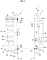
Fig. 2 is an exploded view of the scroll compressor shown inFig. 1 . -
Fig. 3 is a view as seen along an arrow in an A direction inFig. 2 . -
Fig. 4 is a view as seen along an arrow in a B direction inFig. 2 . -
Fig. 5 is a sectional view of an oil groove formed in a scroll compressor according to a first embodiment of the present disclosure. -
Fig. 6 is a view showing an oil groove according to a modification example of the first embodiment of the present disclosure. -
Fig. 7 is a sectional view taken along line VII-VII ofFig. 6 . -
Fig. 8 is a view showing an oil groove according to a modification example of the first embodiment of the present disclosure. -
Fig. 9 is a view when a lid section of a scroll compressor according to a second embodiment of the present disclosure is viewed from a body section side. -
Fig. 10 is a view showing an oil groove and a positioning pin of a scroll compressor according to a second embodiment of the present disclosure. - Hereinafter, an embodiment of a compressor according to the present disclosure will be described with reference to the drawings.
- Hereinafter, a first embodiment of the present disclosure will be described with reference to
Figs. 1 to 8 . - The compressor according to the present embodiment is a scroll compressor, and is applied to, for example, an air conditioner.
- As shown in
Figs. 1 and2 , a scroll compressor (compressor) 1 includes ahousing 11 that forms an outer shell. The refrigerant containing mist-like lubricating oil fills thehousing 11. Thehousing 11 includes acylindrical body section 11a and alid section 11b that closes an opening of thebody section 11a on one end side. Thebody section 11a and thelid section 11b are fixed to each other by a bolt or the like. Thelid section 11b has an outer peripheral portion that is in surface contact with anend plate 12a of afixed scroll 12 to be described later, and a central portion that is recessed from the outer peripheral portion in which adischarge cavity 23 to be described later or the like is formed. - In the
scroll compressor 1 of the present embodiment, a gasket or the like is not provided between thelid section 11b and thefixed scroll 12. That is, thefixed scroll 12 and a surface of the outer peripheral portion of thelid section 11b on thefixed scroll 12 side (hereinafter, referred to as a "contact surface 11ba") are in direct contact with each other. In addition, a gasket (not shown) is provided between thebody section 11a and thelid section 11b. That is, the gasket is interposed between thelid section 11b and thebody section 11a. - A
scroll compression mechanism 10 having thefixed scroll 12 and an orbitingscroll 13 is provided inside thehousing 11. Thescroll compression mechanism 10 compresses the refrigerant. - The
fixed scroll 12 is made of, for example, a metallic material. Thefixed scroll 12 has a disk-shaped end plate 12a and a scroll-shaped wall body 12b erected on a surface of theend plate 12a on one side. Thefixed scroll 12 is interposed and fixed between thebody section 11a and thelid section 11b of thehousing 11. The orbitingscroll 13 is made of, for example, a metallic material. Theorbiting scroll 13 has a disk-shaped end plate 13a and a scroll-shaped wall body 13b erected on a surface of theend plate 13a on one side, as in thefixed scroll 12. The orbitingscroll 13 is provided to be eccentric with a radius of revolution orbiting and to be out of phase by 180° with respect to thefixed scroll 12. In addition, thefixed scroll 12 and the orbitingscroll 13 are disposed such thatwall bodies wall bodies - The surface of the
end plate 12a of thefixed scroll 12 on the other side (hereinafter, referred to as "the other surface 12aa") is in surface contact with the outer peripheral portion of thelid section 11b. - In addition, the
scroll compressor 1 includes a main shaft (not shown) having a crank shaft at an end portion on the orbiting scroll 13 side. The main shaft is rotatably supported in thehousing 11 by a plurality of bearings. A motor is connected to one end of the main shaft in a longitudinal direction, and the main shaft is rotated by a driving force of the motor. - In addition, the
orbiting scroll 13 is fixed to the other end of the main shaft in the longitudinal direction. Specifically, a boss portion (not shown) is provided at the center of the other end surface of theend plate 13a of theorbiting scroll 13, and the eccentric portion of the crank shaft is rotatably accommodated in the boss portion via a bearing (not shown) and a drive bush (not shown). Accordingly, the orbitingscroll 13 is configured to perform a revolution orbiting motion by rotating the main shaft. In addition, a balance weight (not shown) is attached to the drive bush. - A
discharge port 21 that discharges a high-pressure refrigerant from the compression chamber is provided at the center of theend plate 12a of the fixedscroll 12. In addition, adischarge cavity 23 is formed between thelid section 11b of thehousing 11 and the other surface 12aa of theend plate 12a of the fixedscroll 12. Thedischarge cavity 23 is partitioned by a recessed portion provided in thelid section 11b and the other surface 12aa of theend plate 12a. - The
scroll compressor 1 causes theorbiting scroll 13 to perform a revolution orbiting motion by rotating a main shaft. Accordingly, the volume of the compression chamber is gradually reduced toward the central portion. Therefore, the refrigerant that has flowed into the compression chamber moves to the central portion, is compressed, and is discharged to thedischarge cavity 23 via thedischarge port 21. - As shown in
Figs. 1 to 3 , thescroll compressor 1 includes an oil separator (separating section) to which a refrigerant is guided from adischarge cavity 23. Theoil separator 29 is a long tubular body. Theoil separator 29 is accommodated inside thelid section 11b. The refrigerant guided to the inside of theoil separator 29 has an orbiting flow, and the lubricating oil is separated by centrifugal separation. In this way, theoil separator 29 separates the lubricating oil from the refrigerant guided from thedischarge cavity 23. The lubricating oil separated by theoil separator 29 is guided to the oil storage chamber (storage section) 24 through the lubricatingoil flow path 25 connected to the lower end portion of theoil separator 29. Afilter 26 is provided at an intermediate position of the lubricatingoil flow path 25. Thefilter 26 collects impurities such as dust contained in the lubricating oil. - The oil storage chamber (storage section) 24 that temporarily stores the lubricating oil separated by the
oil separator 29 is provided below thedischarge cavity 23. Theoil storage chamber 24 is partitioned by a recessed portion provided in thelid section 11b and the other surface 12aa of theend plate 12a. - The lubricating oil stored in the
oil storage chamber 24 is guided to a lubricating oil groove (oil groove) 30 (refer toFig. 4 ) (to be described later) formed on the other surface 12aa of theend plate 12a via a high-pressure side oil return flow path (inlet flow path) 27 provided in thelid section 11b. The high-pressure side oilreturn flow path 27 has aninclined section 27a extending obliquely downward and ahorizontal section 27b bent from theinclined section 27a and extending substantially horizontally. The high-pressure side oilreturn flow path 27 is bent such that the angle formed by theinclined section 27a and thehorizontal section 27b is an acute angle. - The lubricating oil that has circulated through the lubricating
oil groove 30 is guided to a low-pressure side oil return flow path (outlet flow path) 32 formed inside thewall body 12b of the fixedscroll 12 on the outermost peripheral side. The lubricating oil that has circulated through the low-pressure side oilreturn flow path 32 is returned to the space on theorbiting scroll 13 side and is used for lubricating a driving mechanism such as various bearings and a drive bush. An O-ring groove 34 is formed on the other surface 12aa of theend plate 12a of the fixedscroll 12. An O-ring 35 is accommodated in the O-ring groove 34. The O-ring 35 seals the refrigerant in the high-pressure region such that the high-pressure refrigerant in thedischarge cavity 23 does not move to the low-pressure side oilreturn flow path 32 side. - Next, details of the lubricating
oil groove 30 formed on the other surface 12aa of theend plate 12a of the fixedscroll 12 will be described with reference toFigs. 4 and 5 . - As shown in
Fig. 4 , the lubricatingoil groove 30 is formed on the other surface 12aa of theend plate 12a of the fixedscroll 12. Specifically, the lubricatingoil groove 30 is formed in the outer peripheral portion of the other surface 12aa. The lubricatingoil groove 30 extends over the entire circumference along the outer peripheral edge of theend plate 12a. That is, the lubricatingoil groove 30 has an annular shape when the other surface 12aa of theend plate 12a is viewed in a plan view. In addition, the lubricatingoil groove 30 is provided outside the O-ring groove 34 in the radial direction. The width (length in the radial direction) of the lubricatingoil groove 30 is shorter than the width of the O-ring groove 34. - In addition, the other surface 12aa is in surface contact with the contact surface 11ba of the
lid section 11b. For this reason, the upper portion of the lubricatingoil groove 30 is closed by thelid section 11b. That is, the lubricatingoil groove 30 and thelid section 11b partition a flow path through which the lubricating oil circulates. - The
downstream end 27c of the high-pressure side oilreturn flow path 27 is connected to the lower end of the lubricatingoil groove 30. In addition, theupstream end 32a of the low-pressure side oilreturn flow path 32 is connected to the upper end of the lubricatingoil groove 30. In a case where the radial positions of the lubricatingoil groove 30 and thedownstream end 27c of the high-pressure side oilreturn flow path 27 and/or theupstream end 32a of the low-pressure side oilreturn flow path 32 do not coincide with each other, a connection portion that connects the lubricatingoil groove 30 and thedownstream end 27c of the high-pressure side oilreturn flow path 27 and/or theupstream end 32a of the low-pressure side oilreturn flow path 32 may be formed. The connection portion may be, for example, a counterbore portion (recessed portion having a circular shape in a plan view) formed on the other surface 12aa of theend plate 12a. By making the connection portion as the counterbore portion in this way, the connection portion (counterbore portion) can also be formed by using a device for forming the reference hole when the reference hole or the like is processed on the other surface 12aa of theend plate 12a. Therefore, the connection portion can be easily formed. - In the present embodiment, since the
downstream end 27c of the high-pressure side oilreturn flow path 27 and theupstream end 32a of the low-pressure side oilreturn flow path 32 are positioned outside the lubricatingoil groove 30 in the radial direction, the upstreamside counterbore portion 30a connecting the lubricatingoil groove 30 and thedownstream end 27c of the high-pressure side oilreturn flow path 27 and the downstreamside counterbore portion 30b connecting the lubricatingoil groove 30 and theupstream end 32a of the low-pressure side oilreturn flow path 32 are provided. As described above, by providing the counterbore portion (connection portion), it is not necessary to make the radial positions of the lubricatingoil groove 30 and thedownstream end 27c of the high-pressure side oilreturn flow path 27 and/or theupstream end 32a of the low-pressure side oilreturn flow path 32 coincide with each other. Accordingly, the degree of freedom in the layout of thedownstream end 27c of the high-pressure side oilreturn flow path 27 and/or theupstream end 32a of the low-pressure side oilreturn flow path 32 can be improved. - As shown in
Fig. 5 , the lubricatingoil groove 30 has a substantially triangular cross section in a longitudinal direction (flow path cross section). Specifically, a triangular vertex portion, which is the bottom surface of the lubricatingoil groove 30, is curved. The curved vertex portion has a curvature radius R of 0.4 mm or more. - The lubricating
oil groove 30 is formed by turning processing. In addition, the lubricatingoil groove 30 is formed at the same time when the O-ring groove 34 or the like is formed on the other surface 12aa of theend plate 12a by turning processing. - Next, a part of the flow of the refrigerant and the lubricating oil in the
scroll compressor 1 according to the present embodiment will be described. - In the
scroll compressor 1, a high-pressure refrigerant is discharged from adischarge port 21 to adischarge cavity 23 during operation. The refrigerant discharged into thedischarge cavity 23 is mixed with mist-like lubricating oil. The refrigerant discharged into thedischarge cavity 23 is guided to theoil separator 29 via therefrigerant flow path 22. Since therefrigerant flow path 22 is installed so that the refrigerant has an orbiting flow, the refrigerant introduced into theoil separator 29 orbits inside theoil separator 29. In this manner, the lubricating oil is centrifugally separated from the refrigerant in theoil separator 29. The separated lubricating oil is guided to theoil storage chamber 24 via the lubricatingoil flow path 25. At this time, the impurities are removed by thefilter 26. The lubricating oil in theoil storage chamber 24 flows into the lubricatingoil groove 30 via the high-pressure side oilreturn flow path 27 because of a differential pressure between the discharge cavity 23 (specifically, oil storage chamber 24) and the low-pressure side oilreturn flow path 32 side. The lubricating oil that has flowed into the lubricatingoil groove 30 circulates inside the lubricating oil groove 30 (refer to arrows inFig. 4 ). At this time, the lubricating oil is decompressed. The lubricating oil discharged from the lubricatingoil groove 30 flows into the low-pressure side oilreturn flow path 32. The lubricating oil that has circulated inside the low-pressure side oilreturn flow path 32 is discharged from the downstream end. The lubricating oil discharged from the low-pressure side oilreturn flow path 32 falls downward because of gravity, and lubricates a bearing, a drive bush, or the like provided below. - In
Fig. 4 , for the sake of illustration, only one direction (counterclockwise direction inFig. 4 ) of the circulation direction of the lubricating oil in the lubricatingoil groove 30 is shown by an arrow, and the arrow in the other direction (clockwise direction inFig. 4 ) is omitted. However, the lubricating oil circulates in both the one direction and the other direction in the lubricatingoil groove 30. - According to the present embodiment, the following operation and effects are obtained.
- In the present embodiment, the lubricating
oil groove 30 guiding the lubricating oil from theoil storage chamber 24 is formed on the other surface 12aa of theend plate 12a. The other surface 12aa of theend plate 12a is a flat surface, and has a relatively large area. For this reason, the lubricatingoil groove 30 can be easily processed. Therefore, the processing step of the lubricatingoil groove 30 can be simplified. - In addition, since the fixed
scroll 12 is made of a material having relatively high rigidity, the fixedscroll 12 is difficult to deform even in a case where the lubricatingoil groove 30 is formed. For this reason, it is not necessary to check the deformation of the fixedscroll 12 even when the lubricatingoil groove 30 is formed. Accordingly, a step of checking a member in which the lubricatingoil groove 30 is formed at the time of the assembly of thescroll compressor 1 can be omitted. Therefore, the assembly step of thescroll compressor 1 can be simplified. - As described above, the processing step and the assembly step can be simplified, and thus, the cost at the time of processing or assembly can be reduced.
- In the present embodiment, the lubricating
oil groove 30 is formed in an annular shape. Accordingly, the lubricatingoil groove 30 can be formed by turning processing. Therefore, the lubricatingoil groove 30 can be easily formed. In addition, in a case where a groove (for example, O-ring groove 34) or the like other than the lubricatingoil groove 30 is formed on the other surface 12aa of theend plate 12a by turning processing, the lubricatingoil groove 30 can also be formed when performing turning processing to form the other groove. Therefore, the lubricatingoil groove 30 can be easily formed as compared with a case where the other groove and the lubricatingoil groove 30 are processed in separate steps. - In the present embodiment, the O-
ring groove 34 in which the O-ring 35 is provided is formed inside the lubricatingoil groove 30 in a radial direction. Accordingly, the leakage of the refrigerant can be suppressed. - In the present embodiment, the cross section of the lubricating
oil groove 30 has a substantially triangular shape. Accordingly, for example, in a case where the lubricatingoil groove 30 is formed by turning processing, the lubricatingoil groove 30 can be easily formed. Therefore, a cost at the time of processing can be reduced. - Next, a modification example of the present embodiment will be described with reference to
Figs. 6 and 7 . In the present modification example, the positioning pin is provided inside the lubricatingoil groove 30, which is different from the first embodiment. Other points are similar to the first embodiment, and thus, similar configurations will be denoted by the same reference numerals with detailed description thereof omitted. - As shown in
Figs. 6 and 7 , a positioning pin (flow path cross section reducing portion) 40 is provided inside the lubricatingoil groove 30 according to the present modification example. Thepositioning pin 40 is a pin for positioning the fixedscroll 12 and thehousing 11. As shown inFig. 6 , two positioningpins 40 are provided, and the twopositioning pins 40 are disposed at an interval of 180 degrees in the circumferential direction. - As shown in
Fig. 7 , an end portion of thepositioning pin 40 on thelid section 11b side is inserted into a pin hole formed on the contact surface 11ba of thelid section 11b. In addition, an end portion of thepositioning pin 40 on theend plate 12a side is inserted into a pin hole formed on the bottom surface of the lubricatingoil groove 30. As shown inFig. 7 , the area of the flow path cross section of the lubricatingoil groove 30 is reduced in a portion where thepositioning pin 40 is provided. - According to the present modification example, the following operation and effects are obtained.
- In the present modification example, a
positioning pin 40 that reduces the flow path cross section is provided in the lubricatingoil groove 30. Accordingly, the area of the flow path cross section of the lubricatingoil groove 30 can be adjusted by adjusting the size and the like of thepositioning pin 40. Therefore, the amount of decompression of the lubricating oil circulating through the lubricatingoil groove 30 can be adjusted. - In addition, the
positioning pin 40 for positioning the fixedscroll 12 and thehousing 11 is used to reduce the area of the flow path cross section. Accordingly, it is not necessary to provide a new component separately in order to reduce the area of the flow path cross section, and thus, the number of components can be reduced. Therefore, the assembly step can be simplified, and the cost can be reduced. - Next, a modification example of the present embodiment will be described with reference to
Fig. 8 . In the present modification example, the lubricating oil groove includes a plurality of annular grooves and connection portions, which is different from the first embodiment. Other points are similar to the first embodiment, and thus, similar configurations will be denoted by the same reference numerals with detailed description thereof omitted. - As shown in
Fig. 8 , the lubricatingoil groove 60 according to the present modification example includes a firstannular groove 61 that is connected to thedownstream end 27c of the high-pressure side oilreturn flow path 27 that guides the lubricating oil to the lubricatingoil groove 60, a secondannular groove 62 that is provided concentrically with the firstannular groove 61 and that is connected to theupstream end 32a of the low-pressure side oilreturn flow path 32 from which the lubricating oil is discharged from the lubricatingoil groove 60, and a counterbore portion (connection portion) 63 that connects the firstannular groove 61 and the secondannular groove 62. The secondannular groove 62 is provided outside the firstannular groove 61 in the radial direction. - In the present modification example, as indicated by arrows in
Fig. 8 , the lubricating oil that has flowed into the firstannular groove 61 from thedownstream end 27c of the high-pressure side oilreturn flow path 27 flows into the secondannular groove 62 via thecounterbore portion 63. The lubricating oil that has flowed into the secondannular groove 62 flows into the low-pressure side oilreturn flow path 32 from theupstream end 32a of the low-pressure side oilreturn flow path 32. - In
Fig. 8 , for the sake of illustration, only one direction (counterclockwise direction inFig. 8 ) of the circulation direction of the lubricating oil in the lubricatingoil groove 60 is shown by an arrow, and the arrow in the other direction (clockwise direction inFig. 8 ) is omitted. However, the lubricating oil circulates in both the one direction and the other direction in the lubricatingoil groove 60. - According to the present modification example, the following operation and effects are obtained.
- In the present modification example, even in a case where the radial positions of the
downstream end 27c of the high-pressure side oilreturn flow path 27 and theupstream end 32a of the low-pressure side oilreturn flow path 32 are different from each other, the lubricating oil can be guided from the high-pressure side oilreturn flow path 27 to the low-pressure side oilreturn flow path 32 via the lubricatingoil groove 60. Accordingly, it is not necessary to make the radial positions of thedownstream end 27c of the high-pressure side oilreturn flow path 27 and theupstream end 32a of the low-pressure side oilreturn flow path 32 coincide with each other. Accordingly, the degree of freedom in the layout of thedownstream end 27c of the high-pressure side oilreturn flow path 27 and theupstream end 32a of the low-pressure side oilreturn flow path 32 can be improved. - In addition, since both the first
annular groove 61 and the secondannular groove 62 have an annular shape, the firstannular groove 61 and the secondannular groove 62 can be formed by turning processing. Therefore, processing can be facilitated. - In addition, by making the connection portion connecting the first
annular groove 61 and the secondannular groove 62 as the counterbore portion as in the present modification example, the connection portion (counterbore portion 63) can also be formed by using a device for forming the reference hole when the reference hole or the like is processed on the other surface 12aa of theend plate 12a. Therefore, the connection portion (counterbore portion 63) can be easily formed. - In the present modification example, the example in which two annular grooves are provided has been described. However, three or more annular grooves may be provided. In this case, a counterbore portion connecting all the annular grooves may be provided, or a plurality of counterbore portions connecting only the annular grooves adjacent to each other in the radial direction (for example, in a case where there are three annular grooves, two counterbore portions: a counterbore portion connecting the outermost peripheral annular groove and the central annular groove and a counterbore portion connecting the innermost peripheral annular groove and the central annular groove) may be provided.
- Next, a second embodiment of the present disclosure will be described with reference to
Figs. 9 to 10 . - In the
scroll compressor 1 of the present embodiment, thegasket 9 is provided between theend plate 12a of the fixedscroll 12 and thelid section 11b of thehousing 11, which is different from the first embodiment. Other points are similar to the first embodiment, and thus, similar configurations will be denoted by the same reference numerals with detailed description thereof omitted. - In the
scroll compressor 1 according to the present embodiment, thegasket 9 is provided between thebody section 11a and thelid section 11b and between thelid section 11b and the fixedscroll 12. That is, thegasket 9 is interposed between thelid section 11b, thebody section 11a, and the fixedscroll 12. - As shown in
Fig. 9 , thegasket 9 is formed in a substantially annular shape in a plan view. In addition, thegasket 9 has a plurality ofprotrusion portions 9a that protrude to the outside in the radial direction from the outer peripheral edge. Thegasket 9 is in surface contact with the contact surface 11ba of thelid section 11b. - In addition, the other surface 12aa of the
end plate 12a of the fixedscroll 12 is in surface contact with thegasket 9. In addition, thegasket 9 is interposed between the other surface 12aa and the outer peripheral portion of thelid section 11b. - As described above, the other surface 12aa of the
end plate 12a is in surface contact with thegasket 9. For this reason, the upper portion of the lubricatingoil groove 30 is closed by thegasket 9. That is, the lubricatingoil groove 30 and thegasket 9 partition a flow path through which the lubricating oil circulates. - Next, a modification example of the present embodiment will be described with reference to
Fig. 10 . In the present modification example, the positioning pin is provided inside the lubricatingoil groove 30, which is different from the second embodiment. Other points are similar to the second embodiment, and thus, similar configurations will be denoted by the same reference numerals with detailed description thereof omitted. - As in the modification example 1 of the first embodiment, in the
scroll compressor 1 according to the present embodiment, thepositioning pin 40 may be provided inside the lubricatingoil groove 30. In the present embodiment, thepositioning pin 40 penetrates thegasket 9. In addition, a tip of thepositioning pin 40 is inserted into a pin hole formed on the bottom surface of the lubricatingoil groove 30. As shown inFig. 10 , the area of the flow path cross section of the lubricatingoil groove 30 is reduced in a portion where thepositioning pin 40 is provided. - Also in the present modification example, the same effects as those of the modification example 1 of the first embodiment are exhibited.
- The present disclosure is not limited to each of the embodiments described above, and can be appropriately modified within a scope which does not depart from the gist of the present disclosure.
- The compressor described in the embodiment described above is understood as follows, for example.
- A compressor according to an aspect of the present disclosure includes a housing (11) that forms an outer shell, a scroll compression mechanism (10) that has an orbiting scroll (13) performing an orbiting motion and a fixed scroll (12), which has an end plate (12a) and a wall body (12b) erected on one surface of the end plate and is fixed to the housing, that is provided inside the housing, and that compresses a refrigerant containing lubricating oil, a contact section (9, 11b) that is in surface contact with the other surface (12aa) of the end plate, a separating section (29) that separates the lubricating oil from the refrigerant compressed by the scroll compression mechanism, and a storage section (24) that stores the lubricating oil separated by the separating section, in which an oil groove (30) through which the lubricating oil discharged from the storage section circulates is formed on the other surface of the end plate.
- In the above configuration, the oil groove for guiding the lubricating oil from the storage section is formed on the other surface of the end plate. The other surface of the end plate is a flat surface, and has a relatively large area. For this reason, the oil groove can be easily processed. Therefore, the processing step of the oil groove can be simplified.
- In addition, since the fixed scroll is made of a material having relatively high rigidity, the fixed scroll is difficult to deform even in a case where the oil groove is formed. For this reason, it is not necessary to check the deformation of the fixed scroll even when the oil groove is formed. Accordingly, a step of checking a member in which the oil groove is formed at the time of the assembly of the compressor can be omitted. Therefore, the assembly step of the compressor can be simplified.
- As described above, the processing step and the assembly step can be simplified, and thus, the cost at the time of processing or assembly can be reduced.
- In addition, in the compressor according to the aspect of the present disclosure, the oil groove extends along an outer peripheral edge of the end plate, and has an annular shape when the other surface of the end plate is viewed in a plan view.
- In the above configuration, the oil groove is formed in an annular shape. Accordingly, the oil groove can be formed by turning processing. Therefore, the oil groove can be easily formed. In addition, in a case where a groove (for example, O-ring groove) or the like other than the oil groove is formed on the other surface of the end plate by turning processing, the oil groove can also be formed when performing turning processing to form the other groove. Therefore, the oil groove can be easily formed as compared with a case where the other groove and the oil groove are processed in separate steps.
- In addition, in the compressor according to the aspect of the present disclosure, an O-ring groove (34) in which an O-ring (35) is provided is formed inside the oil groove in a radial direction.
- In the above configuration, the O-ring groove in which the O-ring is provided is formed inside the oil groove in a radial direction. Accordingly, the leakage of the refrigerant can be suppressed.
- In addition, in the compressor according to the aspect of the present disclosure, the oil groove includes a first annular groove (61) that is connected to an inlet flow path (27) that guides the lubricating oil to the oil groove, a second annular groove (62) that is provided concentrically with the first annular groove and that is connected to an outlet flow path (32) from which the lubricating oil is discharged from the oil groove, and a connection portion (63) that connects the first annular groove and the second annular groove.
- In the above configuration, even when the radial positions of the downstream end of the inlet flow path and the upstream end of the outlet flow path are different from each other, the lubricating oil can be guided from the inlet flow path to the outlet flow path via the oil groove. Accordingly, it is not necessary to make the radial positions of the downstream end of the inlet flow path and the upstream end of the outlet flow path coincide with each other. Therefore, the degree of freedom in the layout of the downstream end of the inlet flow path and the upstream end of the outlet flow path can be improved.
- In addition, since both the first annular groove and the second annular groove have an annular shape, the first annular groove and the second annular groove can be formed by turning processing. Therefore, processing can be facilitated.
- In addition, in the compressor according to the aspect of the present disclosure, a flow path cross section reducing portion (40) that reduces a flow path cross section is provided inside the oil groove.
- In the above configuration, the flow path cross section reducing portion that reduces the flow path cross section is provided inside the oil groove. Accordingly, the area of the flow path cross section of the oil groove can be adjusted by adjusting the size and the like of the flow path cross section reducing portion. Therefore, the amount of decompression of the lubricating oil circulating through the oil groove can be adjusted.
- Examples of the flow path cross section reducing portion include a positioning pin and a gasket.
- In addition, in the compressor according to the aspect of the present disclosure, the oil groove has a triangular cross section when cut in a plane intersecting an extending direction.
- In the above configuration, the cross section of the oil groove has a triangular shape. Accordingly, for example, in a case where the oil groove is formed by turning processing, the oil groove can be easily formed. Therefore, a cost at the time of processing can be reduced.
-
- 1: scroll compressor
- 9: gasket
- 9a: protrusion portion
- 10: scroll compression mechanism
- 11: housing
- 11a: body section
- 11b: lid section
- 11ba: contact surface
- 12: fixed scroll
- 12a: end plate
- 12aa: the other surface
- 12b: wall body
- 13: orbiting scroll
- 13a: end plate
- 13b: wall body
- 21: discharge port
- 22: refrigerant flow path
- 23: discharge cavity
- 24: oil storage chamber (storage section)
- 25: lubricating oil flow path
- 26: filter
- 27: high-pressure side oil return flow path (inlet flow path)
- 27a: inclined section
- 27b: horizontal section
- 27c: downstream end
- 29: oil separator
- 30: lubricating oil groove (oil groove)
- 30a: upstream side counterbore portion
- 30b: downstream side counterbore portion
- 32: low-pressure side oil return flow path (outlet flow path)
- 32a: upstream end
- 34: O-ring groove
- 35: O-ring
- 40: positioning pin (flow path cross section reducing portion)
- 60: lubricating oil groove
- 61: first annular groove
- 62: second annular groove
- 63: counterbore portion (connection portion)
Claims (6)
- A compressor comprising:a housing that forms an outer shell;a scroll compression mechanism that has an orbiting scroll performing an orbiting motion and a fixed scroll, which has an end plate and a wall body erected on one surface of the end plate and is fixed to the housing, that is provided inside the housing, and that compresses a refrigerant containing lubricating oil;a contact section that is in surface contact with the other surface of the end plate;a separating section that separates the lubricating oil from the refrigerant compressed by the scroll compression mechanism; anda storage section that stores the lubricating oil separated by the separating section,wherein an oil groove through which the lubricating oil discharged from the storage section circulates is formed on the other surface of the end plate.
- The compressor according to Claim 1, wherein the oil groove extends along an outer peripheral edge of the end plate, and has an annular shape when the other surface of the end plate is viewed in a plan view.
- The compressor according to Claim 2, wherein an O-ring groove in which an O-ring is provided is formed inside the oil groove in a radial direction.
- The compressor according to any one of Claims 1 to 3, wherein the oil groove includes a first annular groove that is connected to an inlet flow path that guides the lubricating oil to the oil groove, a second annular groove that is provided concentrically with the first annular groove and that is connected to an outlet flow path from which the lubricating oil is discharged from the oil groove, and a connection portion that connects the first annular groove and the second annular groove.
- The compressor according to any one of Claims 1 to 4, wherein a flow path cross section reducing portion that reduces a flow path cross section is provided inside the oil groove.
- The compressor according to any one of Claims 1 to 5, wherein the oil groove has a triangular cross section when cut in a plane intersecting an extending direction.
Applications Claiming Priority (2)
| Application Number | Priority Date | Filing Date | Title |
|---|---|---|---|
| JP2022001636A JP7797210B2 (en) | 2022-01-07 | 2022-01-07 | Compressor |
| PCT/JP2022/048230 WO2023132305A1 (en) | 2022-01-07 | 2022-12-27 | Compressor |
Publications (3)
| Publication Number | Publication Date |
|---|---|
| EP4443002A1 true EP4443002A1 (en) | 2024-10-09 |
| EP4443002A4 EP4443002A4 (en) | 2025-01-22 |
| EP4443002B1 EP4443002B1 (en) | 2026-04-22 |
Family
ID=87073718
Family Applications (1)
| Application Number | Title | Priority Date | Filing Date |
|---|---|---|---|
| EP22918888.3A Active EP4443002B1 (en) | 2022-01-07 | 2022-12-27 | Compressor |
Country Status (4)
| Country | Link |
|---|---|
| EP (1) | EP4443002B1 (en) |
| JP (1) | JP7797210B2 (en) |
| CN (1) | CN118475772A (en) |
| WO (1) | WO2023132305A1 (en) |
Families Citing this family (2)
| Publication number | Priority date | Publication date | Assignee | Title |
|---|---|---|---|---|
| JP2025116429A (en) * | 2024-01-29 | 2025-08-08 | 三菱重工サーマルシステムズ株式会社 | Scroll compressor and method for assembling scroll compressor |
| JP2025144837A (en) * | 2024-03-21 | 2025-10-03 | サンデン株式会社 | Scroll Compressor |
Family Cites Families (6)
| Publication number | Priority date | Publication date | Assignee | Title |
|---|---|---|---|---|
| JP2003232285A (en) * | 2002-02-12 | 2003-08-22 | Sanden Corp | Scroll type compressor |
| JP4256801B2 (en) * | 2004-02-26 | 2009-04-22 | 三菱重工業株式会社 | Compressor and air conditioner |
| JP4192158B2 (en) * | 2005-03-24 | 2008-12-03 | 日立アプライアンス株式会社 | Hermetic scroll compressor and refrigeration air conditioner |
| JP2007186999A (en) * | 2006-01-10 | 2007-07-26 | Sanden Corp | Scroll compressor |
| CN109209868A (en) * | 2018-10-11 | 2019-01-15 | 南京奥特佳新能源科技有限公司 | A kind of self-lubricating screw compressor and its quiet disk |
| CN111120308B (en) * | 2020-01-03 | 2021-07-09 | 南京奥特佳新能源科技有限公司 | Scroll compressor with oil return system |
-
2022
- 2022-01-07 JP JP2022001636A patent/JP7797210B2/en active Active
- 2022-12-27 CN CN202280086782.8A patent/CN118475772A/en active Pending
- 2022-12-27 EP EP22918888.3A patent/EP4443002B1/en active Active
- 2022-12-27 WO PCT/JP2022/048230 patent/WO2023132305A1/en not_active Ceased
Also Published As
| Publication number | Publication date |
|---|---|
| JP2023101182A (en) | 2023-07-20 |
| CN118475772A (en) | 2024-08-09 |
| JP7797210B2 (en) | 2026-01-13 |
| EP4443002B1 (en) | 2026-04-22 |
| WO2023132305A1 (en) | 2023-07-13 |
| EP4443002A4 (en) | 2025-01-22 |
Similar Documents
| Publication | Publication Date | Title |
|---|---|---|
| EP2218914A2 (en) | Scroll-type fluid machine | |
| US7140852B2 (en) | Scroll compressor having an oil reservoir surrounding the discharge chamber and an oil separator in the rear housing | |
| US9004887B2 (en) | Thrust plate for a horizontal scroll compressor and a horizontal scroll compressor having the same | |
| EP2309132B1 (en) | Horizontal scroll compressor | |
| EP4443002B1 (en) | Compressor | |
| EP3508724B1 (en) | Scroll compressor | |
| KR102318707B1 (en) | Motor-driven compressor | |
| US8945265B2 (en) | Compressor | |
| EP1471258A1 (en) | Electric compressor | |
| US9651047B2 (en) | Compressor having a partitioned discharge chamber | |
| JP7226194B2 (en) | electric compressor | |
| EP2653650A2 (en) | Scroll type compressor | |
| JP2019056322A (en) | Compressor | |
| EP1719913A2 (en) | Horizontal scroll compressor | |
| EP1464840A1 (en) | Scroll compressor | |
| US8535029B2 (en) | Scroll type compressor having reinforced fixed scroll | |
| EP3190297A1 (en) | Compressor | |
| EP2236828B1 (en) | Scroll compressor | |
| CN217029311U (en) | Main bearing seat for scroll compressor and scroll compressor | |
| EP3985256A1 (en) | Scroll compressor | |
| JP2000130370A (en) | High pressure dome type compressor | |
| US20040126252A1 (en) | Compressor and mechanism for separating lubricating liquid | |
| CN116838605B (en) | Main bearing housing for scroll compressors and scroll compressors | |
| EP3992461B1 (en) | Scroll compressor | |
| JP7838506B2 (en) | compressor |
Legal Events
| Date | Code | Title | Description |
|---|---|---|---|
| STAA | Information on the status of an ep patent application or granted ep patent |
Free format text: STATUS: THE INTERNATIONAL PUBLICATION HAS BEEN MADE |
|
| PUAI | Public reference made under article 153(3) epc to a published international application that has entered the european phase |
Free format text: ORIGINAL CODE: 0009012 |
|
| STAA | Information on the status of an ep patent application or granted ep patent |
Free format text: STATUS: REQUEST FOR EXAMINATION WAS MADE |
|
| 17P | Request for examination filed |
Effective date: 20240702 |
|
| AK | Designated contracting states |
Kind code of ref document: A1 Designated state(s): AL AT BE BG CH CY CZ DE DK EE ES FI FR GB GR HR HU IE IS IT LI LT LU LV MC ME MK MT NL NO PL PT RO RS SE SI SK SM TR |
|
| A4 | Supplementary search report drawn up and despatched |
Effective date: 20241223 |
|
| RIC1 | Information provided on ipc code assigned before grant |
Ipc: F04C 29/02 20060101ALI20241217BHEP Ipc: F04C 18/02 20060101AFI20241217BHEP |
|
| DAV | Request for validation of the european patent (deleted) | ||
| DAX | Request for extension of the european patent (deleted) | ||
| GRAP | Despatch of communication of intention to grant a patent |
Free format text: ORIGINAL CODE: EPIDOSNIGR1 |
|
| STAA | Information on the status of an ep patent application or granted ep patent |
Free format text: STATUS: GRANT OF PATENT IS INTENDED |
|
| RIC1 | Information provided on ipc code assigned before grant |
Ipc: F04C 18/02 20060101AFI20251031BHEP Ipc: F04C 29/02 20060101ALI20251031BHEP Ipc: F04B 39/02 20060101ALI20251031BHEP |
|
| INTG | Intention to grant announced |
Effective date: 20251113 |
|
| GRAS | Grant fee paid |
Free format text: ORIGINAL CODE: EPIDOSNIGR3 |
|
| GRAA | (expected) grant |
Free format text: ORIGINAL CODE: 0009210 |
|
| STAA | Information on the status of an ep patent application or granted ep patent |
Free format text: STATUS: THE PATENT HAS BEEN GRANTED |
|
| AK | Designated contracting states |
Kind code of ref document: B1 Designated state(s): AL AT BE BG CH CY CZ DE DK EE ES FI FR GB GR HR HU IE IS IT LI LT LU LV MC ME MK MT NL NO PL PT RO RS SE SI SK SM TR |
|
| P01 | Opt-out of the competence of the unified patent court (upc) registered |
Free format text: CASE NUMBER: UPC_APP_0009896_4443002/2026 Effective date: 20260313 |
|
| REG | Reference to a national code |
Ref country code: CH Ref legal event code: F10 Free format text: ST27 STATUS EVENT CODE: U-0-0-F10-F00 (AS PROVIDED BY THE NATIONAL OFFICE) Effective date: 20260422 Ref country code: GB Ref legal event code: FG4D |
|
| REG | Reference to a national code |
Ref country code: DE Ref legal event code: R096 Ref document number: 602022035302 Country of ref document: DE |