EP4442968A1 - Assembly for mounting an auxiliary component to an engine case of a gas turbine engine, gas turbine engine and locator for mounting an auxiliary component to an engine case of a gas turbine engine - Google Patents
Assembly for mounting an auxiliary component to an engine case of a gas turbine engine, gas turbine engine and locator for mounting an auxiliary component to an engine case of a gas turbine engine Download PDFInfo
- Publication number
- EP4442968A1 EP4442968A1 EP24166544.7A EP24166544A EP4442968A1 EP 4442968 A1 EP4442968 A1 EP 4442968A1 EP 24166544 A EP24166544 A EP 24166544A EP 4442968 A1 EP4442968 A1 EP 4442968A1
- Authority
- EP
- European Patent Office
- Prior art keywords
- gas turbine
- aperture
- engine
- turbine engine
- partially
- Prior art date
- Legal status (The legal status is an assumption and is not a legal conclusion. Google has not performed a legal analysis and makes no representation as to the accuracy of the status listed.)
- Pending
Links
Images

Classifications
-
- F—MECHANICAL ENGINEERING; LIGHTING; HEATING; WEAPONS; BLASTING
- F01—MACHINES OR ENGINES IN GENERAL; ENGINE PLANTS IN GENERAL; STEAM ENGINES
- F01D—NON-POSITIVE DISPLACEMENT MACHINES OR ENGINES, e.g. STEAM TURBINES
- F01D21/00—Shutting-down of machines or engines, e.g. in emergency; Regulating, controlling, or safety means not otherwise provided for
- F01D21/04—Shutting-down of machines or engines, e.g. in emergency; Regulating, controlling, or safety means not otherwise provided for responsive to undesired position of rotor relative to stator or to breaking-off of a part of the rotor, e.g. indicating such position
- F01D21/045—Shutting-down of machines or engines, e.g. in emergency; Regulating, controlling, or safety means not otherwise provided for responsive to undesired position of rotor relative to stator or to breaking-off of a part of the rotor, e.g. indicating such position special arrangements in stators or in rotors dealing with breaking-off of part of rotor
-
- F—MECHANICAL ENGINEERING; LIGHTING; HEATING; WEAPONS; BLASTING
- F02—COMBUSTION ENGINES; HOT-GAS OR COMBUSTION-PRODUCT ENGINE PLANTS
- F02C—GAS-TURBINE PLANTS; AIR INTAKES FOR JET-PROPULSION PLANTS; CONTROLLING FUEL SUPPLY IN AIR-BREATHING JET-PROPULSION PLANTS
- F02C7/00—Features, components parts, details or accessories, not provided for in, or of interest apart form groups F02C1/00 - F02C6/00; Air intakes for jet-propulsion plants
- F02C7/32—Arrangement, mounting, or driving, of auxiliaries
-
- F—MECHANICAL ENGINEERING; LIGHTING; HEATING; WEAPONS; BLASTING
- F01—MACHINES OR ENGINES IN GENERAL; ENGINE PLANTS IN GENERAL; STEAM ENGINES
- F01D—NON-POSITIVE DISPLACEMENT MACHINES OR ENGINES, e.g. STEAM TURBINES
- F01D25/00—Component parts, details, or accessories, not provided for in, or of interest apart from, other groups
- F01D25/28—Supporting or mounting arrangements, e.g. for turbine casing
-
- F—MECHANICAL ENGINEERING; LIGHTING; HEATING; WEAPONS; BLASTING
- F02—COMBUSTION ENGINES; HOT-GAS OR COMBUSTION-PRODUCT ENGINE PLANTS
- F02C—GAS-TURBINE PLANTS; AIR INTAKES FOR JET-PROPULSION PLANTS; CONTROLLING FUEL SUPPLY IN AIR-BREATHING JET-PROPULSION PLANTS
- F02C7/00—Features, components parts, details or accessories, not provided for in, or of interest apart form groups F02C1/00 - F02C6/00; Air intakes for jet-propulsion plants
- F02C7/20—Mounting or supporting of plant; Accommodating heat expansion or creep
-
- F—MECHANICAL ENGINEERING; LIGHTING; HEATING; WEAPONS; BLASTING
- F05—INDEXING SCHEMES RELATING TO ENGINES OR PUMPS IN VARIOUS SUBCLASSES OF CLASSES F01-F04
- F05D—INDEXING SCHEME FOR ASPECTS RELATING TO NON-POSITIVE-DISPLACEMENT MACHINES OR ENGINES, GAS-TURBINES OR JET-PROPULSION PLANTS
- F05D2250/00—Geometry
- F05D2250/20—Three-dimensional
- F05D2250/24—Three-dimensional ellipsoidal
- F05D2250/241—Three-dimensional ellipsoidal spherical
-
- F—MECHANICAL ENGINEERING; LIGHTING; HEATING; WEAPONS; BLASTING
- F05—INDEXING SCHEMES RELATING TO ENGINES OR PUMPS IN VARIOUS SUBCLASSES OF CLASSES F01-F04
- F05D—INDEXING SCHEME FOR ASPECTS RELATING TO NON-POSITIVE-DISPLACEMENT MACHINES OR ENGINES, GAS-TURBINES OR JET-PROPULSION PLANTS
- F05D2250/00—Geometry
- F05D2250/20—Three-dimensional
- F05D2250/28—Three-dimensional patterned
- F05D2250/283—Three-dimensional patterned honeycomb
-
- F—MECHANICAL ENGINEERING; LIGHTING; HEATING; WEAPONS; BLASTING
- F05—INDEXING SCHEMES RELATING TO ENGINES OR PUMPS IN VARIOUS SUBCLASSES OF CLASSES F01-F04
- F05D—INDEXING SCHEME FOR ASPECTS RELATING TO NON-POSITIVE-DISPLACEMENT MACHINES OR ENGINES, GAS-TURBINES OR JET-PROPULSION PLANTS
- F05D2260/00—Function
- F05D2260/30—Retaining components in desired mutual position
-
- F—MECHANICAL ENGINEERING; LIGHTING; HEATING; WEAPONS; BLASTING
- F05—INDEXING SCHEMES RELATING TO ENGINES OR PUMPS IN VARIOUS SUBCLASSES OF CLASSES F01-F04
- F05D—INDEXING SCHEME FOR ASPECTS RELATING TO NON-POSITIVE-DISPLACEMENT MACHINES OR ENGINES, GAS-TURBINES OR JET-PROPULSION PLANTS
- F05D2260/00—Function
- F05D2260/30—Retaining components in desired mutual position
- F05D2260/31—Retaining bolts or nuts
- F05D2260/311—Retaining bolts or nuts of the frangible or shear type
-
- F—MECHANICAL ENGINEERING; LIGHTING; HEATING; WEAPONS; BLASTING
- F05—INDEXING SCHEMES RELATING TO ENGINES OR PUMPS IN VARIOUS SUBCLASSES OF CLASSES F01-F04
- F05D—INDEXING SCHEME FOR ASPECTS RELATING TO NON-POSITIVE-DISPLACEMENT MACHINES OR ENGINES, GAS-TURBINES OR JET-PROPULSION PLANTS
- F05D2270/00—Control
- F05D2270/40—Type of control system
- F05D2270/46—Type of control system redundant, i.e. failsafe operation
-
- F—MECHANICAL ENGINEERING; LIGHTING; HEATING; WEAPONS; BLASTING
- F05—INDEXING SCHEMES RELATING TO ENGINES OR PUMPS IN VARIOUS SUBCLASSES OF CLASSES F01-F04
- F05D—INDEXING SCHEME FOR ASPECTS RELATING TO NON-POSITIVE-DISPLACEMENT MACHINES OR ENGINES, GAS-TURBINES OR JET-PROPULSION PLANTS
- F05D2300/00—Materials; Properties thereof
- F05D2300/10—Metals, alloys or intermetallic compounds
- F05D2300/12—Light metals
- F05D2300/121—Aluminium
-
- F—MECHANICAL ENGINEERING; LIGHTING; HEATING; WEAPONS; BLASTING
- F05—INDEXING SCHEMES RELATING TO ENGINES OR PUMPS IN VARIOUS SUBCLASSES OF CLASSES F01-F04
- F05D—INDEXING SCHEME FOR ASPECTS RELATING TO NON-POSITIVE-DISPLACEMENT MACHINES OR ENGINES, GAS-TURBINES OR JET-PROPULSION PLANTS
- F05D2300/00—Materials; Properties thereof
- F05D2300/60—Properties or characteristics given to material by treatment or manufacturing
- F05D2300/612—Foam
Definitions
- the present disclosure relates generally to gas turbine engines and, more particularly, to auxiliary component mounting systems for gas turbine engines.
- Gas turbine engines typically utilize a turbine fan to draw ambient air into the engine for compression and combustion by the engine.
- the turbine fan is shrouded by an engine casing.
- Various auxiliary components such as electrical boxes, engine oil tanks, gearboxes, valves, control systems for regulating engine operations, and other components, are mounted to the engine casing.
- Various mounting systems mount the auxiliary components to the engine casing.
- a high shock load may result from a fan blade out (FBO) event, which occurs when a fan blade breaks off an engine rotor body.
- FBO event may also result in an imbalance in the engine rotor body which may cause outward deflection and a rotor body shaft imbalance.
- the mounting system may not be able to withstand the high shock load of a FBO event, causing separation of the auxiliary components from the engine casing. Or the mounting system may transfer the high shock load to the auxiliary components, causing damage to the auxiliary components.
- gearboxes used to drive other components of the gas turbine engine.
- gearboxes are subjected to competing criteria. For example, on one hand, it may be desirable to use light-weight materials as part of the gearbox hardware in order to reduce aircraft weight.
- the gearbox materials should be sufficiently strong and durable in order to withstand various loads.
- FBO event loads are often the limiting factor as part of a conventional gearbox design. A FBO event may result in large rotor imbalance loads based on a fan blade becoming detached from a fan hub or rotor.
- the assembly includes a support bracket, the support bracket having a first end configured for attachment to a first flange of the engine case, a second end configured for attachment to a second flange of the engine case, and an intermediate portion located intermediate the first end and the second end, a first aperture disposed in the intermediate portion, a second aperture disposed in the intermediate portion, and a locator comprising a plate member, a fusible guide pin extending from the plate member at least partially into the first aperture, and a catcher pin extending from the plate member at least partially into the second aperture.
- the fusible guide pin comprises a mechanical fuse configured to break in response to an overload event.
- the catcher pin is configured to limit movement of the locator with respect to the support bracket when the mechanical fuse is broken.
- the assembly further comprises a bearing member disposed at least partially within the first aperture.
- the fusible guide pin is disposed at least partially within the bearing member.
- the bearing member is press fit at least partially into the support bracket.
- the fusible guide pin is disposed at least partially within the bearing member.
- a first central axis of the fusible guide pin and a second central axis of the catcher pin are oriented radially with respect to the engine case.
- a first diameter of the second aperture is greater than a second diameter of the catcher pin.
- the second aperture is oversized to allow radial movement, with respect to a central axis of the second aperture, of the catcher pin within the second aperture.
- the assembly further comprises a third pin extending from the plate member and configured to be received by the auxiliary component. In various embodiments, the third pin extends from the plate member in a direction opposite the fusible guide pin and the catcher pin.
- the gas turbine engine comprises an engine case, a support bracket, and a locator.
- the engine case includes a first flange and a second flange.
- the support bracket has a first end configured for attachment to the first flange of the engine case, a second end configured for attachment to the second flange of the engine case, and an intermediate portion located intermediate the first end and the second end.
- a first aperture is disposed in the intermediate portion.
- a second aperture is disposed in the intermediate portion.
- the locator comprises a plate member, a fusible guide pin extending from the plate member at least partially into the first aperture, and a catcher pin extending from the plate member at least partially into the second aperture.
- the fusible guide pin comprises a mechanical fuse configured to break in response to an overload event, and the catcher pin is configured to limit movement of the locator with respect to the support bracket when the mechanical fuse is broken.
- the gas turbine engine further comprises a bearing member disposed at least partially within the first aperture, wherein the fusible guide pin is disposed at least partially within the bearing member.
- the bearing member is press fit at least partially into the support bracket, and the fusible guide pin is disposed at least partially within the bearing member.
- a first diameter of the second aperture is greater than a second diameter of the catcher pin.
- the second aperture is oversized to allow radial movement, with respect to a central axis of the second aperture, of the catcher pin within the second aperture.
- the gas turbine engine further comprises a third pin extending from the plate member and configured to be received by an auxiliary component for the gas turbine engine.
- the third pin extends from the plate member in a direction opposite the fusible guide pin and the catcher pin.
- the locator comprises a plate member, a fusible guide pin extending from the plate member in a first direction, a catcher pin extending from the plate member in the first direction, and a third pin extending from the plate member in a second direction, opposite the first direction, wherein the third pin is disposed substantially coaxially with the fusible guide pin.
- references to "a,” “an” or “the” may include one or more than one and that reference to an item in the singular may also include the item in the plural. Further, all ranges may include upper and lower values and all ranges and ratio limits disclosed herein may be combined.
- the present disclosure provides, as part of a gearbox mounting system, a fusible center guide pin and a catcher pin.
- a fusible center guide pin of the present disclosure can mitigate/absorb energy transmitted to an auxiliary component, such as a gearbox housing, thereby reducing or eliminating the tendency for the auxiliary component (e.g., gearbox housing) to crack or fracture.
- the catcher pin can engage a support bracket to limit movement of the auxiliary component with respect to an engine case, thereby eliminating or reducing contact of the gearbox with adjacent components which could cause further damage.
- a gearbox mounting system of the present disclosure provides a low cost, low weight solution within the available design space.
- FIG. 1A and FIG. 1B schematically illustrate a gas turbine engine 100, in accordance with various embodiments.
- the gas turbine engine 100 includes a fan section 102, a compressor section 104, a combustor section 106 and a turbine section 108.
- the compressor section 104 and the turbine section 108 each contain one or more stages that rotate about a central rotational axis A.
- An engine case 110 serves as a main structural support for the gas turbine engine 100 and surrounds each of the compressor section 104, the combustor section 106 and the turbine section 108.
- the engine case 110 is constructed of individual case sections, such as a first case section 112 and a second case section 114, that are joined together at bolted flanges, such as, flange 116.
- a gearbox 120 is illustrated as being mounted to a forward end of the engine case 110 proximate the compressor section 104. Referring more particularly to FIG. 1B , the gearbox 120 is mounted to the engine case 110 via a support bracket 122 and a guide pin 124 configured to maintain the gearbox 120 in proper alignment and position with respect to the engine case 110.
- one or more side links 126 and a forward link 128 may also be used to mount the gearbox 120 to the engine case 110.
- FIG. 2A and FIG. 2B schematic radial and section views, respectively, of a gearbox mounting assembly 200 mounted to a portion of an engine case 210 are illustrated, in accordance with various embodiments.
- Any reference to the terms axis and axial may include axis A described above or a dimension parallel to such axis; though in various embodiments, the term axial refers to a centerline axis of first member 254, second member 256, and/or third member 258, as described herein.
- Axis A is oriented in the A direction (i.e., axial direction) on the provided ARC axes.
- the R direction on the provided ARC axes refers to a radial direction and the C direction on the provided ARC axes refers to a circumferential direction.
- the gearbox mounting assembly 200 includes a support bracket 222 and a locator 224.
- support bracket 222 is disposed radially between locator 224 and engine case 210.
- locator 224 may be disposed radially outward from support bracket 222.
- the support bracket 222 includes a first end 230 configured for connection to a first flange 232 of the engine case 210 via a first plurality of bolts 234 and a second end 236 configured for connection to a second flange 238 of the engine case 210 via a second plurality of bolts 240.
- the second end 236 of the support bracket 222 may also be connected to additional flanges.
- the second flange 238 may be positioned adjacent to an inner diffuser case flange 242 and an outer diffuser case flange 244.
- the support bracket 222 also includes an intermediate portion 246 located intermediate the first end 230 and the second end 236 and configured to support a bearing member 248 (e.g., a spherical bearing). Intermediate portion 246 may define a first cylindrical aperture 250 that extends into or through the intermediate portion 246 of the support bracket 222. Intermediate portion 246 may further define a second cylindrical aperture 251 that extends into or through the intermediate portion 246 of the support bracket 222.
- second cylindrical aperture 251 can be disposed axially (with respect to the central rotational axis A described above) with respect to the first cylindrical aperture 250. In various embodiments, second cylindrical aperture 251 can be axially (with respect to the central rotational axis A described above) aligned with respect to the first cylindrical aperture 250 (i.e., aligned along cut-line 2B in FIG. 2A ).
- the locator 224 includes a plate member 255 (see FIG. 2B ) that may be mounted to the casing or housing 220 of the auxiliary component (e.g., a casing of the gearbox 120). In various embodiments, the plate member 255 is bolted to the housing 220.
- the locator 224 further includes a first member 254 (e.g., a first cylindrical member; also referred to herein as a fusible guide pin) extending from the plate member 255.
- First member 254 may comprise a (center) guide pin for locating (e.g., centering) the auxiliary component with respect to engine case 210.
- First member 254 can be integrally formed with plate member 255.
- a first end of first member 254 can be integrally attached to plate member 255 and a second end of first member 254 may be free (i.e., first member 254 may extend from plate member 255 in a cantilevered fashion).
- bearing member 248 may be press fit into first cylindrical aperture 250.
- first member 254 of the locator 224 may be positioned and secured in the bearing member 248.
- a third cylindrical aperture 252 is defined by an inner diameter surface of bearing member 248.
- First member 254 may be positioned and secured in the third cylindrical aperture 252.
- the free end of first member 254 is disposed at least partially into bearing member 248.
- bearing member 248 comprises an outer race 264 and a moveable member 266 supported by, and moveable with respect to, the outer race 264.
- First member 254 may be coupled to moveable member 266.
- first member 254 and bearing member 248 are coaxially located within first cylindrical aperture 250. Bearing member 248 may allow nominal movement of gearbox housing 220 with respect to engine case 210.
- the locator 224 further includes a second member 256 (e.g., a second cylindrical member; also referred to herein as a third pin) configured for insertion into an aperture extending into a casing or housing 220 of an auxiliary component (e.g., the gearbox 120 illustrated in FIG. 1A and FIG. 1B ).
- Second member 256 can be integrally formed with plate member 255.
- Second member 256 may be disposed opposite plate member 255 from first member 254.
- second member 256 is coaxial with first member 254.
- second member 256 is substantially coaxial with first member 254 such that loads resulting from side-to-side (i.e., along the circumferential direction of the engine case 210, with respect to the central rotational axis A described above) motion of the auxiliary component is transferred between first member 254 and second member 256 without imparting a moment or torque on plate member 255 about the centerline axis 292 of second member 256.
- second member 256 and first member 254 are disposed parallel to one another (i.e., a centerline axis 292 of the second member 256 is parallel with a centerline axis of the first member 254).
- the locator 224 further includes a third member 258 (e.g., a third cylindrical member; also referred to herein as a catcher pin) extending from the plate member 255.
- Third member 258 may comprise a catcher pin for limiting motion of the auxiliary component with respect to engine case 210 in the event first member 254 fractures such that the first member 254 is no longer supporting the auxiliary component with respect to the engine case 210.
- Third member 258 can be integrally formed with plate member 255.
- third member 258 and first member 254 are disposed parallel one another (i.e., a centerline axis of the third member 258 is parallel with a centerline axis of the first member 254).
- the centerline axis of third member 258 is oriented radially with respect to a central axis of the engine case 210 (i.e., with respect to the central rotational axis A described above).
- a mechanical fuse 270 may be incorporated into first member 254.
- the mechanical fuse 270 is configured to break or fracture a portion of the first member 254 in the event of a FBO, for example, such that the auxiliary component (e.g., the gearbox 120) remains attached to the engine case 210.
- the mechanical fuse 270 extends through a portion of first member 254 and is formed by an annular cut 272 that extends circumferentially about the radially outer portion of the at least one of first member 254. As illustrated, in various embodiments, the mechanical fuse 270 defines a diameter that is typically less than a nominal diameter of first member 254.
- third member 258 is configured to catch (or to hold substantially in place) the locator 224 following fracture of first member 254.
- Third member 258 may be positioned adjacent a radial inner surface of support bracket 222 defining second cylindrical aperture 251 such that a radial outer surface of third member 258 is configured to contact said radial inner surface of support bracket 222.
- second cylindrical aperture 251 is oversized (i.e., comprises a diameter greater than the diameter of third member 258) such that the third member 258 and support bracket 222 define an annular volume or void that separates the third member 258 from support bracket 222.
- the diameter of first member 254 is determined based on an ultimate shear strength calculated to be less than a predicted load expected during the overload event.
- the ultimate shear strength of first member 254 is equal to a value within a range of 10% to 95% of the predicted overload; or, in various embodiments, the ultimate shear strength is equal to a value within a range of 25% to 90% of the predicted overload; or, in various embodiments, the ultimate shear strength is equal to a value within a range of 50% to 90% of the predicted overload; or, in various embodiments, the ultimate shear strength is equal to a value within a range of 70% to 80% of the predicted overload.
- the shear strength of first member 254 may be selected so that the ultimate strength of first member 254 is less than the predicted overload - and low enough that the supported hardware survives the overload event, but high enough to withstand loads expected during normal operation and/or other loads which are less than those expected during a FBO event.
- the ultimate shear strength of the first member 254 is less than that of the second member 256.
- the ultimate shear strength of the first member 254 is less than that of the third member 258. It should be understood that the ultimate shear strengths of first member 254 and third member 258 can be measured under similar conditions (e.g., room temperature or operating temperature) and measured in force divided by area. In SI, the unit is the pascal (Pa) or Newtons per square meter. In United States customary units, shear stress is also commonly measured in pounds-force per square inch or kilopounds-force per square inch.
- gearbox mounting assembly 200 is illustrated after a FBO event and with the third member 258 moved (i.e., axially with respect to the central rotational axis A described above, or radially with respect to central axis 294 of second cylindrical aperture 251) within second cylindrical aperture 251 and the mechanical fuse 270 of first member 254 broken.
- the central axis 295 of third member 258 can be moved radially with respect to central axis 294.
- locator 224 and third member 258 may be permitted, while still maintaining third member 258 captured within second cylindrical aperture 251 to limit movement of the gearbox housing 220 with respect to engine case 210 (see FIG. 2B ).
- the outer diameter surface 259 of the third member 258 is configured to contact the inner diameter surface 261 of second cylindrical aperture 251 in response to an overload event and first member 254 breaking.
- a first load path 281 is formed from gearbox housing 220, through second member 256, plate member 255, first member 254, bearing member 248, support bracket 222, and into engine case 210 via first plurality of bolts 234 and second plurality of bolts 240.
- loads can be reacted between gearbox housing 220 and engine case 210 via second member 256 and first member 254.
- a second load path 282 is formed from gearbox housing 220, through second member 256, plate member 255, third member 258, support bracket 222, and into engine case 210 via first plurality of bolts 234 and second plurality of bolts 240.
- loads can be reacted between gearbox housing 220 and engine case 210 via second member 256 and third member 258.
- the various embodiments provide a manner to maintain the axial degree of freedom of the locator in place by limiting movement of the support bracket to small distances in the radial and the axial directions following an overload event.
- references to "one embodiment,” “an embodiment,” “various embodiments,” etc. indicate that the embodiment described may include a particular feature, structure, or characteristic, but every embodiment may not necessarily include the particular feature, structure, or characteristic. Moreover, such phrases are not necessarily referring to the same embodiment. Further, when a particular feature, structure, or characteristic is described in connection with an embodiment, it is submitted that it is within the knowledge of one skilled in the art to affect such feature, structure, or characteristic in connection with other embodiments whether or not explicitly described. After reading the description, it will be apparent to one skilled in the relevant art(s) how to implement the disclosure in alternative embodiments.
- Numbers, percentages, or other values stated herein are intended to include that value, and also other values that are about or approximately equal to the stated value, as would be appreciated by one of ordinary skill in the art encompassed by various embodiments of the present disclosure.
- a stated value should therefore be interpreted broadly enough to encompass values that are at least close enough to the stated value to perform a desired function or achieve a desired result.
- the stated values include at least the variation to be expected in a suitable industrial process, and may include values that are within 10%, within 5%, within 1%, within 0.1%, or within 0.01% of a stated value.
- the terms “substantially,” “about” or “approximately” as used herein represent an amount close to the stated amount that still performs a desired function or achieves a desired result.
- the term “substantially,” “about” or “approximately” may refer to an amount that is within 10% of, within 5% of, within 1% of, within 0.1% of, and within 0.01% of a stated amount or value
Landscapes
- Engineering & Computer Science (AREA)
- Chemical & Material Sciences (AREA)
- Combustion & Propulsion (AREA)
- Mechanical Engineering (AREA)
- General Engineering & Computer Science (AREA)
- Connection Of Plates (AREA)
- Mounting Of Bearings Or Others (AREA)
Abstract

Description
- The present disclosure relates generally to gas turbine engines and, more particularly, to auxiliary component mounting systems for gas turbine engines.
- Gas turbine engines typically utilize a turbine fan to draw ambient air into the engine for compression and combustion by the engine. The turbine fan is shrouded by an engine casing. Various auxiliary components, such as electrical boxes, engine oil tanks, gearboxes, valves, control systems for regulating engine operations, and other components, are mounted to the engine casing. Various mounting systems mount the auxiliary components to the engine casing.
- Conventional mounting systems may become subjected to a high degree of shock loading not experienced during normal engine operating conditions. For example, a high shock load may result from a fan blade out (FBO) event, which occurs when a fan blade breaks off an engine rotor body. A FBO event may also result in an imbalance in the engine rotor body which may cause outward deflection and a rotor body shaft imbalance. The mounting system may not be able to withstand the high shock load of a FBO event, causing separation of the auxiliary components from the engine casing. Or the mounting system may transfer the high shock load to the auxiliary components, causing damage to the auxiliary components.
- Auxiliary components of particular concern include the gearboxes used to drive other components of the gas turbine engine. As part of an aircraft engine design, gearboxes are subjected to competing criteria. For example, on one hand, it may be desirable to use light-weight materials as part of the gearbox hardware in order to reduce aircraft weight. On the other hand, the gearbox materials should be sufficiently strong and durable in order to withstand various loads. FBO event loads are often the limiting factor as part of a conventional gearbox design. A FBO event may result in large rotor imbalance loads based on a fan blade becoming detached from a fan hub or rotor.
- An assembly for mounting an auxiliary component to an engine case of a gas turbine engine is disclosed. In various embodiments, the assembly includes a support bracket, the support bracket having a first end configured for attachment to a first flange of the engine case, a second end configured for attachment to a second flange of the engine case, and an intermediate portion located intermediate the first end and the second end, a first aperture disposed in the intermediate portion, a second aperture disposed in the intermediate portion, and a locator comprising a plate member, a fusible guide pin extending from the plate member at least partially into the first aperture, and a catcher pin extending from the plate member at least partially into the second aperture.
- In various embodiments, the fusible guide pin comprises a mechanical fuse configured to break in response to an overload event. In various embodiments, the catcher pin is configured to limit movement of the locator with respect to the support bracket when the mechanical fuse is broken. In various embodiments, the assembly further comprises a bearing member disposed at least partially within the first aperture. In various embodiments, the fusible guide pin is disposed at least partially within the bearing member. In various embodiments, the bearing member is press fit at least partially into the support bracket. In various embodiments, the fusible guide pin is disposed at least partially within the bearing member. In various embodiments, a first central axis of the fusible guide pin and a second central axis of the catcher pin are oriented radially with respect to the engine case. In various embodiments, a first diameter of the second aperture is greater than a second diameter of the catcher pin. In various embodiments, the second aperture is oversized to allow radial movement, with respect to a central axis of the second aperture, of the catcher pin within the second aperture. In various embodiments, the assembly further comprises a third pin extending from the plate member and configured to be received by the auxiliary component. In various embodiments, the third pin extends from the plate member in a direction opposite the fusible guide pin and the catcher pin.
- A gas turbine engine is disclosed. In various embodiments, the gas turbine engine comprises an engine case, a support bracket, and a locator. The engine case includes a first flange and a second flange. The support bracket has a first end configured for attachment to the first flange of the engine case, a second end configured for attachment to the second flange of the engine case, and an intermediate portion located intermediate the first end and the second end. A first aperture is disposed in the intermediate portion. A second aperture is disposed in the intermediate portion. The locator comprises a plate member, a fusible guide pin extending from the plate member at least partially into the first aperture, and a catcher pin extending from the plate member at least partially into the second aperture.
- In various embodiments, the fusible guide pin comprises a mechanical fuse configured to break in response to an overload event, and the catcher pin is configured to limit movement of the locator with respect to the support bracket when the mechanical fuse is broken. In various embodiments, the gas turbine engine further comprises a bearing member disposed at least partially within the first aperture, wherein the fusible guide pin is disposed at least partially within the bearing member. In various embodiments, the bearing member is press fit at least partially into the support bracket, and the fusible guide pin is disposed at least partially within the bearing member. In various embodiments, a first diameter of the second aperture is greater than a second diameter of the catcher pin. In various embodiments, the second aperture is oversized to allow radial movement, with respect to a central axis of the second aperture, of the catcher pin within the second aperture. In various embodiments, the gas turbine engine further comprises a third pin extending from the plate member and configured to be received by an auxiliary component for the gas turbine engine. In various embodiments, the third pin extends from the plate member in a direction opposite the fusible guide pin and the catcher pin.
- A locator for mounting an auxiliary component to an engine case of a gas turbine engine is disclosed. In various embodiments, the locator comprises a plate member, a fusible guide pin extending from the plate member in a first direction, a catcher pin extending from the plate member in the first direction, and a third pin extending from the plate member in a second direction, opposite the first direction, wherein the third pin is disposed substantially coaxially with the fusible guide pin.
- The foregoing features and elements may be combined in any combination, without exclusivity, unless expressly indicated herein otherwise. These features and elements as well as the operation of the disclosed embodiments will become more apparent in light of the following description and accompanying drawings.
- The subject matter of the present disclosure is particularly pointed out and distinctly claimed in the concluding portion of the specification. A more complete understanding of the present disclosure, however, may best be obtained by referring to the following detailed description and claims in connection with the following drawings. While the drawings illustrate various embodiments employing the principles described herein, the drawings do not limit the scope of the claims.
-
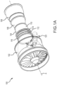
FIG. 1A provides a schematic perspective view of a gas turbine engine having a gearbox mounted to an external case of the gas turbine engine, in accordance with various embodiments; -
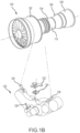
FIG. 1B provides a schematic exploded view of the gas turbine engine shown inFIG. 1A , and a gearbox mounting system for mounting the gearbox to the external case of the gas turbine engine, in accordance with various embodiments; -
FIG. 2A provides a schematic radial view of a gearbox mounting assembly, including a support bracket and a locator comprising a fusible guide pin and a catcher pin, mounted to a portion of an engine case, in accordance with various embodiments; -
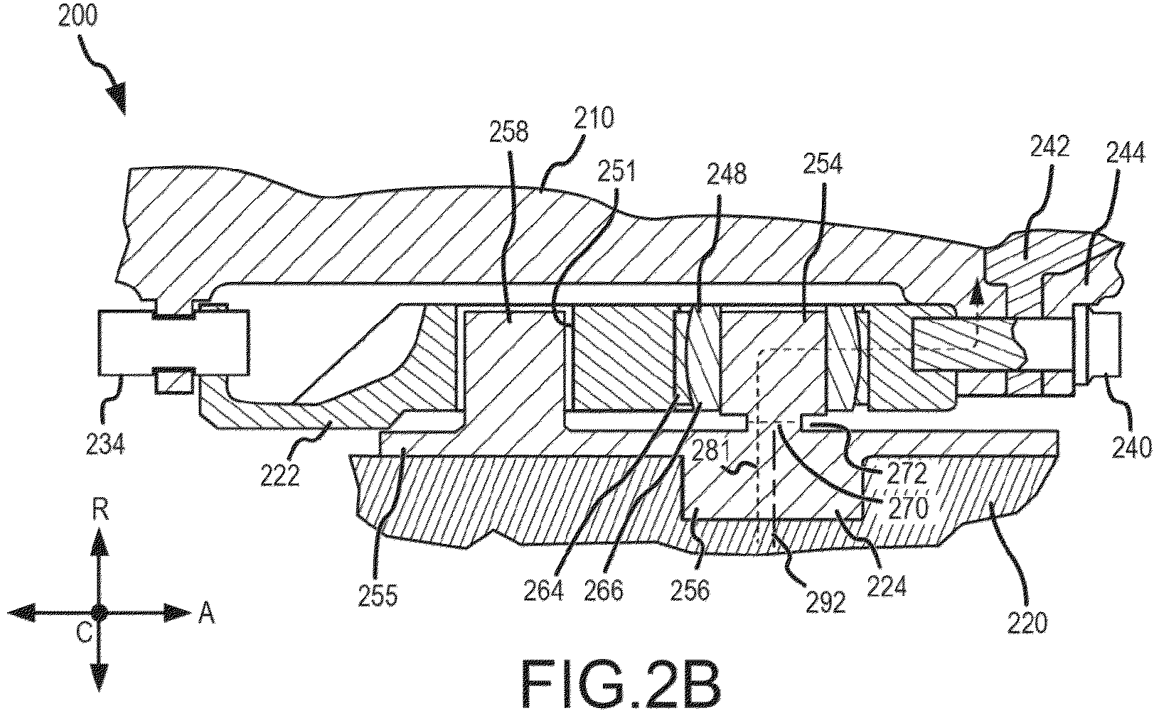
FIG. 2B provides a schematic side view of the gearbox mounting assembly shown inFIG. 2A , in accordance with various embodiments; and -
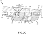
FIG. 2C provides a schematic side view of the gearbox mounting assembly shown inFIG. 2B , with a broken fusible guide pin, in accordance with various embodiments. - The following detailed description of various embodiments herein makes reference to the accompanying drawings, which show various embodiments by way of illustration. While these various embodiments are described in sufficient detail to enable those skilled in the art to practice the disclosure, it should be understood that other embodiments may be realized and that changes may be made without departing from the scope of the disclosure. Thus, the detailed description herein is presented for purposes of illustration only and not of limitation. Furthermore, any reference to singular includes plural embodiments, and any reference to more than one component or step may include a singular embodiment or step. Also, any reference to attached, fixed, connected, or the like may include permanent, removable, temporary, partial, full or any other possible attachment option. Additionally, any reference to without contact (or similar phrases) may also include reduced contact or minimal contact. It should also be understood that unless specifically stated otherwise, references to "a," "an" or "the" may include one or more than one and that reference to an item in the singular may also include the item in the plural. Further, all ranges may include upper and lower values and all ranges and ratio limits disclosed herein may be combined.
- The present disclosure provides, as part of a gearbox mounting system, a fusible center guide pin and a catcher pin. A fusible center guide pin of the present disclosure can mitigate/absorb energy transmitted to an auxiliary component, such as a gearbox housing, thereby reducing or eliminating the tendency for the auxiliary component (e.g., gearbox housing) to crack or fracture. In response to the fusible center guide pin breaking, the catcher pin can engage a support bracket to limit movement of the auxiliary component with respect to an engine case, thereby eliminating or reducing contact of the gearbox with adjacent components which could cause further damage. A gearbox mounting system of the present disclosure provides a low cost, low weight solution within the available design space.
- Referring now to the drawings,
FIG. 1A andFIG. 1B schematically illustrate agas turbine engine 100, in accordance with various embodiments. Thegas turbine engine 100 includes afan section 102, acompressor section 104, acombustor section 106 and aturbine section 108. Typically, thecompressor section 104 and theturbine section 108 each contain one or more stages that rotate about a central rotational axis A. Anengine case 110 serves as a main structural support for thegas turbine engine 100 and surrounds each of thecompressor section 104, thecombustor section 106 and theturbine section 108. In various embodiments, theengine case 110 is constructed of individual case sections, such as afirst case section 112 and asecond case section 114, that are joined together at bolted flanges, such as,flange 116. Agearbox 120 is illustrated as being mounted to a forward end of theengine case 110 proximate thecompressor section 104. Referring more particularly toFIG. 1B , thegearbox 120 is mounted to theengine case 110 via asupport bracket 122 and aguide pin 124 configured to maintain thegearbox 120 in proper alignment and position with respect to theengine case 110. In various embodiments, one ormore side links 126 and aforward link 128 may also be used to mount thegearbox 120 to theengine case 110. - Referring now to
FIG. 2A and FIG. 2B , schematic radial and section views, respectively, of agearbox mounting assembly 200 mounted to a portion of anengine case 210 are illustrated, in accordance with various embodiments. Any reference to the terms axis and axial may include axis A described above or a dimension parallel to such axis; though in various embodiments, the term axial refers to a centerline axis offirst member 254,second member 256, and/orthird member 258, as described herein. Axis A is oriented in the A direction (i.e., axial direction) on the provided ARC axes. The R direction on the provided ARC axes refers to a radial direction and the C direction on the provided ARC axes refers to a circumferential direction. Thegearbox mounting assembly 200 includes asupport bracket 222 and alocator 224. In various embodiments,support bracket 222 is disposed radially betweenlocator 224 andengine case 210. Stated differently,locator 224 may be disposed radially outward fromsupport bracket 222. In various embodiments, thesupport bracket 222 includes afirst end 230 configured for connection to afirst flange 232 of theengine case 210 via a first plurality ofbolts 234 and asecond end 236 configured for connection to asecond flange 238 of theengine case 210 via a second plurality ofbolts 240. In various embodiments, thesecond end 236 of thesupport bracket 222 may also be connected to additional flanges. For example, where theengine case 210 is a high-pressure compressor case, thesecond flange 238 may be positioned adjacent to an innerdiffuser case flange 242 and an outerdiffuser case flange 244. Thesupport bracket 222 also includes anintermediate portion 246 located intermediate thefirst end 230 and thesecond end 236 and configured to support a bearing member 248 (e.g., a spherical bearing).Intermediate portion 246 may define a firstcylindrical aperture 250 that extends into or through theintermediate portion 246 of thesupport bracket 222.Intermediate portion 246 may further define a secondcylindrical aperture 251 that extends into or through theintermediate portion 246 of thesupport bracket 222. In various embodiments, secondcylindrical aperture 251 can be disposed axially (with respect to the central rotational axis A described above) with respect to the firstcylindrical aperture 250. In various embodiments, secondcylindrical aperture 251 can be axially (with respect to the central rotational axis A described above) aligned with respect to the first cylindrical aperture 250 (i.e., aligned along cut-line 2B inFIG. 2A ). - In various embodiments, the
locator 224 includes a plate member 255 (seeFIG. 2B ) that may be mounted to the casing orhousing 220 of the auxiliary component (e.g., a casing of the gearbox 120). In various embodiments, theplate member 255 is bolted to thehousing 220. - In various embodiments, the
locator 224 further includes a first member 254 (e.g., a first cylindrical member; also referred to herein as a fusible guide pin) extending from theplate member 255.First member 254 may comprise a (center) guide pin for locating (e.g., centering) the auxiliary component with respect toengine case 210.First member 254 can be integrally formed withplate member 255. A first end offirst member 254 can be integrally attached toplate member 255 and a second end offirst member 254 may be free (i.e.,first member 254 may extend fromplate member 255 in a cantilevered fashion). - In various embodiments, bearing
member 248 may be press fit into firstcylindrical aperture 250. In various embodiments,first member 254 of thelocator 224 may be positioned and secured in the bearingmember 248. In various embodiments, a thirdcylindrical aperture 252 is defined by an inner diameter surface of bearingmember 248.First member 254 may be positioned and secured in the thirdcylindrical aperture 252. In various embodiments, the free end offirst member 254 is disposed at least partially into bearingmember 248. In various embodiments, bearingmember 248 comprises anouter race 264 and amoveable member 266 supported by, and moveable with respect to, theouter race 264.First member 254 may be coupled tomoveable member 266. In various embodiments,first member 254 and bearingmember 248 are coaxially located within firstcylindrical aperture 250.Bearing member 248 may allow nominal movement ofgearbox housing 220 with respect toengine case 210. - In various embodiments, the
locator 224 further includes a second member 256 (e.g., a second cylindrical member; also referred to herein as a third pin) configured for insertion into an aperture extending into a casing orhousing 220 of an auxiliary component (e.g., thegearbox 120 illustrated inFIG. 1A andFIG. 1B ).Second member 256 can be integrally formed withplate member 255.Second member 256 may be disposed oppositeplate member 255 fromfirst member 254. In various embodiments,second member 256 is coaxial withfirst member 254. In various embodiments,second member 256 is substantially coaxial withfirst member 254 such that loads resulting from side-to-side (i.e., along the circumferential direction of theengine case 210, with respect to the central rotational axis A described above) motion of the auxiliary component is transferred betweenfirst member 254 andsecond member 256 without imparting a moment or torque onplate member 255 about thecenterline axis 292 ofsecond member 256. In various embodiments,second member 256 andfirst member 254 are disposed parallel to one another (i.e., acenterline axis 292 of thesecond member 256 is parallel with a centerline axis of the first member 254). - In various embodiments, the
locator 224 further includes a third member 258 (e.g., a third cylindrical member; also referred to herein as a catcher pin) extending from theplate member 255.Third member 258 may comprise a catcher pin for limiting motion of the auxiliary component with respect toengine case 210 in the eventfirst member 254 fractures such that thefirst member 254 is no longer supporting the auxiliary component with respect to theengine case 210.Third member 258 can be integrally formed withplate member 255. In various embodiments,third member 258 andfirst member 254 are disposed parallel one another (i.e., a centerline axis of thethird member 258 is parallel with a centerline axis of the first member 254). In various embodiments, the centerline axis ofthird member 258 is oriented radially with respect to a central axis of the engine case 210 (i.e., with respect to the central rotational axis A described above). - Referring more particularly to
FIG. 2B , amechanical fuse 270 may be incorporated intofirst member 254. Themechanical fuse 270 is configured to break or fracture a portion of thefirst member 254 in the event of a FBO, for example, such that the auxiliary component (e.g., the gearbox 120) remains attached to theengine case 210. Themechanical fuse 270 extends through a portion offirst member 254 and is formed by anannular cut 272 that extends circumferentially about the radially outer portion of the at least one offirst member 254. As illustrated, in various embodiments, themechanical fuse 270 defines a diameter that is typically less than a nominal diameter offirst member 254. - With reference to
FIG. 2A and FIG. 2B , to accommodate movement of thelocator 224 following an overload event,third member 258 is configured to catch (or to hold substantially in place) thelocator 224 following fracture offirst member 254.Third member 258 may be positioned adjacent a radial inner surface ofsupport bracket 222 defining secondcylindrical aperture 251 such that a radial outer surface ofthird member 258 is configured to contact said radial inner surface ofsupport bracket 222. In various embodiments, secondcylindrical aperture 251 is oversized (i.e., comprises a diameter greater than the diameter of third member 258) such that thethird member 258 andsupport bracket 222 define an annular volume or void that separates thethird member 258 fromsupport bracket 222. In this manner, limited movement (perpendicular to axis 292) between thethird member 258 and the support bracket 222 (thereby allowing limited movement of the auxiliary component with respect to engine case 210) may be permitted following an overload event and the fracturing offirst member 254. The spacing betweenthird member 258 and secondcylindrical aperture 251 can be set to allow axial and circumferential motion of thegearbox 120 to be limited to prevent excessive motion which can allow substantial contact between gearbox mounted hardware and surrounding engine mounted hardware in the event of an FBO. - In various embodiments, the diameter of first member 254 (i.e., at mechanical fuse 270) is determined based on an ultimate shear strength calculated to be less than a predicted load expected during the overload event. In various embodiments, for example, the ultimate shear strength of
first member 254 is equal to a value within a range of 10% to 95% of the predicted overload; or, in various embodiments, the ultimate shear strength is equal to a value within a range of 25% to 90% of the predicted overload; or, in various embodiments, the ultimate shear strength is equal to a value within a range of 50% to 90% of the predicted overload; or, in various embodiments, the ultimate shear strength is equal to a value within a range of 70% to 80% of the predicted overload. In various embodiments, the shear strength offirst member 254 may be selected so that the ultimate strength offirst member 254 is less than the predicted overload - and low enough that the supported hardware survives the overload event, but high enough to withstand loads expected during normal operation and/or other loads which are less than those expected during a FBO event. The ultimate shear strength of thefirst member 254 is less than that of thesecond member 256. The ultimate shear strength of thefirst member 254 is less than that of thethird member 258. It should be understood that the ultimate shear strengths offirst member 254 andthird member 258 can be measured under similar conditions (e.g., room temperature or operating temperature) and measured in force divided by area. In SI, the unit is the pascal (Pa) or Newtons per square meter. In United States customary units, shear stress is also commonly measured in pounds-force per square inch or kilopounds-force per square inch. - With reference to
FIG. 2C ,gearbox mounting assembly 200 is illustrated after a FBO event and with thethird member 258 moved (i.e., axially with respect to the central rotational axis A described above, or radially with respect tocentral axis 294 of second cylindrical aperture 251) within secondcylindrical aperture 251 and themechanical fuse 270 offirst member 254 broken. In this regard, thecentral axis 295 ofthird member 258 can be moved radially with respect tocentral axis 294. After the FBO event, movement (i.e., left and right inFIG. 2C ) of locator 224 (and third member 258) may be permitted, while still maintainingthird member 258 captured within secondcylindrical aperture 251 to limit movement of thegearbox housing 220 with respect to engine case 210 (seeFIG. 2B ). In this regard, theouter diameter surface 259 of thethird member 258 is configured to contact theinner diameter surface 261 of secondcylindrical aperture 251 in response to an overload event andfirst member 254 breaking. - With reference to
FIG. 2B , prior tomechanical fuse 270 breaking (e.g., prior to an overload event) afirst load path 281 is formed fromgearbox housing 220, throughsecond member 256,plate member 255,first member 254, bearingmember 248,support bracket 222, and intoengine case 210 via first plurality ofbolts 234 and second plurality ofbolts 240. In this regard, prior tomechanical fuse 270 breaking, loads can be reacted betweengearbox housing 220 andengine case 210 viasecond member 256 andfirst member 254. Conversely, and with reference toFIG. 2C , aftermechanical fuse 270 breaks (e.g., during and/or after an overload event) a second load path 282 is formed fromgearbox housing 220, throughsecond member 256,plate member 255,third member 258,support bracket 222, and intoengine case 210 via first plurality ofbolts 234 and second plurality ofbolts 240. In this regard, aftermechanical fuse 270 breaks, loads can be reacted betweengearbox housing 220 andengine case 210 viasecond member 256 andthird member 258. - Various benefits of the foregoing disclosure may be realized. For example, the various embodiments provide a manner to maintain the axial degree of freedom of the locator in place by limiting movement of the support bracket to small distances in the radial and the axial directions following an overload event.
- Benefits, other advantages, and solutions to problems have been described herein with regard to specific embodiments. Furthermore, the connecting lines shown in the various figures contained herein are intended to represent exemplary functional relationships and/or physical couplings between the various elements. It should be noted that many alternative or additional functional relationships or physical connections may be present in a practical system. However, the benefits, advantages, solutions to problems, and any elements that may cause any benefit, advantage, or solution to occur or become more pronounced are not to be construed as critical, required, or essential features or elements of the disclosure. The scope of the disclosure is accordingly to be limited by nothing other than the appended claims, in which reference to an element in the singular is not intended to mean "one and only one" unless explicitly so stated, but rather "one or more." Moreover, where a phrase similar to "at least one of A, B, or C" is used in the claims, it is intended that the phrase be interpreted to mean that A alone may be present in an embodiment, B alone may be present in an embodiment, C alone may be present in an embodiment, or that any combination of the elements A, B and C may be present in a single embodiment; for example, A and B, A and C, B and C, or A and B and C. Different cross-hatching is used throughout the figures to denote different parts but not necessarily to denote the same or different materials.
- Systems, methods and apparatus are provided herein. In the detailed description herein, references to "one embodiment," "an embodiment," "various embodiments," etc., indicate that the embodiment described may include a particular feature, structure, or characteristic, but every embodiment may not necessarily include the particular feature, structure, or characteristic. Moreover, such phrases are not necessarily referring to the same embodiment. Further, when a particular feature, structure, or characteristic is described in connection with an embodiment, it is submitted that it is within the knowledge of one skilled in the art to affect such feature, structure, or characteristic in connection with other embodiments whether or not explicitly described. After reading the description, it will be apparent to one skilled in the relevant art(s) how to implement the disclosure in alternative embodiments.
- Furthermore, no element, component, or method step in the present disclosure is intended to be dedicated to the public regardless of whether the element, component, or method step is explicitly recited in the claims. No claim element herein is intended to invoke 35 U.S.C. 112(f) unless the element is expressly recited using the phrase "means for." As used herein, the terms "comprises," "comprising," or any other variation thereof, are intended to cover a non-exclusive inclusion, such that a process, method, article, or apparatus that comprises a list of elements does not include only those elements but may include other elements not expressly listed or inherent to such process, method, article, or apparatus.
- Numbers, percentages, or other values stated herein are intended to include that value, and also other values that are about or approximately equal to the stated value, as would be appreciated by one of ordinary skill in the art encompassed by various embodiments of the present disclosure. A stated value should therefore be interpreted broadly enough to encompass values that are at least close enough to the stated value to perform a desired function or achieve a desired result. The stated values include at least the variation to be expected in a suitable industrial process, and may include values that are within 10%, within 5%, within 1%, within 0.1%, or within 0.01% of a stated value. Additionally, the terms "substantially," "about" or "approximately" as used herein represent an amount close to the stated amount that still performs a desired function or achieves a desired result. For example, the term "substantially," "about" or "approximately" may refer to an amount that is within 10% of, within 5% of, within 1% of, within 0.1% of, and within 0.01% of a stated amount or value.
- Finally, any of the above-described concepts can be used alone or in combination with any of or all the other above-described concepts. Although various embodiments have been disclosed and described, one of ordinary skill in this art would recognize that certain modifications would come within the scope of this disclosure. Accordingly, the description is not intended to be exhaustive or to limit the principles described or illustrated herein to any precise form. Many modifications and variations are possible in light of the above teaching.
Claims (15)
- An assembly for mounting an auxiliary component to an engine case of a gas turbine engine, comprising:a support bracket, the support bracket having a first end configured for attachment to a first flange of the engine case, a second end configured for attachment to a second flange of the engine case, and an intermediate portion located intermediate the first end and the second end;a first aperture disposed in the intermediate portion;a second aperture disposed in the intermediate portion; anda locator comprising a plate member, a fusible guide pin extending from the plate member at least partially into the first aperture, and a catcher pin extending from the plate member at least partially into the second aperture.
- The assembly of claim 1, wherein the fusible guide pin comprises a mechanical fuse configured to break in response to an overload event.
- The assembly of claim 2, wherein the catcher pin is configured to limit movement of the locator with respect to the support bracket when the mechanical fuse is broken.
- The assembly of any preceding claim, comprising a bearing member disposed at least partially within the first aperture;
wherein the fusible guide pin is disposed at least partially within the bearing member. - The assembly of claim 4, wherein the bearing member is press fit at least partially into the support bracket; and/or
wherein the fusible guide pin is disposed at least partially within the bearing member. - The assembly of any preceding claim, wherein a first central axis of the fusible guide pin and a second central axis of the catcher pin are oriented radially with respect to the engine case.
- A gas turbine engine, comprising:an engine case, the engine case including a first flange and a second flange;a support bracket, the support bracket having a first end configured for attachment to the first flange of the engine case, a second end configured for attachment to the second flange of the engine case, and an intermediate portion located intermediate the first end and the second end;a first aperture disposed in the intermediate portion;a second aperture disposed in the intermediate portion; anda locator comprising a plate member, a fusible guide pin extending from the plate member at least partially into the first aperture, and a catcher pin extending from the plate member at least partially into the second aperture.
- The gas turbine engine of claim 7, wherein the fusible guide pin comprises a mechanical fuse configured to break in response to an overload event, and the catcher pin is configured to limit movement of the locator with respect to the support bracket when the mechanical fuse is broken.
- The gas turbine engine of claim 7 or 8, further comprising a bearing member disposed at least partially within the first aperture;
wherein the fusible guide pin is disposed at least partially within the bearing member. - The gas turbine engine of claim 9, wherein the bearing member is press fit at least partially into the support bracket, and the fusible guide pin is disposed at least partially within the bearing member.
- The assembly of any of claims 1 to 6 or the gas turbine engine of any of claims 7 to 10, wherein a first diameter of the second aperture is greater than a second diameter of the catcher pin.
- The assembly of claim 11 or the gas turbine engine of claim 11, wherein the second aperture is oversized to allow radial movement, with respect to a central axis of the second aperture, of the catcher pin within the second aperture.
- The assembly of any of claims 1 to 6 or 11 to 12, or the gas turbine engine of any of claims 7 to 12, further comprising a third pin extending from the plate member and configured to be received by an auxiliary component for the gas turbine engine.
- The assembly of claim 13 or the gas turbine engine of claim 13, wherein the third pin extends from the plate member in a direction opposite the fusible guide pin and the catcher pin.
- A locator for mounting an auxiliary component to an engine case of a gas turbine engine, comprising:a plate member;a fusible guide pin extending from the plate member in a first direction;a catcher pin extending from the plate member in the first direction; anda third pin extending from the plate member in a second direction, opposite the first direction;wherein the third pin is disposed substantially coaxially with the fusible guide pin.
Applications Claiming Priority (1)
| Application Number | Priority Date | Filing Date | Title |
|---|---|---|---|
| US18/297,577 US12209539B2 (en) | 2023-04-07 | 2023-04-07 | Fusible gearbox support with catcher pin systems and methods |
Publications (1)
| Publication Number | Publication Date |
|---|---|
| EP4442968A1 true EP4442968A1 (en) | 2024-10-09 |
Family
ID=90482458
Family Applications (1)
| Application Number | Title | Priority Date | Filing Date |
|---|---|---|---|
| EP24166544.7A Pending EP4442968A1 (en) | 2023-04-07 | 2024-03-26 | Assembly for mounting an auxiliary component to an engine case of a gas turbine engine, gas turbine engine and locator for mounting an auxiliary component to an engine case of a gas turbine engine |
Country Status (2)
| Country | Link |
|---|---|
| US (1) | US12209539B2 (en) |
| EP (1) | EP4442968A1 (en) |
Citations (2)
| Publication number | Priority date | Publication date | Assignee | Title |
|---|---|---|---|---|
| US20230057017A1 (en) * | 2021-08-20 | 2023-02-23 | Raytheon Technologies Corporation | Auxiliary component mounting system for gas turbine engines |
| US20230105543A1 (en) * | 2021-10-01 | 2023-04-06 | Raytheon Technologies Corporation | Auxiliary component mounting system for gas turbine engines |
Family Cites Families (27)
| Publication number | Priority date | Publication date | Assignee | Title |
|---|---|---|---|---|
| DE69012071T2 (en) * | 1989-12-05 | 1995-04-13 | Rolls Royce Plc | Fail-safe holding device for engines. |
| US5303880A (en) * | 1992-10-28 | 1994-04-19 | General Electric Company | Aircraft engine pin mount |
| US6170252B1 (en) * | 1998-12-14 | 2001-01-09 | United Technologies Corporation | Locator for a gearbox mount |
| US7494317B2 (en) | 2005-06-23 | 2009-02-24 | Siemens Energy, Inc. | Ring seal attachment system |
| GB201009548D0 (en) * | 2010-06-08 | 2010-07-21 | Rolls Royce Plc | A mounting assembly |
| US8573922B2 (en) | 2010-06-15 | 2013-11-05 | Rolls-Royce Corporation | Bearing support |
| US8561501B2 (en) * | 2011-05-31 | 2013-10-22 | United Technologies Corporation | Gearbox mount bracket |
| US20130042630A1 (en) | 2011-08-19 | 2013-02-21 | United Technologies Corporation | Gas turbine engine accessory mount |
| US9046041B2 (en) * | 2012-09-25 | 2015-06-02 | Pratt & Whitney Canada Corp. | Gearbox positioning device |
| US9500133B2 (en) | 2012-12-23 | 2016-11-22 | United Technologies Corporation | Mount with an axial upstream linkage for connecting a gearbox to a turbine engine case |
| US9777639B2 (en) * | 2012-12-23 | 2017-10-03 | United Technologies Corporation | Turbine engine gearbox mount with multiple fuse joints |
| EP2964936A4 (en) * | 2013-03-08 | 2016-11-02 | United Technologies Corp | Gearbox mounting assembly |
| US9958217B1 (en) | 2013-06-19 | 2018-05-01 | Nooter/Eriksen, Inc. | Baffle system and method for a heat exchanger located within a casing of a heat recovery steam generator |
| WO2015042089A1 (en) | 2013-09-23 | 2015-03-26 | United Technologies Corporation | Method of generating support structure of tube components to become functional features |
| WO2015053940A1 (en) | 2013-10-07 | 2015-04-16 | United Technologies Corporation | Additively grown enhanced impact resistance features for improved structure and joint protection |
| US9605562B2 (en) * | 2015-02-09 | 2017-03-28 | United Techologies Corporation | Turbomachine accessory gearbox alignment pin |
| FR3062439B1 (en) | 2017-02-02 | 2019-03-15 | Safran Transmission Systems | INTEGRATED FILTER TURBOMACHINE CAP AND METHOD FOR PRODUCING THE SAME |
| US10774008B2 (en) | 2017-09-21 | 2020-09-15 | General Electric Company | Ceramic matrix composite articles |
| US11479104B2 (en) | 2019-07-24 | 2022-10-25 | Honeywell International Inc. | System and method for gas turbine engine mount with seal |
| US11261757B2 (en) * | 2019-12-05 | 2022-03-01 | Pratt & Whitney Canada Corp. | Boss for gas turbine engine |
| US11066947B2 (en) | 2019-12-18 | 2021-07-20 | Rolls-Royce Corporation | Turbine shroud assembly with sealed pin mounting arrangement |
| US11230937B2 (en) | 2020-05-18 | 2022-01-25 | Rolls-Royce North American Technologies Inc. | Turbine shroud assembly with dovetail retention system |
| US11215080B1 (en) | 2020-11-18 | 2022-01-04 | Rolls-Royce Corporation | Turbine shroud assembly with integrated ceramic matrix composite component support pins |
| US11674449B2 (en) | 2021-03-12 | 2023-06-13 | Pratt & Whitney Canada Corp. | Mount assembly for accessory gearbox of aircraft engine and associated method of assembly |
| US11319828B1 (en) | 2021-06-18 | 2022-05-03 | Rolls-Royce Corporation | Turbine shroud assembly with separable pin attachment |
| US11499444B1 (en) | 2021-06-18 | 2022-11-15 | Rolls-Royce Corporation | Turbine shroud assembly with forward and aft pin shroud attachment |
| US11441441B1 (en) | 2021-06-18 | 2022-09-13 | Rolls-Royce Corporation | Turbine shroud with split pin mounted ceramic matrix composite blade track |
-
2023
- 2023-04-07 US US18/297,577 patent/US12209539B2/en active Active
-
2024
- 2024-03-26 EP EP24166544.7A patent/EP4442968A1/en active Pending
Patent Citations (2)
| Publication number | Priority date | Publication date | Assignee | Title |
|---|---|---|---|---|
| US20230057017A1 (en) * | 2021-08-20 | 2023-02-23 | Raytheon Technologies Corporation | Auxiliary component mounting system for gas turbine engines |
| US20230105543A1 (en) * | 2021-10-01 | 2023-04-06 | Raytheon Technologies Corporation | Auxiliary component mounting system for gas turbine engines |
Also Published As
| Publication number | Publication date |
|---|---|
| US20240337217A1 (en) | 2024-10-10 |
| US12209539B2 (en) | 2025-01-28 |
Similar Documents
| Publication | Publication Date | Title |
|---|---|---|
| EP4163483B1 (en) | Auxiliary component mounting system for gas turbine engines | |
| EP4137672A1 (en) | Auxiliary component mounting system for gas turbine engines | |
| EP2559883B1 (en) | Gas turbine engine gearbox mount | |
| EP1382805B1 (en) | Frangible coupling | |
| EP1010878B1 (en) | Gas turbine engine having a variable stiffness positioning link for a gearbox | |
| JP3786622B2 (en) | Turbine engine | |
| EP1473441B1 (en) | Apparatus for mounting a gas turbine engine | |
| EP3219962B1 (en) | One degree-of-constraint semi-fusible gearbox mounting link | |
| US10215100B2 (en) | One degree-of-constraint semi-fusible gearbox mounting link | |
| EP3287624B1 (en) | Boss-mounted gearbox link comprising a bracket with an integrated shear neck | |
| JP2000186575A (en) | Gas turbine engine | |
| JP2000179358A (en) | Gearbox locator | |
| EP3219961B1 (en) | Two degree-of-constraint semi-fusible gearbox mounting link | |
| US10344806B2 (en) | Shaft assembly comprising a frangible coupling and a flexible coupling | |
| EP4083434A1 (en) | Cabin air compressor shaft and tie rod support | |
| EP4442969A1 (en) | Assembly for mounting an auxiliary component to an engine case of a gas turbine engine, gas turbine engine and locator for mounting an auxiliary component to an engine case of a gas turbine engine | |
| CN111894737B (en) | Rotor support structure and gas turbine | |
| EP4442968A1 (en) | Assembly for mounting an auxiliary component to an engine case of a gas turbine engine, gas turbine engine and locator for mounting an auxiliary component to an engine case of a gas turbine engine | |
| EP4137673A1 (en) | Laterally biased system for mounting auxiliary components to gas turbine engines | |
| EP4303421A1 (en) | Auxiliary component movement restriction mounting system for gas turbine engines | |
| EP3683148B1 (en) | Mounting apparatus for a gas turbine engine | |
| US12479586B2 (en) | Fusible mounting assembly for gas turbine engine | |
| CN116181426A (en) | Bearing housing for a gas turbine engine |
Legal Events
| Date | Code | Title | Description |
|---|---|---|---|
| PUAI | Public reference made under article 153(3) epc to a published international application that has entered the european phase |
Free format text: ORIGINAL CODE: 0009012 |
|
| STAA | Information on the status of an ep patent application or granted ep patent |
Free format text: STATUS: THE APPLICATION HAS BEEN PUBLISHED |
|
| AK | Designated contracting states |
Kind code of ref document: A1 Designated state(s): AL AT BE BG CH CY CZ DE DK EE ES FI FR GB GR HR HU IE IS IT LI LT LU LV MC ME MK MT NL NO PL PT RO RS SE SI SK SM TR |
|
| STAA | Information on the status of an ep patent application or granted ep patent |
Free format text: STATUS: REQUEST FOR EXAMINATION WAS MADE |
|
| 17P | Request for examination filed |
Effective date: 20250331 |
|
| GRAP | Despatch of communication of intention to grant a patent |
Free format text: ORIGINAL CODE: EPIDOSNIGR1 |
|
| RIC1 | Information provided on ipc code assigned before grant |
Ipc: F01D 21/04 20060101AFI20251217BHEP Ipc: F01D 25/28 20060101ALI20251217BHEP Ipc: F02C 7/20 20060101ALN20251217BHEP Ipc: F02C 7/32 20060101ALN20251217BHEP |
|
| STAA | Information on the status of an ep patent application or granted ep patent |
Free format text: STATUS: GRANT OF PATENT IS INTENDED |
|
| INTG | Intention to grant announced |
Effective date: 20260122 |