EP4442941A1 - Wireless apparatus and method for controlling wireless apparatus - Google Patents
Wireless apparatus and method for controlling wireless apparatus Download PDFInfo
- Publication number
- EP4442941A1 EP4442941A1 EP22900922.0A EP22900922A EP4442941A1 EP 4442941 A1 EP4442941 A1 EP 4442941A1 EP 22900922 A EP22900922 A EP 22900922A EP 4442941 A1 EP4442941 A1 EP 4442941A1
- Authority
- EP
- European Patent Office
- Prior art keywords
- phase
- signal
- difference
- distance measuring
- unit
- Prior art date
- Legal status (The legal status is an assumption and is not a legal conclusion. Google has not performed a legal analysis and makes no representation as to the accuracy of the status listed.)
- Pending
Links
Images


Classifications
-
- G—PHYSICS
- G01—MEASURING; TESTING
- G01S—RADIO DIRECTION-FINDING; RADIO NAVIGATION; DETERMINING DISTANCE OR VELOCITY BY USE OF RADIO WAVES; LOCATING OR PRESENCE-DETECTING BY USE OF THE REFLECTION OR RERADIATION OF RADIO WAVES; ANALOGOUS ARRANGEMENTS USING OTHER WAVES
- G01S11/00—Systems for determining distance or velocity not using reflection or reradiation
- G01S11/02—Systems for determining distance or velocity not using reflection or reradiation using radio waves
- G01S11/10—Systems for determining distance or velocity not using reflection or reradiation using radio waves using Doppler effect
-
- G—PHYSICS
- G01—MEASURING; TESTING
- G01S—RADIO DIRECTION-FINDING; RADIO NAVIGATION; DETERMINING DISTANCE OR VELOCITY BY USE OF RADIO WAVES; LOCATING OR PRESENCE-DETECTING BY USE OF THE REFLECTION OR RERADIATION OF RADIO WAVES; ANALOGOUS ARRANGEMENTS USING OTHER WAVES
- G01S11/00—Systems for determining distance or velocity not using reflection or reradiation
- G01S11/02—Systems for determining distance or velocity not using reflection or reradiation using radio waves
-
- B—PERFORMING OPERATIONS; TRANSPORTING
- B60—VEHICLES IN GENERAL
- B60R—VEHICLES, VEHICLE FITTINGS, OR VEHICLE PARTS, NOT OTHERWISE PROVIDED FOR
- B60R25/00—Fittings or systems for preventing or indicating unauthorised use or theft of vehicles
- B60R25/01—Fittings or systems for preventing or indicating unauthorised use or theft of vehicles operating on vehicle systems or fittings, e.g. on doors, seats or windscreens
-
- B—PERFORMING OPERATIONS; TRANSPORTING
- B60—VEHICLES IN GENERAL
- B60R—VEHICLES, VEHICLE FITTINGS, OR VEHICLE PARTS, NOT OTHERWISE PROVIDED FOR
- B60R25/00—Fittings or systems for preventing or indicating unauthorised use or theft of vehicles
- B60R25/20—Means to switch the anti-theft system on or off
- B60R25/24—Means to switch the anti-theft system on or off using electronic identifiers containing a code not memorised by the user
-
- E—FIXED CONSTRUCTIONS
- E05—LOCKS; KEYS; WINDOW OR DOOR FITTINGS; SAFES
- E05B—LOCKS; ACCESSORIES THEREFOR; HANDCUFFS
- E05B49/00—Electric permutation locks; Circuits therefor ; Mechanical aspects of electronic locks; Mechanical keys therefor
-
- G—PHYSICS
- G01—MEASURING; TESTING
- G01S—RADIO DIRECTION-FINDING; RADIO NAVIGATION; DETERMINING DISTANCE OR VELOCITY BY USE OF RADIO WAVES; LOCATING OR PRESENCE-DETECTING BY USE OF THE REFLECTION OR RERADIATION OF RADIO WAVES; ANALOGOUS ARRANGEMENTS USING OTHER WAVES
- G01S11/00—Systems for determining distance or velocity not using reflection or reradiation
- G01S11/02—Systems for determining distance or velocity not using reflection or reradiation using radio waves
- G01S11/04—Systems for determining distance or velocity not using reflection or reradiation using radio waves using angle measurements
-
- H—ELECTRICITY
- H04—ELECTRIC COMMUNICATION TECHNIQUE
- H04B—TRANSMISSION
- H04B1/00—Details of transmission systems, not covered by a single one of groups H04B3/00 - H04B13/00; Details of transmission systems not characterised by the medium used for transmission
- H04B1/38—Transceivers, i.e. devices in which transmitter and receiver form a structural unit and in which at least one part is used for functions of transmitting and receiving
- H04B1/3822—Transceivers, i.e. devices in which transmitter and receiver form a structural unit and in which at least one part is used for functions of transmitting and receiving specially adapted for use in vehicles
-
- H—ELECTRICITY
- H04—ELECTRIC COMMUNICATION TECHNIQUE
- H04B—TRANSMISSION
- H04B1/00—Details of transmission systems, not covered by a single one of groups H04B3/00 - H04B13/00; Details of transmission systems not characterised by the medium used for transmission
- H04B1/59—Responders; Transponders
-
- H—ELECTRICITY
- H04—ELECTRIC COMMUNICATION TECHNIQUE
- H04W—WIRELESS COMMUNICATION NETWORKS
- H04W12/00—Security arrangements; Authentication; Protecting privacy or anonymity
- H04W12/12—Detection or prevention of fraud
- H04W12/121—Wireless intrusion detection systems [WIDS]; Wireless intrusion prevention systems [WIPS]
- H04W12/122—Counter-measures against attacks; Protection against rogue devices
-
- H—ELECTRICITY
- H04—ELECTRIC COMMUNICATION TECHNIQUE
- H04W—WIRELESS COMMUNICATION NETWORKS
- H04W12/00—Security arrangements; Authentication; Protecting privacy or anonymity
- H04W12/60—Context-dependent security
- H04W12/63—Location-dependent; Proximity-dependent
-
- G—PHYSICS
- G01—MEASURING; TESTING
- G01S—RADIO DIRECTION-FINDING; RADIO NAVIGATION; DETERMINING DISTANCE OR VELOCITY BY USE OF RADIO WAVES; LOCATING OR PRESENCE-DETECTING BY USE OF THE REFLECTION OR RERADIATION OF RADIO WAVES; ANALOGOUS ARRANGEMENTS USING OTHER WAVES
- G01S2205/00—Position-fixing by co-ordinating two or more direction or position line determinations; Position-fixing by co-ordinating two or more distance determinations
- G01S2205/01—Position-fixing by co-ordinating two or more direction or position line determinations; Position-fixing by co-ordinating two or more distance determinations specially adapted for specific applications
-
- G—PHYSICS
- G01—MEASURING; TESTING
- G01S—RADIO DIRECTION-FINDING; RADIO NAVIGATION; DETERMINING DISTANCE OR VELOCITY BY USE OF RADIO WAVES; LOCATING OR PRESENCE-DETECTING BY USE OF THE REFLECTION OR RERADIATION OF RADIO WAVES; ANALOGOUS ARRANGEMENTS USING OTHER WAVES
- G01S5/00—Position-fixing by co-ordinating two or more direction or position line determinations; Position-fixing by co-ordinating two or more distance determinations
- G01S5/02—Position-fixing by co-ordinating two or more direction or position line determinations; Position-fixing by co-ordinating two or more distance determinations using radio waves
- G01S5/0284—Relative positioning
-
- Y—GENERAL TAGGING OF NEW TECHNOLOGICAL DEVELOPMENTS; GENERAL TAGGING OF CROSS-SECTIONAL TECHNOLOGIES SPANNING OVER SEVERAL SECTIONS OF THE IPC; TECHNICAL SUBJECTS COVERED BY FORMER USPC CROSS-REFERENCE ART COLLECTIONS [XRACs] AND DIGESTS
- Y02—TECHNOLOGIES OR APPLICATIONS FOR MITIGATION OR ADAPTATION AGAINST CLIMATE CHANGE
- Y02D—CLIMATE CHANGE MITIGATION TECHNOLOGIES IN INFORMATION AND COMMUNICATION TECHNOLOGIES [ICT], I.E. INFORMATION AND COMMUNICATION TECHNOLOGIES AIMING AT THE REDUCTION OF THEIR OWN ENERGY USE
- Y02D30/00—Reducing energy consumption in communication networks
- Y02D30/70—Reducing energy consumption in communication networks in wireless communication networks
Definitions
- the present disclosure relates to a wireless device and a method for controlling the wireless device.
- a master wireless device that transmits a synchronization signal to a slave wireless device
- the synchronization signal includes timing information
- the timing information includes a common time reference and a time slot duration for coordinating master and slave communication time slots so that alternating TX and RX roll patterns are provided to the master and to the slave.
- the master analyzes slave packet data received from the slave to identify an overlap of transmissions from the master and slave packet data, which is a packet error, and in the case of the packet error, the communication from the master to the slave is interrupted to prevent a relay attack (for example, see Patent Document 1).
- Patent Document 1 Japanese National Publication of International Patent Application No. 2019-533096
- the packet error is detected by using a common time reference and a time slot duration for coordinating the master and slave communication time slots. Therefore, for example, in a case where a master device serving as "master” changes a phase of a transmission signal to be transmitted to a slave device serving as "slave", if an illegitimate slave device receives a transmission signal and impersonates a legitimate slave device by changing a phase of the transmission signal, the illegitimate slave device cannot be detected.
- the relay attack method for changing the phase of the transmission signal and impersonating a legitimate slave device is called early detect late commitment (EDLC).
- a wireless device includes a transmitter configured to transmit a signal to another device; a receiver configured to receive a signal from the another device; a difference calculating unit configured to obtain a first difference of a predetermined physical quantity, in a unit time, of a predetermined-frequency signal transmitted by the transmitter to the another device, and calculate a second difference of the predetermined physical quantity, in the unit time, of the predetermined-frequency signal received by the another device, based on the signal received by the receiver; and a determining unit configured to perform a determination process of comparing the first difference and the second difference to determine legitimacy of the signal received by the receiver.
- a wireless device that can detect a relay attack of impersonating a legitimate device by changing a phase of a reception signal, and a method for controlling the wireless device can be provided.
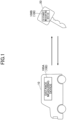
- FIG. 1 is a diagram illustrating a vehicle 10 and a smart key 20 in which distance measuring devices 100A and 100B including wireless devices according to the embodiment are implemented, respectively.
- the distance measuring devices 100A and 100B perform packet communication by Bluetooth Low Energy (BLE), for example.
- BLE Bluetooth Low Energy
- At least either the distance measuring device 100A of the vehicle 10 or the distance measuring device 100B of the smart key 20 measures a distance between the vehicle 10 and the smart key 20, and locks of a door, a trunk, and the like of the vehicle 10 are unlocked when the distance measured by the distance measuring device 100A or 100B is an appropriate distance.
- the distance measuring device 100A of the vehicle 10 performs distance measuring, and notifies the distance measuring device 100B of the smart key 20 of a result of the distance measuring.
- the distance measuring devices 100A and 100B have the same configuration, as an example. Therefore, in the following description, when the distance measuring devices 100A and 100B are not distinguished, they are simply referred to as a distance measuring device 100.
- the distance measuring device 100B that does not perform distance measuring among the distance measuring device 100A of the vehicle 10 and the distance measuring device 100B of the smart key 20 is an example of another device.
- the distance measuring device 100A as a master device and the distance measuring device 100B as a slave device, or conversely, to handle the distance measuring device 100B as a master device and the distance measuring device 100A as a slave device, but here, description will be given without such handling.
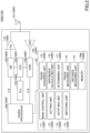
- FIG. 2 is a diagram illustrating the distance measuring device 100A of the embodiment.
- the distance measuring device 100A of the vehicle 10 and the distance measuring device 100B of the smart key 20 have the same configuration.
- the distance measuring device 100A that performs the distance measuring will be described.
- the distance measuring device 100A includes a wireless device 100R of the embodiment.
- the components included in the wireless device 100R are denoted by a reference symbol 100R in parentheses.
- the distance measuring device 100A includes an antenna 101, a power amplifier (PA) 110, a low noise amplifier (LNA) 120, an orthogonal modulator (OM) 130, an orthogonal demodulator (ODM) 140, a voltage controlled oscillator (VCO) 150, a phase locked loop (PLL) 155, a codec processor 160, and a control device 170.
- the wireless device 100R includes components other than a phase measuring unit 178 and a distance measuring unit 179 of the control device 170 among the components of the distance measuring device 100A. Therefore, the reference symbol 100R is written in parentheses for the components other than the phase measuring unit 178 and the distance measuring unit 179 of the control device 170 among the components of the distance measuring device 100A.
- the antenna 101 performs communication with the antenna 101 of the distance measuring device 100B smart key 20.
- the antenna 101 is connected to the PA 110 and the LNA 120.
- a switch for switching the connection destination of the antenna 101 to either the PA 110 or the LNA 120 is omitted.
- the PA 110 is provided between the OM 130 and the antenna 101, and amplifies a modulated signal for transmission that is input from the OM 130 and outputs the amplified signal to the antenna 101.
- the PA 110 is an amplifier for transmission.
- the LNA 120 is provided between the antenna 101 and the ODM 140, and amplifies a radio wave received by the antenna 101 with low noise and outputs the amplified radio wave to the ODM 140.
- the LNA 120 is an amplifier for reception.
- the OM 130 is an example of a transmitter, and modulates an I/Q signal input from the codec processor 160 by using a high-frequency signal input from the VCO 150, and outputs the modulated signal to the PA 110 as a modulated signal for transmission.
- the ODM 140 is an example of a receiver, and demodulates a signal output from the LNA 120 by using a high-frequency signal input from the VCO 150 to obtain the I/Q signal, and outputs the I/Q signal to the codec processor 160.
- the signal output from the LNA 120 is a signal received by the distance measuring device 100A from the distance measuring device 100B.
- the VCO 150 oscillates at the frequency set by the PLL 155.
- the VCO 150 can oscillate at multiple frequencies set by the PLL 155.
- the PLL 155 sets the frequency at which the VCO 150 oscillates.
- the PLL 155 can set multiple frequencies in the VCO 150.
- the codec processor 160 includes an analog to digital converter (ADC) and a digital to analog converter (DAC), and performs codec processing.
- the codec processor 160 performs detection of a BLE (registered trademark) packet, address determination processing, and the like. More specifically, the codec processor 160 performs digital conversion (ADC processing) on the I/Q signal processed in the ODM 140, and converts the I/Q signal into the packet information of BLE. Additionally, the codec processor 160 generates the I/Q signal (divides an I signal and a Q signal) from a BLE packet (digital signal) input from the control device 170, converts the I/Q signal into an analog signal by DAC processing, and outputs the analog signal to the OM 130 as the I/Q signal serving as a transmission signal.
- ADC analog to digital converter
- DAC digital to analog converter
- a predetermined-frequency signal that is transmitted from the OM 130 of the distance measuring device 100A to the distance measuring device 100B is referred to as a transmission signal.
- a signal transmitted as the transmission signal by the distance measuring device 100A and received by another device is referred to as a reception signal.
- the control device 170 includes a main control unit 171, a setting unit 172, a notifying unit 173, a switching unit 174, a phase acquiring unit 175, a difference calculating unit 176, a determining unit 177, the phase measuring unit 178, the distance measuring unit 179, and a memory 170M.
- the memory 170M is an example of a storage unit.
- the control device 170 is implemented by a microcomputer including a central processing unit (CPU), a random access memory (RAM), a read only memory (ROM), an input/output interface, an internal bus, and the like.
- the main control unit 171, the setting unit 172, the notifying unit 173, the switching unit 174, the phase acquiring unit 175, the difference calculating unit 176, the determining unit 177, the phase measuring unit 178, and the distance measuring unit 179 indicate functions of a program executed by the control device 170 as functional blocks. Additionally, the memory 170M functionally represents a memory of the control device 170.
- the main control unit 171 is a processing unit that controls processing of the control device 170, and performs processing other than processing performed by the setting unit 172, the notifying unit 173, the switching unit 174, the phase acquiring unit 175, the difference calculating unit 176, the determining unit 177, the phase measuring unit 178, and the distance measuring unit 179.
- the setting unit 172 sets the frequency (the predetermined frequency) and the phase of the signal to be transmitted from the distance measuring device 100A to the distance measuring device 100B. Additionally, the distance measuring device 100B transmits, to the distance measuring device 100A, a signal having a frequency the same as the frequency of the signal transmitted to the distance measuring device 100A.
- the same frequency of the signal transmitted by the distance measuring devices 100A and 100B to each other may be determined in advance between the distance measuring devices 100A and 100B. Data representing the frequency may be shared by using the BLE packet communication.
- the notifying unit 173 notifies the notifying unit 173 of the distance measuring device 100B in the smart key 20 of the result of the distance measuring.
- a BLE packet communication having a frequency different from that of the communication for the distance measuring is used.
- the result of the distance measuring and the like may be written in a payload of the BLE packet.
- the switching unit 174 switches between a transmission state in which the OM 130 transmits the signal and a reception state in which the ODM 140 receives the signal.
- the switching unit 174 allows the PA 110 to amplify the signal in the transmission state and allows the LNA to amplify the signal in the reception state.
- the switching unit 174 provides a stabilization time for stabilizing the phase and the frequency when switching between the transmission state and the reception state.
- the phase acquiring unit 175 acquires, from the distance measuring device 100B, the phase when the distance measuring device 100B receives the predetermined-frequency transmission signal that is transmitted by the distance measuring device 100A, as the reception signal.
- the phase acquiring unit 175 acquires data representing the phase from the distance measuring device 100B by the BLE packet communication having a frequency different from that of the communication for the distance measuring.
- the data representing the phase may be written in the payload of the BLE packet. Additionally, the data representing the phase may be measured by the phase measuring unit 178 of the distance measuring device 100B and transmitted to the distance measuring device 100A.
- the difference calculating unit 176 obtains a first difference of the phase of the predetermined-frequency transmission signal transmitted by the OM 130 to the distance measuring device 100B, and calculates a second difference of the phase of the predetermined-frequency reception signal received by another device, using the data representing the phase acquired by the phase acquiring unit 175 based on the signal received by the ODM 140.
- the phase is an example of a predetermined physical quantity.
- the distance measuring device 100B is a legitimate device having legitimate access authority to the distance measuring device 100A.
- the illegitimate device is a device that impersonates the distance measuring device 100B, which is the legitimate device, and is a device that does not have legitimate access authority to the distance measuring device 100A.
- the first difference and the second difference are used when determining the legitimacy of the device that is a transmission source having transmitted the signal received by the ODM 140. Methods for calculating the first difference and the second difference will be described later with reference to FIG. 3 and FIG. 4 .
- the determining unit 177 performs a determination process of comparing the first difference and the second difference calculated by the difference calculating unit 176, to determine the legitimacy of the signal received by the ODM 140.
- the determination of the legitimacy by the determining unit 177 indicates that the determining unit 177 determines the legitimacy of the device that is the transmission source having transmitted the signal received by the ODM 140. More specifically, the determining unit 177 determines whether the transmission source is the distance measuring device 100B or the illegitimate device impersonating the distance measuring device 100B.
- the phase measuring unit 178 measures the phase when the distance measuring device 100A receives the predetermined-frequency signal from the distance measuring device 100B. This phase is measured for distance measuring. Therefore, the phase measuring unit 178 is not included in the components of the wireless device 100R.
- the distance measuring unit 179 performs the distance measuring of the distance between the distance measuring device 100A and the distance measuring device 100B based on the phase of the transmission signal acquired by the phase acquiring unit 175, the phase measured by the phase measuring unit 178, and the number of waves of the transmission signal and the reception signal between the distance measuring device 100A and the distance measuring device 100B.
- the memory 170M stores programs, data, and the like that are necessary for the main control unit 171, the setting unit 172, the notifying unit 173, the switching unit 174, the phase acquiring unit 175, the difference calculating unit 176, the determining unit 177, the phase measuring unit 178, and the distance measuring unit 179 of the control device 170 to perform the above-described processing.
- the memory 170M stores data and the like in which the predetermined frequency and phases of the signals to be transmitted to each other between the distance measuring devices 100A and 100B are set.
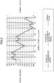
- FIG. 3 is a graph for explaining the phase of the transmission signal and the phase of the illegitimate reception signal.
- the illegitimate reception signal is a reception signal whose phase is falsified by the illegitimate device.
- the horizontal axis represents a sample point (0.25 ps/point) at which sampling is performed
- the vertical axis on the left side represents the phase (the degree)
- the vertical axis on the right side represents a symbol value (0 or 1).
- the horizontal axis represents the sample point, and thus corresponds to a time axis.
- the dash-dotted line indicates a symbol value (transmission symbol) of a BLE (registered trademark) packet (a digital signal) input from the control device 170 to the codec processor 160. Additionally, the solid line indicates the phase of the transmission signal, and the dashed line indicates the phase of the illegitimate reception signal.
- the phase of the I/Q signal as the transmission signal generated based on the BLE packet changes as indicated by the solid line.
- the phase of the reception signal of the legitimate distance measuring device 100B changes following the phase of the transmission signal indicated by the solid line, and therefore, has a waveform in which the reception signal is delayed by one sample point to several sample points with respect to the transmission signal.
- the phase of the illegitimate reception signal indicated by the dashed line in FIG. 3 represents an example of the phase of the illegitimate reception signal that can be generated by a relay attack method called EDLC, for example.
- the EDLC is a method for estimating a transmission symbol of a reception signal, generating a reception signal having a phase rise timing earlier than that of the reception signal based on the estimated transmission symbol, storing it in a payload of a BLE packet, and transmitting the reception signal to the distance measuring device 100A.
- the EDLC attempts to perform a relay attack by falsifying the phase, causing the distance measuring device 100A to incorrectly calculate the distance between the illegitimate device and the distance measuring device 100A, and impersonating the legitimate distance measuring device 100B.
- the phase of the illegitimate reception signal generated by the EDLC changes sharply so as to follow the symbol value of the BLE packet, and consequently, the phase of the illegitimate reception signal has a pattern that also follows the phase of the transmission signal. If the phase changes sharply in this way, it is not detected as a bit abnormality in the conventional method for the relay attack resistant communication.
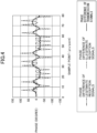
- FIG. 4 is a graph indicating the phase difference of the transmission signal, the phase difference of the legitimate reception signal, and the phase difference of the illegitimate reception signal.
- the horizontal axis represents a sample point (0.25 ⁇ s/point) at which sampling is performed, and the vertical axis represents the phase difference (the degrees).
- the phase difference of the transmission signal is an example of a first difference
- the phase difference of the legitimate reception signal and the phase difference of the illegitimate reception signal are examples of a second difference.
- the solid line indicates the phase difference of the transmission signal
- the dash-dot-dot line indicates the phase difference of the legitimate reception signal
- the dashed line indicates the phase difference of the illegitimate reception signal.
- the phase difference of the transmission signal is a difference (a phase difference) between a phase of the transmission signal and a phase sampled one cycle before in a sampling period.
- the sampling period is an example of a unit time, and such a phase difference of the transmission signal is a difference of the phase in the unit time (the first difference). That is, the phase difference of the transmission signal is a difference (a phase difference) between phases sampled in two consecutive sampling periods (two consecutive sample points) among the phases of the transmission signal repeatedly sampled in the distance measuring device 100A.
- the phase difference of the legitimate reception signal is a difference (a phase differences) between phases sampled in two consecutive sampling periods (two consecutive sample points) among the phases of the reception signal repeatedly sampled in the distance measuring device 100B.
- the phase difference of the illegitimate reception signal is a phase difference of the reception signal illegitimately generated by the illegitimate device impersonating the distance measuring device 100B based on the transmission signal of the distance measuring device 100A, and simulates a difference (a phase difference) between phases sampled in two consecutive sampling periods (two consecutive sample points) for the legitimate reception signal.
- the phase difference of the legitimate reception signal follows the phase difference of the transmission signal, and even if there is a delay with respect to the transmission signal, the delay is about one sample point to several sample points.
- the waveform of the phase difference of the legitimate reception signal is substantially the same as the waveform of the phase difference of the transmission signal.
- phase difference of the illegitimate reception signal changes when the phase difference of the transmission signal changes, but the phase itself changes sharply as indicated in FIG. 3 , and therefore the phase difference also changes sharply as indicated in FIG. 4 .
- the phase difference of the legitimate reception signal and the phase difference of the illegitimate reception signal are completely different in the manner of change.
- the wireless device 100R and the distance measuring device 100A determine whether it is the legitimate distance measuring device 100B or the illegitimate device based on such a difference in temporal change.
- FIG. 5 is a diagram illustrating an example of a data structure of the BLE (registered trademark) packet.
- the BLE packet includes a preamble, an access address, a protocol data unit, and a CRC from the head.
- the protocol data unit includes areas, such as a header, a payload, and the like.
- the phase acquiring unit 175 of the distance measuring device 100B may acquire the data representing the phase and write the acquired data in the payload of the BLE packet.
- the data representing the phase data obtained by setting a value in a high frequency section to 1 and setting a value in a low frequency section to 0 in frequency shift keying (FSK) modulation may be used.
- FSK frequency shift keying
- FIG. 6 is a graph for explaining a correlation between the phase difference of the transmission signal and the phase difference of the reception signal.
- the horizontal axis represents a difference between the sample points of the transmission signal and the reception signal
- the vertical axis represents a correlation value between the phase difference of the transmission signal and the phase difference of the reception signal.
- the difference between the sample points on the horizontal axis is the difference between the sample points at which the phases of the transmission signal and the reception signal are acquired
- the phase differences of the transmission signal and the reception signal is the phase differences obtained by subtracting, from the phase at each sample point, the phase at the sample point immediately before the sample point.
- the solid line indicates an example of the correlation between the phase difference of the transmission signal of the distance measuring device 100A and the phase difference of the reception signal of the legitimate distance measuring device 100B
- the dashed line indicates an example of the correlation between the phase difference of the transmission signal of the distance measuring device 100A and the phase difference of the reception signal of the illegitimate device.
- the correlation between the phase difference of the transmission signal of the distance measuring device 100A and the phase difference of the reception signal of the legitimate distance measuring device 100B has a maximum value close to 1 as indicated by the solid line.
- a correlation characteristic having such a large maximum value can be obtained by shifting the sample point, for example, within the range of ⁇ 10.
- the maximum value of the correlation can be obtained by shifting the sample point within the range of ⁇ 10. In order to obtain the maximum value of the correlation, it is only necessary to shift the sample point within a range in which the peak of the phase difference exists.
- the correlation between the phase difference of the transmission signal of the distance measuring device 100A and the phase difference of the reception signal of the illegitimate device has a low maximum value as indicated by the dashed line. This is because, as illustrated in FIG. 4 , the phase difference of the reception signal of the illegitimate device changes sharply, and the waveform of the phase difference of the reception signal is completely different from the waveform of the phase difference of the transmission signal.
- the phase difference is a phase difference of the reception signal of the legitimate distance measuring device 100B or a phase difference of the reception signal of the illegitimate device.
- Such determination may be performed by the determining unit 177 of the control device 170.
- the determining unit 177 may calculate the correlation as illustrated in FIG. 6 , determine that the device is legitimate when the maximum value of the correlation is greater than or equal to a threshold value, and determine that the device is illegitimate when the maximum value of the correlation is less than the threshold value.
- the threshold value may be set to a value from 0.7 to 0.8, for example.
- FIG. 7 is a flowchart illustrating a process performed by the control device 170 to determine whether the device is illegitimate.
- the process illustrated in FIG. 7 is a process for realizing a method for controlling the wireless device 100R.
- the main control unit 171 causes the setting unit 172 to set the frequency (the predetermined frequency) and the phase of the signal to be transmitted, transmits the transmission signal, and acquires the phase of the transmission signal and the phase of the reception signal (step S1) .
- the difference calculating unit 176 calculates the first difference of the phase of the predetermined-frequency transmission signal transmitted from the OM 130 to the distance measuring device 100B in the unit time and the second difference of the phase of the predetermined-frequency reception signal received by the other device based on the signal received by the ODM 140 in the unit time (step S2).
- the determining unit 177 calculates the correlation (step S3).
- the characteristic of the correlation having the maximum value may be obtained by shifting the sample point within the range of ⁇ 10, for example.
- the determining unit 177 determines whether the device is legitimate (step S4). It may be determined whether the device is legitimate by determining whether the maximum value of the correlation is greater than or equal to the threshold value.
- the determining unit 177 In response to determining that the device is legitimate (S4: YES), the determining unit 177 notifies the phase measuring unit 178 and the distance measuring unit 179 that the device is legitimate (step S5).
- step S5 a series of processing is ended (end), and the process is performed again from start. That is, the determining unit 177 continues the determination process.
- the phase measuring unit 178 and the distance measuring unit 179 measure the phase for the distance measuring and perform the distance measuring in response to being notified that the device is legitimate.
- the determining unit 177 stops the transmission process and the reception process of the OM 130 and the ODM 140 (step S6). This is to prevent illegitimate access to the vehicles 10 because a legitimate access right to the distance measuring device 100A is not owned.
- the determining unit 177 notifies the phase measuring unit 178 and the distance measuring unit 179 that the device is not legitimate (step S7).
- phase measuring unit 178 and the distance measuring unit 179 are notified that the device is not legitimate, the process is ended without measuring the phase for the distance measuring and performing the distance measuring.
- a high-level device an ECU configured to manage the vehicle 10 or the like
- the distance measuring device 100A and the wireless device 100R are notified that access has been made from the illegitimate device, and the doors of the vehicle 10 cannot be unlocked, the ignition switches cannot be switched on, and the like.
- the determining unit 177 stops the determination process (step S8). All the processing is stopped because the device is accessed by an illegitimate device. In this case, the process is stopped without returning to the start.
- the process may be recoverable when the signal of the legitimate device is received and the device is determined to be the legitimate device after the stop.
- the difference calculating unit 176 obtains the first difference of the phase of the transmission signal and calculates the second difference of the phase of the reception signal, and the determining unit 177 compares the first difference and the second difference to determine the legitimacy of the signal. Therefore, a case where the phase of the reception signal is sharply changed by the EDLC can be determined.
- the wireless device 100R that can detect a relay attack of changing the phase of the reception signal and impersonating a legitimate device, and a method for controlling the wireless device 100R can be provided.
- the determining unit 177 continues the determination process in response to determining that the device is legitimate, and stops the determination process in response to determining that the device is not legitimate.
- the vehicle 10 can be prevented from being accessed by an illegitimate device and being illegitimately used.
- the determining unit 177 stops the determination process and stops the transmission process and the reception process of the OM 130 and the ODM 140 in response to determining that the device is not legitimate, thereby preventing illegitimate access to the vehicle 10.
- an illegitimate device can be found based on the phase difference when an illegitimate operation of changing the phase of the reception signal sharply is performed as in the EDLC.
Landscapes
- Engineering & Computer Science (AREA)
- Signal Processing (AREA)
- Computer Networks & Wireless Communication (AREA)
- Radar, Positioning & Navigation (AREA)
- Physics & Mathematics (AREA)
- General Physics & Mathematics (AREA)
- Remote Sensing (AREA)
- Computer Security & Cryptography (AREA)
- Mechanical Engineering (AREA)
- Mobile Radio Communication Systems (AREA)
- Radar Systems Or Details Thereof (AREA)
- Lock And Its Accessories (AREA)
- Transceivers (AREA)
Abstract
Description
- The present disclosure relates to a wireless device and a method for controlling the wireless device.
- Conventionally, there is a method for relay attack resistant communication. In the method for the relay attack resistant communication, a master wireless device that transmits a synchronization signal to a slave wireless device is included, the synchronization signal includes timing information, and the timing information includes a common time reference and a time slot duration for coordinating master and slave communication time slots so that alternating TX and RX roll patterns are provided to the master and to the slave. The master analyzes slave packet data received from the slave to identify an overlap of transmissions from the master and slave packet data, which is a packet error, and in the case of the packet error, the communication from the master to the slave is interrupted to prevent a relay attack (for example, see Patent Document 1).
- Patent Document 1:
Japanese National Publication of International Patent Application No. 2019-533096 - In a conventional method for the relay attack resistant communication, the packet error is detected by using a common time reference and a time slot duration for coordinating the master and slave communication time slots. Therefore, for example, in a case where a master device serving as "master" changes a phase of a transmission signal to be transmitted to a slave device serving as "slave", if an illegitimate slave device receives a transmission signal and impersonates a legitimate slave device by changing a phase of the transmission signal, the illegitimate slave device cannot be detected. The relay attack method for changing the phase of the transmission signal and impersonating a legitimate slave device is called early detect late commitment (EDLC).
- Therefore, it is an object to provide a wireless device that can detect a relay attack of impersonating a legitimate device by changing a phase of a reception signal, and a method for controlling the wireless device.
- A wireless device according to the present disclosure includes a transmitter configured to transmit a signal to another device; a receiver configured to receive a signal from the another device; a difference calculating unit configured to obtain a first difference of a predetermined physical quantity, in a unit time, of a predetermined-frequency signal transmitted by the transmitter to the another device, and calculate a second difference of the predetermined physical quantity, in the unit time, of the predetermined-frequency signal received by the another device, based on the signal received by the receiver; and a determining unit configured to perform a determination process of comparing the first difference and the second difference to determine legitimacy of the signal received by the receiver.
- A wireless device that can detect a relay attack of impersonating a legitimate device by changing a phase of a reception signal, and a method for controlling the wireless device can be provided.
-
- [
FIG. 1] FIG. 1 is a diagram illustrating a vehicle and a smart key each implementing a distance measuring device including a wireless device according to an embodiment. - [
FIG. 2] FIG. 2 is a diagram illustrating the distance measuring device of the embodiment. - [
FIG. 3] FIG. 3 is a graph for explaining a phase of a transmission signal and a phase of an illegitimate reception signal. - [
FIG. 4] FIG. 4 is a graph indicating a phase difference of the transmission signal, a phase difference of a legitimate reception signal, and a phase difference of the illegitimate reception signal. - [
FIG. 5] FIG. 5 is a diagram illustrating an example of a data structure of a BLE packet. - [
FIG. 6] FIG. 6 is a graph for explaining a correlation between a phase difference of the transmission signal and a phase difference of the reception signal. - [
FIG. 7] FIG. 7 is a flowchart illustrating a process performed by a control device to determine whether a device is illegitimate. - In the following, an embodiment in which a wireless device and a method for controlling the wireless device of the present disclosure are applied will be described.
-
FIG. 1 is a diagram illustrating avehicle 10 and asmart key 20 in which distance measuringdevices distance measuring device 100A is implemented in a smart entry system mounted in thevehicle 10 and thedistance measuring device 100B is implemented in thesmart key 20 of thevehicle 10 will be described. The distance measuringdevices - At least either the distance measuring
device 100A of thevehicle 10 or thedistance measuring device 100B of thesmart key 20 measures a distance between thevehicle 10 and thesmart key 20, and locks of a door, a trunk, and the like of thevehicle 10 are unlocked when the distance measured by the distance measuringdevice - Here, as an example, it is assumed that the distance measuring
device 100A of thevehicle 10 performs distance measuring, and notifies thedistance measuring device 100B of thesmart key 20 of a result of the distance measuring. The distance measuringdevices devices distance measuring device 100. The distance measuringdevice 100B that does not perform distance measuring among thedistance measuring device 100A of thevehicle 10 and thedistance measuring device 100B of thesmart key 20 is an example of another device. It is noted that it is possible to handle thedistance measuring device 100A as a master device and thedistance measuring device 100B as a slave device, or conversely, to handle thedistance measuring device 100B as a master device and thedistance measuring device 100A as a slave device, but here, description will be given without such handling. -
FIG. 2 is a diagram illustrating thedistance measuring device 100A of the embodiment. As described above, the distance measuringdevice 100A of thevehicle 10 and thedistance measuring device 100B of thesmart key 20 have the same configuration. Here, the distance measuringdevice 100A that performs the distance measuring will be described. Additionally, thedistance measuring device 100A includes awireless device 100R of the embodiment. The components included in thewireless device 100R are denoted by areference symbol 100R in parentheses. - The
distance measuring device 100A includes anantenna 101, a power amplifier (PA) 110, a low noise amplifier (LNA) 120, an orthogonal modulator (OM) 130, an orthogonal demodulator (ODM) 140, a voltage controlled oscillator (VCO) 150, a phase locked loop (PLL) 155, acodec processor 160, and acontrol device 170. Thewireless device 100R includes components other than aphase measuring unit 178 and adistance measuring unit 179 of thecontrol device 170 among the components of thedistance measuring device 100A. Therefore, thereference symbol 100R is written in parentheses for the components other than thephase measuring unit 178 and thedistance measuring unit 179 of thecontrol device 170 among the components of thedistance measuring device 100A. - The
antenna 101 performs communication with theantenna 101 of thedistance measuring device 100Bsmart key 20. Theantenna 101 is connected to the PA 110 and the LNA 120. Here, a switch for switching the connection destination of theantenna 101 to either thePA 110 or the LNA 120 is omitted. - The PA 110 is provided between the
OM 130 and theantenna 101, and amplifies a modulated signal for transmission that is input from theOM 130 and outputs the amplified signal to theantenna 101. The PA 110 is an amplifier for transmission. - The LNA 120 is provided between the
antenna 101 and theODM 140, and amplifies a radio wave received by theantenna 101 with low noise and outputs the amplified radio wave to theODM 140. The LNA 120 is an amplifier for reception. - The OM 130 is an example of a transmitter, and modulates an I/Q signal input from the
codec processor 160 by using a high-frequency signal input from theVCO 150, and outputs the modulated signal to thePA 110 as a modulated signal for transmission. - The
ODM 140 is an example of a receiver, and demodulates a signal output from theLNA 120 by using a high-frequency signal input from theVCO 150 to obtain the I/Q signal, and outputs the I/Q signal to thecodec processor 160. The signal output from theLNA 120 is a signal received by thedistance measuring device 100A from thedistance measuring device 100B. - The
VCO 150 oscillates at the frequency set by thePLL 155. The VCO 150 can oscillate at multiple frequencies set by the PLL 155. - The
PLL 155 sets the frequency at which theVCO 150 oscillates. The PLL 155 can set multiple frequencies in the VCO 150. - The
codec processor 160 includes an analog to digital converter (ADC) and a digital to analog converter (DAC), and performs codec processing. Thecodec processor 160 performs detection of a BLE (registered trademark) packet, address determination processing, and the like. More specifically, thecodec processor 160 performs digital conversion (ADC processing) on the I/Q signal processed in theODM 140, and converts the I/Q signal into the packet information of BLE. Additionally, thecodec processor 160 generates the I/Q signal (divides an I signal and a Q signal) from a BLE packet (digital signal) input from thecontrol device 170, converts the I/Q signal into an analog signal by DAC processing, and outputs the analog signal to theOM 130 as the I/Q signal serving as a transmission signal. - In the following, a predetermined-frequency signal that is transmitted from the
OM 130 of thedistance measuring device 100A to thedistance measuring device 100B is referred to as a transmission signal. Additionally, a signal transmitted as the transmission signal by thedistance measuring device 100A and received by another device is referred to as a reception signal. - The
control device 170 includes amain control unit 171, asetting unit 172, a notifyingunit 173, aswitching unit 174, aphase acquiring unit 175, adifference calculating unit 176, a determiningunit 177, thephase measuring unit 178, thedistance measuring unit 179, and amemory 170M. Thememory 170M is an example of a storage unit. Thecontrol device 170 is implemented by a microcomputer including a central processing unit (CPU), a random access memory (RAM), a read only memory (ROM), an input/output interface, an internal bus, and the like. - The
main control unit 171, thesetting unit 172, the notifyingunit 173, theswitching unit 174, thephase acquiring unit 175, thedifference calculating unit 176, the determiningunit 177, thephase measuring unit 178, and thedistance measuring unit 179 indicate functions of a program executed by thecontrol device 170 as functional blocks. Additionally, thememory 170M functionally represents a memory of thecontrol device 170. - The
main control unit 171 is a processing unit that controls processing of thecontrol device 170, and performs processing other than processing performed by thesetting unit 172, the notifyingunit 173, theswitching unit 174, thephase acquiring unit 175, thedifference calculating unit 176, the determiningunit 177, thephase measuring unit 178, and thedistance measuring unit 179. - The
setting unit 172 sets the frequency (the predetermined frequency) and the phase of the signal to be transmitted from thedistance measuring device 100A to thedistance measuring device 100B. Additionally, thedistance measuring device 100B transmits, to thedistance measuring device 100A, a signal having a frequency the same as the frequency of the signal transmitted to thedistance measuring device 100A. Here, the same frequency of the signal transmitted by thedistance measuring devices distance measuring devices - The notifying
unit 173 notifies the notifyingunit 173 of thedistance measuring device 100B in thesmart key 20 of the result of the distance measuring. For the notification, a BLE packet communication having a frequency different from that of the communication for the distance measuring is used. In the notification, the result of the distance measuring and the like may be written in a payload of the BLE packet. - The
switching unit 174 switches between a transmission state in which theOM 130 transmits the signal and a reception state in which theODM 140 receives the signal. Theswitching unit 174 allows thePA 110 to amplify the signal in the transmission state and allows the LNA to amplify the signal in the reception state. Theswitching unit 174 provides a stabilization time for stabilizing the phase and the frequency when switching between the transmission state and the reception state. - The
phase acquiring unit 175 acquires, from thedistance measuring device 100B, the phase when thedistance measuring device 100B receives the predetermined-frequency transmission signal that is transmitted by thedistance measuring device 100A, as the reception signal. Thephase acquiring unit 175 acquires data representing the phase from thedistance measuring device 100B by the BLE packet communication having a frequency different from that of the communication for the distance measuring. The data representing the phase may be written in the payload of the BLE packet. Additionally, the data representing the phase may be measured by thephase measuring unit 178 of thedistance measuring device 100B and transmitted to thedistance measuring device 100A. - The
difference calculating unit 176 obtains a first difference of the phase of the predetermined-frequency transmission signal transmitted by theOM 130 to thedistance measuring device 100B, and calculates a second difference of the phase of the predetermined-frequency reception signal received by another device, using the data representing the phase acquired by thephase acquiring unit 175 based on the signal received by theODM 140. The phase is an example of a predetermined physical quantity. - Another device is either the
distance measuring device 100B or the illegitimate device. Thedistance measuring device 100B is a legitimate device having legitimate access authority to thedistance measuring device 100A. The illegitimate device is a device that impersonates thedistance measuring device 100B, which is the legitimate device, and is a device that does not have legitimate access authority to thedistance measuring device 100A. The first difference and the second difference are used when determining the legitimacy of the device that is a transmission source having transmitted the signal received by theODM 140. Methods for calculating the first difference and the second difference will be described later with reference toFIG. 3 andFIG. 4 . - The determining
unit 177 performs a determination process of comparing the first difference and the second difference calculated by thedifference calculating unit 176, to determine the legitimacy of the signal received by theODM 140. The determination of the legitimacy by the determiningunit 177 indicates that the determiningunit 177 determines the legitimacy of the device that is the transmission source having transmitted the signal received by theODM 140. More specifically, the determiningunit 177 determines whether the transmission source is thedistance measuring device 100B or the illegitimate device impersonating thedistance measuring device 100B. - The
phase measuring unit 178 measures the phase when thedistance measuring device 100A receives the predetermined-frequency signal from thedistance measuring device 100B. This phase is measured for distance measuring. Therefore, thephase measuring unit 178 is not included in the components of thewireless device 100R. - The
distance measuring unit 179 performs the distance measuring of the distance between thedistance measuring device 100A and thedistance measuring device 100B based on the phase of the transmission signal acquired by thephase acquiring unit 175, the phase measured by thephase measuring unit 178, and the number of waves of the transmission signal and the reception signal between thedistance measuring device 100A and thedistance measuring device 100B. - The
memory 170M stores programs, data, and the like that are necessary for themain control unit 171, thesetting unit 172, the notifyingunit 173, theswitching unit 174, thephase acquiring unit 175, thedifference calculating unit 176, the determiningunit 177, thephase measuring unit 178, and thedistance measuring unit 179 of thecontrol device 170 to perform the above-described processing. Thememory 170M stores data and the like in which the predetermined frequency and phases of the signals to be transmitted to each other between thedistance measuring devices -
FIG. 3 is a graph for explaining the phase of the transmission signal and the phase of the illegitimate reception signal. The illegitimate reception signal is a reception signal whose phase is falsified by the illegitimate device. InFIG. 3 , the horizontal axis represents a sample point (0.25 ps/point) at which sampling is performed, the vertical axis on the left side represents the phase (the degree), and the vertical axis on the right side represents a symbol value (0 or 1). The horizontal axis represents the sample point, and thus corresponds to a time axis. - In
FIG. 3 , the dash-dotted line indicates a symbol value (transmission symbol) of a BLE (registered trademark) packet (a digital signal) input from thecontrol device 170 to thecodec processor 160. Additionally, the solid line indicates the phase of the transmission signal, and the dashed line indicates the phase of the illegitimate reception signal. - As an example, when the symbol value of the BLE packet changes as illustrated in
FIG. 3 , the phase of the I/Q signal as the transmission signal generated based on the BLE packet changes as indicated by the solid line. Although not illustrated inFIG. 3 , the phase of the reception signal of the legitimatedistance measuring device 100B changes following the phase of the transmission signal indicated by the solid line, and therefore, has a waveform in which the reception signal is delayed by one sample point to several sample points with respect to the transmission signal. - The phase of the illegitimate reception signal indicated by the dashed line in
FIG. 3 represents an example of the phase of the illegitimate reception signal that can be generated by a relay attack method called EDLC, for example. The EDLC is a method for estimating a transmission symbol of a reception signal, generating a reception signal having a phase rise timing earlier than that of the reception signal based on the estimated transmission symbol, storing it in a payload of a BLE packet, and transmitting the reception signal to thedistance measuring device 100A. As described above, the EDLC attempts to perform a relay attack by falsifying the phase, causing thedistance measuring device 100A to incorrectly calculate the distance between the illegitimate device and thedistance measuring device 100A, and impersonating the legitimatedistance measuring device 100B. - The phase of the illegitimate reception signal generated by the EDLC changes sharply so as to follow the symbol value of the BLE packet, and consequently, the phase of the illegitimate reception signal has a pattern that also follows the phase of the transmission signal. If the phase changes sharply in this way, it is not detected as a bit abnormality in the conventional method for the relay attack resistant communication.
-
FIG. 4 is a graph indicating the phase difference of the transmission signal, the phase difference of the legitimate reception signal, and the phase difference of the illegitimate reception signal. The horizontal axis represents a sample point (0.25 µs/point) at which sampling is performed, and the vertical axis represents the phase difference (the degrees). The phase difference of the transmission signal is an example of a first difference, and the phase difference of the legitimate reception signal and the phase difference of the illegitimate reception signal are examples of a second difference. - In
FIG. 4 , the solid line indicates the phase difference of the transmission signal, the dash-dot-dot line indicates the phase difference of the legitimate reception signal, and the dashed line indicates the phase difference of the illegitimate reception signal. - The phase difference of the transmission signal is a difference (a phase difference) between a phase of the transmission signal and a phase sampled one cycle before in a sampling period. The sampling period is an example of a unit time, and such a phase difference of the transmission signal is a difference of the phase in the unit time (the first difference). That is, the phase difference of the transmission signal is a difference (a phase difference) between phases sampled in two consecutive sampling periods (two consecutive sample points) among the phases of the transmission signal repeatedly sampled in the
distance measuring device 100A. - Similarly, the phase difference of the legitimate reception signal is a difference (a phase differences) between phases sampled in two consecutive sampling periods (two consecutive sample points) among the phases of the reception signal repeatedly sampled in the
distance measuring device 100B. - Additionally, the phase difference of the illegitimate reception signal is a phase difference of the reception signal illegitimately generated by the illegitimate device impersonating the
distance measuring device 100B based on the transmission signal of thedistance measuring device 100A, and simulates a difference (a phase difference) between phases sampled in two consecutive sampling periods (two consecutive sample points) for the legitimate reception signal. - As illustrated in
FIG. 4 , the phase difference of the legitimate reception signal follows the phase difference of the transmission signal, and even if there is a delay with respect to the transmission signal, the delay is about one sample point to several sample points. The waveform of the phase difference of the legitimate reception signal is substantially the same as the waveform of the phase difference of the transmission signal. - In contrast, the phase difference of the illegitimate reception signal changes when the phase difference of the transmission signal changes, but the phase itself changes sharply as indicated in
FIG. 3 , and therefore the phase difference also changes sharply as indicated inFIG. 4 . - As described, the phase difference of the legitimate reception signal and the phase difference of the illegitimate reception signal are completely different in the manner of change. The
wireless device 100R and thedistance measuring device 100A according to the embodiment determine whether it is the legitimatedistance measuring device 100B or the illegitimate device based on such a difference in temporal change. -
FIG. 5 is a diagram illustrating an example of a data structure of the BLE (registered trademark) packet. The BLE packet includes a preamble, an access address, a protocol data unit, and a CRC from the head. The protocol data unit includes areas, such as a header, a payload, and the like. As an example, thephase acquiring unit 175 of thedistance measuring device 100B may acquire the data representing the phase and write the acquired data in the payload of the BLE packet. Here, as an example, as the data representing the phase, data obtained by setting a value in a high frequency section to 1 and setting a value in a low frequency section to 0 in frequency shift keying (FSK) modulation may be used. -
FIG. 6 is a graph for explaining a correlation between the phase difference of the transmission signal and the phase difference of the reception signal. InFIG. 6 , the horizontal axis represents a difference between the sample points of the transmission signal and the reception signal, and the vertical axis represents a correlation value between the phase difference of the transmission signal and the phase difference of the reception signal. The difference between the sample points on the horizontal axis is the difference between the sample points at which the phases of the transmission signal and the reception signal are acquired, and the phase differences of the transmission signal and the reception signal is the phase differences obtained by subtracting, from the phase at each sample point, the phase at the sample point immediately before the sample point. - In
FIG. 6 , the solid line indicates an example of the correlation between the phase difference of the transmission signal of thedistance measuring device 100A and the phase difference of the reception signal of the legitimatedistance measuring device 100B, and the dashed line indicates an example of the correlation between the phase difference of the transmission signal of thedistance measuring device 100A and the phase difference of the reception signal of the illegitimate device. - The correlation between the phase difference of the transmission signal of the
distance measuring device 100A and the phase difference of the reception signal of the legitimatedistance measuring device 100B has a maximum value close to 1 as indicated by the solid line. As described with respect toFIG. 4 , because the waveform of the phase difference of the legitimate reception signal is substantially the same as the waveform of the phase difference of the transmission signal, a correlation characteristic having such a large maximum value can be obtained by shifting the sample point, for example, within the range of ±10. Here, in this case, because the peak of the phase difference exists within the range of ±10 of the sample point, the maximum value of the correlation can be obtained by shifting the sample point within the range of ±10. In order to obtain the maximum value of the correlation, it is only necessary to shift the sample point within a range in which the peak of the phase difference exists. - With respect to the above, the correlation between the phase difference of the transmission signal of the
distance measuring device 100A and the phase difference of the reception signal of the illegitimate device has a low maximum value as indicated by the dashed line. This is because, as illustrated inFIG. 4 , the phase difference of the reception signal of the illegitimate device changes sharply, and the waveform of the phase difference of the reception signal is completely different from the waveform of the phase difference of the transmission signal. - Therefore, for example, by performing determination on the maximum value of the correlation by using an appropriate threshold, it can be determined whether the phase difference is a phase difference of the reception signal of the legitimate
distance measuring device 100B or a phase difference of the reception signal of the illegitimate device. Such determination may be performed by the determiningunit 177 of thecontrol device 170. The determiningunit 177 may calculate the correlation as illustrated inFIG. 6 , determine that the device is legitimate when the maximum value of the correlation is greater than or equal to a threshold value, and determine that the device is illegitimate when the maximum value of the correlation is less than the threshold value. Here, in the example ofFIG. 6 , the threshold value may be set to a value from 0.7 to 0.8, for example. -
FIG. 7 is a flowchart illustrating a process performed by thecontrol device 170 to determine whether the device is illegitimate. The process illustrated inFIG. 7 is a process for realizing a method for controlling thewireless device 100R. - First, when the process starts, the
main control unit 171 causes thesetting unit 172 to set the frequency (the predetermined frequency) and the phase of the signal to be transmitted, transmits the transmission signal, and acquires the phase of the transmission signal and the phase of the reception signal (step S1) . - The
difference calculating unit 176 calculates the first difference of the phase of the predetermined-frequency transmission signal transmitted from theOM 130 to thedistance measuring device 100B in the unit time and the second difference of the phase of the predetermined-frequency reception signal received by the other device based on the signal received by theODM 140 in the unit time (step S2). - The determining
unit 177 calculates the correlation (step S3). In step S3, as illustrated inFIG. 6 , the characteristic of the correlation having the maximum value may be obtained by shifting the sample point within the range of ±10, for example. - The determining
unit 177 determines whether the device is legitimate (step S4). It may be determined whether the device is legitimate by determining whether the maximum value of the correlation is greater than or equal to the threshold value. - In response to determining that the device is legitimate (S4: YES), the determining
unit 177 notifies thephase measuring unit 178 and thedistance measuring unit 179 that the device is legitimate (step S5). When the processing of step S5 is ended, a series of processing is ended (end), and the process is performed again from start. That is, the determiningunit 177 continues the determination process. - The
phase measuring unit 178 and thedistance measuring unit 179 measure the phase for the distance measuring and perform the distance measuring in response to being notified that the device is legitimate. - In response to determining that the device is not legitimate in step S4 (S4: NO), the determining
unit 177 stops the transmission process and the reception process of theOM 130 and the ODM 140 (step S6). This is to prevent illegitimate access to thevehicles 10 because a legitimate access right to thedistance measuring device 100A is not owned. - Next, the determining
unit 177 notifies thephase measuring unit 178 and thedistance measuring unit 179 that the device is not legitimate (step S7). - When the
phase measuring unit 178 and thedistance measuring unit 179 are notified that the device is not legitimate, the process is ended without measuring the phase for the distance measuring and performing the distance measuring. In this case, a high-level device (an ECU configured to manage thevehicle 10 or the like) of thedistance measuring device 100A and thewireless device 100R are notified that access has been made from the illegitimate device, and the doors of thevehicle 10 cannot be unlocked, the ignition switches cannot be switched on, and the like. - Next, the determining
unit 177 stops the determination process (step S8). All the processing is stopped because the device is accessed by an illegitimate device. In this case, the process is stopped without returning to the start. Here, for example, the process may be recoverable when the signal of the legitimate device is received and the device is determined to be the legitimate device after the stop. - As described above, the
difference calculating unit 176 obtains the first difference of the phase of the transmission signal and calculates the second difference of the phase of the reception signal, and the determiningunit 177 compares the first difference and the second difference to determine the legitimacy of the signal. Therefore, a case where the phase of the reception signal is sharply changed by the EDLC can be determined. - Therefore, the
wireless device 100R that can detect a relay attack of changing the phase of the reception signal and impersonating a legitimate device, and a method for controlling thewireless device 100R can be provided. - Additionally, the determining
unit 177 continues the determination process in response to determining that the device is legitimate, and stops the determination process in response to determining that the device is not legitimate. Thevehicle 10 can be prevented from being accessed by an illegitimate device and being illegitimately used. - Additionally, the determining
unit 177 stops the determination process and stops the transmission process and the reception process of theOM 130 and theODM 140 in response to determining that the device is not legitimate, thereby preventing illegitimate access to thevehicle 10. - Additionally, because the phase is used as the predetermined physical quantity of the transmission signal and the reception signal, an illegitimate device can be found based on the phase difference when an illegitimate operation of changing the phase of the reception signal sharply is performed as in the EDLC.
- Although the wireless device and the method for controlling the wireless device according to the exemplary embodiments of the present disclosure have been described above, the present disclosure is not limited to the specifically disclosed embodiments, and various modifications and changes can be made without departing from the scope of the claims.
- This international application claims priority to
Japanese Patent Application No. 2021-193984 filed on November 30, 2021 -
- 10 vehicle
- 20 smart key
- 100A and 100B distance measuring device
- 100R radio device
- 110 PA
- 120 LNA
- 130 OM (an example of a transmitter)
- 140 ODM (an example of a receiver)
- 150 VCO
- 155 PLL
- 160 codec processor
- 170 control device
- 171 main control unit
- 172 setting unit
- 173 notifying unit
- 174 switching unit
- 175 phase acquiring unit
- 176 difference calculating unit
- 177 determining unit
- 178 phase measuring unit
- 179 distance measuring unit
- 170M memory
Claims (5)
- A wireless device comprising:a transmitter configured to transmit a signal to another device;a receiver configured to receive a signal from the another device;a difference calculating unit configured to obtain a first difference of a predetermined physical quantity, in a unit time, of a predetermined-frequency signal transmitted by the transmitter to the another device, and calculate a second difference of the predetermined physical quantity, in the unit time, of the predetermined-frequency signal received by the another device, based on the signal received by the receiver; anda determining unit configured to perform a determination process of comparing the first difference and the second difference to determine legitimacy of the signal received by the receiver.
- The wireless device as claimed in claim 1, wherein the determining unit continues the determination process in response to determining that the signal received by the receiver is legitimate, and stops the determination process in response to determining that the signal received by the receiver is not legitimate.
- The wireless device as claimed in claim 2, wherein the determining unit stops the determination process in response to determining that the signal received by the receiver is not legitimate, and stops a transmission process and a reception process of the transmitter and the receiver.
- The wireless device as claimed in any one of claims 1 to 3, wherein the predetermined physical quantity is a phase of the signal.
- A method for controlling a wireless device includinga transmitter configured to transmit a signal to another device,a receiver configured to receive a signal from the another device, anda difference calculating unit configured to obtain a first difference of a predetermined physical quantity, in a unit time, of a predetermined-frequency signal transmitted by the transmitter to the another device, and calculate a second difference of the predetermined physical quantity, in the unit time, of the predetermined-frequency signal received by the another device, based on the signal received by the receiver,the method comprising comparing the first difference and the second difference to determine legitimacy of the signal received by the receiver.
Applications Claiming Priority (2)
| Application Number | Priority Date | Filing Date | Title |
|---|---|---|---|
| JP2021193984 | 2021-11-30 | ||
| PCT/JP2022/038184 WO2023100488A1 (en) | 2021-11-30 | 2022-10-13 | Wireless apparatus and method for controlling wireless apparatus |
Publications (2)
| Publication Number | Publication Date |
|---|---|
| EP4442941A1 true EP4442941A1 (en) | 2024-10-09 |
| EP4442941A4 EP4442941A4 (en) | 2025-07-30 |
Family
ID=86611821
Family Applications (1)
| Application Number | Title | Priority Date | Filing Date |
|---|---|---|---|
| EP22900922.0A Pending EP4442941A4 (en) | 2021-11-30 | 2022-10-13 | Wireless apparatus and method for controlling wireless apparatus |
Country Status (5)
| Country | Link |
|---|---|
| US (1) | US20240272291A1 (en) |
| EP (1) | EP4442941A4 (en) |
| JP (1) | JP7574513B2 (en) |
| CN (1) | CN118285063A (en) |
| WO (1) | WO2023100488A1 (en) |
Families Citing this family (1)
| Publication number | Priority date | Publication date | Assignee | Title |
|---|---|---|---|---|
| WO2023084986A1 (en) * | 2021-11-10 | 2023-05-19 | アルプスアルパイン株式会社 | Communication device, distance measuring device, and authentication method in communication device |
Family Cites Families (9)
| Publication number | Priority date | Publication date | Assignee | Title |
|---|---|---|---|---|
| US10234564B2 (en) * | 2013-08-14 | 2019-03-19 | Hemisphere Gnss Inc. | System and method for determining the direction of a false GNSS satellite signal transmitter |
| KR101716244B1 (en) * | 2016-01-04 | 2017-03-15 | 현대자동차주식회사 | Smart key and controlling method for the same |
| US10897477B2 (en) | 2016-07-01 | 2021-01-19 | Texas Instruments Incorporated | Relay-attack resistant communications |
| US11585943B2 (en) * | 2016-12-19 | 2023-02-21 | Magellan Systems Japan, Inc. | Detection and elimination of GNSS spoofing signals with PVT solution estimation |
| JP7142728B2 (en) | 2018-06-14 | 2022-09-27 | フラウンホーファー-ゲゼルシャフト・ツール・フェルデルング・デル・アンゲヴァンテン・フォルシュング・アインゲトラーゲネル・フェライン | METHOD FOR DETERMINING RELAY ATTACK, RELAY ATTACK DETECTION DEVICE AND COMPUTER PROGRAM |
| US10984615B2 (en) | 2018-10-12 | 2021-04-20 | Denso International America, Inc. | Passive entry/passive start access systems with tone exchange sniffing |
| JP7199391B2 (en) * | 2020-02-28 | 2023-01-05 | 株式会社東芝 | rangefinder |
| JP7424160B2 (en) * | 2020-03-26 | 2024-01-30 | 株式会社デンソー | security system |
| JP2021193984A (en) | 2020-06-12 | 2021-12-27 | ファーマーズサポート株式会社 | System for coping with bird and beast damage/insect damage to domestic animals |
-
2022
- 2022-10-13 WO PCT/JP2022/038184 patent/WO2023100488A1/en not_active Ceased
- 2022-10-13 CN CN202280076665.3A patent/CN118285063A/en active Pending
- 2022-10-13 EP EP22900922.0A patent/EP4442941A4/en active Pending
- 2022-10-13 JP JP2023564775A patent/JP7574513B2/en active Active
-
2024
- 2024-04-26 US US18/647,369 patent/US20240272291A1/en active Pending
Also Published As
| Publication number | Publication date |
|---|---|
| WO2023100488A1 (en) | 2023-06-08 |
| JP7574513B2 (en) | 2024-10-29 |
| CN118285063A (en) | 2024-07-02 |
| JPWO2023100488A1 (en) | 2023-06-08 |
| EP4442941A4 (en) | 2025-07-30 |
| US20240272291A1 (en) | 2024-08-15 |
Similar Documents
| Publication | Publication Date | Title |
|---|---|---|
| US11422250B2 (en) | Method and technique of power-efficient two-way phase based distance estimation using packet synchronized data capture | |
| US10543808B2 (en) | Passive remote keyless entry system with level-based anti-theft feature | |
| US9479952B2 (en) | Circuit, system and method for communication between two nodes of a radio network | |
| CN119906999A (en) | Electronic device for performing ranging by using ultra-wideband in wireless communication system and method for operating the electronic device | |
| KR101040315B1 (en) | Target detection device adapting to clutter environment | |
| WO2013074690A1 (en) | System and method for detecting chirping radar pulses | |
| US20070223525A1 (en) | Transmission of packets in a csma wireless network | |
| CN108512792B (en) | Device for radio apparatus | |
| US8295323B2 (en) | Synchronization for frequency hopping (FH) communication | |
| US11774577B2 (en) | Combined phase and time-of-flight measurement | |
| US20240272291A1 (en) | Wireless device and method for controlling wireless device | |
| KR102772962B1 (en) | Electronic device and method for performing ranging through uwb in wireless communication system | |
| US20180263001A1 (en) | Method of operating a receiver to process a preamble of a data packet, and to a receiver operating in accordance with the method | |
| US11632370B2 (en) | Communication device and system | |
| US20200264297A1 (en) | Secure Ranging | |
| JPH04222130A (en) | Interference detection circuit | |
| US9240816B2 (en) | Timing synchronization system and method of super regenerative receiver based on ultra low power communication | |
| US20210160001A1 (en) | Tampering detection in phase based ranging | |
| KR20250028410A (en) | Radar sensor device and method for operating the radar sensor device | |
| JP2011130231A (en) | Device and method for setting parameter | |
| JP7730997B2 (en) | distance measuring device | |
| JP6532976B2 (en) | Signal transmitting / receiving apparatus and method for detecting synchronization point in signal | |
| US20260059317A1 (en) | Attack detection at low sampling rate in round-trip timing estimation | |
| Daita et al. | An improved clear channel assessment technique for interference mitigation in FMCW radars | |
| US12425862B2 (en) | Attack detection in round-trip timing estimation |
Legal Events
| Date | Code | Title | Description |
|---|---|---|---|
| STAA | Information on the status of an ep patent application or granted ep patent |
Free format text: STATUS: THE INTERNATIONAL PUBLICATION HAS BEEN MADE |
|
| PUAI | Public reference made under article 153(3) epc to a published international application that has entered the european phase |
Free format text: ORIGINAL CODE: 0009012 |
|
| STAA | Information on the status of an ep patent application or granted ep patent |
Free format text: STATUS: REQUEST FOR EXAMINATION WAS MADE |
|
| 17P | Request for examination filed |
Effective date: 20240425 |
|
| AK | Designated contracting states |
Kind code of ref document: A1 Designated state(s): AL AT BE BG CH CY CZ DE DK EE ES FI FR GB GR HR HU IE IS IT LI LT LU LV MC ME MK MT NL NO PL PT RO RS SE SI SK SM TR |
|
| DAV | Request for validation of the european patent (deleted) | ||
| DAX | Request for extension of the european patent (deleted) | ||
| A4 | Supplementary search report drawn up and despatched |
Effective date: 20250702 |
|
| RIC1 | Information provided on ipc code assigned before grant |
Ipc: E05B 49/00 20060101AFI20250626BHEP Ipc: B60R 25/01 20130101ALI20250626BHEP Ipc: B60R 25/24 20130101ALI20250626BHEP Ipc: H04B 1/3822 20150101ALI20250626BHEP Ipc: H04B 1/59 20060101ALI20250626BHEP Ipc: H04W 12/122 20210101ALI20250626BHEP Ipc: H04W 12/63 20210101ALI20250626BHEP Ipc: G01S 11/02 20100101ALI20250626BHEP Ipc: G01S 5/02 20100101ALI20250626BHEP |
|
| STAA | Information on the status of an ep patent application or granted ep patent |
Free format text: STATUS: EXAMINATION IS IN PROGRESS |
|
| 17Q | First examination report despatched |
Effective date: 20251119 |
|
| GRAP | Despatch of communication of intention to grant a patent |
Free format text: ORIGINAL CODE: EPIDOSNIGR1 |
|
| STAA | Information on the status of an ep patent application or granted ep patent |
Free format text: STATUS: GRANT OF PATENT IS INTENDED |
|
| INTG | Intention to grant announced |
Effective date: 20260324 |