EP4442924A1 - A flashing assembly for use between two roof windows mounted in an inclined roof structure, a group of roof windows mounted using such a flashing assembly, and a method for mounting a flashing assembly between two roof windows - Google Patents
A flashing assembly for use between two roof windows mounted in an inclined roof structure, a group of roof windows mounted using such a flashing assembly, and a method for mounting a flashing assembly between two roof windows Download PDFInfo
- Publication number
- EP4442924A1 EP4442924A1 EP24168726.8A EP24168726A EP4442924A1 EP 4442924 A1 EP4442924 A1 EP 4442924A1 EP 24168726 A EP24168726 A EP 24168726A EP 4442924 A1 EP4442924 A1 EP 4442924A1
- Authority
- EP
- European Patent Office
- Prior art keywords
- flashing
- section
- roof
- flashing element
- frame
- Prior art date
- Legal status (The legal status is an assumption and is not a legal conclusion. Google has not performed a legal analysis and makes no representation as to the accuracy of the status listed.)
- Pending
Links
- 238000000034 method Methods 0.000 title claims abstract description 28
- 238000003780 insertion Methods 0.000 claims description 7
- 230000037431 insertion Effects 0.000 claims description 7
- 238000005452 bending Methods 0.000 claims description 6
- 229910052751 metal Inorganic materials 0.000 claims description 6
- 239000002184 metal Substances 0.000 claims description 6
- RYGMFSIKBFXOCR-UHFFFAOYSA-N Copper Chemical compound [Cu] RYGMFSIKBFXOCR-UHFFFAOYSA-N 0.000 claims description 3
- 239000004411 aluminium Substances 0.000 claims description 3
- 229910052782 aluminium Inorganic materials 0.000 claims description 3
- XAGFODPZIPBFFR-UHFFFAOYSA-N aluminium Chemical compound [Al] XAGFODPZIPBFFR-UHFFFAOYSA-N 0.000 claims description 3
- 229910052802 copper Inorganic materials 0.000 claims description 3
- 239000010949 copper Substances 0.000 claims description 3
- 238000010348 incorporation Methods 0.000 description 3
- XLYOFNOQVPJJNP-UHFFFAOYSA-N water Substances O XLYOFNOQVPJJNP-UHFFFAOYSA-N 0.000 description 3
- 230000000712 assembly Effects 0.000 description 2
- 238000000429 assembly Methods 0.000 description 2
- 238000010276 construction Methods 0.000 description 2
- 238000009434 installation Methods 0.000 description 2
- 239000011810 insulating material Substances 0.000 description 1
- 238000009413 insulation Methods 0.000 description 1
- 239000004922 lacquer Substances 0.000 description 1
- 239000000463 material Substances 0.000 description 1
- 239000011159 matrix material Substances 0.000 description 1
- 239000003973 paint Substances 0.000 description 1
- 230000035515 penetration Effects 0.000 description 1
- 239000003566 sealing material Substances 0.000 description 1
- 238000000926 separation method Methods 0.000 description 1
- 238000004078 waterproofing Methods 0.000 description 1
Images






Classifications
-
- E—FIXED CONSTRUCTIONS
- E04—BUILDING
- E04D—ROOF COVERINGS; SKY-LIGHTS; GUTTERS; ROOF-WORKING TOOLS
- E04D13/00—Special arrangements or devices in connection with roof coverings; Protection against birds; Roof drainage ; Sky-lights
- E04D13/14—Junctions of roof sheathings to chimneys or other parts extending above the roof
- E04D13/147—Junctions of roof sheathings to chimneys or other parts extending above the roof specially adapted for inclined roofs
- E04D13/1473—Junctions of roof sheathings to chimneys or other parts extending above the roof specially adapted for inclined roofs specially adapted to the cross-section of the parts extending above the roof
- E04D13/1475—Junctions of roof sheathings to chimneys or other parts extending above the roof specially adapted for inclined roofs specially adapted to the cross-section of the parts extending above the roof wherein the parts extending above the roof have a generally rectangular cross-section
-
- E—FIXED CONSTRUCTIONS
- E04—BUILDING
- E04D—ROOF COVERINGS; SKY-LIGHTS; GUTTERS; ROOF-WORKING TOOLS
- E04D13/00—Special arrangements or devices in connection with roof coverings; Protection against birds; Roof drainage ; Sky-lights
- E04D13/14—Junctions of roof sheathings to chimneys or other parts extending above the roof
- E04D13/147—Junctions of roof sheathings to chimneys or other parts extending above the roof specially adapted for inclined roofs
-
- E—FIXED CONSTRUCTIONS
- E04—BUILDING
- E04D—ROOF COVERINGS; SKY-LIGHTS; GUTTERS; ROOF-WORKING TOOLS
- E04D13/00—Special arrangements or devices in connection with roof coverings; Protection against birds; Roof drainage ; Sky-lights
- E04D13/03—Sky-lights; Domes; Ventilating sky-lights
- E04D13/0305—Supports or connecting means for sky-lights of flat or domed shape
- E04D13/031—Supports or connecting means for sky-lights of flat or domed shape characterised by a frame for connection to an inclined roof
Definitions
- the present invention relates to a flashing assembly for use between two roof windows, which are mounted side by side in an inclined roof structure and which each comprises a frame and a pane element, said flashing assembly comprising a first flashing element configured for extending along a frame member of the frame of a first roof window and a second flashing element configured for extending along a frame member of the frame of a second roof window, each flashing element comprising a first section and a second section, said first section extending along a width axis of the flashing element, being configured for extending between the first roof window and the second roof window, and having an interior side configured for facing the roof structure, and said second section extending in an exterior direction along a height axis of the flashing element and having an interior side configured for facing the frame of one of the roof windows, said second section having a first edge at the first section and a second edge located at a distance from the first section measured along the height axis.
- the invention further relates to a group of roof windows mounted using such a flash
- a flashing assembly comprising a plurality of flashing elements each extending over the roof structure and up along outer sides of the frames of the roof windows, thus covering any gaps between the roof structure and roof windows, is used. While the flashing elements used along outer sides of the roof windows facing the roof structure may be of a fairly simple construction, the flashing elements used along outer sides facing another roof window need to fit into the space available between the roof windows and a tight fit between them must be ensured to prevent that water penetration.
- DK154099 this was achieved by the first sections of the flashing elements being provided with flanges projecting in an exterior direction away from the interior side of the first sections and by arranging a cover member having flanges projecting in an opposite interior direction, so that it rode on the flanges of the flashing elements.
- An intermediate member was used to keep the flashing element from moving towards each other, once the flashing assembly had been mounted. While this flashing assembly worked well with respect to water proofing, the cover member takes up space in the gutter formed between the two roof windows, and the width of the flashing assembly needs to match the distance between the roof windows.
- a flashing assembly which is able to compensate for variations in the distance between the roof windows, is known from WO03/074812A1 .
- the first sections of the two flashing elements are interconnected in a manner allowing different mutual positions of the flashing elements along the width axis. If only a small adjustment of the mutual positioning is necessary, for example to compensate for imprecision in the mounting of the roof windows, the first sections are interconnected for example by bent edges of the first sections hooking into each other and allowing a telescopic movement.
- the first sections are provided with profiling, such as hollow longitudinal ribs fitting over each other, allowing the first sections to fit over each other in at least two different ways.
- the flashing elements have at least two predefined mutual positions, giving the flashing assembly at least two different configurations suitable for use when the two roof windows are mounted either close to each other or further apart, depending for example on the width of rafters of the roof structure. It, however, remains a problem that each of the flashing assemblies disclosed in WO03/074812A1 can either only be used for a limited number of predefined mutual distances between the roof windows or within a limited distance interval.
- this and further objects are achieved with a flashing assembly of the kind mentioned in the introduction which is furthermore characterised in that the first section of the first flashing element comprises two legs extending along the width axis and being located at a distance from each other measured along the height axis thereby forming a pocket between them, and that the first section of the second flashing element fits into the pocket of the first flashing element.
- the minimum width of the interval is defined by the width of the first section of the second flashing element and the depth of pocket and reached at full insertion into the pocket.
- the maximum width of the interval is defined by the sum of the widths of the first sections, minus an overlap needed to provide water tightness.
- the bottom of the gutter formed by the flashing assembly will be substantially flat, which is not only an aesthetical advantage but also results in good draining properties.
- a method for mounting a flashing assembly between two roof windows which are mounted side by side in an inclined roof structure and which each comprises a frame and a pane element, said method comprising:
- any reference to the frame of roof window is not to be understood in the strictly limited literal sense of the term frame, but that it may include insulating material arranged on or around the frame and/or an underroof collar or other items used for the installation of the roof window in the roof structure.
- One way of ensuring that a sufficient overlap between the first sections is maintained at all times is that the one of the two legs of the first section of the first flashing element located furthest from the second edge of the second section of the first flashing element has a flange projecting along the height axis in an exterior direction away from the interior side of the first section toward the other of the two legs, and that the first section of the second flashing element has a flange projecting along the height axis in an interior direction.
- the leg of the first flashing element located or extending furthest from the second edge of the second section of the first flashing element will be the one located closest to the roof structure and hence lowermost in the mounted state, and in the following it will therefore also be referred to as the lowermost leg.
- the flanges of the flashing elements each extends at an angle of more than 90 degrees in relation to the width axis so that they project back towards the respective second sections of the flashing elements. This may ease insertion of the second flashing element into the pocket of the first flashing element and/or allow the flanges to hook into each other thereby contributing to preventing unintended separation of the two flashing elements. Providing the flange on the first flashing element with an angle of more than 90 degrees may also contribute to preventing that any water reaching onto the lowermost leg of the first flashing element overflows and penetrates into the roof structure.
- flashing elements are typically made from sheet metal, such as aluminium or copper.
- the flashing elements including any flanges, may then be made by bending as will be described in more detail below with reference to the drawing.
- the flashing elements being made from sheet metal does not necessarily means that they consist only of sheet metal. Paint or lacquer may be applied to protect the surfaces of the flashing elements and/or to give them a desired colour or other surface properties.
- sealing material may be applied to ensure a tight connection with other members of the flashing assembly, with the roof windows, and/or with the roof structure.
- Flanges made by bending of sheet metal may be bent back during insertion of the first section of the second flashing element into the pocket of the first flashing element as they come into contact with each other and will then snap back when they have passed each other. It is also possible to make one flange softer than the other, so that one gives way for the other.
- the flange on the second flashing element may alternatively or additionally have a height along the height axis, which is larger than the distance between the two legs of the first flashing element. In that case the flange on the second flashing element will press against both of the two legs when inserted in the pocket, thus providing a frictional resistance, which will hinder unintentional movement of the flashing elements in relation to each other.
- the minimum overlap between the first sections is 20 mm or more.
- the first and second flashing elements When mounting the flashing assembly, the first and second flashing elements may be interconnected before being arranged at the roof windows. The first section of the second flashing element may then initially be fully inserted into the pocket of the first flashing element and when the first sections are in contact with the roof structure, the two flashing elements are pulled away from each other until the second sections of both flashing elements have come into contact with the frames of the roof windows.
- the flashing assembly is not supplied in a preassembled state, it may be advantageous that the first flashing element is mounted before the second flashing element. This allows that first flashing element to be arranged in tight contact with the frame of the first roof window, before mounting the second flashing element.
- the flashing elements are top flashing elements configured for extending along top frame member of the roof windows, bottom flashing elements configured for extending along bottom frame member of the roof windows, or gutter flashing elements configured for use between roof windows arranged above each other.
- Gutter flashing elements are for example used in an array of roof windows, where roof windows are arranged both side by side and above each other, such as in a two-by-two configuration. Such a configuration will require two top flashing elements, two gutter flashing elements, and two bottom flashing elements, four side flashing elements forming two flashing assemblies as described above and four separate side flashing elements.
- Top flashing elements and bottom flashing elements are intended to extend along top frame members and bottom frame members of roof windows, i.e. along the frame members extending perpendicular to the inclination of the roof structure and being above and below the pane element as seen in the direction of inclination.
- Side flashing elements are the flashing elements extending between the top and bottom flashing elements in the direction of inclination or between a gutter flashing element and a top or bottom flashing element.
- the first section of the second flashing element may be inserted fully into the pocket of the first flashing element, and the second flashing element may then it subsequently pulled back until the second section of the second flashing element comes into contact with the frame of the second roof window. This may contribute to facilitating a proper contact between the flashing element and the frames of the roof windows.
- the first section of the second flashing element may be bending during the insertion into the pocket. This is particularly considered advantageous when the flashing elements are top, bottom or gutter flashing elements, having a relatively large extend or extension along the width axes, as it allows the second flashing element to be swung into place as will be described in further detail below with reference to the drawing.
- An additional advantage with the inventive flashing assembly in some embodiments is that the flashing assembly can be mounted sideways. In turn, this does not require a lot of space above/below roof windows, which is a considerable improvement when roof windows are mounted above each other.
- spacings between neighbouring roof windows ranging between at least 100 and 130 mm may be accommodated.
- a feature described in relation to one of the aspects may also be incorporated in the other aspect, and the advantage of the feature is applicable to all aspects in which it is incorporated.
- a prior art flashing assembly 1 for use with two roof windows mounted adjacent to each other side by side in a sloped roof structure 3 is shown.
- the prior art figure has been adapted by the incorporation of reference numerals corresponding to embodiments of the present invention.
- the roof windows are not of importance, they are here represented only by two frames 2, each comprising a top frame member 21 and a bottom frame member 22 both extending horizontally in the mounted state and two side frame members 23, 24 extending in a slope direction of the roof structure in the mounted state.
- the roof structure 3 is represented only by a single rafter and a few laths and the slope direction is indicated by the arrow D.
- a width direction W and a height direction H see Fig. 5 .
- the flashing assembly 1 comprises two top flashing elements 11 each configured for extending along a top frame member 21, two bottom flashing elements 12 each configured for extending along a bottom frame member 22, two side flashing elements 13, 14 each configured for extending along a side frame member 23, 24, and a middle gutter flashing element 15 configured for extending between the two roof windows.
- Common to all flashing elements is that they comprise an outer portion 111, 121, 131, 141, 151 configured for extending substantially in plane with the roof structure and at least one inner portion 112, 122, 132, 142, 152 configured for extending up along a frame member of a roof window.
- the top flashing elements 11 and the bottom flashing elements 12 are provided with corner sections, 113, 114, 123, 124 configured for establishing an overlap with the side flashing elements 13, 14 and the middle gutter flashing element 15, and cover members 16, 17 are provided for interconnecting the corner sections 114 of the top flashing elements above the middle gutter flashing element.
- the flashing assembly 1 is configured for use with roof windows mounted deep in a roof structure, and the side flashing elements 13, 14 are configured for use at a left-hand side frame member 23 and at a right-hand side flashing element 14 of a roof window, respectively.
- a corresponding flashing assembly for four roof window mounted in a two-by-two configuration is shown. It includes two middle gutter flashing elements 15 corresponding to the one in Fig. 1 and extending between the two columns of roof windows, and two drainage gutter elements 18 extending horizontally between the two rows of roof windows.
- Fig. 3 shows a sketch of general engagement means between two elements making use of a separate cover member.
- Fig. 4 which shows the principles of the engagement between two flashing elements
- the flashing assembly 1 is intended for use between two roof windows 2, which are mounted side by side in an inclined roof structure 3 and which each comprises a frame and a pane element.
- Fig. 5 including the indication of the height direction H, the width direction W and the slope direction D. All directional axes are to be referenced to such directions.
- the flashing assembly 1 comprises a first flashing element generally designated 7 and configured for extending along a frame member of the frame of a first roof window and a second flashing element generally designated 8 configured for extending along a frame member of the frame of a second roof window.
- Each flashing element 7, 8 comprises a first section 71, 81 and a second section 72, 82.
- the first section 71, 81 extends along a width axis of the flashing element 7, 8 in the mounted state of the flashing assembly 1.
- the first section 71, 81 is configured for extending between the first roof window and the second roof window.
- Each first section 71, 81 has an interior side configured for facing the roof structure.
- Each second section 72, 82 extends in an exterior direction along a height axis of the flashing element 7, 8 in the mounted state.
- each second section 72, 82 has an interior side configured for facing the frame of one of the roof windows, said second section having a first edge at the first section and a second edge located at distance from the first section measured along the height axis.
- the first section 71 of the first flashing element 7 comprises two legs 711, 712 extending along the width axis and being located at a distance from each other measured along the height axis thereby forming a pocket 713 between them. As shown in the lower part of Fig. 4 , the first section 81 of the second flashing element 8 fits into the pocket of the first flashing element.
- FIG. 4 Further details visible in the embodiment of the flashing assembly 1 shown in Fig. 4 include the feature that the one of the two legs 712 of the first section 71 of the first flashing element 7 located furthest from the second edge of the second section of the first flashing element has a flange 71a projecting along the height axis in an exterior direction away from the interior side of the first section toward the other of the two legs.
- the first section 81 of the second flashing element has a flange 81a projecting along the height axis in an interior direction.
- the flanges 71a, 81a of the flashing elements 7, 8 each extends at an angle of more than 90 degrees in relation to the width axis so that they project back towards the respective second sections 72, 82 of the flashing elements 7, 8.
- both flashing elements 7, 8 may be chosen arbitrarily but are in the embodiment shown made from sheet metal, preferably from aluminium or copper.
- Suitable dimensions of the flashing elements of the flashing assembly are given in the following: Where the first section of the second flashing element has a width measured along the width axis from the second section to an edge opposite the second section, where the pocket of the first section of the first flashing element has a depth measured along the width axis from the second section to an edge of the shorter of the two legs, and where said width of the first section of the second flashing element is at least 1.1 times the depth of the pocket.
- the first and second flashing element may constitute side flashing elements configured for extending along a side frame member 23, 24 of the roof windows.
- these flashing elements, and hence the flashing assembly 1 formed by them may replace middle gutter flashing elements 15 or side flashing elements 13, 14 of the prior art flashing assembly shown in Figs 1 and 2.
- first and second flashing element are top flashing elements configured for extending along top frame member 21 of the roof windows, bottom flashing elements configured for extending along bottom frame member 22 of the roof windows, or gutter flashing elements configured for use between roof windows arranged above each other. Comparing with the prior art flashing assembly, it is thus possible to apply the principles underlying the invention to the top flashing element 12, the bottom flashing element 13 and the drainage gutter element 18.
- a method for mounting a flashing assembly between two roof windows which are mounted side by side in an inclined roof will be described.
- the steps comprised by the method include:
- the method may be carried out such that the first section 81 of the second flashing element 8 is initially inserted fully into the pocket 713 of the first flashing element 7 (see, for example, Fig. 9 ), and where the flashing elements 7, 8 are subsequently pulled away from each other until the second sections 72, 82 of the flashing elements come into contact with the frames of the roof windows (see, for example, Fig. 10 ).
- the first flashing element 7 is generally mounted, i.e., connected to a frame of a first window, before the second flashing element 8 , i.e., connected to a frame of a second window (see, for example, Fig. 10 , upper left image).
- the first section of the second flashing element is bending during the insertion into the pocket.
- the first section of the second flashing element may be inserted fully into the pocket of the first flashing element, and where the second flashing elements is subsequently pulled back until the second section of the second flashing element comes into contact with the frame of the second roof window.
- a left-hand drainage gutter element 18 is attached to the middle gutter flashing element 15 shown in Figs 5-10 by hooking onto the upper leg 711 of the two legs forming the pocket 713 as best seen in Fig. 11 and 14 .
- a right-hand drainage gutter element 18' is attached to the middle gutter flashing element 15 shown in Figs 5-10 by inserting the first section 181 into the pocket 713 as best seen in Figs 18-19 .
- the first section is bending as best seen in Fig. 16 .
- Figs. 20-21 show the mounting of a left-hand top flashing elements 11, which is interconnected with a middle gutter flashing element 15 in the same way as described for the left-hand drainage gutter element 18 in Figs 11-14
- Figs 22-23 show the mounting of a right-hand top flashing elements 11' in the same way as described for the right-hand drainage gutter element 18' in Figs 15-19 .
Landscapes
- Engineering & Computer Science (AREA)
- Architecture (AREA)
- Civil Engineering (AREA)
- Structural Engineering (AREA)
- Roof Covering Using Slabs Or Stiff Sheets (AREA)
Abstract
Description
- The present invention relates to a flashing assembly for use between two roof windows, which are mounted side by side in an inclined roof structure and which each comprises a frame and a pane element, said flashing assembly comprising a first flashing element configured for extending along a frame member of the frame of a first roof window and a second flashing element configured for extending along a frame member of the frame of a second roof window, each flashing element comprising a first section and a second section, said first section extending along a width axis of the flashing element, being configured for extending between the first roof window and the second roof window, and having an interior side configured for facing the roof structure, and said second section extending in an exterior direction along a height axis of the flashing element and having an interior side configured for facing the frame of one of the roof windows, said second section having a first edge at the first section and a second edge located at a distance from the first section measured along the height axis. The invention further relates to a group of roof windows mounted using such a flashing assembly, and to a method for mounting a flashing assembly between two roof windows.
- When installing windows in a roof, it is vital to ensure that the joints between roof structure and the roof windows are tight. For this purpose, a flashing assembly comprising a plurality of flashing elements each extending over the roof structure and up along outer sides of the frames of the roof windows, thus covering any gaps between the roof structure and roof windows, is used. While the flashing elements used along outer sides of the roof windows facing the roof structure may be of a fairly simple construction, the flashing elements used along outer sides facing another roof window need to fit into the space available between the roof windows and a tight fit between them must be ensured to prevent that water penetration.
- In
DK154099 - A flashing assembly, which is able to compensate for variations in the distance between the roof windows, is known from
WO03/074812A1 WO03/074812A1 - With this background, it is therefore an object of the invention to provide a flashing assembly and a method for mounting a flashing assembly between two roof windows by which one and the same flashing assembly can be used for a wide range of mutual distance so that it can be used both with roof windows mounted close to each other and further apart and at the same be time capable of compensating for smaller variations.
- In a first aspect of the invention, this and further objects are achieved with a flashing assembly of the kind mentioned in the introduction which is furthermore characterised in that the first section of the first flashing element comprises two legs extending along the width axis and being located at a distance from each other measured along the height axis thereby forming a pocket between them, and that the first section of the second flashing element fits into the pocket of the first flashing element. By sliding the first section of the second flashing element into and out of the pocket in the first section of the first flashing element in a telescopic manner, the width of the flashing assembly can be adjusted in a stepless manner within a broad interval. The minimum width of the interval is defined by the width of the first section of the second flashing element and the depth of pocket and reached at full insertion into the pocket. The maximum width of the interval is defined by the sum of the widths of the first sections, minus an overlap needed to provide water tightness.
- Due to the legs forming the pocket extending along the width axis, the bottom of the gutter formed by the flashing assembly will be substantially flat, which is not only an aesthetical advantage but also results in good draining properties.
- In a second aspect of the invention, the above described and possibly further objects are achieved with a method for mounting a flashing assembly between two roof windows, which are mounted side by side in an inclined roof structure and which each comprises a frame and a pane element, said method comprising:
- arranging a first flashing element so that it extends along a frame member of the frame of a first roof window with a first section extending between the two roof windows, with an interior side of the first section facing the roof structure, with a second section extending along a height axis in an exterior direction, and with an interior side of the second section facing the frame of the first roof window; and
- arranging a second flashing element so that it extends along a frame member of the frame of a second roof window with a first section extending between the two roof windows, with an interior side of the first section facing the roof structure, with a second section extending in an exterior direction, and with an interior side of the second section facing the frame of the second roof window;
- wherein the first section of the second flashing element is inserted into a pocket of the first section of the first flashing element, said pocket being formed by two legs extending along a width axis and being located at a distance from each other measured along the height axis.
- It is to be understood that any reference to the frame of roof window is not to be understood in the strictly limited literal sense of the term frame, but that it may include insulating material arranged on or around the frame and/or an underroof collar or other items used for the installation of the roof window in the roof structure.
- In the following, embodiments of the invention will be described with reference to both aspects of the invention, and it is to be understood that an embodiment is not limited to a particular aspect unless explicitly stated.
- One way of ensuring that a sufficient overlap between the first sections is maintained at all times is that the one of the two legs of the first section of the first flashing element located furthest from the second edge of the second section of the first flashing element has a flange projecting along the height axis in an exterior direction away from the interior side of the first section toward the other of the two legs, and that the first section of the second flashing element has a flange projecting along the height axis in an interior direction. When the two flashing elements are pulled away from each other along the width axes, such flanges may come into engagement with each other and prevent, or at least hinder, a further retraction. Thereby the flanges will ensure that the flashing assembly remains water-tight at all times.
- The leg of the first flashing element located or extending furthest from the second edge of the second section of the first flashing element will be the one located closest to the roof structure and hence lowermost in the mounted state, and in the following it will therefore also be referred to as the lowermost leg.
- In one embodiment, the flanges of the flashing elements each extends at an angle of more than 90 degrees in relation to the width axis so that they project back towards the respective second sections of the flashing elements. This may ease insertion of the second flashing element into the pocket of the first flashing element and/or allow the flanges to hook into each other thereby contributing to preventing unintended separation of the two flashing elements. Providing the flange on the first flashing element with an angle of more than 90 degrees may also contribute to preventing that any water reaching onto the lowermost leg of the first flashing element overflows and penetrates into the roof structure.
- As is well known to the skilled person, flashing elements are typically made from sheet metal, such as aluminium or copper. In that case, the flashing elements, including any flanges, may then be made by bending as will be described in more detail below with reference to the drawing. It is to be understood the flashing elements being made from sheet metal does not necessarily means that they consist only of sheet metal. Paint or lacquer may be applied to protect the surfaces of the flashing elements and/or to give them a desired colour or other surface properties. Likewise, sealing material may be applied to ensure a tight connection with other members of the flashing assembly, with the roof windows, and/or with the roof structure.
- Flanges made by bending of sheet metal may be bent back during insertion of the first section of the second flashing element into the pocket of the first flashing element as they come into contact with each other and will then snap back when they have passed each other. It is also possible to make one flange softer than the other, so that one gives way for the other. The flange on the second flashing element may alternatively or additionally have a height along the height axis, which is larger than the distance between the two legs of the first flashing element. In that case the flange on the second flashing element will press against both of the two legs when inserted in the pocket, thus providing a frictional resistance, which will hinder unintentional movement of the flashing elements in relation to each other.
- It is presently considered advantageous that the minimum overlap between the first sections is 20 mm or more.
- When mounting the flashing assembly, the first and second flashing elements may be interconnected before being arranged at the roof windows. The first section of the second flashing element may then initially be fully inserted into the pocket of the first flashing element and when the first sections are in contact with the roof structure, the two flashing elements are pulled away from each other until the second sections of both flashing elements have come into contact with the frames of the roof windows.
- If the flashing assembly is not supplied in a preassembled state, it may be advantageous that the first flashing element is mounted before the second flashing element. This allows that first flashing element to be arranged in tight contact with the frame of the first roof window, before mounting the second flashing element. This may particularly be advantageous if the flashing elements are top flashing elements configured for extending along top frame member of the roof windows, bottom flashing elements configured for extending along bottom frame member of the roof windows, or gutter flashing elements configured for use between roof windows arranged above each other. Gutter flashing elements are for example used in an array of roof windows, where roof windows are arranged both side by side and above each other, such as in a two-by-two configuration. Such a configuration will require two top flashing elements, two gutter flashing elements, and two bottom flashing elements, four side flashing elements forming two flashing assemblies as described above and four separate side flashing elements.
- Top flashing elements and bottom flashing elements are intended to extend along top frame members and bottom frame members of roof windows, i.e. along the frame members extending perpendicular to the inclination of the roof structure and being above and below the pane element as seen in the direction of inclination. Side flashing elements are the flashing elements extending between the top and bottom flashing elements in the direction of inclination or between a gutter flashing element and a top or bottom flashing element.
- When the first flashing element is first arranged in contact with the frame of the first roof window, the first section of the second flashing element may be inserted fully into the pocket of the first flashing element, and the second flashing element may then it subsequently pulled back until the second section of the second flashing element comes into contact with the frame of the second roof window. This may contribute to facilitating a proper contact between the flashing element and the frames of the roof windows.
- When the first flashing element is arranged first and the first section of the second flashing element is then inserted into the pocket of the first flashing element, the first section of the second flashing element may be bending during the insertion into the pocket. This is particularly considered advantageous when the flashing elements are top, bottom or gutter flashing elements, having a relatively large extend or extension along the width axes, as it allows the second flashing element to be swung into place as will be described in further detail below with reference to the drawing.
- In roof windows installed in a so-called flush installed position, it is vital that sufficient room for insulation is provided on the outer side of the frame. In turn, this means that there is even less room for the flashing assembly than in roof windows not requiring such available room.
- An additional advantage with the inventive flashing assembly in some embodiments is that the flashing assembly can be mounted sideways. In turn, this does not require a lot of space above/below roof windows, which is a considerable improvement when roof windows are mounted above each other.
- With the invention, spacings between neighbouring roof windows ranging between at least 100 and 130 mm may be accommodated.
- Other presently preferred embodiments and further advantages will be apparent from the subsequent detailed description and drawings.
- A feature described in relation to one of the aspects may also be incorporated in the other aspect, and the advantage of the feature is applicable to all aspects in which it is incorporated.
- In the following description embodiments of the invention will be described with reference to the schematic drawings, in which
-
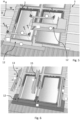
Fig. 1 is a perspective schematic view of two roof windows mounted side by side with a prior art flashing assembly, adapted by the incorporation of reference numerals corresponding to embodiments of the present invention; - Fig. 2 is a perspective schematic view of four windows mounted two by two in a matrix configuration, adapted only by the incorporation of a few reference numerals corresponding to embodiments of the present invention;
-
Fig. 3 is a sketch showing general engagement means by a separate connection piece; -
Fig. 4 is a view of the engagement between flashing elements in an embodiment of the flashing assembly according to the invention; -
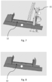
Figs 5-8 are perspective views depicting steps in a method for mounting a flashing assembly; -
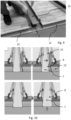
Fig. 9 shows a photograph showing a step of a method for mounting a flashing assembly where the flashing assembly is provided in an assembled state; -
Fig. 10 are perspective views depicting steps in a method for mounting a flashing assembly where the flashing assembly is provided in an assembled state; -
Fig. 11 shows sequential photographs depicting steps of a method for mounting a flashing assembly; -
Fig. 12 shows a photograph depicting a step of a method for mounting a flashing assembly; -
Fig. 13 shows a detail ofFig. 12 ; -
Fig. 14 is a view corresponding toFig. 4 , representing the attained step of a method for mounting a flashing assembly corresponding toFig. 12 ; -
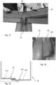
Figs 15 and 16 show sequential photographs depicting steps in a method for mounting a flashing assembly; -
Fig. 17 shows a photograph depicting a step of a method for mounting a flashing assembly; -
Fig. 18 shows a photograph of a detail corresponding to the stepFig. 17 ; -
Fig. 19 is a view corresponding toFig. 4 andFig. 14 , representing the attained step of a method for mounting a flashing assembly corresponding toFig. 17 ; -
Fig. 20 shows a photograph depicting a step of a method for mounting a flashing assembly; -
Fig. 21 is a view corresponding toFigs 4 ,14 and19 , representing the attained step of a method for mounting a flashing assembly corresponding toFig. 20 ; -
Fig. 22 shows a photograph depicting a step of a method for mounting a flashing assembly; and -
Fig. 23 is a view corresponding toFigs 4 ,14 ,19 and21 , representing the attained step of a method for mounting a flashing assembly corresponding toFig. 22 . - Referring initially to
Fig. 1 , a priorart flashing assembly 1 for use with two roof windows mounted adjacent to each other side by side in asloped roof structure 3 is shown. It is noted that the prior art figure has been adapted by the incorporation of reference numerals corresponding to embodiments of the present invention. As the construction of the roof windows are not of importance, they are here represented only by twoframes 2, each comprising atop frame member 21 and abottom frame member 22 both extending horizontally in the mounted state and twoside frame members roof structure 3 is represented only by a single rafter and a few laths and the slope direction is indicated by the arrow D. For a reference to other orthogonal directions as defined in the present application, namely a width direction W and a height direction H, seeFig. 5 . - The flashing
assembly 1 comprises twotop flashing elements 11 each configured for extending along atop frame member 21, twobottom flashing elements 12 each configured for extending along abottom frame member 22, twoside flashing elements side frame member gutter flashing element 15 configured for extending between the two roof windows. Common to all flashing elements is that they comprise anouter portion inner portion - The
top flashing elements 11 and thebottom flashing elements 12 are provided with corner sections, 113, 114, 123, 124 configured for establishing an overlap with theside flashing elements gutter flashing element 15, andcover members corner sections 114 of the top flashing elements above the middle gutter flashing element. - In
Fig. 1 , the flashingassembly 1 is configured for use with roof windows mounted deep in a roof structure, and theside flashing elements side frame member 23 and at a right-handside flashing element 14 of a roof window, respectively. The same applies to the twotop flashing elements 11 and the twobottom flashing elements 12. - In Fig. 2 a corresponding flashing assembly for four roof window mounted in a two-by-two configuration is shown. It includes two middle
gutter flashing elements 15 corresponding to the one inFig. 1 and extending between the two columns of roof windows, and twodrainage gutter elements 18 extending horizontally between the two rows of roof windows. -
Fig. 3 shows a sketch of general engagement means between two elements making use of a separate cover member. - In the following description of embodiments of the invention, reference numerals as per the above will be applied for components having the same or analogous function. This is not and should not be seen as a concession to such components being identical to components of the prior art.
- Referring now to
Fig. 4 , which shows the principles of the engagement between two flashing elements, the configuration of a flashingassembly 1 in an embodiment of the invention will be described. The flashingassembly 1 is intended for use between tworoof windows 2, which are mounted side by side in aninclined roof structure 3 and which each comprises a frame and a pane element. Reference is also being made toFig. 5 including the indication of the height direction H, the width direction W and the slope direction D. All directional axes are to be referenced to such directions. - The flashing
assembly 1 comprises a first flashing element generally designated 7 and configured for extending along a frame member of the frame of a first roof window and a second flashing element generally designated 8 configured for extending along a frame member of the frame of a second roof window. - Each flashing
element first section second section first section flashing element assembly 1. Thus, thefirst section first section second section flashing element second section - The
first section 71 of thefirst flashing element 7 comprises twolegs pocket 713 between them. As shown in the lower part ofFig. 4 , thefirst section 81 of thesecond flashing element 8 fits into the pocket of the first flashing element. - Further details visible in the embodiment of the flashing
assembly 1 shown inFig. 4 include the feature that the one of the twolegs 712 of thefirst section 71 of thefirst flashing element 7 located furthest from the second edge of the second section of the first flashing element has aflange 71a projecting along the height axis in an exterior direction away from the interior side of the first section toward the other of the two legs. Correspondingly, thefirst section 81 of the second flashing element has aflange 81a projecting along the height axis in an interior direction. - The
flanges flashing elements second sections flashing elements - The material of both flashing
elements - Suitable dimensions of the flashing elements of the flashing assembly are given in the following: Where the first section of the second flashing element has a width measured along the width axis from the second section to an edge opposite the second section, where the pocket of the first section of the first flashing element has a depth measured along the width axis from the second section to an edge of the shorter of the two legs, and where said width of the first section of the second flashing element is at least 1.1 times the depth of the pocket.
- While
reference numerals assembly 1. - Thus, the first and second flashing element may constitute side flashing elements configured for extending along a
side frame member assembly 1 formed by them, may replace middlegutter flashing elements 15 orside flashing elements Figs 1 and 2. - Additionally or alternatively, the first and second flashing element are top flashing elements configured for extending along
top frame member 21 of the roof windows, bottom flashing elements configured for extending alongbottom frame member 22 of the roof windows, or gutter flashing elements configured for use between roof windows arranged above each other. Comparing with the prior art flashing assembly, it is thus possible to apply the principles underlying the invention to thetop flashing element 12, thebottom flashing element 13 and thedrainage gutter element 18. - Referring now also to
Figs 5-23 , a method for mounting a flashing assembly between two roof windows which are mounted side by side in an inclined roof will be described. - The steps comprised by the method include:
- arranging a
first flashing element 7 of a middlegutter flashing element 15 so that it extends along a frame member of theframe 2 of a first roof window with afirst section 71 extending between the two roof windows, with an interior side of the first section facing the roof structure, with asecond section 72 extending along a height axis in an exterior direction, and with an interior side of the second section facing the frame of the first roof window, - arranging a
second flashing element 8 of the middlegutter flashing element 15 so that it extends along a frame member of theframe 2 of a second roof window with afirst section 81 extending between the two roof windows, with an interior side of the first section facing the roof structure, with asecond section 82 extending in an exterior direction, and with an interior side of the second section facing the frame of the second roof window, - whereby the
first section 81 of thesecond flashing element 8 is inserted into apocket 713 of thefirst section 71 of thefirst flashing element 7, saidpocket 713 being formed by twolegs - The method may be carried out such that the
first section 81 of thesecond flashing element 8 is initially inserted fully into thepocket 713 of the first flashing element 7 (see, for example,Fig. 9 ), and where theflashing elements second sections Fig. 10 ). - As is apparent from the illustrations, the
first flashing element 7 is generally mounted, i.e., connected to a frame of a first window, before thesecond flashing element 8 , i.e., connected to a frame of a second window (see, for example,Fig. 10 , upper left image). - In some installation conditions, the first section of the second flashing element is bending during the insertion into the pocket.
- To adjust the width to the desired dimension, the first section of the second flashing element may be inserted fully into the pocket of the first flashing element, and where the second flashing elements is subsequently pulled back until the second section of the second flashing element comes into contact with the frame of the second roof window.
- In
Figs 11-14 a left-handdrainage gutter element 18 is attached to the middlegutter flashing element 15 shown inFigs 5-10 by hooking onto theupper leg 711 of the two legs forming thepocket 713 as best seen inFig. 11 and14 . - In
Figs 15-19 a right-hand drainage gutter element 18' is attached to the middlegutter flashing element 15 shown inFigs 5-10 by inserting thefirst section 181 into thepocket 713 as best seen inFigs 18-19 . During the insertion into the pocket, the first section is bending as best seen inFig. 16 . -
Figs. 20-21 show the mounting of a left-handtop flashing elements 11, which is interconnected with a middlegutter flashing element 15 in the same way as described for the left-handdrainage gutter element 18 inFigs 11-14 , andFigs 22-23 show the mounting of a right-hand top flashing elements 11' in the same way as described for the right-hand drainage gutter element 18' inFigs 15-19 . -
- 1 flashing assembly
- 2 frame
- 21 top frame member
- 22 bottom frame member
- 23 side frame member
- 24 side frame member
- 3 roof structure
- 7 first flashing element
- 71 first section
- 71a flange
- 711 leg
- 712 leg
- 713 pocket
- 72 second section
- 8 second flashing element
- 81 first section
- 81a flange
- 82 second section
- 11 top flashing element
- 111 outer portion
- 112 inner portion
- 113 corner section
- 114 corner section
- 12 bottom flashing element
- 121 outer portion
- 122 inner portion
- 123 corner section
- 124 corner section
- 13 side flashing element
- 131 outer portion
- 132 inner portion
- 14 side flashing element
- 141 outer portion
- 142 inner portion
- 15 middle gutter flashing element
- 16 cover member
- 17 cover member
- 18 drainage gutter element
- D slope direction
- W width direction
- H height direction
Claims (14)
- A flashing assembly for use between two roof windows, which are mounted side by side in an inclined roof structure and which each comprises a frame and a pane element, said flashing assembly comprising a first flashing element configured for extending along a frame member of the frame of a first roof window and a second flashing element configured for extending along a frame member of the frame of a second roof window, each flashing element comprising a first section and a second section, said first section extending along a width axis of the flashing element, being configured for extending between the first roof window and the second roof window, and having an interior side configured for facing the roof structure, and said second section extending in an exterior direction along a height axis of the flashing element and having an interior side configured for facing the frame of one of the roof windows, said second section having a first edge at the first section and a second edge located at distance from the first section measured along the height axis,
characterised in that the first section of the first flashing element comprises two legs extending along the width axis and being located at a distance from each other measured along the height axis thereby forming a pocket between them, and that the first section of the second flashing element fits into the pocket of the first flashing element. - A flashing assembly according to claim 1, where the one of the two legs of the first section of the first flashing element located furthest from the second edge of the second section of the first flashing element has a flange projecting along the height axis in an exterior direction away from the interior side of the first section toward the other of the two legs, and where the first section of the second flashing element has a flange projecting along the height axis in an interior direction.
- A flashing assembly according to claim 2, where the flanges of the flashing elements each extends at an angle of more than 90 degrees in relation to the width axis so that they project back towards the respective second sections of the flashing elements.
- A flashing assembly according to one or more of the previous claims, where both flashing elements are made from sheet metal, preferably from aluminium or copper.
- A flashing assembly according to one or more of the previous claims, where the first and second flashing element are side flashing elements configured for extending along a side frame member of the roof windows.
- A flashing assembly according to one or more of the previous claims, where the first and second flashing element are top flashing elements configured for extending along top frame member of the roof windows, bottom flashing elements configured for extending along bottom frame member of the roof windows, or gutter flashing elements configured for use between roof windows arranged above each other.
- A flashing assembly according to one or more of the previous claims, where the first section of the second flashing element has a width measured along the width axis from the second section to an edge opposite the second section, where the pocket of the first section of the first flashing element has a depth measured along the width axis from the second section to an edge of the shorter of the two legs, and where said width of the first section of the second flashing element is at least 1.1 times the depth of the pocket.
- A group of roof windows including at least two roof windows mounted side by side in an inclined roof structure using a flashing assembly according to one or more of claims 1-7.
- A group of roof windows according to claim 8, where the total width of the first sections of the two flashing elements when the first section of the second flashing element is inserted fully into a pocket of the first section of the first flashing element is smaller than the distance between the two roof windows.
- A method for mounting a flashing assembly between two roof windows, which are mounted side by side in an inclined roof structure and which each comprises a frame and a pane element, said method comprising:arranging a first flashing element so that it extends along a frame member of the frame of a first roof window with a first section extending between the two roof windows, with an interior side of the first section facing the roof structure, with a second section extending along a height axis in an exterior direction, and with an interior side of the second section facing the frame of the first roof window,arranging a second flashing element so that it extends along a frame member of the frame of a second roof window with a first section extending between the two roof windows, with an interior side of the first section facing the roof structure, with a second section extending in an exterior direction, and with an interior side of the second section facing the frame of the second roof window,characterised in that the first section of the second flashing element is inserted into a pocket of the first section of the first flashing element, said pocket being formed by two legs extending along a width axis and being located at a distance from each other measured along the height axis.
- A method according to claim 10, where the first section of the second flashing element is initially inserted fully into the pocket of the first flashing element, and where the flashing elements are subsequently pulled away from each other until the second sections of the flashing elements come into contact with the frames of the roof windows.
- A method according to claim 11, where the first flashing element is mounted before the second flashing element.
- A method according to one or more of claims 10-12, where, during the insertion into the pocket, the first section of the second flashing element is bending.
- A method according to one or more of claims 10-13, where the first section of the second flashing element is inserted fully into the pocket of the first flashing element, and where the second flashing element is subsequently pulled back until the second section of the second flashing element comes into contact with the frame of the second roof window.
Applications Claiming Priority (1)
| Application Number | Priority Date | Filing Date | Title |
|---|---|---|---|
| DKPA202370172 | 2023-04-05 |
Publications (1)
| Publication Number | Publication Date |
|---|---|
| EP4442924A1 true EP4442924A1 (en) | 2024-10-09 |
Family
ID=90718764
Family Applications (1)
| Application Number | Title | Priority Date | Filing Date |
|---|---|---|---|
| EP24168726.8A Pending EP4442924A1 (en) | 2023-04-05 | 2024-04-05 | A flashing assembly for use between two roof windows mounted in an inclined roof structure, a group of roof windows mounted using such a flashing assembly, and a method for mounting a flashing assembly between two roof windows |
Country Status (3)
| Country | Link |
|---|---|
| US (1) | US20240337108A1 (en) |
| EP (1) | EP4442924A1 (en) |
| CN (1) | CN222575969U (en) |
Cited By (2)
| Publication number | Priority date | Publication date | Assignee | Title |
|---|---|---|---|---|
| EP4722463A1 (en) * | 2024-10-04 | 2026-04-08 | VKR Holding A/S | A flashing assembly for use between two roof windows mounted in an inclined roof structure, a group of roof windows mounted with such a flashing assembly, and a method for mounting a flashing assembly between two roof windows |
| EP4722465A2 (en) | 2024-10-04 | 2026-04-08 | VKR Holding A/S | A kit of covering members, a method of manufacturing a kit of covering members, and use of the kit of covering members |
Families Citing this family (1)
| Publication number | Priority date | Publication date | Assignee | Title |
|---|---|---|---|---|
| USD957003S1 (en) * | 2019-09-25 | 2022-07-05 | Vkr Holding A/S | Window accessory |
Citations (5)
| Publication number | Priority date | Publication date | Assignee | Title |
|---|---|---|---|---|
| DK154099B (en) | 1982-02-26 | 1988-10-10 | Rasmussen Holding As V Kann | COMBINATION COVER FRAME FOR ROOF WINDOWS TO BE BUILT IN SIDE OF THE HIND |
| WO2003074812A1 (en) | 2002-03-07 | 2003-09-12 | Vkr Holding A/S | Sheet flashing member and flashing kit comprising such sheet flashing members |
| EP1521888B1 (en) * | 2002-07-17 | 2010-11-24 | VKR Holding A/S | Sheet flashing member and a flashing kit |
| PL70359Y1 (en) * | 2016-11-30 | 2018-11-30 | Fakro Pp Spolka Z Ograniczona Odpowiedzialnoscia | Roof window flashings that seals coupling of a roof window with photovoltaic panel |
| EP3480388A1 (en) * | 2017-11-03 | 2019-05-08 | VKR Holding A/S | A flashing member for a roof element, such as a roof window, and a flashing kit |
-
2024
- 2024-04-02 CN CN202420671318.1U patent/CN222575969U/en active Active
- 2024-04-04 US US18/626,522 patent/US20240337108A1/en active Pending
- 2024-04-05 EP EP24168726.8A patent/EP4442924A1/en active Pending
Patent Citations (5)
| Publication number | Priority date | Publication date | Assignee | Title |
|---|---|---|---|---|
| DK154099B (en) | 1982-02-26 | 1988-10-10 | Rasmussen Holding As V Kann | COMBINATION COVER FRAME FOR ROOF WINDOWS TO BE BUILT IN SIDE OF THE HIND |
| WO2003074812A1 (en) | 2002-03-07 | 2003-09-12 | Vkr Holding A/S | Sheet flashing member and flashing kit comprising such sheet flashing members |
| EP1521888B1 (en) * | 2002-07-17 | 2010-11-24 | VKR Holding A/S | Sheet flashing member and a flashing kit |
| PL70359Y1 (en) * | 2016-11-30 | 2018-11-30 | Fakro Pp Spolka Z Ograniczona Odpowiedzialnoscia | Roof window flashings that seals coupling of a roof window with photovoltaic panel |
| EP3480388A1 (en) * | 2017-11-03 | 2019-05-08 | VKR Holding A/S | A flashing member for a roof element, such as a roof window, and a flashing kit |
Cited By (2)
| Publication number | Priority date | Publication date | Assignee | Title |
|---|---|---|---|---|
| EP4722463A1 (en) * | 2024-10-04 | 2026-04-08 | VKR Holding A/S | A flashing assembly for use between two roof windows mounted in an inclined roof structure, a group of roof windows mounted with such a flashing assembly, and a method for mounting a flashing assembly between two roof windows |
| EP4722465A2 (en) | 2024-10-04 | 2026-04-08 | VKR Holding A/S | A kit of covering members, a method of manufacturing a kit of covering members, and use of the kit of covering members |
Also Published As
| Publication number | Publication date |
|---|---|
| CN222575969U (en) | 2025-03-07 |
| US20240337108A1 (en) | 2024-10-10 |
Similar Documents
| Publication | Publication Date | Title |
|---|---|---|
| US20240337108A1 (en) | Flashing assembly for use between two roof windows mounted in an inclined roof structure, a group of roof windows mounted using such a flashing assembly, and a method for mounting a flashing assembly between two roof windows | |
| EP0087647B1 (en) | Combined covering frame for skylights embedded side by side | |
| DE69901823T2 (en) | SEALING ELEMENT AND FRAME FOR A BUILDING ELEMENT THROUGH THE ROOF | |
| EP3966401B1 (en) | Flashing assembly for a roof penetrating structure and a method for manufacturing a flashing assembly | |
| EP3404162B1 (en) | A roof window installed in an inclined roof structure with a flashing assembly and a method for weather proofing a roof window | |
| EP1485547B1 (en) | Flashing kit | |
| CN209891586U (en) | Waterproof external member | |
| EP3263797A1 (en) | A roof window and a sloping roof structure | |
| US12421728B2 (en) | Roof window, a kit with a covering assembly, and a method for mounting a roof window | |
| DE69513162T2 (en) | CONNECTING STRIP FOR ROOF ELEMENTS | |
| US20240328162A1 (en) | Flashing assembly comprising a top flashing arrangement, a roof element system comprising such a flashing assembly, and a method of manufacturing a flashing assembly | |
| EP1567732B1 (en) | A flashing device and a method of installing a roof penetrating structure by means of the flashing device | |
| EP3404161B1 (en) | A flashing assembly and a method for weather proofing a roof window mounted in an inclined roof surface | |
| EP3031997A2 (en) | System for covering openings on roofs | |
| US20260098407A1 (en) | Flashing assembly for use between two roof windows mounted in an inclined roof structure, a group of roof windows mounted with such a flashing assembly, and a method for mounting a flashing assembly between two roof windows | |
| AU765155B2 (en) | Frame structure | |
| DE19606442C1 (en) | Plastics or aluminium@ roofing | |
| EP3670779A1 (en) | A flashing element for a roof window and a method for making a flashing element | |
| JPH06288044A (en) | Connection structure of horizontal roof panel structural material and horizontal roof panel structural material used therefor | |
| DE10064880A1 (en) | Pantile, especially as unit for entry of sloping roof, has hooks for support on next lower lying roof tile, and on upper end has means for fastening on next higher lying roof batten or rafter | |
| DE102005002635A1 (en) | Covering sheet plate mounting system for building e.g. airport, has holding rails provided between sub-structure of building and holding units, where base parts of holding units are displaced in holding rail in profile direction of plate |
Legal Events
| Date | Code | Title | Description |
|---|---|---|---|
| PUAI | Public reference made under article 153(3) epc to a published international application that has entered the european phase |
Free format text: ORIGINAL CODE: 0009012 |
|
| STAA | Information on the status of an ep patent application or granted ep patent |
Free format text: STATUS: THE APPLICATION HAS BEEN PUBLISHED |
|
| AK | Designated contracting states |
Kind code of ref document: A1 Designated state(s): AL AT BE BG CH CY CZ DE DK EE ES FI FR GB GR HR HU IE IS IT LI LT LU LV MC ME MK MT NL NO PL PT RO RS SE SI SK SM TR |
|
| RIN1 | Information on inventor provided before grant (corrected) |
Inventor name: SCHMIDT, BIRGIT Inventor name: ANDERSEN, BJARNE ANDRES Inventor name: LUND, JAKOB SWANE Inventor name: GRONBAEK, KRISTIAN STRAND Inventor name: HENRIKSEN, JENS-ULRIK HOLST Inventor name: ANDERSEN, RASMUS |
|
| STAA | Information on the status of an ep patent application or granted ep patent |
Free format text: STATUS: REQUEST FOR EXAMINATION WAS MADE |
|
| 17P | Request for examination filed |
Effective date: 20250408 |