EP4442922A1 - A bottom flashing member cutting guide, a cardboard packaging, and a method of flashing a roof element - Google Patents
A bottom flashing member cutting guide, a cardboard packaging, and a method of flashing a roof element Download PDFInfo
- Publication number
- EP4442922A1 EP4442922A1 EP24166262.6A EP24166262A EP4442922A1 EP 4442922 A1 EP4442922 A1 EP 4442922A1 EP 24166262 A EP24166262 A EP 24166262A EP 4442922 A1 EP4442922 A1 EP 4442922A1
- Authority
- EP
- European Patent Office
- Prior art keywords
- base
- cutting guide
- side edge
- bottom flashing
- flashing member
- Prior art date
- Legal status (The legal status is an assumption and is not a legal conclusion. Google has not performed a legal analysis and makes no representation as to the accuracy of the status listed.)
- Pending
Links
Images



Classifications
-
- E—FIXED CONSTRUCTIONS
- E04—BUILDING
- E04D—ROOF COVERINGS; SKY-LIGHTS; GUTTERS; ROOF-WORKING TOOLS
- E04D13/00—Special arrangements or devices in connection with roof coverings; Protection against birds; Roof drainage ; Sky-lights
- E04D13/14—Junctions of roof sheathings to chimneys or other parts extending above the roof
- E04D13/147—Junctions of roof sheathings to chimneys or other parts extending above the roof specially adapted for inclined roofs
- E04D13/1473—Junctions of roof sheathings to chimneys or other parts extending above the roof specially adapted for inclined roofs specially adapted to the cross-section of the parts extending above the roof
- E04D13/1475—Junctions of roof sheathings to chimneys or other parts extending above the roof specially adapted for inclined roofs specially adapted to the cross-section of the parts extending above the roof wherein the parts extending above the roof have a generally rectangular cross-section
-
- E—FIXED CONSTRUCTIONS
- E04—BUILDING
- E04D—ROOF COVERINGS; SKY-LIGHTS; GUTTERS; ROOF-WORKING TOOLS
- E04D15/00—Apparatus or tools for roof working
Definitions
- the present invention relates to a bottom flashing member cutting guide for guiding cutting of a bottom flashing member for a roof penetrating element. Further the invention relates to a cardboard packaging, especially a corrugated cardboard packaging, preferably for a bottom flashing member, and to a method of flashing a roof element in a roof comprising flat roofing panels interconnected through standing seams.
- EP 4279684 A1 A method of the above-mentioned art is disclosed in EP 4279684 A1 and the method involves making a cut-out in a bottom flashing member to accommodate a lower part of a cover device for covering a cut upper edge and an adjacent part of a standing seam.
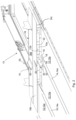
- Fig. 1 shows a roof window installed using the device and method disclosed in EP23174077.0 and Fig. 2 illustrate the method disclosed in EP23174077.0 .
- Fig. 1 shows a a roof penetrating element, in the present example a roof window 10 installed and flashed in a sloping roof with a roof covering comprising flat roofing panels 12, 12a interconnected by rigid, standing seams 14, 14a.
- flashing members which comprise i.a. a bottom flashing member 16 having at least a section with a generally L-shaped cross-section with a first leg 16a configured to be arranged against a side of the roof window and a second leg 16b configured to be at least in part positioned above the roof covering to seal between the roof window and the roof covering.
- the roof window 10 is mounting in a slanted roof with a roof covering comprising the flat roofing panels 12, 12a interconnected by the standing seams 14, 14a.
- flashing members are used including a bottom flashing member 16 for flashing along a lower side 10a of the window 10.
- the bottom flashing member 16 has a section with a generally L-shaped cross-section with a first leg 16a configured to be arranged against the lower side 10a of the window and a second leg 16b configured to be at least in part positioned above the flat roofing panels 12a to seal between the window 10 and the roof covering.
- the cover device comprises a lower part 30 and an upper part 50.
- Embodiments of the cover device comprising the lower part 30 and the upper part 50 are disclosed in EP 4279684 A1 .
- the cover device provides for a method of flashing a roof element, the method comprising the steps of:
- means are provided for releasably connecting the two parts 30, 50 and more specifically, in the present embodiment these means comprise a screw 53 for penetrating the upper part 50 to be screwed into a hole provided in the lower part 30 for accepting the screw 53. Further a flap is provided on the upper part 50 for folding around an edge on the lower part.
- the first object is obtained by a bottom flashing member cutting guide, said bottom flashing member cutting guide comprising a base having a first side edge and a track extending, at least from the vicinity of the first side edge into the base; and two angle portions depending from the base and limiting an opening adjoining said track in the base, wherein said track has a width in a direction along the first side edge, the two angle portions respectively have a second side edge and a third side edge, the second side edge and the third side edge defining the opening, the third side edge being vis-à-vis the second side edge, a mutual distance between the second side edge and the third side edge being smaller than the width of the track.
- the bottom flashing member cutting guide may be fitted on top of the second leg of the bottom flashing element, the two angle portions straddling an underlying one of the standing seams, whereby the track will provide a convenient guide for cutting or marking for cutting the bottom flashing element to accommodate the lower part of the cover device.
- the two angle portions depending from the base are connected to the base by connections to extend at angles relative to the base, said connections being flexible whereby said angles are adjustable.
- the angles are adjustable the two angle portions may be rotated for better fit with the underlying standing seem in case the cutting guide does not exactly match the profile of the standing seems of the roof covering in question including the standing seems.
- the two angle portions depending from the base are connected to the base by connections to extend at angles relative to the base, said connections being rigid to keep said angles constant, preferably at right angles.
- the track is defined by at least one recessed portion recessed in the base. This facilitates using e.g. a pencil for marking the bottom flashing member for subsequent cutting.
- the second side edge and third side edge define straight lines that extend mutually diverging away from the base to define an angle between them.
- the angle may match an angle between opposing sides of the standing seem being straddled for a better match with the standing seem to facilitate positioning the cutting guide correctly.
- the bottom flashing member cutting guide comprises a flat material. This provides for a simple and cost-effective cutting guide.
- the material is a paper-based material, preferably cardboard, more preferably corrugated cardboard. This provides for an environment-friendly cutting guide free of plastic.
- the object is further obtained by a cardboard packaging, especially a corrugated cardboard packaging, preferably for a bottom flashing member, said cardboard packaging comprising a section of cardboard material having a surface, wherein the outlines of a base, a track, and two angle portions of a bottom flashing member cutting guide according to the present invention as outlined above, are marked on said surface.
- the line circumscribing the base and the two angle portions may be a score line providing for tearing or pushing the base together with the two angle portions, and preferably also together with a piece of material between the two angle portions, from the section of cardboard material.
- the outlines comprise a straight line separating the base and the angle portions.
- a straight line separating the base from the two angle portions to facilitate a correct manual bending of the cardboard material at the connection between the base and the two angle portions.
- the outlining outlines may include visual markings and/or score lines. Using only visual markings the cutting guide may be cut from the packaging and the track may be cut open to provide for marking the bottom flashing member with a pen or a pencil. Using score lines, these lines may facilitate manual tearing the cutting guide from the cardboard packaging for ease of operation.
- Score lines may be provided in a material e.g. by cutting lines in the surface of the material, or by embossing or perforating lines in the material, etc.
- the packaging comprising two sides of cardboard material meeting at a corner of the packaging, a part of a first side of said two sides constituting the base of a bottom flashing member cutting guide according to any one of the preceding claims, and a part of a second side of said two sides constituting the two angle portions of said bottom flashing member cutting guide, whereby an outline of the base and the two angle portions, including outlines of the track and the second side edge and third side edge of the bottom flashing member cutting guide is marked on said first side and said second side, respectively.
- the object is further obtained by a method of flashing a roof element in a roof comprising flat roofing panels interconnected through standing seams, the method comprising the steps of:
- Using the cutting guide according to the invention facilitates the provision of the cut-out in the bottom flashing member.
- the bottom flashing member may be marked using e.g. a pen or a pencil inserted through the track when the track is recessed to allow the pen or pencil to be inserted through the cutting guide to the surface of the bottom flashing member.
- the material of the cutting guide is e.g. cardboard
- the making of the cut-out involves removing the bottom flashing member cutting guide from the cardboard packaging, and at least removing a piece of cardboard material between the second side edge and the third side edge.
- the present invention provides a bottom flashing member cutting guide, in the following referred to as "cutting guide", 60 for facilitating the provision of the above-mentioned cut-out 20.
- the cutting guide comprises a base 601 having a first side edge 602 and a track 603 extending, at least from the vicinity of the first side edge 602 into the base 601, and two angle portions 604; 605 depending from the base 601 and limiting an opening 606 adjoining said track 603 in the base 601.
- the track 603 has a width w in a direction x along the first side edge 602.
- the two angle portions 604; 605 respectively have a second side edge 607 and a third side edge 608.
- the second side edge 607 and the third side edge 608 are defining the opening 606, the third side edge 608 being vis-à-vis the second side edge 607.
- a mutual distance d between the second side edge 607 and the third side edge 608 is smaller than the width w of the track 603.
- the two angle portions 604; 605 depending from the base 601 are connected to the base by connections 604a; 605a to extend at angles ⁇ relative to the base 601.
- the connections 604a; 605a may be flexible whereby the angles ⁇ are adjustable or the connections 604a; 605a may be rigid to keep said angles ⁇ constant, preferably at right angles.
- the track 603 may be defined by at least one recessed portion recessed in the base 601.
- the second side edge 607 and third side edge 608 define straight lines 607a; 608a that extend mutually diverging away from the base to define an angle ⁇ between them.
- the bottom flashing member cutting guide 60 comprises a flat material, and especially, as will be explained below with reference to Figs. 3 and 4 , the material may be a paper-based material, especially cardboard, and preferably corrugated cardboard.
- each cut-out 20 is provided as follows: The bottom flashing element 16 is positioned loosely against the lower side 10a of the roof element 10 and on top of the standing seams 14a,
- the marking may be made initially, e.g. by means of a pen or a pencil 80 as indicated in Fig. 3 for the second leg 16b to be cut subsequently, or the marking may be dispensed with, and the cutting be made directly.
- the cutting guide 60 may be made of any suited material, but, referring to Fig. 4 , in a preferred embodiment the cutting guide may be provided by a cardboard packaging 70, especially a corrugated cardboard packaging, e.g. for a bottom flashing member 16, said cardboard packaging comprising a section of cardboard material 701 having a surface 701a, wherein the outlines 704, 705, 706, 707 of a base 601, a track 603, and two angle portions 604; 605 of a bottom flashing member cutting guide 60 according to the present invention, are marked on said surface 701a.
- the outlining outlines 704, 705, 706, 707 may e.g. include visual markings and/or score lines.
- the outlines comprise a line 702 connecting distal ends of the angle portions 604; 605 distal from the base 601.
- the line 702 distal ends of the angle portions 604; 605 distal from the base 601 and delimitations of the distal ends of the angle portions 604; 605 distal from the base 601 are provided by a free edge of the section of cardboard material 701 and in this case further separation there along is not necessary.
- the outlines comprise a straight line 703 separating the base 601 and the angle portions 604; 605.
- the straight line 703 separating the base 601 and the angle portions 604; 605 facilitates bending the angle portions 604; 605 at angles ⁇ relative to the base 601 in a correct manner to ensure that the track 603 will be positioned centrally relative to the standing seam 14a when the cutting guide is positioned as shown in Fig. 3 and explained above.
- the section of cardboard material comprises two sides meeting at a corner of the packaging, a part of a first side of said two sides constituting the base of the bottom flashing member cutting guide, and a part of a second side of said two sides constituting the two angle portions, whereby an outline of the base and the two angle portions, including outlines of the track and the second side edge and third side edge of the bottom flashing member cutting guide is marked on said first side and said second side, respectively.
- a piece of cardboard material 708 basically corresponding to the track 603 may be removed. At least a piece of cardboard material 708a between the two angle portions 604; 605 should be removed in order to allow the latter to straddle the standing seam 14a.
- the cutting guide 60 including the track 603 will be positioned centrally relative to the standing seam 14a to provide for a correctly positioned cut-out 20 for accommodating the lower part 30 of the cover device during installation of the flashing.
- the cut-out 20 may be provided with a sufficient width to accommodate the lower part 30 of the cover device.
- the angle ⁇ should me adjusted to get the cutting guide 60 correctly and centrally positioned relative to the standing seam 14a.
- the track is merely marked, and in such case, it is possible to insert e.g. a pointed knife through the material of the cutting guide and e.g. mark the bottom flashing element by cutting the surface thereof while cutting through the material of the cutting guide following the marked track. Subsequently the bottom flashing element may be cut using e.g. a pair of shears to finalize the cut-out 20.
Landscapes
- Engineering & Computer Science (AREA)
- Architecture (AREA)
- Civil Engineering (AREA)
- Structural Engineering (AREA)
- Cartons (AREA)
Abstract
A bottom flashing member cutting guide (60) for guiding cutting of a bottom flashing member (16), comprises a base having a first side edge and a track (603) with a width, extending from the first side edge into the base; and two angle portions (604; 605) depending from the base and limiting an opening adjoining said track (603). The two angle portions (604; 605) respectively have a second side edge and a third side edge which together define the opening (606). A mutual distance (d) between the second side edge and the third side edge is smaller than the width of the track (603).The cutting guide (60) may be provided from the material of a cardboard packaging.During flashing a roof penetrating element in a roof comprising standing seems (14a) the cutting guide may be used when providing cut-outs for accommodating an element for covering the standing seem (14a).
Description
- The present invention relates to a bottom flashing member cutting guide for guiding cutting of a bottom flashing member for a roof penetrating element. Further the invention relates to a cardboard packaging, especially a corrugated cardboard packaging, preferably for a bottom flashing member, and to a method of flashing a roof element in a roof comprising flat roofing panels interconnected through standing seams.
- A method of the above-mentioned art is disclosed in
EP 4279684 A1 and the method involves making a cut-out in a bottom flashing member to accommodate a lower part of a cover device for covering a cut upper edge and an adjacent part of a standing seam. -
Fig. 1 shows a roof window installed using the device and method disclosed inEP23174077.0 Fig. 2 illustrate the method disclosed inEP23174077.0 - Thus,
Fig. 1 shows a a roof penetrating element, in the present example aroof window 10 installed and flashed in a sloping roof with a roof covering comprisingflat roofing panels seams - For flashing the window, flashing members are used which comprise i.a. a
bottom flashing member 16 having at least a section with a generally L-shaped cross-section with afirst leg 16a configured to be arranged against a side of the roof window and asecond leg 16b configured to be at least in part positioned above the roof covering to seal between the roof window and the roof covering. - Referring further to
Fig. 2 , theroof window 10 is mounting in a slanted roof with a roof covering comprising theflat roofing panels seams window 10, flashing members are used including abottom flashing member 16 for flashing along alower side 10a of thewindow 10. Thebottom flashing member 16 has a section with a generally L-shaped cross-section with afirst leg 16a configured to be arranged against thelower side 10a of the window and asecond leg 16b configured to be at least in part positioned above theflat roofing panels 12a to seal between thewindow 10 and the roof covering. - Due to the cover device, it is possible to install the bottom flashing member 16 (see
Fig. 2 ) with itssecond leg 16b abutting or in close proximity to the surface offlat roofing panels 12a between standingseams 14a interconnecting the same. - Thus, to provide for the
second leg 16b of thebottom flashing member 16 abutting or being in close proximity to the surface of theflat roofing panels 12a between the standingseams 14a, the cover device comprises alower part 30 and anupper part 50. - Embodiments of the cover device comprising the
lower part 30 and theupper part 50 are disclosed inEP 4279684 A1 . - The function of the cover device will now be described, referring to
Fig. 2 , by explaining the method of flashing thewindow 10. - Thus, the cover device provides for a method of flashing a roof element, the method comprising the steps of:
- a) mounting a full roofing panel 12 (see
Fig. 1 ) at a first side of thewindow 10; - b) mounting
lower roofing panels 12a below thewindow 10,seams 14a between thelower roofing panels 12a extending down the roof from a position adjacent alower side 10a of thewindow 10; - c) for each standing
seam 14a betweenlower roofing panels 12a, removing part of the standingseam 14a between thelower roofing panels 12a from anupper edge 12b thereof proximal the window and a predetermined distance away from the window leaving a cutupper edge 18 of the respective standingseam 14a and agap 19 between adjacent cut edges of thelower roofing panels 12a; - d) mounting the
lower part 30 of the device to cover saidupper edge 18 and the adjacent part of the standingseam 14a; - e) making for each cut standing seam, a cut-out 20 at a
lower edge 22 of thebottom flashing member 16 to accommodate a raisedwall 35 of thelower part 30 of the device; - f) mounting the
bottom flashing member 16; and - g) for each
cut standing edge 14a, mounting theupper part 50 of the device whereby acover portion 51 of theupper part 50 is placed over anelongated recess 32 of thelower part 30. - Hereby the flashing of the
lower edge 22 of thewindow 10 is finished, the upper cut edge(s) 18 being flashed by means of the cover device including to the twoparts - In the present embodiment means are provided for releasably connecting the two
parts screw 53 for penetrating theupper part 50 to be screwed into a hole provided in thelower part 30 for accepting thescrew 53. Further a flap is provided on theupper part 50 for folding around an edge on the lower part. - It is a first object of the present invention to facilitate said making of a cut-out.
- It is a further object to provide an environment-friendly solution to said facilitation.
- The first object is obtained by a bottom flashing member cutting guide, said bottom flashing member cutting guide comprising a base having a first side edge and a track extending, at least from the vicinity of the first side edge into the base; and two angle portions depending from the base and limiting an opening adjoining said track in the base, wherein said track has a width in a direction along the first side edge, the two angle portions respectively have a second side edge and a third side edge, the second side edge and the third side edge defining the opening, the third side edge being vis-à-vis the second side edge, a mutual distance between the second side edge and the third side edge being smaller than the width of the track.
- The bottom flashing member cutting guide may be fitted on top of the second leg of the bottom flashing element, the two angle portions straddling an underlying one of the standing seams, whereby the track will provide a convenient guide for cutting or marking for cutting the bottom flashing element to accommodate the lower part of the cover device.
- In an embodiment the two angle portions depending from the base are connected to the base by connections to extend at angles relative to the base, said connections being flexible whereby said angles are adjustable. When the angles are adjustable the two angle portions may be rotated for better fit with the underlying standing seem in case the cutting guide does not exactly match the profile of the standing seems of the roof covering in question including the standing seems.
- In an embodiment the two angle portions depending from the base are connected to the base by connections to extend at angles relative to the base, said connections being rigid to keep said angles constant, preferably at right angles. When the cutting guide at least substantially match the profile of the roof covering in question, including the standing seems, this embodiment facilitates the handling of the cutting guide.
- In an embodiment the track is defined by at least one recessed portion recessed in the base. This facilitates using e.g. a pencil for marking the bottom flashing member for subsequent cutting.
- In an embodiment the second side edge and third side edge define straight lines that extend mutually diverging away from the base to define an angle between them. Hereby the angle may match an angle between opposing sides of the standing seem being straddled for a better match with the standing seem to facilitate positioning the cutting guide correctly.
- In an embodiment the bottom flashing member cutting guide comprises a flat material. This provides for a simple and cost-effective cutting guide.
- In a further embodiment the material is a paper-based material, preferably cardboard, more preferably corrugated cardboard. This provides for an environment-friendly cutting guide free of plastic.
- The object is further obtained by a cardboard packaging, especially a corrugated cardboard packaging, preferably for a bottom flashing member, said cardboard packaging comprising a section of cardboard material having a surface, wherein the outlines of a base, a track, and two angle portions of a bottom flashing member cutting guide according to the present invention as outlined above, are marked on said surface.
- In an embodiment the outlines comprise a line connecting distal ends of the angle portions distal from the base.
- Hereby a line will be provided circumscribing the base and the two angle portions. This line may be a printed line providing for cutting the base together with the two angle portions, and preferably also together with a piece of material between the two angle portions, from the section cardboard material.
- Alternatively or additionally the line circumscribing the base and the two angle portions may be a score line providing for tearing or pushing the base together with the two angle portions, and preferably also together with a piece of material between the two angle portions, from the section of cardboard material.
- In an embodiment the outlines comprise a straight line separating the base and the angle portions.
- A straight line separating the base from the two angle portions to facilitate a correct manual bending of the cardboard material at the connection between the base and the two angle portions.
- Using packaging cardboard material for the cutting guide, a most environment-friendly and resource saving cutting guide is obtained by using only material that comes as a packaging e.g. with the product with which the cutting guide is intended to be used.
- As indicated above, in embodiments the outlining outlines may include visual markings and/or score lines. Using only visual markings the cutting guide may be cut from the packaging and the track may be cut open to provide for marking the bottom flashing member with a pen or a pencil. Using score lines, these lines may facilitate manual tearing the cutting guide from the cardboard packaging for ease of operation.
- Score lines may be provided in a material e.g. by cutting lines in the surface of the material, or by embossing or perforating lines in the material, etc.
- In an embodiment the packaging comprising two sides of cardboard material meeting at a corner of the packaging, a part of a first side of said two sides constituting the base of a bottom flashing member cutting guide according to any one of the preceding claims, and a part of a second side of said two sides constituting the two angle portions of said bottom flashing member cutting guide, whereby an outline of the base and the two angle portions, including outlines of the track and the second side edge and third side edge of the bottom flashing member cutting guide is marked on said first side and said second side, respectively.
- The object is further obtained by a method of flashing a roof element in a roof comprising flat roofing panels interconnected through standing seams, the method comprising the steps of:
- a) mounting a full roofing panel at a first side of the roof element;
- b) mounting lower roofing panels below the roof element, seams between the lower roofing panels extending down the roof from a position adjacent a lower side of the roof element;
- c) for each standing seam between lower roofing panels, removing part of the standing seam between the lower roofing panels from an upper edge thereof proximal the roof element and a predetermined distance away from the roof element leaving a cut upper edge of the respective standing seam and a gap between adjacent cut edges of the lower roofing panels;
- d) mounting the lower part of the device to cover said upper edge and the adjacent part of the standing seam;
- e) making for each cut standing seam, a cut-out at a lower edge of the bottom flashing member to accommodate a raised wall of the lower part of the device;
- f) mounting the bottom flashing member; and
- g) for each cut standing edge, mounting the upper part of the device whereby a cover portion of the upper part is placed over an elongated recess of the lower part; wherein
- positioning the bottom flashing element loosely against the lower side of the roof element and on top of the standing seams,
- providing a bottom flashing member cutting guide according to the present invention,
- positioning the base of the bottom flashing member cutting guide against the second leg of the bottom flashing element the two angle portions straddling an underlying one of the standing seams and abutting a lower edge of the second leg of the bottom flashing element,
- marking and/or cutting the second leg of the bottom flashing element following the outline of the track.
- Using the cutting guide according to the invention facilitates the provision of the cut-out in the bottom flashing member.
- It should be noted that it is possible to mark the cut-out on the bottom flashing member using e.g. a pen or a pencil inserted through the track when the track is recessed to allow the pen or pencil to be inserted through the cutting guide to the surface of the bottom flashing member. When the track is merely marked, and the material of the cutting guide is e.g. cardboard, it is possible to insert e.g. a pointed knife through the material of the cutting guide and mark the bottom flashing element by cutting the surface thereof while cutting through the material of the cutting guide following the marked track. Subsequently the bottom flashing element may be cut using e.g. a pair of shears to finalize the cut-out.
- In an embodiment, wherein the bottom flashing member cutting guide is a part of a cardboard packaging according to the invention, the making of the cut-out involves removing the bottom flashing member cutting guide from the cardboard packaging, and at least removing a piece of cardboard material between the second side edge and the third side edge.
- In the following the invention will be explained in further detail by means of examples of embodiments having reference to the accompanying schematic drawings, in which
-
Fig. 1 shows a roof window installed in a sloping roof; -
Fig. 2 shows the roof window during installation in the sloping roof; -
Fig. 3 illustrates a step during the installation using a cutting guide according to the present invention; -
Fig. 4 illustrates the provision of the cutting guide according to an embodiment of the present invention; and -
Figs. 5 and 6 show different perspective views of an embodiment of the cutting guide according to the present invention; -
Fig. 7 shows the cutting guide ofFigs. 5 and 6 seen in the direction of arrow VII inFig. 8 ; and -
Fig. 8 shows the cutting guide ofFigs. 5 and 6 seen in the direction of arrow VIII inFig. 7 . - Regarding the roof penetrating element or
roof window 10 and its installation shown and illustrated inFigs. 1 and2 , reference is made to the above description with reference toFigs. 1 and2 . - The present invention provides a bottom flashing member cutting guide, in the following referred to as "cutting guide", 60 for facilitating the provision of the above-mentioned cut-
out 20. - Referring to
Figs. 6 to 8 the cutting guide comprises a base 601 having afirst side edge 602 and atrack 603 extending, at least from the vicinity of thefirst side edge 602 into thebase 601, and twoangle portions 604; 605 depending from thebase 601 and limiting anopening 606 adjoining saidtrack 603 in thebase 601. - The
track 603 has a width w in a direction x along thefirst side edge 602. The twoangle portions 604; 605 respectively have asecond side edge 607 and athird side edge 608. Thesecond side edge 607 and thethird side edge 608 are defining theopening 606, thethird side edge 608 being vis-à-vis thesecond side edge 607. - A mutual distance d between the
second side edge 607 and thethird side edge 608 is smaller than the width w of thetrack 603. - The two
angle portions 604; 605 depending from the base 601 are connected to the base byconnections 604a; 605a to extend at angles α relative to thebase 601. Theconnections 604a; 605a may be flexible whereby the angles α are adjustable or theconnections 604a; 605a may be rigid to keep said angles α constant, preferably at right angles. - The
track 603 may be defined by at least one recessed portion recessed in thebase 601. - In the embodiment shown, the
second side edge 607 andthird side edge 608 definestraight lines 607a; 608a that extend mutually diverging away from the base to define an angle β between them. - In the embodiment shown the bottom flashing
member cutting guide 60 comprises a flat material, and especially, as will be explained below with reference toFigs. 3 and4 , the material may be a paper-based material, especially cardboard, and preferably corrugated cardboard. - Referring to
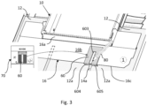
Fig. 3 the cuttingguide 60 may be used as follows:
In addition to the method outlined above in the opening part of the present description with reference toFig. 2 , in step e) "making for each cut standing seam, a cut-out 20 at alower edge 22 of thebottom flashing member 16", each cut-out 20 is provided as follows involves:
Thebottom flashing element 16 is positioned loosely against thelower side 10a of theroof element 10 and on top of the standingseams 14a, - a cutting
guide 60, e.g. as shown inFigs. 5 to 8 is provided, - the
base 601 of the cuttingguide 60 is positioned against thesecond leg 16b of thebottom flashing element 16 the twoangle portions seams 14a and abutting alower edge 16c of thesecond leg 16b of thebottom flashing element 16, - marking and/or cutting the
second leg 16b of thebottom flashing element 16 following the outline of thetrack 603. - The marking may be made initially, e.g. by means of a pen or a
pencil 80 as indicated inFig. 3 for thesecond leg 16b to be cut subsequently, or the marking may be dispensed with, and the cutting be made directly. - The cutting
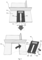
guide 60 may be made of any suited material, but, referring toFig. 4 , in a preferred embodiment the cutting guide may be provided by acardboard packaging 70, especially a corrugated cardboard packaging, e.g. for abottom flashing member 16, said cardboard packaging comprising a section ofcardboard material 701 having asurface 701a, wherein theoutlines base 601, atrack 603, and twoangle portions 604; 605 of a bottom flashingmember cutting guide 60 according to the present invention, are marked on saidsurface 701a. The outlining outlines 704, 705, 706, 707 may e.g. include visual markings and/or score lines. - The outlines comprise a
line 702 connecting distal ends of theangle portions 604; 605 distal from thebase 601. In the example shown theline 702 distal ends of theangle portions 604; 605 distal from thebase 601 and delimitations of the distal ends of theangle portions 604; 605 distal from the base 601 are provided by a free edge of the section ofcardboard material 701 and in this case further separation there along is not necessary. - Further the outlines comprise a
straight line 703 separating thebase 601 and theangle portions 604; 605. When the ofcardboard material 701 is a planar piece of material thestraight line 703 separating thebase 601 and theangle portions 604; 605 facilitates bending theangle portions 604; 605 at angles α relative to the base 601 in a correct manner to ensure that thetrack 603 will be positioned centrally relative to thestanding seam 14a when the cutting guide is positioned as shown inFig. 3 and explained above. - In an alternative embodiment, not shown of a cardboard packaging the section of cardboard material comprises two sides meeting at a corner of the packaging, a part of a first side of said two sides constituting the base of the bottom flashing member cutting guide, and a part of a second side of said two sides constituting the two angle portions, whereby an outline of the base and the two angle portions, including outlines of the track and the second side edge and third side edge of the bottom flashing member cutting guide is marked on said first side and said second side, respectively.
- When removing the cutting
guide 60 from the section ofcardboard material 701 a piece ofcardboard material 708 basically corresponding to thetrack 603 may be removed. At least a piece ofcardboard material 708a between the twoangle portions 604; 605 should be removed in order to allow the latter to straddle thestanding seam 14a. - If the angle β is similar to the mutual angle of the sides of the
standing seam 14a and the distance d between the second and thethird side edge standing seam 14a when the angle α is 90° the cuttingguide 60 including thetrack 603 will be positioned centrally relative to thestanding seam 14a to provide for a correctly positioned cut-out 20 for accommodating thelower part 30 of the cover device during installation of the flashing. - Due to the fact that the width w of the track is bigger than the distance d between the second and the
third side edge lower part 30 of the cover device. - If the angle β not quite similar to the mutual angle of the sides of the
standing seam 14a and the distance d between the second and thethird side edge standing seam 14a then the angle α should me adjusted to get the cuttingguide 60 correctly and centrally positioned relative to thestanding seam 14a. - It is possible to use the cutting
guide 60 with the piece ofcardboard material 708 removed thetrack 603 left open. Thereby, as mentioned above a pen orpencil 80 may be used to mark for the cut-out 20. - Alternatively, it is possible the track is merely marked, and in such case, it is possible to insert e.g. a pointed knife through the material of the cutting guide and e.g. mark the bottom flashing element by cutting the surface thereof while cutting through the material of the cutting guide following the marked track. Subsequently the bottom flashing element may be cut using e.g. a pair of shears to finalize the cut-
out 20.
Claims (14)
- A bottom flashing member cutting guide (60) for guiding cutting of a bottom flashing member for a roof penetrating element, said bottom flashing member cutting guide (60) comprisinga base (601) having a first side edge (602) and a track (603) extending from the first side edge (602) into the base (601); andtwo angle portions (604; 605) depending from the base (601) and limiting an opening (606) adjoining said track (603) in the base (601),wherein said track (603) has a width (w) in a direction (x) along the first side edge (602), the two angle portions (604; 605) respectively have a second side edge (607) and a third side edge (608), the second side edge (607) and the third side edge (608) defining the opening (606), the third side edge (608) being vis-à-vis the second side edge (607),a mutual distance (d) between the second side edge (607) and the third side edge (608) being smaller than the width (w) of the track (603).
- A bottom flashing member cutting guide (60) according to claim 1, wherein the two angle portions (604; 605) depending from the base (601) are connected to the base by connections (604a; 605a) to extend at angles (α) relative to the base (601), said connections (604a; 605a) being flexible whereby said angles (α) are adjustable.
- A bottom flashing member cutting guide (60) according to claim 1, wherein the two angle portions (604; 605) depending from the base (601) are connected to the base by connections (604a; 605a) to extend at angles relative to the base, said connections (604a; 605a) being rigid to keep said angles (α) constant, preferably at right angles.
- A bottom flashing member cutting guide (60) according to any one of claims 1 to 3, wherein the track (603) is defined by at least one recessed portion recessed in the base (601).
- A bottom flashing member cutting guide (60) according to any one of claims 1 to 4, wherein the second side edge (607) and third side edge (608) define straight lines (607a; 608a) that extend mutually diverging away from the base to define an angle (β) between them.
- A bottom flashing member cutting guide (60) according to any one of claims 1 to 5, wherein the bottom flashing member cutting guide (60) comprises a flat material.
- A bottom flashing member cutting guide (60) according to claim 6, wherein the material is a paper-based material, preferably cardboard, more preferably corrugated cardboard.
- A cardboard packaging (70), especially a corrugated cardboard packaging, preferably for a bottom flashing member (16), said cardboard packaging comprising a section of cardboard material (701) having a surface (701a), wherein the outlines (704, 705, 706, 707) of a base (601), a track (603), and two angle portions (604; 605) of a bottom flashing member cutting guide (60) according to any one of the preceding claims, are marked on said surface (701a).
- A cardboard packaging according to claim 8, wherein the outlining outlines (704, 705, 706, 707) includes visual markings and/or score lines.
- A cardboard packaging according to claim 8 or 9, wherein the outlines comprise a line (702) connecting distal ends of the angle portions (604; 605) relative to/distal from the base (601).
- A cardboard packaging according to any one of claims 8 to 10, wherein the outlines comprise a straight line (703) separating the base (601) and the angle portions (604; 605).
- A cardboard packaging according to any one of claims 8 to 11, wherein said section of cardboard material comprises two sides meeting at a corner of the packaging, a part of a first side of said two sides constituting the base of the bottom flashing member cutting guide, and a part of a second side of said two sides constituting the two angle portions, whereby an outline of the base and the two angle portions, including outlines of the track and the second side edge and third side edge of the bottom flashing member cutting guide is marked on said first side and said second side, respectively.
- A method of flashing a roof element, the method comprising the steps of:a) mounting a full roofing panel (12) at a first side of the roof element (10);b) mounting lower roofing panels (12a) below the roof element (10), seams (14a) between the lower roofing panels (12a) extending down the roof from a position adjacent a lower side (10a) of the roof element (10);c) for each standing seam (14a) between lower roofing panels (12a), removing part of the standing seam (14a) between the lower roofing panels (12a) from an upper edge (12b) thereof proximal the roof element and a predetermined distance away from the roof element leaving a cut upper edge (18) of the respective standing seam (14a) and a gap (19) between adjacent cut edges of the lower roofing panels (12a);d) mounting the lower part (30) of the device to cover said upper edge (18) and the adjacent part of the standing seam (14a);e) making for each cut standing seam, a cut-out (20) at a lower edge (22) of the bottom flashing member (16) to accommodate a raised wall (35) of the lower part (30) of the device;f) mounting the bottom flashing member (16); andg) for each cut standing edge (14a), mounting the upper part (50) of the device whereby a cover portion (51) of the upper part (50) is placed over an elongated recess (32) of the lower part (30); whereinthe making of the cut-out (20) involves:positioning the bottom flashing element (16) loosely against the lower side (10a) of the roof element (10) and on top of the standing seams (14a),providing a bottom flashing member cutting guide (60) according to any one of claims 1 to 7,positioning the base of the bottom flashing member cutting guide (60) against the second leg (16b) of the bottom flashing element (16) the two angle portions (604, 605) straddling an underlying one of the standing seams (14a) and abutting a lower edge (16c) of the second leg (16b) of the bottom flashing element (16),marking and/or cutting the second leg (16b) of the bottom flashing element (16) following the outline of the track (603).
- A method according to claim 13, wherein the bottom flashing member cutting guide (60) is a part of a cardboard packaging (70) according to any one of claims 8 to 10, and wherein the making of the cut-out (20) involves removing the bottom flashing member cutting guide (60) from the cardboard packaging (70), and at least removing a piece of cardboard material (708) between the second side edge (607) and the third side edge (608).
Applications Claiming Priority (2)
| Application Number | Priority Date | Filing Date | Title |
|---|---|---|---|
| DKPA202370170A DK202370170A1 (en) | 2023-04-05 | 2023-04-05 | A flashing assembly comprising a top flashing arrangement, a roof element system comprising such a flashing assembly, and a method of manufacturing a flashing assembly |
| DKPA202370443A DK181855B1 (en) | 2023-04-05 | 2023-08-28 | A bottom flashing member cutting guide, a cardboard packaging, and a method of flashing a roof element |
Publications (1)
| Publication Number | Publication Date |
|---|---|
| EP4442922A1 true EP4442922A1 (en) | 2024-10-09 |
Family
ID=90481815
Family Applications (1)
| Application Number | Title | Priority Date | Filing Date |
|---|---|---|---|
| EP24166262.6A Pending EP4442922A1 (en) | 2023-04-05 | 2024-03-26 | A bottom flashing member cutting guide, a cardboard packaging, and a method of flashing a roof element |
Country Status (1)
| Country | Link |
|---|---|
| EP (1) | EP4442922A1 (en) |
Citations (5)
| Publication number | Priority date | Publication date | Assignee | Title |
|---|---|---|---|---|
| US5027576A (en) * | 1989-02-15 | 1991-07-02 | Dobel Bygg Ab | Apparatus and method for providing a throughgoing duct in a raised seam joint metal roof |
| US5533667A (en) * | 1995-09-22 | 1996-07-09 | Perf-Pak | Separable modular containers |
| US6151838A (en) * | 1998-11-24 | 2000-11-28 | Golden Eagle Building Products Inc. | Roof curb and method of installation |
| EP4089025A2 (en) * | 2021-05-12 | 2022-11-16 | VKR Holding A/S | A packed roof window |
| EP4279684A1 (en) | 2022-05-19 | 2023-11-22 | VKR Holding A/S | A device for flashing a part of a standing seam, a kit of parts for flashing a roof element, and a method of flashing a roof element |
-
2024
- 2024-03-26 EP EP24166262.6A patent/EP4442922A1/en active Pending
Patent Citations (5)
| Publication number | Priority date | Publication date | Assignee | Title |
|---|---|---|---|---|
| US5027576A (en) * | 1989-02-15 | 1991-07-02 | Dobel Bygg Ab | Apparatus and method for providing a throughgoing duct in a raised seam joint metal roof |
| US5533667A (en) * | 1995-09-22 | 1996-07-09 | Perf-Pak | Separable modular containers |
| US6151838A (en) * | 1998-11-24 | 2000-11-28 | Golden Eagle Building Products Inc. | Roof curb and method of installation |
| EP4089025A2 (en) * | 2021-05-12 | 2022-11-16 | VKR Holding A/S | A packed roof window |
| EP4279684A1 (en) | 2022-05-19 | 2023-11-22 | VKR Holding A/S | A device for flashing a part of a standing seam, a kit of parts for flashing a roof element, and a method of flashing a roof element |
Non-Patent Citations (2)
| Title |
|---|
| ANONYMOUS: "Flashing Guide - www.roofcladinfo.com", 21 June 2020 (2020-06-21), pages 1 - 8, XP093191942, Retrieved from the Internet <URL:https://web.archive.org/web/20200621130156/http://www.roofcladinfo.com/flashingguide> [retrieved on 20240801] * |
| ANONYMOUS: "Flashing Guide with figures - www.roofcladinfo.com", 21 June 2020 (2020-06-21), pages 1 - 8, XP093191947, Retrieved from the Internet <URL:https://www.roofcladinfo.com/flashingguide> [retrieved on 20240801] * |
Similar Documents
| Publication | Publication Date | Title |
|---|---|---|
| CN100427705C (en) | Waterproof component with adaptable corners | |
| US6912799B1 (en) | Marking and scoring guide | |
| EP2027977A1 (en) | Punch | |
| US8726592B2 (en) | Drywall corner or a transition corner | |
| US20150154894A1 (en) | Profiles used in generating channel letters | |
| US7788857B2 (en) | Closure rail for roofing and method using same | |
| EP2711480A2 (en) | A tool for use in mounting a vapour barrier collar and a method for mounting a vapour barrier collar | |
| US5295644A (en) | Bracket for mounting an electrical outlet box | |
| DK202370443A1 (en) | A bottom flashing member cutting guide, a cardboard packaging, and a method of flashing a roof element | |
| EP3575510A1 (en) | A wind-proofing pad, a kit including a plurality of wind-proofing pads and a sealing collar for use when installing a window frame, and method for installing a window frame in an inclined roof structure | |
| US20150224555A1 (en) | Device and method for generating channel letters | |
| HK1060484A2 (en) | A die-cutting razor for die-cutting folding ruled lines on sheets | |
| US6073400A (en) | Roof drip edge construction, corner assemblies therefor and methods of making same | |
| EP3575509B1 (en) | A method for providing an installation aid, an installation aid adapted for use when mounting a window frame in a roof structure of a building, and a kit including an installation aid | |
| CN219256600U (en) | Cardboard fluting device | |
| US20070254794A1 (en) | Envelope-Making Aid | |
| EP2701863B1 (en) | Generating channel letters using profiles | |
| EP1013847B1 (en) | Insulating panel for floor heating systems | |
| WO2012121001A1 (en) | Index forming tool | |
| JPS6356078B2 (en) | ||
| JP6756604B2 (en) | Packaging box | |
| JP4424625B1 (en) | Paper cutting aid | |
| JPH0421946Y2 (en) | ||
| WO2009013487A2 (en) | Apparatus for making boxes | |
| KR20230152543A (en) | Tringle set |
Legal Events
| Date | Code | Title | Description |
|---|---|---|---|
| PUAI | Public reference made under article 153(3) epc to a published international application that has entered the european phase |
Free format text: ORIGINAL CODE: 0009012 |
|
| STAA | Information on the status of an ep patent application or granted ep patent |
Free format text: STATUS: THE APPLICATION HAS BEEN PUBLISHED |
|
| AK | Designated contracting states |
Kind code of ref document: A1 Designated state(s): AL AT BE BG CH CY CZ DE DK EE ES FI FR GB GR HR HU IE IS IT LI LT LU LV MC ME MK MT NL NO PL PT RO RS SE SI SK SM TR |
|
| STAA | Information on the status of an ep patent application or granted ep patent |
Free format text: STATUS: REQUEST FOR EXAMINATION WAS MADE |
|
| 17P | Request for examination filed |
Effective date: 20250407 |